EP3827727B1 - Mopping member, mopping apparatus, cleaning robot, and control method for cleaning robot - Google Patents
Mopping member, mopping apparatus, cleaning robot, and control method for cleaning robot Download PDFInfo
- Publication number
- EP3827727B1 EP3827727B1 EP19854156.7A EP19854156A EP3827727B1 EP 3827727 B1 EP3827727 B1 EP 3827727B1 EP 19854156 A EP19854156 A EP 19854156A EP 3827727 B1 EP3827727 B1 EP 3827727B1
- Authority
- EP
- European Patent Office
- Prior art keywords
- mop
- turntable
- rotating center
- diameter edge
- short
- Prior art date
- Legal status (The legal status is an assumption and is not a legal conclusion. Google has not performed a legal analysis and makes no representation as to the accuracy of the status listed.)
- Active
Links
Images




Classifications
-
- A—HUMAN NECESSITIES
- A47—FURNITURE; DOMESTIC ARTICLES OR APPLIANCES; COFFEE MILLS; SPICE MILLS; SUCTION CLEANERS IN GENERAL
- A47L—DOMESTIC WASHING OR CLEANING; SUCTION CLEANERS IN GENERAL
- A47L11/00—Machines for cleaning floors, carpets, furniture, walls, or wall coverings
- A47L11/40—Parts or details of machines not provided for in groups A47L11/02 - A47L11/38, or not restricted to one of these groups, e.g. handles, arrangements of switches, skirts, buffers, levers
-
- A—HUMAN NECESSITIES
- A47—FURNITURE; DOMESTIC ARTICLES OR APPLIANCES; COFFEE MILLS; SPICE MILLS; SUCTION CLEANERS IN GENERAL
- A47L—DOMESTIC WASHING OR CLEANING; SUCTION CLEANERS IN GENERAL
- A47L11/00—Machines for cleaning floors, carpets, furniture, walls, or wall coverings
- A47L11/28—Floor-scrubbing machines, motor-driven
- A47L11/282—Floor-scrubbing machines, motor-driven having rotary tools
-
- A—HUMAN NECESSITIES
- A47—FURNITURE; DOMESTIC ARTICLES OR APPLIANCES; COFFEE MILLS; SPICE MILLS; SUCTION CLEANERS IN GENERAL
- A47L—DOMESTIC WASHING OR CLEANING; SUCTION CLEANERS IN GENERAL
- A47L11/00—Machines for cleaning floors, carpets, furniture, walls, or wall coverings
- A47L11/24—Floor-sweeping machines, motor-driven
-
- A—HUMAN NECESSITIES
- A47—FURNITURE; DOMESTIC ARTICLES OR APPLIANCES; COFFEE MILLS; SPICE MILLS; SUCTION CLEANERS IN GENERAL
- A47L—DOMESTIC WASHING OR CLEANING; SUCTION CLEANERS IN GENERAL
- A47L11/00—Machines for cleaning floors, carpets, furniture, walls, or wall coverings
- A47L11/28—Floor-scrubbing machines, motor-driven
- A47L11/282—Floor-scrubbing machines, motor-driven having rotary tools
- A47L11/283—Floor-scrubbing machines, motor-driven having rotary tools the tools being disc brushes
-
- A—HUMAN NECESSITIES
- A47—FURNITURE; DOMESTIC ARTICLES OR APPLIANCES; COFFEE MILLS; SPICE MILLS; SUCTION CLEANERS IN GENERAL
- A47L—DOMESTIC WASHING OR CLEANING; SUCTION CLEANERS IN GENERAL
- A47L11/00—Machines for cleaning floors, carpets, furniture, walls, or wall coverings
- A47L11/40—Parts or details of machines not provided for in groups A47L11/02 - A47L11/38, or not restricted to one of these groups, e.g. handles, arrangements of switches, skirts, buffers, levers
- A47L11/4011—Regulation of the cleaning machine by electric means; Control systems and remote control systems therefor
-
- A—HUMAN NECESSITIES
- A47—FURNITURE; DOMESTIC ARTICLES OR APPLIANCES; COFFEE MILLS; SPICE MILLS; SUCTION CLEANERS IN GENERAL
- A47L—DOMESTIC WASHING OR CLEANING; SUCTION CLEANERS IN GENERAL
- A47L11/00—Machines for cleaning floors, carpets, furniture, walls, or wall coverings
- A47L11/40—Parts or details of machines not provided for in groups A47L11/02 - A47L11/38, or not restricted to one of these groups, e.g. handles, arrangements of switches, skirts, buffers, levers
- A47L11/4036—Parts or details of the surface treating tools
- A47L11/4038—Disk shaped surface treating tools
-
- A—HUMAN NECESSITIES
- A47—FURNITURE; DOMESTIC ARTICLES OR APPLIANCES; COFFEE MILLS; SPICE MILLS; SUCTION CLEANERS IN GENERAL
- A47L—DOMESTIC WASHING OR CLEANING; SUCTION CLEANERS IN GENERAL
- A47L11/00—Machines for cleaning floors, carpets, furniture, walls, or wall coverings
- A47L11/40—Parts or details of machines not provided for in groups A47L11/02 - A47L11/38, or not restricted to one of these groups, e.g. handles, arrangements of switches, skirts, buffers, levers
- A47L11/4063—Driving means; Transmission means therefor
- A47L11/4069—Driving or transmission means for the cleaning tools
-
- A—HUMAN NECESSITIES
- A47—FURNITURE; DOMESTIC ARTICLES OR APPLIANCES; COFFEE MILLS; SPICE MILLS; SUCTION CLEANERS IN GENERAL
- A47L—DOMESTIC WASHING OR CLEANING; SUCTION CLEANERS IN GENERAL
- A47L2201/00—Robotic cleaning machines, i.e. with automatic control of the travelling movement or the cleaning operation
-
- A—HUMAN NECESSITIES
- A47—FURNITURE; DOMESTIC ARTICLES OR APPLIANCES; COFFEE MILLS; SPICE MILLS; SUCTION CLEANERS IN GENERAL
- A47L—DOMESTIC WASHING OR CLEANING; SUCTION CLEANERS IN GENERAL
- A47L2201/00—Robotic cleaning machines, i.e. with automatic control of the travelling movement or the cleaning operation
- A47L2201/06—Control of the cleaning action for autonomous devices; Automatic detection of the surface condition before, during or after cleaning
Definitions
- the present invention relates to the technical field of cleaning equipment, and more particularly relates to a mopping member, a mopping apparatus, a cleaning robot, and a control method for a cleaning robot.
- JPS363200731A discloses a floor cleaning device, including a vehicle body, the vehicle body includes active wheels provided in front of a direction of travel and drive wheels provided in a rear of the direction of travel; a back of the vehicle body is provided to be in contact with the ground.
- a plurality of cleaning brushes are configured for rotating to make the sewage to enter the vehicle body.
- a cleaning brush attachment of the vehicle body is provided with a water holding device for holding water.
- a suction device for sucking out the sewage sucked by the cleaning brush.
- the present disclosure provides a cleaning robot, including a mopping drive mechanism and a mopping apparatus;
- the present invention provides a control method for a cleaning robot, applied to the above cleaning robot, the control method including: driving, by the mopping drive mechanism, the first turntable and the first mop to rotate with respect to the chassis of the cleaning robot around the rotation axis of the first turntable, and driving the second turntable and the second mop to rotate with respect to the chassis of the cleaning robot around the rotation axis of the second turntable; where when the mopping drive mechanism drives the first turntable and the second turntable to rotate, the first turntable and the second turntable are controlled to rotate in opposite rotating directions and at a same rotating speed; and during rotation, the gap between the first mop and the second mop is always formed between the long-diameter edge and the short-diameter edge; before the operation of in a case that the mopping drive mechanism drives the first turntable and the second turntable to rotate, the control method further includes: installing the first mop at one of the plurality of first inserting positions, and installing the second mop at one of the plurality of second inserting
- the first mop includes a first long-diameter edge and a first short-diameter edge that are connected via a first endpoint.
- the distance from any point on the first long-diameter edge to the first rotating center is greater than half of the rotating center distance, and the distance from any point on the first short-diameter edge to the first rotating center is less than half of the rotating center distance; the distance from the first endpoint to the first rotating center is equal to half of the rotating center distance.
- the second mop includes a second long-diameter edge and a second short-diameter edge that are connected via a second endpoint.
- the distance from any point on the second long-diameter edge to the second rotating center is greater than half of the rotating center distance, and the distance from any point on the second short-diameter edge to the second rotating center is less than half of the rotating center distance; the distance from the second endpoint to the second rotating center is equal to half of the rotating center distance.
- the short-diameter edge of one mop corresponds to the long-diameter edge of the other mop.
- the gap between the first mop and the second mop is formed between the short-diameter edge of one mop and the long-diameter edge of the other mop.
- the gap changes left and right as the first mop and the second mop are rotated. Even if there are processing errors in the first mop and the second mop, the first mop and the second mop when operation can cover the gap in between.
- the mops provided in the present invention by rotating, can cover the uncleaned area existed in case of using the traditional two circular mops, thereby improving the cleaning efficiency of the cleaning equipment.
- the mopping member provided in the first embodiment of the present invention used for a cleaning robot to mop and clean a floor surface, includes a first mop 1a and a second mop 2a.
- the first mop 1a is provided with a first rotating center O1
- the second mop 2a is provide with a second rotating center 02.
- a distance between the first rotating center O1 and the second rotating center O2 is a rotating center distance.
- the rotating center distance is a length of a connection line L between the first rotating center O1 and the second rotating center 02.
- the connection line between the first rotating center O1 and the second rotating center O2 is referred to as a rotating center connection line L for short.
- the first mop 1a and the second mop 1b are substantially triangular-like.
- the first mop 1a includes first long-diameter edges 101a and first short-diameter edges 102a that are connected via first endpoints 103a.
- the distance from any point on the first long-diameter edge 101a to the first rotating center O1 is greater than half of the rotating center distance, and the distance from any point on the first short-diameter edge 102a to the first rotating center O1 is less than half of the rotating center distance.
- the distance from the first endpoint 103a to the first rotating center O1 is equal to half of the rotating center distance.
- the second mop 2a includes second long-diameter edges 201a and second short-diameter edges 202a that are connected via second endpoints 203a.
- the distance from any point on the second long-diameter edge 201a to the second rotating center O2 is greater than half of the rotating center distance, and the distance from any point on the second short-diameter edge 202a to the second rotating center O2 is less than half of the rotating center distance.
- the distance from the second endpoint 203a to the second rotating center O2 is equal to half of the rotating center distance.
- the gap between the first mop 1a and the second mop 2a is formed between the first long-diameter edge 101a and the second short-diameter edge 202a, or formed between the second long-diameter edge 201a and the first short-diameter edge 102a.
- FIGS. 2 to 4 are schematic diagrams illustrating gaps of three different angles in case where the width of the gap between the first mop 1a and the second mop 2a is greater than 0.
- the gap between the first mop 1a and the second mop 2a being greater than 0 is typically caused by processing errors. It can be seen from FIGS. 2 to 4 that at a certain moment there exists an uncleaned area caused by the gaps of three different angles.
- the uncleaned area is an area that has not been cleaned by the mops, generally caused by the gap.
- FIGS. 2 , 3 , and 4 illustrate a state that the rotating center connection line L passes through the point on the first short-diameter edge 102a closest to the first rotating center O1 and the point on the second long-diameter edge 201a farthest from the second rotating center O2.
- FIG. 3 illustrates a state that the rotating center connection line L passes through the first endpoint and the second endpoint.
- FIG. 4 illustrates a state that the rotating center connection line L pass through the point on the second short-diameter edge 202a closest to the second rotating center O2 and the point on the first long-diameter edge 101a farthest from the first rotating center O1.
- the gaps between the first mop 1a and the second mop 2a are denoted by X1, X2, and X3, respectively.
- a side contour of the first mop 1a and a side contour of the second mop 2a are of the same shape.
- the first mop 1a includes a plurality of (here, three) same first long-diameter edges 101a and a plurality of (here, three) same first short-diameter edges 102a.
- the plurality of first long-diameter edges 101a and the plurality of first short-diameter edges 102a are alternately connected.
- the distance from a point on the first long-diameter edge 101a to the first rotating center O1 gradually increases as the point moves from either of two endpoints to the midpoint, and the distance from a point on the first short-diameter edge 102a to the first rotating center O1 gradually decreases as the point moves from either of two endpoints to the midpoint.
- the endpoint here refers to an intersection point of the first long-diameter edge 101a and the first short-diameter edge 102a, namely the first endpoint described above.
- the second mop 2a includes same plurality of (here, three) second long-diameter edges 201a and same plurality of (here, three) second short-diameter edges 202a.
- the plurality of second long-diameter edges 201a and the plurality of second short-diameter edges 202a are alternately connected.
- the distance from a point on the second long-diameter edge 201a to the second rotating center O2 gradually increases as the point moves from either of two endpoints to the midpoint, and the distance from a point on the second short-diameter edge 202a to the second rotating center O2 gradually decreases as the point moves from either of two endpoints to the midpoint.
- the endpoint here refers to an intersection point of the second long-diameter edge 201a and the second short-diameter edge 202a, namely the second endpoint described above.
- the plurality of second long-diameter edges 201a and the plurality of second short-diameter edges 202a are alternately connected, the two ends of each of the second long-diameter edges 201a are respectively the second endpoints, and the two ends of each of the second short-diameter edges 202a are respectively the second endpoints.
- the point farthest from the first rotating center O1 on the first long-diameter edge 101a is the midpoint of the first long-diameter edge 101a;
- the point farthest from the second rotating center O2 on the second long-diameter edge 201a is the midpoint of the second long-diameter edges 201a;
- the point closest to the first rotating center O1 on the first short-diameter edge 102a is the midpoint of the first short-diameter edge 102a;
- the point closest to the second rotating center O2 on the second short-diameter edge 202a is the midpoint of the second short-diameter edge 202a.
- FIG. 5 is a schematic diagram of a contour of the gaps between the first mop 1a and the second mop 2a when the two are rotated, where LK in the figure indicates the contour of the gaps.
- the gap X1 in FIG. 2 can be covered by the first mop 1a and the second mop 2a in the states shown in FIGS. 3 and 4 .
- the gap X2 in FIG. 3 can be covered by the first mop 1a and the second mop 2a in the states shown in FIGS. 2 and 4 .
- the gap X3 in FIG. 4 can be covered by the first mop 1a and the second mop 2a in the states shown in FIGS. 2 and 3 .
- the cleaning robot can cover the uncleaned area between the two mops in a very short time, thereby improving the cleaning efficiency.
- FIG. 7 is a schematic diagram of the mopping member provided by the first embodiment, where the width of the gap between the first mop and the second mop is 0, and the first mop 1a and the second mop 2a interfere with each other by squeezing each other.
- the condition that the gap between the first mop 1a and the second mop 2a is 0 and there exists the interference is generally caused by the processing errors.
- the first mop 1a and the second mop 2a with relatively large sizes due to the processing errors can also cover the uncleaned area therebetween at one time.
- FIG. 7 is a schematic diagram of the mopping member provided by the first embodiment, where the width of the gap between the first mop and the second mop is 0, and the first mop 1a and the second mop 2a interfere with each other by squeezing each other.
- the condition that the gap between the first mop 1a and the second mop 2a is 0 and there exists the interference is generally caused by the processing errors.
- the cleaning robot when the cleaning robot performs the mop self-cleaning at a base station 3, the self-cleaning of the sides of the first mop 1a and the second mop 2a can be realized by the interference between the first mop 1a and the second mop 2a.
- the interference area is indicated by GS.
- the base station 3 is provided with cleaning ribs 301, which enhances the cleaning effect of the mops.
- a mechanism for scraping the long-diameter edges and the short-diameter edges of the mops, so as to clean the sides of the mops.
- the mechanism needs to have a certain deformability and a certain scratch resistance, which results in excessive cost or short life of the mechanism.
- the rotation speed of the first mop 1a is the same as the rotation speed of the second mop 2a, the distance from a contact point of the two mops to the first rotating center is different from the distance from the contact point to the second rotating center.
- the long-diameter edge of one mop is in contact with the short-diameter edge of the other mop.
- different linear speeds are generated when the two mops are in contact with each other, thereby producing a speed difference. This helps to improve the cleaning effect. Accordingly, it is a reasonable cleaning approach to use the interference due to the squeezing between the first mop 1a and the second mop 2a for the self-cleaning of the sides.
- the width of the gap between the first mop 1a and the second mop 2a is 0, the first mop 1a and the second mop 2a just touch each other.
- a bottom surface of the first mop 1a is flush with a bottom surface of the second mop 2a.
- the bottom surface of the first mop 1a being flush with the bottom surface of the second mop 2a means that the bottom surface of the first mop 1a is permanently flush with the bottom surface of the second mop 2a. That is, in any working state, the bottom surface of the first mop 1a is always flush with the bottom surface of the second mop 2a.
- the bottom surface of the first mop 1a being flush with the bottom surface of the second mop 2a means that the bottom surface of the first mop 1a is temporally flush with the bottom surface of the second mop 2a. That is, in some working states, e.g., when there occurs no relative deflection between the bottom surface of the first mop 1a and the bottom surface of the second mop 2a, the bottom surface of the first mop 1a is flush with the bottom surface of the second mop 2a; while when there occurs a relative deflection between the bottom surface of the first mop 1a and the bottom surface of the second mop 2a, the bottom surface of the first mop 1a may not be flush with the bottom surface of the second mop 2a.
- the first long-diameter edge 101a is an arc-shaped edge convex about the first rotating center O1
- the first short-diameter edge 102a is a straight edge
- the second long-diameter edge 201a is an arc-shaped edge convex about the second rotating center O2
- the second short-diameter edge 202a is a straight edge.
- the first short-diameter edge 102a may be an arc-shaped edge convex about the first rotating center O1.
- the second short-diameter edge 202a may be an arc-shaped edge convex about the second rotating center O2.
- the side contours of the first mop and the second mop may have other specific shapes.
- the present invention does not limit the side contours of the first mop and the second mop.
- the side contours of the first mop and the second mop may have the shape shown in the second embodiment or the third embodiment.
- the mopping member provided in the second embodiment of the present invention includes a first mop 1b and a second mop 2b.
- the first mop 1b is provided with a first rotating center O1
- the second mop 2b is provide with a second rotating center O2.
- a distance between the first rotating center O1 and the second rotating center O2 is a rotating center distance.
- the rotating center distance is a length of a connection line L between the first rotating center O1 and the second rotating center O2.
- the connection line between the first rotating center O1 and the second rotating center O2 is referred to as a rotating center connection line L for short.
- the first mop 1b and the second mop 2b are substantially quadrilateral-like.
- the first mop 1b includes first long-diameter edges 101b and first short-diameter edges 102b that are connected via first endpoints.
- the distance from any point on the first long-diameter edge 101b to the first rotating center O1 is greater than half of the rotating center distance, and the distance from any point on the first short-diameter edge 102b to the first rotating center O1 is less than half of the rotating center distance.
- the distance from the first endpoint to the first rotating center O1 is equal to half of the rotating center distance.
- the second mop 2b includes second long-diameter edges 201b and second short-diameter edges 202b that are connected via second endpoints.
- the distance from any point on the second long-diameter edge 201b to the second rotating center O2 is greater than half of the rotating center distance, and the distance from any point on the second short-diameter edge 202b to the second rotating center O2 is less than half of the rotating center distance.
- the distance from the second endpoint to the second rotating center O2 is equal to half of the rotating center distance.
- the gap between the first mop 1a and the second mop 2b is formed between the first long-diameter edge 101b and the second short-diameter edge 202b, or formed between the second long-diameter edge 201b and the first short-diameter edge 102b.
- a side contour of the first mop 1b and a side contour of the second mop 2b are of the same shape.
- the first mop 1b includes a plurality of (here, four) same first long-diameter edges 101b and a plurality of (here, four) same first short-diameter edges 102b.
- the plurality of first long-diameter edges 101b and the plurality of first short-diameter edges 102b are alternately connected.
- the distance from a point on the first long-diameter edge 101b to the first rotating center O1 gradually increases as the point moves from either of two endpoints to the midpoint, and the distance from a point on the first short-diameter edge 102b to the first rotating center O1 gradually decreases as the point moves from either of two endpoints to the midpoint.
- the second mop 2b includes a plurality of (here, four) same second long-diameter edges 201b and a plurality of (here, four) same second short-diameter edges 202b.
- the plurality of second long-diameter edges 201b and the plurality of second short-diameter edges 202b are alternately connected.
- the distance from a point on the second long-diameter edge 201b to the first rotating center O1 gradually increases as the point moves from either of two endpoints to the midpoint, and the distance from a point on the second short-diameter edge 202b to the first rotating center O1 gradually decreases as the point moves from either of two endpoints to the midpoint.
- the mopping member in the second embodiment has the same function as that of the mopping member in the first embodiment.
- the specific implementation of the mopping member in the second embodiment may refer to the relevant description in the first embodiment. Further, the undescribed parts of the mopping member in the second embodiment may also refer to the detailed description of the mopping member in the first embodiment.
- the mopping member provided in the second embodiment of the present invention includes a first mop 1c and a second mop 2c.
- the first mop 1c is provided with a first rotating center O1
- the second mop 2c is provide with a second rotating center O2.
- a distance between the first rotating center O1 and the second rotating center O2 is a rotating center distance.
- the rotating center distance is a length of a connection line L between the first rotating center O1 and the second rotating center O2.
- the connection line between the first rotating center O1 and the second rotating center O2 is referred to as a rotating center connection line L for short.
- the first mop 1c and the second mop 1c are substantially oval-like.
- the first mop 1c includes first long-diameter edges 101c and first short-diameter edges 102c that are connected via first endpoints.
- the distance from any point on the first long-diameter edge 101c to the first rotating center O1 is greater than half of the rotating center distance, and the distance from any point on the first short-diameter edge 102c to the first rotating center O1 is less than half of the rotating center distance.
- the distance from the first endpoint to the first rotating center O1 is equal to half of the rotating center distance.
- the second mop 1c includes second long-diameter edges 201c and second short-diameter edges 202c that are connected via second endpoints.
- the distance from any point on the second long-diameter edge 201c to the second rotating center O2 is greater than half of the rotating center distance, and the distance from any point on the second short-diameter edge 202d to the second rotating center O2 is less than half of the rotating center distance.
- the distance from the second endpoint to the second rotating center O2 is equal to half of the rotating center distance.
- the gap between the first mop 1c and the second mop 2c is formed between the first long-diameter edge 101c and the second short-diameter edge 202c, or formed between the second long-diameter edge 201c and the first short-diameter edge 102c.
- the side contour of the first mop 1c and the side contour of the second mop 2c are of the same shape.
- the first mop 1c includes same plurality of (here, two) first long-diameter edges 101c and same plurality of (here, two) first short-diameter edges 102c.
- the plurality of first long-diameter edges 101c and the plurality of first short-diameter edges 102c are alternately connected.
- the distance from a point on the first long-diameter edge 101c to the first rotating center O1 gradually increases as the point moves from either of two endpoints to the midpoint, and the distance from a point on the first short-diameter edge 102c to the first rotating center O1 gradually decreases as the point moves from either of two endpoints to the midpoint.
- the endpoint herein refers to the intersection point of the first long-diameter edge 101c and the first short-diameter edge 102c.
- the second mop 2c includes a plurality of (here, two) same second long-diameter edges 201c and a plurality of (here, two) same second short-diameter edges 202c.
- the plurality of second long-diameter edges 201c and the plurality of second short-diameter edges 202c are alternately connected.
- the distance from a point on the second long-diameter edge 201c to the first rotating center O1 gradually increases as the point moves from either of two endpoints to the midpoint, and the distance from a point on the second short-diameter edge 202c to the first rotating center O1 gradually decreases as the point moves from either of two endpoints to the midpoint.
- the endpoint herein refers to the intersection point of the second long-diameter edge 201c and the second short-diameter edge 202c.
- the mopping member in the third embodiment has the same function as that of the mopping member in the first embodiment.
- the specific implementation of the mopping member in the third embodiment may refer to the relevant description in the first embodiment. Further, the undescribed parts of the mopping member in the third embodiment may also refer to the detailed description of the mopping member in the first embodiment.
- the fourth embodiment of the present invention provides a mopping apparatus.
- the mopping apparatus includes a first turntable 5, a second turntable 6, and the mopping member according to any of the embodiments described above.
- a side edge of the first turntable 5 and a side edge of the second turntable 6 are arranged to be spaced apart, so that the first turntable 5 and the second turntable 6 are rotated relatively independently without touching each other.
- the first mop is fixedly connected to the bottom of the first turntable 5, and is configured to rotate with the first turntable 5.
- the second mop is fixedly connected to the bottom of the second turntable 6, and is configured to rotate with the second turntable 6.
- the rotation axis of the first turntable 5 is configured to pass through the first rotating center O1
- the rotation axis of the second turntable 6 is configured to pass through the second rotating center O2.
- the ways to connect the first mop and the first turntable 5 and the ways to connect the second mop and the second turntable 6 include, but are not limited to, a glued connection, a bolted connection, a detachable connection through a Velcro provided between the first mop and the first turntable 5, or a snap-fit connection through a button fastener, and so on.
- the side contour of the first turntable 5 and the side contour of the first mop are of the same shape, and the side contour of the first turntable 5 falls within the side contour of the first mop.
- the side contour of the second turntable 6 and the side contour of the second mop are of the same shape, and the side contour of the second turntable 6 falls within the side contour of the second mop.
- the distance between the side contour of the first turntable 5 and the side contour of the first mop is equal; along different rays radiating from the second rotating center O2, the distance between the side contour of the second turntable 6 and the side contour of the second mop is equal.
- the cleaning robot provided in the fifth embodiment of the present invention includes a mopping drive mechanism 4 and the mopping apparatus according to the fourth embodiment described above.
- the mopping drive mechanism 4 Driven by the mopping drive mechanism 4, the first turntable 5 and the first mop 1a can rotate with respect to a chassis of the cleaning robot around the rotation axis of the first turntable 5; the second turntable 6 and the second mop 2a can rotate with respect to the chassis of the cleaning robot around the rotation axis of the second turntable 6.
- the mopping drive mechanism 4 includes a first output shaft 401 and a second output shaft 402.
- a lower end of the first output shaft 401 is connected to a position where is the rotating center of the first turntable 5, and a lower end of the second output shaft 402 is connected to a position where is the rotating center of the second turntable 6.
- the axis of the first output shaft 401 is coincided with the rotation axis of the first turntable 5, and the axis of the second output shaft 402 is coincided with the rotation axis of the second turntable 6.
- the mopping drive mechanism 4 further includes a worm motor 403, a first worm gear drivingly connected to the first output shaft 401, and a second worm gear drivingly connected to the second output shaft 402.
- the worm motor 403 is configured to output torques.
- the first worm gear and the second worm gear are both engaged with the worm motor 403, to transmit the torques to the first output shaft 401 and the second output shaft 402.
- a specific working process is as follows: the torques output by the worm motor 403 are transmitted to the first worm gear and the second worm gear, so as to drive the first worm gear and the second worm gear to rotate; then, the first worm gear drives the first output shaft 401 to rotate, and the second worm gear drives the second output shaft 402 to rotate.
- the lower end of the first output shaft 401 is connected to the position where is the rotating center of the first turntable 5
- the lower end of the second output shaft 402 is connected to the position where is the rotating center of the second turntable 6.
- the first turntable 5 and the first mop can rotate with respect to the chassis of the cleaning robot around the rotation axis of the first turntable 5, the second turntable 6 and the second mop can rotate with respect to the chassis of the cleaning robot around the rotation axis of the second turntable 6.
- the first turntable 5 is provided with a first shaft sleeve 501 adapted for the first output shaft 401, so that the first output shaft 401 can be detachably inserted into the first shaft sleeve 501.
- the first shaft sleeve 501 being adapted for the first output shaft 401 means that the first output shaft 401 can be inserted into the first shaft sleeve 501.
- An outer peripheral surface of the first output shaft 401 and an inner wall surface of the first shaft sleeve 501 limit each other, so as to limit a relative rotation between the first output shaft 401 and the first shaft sleeve 501.
- a limit surface of the outer peripheral surface of the first output shaft 401 and a limit surface of the inner wall surface of the first shaft sleeve 501 limit each other, thereby limiting the relative rotation between the first output shaft 401 and the first shaft sleeve 501.
- a cross-section of the outer peripheral surface of the first output shaft 401 and a cross-section of the inner wall surface of the first shaft sleeve 501 are the same preset regular polygon.
- the outer peripheral surface of the first output shaft 401 is clamped with the inner wall surface of the first shaft sleeve 501; or in operation, the limit surface of the outer peripheral surface of the first output shaft 401 and the limit surface of the inner wall surface of the first shaft sleeve 501 are abutted each other, so as to limit the relative rotation between the first output shaft 401 and the first shaft sleeve 501.
- the second turntable 6 is provided with a second shaft sleeve 601 adapted for the second output shaft 402, so that the second output shaft 402 can be detachably inserted into the second shaft sleeve 601.
- the second shaft sleeve 601 being adapted for the second output shaft 402 means that the second output shaft 402 can be inserted into the second shaft sleeve 601.
- An outer peripheral surface of the second output shaft 402 and an inner wall surface of the second shaft sleeve 601 limit each other, so as to limit a relative rotation between the second output shaft 402 and the second shaft sleeve 601.
- a limit surface of the outer peripheral surface of the second output shaft 402 and a limit surface of the inner wall surface of the second shaft sleeve 601 limit each other, thereby limiting the relative rotation between the second output shaft 402 and the second shaft sleeve 601.
- a cross-section of the outer peripheral surface of the second output shaft 402 and a cross-section of the inner wall surface of the second shaft sleeve 601 are the same preset regular polygon.
- the outer peripheral surface of the second output shaft 402 is clamped with the inner wall surface of the second shaft sleeve 601; or in operation, the limit surface of the outer peripheral surface of the second output shaft 402 and the limit surface of the inner wall surface of the second shaft sleeve 601 are abutted each other, so as to limit the relative rotation between the second output shaft 402 and the second shaft sleeve 601.
- first output shaft 401 and the first shaft sleeve 501 There are a plurality of inserting positions for the first output shaft 401 and the first shaft sleeve 501, so that the first turntable 5 and the first mop have a plurality of installation positions with respect to the chassis of the cleaning robot.
- second output shaft 402 and the second shaft sleeve 601 There are a plurality of inserting positions for the second output shaft 402 and the second shaft sleeve 601, so that the second turntable 6 and the second mop have a plurality of installation positions with respect to the chassis of the cleaning robot.
- the first mop and the second mop can be installed at a target relative installation position (a correct relative angle).
- the first mop and the second mop can be at the target relative installation position.
- the gap between the first mop and the second mop is formed between the first long-diameter edge and the second short-diameter edge, or formed between the second long-diameter edge and the first short-diameter edge.
- the first mop and the second mop are rotational symmetry with a rotation angle of a preset angle.
- An absolute value of an angle difference between adjacent inserting positions of the plurality inserting positions for the first output shaft 401 and the first shaft sleeve 501 is N times the preset angle;
- an absolute value of an angle difference between adjacent inserting positions of the plurality inserting positions for the second output shaft 402 and the second shaft sleeve 601 is N times the preset angle; where N is a positive integer.
- the long-diameter edge of one mop corresponds to the short-diameter edge of the other mop on the rotating center connection line L during the rotations of the two mops
- users can insert the first output shaft 401 into the first shaft sleeve 501 at any optional inserting position, and insert the second output shaft 402 into the second shaft sleeve 601 at any optional inserting position.
- the first mop and the second mop are rotational symmetry with the rotation angle of 120 degrees.
- the first mop coincides with itself as it rotates through 120 degrees
- the second mop coincides with itself as it rotates through 120 degrees.
- there are three insertion potions for the second output shaft 402 and the second shaft sleeve 601 and the angle difference between adjacent inserting positions of the three inserting positions for the second output shaft 402 and the second shaft sleeve 601 is 120 degrees.
- the first mop and the second mop are rotational symmetry with the rotation angle of 60 degrees. That is, the first mop coincides with itself as it rotates through 60 degrees, and the second mop coincides with itself as it rotates through 60 degrees.
- there are six insertion potions for the first output shaft 401 and the first shaft sleeve 501 and the angle difference between adjacent inserting positions of the six inserting positions for the first output shaft 401 and the first shaft sleeve 501 is 60 degrees.
- there are three insertion potions for the second output shaft 402 and the second shaft sleeve 601, and the angle difference between adjacent inserting positions of the three inserting positions for the second output shaft 402 and the second shaft sleeve 601 is 120 degrees.
- there are two insertion potions for the second output shaft 402 and the second shaft sleeve 601, and the angle difference between the two inserting positions for the second output shaft 402 and the second shaft sleeve 601 is 180 degrees.
- first mop and the second mop are non-rotational symmetry.
- the absolute value of the angle difference between adjacent inserting positions of the plurality of inserting positions for the first output shaft 401 and the first shaft sleeve 501 is N times the preset angle
- the absolute value of the angle difference between adjacent inserting positions of the plurality of inserting positions for the second output shaft 402 and the second shaft sleeve 601 is N times the preset angle; where N is a positive Integer.
- the long-diameter edge of one mop corresponds to the short-diameter edge of the other mop on the rotating center connection line L during the rotations of the two mops
- users can insert the first output shaft 401 into the first shaft sleeve 501 at any optional inserting position, and insert the second output shaft 402 into the second shaft sleeve 601 at any optional inserting position.
- the first mop has one first long-diameter edge and one first short-diameter edge; the second mop has one second long-diameter edge and one second short-diameter edge.
- the first mop coincides with itself as it rotates through 360 degrees, and the second mop coincides with itself as it rotates through 360 degrees.
- the first output shaft 401 and the first shaft sleeve 501 can have only one inserting position
- the second output shaft 402 and the second shaft sleeve 601 can have only one inserting position.
- first output shaft 401 being detachably inserted into the first shaft sleeve 501 and the second output shaft 402 being detachably inserted into the second shaft sleeve 601 as an example.
- first output shaft 401 may be connected to the first turntable 5 in other ways, e.g., by welding or threading, and so on;
- second output shaft 402 may be connected to the second turntable 6 in other ways, e.g., by welding or threading, and so on.
- a control method for the cleaning robot includes: driving, by the mopping drive mechanism 4, the first turntable 5 and the first mop 1a to rotate around the rotation axis of the first turntable 5 with respect to the chassis of the cleaning robot, and driving the second turntable 6 and the second mop 2a to rotate around the rotation axis of the second turntable 6 with respect to the chassis of the cleaning robot.
- the first turntable 5 and the second turntable 6 are controlled to rotate in opposite rotating directions and at a same rotating speed.
- the gap between the first mop 1a and the second mop 2a is always formed between the long-diameter edge and the short-diameter edge.
- the method before the mopping drive mechanism 4 drives the first turntable 5 and the second turntable 6 to rotate, the method further includes: there being a plurality of first inserting positions for the first output shaft 401 and the first shaft sleeve 501, and there being a plurality of second inserting positions for the second output shaft 402 and the second shaft sleeve 601; installing the first mop 1a at one of the plurality of first inserting positions, and installing the second mop 2a at one of the plurality of second inserting positions; on the connection line between the first rotating center O1 and the second rotating center O2, the gap between the first mop 1a and the second mop 2a being formed between the first long-diameter edge 101a and the second short-diameter edge 202a, or the gap between the first mop 1a and the second mop 2a being formed between the second long-diameter edge 201a and the first short-diameter edge 102a.
- the mopping apparatus and the cleaning robot provided in the present invention, when the first mop and the second mop are rotated, the short-diameter edge of one mop corresponds to the long-diameter edge of the other mop.
- the gap between the first mop and the second mop is formed between the short-diameter edge of one mop and the corresponding long-diameter edge of the other mop.
- the gap moves left and right.
- the mops according to the embodiments by rotating, can cover the uncleaned gap area that existed in case of using the traditional two circular mops, thereby improving the cleaning efficiency of the cleaning equipment.
Landscapes
- Cleaning Implements For Floors, Carpets, Furniture, Walls, And The Like (AREA)
- Nozzles For Electric Vacuum Cleaners (AREA)
- Manipulator (AREA)
Description
- The present invention relates to the technical field of cleaning equipment, and more particularly relates to a mopping member, a mopping apparatus, a cleaning robot, and a control method for a cleaning robot.
- The statement herein is merely used to provide background information related to the present invention, and is not intended to constitute the related art.
- As the cleaning field has been developed, more various types of cleaning equipment are available. Many types of cleaning equipment adopt a circular double turntable structure for cleaning, namely, by rotating two mops for cleaning. However, due to processing errors, it is difficult to make the two mops tangent to each other without leaving a gap therebetween. If the mops are relatively small, there generally exists a gap therebetween; if the mops are relatively large, the mops typically squeeze and deform each other, resulting in a gap therebetween. The above-mentioned gap disables the existing cleaning equipment to remove all dust or dirt from an area to be clean at one time. Hence, many types of cleaning equipment must clean the area to be clean several times, so as to remove all the dust or dirt from the area to be clean.
-
JPS363200731A - It is an object of the present invention to provide a a cleaning robot having a mopping drive mechanism and a mopping apparatus, and a control method for the cleaning robot, aiming to solve the problem that the existing cleaning equipment cannot remove all dust or dirt from the area to be cleaned at one time.
- In still another aspect, the present disclosure provides a cleaning robot, including a mopping drive mechanism and a mopping apparatus;
- wherein the mopping apparatus includes a mopping member; the mopping member comprises a first mop and a second mop;
- the first mop is provided with a first rotating center, and the second mop is provided with a second rotating center; a distance between the first rotating center and the second rotating center is a rotating center distance;
- the first mop includes a first long-diameter edge and a first short-diameter edge; a distance from any point on the first long-diameter edge to the first rotating center is greater than half of the rotating center distance, and a distance from any point on the first short-diameter edge to the first rotating center is less than half of the rotating center distance;
- the second mop includes a second long-diameter edge and a second short-diameter edge; a distance from any point on the second long-diameter edge to the second rotating center is greater than half of the rotating center distance, and a distance from any point on the second short-diameter edge to the second rotating center is less than half of the rotating center distance;
- the first mop and the second mop are driven to rotate by the mopping drive mechanism; a gap between the first mop and the second mop is formed between the first long-diameter edge and the second short-diameter edge, or formed between the second long-diameter edge and the first short-diameter edge;
- the mopping apparatus further includes a first turntable and a second turntable;
- a side edge of the first turntable and a side edge of the second turntable are configured to be spaced apart;
- the first mop is fixedly connected to a bottom of the first turntable, and is configured to rotate with the first turntable;
- the second mop is fixedly connected to a bottom of the second turntable, and is configured to rotate with the second turntable; and
- driven by the mopping drive mechanism, the first turntable and the first mop are rotatable with respect to a chassis of the cleaning robot around the rotation axis of the first turntable, and the second turntable and the second mop are rotatable with respect to the chassis of the cleaning robot around the rotation axis of the second turntable;
- the mopping drive mechanism includes a first output shaft and a second output shaft;
- the first turntable is provided with a first shaft sleeve; the first output shaft is configured to insert in the first shaft sleeve and limit the first shaft sleeve, to limit a relative rotation of the first output shaft and the first shaft sleeve; and
- the second turntable is provided with a second shaft sleeve; the second output shaft is configured to insert in the second shaft sleeve and limit the second shaft sleeve, to limit a relative rotation of the second output shaft and the second shaft sleeve;
- a position of the first shaft sleeve is adjustable relative to the first output shaft, to allow a position of the first mop is adjustable relative to the chassis of the cleaning robot, and a position of the second shaft sleeve is adjustable relative to the second output shaft, to allow a position of the second mop is adjustable relative to the chassis of the cleaning robot, so that the gap between the first mop and the second mop is formed between the first long-diameter edge and the second short-diameter edge, or formed between the second long-diameter edge and the first short-diameter edge;
- the first mop after a rotation is configured to coincide in shape with itself before the rotation in a case that the first mop rotates through a preset angle;
- the second mop after a rotation is configured to coincide in shape with itself before the rotation in a case that the second mop rotates through a preset angle;
- there are a plurality of first inserting positions for the first output shaft and the first shaft sleeve, and a rotation angle between adjacent first inserting positions is N times the preset angle; and
- there are a plurality of second inserting positions for the second output shaft and the second shaft sleeve, and a rotation angle between adjacent second inserting positions is N times the preset angle;
- wherein N is a positive integer.
- In still another aspect, the present invention provides a control method for a cleaning robot, applied to the above cleaning robot, the control method including: driving, by the mopping drive mechanism, the first turntable and the first mop to rotate with respect to the chassis of the cleaning robot around the rotation axis of the first turntable, and driving the second turntable and the second mop to rotate with respect to the chassis of the cleaning robot around the rotation axis of the second turntable; where when the mopping drive mechanism drives the first turntable and the second turntable to rotate, the first turntable and the second turntable are controlled to rotate in opposite rotating directions and at a same rotating speed; and during rotation, the gap between the first mop and the second mop is always formed between the long-diameter edge and the short-diameter edge;
before the operation of in a case that the mopping drive mechanism drives the first turntable and the second turntable to rotate, the control method further includes:
installing the first mop at one of the plurality of first inserting positions, and installing the second mop at one of the plurality of second inserting positions, so that on the connection line between the first rotating center and the second rotating center, the gap between the first mop and the second mop is formed between the first long-diameter edge and the second short-diameter edge, or formed between the second long-diameter edge and the first short-diameter edge. - In accordance with the mopping member, the mopping apparatus, the cleaning robot, and the control method for the cleaning robot provided in the present invention, the first mop includes a first long-diameter edge and a first short-diameter edge that are connected via a first endpoint. The distance from any point on the first long-diameter edge to the first rotating center is greater than half of the rotating center distance, and the distance from any point on the first short-diameter edge to the first rotating center is less than half of the rotating center distance; the distance from the first endpoint to the first rotating center is equal to half of the rotating center distance. Besides, the second mop includes a second long-diameter edge and a second short-diameter edge that are connected via a second endpoint. The distance from any point on the second long-diameter edge to the second rotating center is greater than half of the rotating center distance, and the distance from any point on the second short-diameter edge to the second rotating center is less than half of the rotating center distance; the distance from the second endpoint to the second rotating center is equal to half of the rotating center distance. As such, when the first mop and the second mop are rotated, the short-diameter edge of one mop corresponds to the long-diameter edge of the other mop. On the connection line between the first rotating center and the second rotating center, the gap between the first mop and the second mop is formed between the short-diameter edge of one mop and the long-diameter edge of the other mop. The gap changes left and right as the first mop and the second mop are rotated. Even if there are processing errors in the first mop and the second mop, the first mop and the second mop when operation can cover the gap in between. Thus, the mops provided in the present invention, by rotating, can cover the uncleaned area existed in case of using the traditional two circular mops, thereby improving the cleaning efficiency of the cleaning equipment.
-
-
FIG. 1 is a schematic diagram of a mopping member provided in a first embodiment of the present invention (triangular-like). -
FIG. 2 is a schematic diagram illustrating a width of a gap between a first mop and a second mop of the mopping member provided in the first embodiment being greater than 0 (a connection line between a first rotating center and a second rotating center passes through a point on a first short-diameter edge closest to the first rotating center and a point on a second long-diameter edge farthest from the second rotating center). -
FIG. 3 is a schematic diagram illustrating a width of a gap between a first mop and a second mop of the mopping member provided in the first embodiment being greater than 0 (a connection line between a first rotating center and a second rotating center passes through a first endpoint and a second endpoint). -
FIG. 4 is a schematic diagram illustrating a width of a gap between a first mop and a second mop of the mopping member provided in the first embodiment being greater than 0 (a connection line between a first rotating center and a second rotating center passes through a point on a second short-diameter edge closest to the second rotating center and a point on a first long-diameter edge farthest from the first rotating center). -
FIG. 5 is a schematic diagram illustrating a contour of gaps between a first mop and a second mop of the mopping member provided in the first embodiment. -
FIG. 6 is a schematic diagram illustrating that a first mop is rotated to a first inserting position and a second mop is rotated to a second inserting position when the first mop and the second mop of the mopping member provided in the first embodiment are rotated. -
FIG. 7 is a schematic diagram illustrating a width of a gap between a first mop and a second mop of the mopping member provided in the first embodiment being 0, and an interference due to squeezing between the first mop and the second mop (a connection line between a first rotating center and a second rotating center passes through a point on a first short-diameter edge closest to the first rotating center and a point on a second long-diameter edge farthest from the second rotating center). -
FIG. 8 is a schematic diagram illustrating a working principle that the mopping member provided in the first embodiment performs self-cleaning at a base station. -
FIG. 9 is a schematic diagram of a mopping member provided in a second embodiment of the present invention (quadrilateral-like). -
FIG. 10 is a schematic diagram of a mopping member provided in a third embodiment of the present invention (oval-like). -
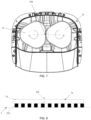
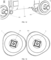
FIG. 11 is a schematic diagram of a mopping drive mechanism of a cleaning robot provided in a fifth embodiment of the present invention. -
FIG. 12 is a schematic diagram of a first output shaft and a second output shaft of the mopping drive mechanism of the cleaning robot provided in the fifth embodiment. -
FIG. 13 is a schematic diagram of a mopping apparatus of the cleaning robot provided in the fifth embodiment. - The realizing of the aim, functional characteristics and advantages of the present invention are further described in detail with reference to the accompanying drawings and the embodiments. It will be appreciated that the specific embodiments described herein are merely illustrative of the present invention and are not intended to limit the present invention.
- Please refer to
FIGS. 1 to 8 , the mopping member provided in the first embodiment of the present invention, used for a cleaning robot to mop and clean a floor surface, includes a first mop 1a and asecond mop 2a. The first mop 1a is provided with a first rotating center O1, and thesecond mop 2a is provide with a second rotating center 02. A distance between the first rotating center O1 and the second rotating center O2 is a rotating center distance. The rotating center distance is a length of a connection line L between the first rotating center O1 and the second rotating center 02. Hereinafter, the connection line between the first rotating center O1 and the second rotating center O2 is referred to as a rotating center connection line L for short. - In the first embodiment, the first mop 1a and the
second mop 1b are substantially triangular-like. - As shown in
FIG. 1 , the first mop 1a includes first long-diameter edges 101a and first short-diameter edges 102a that are connected viafirst endpoints 103a. The distance from any point on the first long-diameter edge 101a to the first rotating center O1 is greater than half of the rotating center distance, and the distance from any point on the first short-diameter edge 102a to the first rotating center O1 is less than half of the rotating center distance. The distance from thefirst endpoint 103a to the first rotating center O1 is equal to half of the rotating center distance. - The
second mop 2a includes second long-diameter edges 201a and second short-diameter edges 202a that are connected viasecond endpoints 203a. The distance from any point on the second long-diameter edge 201a to the second rotating center O2 is greater than half of the rotating center distance, and the distance from any point on the second short-diameter edge 202a to the second rotating center O2 is less than half of the rotating center distance. The distance from thesecond endpoint 203a to the second rotating center O2 is equal to half of the rotating center distance. - As shown in
FIGS. 2 to 4 , when the first mop 1a and thesecond mop 2a are rotated, on the rotating center connection line L, the gap between the first mop 1a and thesecond mop 2a is formed between the first long-diameter edge 101a and the second short-diameter edge 202a, or formed between the second long-diameter edge 201a and the first short-diameter edge 102a. -
FIGS. 2 to 4 are schematic diagrams illustrating gaps of three different angles in case where the width of the gap between the first mop 1a and thesecond mop 2a is greater than 0. The gap between the first mop 1a and thesecond mop 2a being greater than 0 is typically caused by processing errors. It can be seen fromFIGS. 2 to 4 that at a certain moment there exists an uncleaned area caused by the gaps of three different angles. The uncleaned area is an area that has not been cleaned by the mops, generally caused by the gap.FIG. 2 illustrates a state that the rotating center connection line L passes through the point on the first short-diameter edge 102a closest to the first rotating center O1 and the point on the second long-diameter edge 201a farthest from the second rotating center O2.FIG. 3 illustrates a state that the rotating center connection line L passes through the first endpoint and the second endpoint.FIG. 4 illustrates a state that the rotating center connection line L pass through the point on the second short-diameter edge 202a closest to the second rotating center O2 and the point on the first long-diameter edge 101a farthest from the first rotating center O1. In the three states shown inFIGS. 2 ,3 , and4 , the gaps between the first mop 1a and thesecond mop 2a are denoted by X1, X2, and X3, respectively. - As shown in
FIG. 1 , a side contour of the first mop 1a and a side contour of thesecond mop 2a are of the same shape. The first mop 1a includes a plurality of (here, three) same first long-diameter edges 101a and a plurality of (here, three) same first short-diameter edges 102a. The plurality of first long-diameter edges 101a and the plurality of first short-diameter edges 102a are alternately connected. The distance from a point on the first long-diameter edge 101a to the first rotating center O1 gradually increases as the point moves from either of two endpoints to the midpoint, and the distance from a point on the first short-diameter edge 102a to the first rotating center O1 gradually decreases as the point moves from either of two endpoints to the midpoint. The endpoint here refers to an intersection point of the first long-diameter edge 101a and the first short-diameter edge 102a, namely the first endpoint described above. In case where the plurality of first long-diameter edges 101a and the plurality of first short-diameter edges 102a are alternately connected, the two ends of each of the first long-diameter edges 101a are respectively the first endpoints, and the two ends of each of the first short-diameter edges 102a are respectively the first endpoints. - The
second mop 2a includes same plurality of (here, three) second long-diameter edges 201a and same plurality of (here, three) second short-diameter edges 202a. The plurality of second long-diameter edges 201a and the plurality of second short-diameter edges 202a are alternately connected. The distance from a point on the second long-diameter edge 201a to the second rotating center O2 gradually increases as the point moves from either of two endpoints to the midpoint, and the distance from a point on the second short-diameter edge 202a to the second rotating center O2 gradually decreases as the point moves from either of two endpoints to the midpoint. The endpoint here refers to an intersection point of the second long-diameter edge 201a and the second short-diameter edge 202a, namely the second endpoint described above. In case where the plurality of second long-diameter edges 201a and the plurality of second short-diameter edges 202a are alternately connected, the two ends of each of the second long-diameter edges 201a are respectively the second endpoints, and the two ends of each of the second short-diameter edges 202a are respectively the second endpoints. - In accordance with this, the point farthest from the first rotating center O1 on the first long-
diameter edge 101a is the midpoint of the first long-diameter edge 101a; the point farthest from the second rotating center O2 on the second long-diameter edge 201a is the midpoint of the second long-diameter edges 201a; the point closest to the first rotating center O1 on the first short-diameter edge 102a is the midpoint of the first short-diameter edge 102a; the point closest to the second rotating center O2 on the second short-diameter edge 202a is the midpoint of the second short-diameter edge 202a. -
FIG. 5 is a schematic diagram of a contour of the gaps between the first mop 1a and thesecond mop 2a when the two are rotated, where LK in the figure indicates the contour of the gaps. It can be seen that the gap X1 inFIG. 2 can be covered by the first mop 1a and thesecond mop 2a in the states shown inFIGS. 3 and4 . Similarly, the gap X2 inFIG. 3 can be covered by the first mop 1a and thesecond mop 2a in the states shown inFIGS. 2 and4 . Similarly, the gap X3 inFIG. 4 can be covered by the first mop 1a and thesecond mop 2a in the states shown inFIGS. 2 and3 . In operation, since rotation speeds of the first mop 1a and thesecond mop 2a are relatively high, usually several to dozens of revolutions per second, the cleaning robot can cover the uncleaned area between the two mops in a very short time, thereby improving the cleaning efficiency. - In addition, it can be seen from
FIG. 5 that during the rotations of the first mop 1a and thesecond mop 2a, the position of the gap formed between the first mop 1a and thesecond mop 2a is constantly changing. Thus, the gap appeared before will be covered in a very short time by the first long-diameter edge 101a of the first mop 1a or the second long-diameter edge 201a of thesecond mop 2a that rotates to the gap later. -
FIG. 7 is a schematic diagram of the mopping member provided by the first embodiment, where the width of the gap between the first mop and the second mop is 0, and the first mop 1a and thesecond mop 2a interfere with each other by squeezing each other. The condition that the gap between the first mop 1a and thesecond mop 2a is 0 and there exists the interference is generally caused by the processing errors. However, in operation, the first mop 1a and thesecond mop 2a with relatively large sizes due to the processing errors can also cover the uncleaned area therebetween at one time. In addition, as shown inFIG. 8 , with the first mop 1a and thesecond mop 2a having large processing sizes, when the cleaning robot performs the mop self-cleaning at abase station 3, the self-cleaning of the sides of the first mop 1a and thesecond mop 2a can be realized by the interference between the first mop 1a and thesecond mop 2a. InFIGS. 7 to 8 , the interference area is indicated by GS. As shown inFIG. 8 , thebase station 3 is provided with cleaningribs 301, which enhances the cleaning effect of the mops. - Generally, a mechanism is provided for scraping the long-diameter edges and the short-diameter edges of the mops, so as to clean the sides of the mops. However, since the rotation speeds of the mops are high, and a difference between the length of the long-diameter edge and the length of the short-diameter edge is large, the mechanism needs to have a certain deformability and a certain scratch resistance, which results in excessive cost or short life of the mechanism.
- In the embodiment of the present invention, the rotation speed of the first mop 1a is the same as the rotation speed of the
second mop 2a, the distance from a contact point of the two mops to the first rotating center is different from the distance from the contact point to the second rotating center. For example, the long-diameter edge of one mop is in contact with the short-diameter edge of the other mop. In this case, different linear speeds are generated when the two mops are in contact with each other, thereby producing a speed difference. This helps to improve the cleaning effect. Accordingly, it is a reasonable cleaning approach to use the interference due to the squeezing between the first mop 1a and thesecond mop 2a for the self-cleaning of the sides. - In this way, when the first mop and the second mop are self-cleaning at the base station, in case where the sizes of the first mop and the second mop are relatively large, there exists the interference area when they are rotated at the same speed. For example, the long-diameter edge of one mop and the short-diameter edge of the other mop interfere with each other due to the squeezing between the two mops. As such, different linear speeds are produced when they are in contact, which produces the speed difference, thereby realizing the self-cleaning of the sides of the mops.
- In some other specific implementations, if there is no design error in the first mop 1a and the
second mop 2a, the width of the gap between the first mop 1a and thesecond mop 2a is 0, the first mop 1a and thesecond mop 2a just touch each other. - In the first embodiment, a bottom surface of the first mop 1a is flush with a bottom surface of the
second mop 2a. - In some examples, the bottom surface of the first mop 1a being flush with the bottom surface of the
second mop 2a means that the bottom surface of the first mop 1a is permanently flush with the bottom surface of thesecond mop 2a. That is, in any working state, the bottom surface of the first mop 1a is always flush with the bottom surface of thesecond mop 2a. - In some other examples, the bottom surface of the first mop 1a being flush with the bottom surface of the
second mop 2a means that the bottom surface of the first mop 1a is temporally flush with the bottom surface of thesecond mop 2a. That is, in some working states, e.g., when there occurs no relative deflection between the bottom surface of the first mop 1a and the bottom surface of thesecond mop 2a, the bottom surface of the first mop 1a is flush with the bottom surface of thesecond mop 2a; while when there occurs a relative deflection between the bottom surface of the first mop 1a and the bottom surface of thesecond mop 2a, the bottom surface of the first mop 1a may not be flush with the bottom surface of thesecond mop 2a. - In the first embodiment, the first long-
diameter edge 101a is an arc-shaped edge convex about the first rotating center O1, and the first short-diameter edge 102a is a straight edge. The second long-diameter edge 201a is an arc-shaped edge convex about the second rotating center O2, and the second short-diameter edge 202a is a straight edge. - However, in some alternative embodiments of the first embodiment, the first short-
diameter edge 102a may be an arc-shaped edge convex about the first rotating center O1. Similarly, the second short-diameter edge 202a may be an arc-shaped edge convex about the second rotating center O2. - It will be appreciated that although the first embodiment is described by taking the first mop 1a and the
second mop 2a being substantially triangular-like as an example, the side contours of the first mop and the second mop may have other specific shapes. The present invention does not limit the side contours of the first mop and the second mop. For instance, the side contours of the first mop and the second mop may have the shape shown in the second embodiment or the third embodiment. - Please refer to
FIG. 9 , the mopping member provided in the second embodiment of the present invention includes afirst mop 1b and asecond mop 2b. Thefirst mop 1b is provided with a first rotating center O1, and thesecond mop 2b is provide with a second rotating center O2. A distance between the first rotating center O1 and the second rotating center O2 is a rotating center distance. The rotating center distance is a length of a connection line L between the first rotating center O1 and the second rotating center O2. Hereinafter, the connection line between the first rotating center O1 and the second rotating center O2 is referred to as a rotating center connection line L for short. - In the second embodiment, the
first mop 1b and thesecond mop 2b are substantially quadrilateral-like. - As shown in
FIG. 9 , thefirst mop 1b includes first long-diameter edges 101b and first short-diameter edges 102b that are connected via first endpoints. The distance from any point on the first long-diameter edge 101b to the first rotating center O1 is greater than half of the rotating center distance, and the distance from any point on the first short-diameter edge 102b to the first rotating center O1 is less than half of the rotating center distance. The distance from the first endpoint to the first rotating center O1 is equal to half of the rotating center distance. Thesecond mop 2b includes second long-diameter edges 201b and second short-diameter edges 202b that are connected via second endpoints. The distance from any point on the second long-diameter edge 201b to the second rotating center O2 is greater than half of the rotating center distance, and the distance from any point on the second short-diameter edge 202b to the second rotating center O2 is less than half of the rotating center distance. The distance from the second endpoint to the second rotating center O2 is equal to half of the rotating center distance. - When the
first mop 1b and thesecond mop 2b are rotated, on the rotating center connection line L, the gap between the first mop 1a and thesecond mop 2b is formed between the first long-diameter edge 101b and the second short-diameter edge 202b, or formed between the second long-diameter edge 201b and the first short-diameter edge 102b. - As shown in
FIG. 9 , a side contour of thefirst mop 1b and a side contour of thesecond mop 2b are of the same shape. Thefirst mop 1b includes a plurality of (here, four) same first long-diameter edges 101b and a plurality of (here, four) same first short-diameter edges 102b. The plurality of first long-diameter edges 101b and the plurality of first short-diameter edges 102b are alternately connected. The distance from a point on the first long-diameter edge 101b to the first rotating center O1 gradually increases as the point moves from either of two endpoints to the midpoint, and the distance from a point on the first short-diameter edge 102b to the first rotating center O1 gradually decreases as the point moves from either of two endpoints to the midpoint. - The
second mop 2b includes a plurality of (here, four) same second long-diameter edges 201b and a plurality of (here, four) same second short-diameter edges 202b. The plurality of second long-diameter edges 201b and the plurality of second short-diameter edges 202b are alternately connected. The distance from a point on the second long-diameter edge 201b to the first rotating center O1 gradually increases as the point moves from either of two endpoints to the midpoint, and the distance from a point on the second short-diameter edge 202b to the first rotating center O1 gradually decreases as the point moves from either of two endpoints to the midpoint. The mopping member in the second embodiment has the same function as that of the mopping member in the first embodiment. The specific implementation of the mopping member in the second embodiment may refer to the relevant description in the first embodiment. Further, the undescribed parts of the mopping member in the second embodiment may also refer to the detailed description of the mopping member in the first embodiment. - Please refer to
FIG. 10 , the mopping member provided in the second embodiment of the present invention includes afirst mop 1c and asecond mop 2c. Thefirst mop 1c is provided with a first rotating center O1, and thesecond mop 2c is provide with a second rotating center O2. A distance between the first rotating center O1 and the second rotating center O2 is a rotating center distance. The rotating center distance is a length of a connection line L between the first rotating center O1 and the second rotating center O2. Hereinafter, the connection line between the first rotating center O1 and the second rotating center O2 is referred to as a rotating center connection line L for short. - In the third embodiment, the
first mop 1c and thesecond mop 1c are substantially oval-like. - As shown in
FIG. 10 , thefirst mop 1c includes first long-diameter edges 101c and first short-diameter edges 102c that are connected via first endpoints. The distance from any point on the first long-diameter edge 101c to the first rotating center O1 is greater than half of the rotating center distance, and the distance from any point on the first short-diameter edge 102c to the first rotating center O1 is less than half of the rotating center distance. The distance from the first endpoint to the first rotating center O1 is equal to half of the rotating center distance. Thesecond mop 1c includes second long-diameter edges 201c and second short-diameter edges 202c that are connected via second endpoints. The distance from any point on the second long-diameter edge 201c to the second rotating center O2 is greater than half of the rotating center distance, and the distance from any point on the second short-diameter edge 202d to the second rotating center O2 is less than half of the rotating center distance. The distance from the second endpoint to the second rotating center O2 is equal to half of the rotating center distance. - When the
first mop 1c and thesecond mop 2c are rotated, on the rotating center connection line L, the gap between thefirst mop 1c and thesecond mop 2c is formed between the first long-diameter edge 101c and the second short-diameter edge 202c, or formed between the second long-diameter edge 201c and the first short-diameter edge 102c. - As shown in
FIG. 10 , the side contour of thefirst mop 1c and the side contour of thesecond mop 2c are of the same shape. Thefirst mop 1c includes same plurality of (here, two) first long-diameter edges 101c and same plurality of (here, two) first short-diameter edges 102c. The plurality of first long-diameter edges 101c and the plurality of first short-diameter edges 102c are alternately connected. The distance from a point on the first long-diameter edge 101c to the first rotating center O1 gradually increases as the point moves from either of two endpoints to the midpoint, and the distance from a point on the first short-diameter edge 102c to the first rotating center O1 gradually decreases as the point moves from either of two endpoints to the midpoint. The endpoint herein refers to the intersection point of the first long-diameter edge 101c and the first short-diameter edge 102c. - The
second mop 2c includes a plurality of (here, two) same second long-diameter edges 201c and a plurality of (here, two) same second short-diameter edges 202c. The plurality of second long-diameter edges 201c and the plurality of second short-diameter edges 202c are alternately connected. The distance from a point on the second long-diameter edge 201c to the first rotating center O1 gradually increases as the point moves from either of two endpoints to the midpoint, and the distance from a point on the second short-diameter edge 202c to the first rotating center O1 gradually decreases as the point moves from either of two endpoints to the midpoint. The endpoint herein refers to the intersection point of the second long-diameter edge 201c and the second short-diameter edge 202c. - The mopping member in the third embodiment has the same function as that of the mopping member in the first embodiment. The specific implementation of the mopping member in the third embodiment may refer to the relevant description in the first embodiment. Further, the undescribed parts of the mopping member in the third embodiment may also refer to the detailed description of the mopping member in the first embodiment.
- The fourth embodiment of the present invention provides a mopping apparatus. The mopping apparatus includes a
first turntable 5, asecond turntable 6, and the mopping member according to any of the embodiments described above. - A side edge of the
first turntable 5 and a side edge of thesecond turntable 6 are arranged to be spaced apart, so that thefirst turntable 5 and thesecond turntable 6 are rotated relatively independently without touching each other. The first mop is fixedly connected to the bottom of thefirst turntable 5, and is configured to rotate with thefirst turntable 5. The second mop is fixedly connected to the bottom of thesecond turntable 6, and is configured to rotate with thesecond turntable 6. The rotation axis of thefirst turntable 5 is configured to pass through the first rotating center O1, and the rotation axis of thesecond turntable 6 is configured to pass through the second rotating center O2. - There are various ways to connect the first mop and the
first turntable 5, and various ways to connect the second mop and thesecond turntable 6, such as a detachable connection, or a non-detachable connection. For instance, the ways to connect the first mop and thefirst turntable 5 and the ways to connect the second mop and thesecond turntable 6 include, but are not limited to, a glued connection, a bolted connection, a detachable connection through a Velcro provided between the first mop and thefirst turntable 5, or a snap-fit connection through a button fastener, and so on. - Optionally, in the fourth embodiment, the side contour of the
first turntable 5 and the side contour of the first mop are of the same shape, and the side contour of thefirst turntable 5 falls within the side contour of the first mop. The side contour of thesecond turntable 6 and the side contour of the second mop are of the same shape, and the side contour of thesecond turntable 6 falls within the side contour of the second mop. By this way, the first mop and the second mop can be made with a certain range of installation and/or manufacturing errors in case of keeping thefirst turntable 5 andsecond turntable 6 out of contact. - In some specific examples, along different rays radiating outward from the first rotating center O1, the distance between the side contour of the
first turntable 5 and the side contour of the first mop is equal; along different rays radiating from the second rotating center O2, the distance between the side contour of thesecond turntable 6 and the side contour of the second mop is equal. As such, the force of thefirst turntable 5 on the first mop can be more balanced, and the force of thesecond turntable 6 on the second mop can be more balanced. - As shown in
FIGS. 11 to 13 , the cleaning robot provided in the fifth embodiment of the present invention includes a mopping drive mechanism 4 and the mopping apparatus according to the fourth embodiment described above. Driven by the mopping drive mechanism 4, thefirst turntable 5 and the first mop 1a can rotate with respect to a chassis of the cleaning robot around the rotation axis of thefirst turntable 5; thesecond turntable 6 and thesecond mop 2a can rotate with respect to the chassis of the cleaning robot around the rotation axis of thesecond turntable 6. - Optionally, in the fifth embodiment, the mopping drive mechanism 4 includes a
first output shaft 401 and asecond output shaft 402. A lower end of thefirst output shaft 401 is connected to a position where is the rotating center of thefirst turntable 5, and a lower end of thesecond output shaft 402 is connected to a position where is the rotating center of thesecond turntable 6. The axis of thefirst output shaft 401 is coincided with the rotation axis of thefirst turntable 5, and the axis of thesecond output shaft 402 is coincided with the rotation axis of thesecond turntable 6. - As shown in
FIGS. 11 and12 , the mopping drive mechanism 4 further includes aworm motor 403, a first worm gear drivingly connected to thefirst output shaft 401, and a second worm gear drivingly connected to thesecond output shaft 402. Theworm motor 403 is configured to output torques. The first worm gear and the second worm gear are both engaged with theworm motor 403, to transmit the torques to thefirst output shaft 401 and thesecond output shaft 402. A specific working process is as follows: the torques output by theworm motor 403 are transmitted to the first worm gear and the second worm gear, so as to drive the first worm gear and the second worm gear to rotate; then, the first worm gear drives thefirst output shaft 401 to rotate, and the second worm gear drives thesecond output shaft 402 to rotate. The lower end of thefirst output shaft 401 is connected to the position where is the rotating center of thefirst turntable 5, and the lower end of thesecond output shaft 402 is connected to the position where is the rotating center of thesecond turntable 6. Thus, driven by the mopping drive mechanism 4, thefirst turntable 5 and the first mop can rotate with respect to the chassis of the cleaning robot around the rotation axis of thefirst turntable 5, thesecond turntable 6 and the second mop can rotate with respect to the chassis of the cleaning robot around the rotation axis of thesecond turntable 6. - As shown in
FIG. 13 , thefirst turntable 5 is provided with afirst shaft sleeve 501 adapted for thefirst output shaft 401, so that thefirst output shaft 401 can be detachably inserted into thefirst shaft sleeve 501. Thefirst shaft sleeve 501 being adapted for thefirst output shaft 401 means that thefirst output shaft 401 can be inserted into thefirst shaft sleeve 501. An outer peripheral surface of thefirst output shaft 401 and an inner wall surface of thefirst shaft sleeve 501 limit each other, so as to limit a relative rotation between thefirst output shaft 401 and thefirst shaft sleeve 501. Specifically, a limit surface of the outer peripheral surface of thefirst output shaft 401 and a limit surface of the inner wall surface of thefirst shaft sleeve 501 limit each other, thereby limiting the relative rotation between thefirst output shaft 401 and thefirst shaft sleeve 501. For example, a cross-section of the outer peripheral surface of thefirst output shaft 401 and a cross-section of the inner wall surface of thefirst shaft sleeve 501 are the same preset regular polygon. After thefirst output shaft 401 is inserted into thefirst shaft sleeve 501, the outer peripheral surface of thefirst output shaft 401 is clamped with the inner wall surface of thefirst shaft sleeve 501; or in operation, the limit surface of the outer peripheral surface of thefirst output shaft 401 and the limit surface of the inner wall surface of thefirst shaft sleeve 501 are abutted each other, so as to limit the relative rotation between thefirst output shaft 401 and thefirst shaft sleeve 501. - The
second turntable 6 is provided with asecond shaft sleeve 601 adapted for thesecond output shaft 402, so that thesecond output shaft 402 can be detachably inserted into thesecond shaft sleeve 601. Thesecond shaft sleeve 601 being adapted for thesecond output shaft 402 means that thesecond output shaft 402 can be inserted into thesecond shaft sleeve 601. An outer peripheral surface of thesecond output shaft 402 and an inner wall surface of thesecond shaft sleeve 601 limit each other, so as to limit a relative rotation between thesecond output shaft 402 and thesecond shaft sleeve 601. Specifically, a limit surface of the outer peripheral surface of thesecond output shaft 402 and a limit surface of the inner wall surface of thesecond shaft sleeve 601 limit each other, thereby limiting the relative rotation between thesecond output shaft 402 and thesecond shaft sleeve 601. For example, a cross-section of the outer peripheral surface of thesecond output shaft 402 and a cross-section of the inner wall surface of thesecond shaft sleeve 601 are the same preset regular polygon. After thesecond output shaft 402 is inserted into thesecond shaft sleeve 601, the outer peripheral surface of thesecond output shaft 402 is clamped with the inner wall surface of thesecond shaft sleeve 601; or in operation, the limit surface of the outer peripheral surface of thesecond output shaft 402 and the limit surface of the inner wall surface of thesecond shaft sleeve 601 are abutted each other, so as to limit the relative rotation between thesecond output shaft 402 and thesecond shaft sleeve 601. - There are a plurality of inserting positions for the
first output shaft 401 and thefirst shaft sleeve 501, so that thefirst turntable 5 and the first mop have a plurality of installation positions with respect to the chassis of the cleaning robot. There are a plurality of inserting positions for thesecond output shaft 402 and thesecond shaft sleeve 601, so that thesecond turntable 6 and the second mop have a plurality of installation positions with respect to the chassis of the cleaning robot. As such, the first mop and the second mop can be installed at a target relative installation position (a correct relative angle). In other words, when thefirst output shaft 401 is inserted into thefirst shaft sleeve 501 at any one of the plurality of inserting positions, and thesecond output shaft 402 is inserted into thesecond shaft sleeve 601 at any one of the plurality of inserting positions, the first mop and the second mop can be at the target relative installation position. When the first mop and the second mop are at the target relative installation position, on the rotating center connection line L, the gap between the first mop and the second mop is formed between the first long-diameter edge and the second short-diameter edge, or formed between the second long-diameter edge and the first short-diameter edge. - In this way, it can prevent that when the first mop and the second mop are paired, on the rotating center connection line L, the long-diameter edge of one mop corresponds to the long-diameter edge of the other mop, so that the two mops seriously interfere with each other, thereby resulting in a failure of normal operation. Also it can prevent that when the first mop and the second mop are paired, on the rotating center connection line L, the short-diameter edge of one mop corresponds to the short-diameter edge of the other mop, which causes an excessively large gap.
- Optionally, the first mop and the second mop are rotational symmetry with a rotation angle of a preset angle. An absolute value of an angle difference between adjacent inserting positions of the plurality inserting positions for the
first output shaft 401 and thefirst shaft sleeve 501 is N times the preset angle; an absolute value of an angle difference between adjacent inserting positions of the plurality inserting positions for thesecond output shaft 402 and thesecond shaft sleeve 601 is N times the preset angle; where N is a positive integer. As such, as long as it is ensured that, in an initial configuration, after inserting the first output shaft into the first shaft sleeve and inserting the second output shaft into the second shaft sleeve, the long-diameter edge of one mop corresponds to the short-diameter edge of the other mop on the rotating center connection line L during the rotations of the two mops, users can insert thefirst output shaft 401 into thefirst shaft sleeve 501 at any optional inserting position, and insert thesecond output shaft 402 into thesecond shaft sleeve 601 at any optional inserting position. For example, the first mop and the second mop are rotational symmetry with the rotation angle of 120 degrees. That is, the first mop coincides with itself as it rotates through 120 degrees, and the second mop coincides with itself as it rotates through 120 degrees. In this case, there are three insertion potions for thefirst output shaft 401 and thefirst shaft sleeve 501, and the angle difference between adjacent inserting positions of the three inserting positions for thefirst output shaft 401 and thefirst shaft sleeve 501 is 120 degrees. Besides, there are three insertion potions for thesecond output shaft 402 and thesecond shaft sleeve 601, and the angle difference between adjacent inserting positions of the three inserting positions for thesecond output shaft 402 and thesecond shaft sleeve 601 is 120 degrees. - For example, the first mop and the second mop are rotational symmetry with the rotation angle of 60 degrees. That is, the first mop coincides with itself as it rotates through 60 degrees, and the second mop coincides with itself as it rotates through 60 degrees. In this case, there are six insertion potions for the
first output shaft 401 and thefirst shaft sleeve 501, and the angle difference between adjacent inserting positions of the six inserting positions for thefirst output shaft 401 and thefirst shaft sleeve 501 is 60 degrees. Besides, there are six insertion potions for thesecond output shaft 402 and thesecond shaft sleeve 601, and the angle difference between adjacent inserting positions of the six inserting positions for thesecond output shaft 402 and thesecond shaft sleeve 601 is 60 degrees. In some other embodiments, there are three insertion potions for thefirst output shaft 401 and thefirst shaft sleeve 501, and the angle difference between adjacent inserting positions of the three inserting positions for thefirst output shaft 401 and thefirst shaft sleeve 501 is 120 degrees. Besides, there are three insertion potions for thesecond output shaft 402 and thesecond shaft sleeve 601, and the angle difference between adjacent inserting positions of the three inserting positions for thesecond output shaft 402 and thesecond shaft sleeve 601 is 120 degrees. Alternatively or optionally, there are two insertion potions for thefirst output shaft 401 and thefirst shaft sleeve 501, and the angle difference between the two inserting positions for thefirst output shaft 401 and thefirst shaft sleeve 501 is 180 degrees. Besides, there are two insertion potions for thesecond output shaft 402 and thesecond shaft sleeve 601, and the angle difference between the two inserting positions for thesecond output shaft 402 and thesecond shaft sleeve 601 is 180 degrees. - In another embodiment, the first mop and the second mop are non-rotational symmetry. The absolute value of the angle difference between adjacent inserting positions of the plurality of inserting positions for the
first output shaft 401 and thefirst shaft sleeve 501 is N times the preset angle, and the absolute value of the angle difference between adjacent inserting positions of the plurality of inserting positions for thesecond output shaft 402 and thesecond shaft sleeve 601 is N times the preset angle; where N is a positive Integer. As such, as long as it is ensured that, in an initial configuration, after inserting the first output shaft into the first shaft sleeve and inserting the second output shaft into the second shaft sleeve, the long-diameter edge of one mop corresponds to the short-diameter edge of the other mop on the rotating center connection line L during the rotations of the two mops, users can insert thefirst output shaft 401 into thefirst shaft sleeve 501 at any optional inserting position, and insert thesecond output shaft 402 into thesecond shaft sleeve 601 at any optional inserting position. - For example, the first mop has one first long-diameter edge and one first short-diameter edge; the second mop has one second long-diameter edge and one second short-diameter edge. The first mop coincides with itself as it rotates through 360 degrees, and the second mop coincides with itself as it rotates through 360 degrees. In this case, there is one inserting position for the
first output shaft 401 and thefirst shaft sleeve 501, and there is one inserting position for thesecond output shaft 402 and thesecond shaft sleeve 601. By providing a buckle or other structures on theoutput shafts shaft sleeves first output shaft 401 and thefirst shaft sleeve 501 can have only one inserting position, and thesecond output shaft 402 and thesecond shaft sleeve 601 can have only one inserting position. - It will be appreciated that the above embodiment is described by taking the
first output shaft 401 being detachably inserted into thefirst shaft sleeve 501 and thesecond output shaft 402 being detachably inserted into thesecond shaft sleeve 601 as an example. However, in some other embodiments, thefirst output shaft 401 may be connected to thefirst turntable 5 in other ways, e.g., by welding or threading, and so on; thesecond output shaft 402 may be connected to thesecond turntable 6 in other ways, e.g., by welding or threading, and so on. - From above, during the operation of the cleaning robot, a control method for the cleaning robot includes:
driving, by the mopping drive mechanism 4, thefirst turntable 5 and the first mop 1a to rotate around the rotation axis of thefirst turntable 5 with respect to the chassis of the cleaning robot, and driving thesecond turntable 6 and thesecond mop 2a to rotate around the rotation axis of thesecond turntable 6 with respect to the chassis of the cleaning robot. - When the mopping drive mechanism 4 drives the
first turntable 5 and thesecond turntable 6 to rotate, thefirst turntable 5 and thesecond turntable 6 are controlled to rotate in opposite rotating directions and at a same rotating speed. During the rotations, the gap between the first mop 1a and thesecond mop 2a is always formed between the long-diameter edge and the short-diameter edge. - In an embodiment, before the mopping drive mechanism 4 drives the
first turntable 5 and thesecond turntable 6 to rotate, the method further includes:
there being a plurality of first inserting positions for thefirst output shaft 401 and thefirst shaft sleeve 501, and there being a plurality of second inserting positions for thesecond output shaft 402 and thesecond shaft sleeve 601; installing the first mop 1a at one of the plurality of first inserting positions, and installing thesecond mop 2a at one of the plurality of second inserting positions; on the connection line between the first rotating center O1 and the second rotating center O2, the gap between the first mop 1a and thesecond mop 2a being formed between the first long-diameter edge 101a and the second short-diameter edge 202a, or the gap between the first mop 1a and thesecond mop 2a being formed between the second long-diameter edge 201a and the first short-diameter edge 102a. - In accordance with the mopping member, the mopping apparatus and the cleaning robot provided in the present invention, when the first mop and the second mop are rotated, the short-diameter edge of one mop corresponds to the long-diameter edge of the other mop. On the connection line between the first rotating center and the second rotating center, the gap between the first mop and the second mop is formed between the short-diameter edge of one mop and the corresponding long-diameter edge of the other mop. During the rotations of the two mops, the gap moves left and right. As such, the mops according to the embodiments, by rotating, can cover the uncleaned gap area that existed in case of using the traditional two circular mops, thereby improving the cleaning efficiency of the cleaning equipment.
Claims (4)
- A cleaning robot, the cleaning robot comprises a mopping drive mechanism (4) and a mopping apparatus;wherein the mopping apparatus comprises a mopping member; the mopping member comprises a first mop (1a) and a second mop (2a);the first mop (1a) is provided with a first rotating center (O1), and the second mop (2a) is provided with a second rotating center (O2); a distance between the first rotating center (O1) and the second rotating center (O2) is a rotating center distance;the first mop (1a) comprises a first long-diameter edge (101a) and a first short-diameter edge (102a); a distance from any point on the first long-diameter edge (101a) to the first rotating center (O1) is greater than half of the rotating center distance, and a distance from any point on the first short-diameter edge (102a) to the first rotating center (O1) is less than half of the rotating center distance;the second mop (2a) comprises a second long-diameter edge (201a) and a second short-diameter edge (202a); a distance from any point on the second long-diameter edge (201a) to the second rotating center (O2) is greater than half of the rotating center distance, and a distance from any point on the second short-diameter edge (202a) to the second rotating center (O2) is less than half of the rotating center distance;the first mop (1a) and the second mop (2a) are driven to rotate by the mopping drive mechanism (4); a gap between the first mop (1a) and the second mop (2a) is formed between the first long-diameter edge (101a) and the second short-diameter edge (202a), or formed between the second long-diameter edge (201a) and the first short-diameter edge (102a);the mopping apparatus further comprises a first turntable (5) and a second turntable (6);a side edge of the first turntable (5) and a side edge of the second turntable (6) are configured to be spaced apart;the first mop (1a) is fixedly connected to a bottom of the first turntable (5), and is configured to rotate with the first turntable (5);the second mop (2a) is fixedly connected to a bottom of the second turntable (6), and is configured to rotate with the second turntable (6); anddriven by the mopping drive mechanism (4), the first turntable (5) and the first mop (1a) are rotatable with respect to a chassis of the cleaning robot around the rotation axis of the first turntable (5), and the second turntable (6) and the second mop (2a) are rotatable with respect to the chassis of the cleaning robot around the rotation axis of the second turntable (6);the mopping drive mechanism (4) comprises a first output shaft (401) and a second output shaft (402);the first turntable (5) is provided with a first shaft sleeve (501); the first output shaft (401) is configured to insert in the first shaft sleeve (501) and limit the first shaft sleeve (501), to limit a relative rotation of the first output shaft (401) and the first shaft sleeve (501); andthe second turntable (6) is provided with a second shaft sleeve (601); the second output shaft (402) is configured to insert in the second shaft sleeve (601) and limit the second shaft sleeve (601), to limit a relative rotation of the second output shaft (402) and the second shaft sleeve (601);characterized in that, the first mop (1a) after a rotation is configured to coincide in shape with itself before the rotation in a case that the first mop (1a) rotates through a preset angle;the second mop (2a) after a rotation is configured to coincide in shape with itself before the rotation in a case that the second mop (2a) rotates through a preset angle;there are a plurality of first inserting positions for the first output shaft (401) and the first shaft sleeve (501), and a rotation angle between adjacent first inserting positions is N times the preset angle; andthere are a plurality of second inserting positions for the second output shaft (402) and the second shaft sleeve (601), and a rotation angle between adjacent second inserting positions is N times the preset angle;wherein N is a positive integer.
- The cleaning robot according to claim 1, characterized in that:an outer peripheral surface of the first output shaft (401) and an inner wall surface of the first shaft sleeve (501) are configured to limit each other; andan outer peripheral surface of the second output shaft (402) and an inner wall surface of the second shaft sleeve (601) are configured to limit each other.
- The cleaning robot according to claim 1, characterized in that:
a position of the first shaft sleeve (501) is adjustable relative to the first output shaft (401), to allow a position of the first mop (1a) is adjustable relative to the chassis of the cleaning robot, and a position of the second shaft sleeve (601) is adjustable relative to the second output shaft (402), to allow a position of the second mop (2a) is adjustable relative to the chassis of the cleaning robot, so that the gap between the first mop (1a) and the second mop (2a) is formed between the first long-diameter edge (101a) and the second short-diameter edge (202a), or formed between the second long-diameter edge (201a) and the first short-diameter edge (102a). - A control method for a cleaning robot, applied to the cleaning robot according to claim 1, characterized in that, the control method comprises:driving, by the mopping drive mechanism (4), the first turntable (5) and the first mop (1a) to rotate with respect to the chassis of the cleaning robot around the rotation axis of the first turntable (5), and driving the second turntable (6) and the second mop (2a) to rotate with respect to the chassis of the cleaning robot around the rotation axis of the second turntable (6);wherein, in a case that the mopping drive mechanism (4) drives the first turntable and the second turntable (6) to rotate, the first turntable (5) and the second turntable (6) are controlled to rotate at opposite rotating directions and at a same rotating speed, and during the rotation, the gap between the first mop (1a) and the second mop (2a) is always formed between a long-diameter edge and a short-diameter edge;before the operation of in a case that the mopping drive mechanism (4) drives the first turntable (5) and the second turntable (6) to rotate, the control method further comprises:
installing the first mop (1a) at one of the plurality of first inserting positions, and installing the second mop (2a) at one of the plurality of second inserting positions, so that on the connection line (L) between the first rotating center (O1) and the second rotating center (O2), the gap between the first mop (1a) and the second mop (2a) is formed between the first long-diameter edge (101a) and the second short-diameter edge (202a), or formed between the second long-diameter edge (201a) and the first short-diameter edge (102a).
Applications Claiming Priority (2)
| Application Number | Priority Date | Filing Date | Title |
|---|---|---|---|
| CN201810987148.7A CN108903847A (en) | 2018-08-28 | 2018-08-28 | Mopping part, mopping device and clean robot |
| PCT/CN2019/101589 WO2020042969A1 (en) | 2018-08-28 | 2019-08-20 | Mopping member, mopping apparatus, cleaning robot, and control method for cleaning robot |
Publications (3)
| Publication Number | Publication Date |
|---|---|
| EP3827727A1 EP3827727A1 (en) | 2021-06-02 |
| EP3827727A4 EP3827727A4 (en) | 2022-05-11 |
| EP3827727B1 true EP3827727B1 (en) | 2025-05-07 |
Family
ID=64407286
Family Applications (1)
| Application Number | Title | Priority Date | Filing Date |
|---|---|---|---|
| EP19854156.7A Active EP3827727B1 (en) | 2018-08-28 | 2019-08-20 | Mopping member, mopping apparatus, cleaning robot, and control method for cleaning robot |
Country Status (12)
| Country | Link |
|---|---|
| US (1) | US11944247B2 (en) |
| EP (1) | EP3827727B1 (en) |
| JP (1) | JP7215772B2 (en) |
| KR (1) | KR102521676B1 (en) |
| CN (1) | CN108903847A (en) |
| AU (1) | AU2019330418B2 (en) |
| CA (1) | CA3111157C (en) |
| GB (1) | GB2592491B (en) |
| MY (1) | MY205703A (en) |
| SG (1) | SG11202101961TA (en) |
| TW (1) | TWI711419B (en) |
| WO (1) | WO2020042969A1 (en) |
Families Citing this family (10)
| Publication number | Priority date | Publication date | Assignee | Title |
|---|---|---|---|---|
| CN108903847A (en) * | 2018-08-28 | 2018-11-30 | 云鲸智能科技(东莞)有限公司 | Mopping part, mopping device and clean robot |
| CN109645893B (en) * | 2018-12-28 | 2021-07-06 | 云鲸智能科技(东莞)有限公司 | a cleaning robot |
| CN111466843B (en) * | 2020-04-29 | 2021-04-06 | 重庆理工大学 | Floor sweeping robot for corner and skirting line and working method thereof |
| KR20210030300A (en) * | 2020-10-23 | 2021-03-17 | (주)쓰리엠탑 | 3 mob robot cleaner for multy collabolation |
| CN113509110B (en) * | 2021-04-09 | 2023-01-06 | 美智纵横科技有限责任公司 | Mopping device, cleaning robot and motion control method |
| CN113425201A (en) * | 2021-07-05 | 2021-09-24 | 广州科语机器人有限公司 | Mop assembly, mop device and cleaning robot |
| CN113892878A (en) * | 2021-09-30 | 2022-01-07 | 深圳市杉川机器人有限公司 | Cleaning member, cleaning assembly and robot |
| CN115998196B (en) * | 2021-10-21 | 2025-11-04 | 宁波富佳实业股份有限公司 | Rotary mop cleaning device |
| USD1093789S1 (en) * | 2023-06-25 | 2025-09-16 | Yunjing Intelligence Innovation (Shenzhen) Co., Ltd. | Cleaning robot |
| KR102944216B1 (en) * | 2023-12-14 | 2026-03-27 | 티아이피인터내셔날 주식회사 | Mop cloth for attaching a vacuum cleaner with improved dust removal efficiency |
Family Cites Families (18)
| Publication number | Priority date | Publication date | Assignee | Title |
|---|---|---|---|---|
| JPS63200731A (en) * | 1987-02-16 | 1988-08-19 | 株式会社東芝 | Floor surface stain removing apparatus |
| JP3661216B2 (en) * | 1995-02-28 | 2005-06-15 | 松下電器産業株式会社 | Vacuum cleaner suction tool and vacuum cleaner |
| JP2002253458A (en) * | 2001-03-01 | 2002-09-10 | Kozo Iketani | Flooring cleaner head for vacuum cleaner |
| KR200310249Y1 (en) * | 2002-12-30 | 2003-04-26 | 황복희 | A washing quilt and rotary plate in a cleaner |
| JP2005211363A (en) * | 2004-01-30 | 2005-08-11 | Funai Electric Co Ltd | Self-propelled cleaner |
| TWM257058U (en) * | 2004-01-30 | 2005-02-11 | Inventec Appliances Corp | Power supply structure used at side of wireless communication device |
| TWM277304U (en) * | 2005-06-20 | 2005-10-11 | Chiou-Yung Tsai | Oversleeves |
| TWM311397U (en) * | 2006-11-28 | 2007-05-11 | De-He Jang | Mop sweeper |
| TWM355082U (en) * | 2008-11-28 | 2009-04-21 | Chao-Yang Xiao | Cleaning machine of power-driven mop |
| KR101482554B1 (en) * | 2010-12-14 | 2015-01-14 | 다이슨 테크놀러지 리미티드 | A cleaner head |
| AU2011343023B2 (en) * | 2010-12-14 | 2015-03-05 | Dyson Technology Limited | A cleaner head |
| KR101576189B1 (en) * | 2015-04-01 | 2015-12-09 | 주식회사 디앤티 | Water duster cleaner with electrolysis sterilizing water generator |
| KR101655684B1 (en) * | 2015-06-15 | 2016-09-07 | 김인기 | Cleaner |
| CN206586902U (en) * | 2016-11-09 | 2017-10-27 | 朱厚林 | A kind of ground washing vehicle base |
| CN109662658B (en) * | 2016-12-16 | 2024-03-22 | 云鲸智能科技(东莞)有限公司 | Cleaning robot |
| JP6883352B2 (en) * | 2016-12-16 | 2021-06-09 | 云鯨智能科技(東莞)有限公司Yunjing Intelligence Technology (Dongguan) Co.,Ltd. | Base station and cleaning robot system |
| CN108903847A (en) * | 2018-08-28 | 2018-11-30 | 云鲸智能科技(东莞)有限公司 | Mopping part, mopping device and clean robot |
| CN209203164U (en) * | 2018-08-28 | 2019-08-06 | 云鲸智能科技(东莞)有限公司 | Mopping part, mopping device and clean robot |
-
2018
- 2018-08-28 CN CN201810987148.7A patent/CN108903847A/en active Pending
-
2019
- 2019-08-20 WO PCT/CN2019/101589 patent/WO2020042969A1/en not_active Ceased
- 2019-08-20 CA CA3111157A patent/CA3111157C/en active Active
- 2019-08-20 GB GB2102727.1A patent/GB2592491B/en active Active
- 2019-08-20 KR KR1020217008968A patent/KR102521676B1/en active Active
- 2019-08-20 JP JP2021510811A patent/JP7215772B2/en active Active
- 2019-08-20 MY MYPI2021000990A patent/MY205703A/en unknown
- 2019-08-20 EP EP19854156.7A patent/EP3827727B1/en active Active
- 2019-08-20 SG SG11202101961TA patent/SG11202101961TA/en unknown
- 2019-08-20 AU AU2019330418A patent/AU2019330418B2/en not_active Ceased
- 2019-08-27 TW TW108130630A patent/TWI711419B/en active
-
2021
- 2021-02-26 US US17/186,537 patent/US11944247B2/en active Active
Also Published As
| Publication number | Publication date |
|---|---|
| CA3111157A1 (en) | 2020-03-05 |
| US11944247B2 (en) | 2024-04-02 |
| AU2019330418A1 (en) | 2021-04-01 |
| WO2020042969A1 (en) | 2020-03-05 |
| US20210177227A1 (en) | 2021-06-17 |
| GB202102727D0 (en) | 2021-04-14 |
| GB2592491B (en) | 2022-06-08 |
| EP3827727A1 (en) | 2021-06-02 |
| CN108903847A (en) | 2018-11-30 |
| MY205703A (en) | 2024-11-07 |
| GB2592491A (en) | 2021-09-01 |
| TWI711419B (en) | 2020-12-01 |
| CA3111157C (en) | 2023-09-26 |
| AU2019330418B2 (en) | 2023-02-02 |
| JP2021535785A (en) | 2021-12-23 |
| TW201944952A (en) | 2019-12-01 |
| SG11202101961TA (en) | 2021-03-30 |
| JP7215772B2 (en) | 2023-01-31 |
| EP3827727A4 (en) | 2022-05-11 |
| KR102521676B1 (en) | 2023-04-13 |
| KR20210068024A (en) | 2021-06-08 |
Similar Documents
| Publication | Publication Date | Title |
|---|---|---|
| CA3111157C (en) | Mopping member, mopping apparatus, cleaning robot, and control method for cleaning robot | |
| TWI755651B (en) | Cleaning robot | |
| US10898046B2 (en) | Agitator and robot cleaner including the same | |
| US10398275B2 (en) | Robot cleaner | |
| EP2888980B1 (en) | Robot cleaner | |
| US10480205B2 (en) | Components of automatic pool cleaners | |
| EP3000368B1 (en) | Robot cleaner | |
| TW200810845A (en) | Scrubber brush with sleeve and brush mandrel for use with the scrubber brush | |
| CN103169432A (en) | Robot cleaner | |
| AU2023415431A1 (en) | Cleaning module and cleaning apparatus | |
| KR20150129426A (en) | Robot cleaner | |
| EP2557326A1 (en) | Drive coupling for high-speed rotating brush | |
| TWI786436B (en) | Robot cleaner | |
| CN209203164U (en) | Mopping part, mopping device and clean robot | |
| KR20030085165A (en) | Cleaner | |
| CN210541329U (en) | Round brush subassembly and cleaning device who has it | |
| KR200310249Y1 (en) | A washing quilt and rotary plate in a cleaner | |
| CN219289350U (en) | Automatic cleaning equipment | |
| CN217907617U (en) | Cleaning robot | |
| CN224093060U (en) | A cleaning roller brush and an underwater cleaning robot | |
| CN217186004U (en) | Water leakage prevention cleaning roller and cleaning tool | |
| CN222398194U (en) | Rotating assembly, floor brush structure and floor scrubber | |
| CN116998956A (en) | Automatic cleaning equipment | |
| KR20230174929A (en) | Brush type cleaner |
Legal Events
| Date | Code | Title | Description |
|---|---|---|---|
| STAA | Information on the status of an ep patent application or granted ep patent |
Free format text: STATUS: THE INTERNATIONAL PUBLICATION HAS BEEN MADE |
|
| PUAI | Public reference made under article 153(3) epc to a published international application that has entered the european phase |
Free format text: ORIGINAL CODE: 0009012 |
|
| STAA | Information on the status of an ep patent application or granted ep patent |
Free format text: STATUS: REQUEST FOR EXAMINATION WAS MADE |
|
| 17P | Request for examination filed |
Effective date: 20210225 |
|
| AK | Designated contracting states |
Kind code of ref document: A1 Designated state(s): AL AT BE BG CH CY CZ DE DK EE ES FI FR GB GR HR HU IE IS IT LI LT LU LV MC MK MT NL NO PL PT RO RS SE SI SK SM TR |
|
| DAV | Request for validation of the european patent (deleted) | ||
| DAX | Request for extension of the european patent (deleted) | ||
| A4 | Supplementary search report drawn up and despatched |
Effective date: 20220412 |
|
| RIC1 | Information provided on ipc code assigned before grant |
Ipc: A47L 11/283 20060101ALI20220406BHEP Ipc: A47L 11/24 20060101ALI20220406BHEP Ipc: A47L 11/40 20060101AFI20220406BHEP |
|
| GRAP | Despatch of communication of intention to grant a patent |
Free format text: ORIGINAL CODE: EPIDOSNIGR1 |
|
| STAA | Information on the status of an ep patent application or granted ep patent |
Free format text: STATUS: GRANT OF PATENT IS INTENDED |
|
| RIC1 | Information provided on ipc code assigned before grant |
Ipc: A47L 11/28 20060101ALI20241011BHEP Ipc: A47L 11/24 20060101ALI20241011BHEP Ipc: A47L 11/40 20060101AFI20241011BHEP |
|
| INTG | Intention to grant announced |
Effective date: 20241025 |
|
| GRAS | Grant fee paid |
Free format text: ORIGINAL CODE: EPIDOSNIGR3 |
|
| GRAA | (expected) grant |
Free format text: ORIGINAL CODE: 0009210 |
|
| STAA | Information on the status of an ep patent application or granted ep patent |
Free format text: STATUS: THE PATENT HAS BEEN GRANTED |
|
| RAP3 | Party data changed (applicant data changed or rights of an application transferred) |
Owner name: YUNJING INTELLIGENCE INNOVATION (SHENZHEN)CO., LTD. |
|
| P01 | Opt-out of the competence of the unified patent court (upc) registered |
Free format text: CASE NUMBER: APP_14539/2025 Effective date: 20250325 |
|
| AK | Designated contracting states |
Kind code of ref document: B1 Designated state(s): AL AT BE BG CH CY CZ DE DK EE ES FI FR GB GR HR HU IE IS IT LI LT LU LV MC MK MT NL NO PL PT RO RS SE SI SK SM TR |
|
| REG | Reference to a national code |
Ref country code: GB Ref legal event code: FG4D |
|
| REG | Reference to a national code |
Ref country code: CH Ref legal event code: EP |
|
| REG | Reference to a national code |
Ref country code: DE Ref legal event code: R096 Ref document number: 602019069755 Country of ref document: DE |
|
| REG | Reference to a national code |
Ref country code: IE Ref legal event code: FG4D |
|
| REG | Reference to a national code |
Ref country code: NL Ref legal event code: MP Effective date: 20250507 |
|
| PG25 | Lapsed in a contracting state [announced via postgrant information from national office to epo] |
Ref country code: PT Free format text: LAPSE BECAUSE OF FAILURE TO SUBMIT A TRANSLATION OF THE DESCRIPTION OR TO PAY THE FEE WITHIN THE PRESCRIBED TIME-LIMIT Effective date: 20250908 Ref country code: FI Free format text: LAPSE BECAUSE OF FAILURE TO SUBMIT A TRANSLATION OF THE DESCRIPTION OR TO PAY THE FEE WITHIN THE PRESCRIBED TIME-LIMIT Effective date: 20250507 Ref country code: ES Free format text: LAPSE BECAUSE OF FAILURE TO SUBMIT A TRANSLATION OF THE DESCRIPTION OR TO PAY THE FEE WITHIN THE PRESCRIBED TIME-LIMIT Effective date: 20250507 |
|
| PGFP | Annual fee paid to national office [announced via postgrant information from national office to epo] |
Ref country code: DE Payment date: 20250916 Year of fee payment: 7 |
|
| REG | Reference to a national code |
Ref country code: LT Ref legal event code: MG9D |
|
| PG25 | Lapsed in a contracting state [announced via postgrant information from national office to epo] |
Ref country code: NO Free format text: LAPSE BECAUSE OF FAILURE TO SUBMIT A TRANSLATION OF THE DESCRIPTION OR TO PAY THE FEE WITHIN THE PRESCRIBED TIME-LIMIT Effective date: 20250807 Ref country code: GR Free format text: LAPSE BECAUSE OF FAILURE TO SUBMIT A TRANSLATION OF THE DESCRIPTION OR TO PAY THE FEE WITHIN THE PRESCRIBED TIME-LIMIT Effective date: 20250808 |
|
| PG25 | Lapsed in a contracting state [announced via postgrant information from national office to epo] |
Ref country code: PL Free format text: LAPSE BECAUSE OF FAILURE TO SUBMIT A TRANSLATION OF THE DESCRIPTION OR TO PAY THE FEE WITHIN THE PRESCRIBED TIME-LIMIT Effective date: 20250507 Ref country code: NL Free format text: LAPSE BECAUSE OF FAILURE TO SUBMIT A TRANSLATION OF THE DESCRIPTION OR TO PAY THE FEE WITHIN THE PRESCRIBED TIME-LIMIT Effective date: 20250507 |
|
| REG | Reference to a national code |
Ref country code: AT Ref legal event code: MK05 Ref document number: 1791508 Country of ref document: AT Kind code of ref document: T Effective date: 20250507 |
|
| PG25 | Lapsed in a contracting state [announced via postgrant information from national office to epo] |
Ref country code: BG Free format text: LAPSE BECAUSE OF FAILURE TO SUBMIT A TRANSLATION OF THE DESCRIPTION OR TO PAY THE FEE WITHIN THE PRESCRIBED TIME-LIMIT Effective date: 20250507 |
|
| PG25 | Lapsed in a contracting state [announced via postgrant information from national office to epo] |
Ref country code: HR Free format text: LAPSE BECAUSE OF FAILURE TO SUBMIT A TRANSLATION OF THE DESCRIPTION OR TO PAY THE FEE WITHIN THE PRESCRIBED TIME-LIMIT Effective date: 20250507 |
|
| PG25 | Lapsed in a contracting state [announced via postgrant information from national office to epo] |
Ref country code: AT Free format text: LAPSE BECAUSE OF FAILURE TO SUBMIT A TRANSLATION OF THE DESCRIPTION OR TO PAY THE FEE WITHIN THE PRESCRIBED TIME-LIMIT Effective date: 20250507 |
|
| PGFP | Annual fee paid to national office [announced via postgrant information from national office to epo] |
Ref country code: FR Payment date: 20250829 Year of fee payment: 7 |
|
| PG25 | Lapsed in a contracting state [announced via postgrant information from national office to epo] |
Ref country code: RS Free format text: LAPSE BECAUSE OF FAILURE TO SUBMIT A TRANSLATION OF THE DESCRIPTION OR TO PAY THE FEE WITHIN THE PRESCRIBED TIME-LIMIT Effective date: 20250807 |
|
| PG25 | Lapsed in a contracting state [announced via postgrant information from national office to epo] |
Ref country code: IS Free format text: LAPSE BECAUSE OF FAILURE TO SUBMIT A TRANSLATION OF THE DESCRIPTION OR TO PAY THE FEE WITHIN THE PRESCRIBED TIME-LIMIT Effective date: 20250907 |
|
| PG25 | Lapsed in a contracting state [announced via postgrant information from national office to epo] |
Ref country code: LV Free format text: LAPSE BECAUSE OF FAILURE TO SUBMIT A TRANSLATION OF THE DESCRIPTION OR TO PAY THE FEE WITHIN THE PRESCRIBED TIME-LIMIT Effective date: 20250507 |
|
| PG25 | Lapsed in a contracting state [announced via postgrant information from national office to epo] |
Ref country code: DK Free format text: LAPSE BECAUSE OF FAILURE TO SUBMIT A TRANSLATION OF THE DESCRIPTION OR TO PAY THE FEE WITHIN THE PRESCRIBED TIME-LIMIT Effective date: 20250507 Ref country code: SM Free format text: LAPSE BECAUSE OF FAILURE TO SUBMIT A TRANSLATION OF THE DESCRIPTION OR TO PAY THE FEE WITHIN THE PRESCRIBED TIME-LIMIT Effective date: 20250507 |
|
| PG25 | Lapsed in a contracting state [announced via postgrant information from national office to epo] |
Ref country code: CZ Free format text: LAPSE BECAUSE OF FAILURE TO SUBMIT A TRANSLATION OF THE DESCRIPTION OR TO PAY THE FEE WITHIN THE PRESCRIBED TIME-LIMIT Effective date: 20250507 |
|
| PG25 | Lapsed in a contracting state [announced via postgrant information from national office to epo] |
Ref country code: EE Free format text: LAPSE BECAUSE OF FAILURE TO SUBMIT A TRANSLATION OF THE DESCRIPTION OR TO PAY THE FEE WITHIN THE PRESCRIBED TIME-LIMIT Effective date: 20250507 |
|
| PG25 | Lapsed in a contracting state [announced via postgrant information from national office to epo] |
Ref country code: RO Free format text: LAPSE BECAUSE OF FAILURE TO SUBMIT A TRANSLATION OF THE DESCRIPTION OR TO PAY THE FEE WITHIN THE PRESCRIBED TIME-LIMIT Effective date: 20250507 Ref country code: SK Free format text: LAPSE BECAUSE OF FAILURE TO SUBMIT A TRANSLATION OF THE DESCRIPTION OR TO PAY THE FEE WITHIN THE PRESCRIBED TIME-LIMIT Effective date: 20250507 |
|
| PG25 | Lapsed in a contracting state [announced via postgrant information from national office to epo] |
Ref country code: IT Free format text: LAPSE BECAUSE OF FAILURE TO SUBMIT A TRANSLATION OF THE DESCRIPTION OR TO PAY THE FEE WITHIN THE PRESCRIBED TIME-LIMIT Effective date: 20250507 |
|
| REG | Reference to a national code |
Ref country code: DE Ref legal event code: R097 Ref document number: 602019069755 Country of ref document: DE |
|
| PLBE | No opposition filed within time limit |
Free format text: ORIGINAL CODE: 0009261 |
|
| STAA | Information on the status of an ep patent application or granted ep patent |
Free format text: STATUS: NO OPPOSITION FILED WITHIN TIME LIMIT |
|
| REG | Reference to a national code |
Ref country code: CH Ref legal event code: L10 Free format text: ST27 STATUS EVENT CODE: U-0-0-L10-L00 (AS PROVIDED BY THE NATIONAL OFFICE) Effective date: 20260318 |
|
| REG | Reference to a national code |
Ref country code: CH Ref legal event code: H13 Free format text: ST27 STATUS EVENT CODE: U-0-0-H10-H13 (AS PROVIDED BY THE NATIONAL OFFICE) Effective date: 20260324 |
|
| PG25 | Lapsed in a contracting state [announced via postgrant information from national office to epo] |
Ref country code: MC Free format text: LAPSE BECAUSE OF FAILURE TO SUBMIT A TRANSLATION OF THE DESCRIPTION OR TO PAY THE FEE WITHIN THE PRESCRIBED TIME-LIMIT Effective date: 20250507 |
|
| 26N | No opposition filed |
Effective date: 20260210 |
|
| PG25 | Lapsed in a contracting state [announced via postgrant information from national office to epo] |
Ref country code: LU Free format text: LAPSE BECAUSE OF NON-PAYMENT OF DUE FEES Effective date: 20250820 |
|
| PG25 | Lapsed in a contracting state [announced via postgrant information from national office to epo] |
Ref country code: CH Free format text: LAPSE BECAUSE OF NON-PAYMENT OF DUE FEES Effective date: 20250831 |
|
| GBPC | Gb: european patent ceased through non-payment of renewal fee |
Effective date: 20250820 |
|
| REG | Reference to a national code |
Ref country code: BE Ref legal event code: MM Effective date: 20250831 |
|
| PG25 | Lapsed in a contracting state [announced via postgrant information from national office to epo] |
Ref country code: LT Free format text: LAPSE BECAUSE OF FAILURE TO SUBMIT A TRANSLATION OF THE DESCRIPTION OR TO PAY THE FEE WITHIN THE PRESCRIBED TIME-LIMIT Effective date: 20250507 |
|
| PG25 | Lapsed in a contracting state [announced via postgrant information from national office to epo] |
Ref country code: GB Free format text: LAPSE BECAUSE OF NON-PAYMENT OF DUE FEES Effective date: 20250820 |
|
| PG25 | Lapsed in a contracting state [announced via postgrant information from national office to epo] |
Ref country code: BE Free format text: LAPSE BECAUSE OF NON-PAYMENT OF DUE FEES Effective date: 20250831 Ref country code: IE Free format text: LAPSE BECAUSE OF NON-PAYMENT OF DUE FEES Effective date: 20250820 |
|
| PG25 | Lapsed in a contracting state [announced via postgrant information from national office to epo] |
Ref country code: SE Free format text: LAPSE BECAUSE OF FAILURE TO SUBMIT A TRANSLATION OF THE DESCRIPTION OR TO PAY THE FEE WITHIN THE PRESCRIBED TIME-LIMIT Effective date: 20250507 |