EP3827721B1 - Slide open refillable dispenser - Google Patents
Slide open refillable dispenser Download PDFInfo
- Publication number
- EP3827721B1 EP3827721B1 EP21152026.7A EP21152026A EP3827721B1 EP 3827721 B1 EP3827721 B1 EP 3827721B1 EP 21152026 A EP21152026 A EP 21152026A EP 3827721 B1 EP3827721 B1 EP 3827721B1
- Authority
- EP
- European Patent Office
- Prior art keywords
- dispenser
- cover
- refill unit
- latch
- actuation
- Prior art date
- Legal status (The legal status is an assumption and is not a legal conclusion. Google has not performed a legal analysis and makes no representation as to the accuracy of the status listed.)
- Active
Links
- 239000006260 foam Substances 0.000 description 4
- 239000007788 liquid Substances 0.000 description 4
- 239000012530 fluid Substances 0.000 description 2
- 230000000284 resting effect Effects 0.000 description 2
- 239000000344 soap Substances 0.000 description 2
- 230000000903 blocking effect Effects 0.000 description 1
- 230000000717 retained effect Effects 0.000 description 1
Images


Classifications
-
- A—HUMAN NECESSITIES
- A47—FURNITURE; DOMESTIC ARTICLES OR APPLIANCES; COFFEE MILLS; SPICE MILLS; SUCTION CLEANERS IN GENERAL
- A47K—SANITARY EQUIPMENT NOT OTHERWISE PROVIDED FOR; TOILET ACCESSORIES
- A47K5/00—Holders or dispensers for soap, toothpaste, or the like
- A47K5/06—Dispensers for soap
- A47K5/12—Dispensers for soap for liquid or pasty soap
- A47K5/1211—Dispensers for soap for liquid or pasty soap using pressure on soap, e.g. with piston
-
- A—HUMAN NECESSITIES
- A47—FURNITURE; DOMESTIC ARTICLES OR APPLIANCES; COFFEE MILLS; SPICE MILLS; SUCTION CLEANERS IN GENERAL
- A47K—SANITARY EQUIPMENT NOT OTHERWISE PROVIDED FOR; TOILET ACCESSORIES
- A47K5/00—Holders or dispensers for soap, toothpaste, or the like
- A47K5/06—Dispensers for soap
- A47K5/12—Dispensers for soap for liquid or pasty soap
-
- B—PERFORMING OPERATIONS; TRANSPORTING
- B05—SPRAYING OR ATOMISING IN GENERAL; APPLYING FLUENT MATERIALS TO SURFACES, IN GENERAL
- B05B—SPRAYING APPARATUS; ATOMISING APPARATUS; NOZZLES
- B05B15/00—Details of spraying plant or spraying apparatus not otherwise provided for; Accessories
- B05B15/60—Arrangements for mounting, supporting or holding spraying apparatus
- B05B15/62—Arrangements for supporting spraying apparatus, e.g. suction cups
-
- B—PERFORMING OPERATIONS; TRANSPORTING
- B05—SPRAYING OR ATOMISING IN GENERAL; APPLYING FLUENT MATERIALS TO SURFACES, IN GENERAL
- B05B—SPRAYING APPARATUS; ATOMISING APPARATUS; NOZZLES
- B05B9/00—Spraying apparatus for discharge of liquids or other fluent material, without essentially mixing with gas or vapour
- B05B9/03—Spraying apparatus for discharge of liquids or other fluent material, without essentially mixing with gas or vapour characterised by means for supplying liquid or other fluent material
- B05B9/04—Spraying apparatus for discharge of liquids or other fluent material, without essentially mixing with gas or vapour characterised by means for supplying liquid or other fluent material with pressurised or compressible container; with pump
- B05B9/0403—Spraying apparatus for discharge of liquids or other fluent material, without essentially mixing with gas or vapour characterised by means for supplying liquid or other fluent material with pressurised or compressible container; with pump with pumps for liquids or other fluent material
- B05B9/0426—Spraying apparatus for discharge of liquids or other fluent material, without essentially mixing with gas or vapour characterised by means for supplying liquid or other fluent material with pressurised or compressible container; with pump with pumps for liquids or other fluent material with a pump attached to the spray gun or discharge device
-
- E—FIXED CONSTRUCTIONS
- E05—LOCKS; KEYS; WINDOW OR DOOR FITTINGS; SAFES
- E05B—LOCKS; ACCESSORIES THEREFOR; HANDCUFFS
- E05B13/00—Devices preventing the key or the handle or both from being used
- E05B13/002—Devices preventing the key or the handle or both from being used locking the handle
-
- E—FIXED CONSTRUCTIONS
- E05—LOCKS; KEYS; WINDOW OR DOOR FITTINGS; SAFES
- E05B—LOCKS; ACCESSORIES THEREFOR; HANDCUFFS
- E05B65/00—Locks or fastenings for special use
- E05B65/006—Locks or fastenings for special use for covers or panels
-
- A—HUMAN NECESSITIES
- A47—FURNITURE; DOMESTIC ARTICLES OR APPLIANCES; COFFEE MILLS; SPICE MILLS; SUCTION CLEANERS IN GENERAL
- A47K—SANITARY EQUIPMENT NOT OTHERWISE PROVIDED FOR; TOILET ACCESSORIES
- A47K5/00—Holders or dispensers for soap, toothpaste, or the like
- A47K5/06—Dispensers for soap
- A47K5/12—Dispensers for soap for liquid or pasty soap
- A47K5/1202—Dispensers for soap for liquid or pasty soap dispensing dosed volume
- A47K5/1204—Dispensers for soap for liquid or pasty soap dispensing dosed volume by means of a rigid dispensing chamber and pistons
- A47K5/1207—Dispensing from the bottom of the dispenser with a vertical piston
-
- A—HUMAN NECESSITIES
- A47—FURNITURE; DOMESTIC ARTICLES OR APPLIANCES; COFFEE MILLS; SPICE MILLS; SUCTION CLEANERS IN GENERAL
- A47K—SANITARY EQUIPMENT NOT OTHERWISE PROVIDED FOR; TOILET ACCESSORIES
- A47K5/00—Holders or dispensers for soap, toothpaste, or the like
- A47K5/14—Foam or lather making devices
-
- B—PERFORMING OPERATIONS; TRANSPORTING
- B05—SPRAYING OR ATOMISING IN GENERAL; APPLYING FLUENT MATERIALS TO SURFACES, IN GENERAL
- B05B—SPRAYING APPARATUS; ATOMISING APPARATUS; NOZZLES
- B05B11/00—Single-unit hand-held apparatus in which flow of contents is produced by the muscular force of the operator at the moment of use
- B05B11/0005—Components or details
- B05B11/0037—Containers
- B05B11/0054—Cartridges, i.e. containers specially designed for easy attachment to or easy removal from the rest of the sprayer
Landscapes
- Health & Medical Sciences (AREA)
- Public Health (AREA)
- Closures For Containers (AREA)
- Containers And Packaging Bodies Having A Special Means To Remove Contents (AREA)
Description
- The present disclosure relates generally to dispenser systems, such as liquid soap and sanitizer dispensers. The invention is directed towards a dispenser comprising a refill unit and a sliding cover.
- Liquid and foam dispensing systems, such as soap and sanitizer dispensers, provide a user with a predetermined amount of liquid or foam upon actuation of the dispenser. Most prior art dispensers that are wall mounted have a base that is secured to a wall or surface. A cover is hingedly connected to the base (typically at the bottom). The cover rotates open. Refill units are typically loaded downward. Because the wall or mounting surface extends beyond the base, the cover typically can open only 90° making it difficult for a short person to refill the dispenser. In addition, while the cover is open, it may be struck and broken.
-
US 7 299 951 B2 discloses a foot activated dispenser including a bladder connected to tubing that is connected to a piston pump, wherein the piston pump is located within a shroud that is removably attached to a wall bracket, and the wall bracket includes a bottle retainer for holding a bottle having a pump.US 4,722,372 discloses also a dispenser comprising a refill unit. - Exemplary embodiments of dispensers, refill units, and pumps with variable output are disclosed herein. The present invention provides a dispenser according to claim 1.
- In one exemplary embodiment, a dispenser includes a base having at least one rail and a cover that is slideable along at least one rail of the base between a closed position and an open position. The dispenser also includes a refill unit that is removable from the dispenser. The refill unit has a container, a pump, and an outlet. When the cover is in the open position the refill unit may be inserted into the dispenser along a horizontal axis. When the cover is in the closed position the cover at least partially encloses the pump of the refill unit. At least a portion of the refill unit is exposed when the cover is in a closed position and the refill unit is installed in the dispenser.
- A dispenser includes a refill unit having a battery pod, a receptacle on the dispenser for receiving the battery pod, and a sliding cover. The sliding cover slides downward to open and allow access to the refill unit, and the sliding cover slides upward to close and prevent the refill unit from being removed.
- In another exemplary embodiment, a dispenser includes at least one rail, a latch, a sliding cover, and a refill unit. The at least one rail has a first end and a second end, the latch being disposed at the first end of the rail. The sliding cover is slidable along the at least one rail between a closed position at the first end of the rail and an open position at the second end of the rail. The refill unit includes a container, a pump, and a nozzle. When the cover is in the closed position, the cover covers at least a portion of the refill unit and leaves a portion of the refill unit exposed. The cover is held in the closed position by the latch. The refill unit cannot be removed when the cover is in the closed position.
- These and other features and advantages of the present invention will become better understood with regard to the following description and accompanying drawings in which:
-
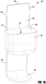
Figure 1A is a perspective view of an exemplary dispenser with a closed cover; -
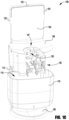
Figure 1B is a perspective view of an exemplary refill unit installed in an exemplary dispenser with a closed cover; -
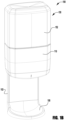
Figure 1C is a perspective view of an exemplary dispenser with an open cover; -
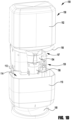
Figure 1D is a perspective view of an exemplary refill unit installed in an exemplary dispenser with an open cover; -
Figure 1E is a cross-sectional view of an exemplary refill unit installed in an exemplary dispenser with an open cover; -
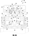
Figure 2A is a elevational view of an exemplary dispenser (with the top plate removed) with a closed latch; -
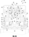
Figure 2B is a elevational view of the exemplary dispenser (with the top plate removed) ofFigure 2A with an unlocked latch; -
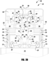
Figure 2C is a elevational view of the exemplary dispenser (with the top plate removed) ofFigure 2A with a key inserted, the actuation members locked out, and the cover locked in its closed position; and -
Figure 2D is a elevational view of the exemplary dispenser (with the top plate removed) ofFigure 2A with the actuation members locked out and the key used to unlock the cover. -
Figures 1A to 1E illustrate anexemplary dispenser 100 with asliding cover 110. The dispenser includes abase 101 that has tworails 102. Thecover 110 is slideably attached to therails 102 and is slideable between a closed position shown inFigure 1A and1B , and an open position shown inFigures 1C ,1D , and1E . In some embodiments, thebase 101 has only onerail 102. In other embodiments, thebase 101 has more than tworails 102. Thecover 110 slides downward when opened, and the cover slides upward to close the refill unit. In other embodiments, the cover may even be split into two or more portions, each sliding in a different direction when the cover is opened. - The
dispenser 100 includes a latch (not shown) that engages thecover 110. InFigures 1A-1D , the latch (not shown, but described in detail with respect toFigures 2A-2C ) is covered by atop plate 104 of thebase 101. The latch (not shown) is biased to remain closed, and is opened by pressing on anactuation member 122. Releasing theactuation member 122 allows the latch (not shown) to close. The closed latch retains thecover 110 in its closed position. Opening the latch allows thecover 110 to slide to its open position. When open, thecover 110 can be closed regardless of the state of the latch. The latch can be locked so it cannot be opened by pressing on theactuation member 122. Inserting a key (not shown) into akey aperture 103 in thebase 101 locks the latch. - In some embodiments, a
base 106 at least partially supports a refill unit 150 (Figs. 1B ,1D ,1E ) which is received in areceptacle 107. When closed, thecover 110 andrefill unit 150 conceal thebase 106. Opening thecover 110 provides access toreceptacle 107 so that arefill unit 150 can be installed in thereceptacle 107 of thedispenser 100. When therefill unit 150 is installed in thedispenser 100, apump 154 of therefill unit 150 is engaged by adrive unit 130 of thedispenser 100. Thedrive unit 130 actuates thepump 154 to dispense liquid or foam from therefill unit 150. Therefill unit 150 is inserted (and removed) along a horizontal axis. Abattery pod 160 is located onrefill unit 150 and engages abattery receptacle 162 of thedispenser 100. Thecover 110 is then closed to cover at least a portion of therefill unit 150. Thecover 110 prevents therefill unit 150 from being removed when thecover 110 is closed. In some embodiments, the cover covers thepump 154 and/oroutlet nozzle 156 of arefill unit 150. In some embodiments, thecover 110 covers theentire refill unit 150, including apump 154 and/ornozzle 156, and acontainer 152. In some embodiments, thecover 110 covers a portion of thepump 154 and/orcontainer 152. - The
cover 110 includesslides 112 that engage therails 102 of thebase 101 and allow thecover 110 to slide between the closed and open positions. Thecover 110 forms acavity 114 that encloses the lower portion of therefill unit 150 when it is installed in thedispenser 100. Anaperture 116 in the bottom of thecover 110 allows fluid or foam dispensed from therefill unit 150 to exit thedispenser 110 for use. Anoptional drip tray 108 is attached to thebase 101 below the mountingportion 106 and thecover 110 to catch unused fluid dispensed from therefill unit 150. -
Figures 2A ,2B ,2C , and2D illustrate anexemplary dispenser 200 having alatch 201.Latch 201 is an exemplary embodiment of the latch called out above. Thelatch 201 is exposed by removing thetop plate 104 to more clearly show the components of thelatch 201. Thelatch 201 is shown latched inFigure 2A and unlatched inFigure 2B . Theactuators Figures 2C and2D . Thelatch 201 is shown latched inFigure 2C and unlatched inFigure 2D . - In addition to the
latch 201, thedispenser 200 includes aback plate 202 and acover 210. Thelatch 201 includes arelease member 220, twoactuation members lockout member 250.Openings 203 in the back plate allow thedispenser 200 to be mounted on a wall or other surface with screws (not shown) or other fastening means. In some embodiments,dispenser 200 is secured to a mounting surface by two sided tape (not shown). Therelease member 220, twoactuation members lockout member 250 of thelatch 201 are retained in theback plate 202 byretainers 204. Theretainers 204 allow these components move in a substantially linear direction. In some embodiments, these components may rotate, move toward, or away from theback plate 202 during operation of thelatch 201. - The
cover 210 includesslides 212 that slide along therails 211 of thedispenser 200, allowing thecover 210 to slide between a closed position and an open position. Eachslide 212 has acatch portion 214 with alatch aperture 216. - The
release member 220 includes acammed surface 222 that is angled,bolt members 224, andspring members 226. Therelease member 220 is moveable between a closed position (Figs. 2A ,2C ) and an open position (Figs. 2B ,2D ). Engagement of thecammed surface 222 byactuation member 230 and/or 240 moves therelease member 220 downward from the closed position to the open position. In the open position, theresilient leg portions 225 of thebolt members 224 slide alongprojections 205 extending from theback plate 202 and thebolt members 224 are drawn inward along the bolt channels 206 and out oflock apertures 216 ofslides 212, unlatching thecover 210 so that it may be slid downward. - Simultaneously, the
spring members 226 are forced againstprojections 207 and elastically deformed, resisting the downward force exerted on therelease member 220. When the force applied to thecammed surface 222 is removed, thespring members 226 return to their original shape, pushing therelease member 220 upward to its closed position, thereby extending thebolt members 224 outward through the bolt channels 206. When thecover 210 is moved back upward to its home position,bolt members 224 slide intolatch apertures 216, latching thecover 210 in place. Thelegs 225 of thebolt members 224 also bias against theprojections 205, helping therelease member 220 return to its latched position. - When the
release member 220 is in the latched position, thebolt members 224 extend into thelatch apertures 216 of thecover 210, retaining thecover 210 in its closed position. When therelease member 220 is moved to its unlatched position, thebolt members 224 are retracted from thelatch apertures 216 and thecover 210 can be opened. Therelease member 220 is biased to its latched position after thecover 210 has been opened and does not need to be manually moved again to close thecover 210. Theslides 212 of thecover 210 includeinclined portions 218 so that thecover 210 can be closed without movingactuation member 230 and/or 240. As thecover 210 moves upward, theinclined portions 218 of theslides 212 cause thebolt members 224 to retract into the bolt channels 206 so thecover 210 can be closed. When thecover 210 reaches the closed position, thebolt members 224 return to their latched position and engage thelatch apertures 216 to secure thecover 210 in place. - The
actuation members spring members actuation members Figs. 2A ,2C ,2D ) and an actuated position (Fig. 2B ). Theactuation members actuators actuation members surfaces cammed surface 222 of therelease member 220, moving therelease member 220 from the latched to the unlatched position. Thespring members projections 207 and elastically deformed, resisting the inward force exerted on theactuators actuators spring members actuation members cammed surface 222 of therelease member 220. Thelatch 201 may be actuated by either one or both of theactuation members - To prevent tampering with a refill unit (not shown) installed in the
dispenser 200 by an unauthorized person, theactuation members lockout member 250. Locking theactuation members actuation members release member 220. Thelockout member 250 includes a blockingportion 252, afirst opening 254, asecond opening 256, and at least one spring member 258. Thelockout member 250 is moveable between an unlocked position (Figs. 2A ,2B ), a locked position (Fig. 2C ), and an actuating position (Fig. 2D ). In the unlocked position, aninclined protrusion 208 from theback plate 202 is located within thefirst opening 254 and restricts movement of thelockout member 250 so theactuation members actuation members key aperture 209 in thedispenser 200 to push thelockout member 250 downward to its locked position, overcoming the resistance provided by theinclined protrusion 208. In the locked position, theinclined protrusion 208 is located in thesecond opening 254 of thelockout member 250, preventing thelockout member 250 from returning to the unlocked position. - In the locked position, the
lockout member 250 is disposed between the twoactuation members latch 201. Thelatch 201 can still be unlatched, however, by inserting the key 251 into thekey aperture 209 and pushing thelockout member 250 into an actuating position beyond its locked position. To unlatch thelatch 201 while it is locked, the key 251 is inserted through thekey aperture 209 to push thelockout member 250 downward until it engages theactuation surface 223 of therelease member 220. Further downward movement of the key 251 pushes therelease member 220 downward from its closed to open position, thereby unlatching thelatch 201 and releasing thecover 210. The downward movement of thelockout member 250 forces the spring members 258 against theprotrusions 207 causing them to elastically deform. When the force applied to the key 251 is removed, the spring members 258 return to their original shape, pushing thelockout member 250 back to its locked position. Therelease member 220 is then free to return to its latched position, latching thelatch 201.
Claims (15)
- A dispenser (100) comprising:a refill unit (150) having a battery pod (160);a receptacle (107) on the dispenser (100) for receiving the battery pod (160); anda sliding cover (110);wherein the sliding cover (110) slides downward to allow access to the refill unit (150); andwherein the sliding cover (110) slides upward to close and to prevent the refill unit (150) from being removed.
- The dispenser (100) of claim 1 further comprising:at least one rail (102) having a first end and a second end;a latch (201) disposed at the first end of the rail (102);wherein the sliding cover (110) is slideable along the at least one rail (102) between a closed position at the first end of the rail (102) and an open position at the second end of the rail (102); andwherein the refill unit (150) further comprises:a container (152);a pump (154); anda nozzle (156);wherein when the cover (110) is in the closed position, the cover (110) covers at least a portion of the refill unit (150) and leaves a portion of the refill unit (150) exposed;wherein the cover (110) is held in the closed position by the latch (201).
- The dispenser (100) of claim 2, wherein the latch (201) further comprises:at least one actuation member (230, 240); anda release member (220);wherein movement of the at least one actuation member (230, 240) moves the release member (220).
- The dispenser (100) of claim 3, wherein the release member (220) may be moved without the actuation member (230, 240) moving.
- The dispenser (100) of claim 4, further comprising a lockout member (250) moveable between a locked state and an unlocked state.
- The dispenser (100) of claim 5, wherein the lockout member (250) locks the at least one actuation member (230, 240).
- The dispenser (100) of claim 6, wherein the lockout member (250) moves the release member (220).
- The dispenser (100) of claim 1 further comprising a battery receptacle (162) that engages the battery pod (160).
- The dispenser (100) of claim 1 wherein opening the cover (110) provides access to the receptacle (107) so that the refill unit (150) can be installed in the receptacle (107).
- The dispenser (100) of claim 3 wherein the release member (220) includes a cammed surface (222) that is angled, bolt members (224) and spring members (226).
- The dispenser (100) of claim 1 further comprising a base (106) for at last partially supporting the refill unit (150).
- The dispenser (100) of claim 3 comprising two actuation members (230, 240).
- The dispenser (100) of claim 3 wherein the release member (220) is biased to its latched position.
- The dispenser (100) of claim 3 further comprising a key (251) for moving the lockout member (250) downward to its locked position.
- The dispenser (100) of claim 3 wherein the at least one actuation member (230, 240) includes a spring member (234, 244).
Applications Claiming Priority (3)
| Application Number | Priority Date | Filing Date | Title |
|---|---|---|---|
| US201562238897P | 2015-10-08 | 2015-10-08 | |
| PCT/US2016/055252 WO2017062325A1 (en) | 2015-10-08 | 2016-10-04 | Sliding cover of refillable dispenser |
| EP16782361.6A EP3359006B1 (en) | 2015-10-08 | 2016-10-04 | Sliding cover of refillable dispenser |
Related Parent Applications (2)
| Application Number | Title | Priority Date | Filing Date |
|---|---|---|---|
| EP16782361.6A Division-Into EP3359006B1 (en) | 2015-10-08 | 2016-10-04 | Sliding cover of refillable dispenser |
| EP16782361.6A Division EP3359006B1 (en) | 2015-10-08 | 2016-10-04 | Sliding cover of refillable dispenser |
Publications (2)
| Publication Number | Publication Date |
|---|---|
| EP3827721A1 EP3827721A1 (en) | 2021-06-02 |
| EP3827721B1 true EP3827721B1 (en) | 2023-12-27 |
Family
ID=57145051
Family Applications (2)
| Application Number | Title | Priority Date | Filing Date |
|---|---|---|---|
| EP16782361.6A Active EP3359006B1 (en) | 2015-10-08 | 2016-10-04 | Sliding cover of refillable dispenser |
| EP21152026.7A Active EP3827721B1 (en) | 2015-10-08 | 2016-10-04 | Slide open refillable dispenser |
Family Applications Before (1)
| Application Number | Title | Priority Date | Filing Date |
|---|---|---|---|
| EP16782361.6A Active EP3359006B1 (en) | 2015-10-08 | 2016-10-04 | Sliding cover of refillable dispenser |
Country Status (6)
| Country | Link |
|---|---|
| US (3) | US10149575B2 (en) |
| EP (2) | EP3359006B1 (en) |
| JP (2) | JP6840135B2 (en) |
| AU (2) | AU2016333784B2 (en) |
| CA (1) | CA3000720A1 (en) |
| WO (1) | WO2017062325A1 (en) |
Families Citing this family (21)
| Publication number | Priority date | Publication date | Assignee | Title |
|---|---|---|---|---|
| USD781064S1 (en) * | 2016-04-14 | 2017-03-14 | Gojo Industries, Inc. | Product dispenser |
| USD811770S1 (en) * | 2016-06-21 | 2018-03-06 | Gojo Industries, Inc. | Wall mounted dispenser cabinet |
| USD802329S1 (en) | 2016-06-21 | 2017-11-14 | Gojo Industries, Inc. | Wall mounted dispenser cabinet |
| USD862112S1 (en) | 2016-09-21 | 2019-10-08 | Gojo Industries, Inc. | Dispenser |
| USD815457S1 (en) | 2016-10-31 | 2018-04-17 | Gojo Industries, Inc. | Wall mounted dispenser cabinet |
| USD809821S1 (en) | 2016-10-31 | 2018-02-13 | Gojo Industries, Inc. | Wall mounted dispenser cabinet |
| USD820614S1 (en) | 2016-11-28 | 2018-06-19 | Gojo Industries, Inc. | Wall mounted dispenser cabinet |
| US11156554B2 (en) * | 2017-10-09 | 2021-10-26 | Pathspot Technologies, Inc. | Systems and methods for detection of contaminants on surfaces |
| USD846299S1 (en) | 2017-10-30 | 2019-04-23 | Gojo Industries, Inc. | Touch-free dispenser cabinet |
| USD856023S1 (en) | 2017-10-30 | 2019-08-13 | Gojo Industries, Inc. | Touch-free dispenser cabinet |
| USD846298S1 (en) | 2017-10-30 | 2019-04-23 | Gojo Industries, Inc. | Touch-free dispenser cabinet |
| USD876253S1 (en) | 2018-03-01 | 2020-02-25 | Essity Hygiene And Health Aktiebolag | Movement sensor |
| USD955780S1 (en) * | 2019-12-04 | 2022-06-28 | Clean Handle Ab | Disinfection apparatus |
| EP4149335A1 (en) | 2020-05-14 | 2023-03-22 | Gojo Industries, Inc. | Dispensers and dispenser systems for securely controlling a plurality of dose sizes |
| US11972680B2 (en) * | 2020-06-12 | 2024-04-30 | Gojo Industries, Inc. | Base for table top sanitizer dispensing bottles and dispenser bottles |
| CA3195641A1 (en) * | 2020-10-14 | 2022-04-21 | Sofia HODOSSY | An adaptor assembly for a fluid dispensing system |
| USD966739S1 (en) * | 2021-01-19 | 2022-10-18 | Dermey Commodity Co., Ltd. | Dispenser for liquid soap |
| USD975469S1 (en) * | 2021-02-10 | 2023-01-17 | Huonker Gmbh | Disinfectant dispenser |
| US11805951B2 (en) | 2021-02-22 | 2023-11-07 | Gojo Industries, Inc. | Foam dispensers having turbine air/liquid displacement pump combination |
| US11744412B2 (en) | 2021-10-07 | 2023-09-05 | Deb Ip Limited | Dispenser system |
| US11744413B2 (en) | 2021-10-07 | 2023-09-05 | Deb Ip Limited | Dispenser assembly |
Family Cites Families (23)
| Publication number | Priority date | Publication date | Assignee | Title |
|---|---|---|---|---|
| US4722372A (en) * | 1985-08-02 | 1988-02-02 | Louis Hoffman Associates Inc. | Electrically operated dispensing apparatus and disposable container useable therewith |
| US5465877A (en) * | 1992-09-08 | 1995-11-14 | Gojo Industries, Inc. | Adjustable stroke pump dispenser |
| US5379917A (en) * | 1993-03-01 | 1995-01-10 | Fresh Products, Inc. | Dual soap and fragrance dispenser |
| US5992698A (en) * | 1995-08-07 | 1999-11-30 | Ecolab Inc. | Liquid soap dispenser |
| US5897031A (en) * | 1996-06-21 | 1999-04-27 | Minnesota Mining And Manufacturing Company | Dispenser for antimicrobial liquids |
| US5810204A (en) * | 1996-10-15 | 1998-09-22 | James River Corporation | Apparatus for dispensing liquid soap or other liquids |
| US7798370B2 (en) * | 2003-10-25 | 2010-09-21 | Gojo Industries, Inc. | Universal collar key |
| US7527178B2 (en) * | 2003-12-30 | 2009-05-05 | Kimberly-Clark Worldwide, Inc. | Electronic viscous liquid dispenser |
| CA2477584C (en) * | 2004-08-12 | 2011-07-26 | Hygiene-Technik Inc. | Disposable dispenser |
| US7270250B2 (en) * | 2004-08-30 | 2007-09-18 | Hygiene-Tecknik Inc. | Disposable dispenser |
| CA2496415C (en) * | 2005-02-09 | 2013-06-18 | Hygiene-Technik Inc. | Dispenser with side mounted activation levers |
| CA2496412C (en) * | 2005-02-09 | 2013-06-18 | Hygiene-Technik Inc. | Fluid dispenser lock defeater |
| US7299951B2 (en) * | 2005-03-08 | 2007-11-27 | Ecolab Inc. | Foot activated dispenser |
| US7637391B2 (en) * | 2006-09-01 | 2009-12-29 | Joseph S Kanfer | Cover release mechanism for a dispenser |
| CA2633837C (en) * | 2008-06-05 | 2015-05-12 | Gotohti.Com Inc. | Spring force adjustment system |
| JP5129664B2 (en) * | 2008-06-25 | 2013-01-30 | 株式会社シブタニ | Fire door locking device and locking device |
| CA2645953A1 (en) * | 2008-12-08 | 2010-06-08 | Gotohti.Com Inc. | Engagement flange for fluid dispenser pump piston |
| US8245877B2 (en) * | 2009-07-22 | 2012-08-21 | Gotohti.Com Inc. | Dispenser with palm reader |
| US20130020351A1 (en) * | 2011-07-21 | 2013-01-24 | Gojo Industries, Inc. | Dispenser with optical keying system |
| KR101409211B1 (en) * | 2012-07-17 | 2014-06-20 | 주식회사 진텍 | A cover of cock for water tank of hot/cold water purifier |
| CA2929959A1 (en) | 2013-11-08 | 2015-05-14 | Gojo Industries, Inc. | Modular adaptor for monitoring dispenser activity |
| CA2839615C (en) * | 2014-01-06 | 2021-04-20 | Heiner Ophardt | Dispenser cover retention arrangement |
| US20150235549A1 (en) * | 2014-02-20 | 2015-08-20 | Debmed Usa Llc | Electronically monitored and portable point-of-care hand hygiene dispenser having security features |
-
2016
- 2016-09-30 US US15/281,832 patent/US10149575B2/en active Active
- 2016-10-04 JP JP2018515274A patent/JP6840135B2/en active Active
- 2016-10-04 WO PCT/US2016/055252 patent/WO2017062325A1/en active Application Filing
- 2016-10-04 CA CA3000720A patent/CA3000720A1/en active Pending
- 2016-10-04 AU AU2016333784A patent/AU2016333784B2/en active Active
- 2016-10-04 EP EP16782361.6A patent/EP3359006B1/en active Active
- 2016-10-04 EP EP21152026.7A patent/EP3827721B1/en active Active
-
2018
- 2018-12-04 US US16/209,316 patent/US10485385B2/en active Active
-
2019
- 2019-11-22 US US16/691,826 patent/US10986966B2/en active Active
-
2021
- 2021-02-16 JP JP2021022692A patent/JP7154329B2/en active Active
-
2022
- 2022-03-04 AU AU2022201536A patent/AU2022201536B2/en active Active
Also Published As
| Publication number | Publication date |
|---|---|
| AU2022201536B2 (en) | 2024-03-07 |
| CA3000720A1 (en) | 2017-04-13 |
| EP3359006B1 (en) | 2021-02-24 |
| US10485385B2 (en) | 2019-11-26 |
| JP6840135B2 (en) | 2021-03-10 |
| EP3359006A1 (en) | 2018-08-15 |
| JP2018531062A (en) | 2018-10-25 |
| AU2016333784B2 (en) | 2021-12-16 |
| US10986966B2 (en) | 2021-04-27 |
| AU2022201536A1 (en) | 2022-03-24 |
| US20200163496A1 (en) | 2020-05-28 |
| JP2021098031A (en) | 2021-07-01 |
| US10149575B2 (en) | 2018-12-11 |
| AU2016333784A1 (en) | 2018-05-10 |
| US20170100001A1 (en) | 2017-04-13 |
| WO2017062325A1 (en) | 2017-04-13 |
| EP3827721A1 (en) | 2021-06-02 |
| JP7154329B2 (en) | 2022-10-17 |
| US20190099047A1 (en) | 2019-04-04 |
Similar Documents
| Publication | Publication Date | Title |
|---|---|---|
| EP3827721B1 (en) | Slide open refillable dispenser | |
| JP2018531062A6 (en) | Refillable dispenser sliding cover | |
| US9279273B2 (en) | Lock | |
| TWI502126B (en) | Dispenser housing with locking mechanism | |
| EP1702547B1 (en) | Fluid dispenser lock defeater | |
| KR20140050063A (en) | Dispenser lockout mechanism | |
| US5476220A (en) | Lockable mailbox apparatus | |
| US11160423B2 (en) | Dispenser | |
| KR101631569B1 (en) | Lock handle device for door | |
| KR0131801Y1 (en) | Unlocking position restraint type latch device | |
| CN114190686A (en) | Locking base for dispensers and the like | |
| TW201712206A (en) | Fitting for a sliding door and method for mounting a sliding door | |
| WO2020033994A1 (en) | Sliding body restrictor | |
| KR830002080Y1 (en) | Bathroom storage locker | |
| KR20100009519U (en) | Furniture locking device | |
| JP3181194U (en) | Fixing tool for door opening prevention tool | |
| CN116324106A (en) | Locking device for movable furniture parts | |
| ZA200802107B (en) | A locking mechanism for a housing | |
| JPH11240494A (en) | Lock mechanism for slide type hanger rod | |
| KR20170012940A (en) | Door locking apparatus | |
| WO2011075759A1 (en) | Push lock |
Legal Events
| Date | Code | Title | Description |
|---|---|---|---|
| PUAI | Public reference made under article 153(3) epc to a published international application that has entered the european phase |
Free format text: ORIGINAL CODE: 0009012 |
|
| STAA | Information on the status of an ep patent application or granted ep patent |
Free format text: STATUS: THE APPLICATION HAS BEEN PUBLISHED |
|
| AC | Divisional application: reference to earlier application |
Ref document number: 3359006 Country of ref document: EP Kind code of ref document: P |
|
| AK | Designated contracting states |
Kind code of ref document: A1 Designated state(s): AL AT BE BG CH CY CZ DE DK EE ES FI FR GB GR HR HU IE IS IT LI LT LU LV MC MK MT NL NO PL PT RO RS SE SI SK SM TR |
|
| STAA | Information on the status of an ep patent application or granted ep patent |
Free format text: STATUS: REQUEST FOR EXAMINATION WAS MADE |
|
| 17P | Request for examination filed |
Effective date: 20211201 |
|
| RBV | Designated contracting states (corrected) |
Designated state(s): AL AT BE BG CH CY CZ DE DK EE ES FI FR GB GR HR HU IE IS IT LI LT LU LV MC MK MT NL NO PL PT RO RS SE SI SK SM TR |
|
| GRAP | Despatch of communication of intention to grant a patent |
Free format text: ORIGINAL CODE: EPIDOSNIGR1 |
|
| STAA | Information on the status of an ep patent application or granted ep patent |
Free format text: STATUS: GRANT OF PATENT IS INTENDED |
|
| INTG | Intention to grant announced |
Effective date: 20230517 |
|
| P01 | Opt-out of the competence of the unified patent court (upc) registered |
Effective date: 20230512 |
|
| GRAS | Grant fee paid |
Free format text: ORIGINAL CODE: EPIDOSNIGR3 |
|
| GRAA | (expected) grant |
Free format text: ORIGINAL CODE: 0009210 |
|
| STAA | Information on the status of an ep patent application or granted ep patent |
Free format text: STATUS: THE PATENT HAS BEEN GRANTED |
|
| AC | Divisional application: reference to earlier application |
Ref document number: 3359006 Country of ref document: EP Kind code of ref document: P |
|
| AK | Designated contracting states |
Kind code of ref document: B1 Designated state(s): AL AT BE BG CH CY CZ DE DK EE ES FI FR GB GR HR HU IE IS IT LI LT LU LV MC MK MT NL NO PL PT RO RS SE SI SK SM TR |
|
| REG | Reference to a national code |
Ref country code: GB Ref legal event code: FG4D |
|
| REG | Reference to a national code |
Ref country code: CH Ref legal event code: EP |
|
| REG | Reference to a national code |
Ref country code: DE Ref legal event code: R096 Ref document number: 602016085089 Country of ref document: DE |
|
| REG | Reference to a national code |
Ref country code: IE Ref legal event code: FG4D |
|
| PG25 | Lapsed in a contracting state [announced via postgrant information from national office to epo] |
Ref country code: GR Free format text: LAPSE BECAUSE OF FAILURE TO SUBMIT A TRANSLATION OF THE DESCRIPTION OR TO PAY THE FEE WITHIN THE PRESCRIBED TIME-LIMIT Effective date: 20240328 |
|
| REG | Reference to a national code |
Ref country code: LT Ref legal event code: MG9D |
|
| PG25 | Lapsed in a contracting state [announced via postgrant information from national office to epo] |
Ref country code: LT Free format text: LAPSE BECAUSE OF FAILURE TO SUBMIT A TRANSLATION OF THE DESCRIPTION OR TO PAY THE FEE WITHIN THE PRESCRIBED TIME-LIMIT Effective date: 20231227 |
|
| PG25 | Lapsed in a contracting state [announced via postgrant information from national office to epo] |
Ref country code: ES Free format text: LAPSE BECAUSE OF FAILURE TO SUBMIT A TRANSLATION OF THE DESCRIPTION OR TO PAY THE FEE WITHIN THE PRESCRIBED TIME-LIMIT Effective date: 20231227 |
|
| PG25 | Lapsed in a contracting state [announced via postgrant information from national office to epo] |
Ref country code: LT Free format text: LAPSE BECAUSE OF FAILURE TO SUBMIT A TRANSLATION OF THE DESCRIPTION OR TO PAY THE FEE WITHIN THE PRESCRIBED TIME-LIMIT Effective date: 20231227 Ref country code: GR Free format text: LAPSE BECAUSE OF FAILURE TO SUBMIT A TRANSLATION OF THE DESCRIPTION OR TO PAY THE FEE WITHIN THE PRESCRIBED TIME-LIMIT Effective date: 20240328 Ref country code: FI Free format text: LAPSE BECAUSE OF FAILURE TO SUBMIT A TRANSLATION OF THE DESCRIPTION OR TO PAY THE FEE WITHIN THE PRESCRIBED TIME-LIMIT Effective date: 20231227 Ref country code: ES Free format text: LAPSE BECAUSE OF FAILURE TO SUBMIT A TRANSLATION OF THE DESCRIPTION OR TO PAY THE FEE WITHIN THE PRESCRIBED TIME-LIMIT Effective date: 20231227 Ref country code: BG Free format text: LAPSE BECAUSE OF FAILURE TO SUBMIT A TRANSLATION OF THE DESCRIPTION OR TO PAY THE FEE WITHIN THE PRESCRIBED TIME-LIMIT Effective date: 20240327 |
|
| REG | Reference to a national code |
Ref country code: NL Ref legal event code: MP Effective date: 20231227 |