EP3827552B1 - Process-efficient generation of data records for data communications involving groups or aggregates of iot devices - Google Patents
Process-efficient generation of data records for data communications involving groups or aggregates of iot devices Download PDFInfo
- Publication number
- EP3827552B1 EP3827552B1 EP19753504.0A EP19753504A EP3827552B1 EP 3827552 B1 EP3827552 B1 EP 3827552B1 EP 19753504 A EP19753504 A EP 19753504A EP 3827552 B1 EP3827552 B1 EP 3827552B1
- Authority
- EP
- European Patent Office
- Prior art keywords
- data
- aggregation
- group
- request
- ues
- Prior art date
- Legal status (The legal status is an assumption and is not a legal conclusion. Google has not performed a legal analysis and makes no representation as to the accuracy of the status listed.)
- Active
Links
Images


Classifications
-
- H—ELECTRICITY
- H04—ELECTRIC COMMUNICATION TECHNIQUE
- H04M—TELEPHONIC COMMUNICATION
- H04M15/00—Arrangements for metering, time-control or time indication ; Metering, charging or billing arrangements for voice wireline or wireless communications, e.g. VoIP
- H04M15/70—Administration or customization aspects; Counter-checking correct charges
- H04M15/765—Linked or grouped accounts, e.g. of users or devices
-
- H—ELECTRICITY
- H04—ELECTRIC COMMUNICATION TECHNIQUE
- H04L—TRANSMISSION OF DIGITAL INFORMATION, e.g. TELEGRAPHIC COMMUNICATION
- H04L12/00—Data switching networks
- H04L12/02—Details
- H04L12/14—Charging, metering or billing arrangements specially adapted for data communications, e.g. authentication, authorisation and accounting [AAA] framework
- H04L12/1403—Architecture for metering, charging or billing
-
- H—ELECTRICITY
- H04—ELECTRIC COMMUNICATION TECHNIQUE
- H04L—TRANSMISSION OF DIGITAL INFORMATION, e.g. TELEGRAPHIC COMMUNICATION
- H04L12/00—Data switching networks
- H04L12/02—Details
- H04L12/14—Charging, metering or billing arrangements specially adapted for data communications, e.g. authentication, authorisation and accounting [AAA] framework
- H04L12/1403—Architecture for metering, charging or billing
- H04L12/1407—Policy-and-charging control [PCC] architecture
-
- H—ELECTRICITY
- H04—ELECTRIC COMMUNICATION TECHNIQUE
- H04L—TRANSMISSION OF DIGITAL INFORMATION, e.g. TELEGRAPHIC COMMUNICATION
- H04L12/00—Data switching networks
- H04L12/02—Details
- H04L12/14—Charging, metering or billing arrangements specially adapted for data communications, e.g. authentication, authorisation and accounting [AAA] framework
- H04L12/1428—Invoice generation, e.g. customization, lay-out, database processing, algorithms for calculating the bill or formatting invoices as WWW pages
-
- H—ELECTRICITY
- H04—ELECTRIC COMMUNICATION TECHNIQUE
- H04L—TRANSMISSION OF DIGITAL INFORMATION, e.g. TELEGRAPHIC COMMUNICATION
- H04L43/00—Arrangements for monitoring or testing data switching networks
- H04L43/06—Generation of reports
- H04L43/065—Generation of reports related to network devices
-
- H—ELECTRICITY
- H04—ELECTRIC COMMUNICATION TECHNIQUE
- H04M—TELEPHONIC COMMUNICATION
- H04M15/00—Arrangements for metering, time-control or time indication ; Metering, charging or billing arrangements for voice wireline or wireless communications, e.g. VoIP
- H04M15/41—Billing record details, i.e. parameters, identifiers, structure of call data record [CDR]
-
- H—ELECTRICITY
- H04—ELECTRIC COMMUNICATION TECHNIQUE
- H04M—TELEPHONIC COMMUNICATION
- H04M15/00—Arrangements for metering, time-control or time indication ; Metering, charging or billing arrangements for voice wireline or wireless communications, e.g. VoIP
- H04M15/43—Billing software details
-
- H—ELECTRICITY
- H04—ELECTRIC COMMUNICATION TECHNIQUE
- H04M—TELEPHONIC COMMUNICATION
- H04M15/00—Arrangements for metering, time-control or time indication ; Metering, charging or billing arrangements for voice wireline or wireless communications, e.g. VoIP
- H04M15/44—Augmented, consolidated or itemized billing statement or bill presentation
-
- H—ELECTRICITY
- H04—ELECTRIC COMMUNICATION TECHNIQUE
- H04M—TELEPHONIC COMMUNICATION
- H04M15/00—Arrangements for metering, time-control or time indication ; Metering, charging or billing arrangements for voice wireline or wireless communications, e.g. VoIP
- H04M15/58—Arrangements for metering, time-control or time indication ; Metering, charging or billing arrangements for voice wireline or wireless communications, e.g. VoIP based on statistics of usage or network monitoring
-
- H—ELECTRICITY
- H04—ELECTRIC COMMUNICATION TECHNIQUE
- H04M—TELEPHONIC COMMUNICATION
- H04M15/00—Arrangements for metering, time-control or time indication ; Metering, charging or billing arrangements for voice wireline or wireless communications, e.g. VoIP
- H04M15/64—On-line charging system [OCS]
-
- H—ELECTRICITY
- H04—ELECTRIC COMMUNICATION TECHNIQUE
- H04M—TELEPHONIC COMMUNICATION
- H04M15/00—Arrangements for metering, time-control or time indication ; Metering, charging or billing arrangements for voice wireline or wireless communications, e.g. VoIP
- H04M15/65—Off-line charging system
-
- H—ELECTRICITY
- H04—ELECTRIC COMMUNICATION TECHNIQUE
- H04M—TELEPHONIC COMMUNICATION
- H04M15/00—Arrangements for metering, time-control or time indication ; Metering, charging or billing arrangements for voice wireline or wireless communications, e.g. VoIP
- H04M15/66—Policy and charging system
-
- H—ELECTRICITY
- H04—ELECTRIC COMMUNICATION TECHNIQUE
- H04M—TELEPHONIC COMMUNICATION
- H04M15/00—Arrangements for metering, time-control or time indication ; Metering, charging or billing arrangements for voice wireline or wireless communications, e.g. VoIP
- H04M15/70—Administration or customization aspects; Counter-checking correct charges
- H04M15/77—Administration or customization aspects; Counter-checking correct charges involving multiple accounts per user
- H04M15/771—Administration or customization aspects; Counter-checking correct charges involving multiple accounts per user per terminal or location, e.g. mobile device with multiple directory numbers
-
- H—ELECTRICITY
- H04—ELECTRIC COMMUNICATION TECHNIQUE
- H04M—TELEPHONIC COMMUNICATION
- H04M15/00—Arrangements for metering, time-control or time indication ; Metering, charging or billing arrangements for voice wireline or wireless communications, e.g. VoIP
- H04M15/82—Criteria or parameters used for performing billing operations
- H04M15/8214—Data or packet based
-
- H—ELECTRICITY
- H04—ELECTRIC COMMUNICATION TECHNIQUE
- H04W—WIRELESS COMMUNICATION NETWORKS
- H04W4/00—Services specially adapted for wireless communication networks; Facilities therefor
- H04W4/24—Accounting or billing
Definitions
- the present disclosure relates generally to a method, computer program and apparatus for use in generating data records for data communications involving groups or aggregates of mobile devices, such as Internet of Things (IoT) devices, operative in mobile or wireless networks.
- IoT Internet of Things
- IoT Internet of Things
- a network element collects, within a time window, charging information of a plurality of user equipments belonging to a same group, aggregates the charging information to obtain a charging aggregation result, and sends the charging aggregation result to a corresponding device in said system.
- the charging system receives a plurality of pieces of aggregated charging information and time windows sent by a network element in the system, wherein each piece of charging information respectively corresponds to one of the time windows, and aggregates the plurality of pieces of aggregated charging information based on the time windows and the group(s) and/or sub-group(s) to which the user equipments belong, to generate charging data record(s), wherein the time windows and the user equipments correspond to the plurality of pieces of aggregated charging information.
- UEs user equipment
- IoT Internet of Things
- a request which includes data indicative of a network resource usage event of the UE is received and the data are stored in association with the group or aggregation ID.
- the data indicative of the network resource usage events associated with the group or aggregation ID are aggregated.
- a request for generating a data record based on the aggregated data is then sent to a data function for generating a data record.
- the generated data record may be stored for subsequent retrieval, for reporting, analysis, billing, and/or communications management.
- the predetermined condition may be or include, as examples, an expiration of a time period, or a detection of a volume limit for data transfers involving the plurality of UEs.
- the technique may be performed by one or more network nodes or functions of a mobile network.
- the one or more network nodes or functions comprise a charging data function (CDF) which includes an aggregation function, where the request including the data indicative of the network resource usage event is a charging data request from a charging trigger function (CTF), and the request for generating a data record is a request for generating a charging data record (CDR).
- CDF charging data function
- CTF charging trigger function
- CDR charging data record
- the CDR may sent via a charging gateway function (CGF) for receipt at a billing domain entity.
- CGF charging gateway function
- a system of the present disclosure may include one or more network nodes of a control plane (CP) entity for data transfer charging (e.g. a control plane data transfer charging node or "CPCN").
- the one or more network nodes may have a CTF and a CDF which may include an aggregation function.
- the CTF may be configured to, for each one of a plurality of UEs associated with a group or aggregation ID, send to the CDF (or the aggregation function thereof) a charging data request which includes charging data indicative of a charging event of the UE.
- the CDF (or the aggregation function thereof) may be configured to, for each one of the plurality of UEs associated with the group or aggregation ID, receive from the CTF the request which includes the charging data indicative of the network resource usage event and store the charging data in association with the group or aggregation ID.
- the aggregation function may be configured to, in response to identifying a predetermined condition, aggregate the charging data indicative of the charging events associated with the group or aggregation ID, and provide to the CDF a charging data record generation request for generating a CDR based on the aggregated data.
- the CDR may sent via a CGF for receipt at a billing domain entity.
- a request for a data transfer between an AS and a plurality of UEs of a group associated with a group ID is received.
- data are communicated between the AS and the plurality of UEs of the group associated with the group ID.
- a request for generating a data record for the data transfer for the plurality of UEs of the group associated with the group ID is sent to a system for generating data records.
- the request for generating the data record may include, for example, an attribute value pair (AVP) indicating a volume of the data transfer for the plurality of UEs of the group, one or more AVPs indicating success or partial failures in the data transfer for the plurality of UEs of the group, and/or an AVP indicating an identity of a CP entity for mobility management used in the data transfer for the plurality of UEs of the group.
- AVP attribute value pair
- the request for generating the data record may be a charging data request for generating a CDR, where the CDR is sent via a CGF for receipt at a billing domain entity.
- Electronic data records may be generated for a variety of different purposes, such as for documenting communications associated with mobile devices operating in mobile (wireless) networks. Such data records may be stored for subsequent retrieval for reporting, analysis, billing, or communications management.
- IoT Internet of Things
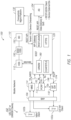
- Mobile network 110 of FIG. 1 is configured as a Fourth generation (4G), Long Term Evolution (LTE), Evolved Packet Core (EPC) based mobile network.
- Mobile network 110 includes a plurality of network nodes or entities, such as a home subscriber server (HSS) 112, a mobility management entity (MME) 114, a policy and charging rules function (PCRF) 116, a serving/packet data network (S/P) gateway (S/P GW) 118, and a service and capability exposure function (SCEF) 120.
- HSS home subscriber server
- MME mobility management entity
- PCRF policy and charging rules function
- S/P serving/packet data network gateway
- SCEF service and capability exposure function
- Mobile network 110 may further include a business support system (BSS) / operations support system (OSS) 150 and a billing domain (BD) entity 152.
- BSS business support system
- OSS operations support system
- BD billing domain
- a plurality of user equipment (UEs) 102 may access mobile network 110 via one or more base stations, such as an eNodeB (eNB) 106, for communication.
- eNB eNodeB
- SCEF 120 is one type of network node configured for exposure of services and capabilities of the mobile network 110, and for interfacing with application servers (e.g. an application server or AS 104). SCEF 120 may interface with AS 104 (e.g. with use of a REST API) for communicating data between the AS 104 and UEs 102. A connectivity management platform 130 may also be used in association with SCEF 120. Further, SCEF 120 may interface with one or more MME entities (e.g. MME 114) for non-IP data delivery (NIDD), and one or more S/P GW entities (e.g. S/P GW 118) and one or more PCRFs entities (e.g. PCRF 116) for IP data delivery.
- MME entities e.g. MME 114
- S/P GW entities e.g. S/P GW 118
- PCRFs entities e.g. PCRF 116
- a first mobile network route for data communication makes use of a T6a interface 192 for NIDD, and a second mobile network route for data communication makes use of a SGi interface 194 which terminates at SCEF 120 for IP data delivery.
- SCEF 120 is an enhanced SCEF (eSCEF) described in 3GPP TS 23.682 specifications.
- UEs 102 may include lightweight machine-to-machine (LWM2M) devices, such as a UE 102a which is a CAT-M1 device and a UE 102b which is a Narrowband (NB) IoT device.
- LWM2M lightweight machine-to-machine
- SCEF 120 may include a LWM2M server 180 configured for use with UEs that are LWM2M clients, as well as other applicable functionalities such as Constrained Application Protocol (CoAP) and Datagram Transport Layer Security (DTLS) functions.
- CoAP Constrained Application Protocol
- DTLS Datagram Transport Layer Security
- UE 102a which is a CAT-M1 device, is configured to support IP data delivery for wideband (WB) data communication, as well as NIDD for narrowband (NB) data communication.
- SCEF 120 may become aware when UE 102a connects to mobile network 110 via the PCRF / SCEF interface. At this time, SCEF 120 may create a context for UE 102a which includes its IP address as an identity.
- SCEF 120 may send MT data from AS 104 to UE 102a via S/P-GW 118 over the SGi interface 194.
- AS 102 may not even be aware how MT data is delivered to UE 102a (i.e. whether over the SGi interface 194 for IP data delivery or the T6a interface 192 for NIDD).
- NB IoT is a Low Power Wide Area Network (LPWAN) radio technology developed to enable a wide range of devices and services to be utilized in cellular bands.
- An NB IoT device such as UE 102b, is a constrained device that is not configured to support IP data delivery; rather, NB loT devices are configured to support NIDD for NB data communication.
- AS 104 may initiate a procedure that triggers an NIDD configuration procedure between SCEF 120 and HSS 112.
- an HSS record of UE 102b indicates that 120 will handle the connection to the access point name (APN).
- This information may be sent to MME 114 as part of the attachment procedure.
- MME 114 may initiate a T6a session establishment to SCEF 120.
- MT data for delivery to UE 102b may be sent over the T6a interface 192 to MME 114 based on the UE context (and/or session record) created when the T6a session establishment is performed.
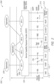
- FIG. 2 is a basic illustrative representation of SCEF reference architecture 200 of SCEF 120.
- the basis for SCEF reference architecture 200 of FIG. 2 may be found in 3 rd Generation Partnership Project (3GPP) Technical Specification (TS) 23.682 (i.e. 3GPP TS 23.682).
- SCEF 120 is shown to include one or more application programming interfaces (APIs) 206 (such as an API 208) for one or more applications 202 (such as an application 204) of the application servers.
- the one or more applications 202 may include third-party applications for third-part application servers.
- a plurality of 3GPP interfaces 210 are defined between SCEF 120 and a plurality of other network entities 212 in the mobile network.
- 3GPP interfaces relevant to techniques of the present disclosure include the T6a interface 192 for interfacing with MME 114, and Nt and Tx interfaces 196 and 198 ( FIGs. 1 and 2 ) for interfacing with PCRF 116.
- SCEF 120 is one type of network node configured for exposure of services and capabilities of mobile network 110, as well as for interfacing with application servers for communication of data via the mobile network 110.
- Another type of network node configured for exposure of services and capabilities of a mobile network is a network exposure function (NEF) node of a 5G mobile network (not shown in FIGs. 1 and 2 ).
- the NEF may interface with one or more access and mobility management (AMF) entities for NIDD, and/or one or more user plane functions (UPF) entities and one or more policy control function (PCF) entities for IP data delivery.
- AMF access and mobility management
- UPF user plane functions
- PCF policy control function
- electronic data records may be generated for network resource usage events (e.g. data communications or transfers) of the UEs 102 in mobile network 110.
- the data records may be stored for subsequent retrieval for reporting, analysis, billing, or communications management.
- billing for communications involving UEs 102 typically involves the generation of charging data records (CDRs) for chargeable events. Any chargeable event per subscriber in the form of a CDR can be monetized by the operator of mobile network 110.
- CDRs charging data records
- FIGs. 3A-3B an offline charging system (OFCS) of the mobile network is shown in relation to FIGs. 3A-3B , which includes a control plane data transfer charging node (CPCN) 302 of the mobile network of FIG. 1 .
- CPCN 302 of FIG. 3A is detailed in 3GPP documentation, such as TS 32.240 and TS 32.299.
- CPCN 302 has a plurality of network functions which include a charging trigger function (CTF) 310, a charging data function (CDF) 312, and a charging gateway function (CGF) 314.
- CTF 310 may interface with CDF 312 via an Rf interface 320
- CDF 312 may interface with CGF 314 via a Ga interface.
- CGF 314 may interface with a billing domain (BD) entity 152 via a Bx interface 324.
- CTF 310 is configured to generate and send a charging data request to CDF 312 in response to detecting a network resource usage event (e.g. a charging event) of a UE.
- CDF 312 is configured to generate a charging data record (CDR) in response to receiving a charging data request from CTF 310.
- CDF 312 is further configured to send the CDR via CGF 314 for receipt and processing at the BD 152.
- the OFCS of the mobile network may process events from UEs that are IoT devices.
- IoT devices include smart city, smart industries, and smart agriculture use cases.
- Such "smart IoT devices" have to reliably communicate with applications in small bursts of data associated with different traffic models. These traffic models are varied based on the frequency of data transferred (e.g. from one to few times a day, to a few times in a month or a year).
- a smart IoT device may have many brief data sessions, each of which is an individually chargeable event. Each event would trigger the generation of a CDR, resulting in a large number of CDRs.
- each one of a large number of UEs 350 may use a network resource in the mobile network.
- an IoT device may be involved in a data transfer involving a small amount of data.
- Each network resource usage by a UE may cause a record charging data request 320 to be generated and sent from CTF 310 to CDF 312.
- CDF 312 may generate and send a CDR 322 corresponding to the record charging data request 320.
- CDR 322 may be received at CGF 314, which forwards a corresponding CDR 324 to BD 152 for processing.
- a large number of CDRs from a large number of UEs 350 may overwhelm operator billing systems, adding significant processing costs to generate invoices and billing.
- a group identifier a number of UEs with similar characteristics are grouped together and assigned to a group ID.
- the group ID along with its associated UE members may be provisioned at the MME, SCEF, BD, and/or the AS.
- the MME and SCEF may trigger the opening of a CDR when the first UE member of the group attaches to the network.
- the group ID may be stored in the CDR.
- a UE ID of the UE may be added to the CDR.
- the SCEF and MME may keep track of group usage (e.g. data volume and/or time usage), group PLMN rate control, and group APN rate control, and close the CDR when a condition is met.
- the unique identifier may be assigned to a UE profile of a UE that belongs to a common service plan.
- the aggregation ID may be provisioned as part of the HSS profile or on one or more network elements, such as the SCEF or MME.
- the aggregation ID may be derived from the PCF for user plane delivery via the PGW.
- aggregation identifiers may be generated by a network element, such as the SCEF, and encompass or otherwise be based on an external identifier received from the AS or its application.
- the aggregation identifiers may use or otherwise be based on group identifiers per the groups provisioned at the HSS, SCEF, and/or AS.
- Activation may be made via the group configuration REST API (i.e. from the AS to the SCEF); diameter T6a group NIDD Authorization command (i.e. from the SCEF to the HSS) per 3GPP TS 23.682.
- the aggregation identifiers may be shared with the network elements, such as the CPCN, so that its included as part of the CTF accounting metrics collection and forwarding sent to the CDF for CDR generation. This will allow correlation of the CDRs in the CAF to generate an aggregate CDR for multiple IMSIs and events before it reaches the billing domain.
- an aggregate CDR may be generated in response to identifying any one or more of one or more closure conditions.
- the aggregation may be a time-based aggregation, a usage-based aggregation, an application-aware based aggregated, an application triggered aggregation, and/or a monitored event triggered aggregation.
- An aggregate CDR may include traditional CDR data fields per TS 32.253, and further include one or more additional fields including CDR type (individual or aggregate); total number of SCEF/PDN session establishments; total number of events generated and delivered; cumulative usage duration; cumulative usage volume; and list of source IMSIs that attached to the network at CDR closing and target destination networks.
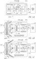
- FIGs. 4A-4C are illustrative representations of CPCN 302 according to some implementations of the present disclosure.
- CPCN 302 is show to include an aggregation function or charging aggregation function (CAF) 402 as part of CDF 312 for aggregating data indicative of network resource usage events of a group or aggregate of UEs. The aggregated data is used for the generation of an aggregate CDR associated with the group or aggregate of UEs.
- CAF 402 is provided separate and apart from CDF 312.
- each one of a plurality of groups of UEs may be associated with a (unique) group ID.
- the group ID may be associated with a list of UE IDs (e.g. IMSIs) corresponding to the UEs in the group.
- UE IDs e.g. IMSIs
- a first plurality of UEs 450 associated with a first group may be associated with a first group ID 452 ("Group ID-X" as indicated) and a second plurality of UEs 460 associated with a second group may be associated with a second group ID 462 ("Group ID-Y" as indicated).
- CTF 310 may be configured to send to the CDF 312 (or the CAF 402) a charging data request which includes charging data indicative of a charging event of the UE.
- the CDF 312 (or the CAF 402) may be configured to, for each one of the first plurality of UEs 450 associated with the first group ID 452, receive from the CTF 310 the charging data request which includes the charging data indicative of the charging event, and store the charging data in association with the group ID 452.
- the CAF 402 may be configured to, in response to identifying a predetermined condition (e.g.
- the CDF 312 may be configured to generate a CDR based on the aggregated data in response to receiving the charging data record generation request.
- CDF 312 may be further configured to send the CDR to CGF 314 via the Ga interface 322, for communication to BD 152 via the Bx interface 324 for processing.
- the above-described process may be performed for the one or more other groups of UEs (e.g. the second plurality of UEs 460 associated with the second group ID 462). Comparing the process of FIG. 4B to that of FIG. 3B , the number of CDRs communicated over Ga interface 322 and Bx interface 324 may be reduced.
- each one of a plurality of aggregates of UEs may be associated with an (unique) aggregation ID.
- the aggregation ID may be associated with a list of UE IDs (e.g. IMSIs) corresponding to the UEs in the aggregate.
- the first plurality of UEs 450 associated with a first aggregate may be associated with a first aggregation ID 454 ("Aggregation ID-X" as indicated) and a second plurality of UEs 460 associated with a second aggregate may be associated with a second aggregation ID 464 ("Aggregation ID-Y" as indicated).
- CTF 310 may be configured to, for each one of first plurality of UEs 450 associated with first aggregation ID 454, send to the CDF 312 (or the CAF 402) a charging data request which includes charging data indicative of a charging event of the UE.
- the CDF 312 (or the CAF 402) may be configured to, for each one of the first plurality of UEs 450 associated with the first aggregation ID 454, receive from the CTF 310 the charging data request which includes the charging data indicative of the charging event and store the charging data in association with first aggregation ID 454.
- the CAF 402 may be configured to, in response to identifying a predetermined condition, aggregate the charging data indicative of the charging events associated with the first aggregation ID 454, and provide to the CDF 312 a charging data record generation request for generating a CDR based on the aggregated data.
- the CDF 312 may be configured to generate a CDR based on the aggregated data in response to receiving the charging data record generation request.
- CDF 312 may be further configured to send the CDR to CGF 314 via the Ga interface 322, for communication to BD 152 via the Bx interface 324 for processing.
- the above-described process may be performed for the one or more other groups of UEs (e.g. the second plurality of UEs 460 associated with the second aggregation ID 464). Comparing the process of FIG. 4B to that of FIG. 3B , the number of CDRs communicated over Ga interface 322 and Bx interface 324 may be reduced.
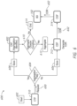
- FIGs. 5A-5B are flowcharts 500 and 520 for describing methods for use in generating data records for communications associated with groups or aggregates of UEs, such as IoT devices, operating in mobile or wireless networks.
- the methods may be embodied in and/or performed by one or more network nodes or functions in a mobile network.
- a network node may be a server, a network element, a network device, or network equipment in the mobile network.
- the methods may be further embodied as one or more computer program products each including a non-transitory computer readable medium and instructions stored in the computer readable medium where the instructions are executable on one or more processors of the one or more network nodes for performing the steps of the method.
- a group or aggregate of UEs may be associated with a (unique) group or aggregation ID; the group or aggregation ID may be associated with a list of UE IDs (e.g. IMSIs) corresponding to the UEs in the group or aggregate.
- a request which includes data indicative of a network resource usage event of a UE may be received (step 502 of FIG. 5A ).
- the network resource usage event may be a data transfer or communications between an application server (AS) and the UE.
- the network resource usage event may be a chargeable event.
- the data indicative of the network resource usage event are stored in association with the group or aggregation ID (step 508 of FIG. 5A ).
- the data may be stored in association with both the group or aggregation ID and the UE ID of the UE.
- the data indicative of the network resource usage event are stored in association with the UE ID associated with the UE (step 508 of FIG. 5A ).
- the UE ID may be an IMSI of the UE.
- step 504 of FIG. 5A may be repeated, where the receiving (i.e. step 504 of FIG. 5A ) and the storing (i.e. step 508 of FIG. 5A ) may be performed for each one of a plurality of UEs associated with the group or aggregation ID, such that a plurality of data indicative of a plurality of network resource usage events of the plurality of UEs are stored in association with the group or aggregation ID.
- the predetermined condition may be a closure condition, for example, an expiration of a time period or a reaching of a volume limit for data transfers involving the plurality of UEs. If the predetermined condition is identified to exist at step 524, the stored data indicative of the plurality of network resource usage events associated with the group or aggregation ID may be aggregated (step 526 of FIG. 5B ). A request for generating a data record based on the aggregated data may be sent to an entity configured to generate a data record based on the aggregated data (step 528 of FIG. 5B ).
- the generated data record may include the group or aggregation ID and stored for subsequent retrieval and/or processing. Note that the method of flowchart 520 of FIG. 5B may directly follow step 508 of FIG. 5A , or may be performed as a process that is separate and independent from the flowchart 520 of FIG. 5B .
- the generated data record may be subsequently processed or used for reporting, analysis, billing, and/or communications management.
- the generated data record may be for use in data analytics in order to study end device and network behaviors, as well as for network planning and UE profiling (e.g. based on machine learning techniques).
- the generated data record may be processed or used for billing the enterprise or customer, where a plurality of such generated data records (e.g. CDRs) over a (predetermined) time period are consolidated into a single billing document.
- the generated data record may include additional data fields and associated data that characterize the group or aggregate processing.
- the data fields and associated data in the generated data record may include the group of aggregation ID, a record type (indicating individual or group/aggregate type), a list of UE IDs (e.g. IMSIs) of (attached) UEs, a total number of established sessions (e.g. PDN sessions), a total number of events generated and/or delivered, a cumulative usage duration, and a cumulative usage volume.
- the one or more network nodes or functions which perform the method of FIG. 5A may include a charging data function (CDF) and/or an aggregation function of the CDF, where the request in step 504 of FIG. 5A is a charging data request which is received from a charging trigger function (CTF).
- the network node or function which performs the method of FIG. 5B may the aggregation function, where the request in step 528 of FIG. 5B is a request for generating a charging data record (CDR).
- the CDR may sent via a charging gateway function (CGF) for receipt at a billing domain entity.
- CGF charging gateway function
- FIG. 6 is a module flow diagram 600 for describing a method for use in generating CDRs for data communications associated with groups or aggregates of UEs, such as IoT devices, operating in mobile or wireless networks.
- the method may be embodied in and/or performed by one or more network nodes or functions in a mobile network.
- a network node may be a server, a network element, a network device, or network equipment in the mobile network.
- the methods may be further embodied as one or more computer program products each including a non-transitory computer readable medium and instructions stored in the computer readable medium where the instructions are executable on one or more processors of the one or more network nodes for performing the steps of the method.
- a group or aggregate of UEs may be associated with a (unique) group or aggregation ID associated with a list of UE IDs (e.g. IMSIs) corresponding to the UEs in the group or aggregate.
- CTF 310 may send a request 650 which includes data indicative of a network resource usage event of a UE.
- the network resource usage event may be a data transfer or communications between an AS and the UE, a chargeable event.
- the chargeable event is stored in association with the UE ID (e.g. IMSI) (step 606 of FIG. 6 ).
- CDF 312 generates a CDR 652 corresponding to the chargeable event and associated with the UE ID.
- CGF 314 may receive the CDR 652 and forward the CDR 652 to the BD 152 for processing (e.g. generating a billing document associated with the UE ID).
- the chargeable event may be stored in association with the group or aggregation ID (and optionally the UE ID) at CAF 402 (step 608 of FIG. 6 ).
- CAF 402 may identify whether an aggregation closure condition has occurred (step 610 of FIG. 6 ).
- the aggregation closure condition may be a data volume limit, or a time or duration limit, as examples. If the aggregation closure condition has not been met at step 610 ("No" at step 610 of FIG. 6 ), then the process ends at an end block 614 without generation of a CDR.
- CAF 402 may aggregate all of the chargeable events associated with the group or aggregation ID (i.e. those that have not yet been previously aggregated or accounted for) (step 612 of FIG. 6 ). Note that, as part of the aggregation rules, an individual IMSI PDN termination or abnormal release will not cause an aggregate CDR to be generated.
- CDF 312 may generate an aggregate CDR 652 corresponding to the aggregated chargeable events associated with the group or aggregation ID.
- CGF 314 may receive the aggregate CDR 652 and forward it to the BD 152 for processing (e.g. generating a billing document associated with the aggregation ID).
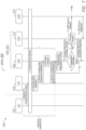
- FIG. 7 is a process flow diagram 700 for describing a method for use in generating CDRs for data communications associated with groups or aggregates of UEs, such as IoT devices, operating in mobile or wireless networks.
- the method described in relation to FIG. 7 may incorporate any of the associated steps or elements described in relation to the previous figures.
- a group or aggregate of UEs may be associated with a (unique) group or aggregation ID; the group or aggregation ID may be associated with a list of UE IDs (e.g. IMSIs) corresponding to the UEs in the group or aggregate.
- UE IDs e.g. IMSIs
- UE 102 and CPCN 302 which includes CTF 310, CDF 312, and CGF 314 are indicated.
- UE 102 may send a message which includes a request for content or service to be delivered via a mobile network (step 1 of FIG. 7 ).
- the mobile network may deliver the requested content or service to the UE 102 (step 2 of FIG. 7 ).
- CTF 310 may generate charging data associated with the content or service delivery (step 3 of FIG. 7 ), and send a charging data request associated with the generated charging data to the CDF 312 or CAF 402 (step 4 of FIG. 7 ).
- CAF 402 may process the request (step 5 of FIG. 7 ), which may include storing the charging data in association with the group or aggregation ID associated with the UE 102.
- CAF 402 may send a message which includes a charging data response (step 6 of FIG. 7 ). Steps 1 through 6 may repeat a number of times for UEs of the same or different group or aggregate.
- CAF 402 may perform a charging data aggregation process.
- CAF 402 may aggregate the multiple, stored chargeable events associated with the same group or aggregation ID (steps 7, 8 and 9 of FIG. 7 ), until the aggregation is complete (taking into account those chargeable events that have not yet been previously aggregated).
- CAF 402 may send or provide to CDF 312 a charging data record generation request which includes the aggregated chargeable event data (step 10 of FIG. 7 ).
- CDF 312 may receive or obtain the request including the aggregated chargeable event data and, in response, process the request for generating an aggregate CDR based on the aggregated chargeable event data (step 11 of FIG. 7 ).
- CDF 312 may send back or provide to CAF 402 a charging data record generation response (step 12 of FIG. 7 ).
- CDF 312 may send a CDR delivery request to CGF 314, for forwarding the generated aggregate CDR to the billing domain "BD" (step 13 of FIG. 7 ).
- CDF 312 may receive a CDR delivery response from CGF 314 (step 14 of FIG. 7 ).
- closure conditions include a data volume limit and a time/duration limit. Additional or alternative closure conditions may be preferred or included, such as a maximum number of NIDD submissions; an MME change; a serving PLMN rate control change for all devices in the aggregation identity; an Aggregation-Id or Group-Id based APN rate control change; a PLMN change; and/or a management intervention.
- FIG. 8 is an illustrative representation of the communication system which includes the mobile network as described in FIG. 1 , incorporating the functions and techniques as described in relation to FIGs. 4A-4C , 5 , 6 and 7 .
- elements of the CPCN may be incorporated in any one or more network functions of the mobile network, including SCEF 120, MME 114, and PGW 118.
- AS 104 may send to BSS/OSS 150 a message which includes a request for subscription or service for a group or aggregate of UEs which are owned, operated, and/or managed by an enterprise of AS 104 (step 0 of FIG. 8 ).
- the subscription or service may be or include a subscription or service for data transfers between an AS (e.g. AS 104) and the group or aggregate of UEs.
- This request may include, implicitly or explicitly, a request for aggregated billing for the group or aggregate of UEs.
- the request may further include, for example, an external ID associated with the request, an application ID associated with an application of AS 104 (e.g. the application involving in the data transfers), and a list of UE IDs (e.g. IMSIs) corresponding to the UEs in the group or aggregate.
- the external ID may be used in the generation of the group or aggregation ID (e.g. the group or aggregation ID may encompass or include some or all of the external ID).
- BSS/OSS 150 may perform a provisioning procedure in mobile network 110 (step 1 in FIG. 8 ). As indicated in FIG. 8 , provisioning may be performed in relation to HSS 112, BD 152, and any one or more of the pertinent network functions including SCEF 120, MME 114, and/or PGW 118. In particular, BSS/OSS 150 may send one or more messages which include a request for provisioning the group or aggregate of UEs to each one of HSS 112, BD 152, and pertinent network functions (e.g. SCEF 120, MME 114, and PGW 118). The request may include, for example, a group or aggregation ID associated with the group or aggregate, and a list of UE IDs (e.g. IMSIs) identifying the UEs of the group or aggregate. For BD 152, the request may further include an application ID associated with the application of AS 104.
- an application ID associated with the application of AS 104.
- UEs 102 of the group or aggregate may operate to register or attach in mobile network 110 (step 2 of FIG. 8 ).
- the UE ID e.g. IMSI
- the pertinent network function(s) e.g. MME 114 and/or SCEF 120.
- HSS 112 may provide to the pertinent network function(s) an aggregation profile (step 3 of FIG. 8 ).
- the aggregation profile may include the group or aggregation ID associated with the group and the list of UE IDs (e.g. IMSIs) corresponding to the UEs in the group or aggregate.
- the aggregation profile may also include one or more aggregation thresholds, which may be for use in the detection of one or more CDR closure conditions (e.g. the aggregation threshold may be a data volume limit, or a time or duration limit, etc.).
- the aggregation threshold may be a data volume limit, or a time or duration limit, etc.
- a plurality of network resource usage events associated with the UEs 102 of the group or aggregate may occur.
- the network resource usage events may be or include data transfers or communications between AS 104 and the UE 102.
- Event data for a given UE of the group or aggregate may be stored in association with the group or aggregation ID.
- the event data may be chargeable event data.
- the event data for the entire group or aggregate may then be aggregated.
- An aggregate CDR may be generated based on the aggregated chargeable event data and delivered to BD 152 (step 4 of FIG. 8 ).
- BD 152 may receive the aggregate CDR for processing (e.g. generating a billing document associated with the aggregation ID). Subsequently, BD 152 may send to AS 104 a message including an aggregated billing based on one or more of such aggregated CDRs (step 5 of FIG. 8 ).
- FIGs. 9A-9E are illustrative representations of architecture implementations options 900 associated with a CPCN (e.g. CPCN 302 of FIGs. 4A-4C , 5A-5B , 6 , 7 , and 8 ).
- CPCN 302 includes CTF 310, CDF 312 having CAF 402, and CGF 314, where CGF 314 and BD 152 communicate via the Bcp interface 324.
- FIG. 9A CPCN 302 includes CTF 310, CDF 312 having CAF 402, and CGF 314, where CGF 314 and BD 152 communicate via the Bcp interface 324.
- CPCN 302 includes CTF 310 and CDF 312 having CAF 402, but CGF 314 is included at a node that is separate and apart from CPCN 302; here, CDF 312 and CGF 314 communicate via the Ga interface 322, and CGF 314 and BD 152 communicate via the Bcp interface 324.
- CPCN 302 includes CTF 310 and CDF 312 having CAF 402, but CGF 314 is included at the BD 152; here, CDF 314 and the CGF 314 at the BD 152 communicate via the Ga interface 322.
- FIG. 9B CPCN 302 includes CTF 310 and CDF 312 having CAF 402, but CGF 314 is included at the BD 152; here, CDF 314 and the CGF 314 at the BD 152 communicate via the Ga interface 322.
- CPCN 302 includes CTF 310, but CDF 312 having CAF 402 is included at a node that is separate and apart from CPCN 302, and CGF 314 is included at the BD 152; here, CTF 310 and CDF 312 communicate via the Rf interface 320, and CDF 314 and CGF 314 at the BD 152 communicate via the Ga interface 322.
- CDF 312 having CAF 402
- CGF 314 is included at the BD 152
- CTF 310 and CDF 312 communicate via the Rf interface 320
- CDF 314 and CGF 314 at the BD 152 communicate via the Ga interface 322.
- CPCN 302 includes CTF 310, but CDF 312 having CAF 402 is included at a node that is separate and apart from CPCN 302, and CGF 314 is included at a node that is separate and apart from CPCN 302; CTF 310 and CDF 312 communicate via the Rf interface 320, CDF 312 and CGF 314 communicate the Ga interface 322, and CGF 314 and BD 152 communicate via the Bcp interface 324.
- a "smart city" IoT service may have 10 million devices across a city with variable usage and event profiles, as follows: (1) Trash Cans - 100,000 - 2 events per day; (2) Parking Meters - 10,000 - 48 events per day; (3) Traffic Lights - 20,000 - 1 event per day; (4) Environmental Monitoring - 24 events per day; and (5) Utility Meters - 1,000,000 - 1 event per day.
- the expected number of CDRs generated per day would be 100 million (i.e. an undesirable, very large number).
- an enterprise may request a service provider to offer a tiered plan based on IoT device usage and use case segment. Billing may therefore be handled on a pertiered plan for a group of IoT devices having similar charging and invoicing policies.
- the number of CDRs may be reduced down to a few 100 CDRs per day, for example, based on unique use cases for LPWA deployments per enterprise.
- FIGs. 10-15 Alternative implementations of the present disclosure are now described in relation to FIGs. 10-15 , for generating a data record for a group data transfer between an AS and a group of UEs.
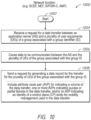
- FIG. 10 is a flowchart 1000 for describing a method for use in generating data records (e.g. CDRs) for data communications associated with groups of UEs, such as IoT devices, operating in mobile or wireless networks.
- the methods may be embodied in and/or performed by one or more network nodes or functions in a mobile network.
- a network function (NF) configured to implement the method of FIG. 10 may be an SCEF (or NEF in 5G) or a S/PGW-C (or AMF in 5G).
- a network node may be a server, a network element, a network device, or network equipment in the mobile network.
- the methods may be further embodied as one or more computer program products each including a non-transitory computer readable medium and instructions stored in the computer readable medium where the instructions are executable on one or more processors of the one or more network nodes for performing the steps of the method.
- a message which includes a request for a data transfer between an AS and a plurality of user equipments (UEs) of a group associated with a group identifier (ID) may be received (step 1004 of FIG. 10 ).
- data may be communicated between the AS and the plurality of UEs of the group associated with the group ID (step 1006 of FIG. 10 ).
- the request for the data transfer is received from the AS and includes the group ID and the data to be delivered, and the data transfer is performed as a series of unicast data deliveries to the UEs of the group associated with the group ID.
- the request for generating a data record associated with the data transfer for the group of UEs may be sent (step 1008 of FIG. 10 ).
- the request for generating a data record may be a charging data record generation request for generating a CDR, where the CDR is associated with and/or includes the group ID.
- the request of FIG. 10 may include an attribute value pair (AVP) indicating a volume of the data transfer for the plurality of UEs of the group associated with the group ID. Additionally, or alternatively, the request may include an AVP indicating an identity of a control plane (CP) entity for mobility management used in the data transfer for the plurality of UEs of the group associated with the group ID. Further additionally or alternatively, the request may include one or AVPs indicating success or partial failures in the data transfer for the plurality of UEs of the group associated with the group ID.
- AVP attribute value pair
- a process flow diagram 1100 of FIG. 11 is shown for describing a method for use in generating data records (e.g. CDRs) for data communications associated with groups of UEs, such as IoT devices, operating in mobile or wireless networks.
- the method of FIG. 11 may be a specific implementation of that previously described in relation to FIG. 10 .
- the method may be performed for data transfers involving non-IP data delivery (NIDD) for IoT devices (e.g. NB loT and/or CAT-M1 devices), and in association with an offline charging system (OFCS) 1150 of the mobile or wireless network and is for non-IP data delivery (NIDD) for IoT devices.
- NIDD non-IP data delivery
- OFCS offline charging system
- AS 104 may send a request for group configuration to SCEF 120 (step 1 of FIG. 11 ).
- the request may include a group ID associated with a group of UEs and a list of UE IDs (e.g. IMSIs) corresponding to the UEs in the group.
- SCEF 120 may perform a group registration for the group, with HSS 112 and/or MME 114.
- SCEF 120 may submit an NIDD authorization request for authorization of the group (step 2 of FIG. 11 ).
- UEs of the group may begin to register/attach to the mobile network.
- a UE-1 may attach to the mobile network, connecting with MME 114 (step 3 of FIG. 11 ).
- MME 114 may send a T6a session establishment request to SCEF 120 (step 4 of FIG. 11 ).
- SCEF 120 may send a charging data request to the OFCS 1150, as it is the first UE of the group to attach (step 5 of FIG. 11 ).
- the request may include the group ID of the group of UEs and a request type indicative of "start”.
- a UE-n may attach to the mobile network, connecting with MME 114 (step 6 of FIG. 11 ).
- MME 114 may send a T6a session establishment request to SCEF 120 (step 7 of FIG. 11 ). Steps 6 and 7 will repeat for additional attachments of UEs in the group.
- one of the UEs 102 may send to MME 114 a non-access stratum (NAS) message which includes MO data for delivery to AS 104 (step 8 of FIG. 11 ).
- MME 114 may send to SCEF 120 a MO data request (ODR) (step 9 of FIG. 11 ).
- the ODR may include a UE ID of the UE and the MO data.
- SCEF 120 may check that a data volume limit for the group (e.g. a group uplink volume) would not be exceeded (step 10 of FIG. 11 ).
- the SCEF 120 may also send a charging data request to the OFCS 1150 (step 11 of FIG. 11 ).
- the charging data request may include the group ID associated with the UE, a request type indicative of "interim" a list of one or more MME IDs associated with the data delivery, and a MO report. Additional UEs may have MO data for delivery in the same or similar manner; for example, a UE-n may send to MME 114 a NAS message which includes MO data for delivery to AS 104 (step 12 of FIG. 11 ). In response, MME 114 may send to SCEF 120 a MO data request or ODR (step 13 of FIG. 11 ).
- AS 104 may send to SCEF 120 a request for MT data delivery to the group of UEs (step 14 of FIG. 11 ).
- the request may be an NIDD submit request which includes the group ID associated with the group and the MT data for delivery.
- SCEF 120 may check that a data volume limit for the group (e.g. a group downlink volume) would not be exceeded (step 15 of FIG. 11 ). If the limit would not be exceeded, SCEF 120 may send the MT data for delivery to the UEs of the group.
- the MT data delivery between SCEF/MME and the UEs may be performed on a UE-by-UE basis.
- SCEF 120 may send to MME 114 an MT data request (TDR) for MT data delivery to one of the UEs in the group (e.g. UE-1) (step 16 of FIG. 11 ).
- the TDR may include a UE ID of the UE-1 and the MT data for delivery.
- MME 114 may send to the UE-1 a NAS message which includes the MT data (step 17 of FIG. 11 ).
- SCEF 120 may keep track and record MT data delivery failures and/or successes (step 18 of FIG. 11 ).
- SCEF 120 may send to MME 114 another MT data request (TDR) for MT data delivery to another one of the UEs in the group (e.g.
- the TDR may include a UE ID of UE-n in the group (e.g. UE-1) and the MT data for delivery.
- MME 114 may send to the UE-n a NAS message which includes the MT data (step 20 of FIG. 11 ). Steps 19 and 20 will repeat for additional deliveries to UEs in the group.
- SCEF 120 may send a charging data request to the OFCS 1150 (step 21 of FIG. 11 ).
- the charging data request may include the group ID associated with the UE, a request type indicative of "interim," and a MO report of success(es) and/or failure(s).
- a CDR may be generated for the data delivery to the group of UEs in response to the charging data request.
- UEs of the group may begin to detach from the mobile network.
- a UE-1 may detach from the mobile network, disconnecting with MME 114 (step 22 of FIG. 11 ).
- MME 114 may send a T6a session termination request to SCEF 120 (step 23 of FIG. 11 ).
- SCEF 120 may send a charging data request to the OFCS 1150, indicating the detachment (step 24 of FIG. 11 ).
- the request may include the group ID of the group of UEs and a request type indicative of "start". Note that SCEF 120 may check whether the detachment is from the last one of the UEs in the group (step 25 of FIG. 11 ).
- SCEF 120 may send a charging data request to the OFCS 1150, indicating the detachment (step 26 of FIG. 11 ), which may include the group ID of the group of UEs and a request type indicative of "stop". Similarly, may detach from the mobile network, disconnecting with MME 114 (step 27 of FIG. 11 ). In response, MME 114 may send a T6a session termination request to SCEF 120 (step 28 of FIG. 11 ). Steps 27 and 28 will repeat for additional detachments of UEs in the group.
- a CTF requests a CDF to store event related charging data for CDR generation purposes.
- the charging data request in the technique of FIG. 11 may include one or more additional AVPs related to group processing.
- FIG. 13 a table 1300 for listing a service-information AVP of a charging data request is shown.
- a first column 1302 indicates an information element (IE)
- a second column 1304 indicates a category of the IE
- a third column 1306 indicates a description of the IE.
- the service-information AVP of FIG. 13 includes a group identifier (ID) and a group APN rate control which may be enforced in the SCEF for the record.
- ID group identifier
- APN rate control which may be enforced in the SCEF for the record.
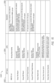
- FIG. 14 what is shown is a table 1400 for listing a control plane data transfer (CPDT) AVP of the service-information AVP of FIG. 13 (i.e. the last IE in table 1300 of FIG. 13 ).
- CPDT control plane data transfer
- a first column 1402 indicates the CPDT AVP
- a second column 1404 indicates a category
- a third column 1406 indicates a description of the CPDT AVP.
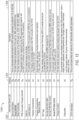
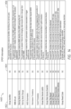
- FIG. 15 a table 1500 for defining or describing CPDT AVPs for use with groups of UEs and associated with FIG. 14 is shown.
- a first column 1502 indicates an AVP name
- a second column 1504 indicates the AVP
- a third column 1506 indicates a description of the AVP.
- New, additional AVPs as indicated in FIGs. 14-15 include a group identifier (ID); an MME ID list; a group data volume for uplink data transfers; a group data volume for downlink data transfers; a group T6a report; a group MO report; a group MT report-success; a group MT report-partial delivery; and a group result code.
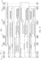
- a process flow diagram 1200 of FIG. 12 is shown for describing a method for use in generating CDRs for data communications associated with groups of UEs, such as IoT devices, operating in mobile or wireless networks.
- the group of UEs may be associated with a (unique) group or aggregation ID; the group ID may be associated with a list of UE IDs (e.g. IMSIs) corresponding to the UEs in the group.
- the method of FIG. 12 may be a specific implementation of that previously described in relation to FIG. 10 .
- the method may be performed for data transfers involving IP data delivery for IoT devices (e.g. CAT-M1 devices), and in association with an online charging system (OCS) 1250 of the mobile or wireless network.
- IoT devices e.g. CAT-M1 devices
- OCS online charging system
- a first or initial one of the UEs in the group may operate to register or attach in mobile network 110 (step 1 of FIG. 12 ).
- the UE ID e.g. IMSI
- MME 114 may send to S/PGW 118 a message which includes a create session request which includes the UE ID (step 2 of FIG. 12 ).
- S/PGW 118 may establish a Gx session with PCRF 116 (step 3 of FIG. 12 ).
- PCRF 116 may send to S/PGW 118 a message which includes a credit check answer (CCA) having one or more PCC rules for installation at the S/PGW 118 (step 4 of FIG. 12 ).
- the one or more PCC rules may be used for policy enforcement at S/PGW 118 for the individual UE.
- S/PGW 118 may determine and/or associate the group ID of the UE (step 5 of FIG. 12 ).
- S/PGW 118 may send to the OCS 1250 a message which includes a credit check request (CCR) (step 6 of FIG. 12 ). This request may include the UE ID and the determined group ID.
- OCS 1250 may send back to S/PGW 118 a message which includes a credit check answer (CCA) (step 7 of FIG. 12 ).
- the CCA may provide a credit authorization for the group over the Gy interface.
- a subsequent one of the UEs in the group may operate to register or attach in mobile network 110 (step 8 of FIG. 12 ).
- the UE ID e.g. IMSI
- MME 114 may send to S/PGW 118 a message which includes a create session request which includes the UE ID (step 9a of FIG. 12 ).
- S/PGW 118 may determine and/or associate the group ID of the UE (step 9b of FIG. 12 ).
- Steps 8-9 may be repeated for each of one or more additional UEs in the group.
- one of the UEs 102 may send UL IP data to eNB 106 (step 10 of FIG. 12 ) which forwards the data to S/PGW 118 (step 11 of FIG. 12 ).
- S/PGW 118 may check that an UL data volume limit for the group (e.g. a group UL volume) would not be exceeded by the UL data delivery (step 12 of FIG. 12 ).
- S/PGW 118 may send to the OCS 1250 a message which includes a CCR (step 12 of FIG. 12 ). This request may include the group ID, the UL data volume, and the MO report (step 13 of FIG. 12 ).
- Additional UEs may have UL data for delivery in the same or similar manner; for example, a UE-n may send via eNB 106 UL data for delivery (step 14 of FIG. 12 ) and these data are forwarded to S/PGW 118 (step 15 of FIG. 12 ).
- AS 104 may send a request for IP data delivery to UEs 102 in the group (step 16 of FIG. 12 ).
- the request may include one or more UE IDs (e.g. one or more destination IP addresses) and the DL data for delivery.
- S/PGW 118 may determine or associate a group ID with the UE IDs (step 17 of FIG. 12 ).
- S/PGW 118 may check that an DL data volume limit for the group (e.g. a group DL volume) associated with the group ID would not be exceeded by the DL data delivery (step 18 of FIG. 12 ).
- S/PGW 118 may send to the OCS 1250 a message which includes a CCR (step 19 of FIG. 12 ).
- This request may include the group ID, the DL data volume, and the MT report.
- S/PGW 118 may send the DL data to eNB 106 (step 20 of FIG. 12 ) for delivery to the UEs 102 in the mobile network (step 21 of FIG. 12 ). Additional DL IP data deliveries to UEs 102 may occur in the same or similar manner; for example, AS 104 may send a request for IP data delivery to UEs 102 in the group (step 22 of FIG. 12 ), where steps 17-19 are repeated (step 23 of FIG. 12 ), and where S/PGW 118 sends the DL data to eNB 106 (step 24 of FIG. 12 ) for delivery to the UEs 102 in the mobile network (step 25 of FIG. 12 ).
- one of the UEs in the group may operate detach from the mobile network, disconnecting from MME 114 (step 26 of FIG. 12 ).
- MME 114 may send to S/PGW 118 a message which includes a delete session request which includes the UE ID (step 27 of FIG. 12 ).
- S/PGW 118 may determine if all members of the group have detached, or whether a time interval has expired (step 28 of FIG. 12 ).
- S/PGW 118 may send to the OCS 1250 a message which includes a CCR (step 19 of FIG. 12 ).
- This request may include the group ID, the total UP/DL bandwidth, and a list of inactive members of the group (e.g. the UE IDs or IP addresses thereof).
- UEs user equipments
- IoT Internet of Things
- UEs user equipments
- IoT Internet of Things
- a request which includes data indicative of a network resource usage event of the UE is received and the data are stored in association with the group or aggregation ID.
- the data indicative of the network resource usage events associated with the group or aggregation ID are aggregated.
- a request for generating a data record based on the aggregated data is then sent to a data function for generating a data record.
- the generated data record may be stored for subsequent retrieval, for reporting, analysis, billing, and/or communications management.
- the predetermined condition may be or include, as examples, an expiration of a time period, or a detection of a volume limit for data transfers involving the plurality of UEs.
- the technique may be performed by one or more network nodes or functions of a mobile network.
- the one or more network nodes or functions comprise a charging data function (CDF) which includes an aggregation function, where the request including the data indicative of the network resource usage event is a charging data request from a charging trigger function (CTF), and the request for generating a data record is a request for generating a charging data record (CDR).
- CDF charging data function
- CTF charging trigger function
- CDR charging data record
- the CDR may sent via a charging gateway function (CGF) for receipt at a billing domain entity.
- CGF charging gateway function
- a system of the present disclosure may include one or more network nodes of a control plane (CP) entity for data transfer charging (e.g. a control plane data transfer charging node or "CPCN").
- the one or more network nodes may have a CTF and a CDF which may include an aggregation function.
- the CTF may be configured to, for each one of a plurality of UEs associated with a group or aggregation ID, send to the CDF (or the aggregation function thereof) a charging data request which includes charging data indicative of a charging event of the UE.
- the CDF (or the aggregation function thereof) may be configured to, for each one of the plurality of UEs associated with the group or aggregation ID, receive from the CTF the request which includes the charging data indicative of the network resource usage event and store the charging data in association with the group or aggregation ID.
- the aggregation function may be configured to, in response to identifying a predetermined condition, aggregate the charging data indicative of the charging events associated with the group or aggregation ID, and provide to the CDF a charging data record generation request for generating a CDR based on the aggregated data.
- the CDR may sent via a CGF for receipt at a billing domain entity.
- a request for a data transfer between an AS and a plurality of UEs of a group associated with a group ID is received.
- data are communicated between the AS and the plurality of UEs of the group associated with the group ID.
- a request for generating a data record for the data transfer for the plurality of UEs of the group associated with the group ID is sent to a system for generating data records.
- the request for generating the data record may include, for example, an attribute value pair (AVP) indicating a volume of the data transfer for the plurality of UEs of the group, one or more AVPs indicating success or partial failures in the data transfer for the plurality of UEs of the group, and/or an AVP indicating an identity of a CP entity for mobility management used in the data transfer for the plurality of UEs of the group.
- AVP attribute value pair
- the request for generating the data record may be a charging data request for generating a CDR, where the CDR is sent via a CGF for receipt at a billing domain entity.
- first could be termed a second request
- second request could be termed a first request, without changing the meaning of the description, so long as all occurrences of the "first request” are renamed consistently and all occurrences of the "second request” are renamed consistently.
- the first request and the second request are both requests, but they are not the same request.
- the term “if' may be construed to mean “when” or “upon” or “in response to determining” or “in accordance with a determination” or “in response to detecting,” that a stated condition precedent is true, depending on the context.
- the phrase “if it is determined [that a stated condition precedent is true]” or “if [a stated condition precedent is true]” or “when [a stated condition precedent is true]” may be construed to mean “upon determining” or “in response to determining” or “in accordance with a determination” or “upon detecting” or “in response to detecting” that the stated condition precedent is true, depending on the context.
Landscapes
- Engineering & Computer Science (AREA)
- Computer Networks & Wireless Communication (AREA)
- Signal Processing (AREA)
- Physics & Mathematics (AREA)
- Probability & Statistics with Applications (AREA)
- Business, Economics & Management (AREA)
- Accounting & Taxation (AREA)
- Databases & Information Systems (AREA)
- Mobile Radio Communication Systems (AREA)
- Meter Arrangements (AREA)
Description
- The present disclosure relates generally to a method, computer program and apparatus for use in generating data records for data communications involving groups or aggregates of mobile devices, such as Internet of Things (IoT) devices, operative in mobile or wireless networks.
- A need has been identified for a more process-efficient generation of data records for data communications associated with mobile devices, such as Internet of Things (IoT) devices, operating in mobile or wireless networks.
- In
US2015373205 a network element collects, within a time window, charging information of a plurality of user equipments belonging to a same group, aggregates the charging information to obtain a charging aggregation result, and sends the charging aggregation result to a corresponding device in said system. The charging system receives a plurality of pieces of aggregated charging information and time windows sent by a network element in the system, wherein each piece of charging information respectively corresponds to one of the time windows, and aggregates the plurality of pieces of aggregated charging information based on the time windows and the group(s) and/or sub-group(s) to which the user equipments belong, to generate charging data record(s), wherein the time windows and the user equipments correspond to the plurality of pieces of aggregated charging information. - So that the present disclosure can be understood by those of ordinary skill in the art, a more detailed description may be had by reference to aspects of some illustrative implementations, some of which are shown in the accompanying drawings.
-
FIG. 1 is an illustrative representation of a communication system which includes a mobile network for providing wireless communications for a plurality of user equipments (UEs), such as Internet of Things (IoT) devices; -
FIG. 2 is an illustrative representation of a reference architecture of a service and capability exposure function (SCEF) in the mobile network ofFIG. 1 ; -
FIGs. 3A-3B are illustrative representations of a control plane data transfer charging node (CPCN) of the mobile network ofFIG. 1 , where the CPCN has a plurality of network functions including a charging trigger function (CTF), a charging data function (CDF) for generating a charging data record (CDR), and a charging gateway function (CGF); -
FIGs. 4A-4C are illustrative representations of a CPCN according to some implementations of the present disclosure, where the CDF includes an aggregation function or charging aggregation function (CAF) for aggregating data indicative of network resource usage events of groups or aggregates of UEs; -
FIGs. 5A-5B are flowcharts for describing methods for use in generating data records for communications associated with groups or aggregates of UEs, such as loT devices, operating in mobile or wireless networks; -
FIG. 6 is a module flow diagram for describing a method for use in generating CDRs for data communications associated with groups or aggregates of UEs, such as IoT devices, operating in mobile or wireless networks; -
FIG. 7 is a process flow diagram for describing a method for use in generating CDRs for data communications associated with groups or aggregates of UEs, such as IoT devices, operating in mobile or wireless networks; -
FIG. 8 is an illustrative representation of the communication system which includes the mobile network as described inFIG. 1 , incorporating the functions and techniques as described in relation toFIGs. 4A-4C ,5A-5B ,6 and7 ; -
FIGs. 9A-9E are illustrative representations of architecture implementations options for a CPCN having a CTF, a CDF, a CAF, and a CGF; -
FIG. 10 is a flowchart for describing a method for use in generating data records for data communications associated with groups or aggregates of UEs, such as IoT devices, operating in mobile or wireless networks; -
FIG. 11 is a process flow diagram for describing a method for use in generating CDRs for data communications associated with groups or aggregates of UEs, such as IoT devices, operating in mobile or wireless networks, for use with an offline charging system (OFCS); -
FIG. 12 is a process flow diagram for describing a method for use in generating CDRs for data communications associated with groups or aggregates of UEs, such as IoT devices, operating in mobile or wireless networks, for use with an online charging system (OCS); -
FIG. 13 is a table including a service-information attribute-value pair (AVP) of a charging data request, for use with the OFCS in the method ofFIG. 11 ; -
FIG. 14 is a table including a control plane data transfer (CPDT) AVP of the service-information AVP ofFIG. 13 , for use with the OFCS in the method ofFIG. 11 ; and -
FIG. 15 is a table which defines CPDT AVPs for use with groups of UEs and associated withFIG. 14 , for use with the OFCS in the method ofFIG. 11 . - In accordance with common practice the various features illustrated in the drawings may not be drawn to scale. Accordingly, the dimensions of the various features may be arbitrarily expanded or reduced for clarity. In addition, some of the drawings may not depict all of the components of a given system, method or device. Finally, like reference numerals may be used to denote like features throughout the specification and figures.
- Numerous details are described in order to provide a thorough understanding of the example implementations shown in the drawings. However, the drawings merely show some example aspects of the present disclosure and are therefore not to be considered limiting. Those of ordinary skill in the art will appreciate that other effective aspects and/or variants do not include all of the specific details described herein. Moreover, well-known systems, methods, components, devices and circuits have not been described in exhaustive detail so as not to obscure more pertinent aspects of the example implementations described herein.
- Methods, apparatus, and systems for use in the process-efficient generation of data records for data communications involving groups or aggregates of user equipment (UEs), such as Internet of Things (IoT) devices, are described herein.
- In one illustrative example, for each one of a plurality of UEs associated with a group or aggregation identifier (ID), a request which includes data indicative of a network resource usage event of the UE is received and the data are stored in association with the group or aggregation ID. In response to identifying a predetermined condition, the data indicative of the network resource usage events associated with the group or aggregation ID are aggregated. A request for generating a data record based on the aggregated data is then sent to a data function for generating a data record. The generated data record may be stored for subsequent retrieval, for reporting, analysis, billing, and/or communications management. The predetermined condition may be or include, as examples, an expiration of a time period, or a detection of a volume limit for data transfers involving the plurality of UEs.
- The technique may be performed by one or more network nodes or functions of a mobile network. For example, the one or more network nodes or functions comprise a charging data function (CDF) which includes an aggregation function, where the request including the data indicative of the network resource usage event is a charging data request from a charging trigger function (CTF), and the request for generating a data record is a request for generating a charging data record (CDR). The CDR may sent via a charging gateway function (CGF) for receipt at a billing domain entity.
- A system of the present disclosure may include one or more network nodes of a control plane (CP) entity for data transfer charging (e.g. a control plane data transfer charging node or "CPCN"). The one or more network nodes may have a CTF and a CDF which may include an aggregation function. The CTF may be configured to, for each one of a plurality of UEs associated with a group or aggregation ID, send to the CDF (or the aggregation function thereof) a charging data request which includes charging data indicative of a charging event of the UE. The CDF (or the aggregation function thereof) may be configured to, for each one of the plurality of UEs associated with the group or aggregation ID, receive from the CTF the request which includes the charging data indicative of the network resource usage event and store the charging data in association with the group or aggregation ID. The aggregation function may be configured to, in response to identifying a predetermined condition, aggregate the charging data indicative of the charging events associated with the group or aggregation ID, and provide to the CDF a charging data record generation request for generating a CDR based on the aggregated data. The CDR may sent via a CGF for receipt at a billing domain entity.
- In at least some other implementations, a request for a data transfer between an AS and a plurality of UEs of a group associated with a group ID is received. In response to the request for the data transfer, data are communicated between the AS and the plurality of UEs of the group associated with the group ID. A request for generating a data record for the data transfer for the plurality of UEs of the group associated with the group ID is sent to a system for generating data records. The request for generating the data record may include, for example, an attribute value pair (AVP) indicating a volume of the data transfer for the plurality of UEs of the group, one or more AVPs indicating success or partial failures in the data transfer for the plurality of UEs of the group, and/or an AVP indicating an identity of a CP entity for mobility management used in the data transfer for the plurality of UEs of the group. The request for generating the data record may be a charging data request for generating a CDR, where the CDR is sent via a CGF for receipt at a billing domain entity.
- More detailed, additional, and alternative techniques and implementations are described further below.
- Electronic data records may be generated for a variety of different purposes, such as for documenting communications associated with mobile devices operating in mobile (wireless) networks. Such data records may be stored for subsequent retrieval for reporting, analysis, billing, or communications management. A particular need for a more process-efficient generation of data records for data communications associated with Internet of Things (IoT) devices operating in mobile networks has been identified.
- With reference to
FIG. 1 , an illustrative representation of acommunication system 100 which includes amobile network 110 is shown.Mobile network 110 ofFIG. 1 is configured as a Fourth generation (4G), Long Term Evolution (LTE), Evolved Packet Core (EPC) based mobile network.Mobile network 110 includes a plurality of network nodes or entities, such as a home subscriber server (HSS) 112, a mobility management entity (MME) 114, a policy and charging rules function (PCRF) 116, a serving/packet data network (S/P) gateway (S/P GW) 118, and a service and capability exposure function (SCEF) 120.Mobile network 110 may further include a business support system (BSS) / operations support system (OSS) 150 and a billing domain (BD)entity 152. A plurality of user equipment (UEs) 102 may accessmobile network 110 via one or more base stations, such as an eNodeB (eNB) 106, for communication. -
SCEF 120 is one type of network node configured for exposure of services and capabilities of themobile network 110, and for interfacing with application servers (e.g. an application server or AS 104).SCEF 120 may interface with AS 104 (e.g. with use of a REST API) for communicating data between theAS 104 andUEs 102. Aconnectivity management platform 130 may also be used in association withSCEF 120. Further,SCEF 120 may interface with one or more MME entities (e.g. MME 114) for non-IP data delivery (NIDD), and one or more S/P GW entities (e.g. S/P GW 118) and one or more PCRFs entities (e.g. PCRF 116) for IP data delivery. A first mobile network route for data communication makes use of aT6a interface 192 for NIDD, and a second mobile network route for data communication makes use of aSGi interface 194 which terminates atSCEF 120 for IP data delivery. In preferred implementations,SCEF 120 is an enhanced SCEF (eSCEF) described in 3GPP TS 23.682 specifications. -
UEs 102 may include lightweight machine-to-machine (LWM2M) devices, such as a UE 102a which is a CAT-M1 device and a UE 102b which is a Narrowband (NB) IoT device. Note thatSCEF 120 may include aLWM2M server 180 configured for use with UEs that are LWM2M clients, as well as other applicable functionalities such as Constrained Application Protocol (CoAP) and Datagram Transport Layer Security (DTLS) functions. Basic processing associated with CAT-M1 devices (e.g. UE 102a) and NB-IoT devices (e.g. UE 102b) are now briefly discussed. UE 102a, which is a CAT-M1 device, is configured to support IP data delivery for wideband (WB) data communication, as well as NIDD for narrowband (NB) data communication.SCEF 120 may become aware when UE 102a connects tomobile network 110 via the PCRF / SCEF interface. At this time,SCEF 120 may create a context for UE 102a which includes its IP address as an identity. For mobile-terminated (MT) data to be delivered to UE 102a, given the creation of the UE context,SCEF 120 may send MT data from AS 104 to UE 102a via S/P-GW 118 over theSGi interface 194. Note that AS 102 may not even be aware how MT data is delivered to UE 102a (i.e. whether over theSGi interface 194 for IP data delivery or theT6a interface 192 for NIDD). - NB IoT is a Low Power Wide Area Network (LPWAN) radio technology developed to enable a wide range of devices and services to be utilized in cellular bands. An NB IoT device, such as UE 102b, is a constrained device that is not configured to support IP data delivery; rather, NB loT devices are configured to support NIDD for NB data communication. For NIDD, AS 104 may initiate a procedure that triggers an NIDD configuration procedure between
SCEF 120 andHSS 112. As a result of the procedure, an HSS record of UE 102b indicates that 120 will handle the connection to the access point name (APN). This information may be sent toMME 114 as part of the attachment procedure.MME 114 may initiate a T6a session establishment toSCEF 120. MT data for delivery to UE 102b may be sent over theT6a interface 192 toMME 114 based on the UE context (and/or session record) created when the T6a session establishment is performed. -
FIG. 2 is a basic illustrative representation ofSCEF reference architecture 200 ofSCEF 120. The basis forSCEF reference architecture 200 ofFIG. 2 may be found in 3rd Generation Partnership Project (3GPP) Technical Specification (TS) 23.682 (i.e. 3GPP TS 23.682). InSCEF reference architecture 200,SCEF 120 is shown to include one or more application programming interfaces (APIs) 206 (such as an API 208) for one or more applications 202 (such as an application 204) of the application servers. The one ormore applications 202 may include third-party applications for third-part application servers. A plurality of3GPP interfaces 210 are defined betweenSCEF 120 and a plurality ofother network entities 212 in the mobile network. 3GPP interfaces relevant to techniques of the present disclosure include theT6a interface 192 for interfacing withMME 114, and Nt andTx interfaces 196 and 198 (FIGs. 1 and2 ) for interfacing withPCRF 116. - Again,
SCEF 120 is one type of network node configured for exposure of services and capabilities ofmobile network 110, as well as for interfacing with application servers for communication of data via themobile network 110. Another type of network node configured for exposure of services and capabilities of a mobile network is a network exposure function (NEF) node of a 5G mobile network (not shown inFIGs. 1 and2 ). Here, in some implementations, the NEF may interface with one or more access and mobility management (AMF) entities for NIDD, and/or one or more user plane functions (UPF) entities and one or more policy control function (PCF) entities for IP data delivery. - Referring back to
FIG. 1 , note that electronic data records may be generated for network resource usage events (e.g. data communications or transfers) of theUEs 102 inmobile network 110. The data records may be stored for subsequent retrieval for reporting, analysis, billing, or communications management. For example, billing forcommunications involving UEs 102 typically involves the generation of charging data records (CDRs) for chargeable events. Any chargeable event per subscriber in the form of a CDR can be monetized by the operator ofmobile network 110. - To further explain, an offline charging system (OFCS) of the mobile network is shown in relation to
FIGs. 3A-3B , which includes a control plane data transfer charging node (CPCN) 302 of the mobile network ofFIG. 1 .CPCN 302 ofFIG. 3A is detailed in 3GPP documentation, such as TS 32.240 and TS 32.299. InFIG. 3A ,CPCN 302 has a plurality of network functions which include a charging trigger function (CTF) 310, a charging data function (CDF) 312, and a charging gateway function (CGF) 314.CTF 310 may interface withCDF 312 via anRf interface 320, andCDF 312 may interface withCGF 314 via a Ga interface.CGF 314 may interface with a billing domain (BD)entity 152 via aBx interface 324. In general,CTF 310 is configured to generate and send a charging data request toCDF 312 in response to detecting a network resource usage event (e.g. a charging event) of a UE.CDF 312 is configured to generate a charging data record (CDR) in response to receiving a charging data request fromCTF 310.CDF 312 is further configured to send the CDR viaCGF 314 for receipt and processing at theBD 152. - The OFCS of the mobile network may process events from UEs that are IoT devices. Note that LPWAN is becoming the preferable deployment choice for IoT applications, including smart city, smart industries, and smart agriculture use cases. Such "smart IoT devices" have to reliably communicate with applications in small bursts of data associated with different traffic models. These traffic models are varied based on the frequency of data transferred (e.g. from one to few times a day, to a few times in a month or a year). A smart IoT device may have many brief data sessions, each of which is an individually chargeable event. Each event would trigger the generation of a CDR, resulting in a large number of CDRs. The large number of CDRs for such small data transfers may overwhelm operator billing systems, adding significant processing costs to generate invoices for billing. The additional cost to process small and infrequent CDRs for data sessions would seem to negatively impact an attempt to adopt the new technology at a low cost. This becomes even more important for non-IP data delivery (NIDD) using the SCEF, as the traffic pattern for NIDD will be small and infrequent.
- With reference to
FIG. 3B , each one of a large number ofUEs 350 may use a network resource in the mobile network. For example, an IoT device may be involved in a data transfer involving a small amount of data. Each network resource usage by a UE may cause a record chargingdata request 320 to be generated and sent fromCTF 310 toCDF 312. In response,CDF 312 may generate and send aCDR 322 corresponding to the record chargingdata request 320.CDR 322 may be received atCGF 314, which forwards acorresponding CDR 324 toBD 152 for processing. As is apparent, a large number of CDRs from a large number ofUEs 350 may overwhelm operator billing systems, adding significant processing costs to generate invoices and billing. - Thus, a more process-efficient generation of data records for data communications associated with IoT devices operating in mobile or wireless networks is needed.
- According to at least some implementations of the present disclosure, what are described are techniques for lowering the number of generated data records for IoT devices, using an aggregation mechanism to aggregate event data from the IoT devices for the generation of a single aggregate data record (e.g. an aggregate CDR) based on the aggregated event data.
- In one implementation, what is provided is aggregated data record generation using a group identifier (ID). Here, a number of UEs with similar characteristics are grouped together and assigned to a group ID. The group ID along with its associated UE members may be provisioned at the MME, SCEF, BD, and/or the AS. The MME and SCEF may trigger the opening of a CDR when the first UE member of the group attaches to the network. The group ID may be stored in the CDR. As additional UE members attach to the network, a UE ID of the UE may be added to the CDR. The SCEF and MME may keep track of group usage (e.g. data volume and/or time usage), group PLMN rate control, and group APN rate control, and close the CDR when a condition is met.
- In another implementation, what is provided is aggregated data record generation using an aggregation ID. Here, the unique identifier may be assigned to a UE profile of a UE that belongs to a common service plan. The aggregation ID may be provisioned as part of the HSS profile or on one or more network elements, such as the SCEF or MME. Here, the aggregation ID may be derived from the PCF for user plane delivery via the PGW.
- These aggregation identifiers may be generated by a network element, such as the SCEF, and encompass or otherwise be based on an external identifier received from the AS or its application. The aggregation identifiers may use or otherwise be based on group identifiers per the groups provisioned at the HSS, SCEF, and/or AS. Activation may be made via the group configuration REST API (i.e. from the AS to the SCEF); diameter T6a group NIDD Authorization command (i.e. from the SCEF to the HSS) per 3GPP TS 23.682.
- The aggregation identifiers may be shared with the network elements, such as the CPCN, so that its included as part of the CTF accounting metrics collection and forwarding sent to the CDF for CDR generation. This will allow correlation of the CDRs in the CAF to generate an aggregate CDR for multiple IMSIs and events before it reaches the billing domain.
- In some implementations, an aggregate CDR may be generated in response to identifying any one or more of one or more closure conditions. The aggregation may be a time-based aggregation, a usage-based aggregation, an application-aware based aggregated, an application triggered aggregation, and/or a monitored event triggered aggregation. An aggregate CDR may include traditional CDR data fields per TS 32.253, and further include one or more additional fields including CDR type (individual or aggregate); total number of SCEF/PDN session establishments; total number of events generated and delivered; cumulative usage duration; cumulative usage volume; and list of source IMSIs that attached to the network at CDR closing and target destination networks.
-
FIGs. 4A-4C are illustrative representations ofCPCN 302 according to some implementations of the present disclosure. InFIG. 4A ,CPCN 302 is show to include an aggregation function or charging aggregation function (CAF) 402 as part ofCDF 312 for aggregating data indicative of network resource usage events of a group or aggregate of UEs. The aggregated data is used for the generation of an aggregate CDR associated with the group or aggregate of UEs. In some implementations,CAF 402 is provided separate and apart fromCDF 312. - In some implementations with reference to
FIG. 4B , each one of a plurality of groups of UEs may be associated with a (unique) group ID. The group ID may be associated with a list of UE IDs (e.g. IMSIs) corresponding to the UEs in the group. For example, a first plurality ofUEs 450 associated with a first group may be associated with a first group ID 452 ("Group ID-X" as indicated) and a second plurality ofUEs 460 associated with a second group may be associated with a second group ID 462 ("Group ID-Y" as indicated). For each one of the first plurality ofUEs 450 associated with thefirst group ID 452,CTF 310 may be configured to send to the CDF 312 (or the CAF 402) a charging data request which includes charging data indicative of a charging event of the UE. The CDF 312 (or the CAF 402) may be configured to, for each one of the first plurality ofUEs 450 associated with thefirst group ID 452, receive from theCTF 310 the charging data request which includes the charging data indicative of the charging event, and store the charging data in association with thegroup ID 452. TheCAF 402 may be configured to, in response to identifying a predetermined condition (e.g. expiration of a time period or reaching a volume limit), aggregate the charging data indicative of the charging events associated with thefirst group ID 452 and provide to the CDF 312 a charging data record generation request for generating a CDR based on the aggregated data. TheCDF 312 may be configured to generate a CDR based on the aggregated data in response to receiving the charging data record generation request.CDF 312 may be further configured to send the CDR toCGF 314 via theGa interface 322, for communication toBD 152 via theBx interface 324 for processing. The above-described process may be performed for the one or more other groups of UEs (e.g. the second plurality ofUEs 460 associated with the second group ID 462). Comparing the process ofFIG. 4B to that ofFIG. 3B , the number of CDRs communicated overGa interface 322 andBx interface 324 may be reduced. - In other implementations with reference to
FIG. 4C , each one of a plurality of aggregates of UEs may be associated with an (unique) aggregation ID. The aggregation ID may be associated with a list of UE IDs (e.g. IMSIs) corresponding to the UEs in the aggregate. For example, the first plurality ofUEs 450 associated with a first aggregate may be associated with a first aggregation ID 454 ("Aggregation ID-X" as indicated) and a second plurality ofUEs 460 associated with a second aggregate may be associated with a second aggregation ID 464 ("Aggregation ID-Y" as indicated). Here,CTF 310 may be configured to, for each one of first plurality ofUEs 450 associated withfirst aggregation ID 454, send to the CDF 312 (or the CAF 402) a charging data request which includes charging data indicative of a charging event of the UE. The CDF 312 (or the CAF 402) may be configured to, for each one of the first plurality ofUEs 450 associated with thefirst aggregation ID 454, receive from theCTF 310 the charging data request which includes the charging data indicative of the charging event and store the charging data in association withfirst aggregation ID 454. TheCAF 402 may be configured to, in response to identifying a predetermined condition, aggregate the charging data indicative of the charging events associated with thefirst aggregation ID 454, and provide to the CDF 312 a charging data record generation request for generating a CDR based on the aggregated data. TheCDF 312 may be configured to generate a CDR based on the aggregated data in response to receiving the charging data record generation request.CDF 312 may be further configured to send the CDR toCGF 314 via theGa interface 322, for communication toBD 152 via theBx interface 324 for processing. The above-described process may be performed for the one or more other groups of UEs (e.g. the second plurality ofUEs 460 associated with the second aggregation ID 464). Comparing the process ofFIG. 4B to that ofFIG. 3B , the number of CDRs communicated overGa interface 322 andBx interface 324 may be reduced. -
FIGs. 5A-5B areflowcharts - In
FIG. 5A , a group or aggregate of UEs may be associated with a (unique) group or aggregation ID; the group or aggregation ID may be associated with a list of UE IDs (e.g. IMSIs) corresponding to the UEs in the group or aggregate. Beginning at astart block 502 of theflowchart 500 ofFIG. 5A , a request which includes data indicative of a network resource usage event of a UE may be received (step 502 ofFIG. 5A ). The network resource usage event may be a data transfer or communications between an application server (AS) and the UE. The network resource usage event may be a chargeable event. If the UE is associated with a group or aggregation ID ("Yes" as identified instep 506 ofFIG. 5A ), the data indicative of the network resource usage event are stored in association with the group or aggregation ID (step 508 ofFIG. 5A ). In some implementations ofstep 508, the data may be stored in association with both the group or aggregation ID and the UE ID of the UE. If the UE is not associated with a group or aggregation ID ("No" as identified instep 506 ofFIG. 5A ), the data indicative of the network resource usage event are stored in association with the UE ID associated with the UE (step 508 ofFIG. 5A ). In some implementations, the UE ID may be an IMSI of the UE. The method ofFIG. 5A may be repeated, where the receiving (i.e.step 504 ofFIG. 5A ) and the storing (i.e.step 508 ofFIG. 5A ) may be performed for each one of a plurality of UEs associated with the group or aggregation ID, such that a plurality of data indicative of a plurality of network resource usage events of the plurality of UEs are stored in association with the group or aggregation ID. - Continuing at a
start block 522 of theflowchart 520 ofFIG. 5B , it may be identified whether a predetermined condition exists (step 524 ofFIG. 5B ). The predetermined condition may be a closure condition, for example, an expiration of a time period or a reaching of a volume limit for data transfers involving the plurality of UEs. If the predetermined condition is identified to exist atstep 524, the stored data indicative of the plurality of network resource usage events associated with the group or aggregation ID may be aggregated (step 526 ofFIG. 5B ). A request for generating a data record based on the aggregated data may be sent to an entity configured to generate a data record based on the aggregated data (step 528 ofFIG. 5B ). The generated data record may include the group or aggregation ID and stored for subsequent retrieval and/or processing. Note that the method offlowchart 520 ofFIG. 5B may directly followstep 508 ofFIG. 5A , or may be performed as a process that is separate and independent from theflowchart 520 ofFIG. 5B . - The generated data record may be subsequently processed or used for reporting, analysis, billing, and/or communications management. In some implementations, the generated data record may be for use in data analytics in order to study end device and network behaviors, as well as for network planning and UE profiling (e.g. based on machine learning techniques). In other implementations, the generated data record may be processed or used for billing the enterprise or customer, where a plurality of such generated data records (e.g. CDRs) over a (predetermined) time period are consolidated into a single billing document.
- Even further in some implementations, the generated data record may include additional data fields and associated data that characterize the group or aggregate processing. For example, the data fields and associated data in the generated data record may include the group of aggregation ID, a record type (indicating individual or group/aggregate type), a list of UE IDs (e.g. IMSIs) of (attached) UEs, a total number of established sessions (e.g. PDN sessions), a total number of events generated and/or delivered, a cumulative usage duration, and a cumulative usage volume.
- In one illustrative application of the methods of
FIGs. 5A-5B , the one or more network nodes or functions which perform the method ofFIG. 5A may include a charging data function (CDF) and/or an aggregation function of the CDF, where the request instep 504 ofFIG. 5A is a charging data request which is received from a charging trigger function (CTF). Here, the network node or function which performs the method ofFIG. 5B may the aggregation function, where the request instep 528 ofFIG. 5B is a request for generating a charging data record (CDR). The CDR may sent via a charging gateway function (CGF) for receipt at a billing domain entity. - To that end,
FIG. 6 is a module flow diagram 600 for describing a method for use in generating CDRs for data communications associated with groups or aggregates of UEs, such as IoT devices, operating in mobile or wireless networks. The method may be embodied in and/or performed by one or more network nodes or functions in a mobile network. A network node may be a server, a network element, a network device, or network equipment in the mobile network. The methods may be further embodied as one or more computer program products each including a non-transitory computer readable medium and instructions stored in the computer readable medium where the instructions are executable on one or more processors of the one or more network nodes for performing the steps of the method. - In
FIG. 6 , a group or aggregate of UEs may be associated with a (unique) group or aggregation ID associated with a list of UE IDs (e.g. IMSIs) corresponding to the UEs in the group or aggregate. Beginning at astart block 602 of the module flow diagram 600 ofFIG. 6 ,CTF 310 may send arequest 650 which includes data indicative of a network resource usage event of a UE. The network resource usage event may be a data transfer or communications between an AS and the UE, a chargeable event. The request may include an aggregation flag or indication, which indicates whether or not aggregation is to be performed (e.g. 0 = individual; 1 = aggregate). If the request includes an aggregation flag indicating that no aggregation is to be performed ("No" atstep 604 ofFIG. 6 ), then the chargeable event is stored in association with the UE ID (e.g. IMSI) (step 606 ofFIG. 6 ). Here,CDF 312 generates aCDR 652 corresponding to the chargeable event and associated with the UE ID.CGF 314 may receive theCDR 652 and forward theCDR 652 to theBD 152 for processing (e.g. generating a billing document associated with the UE ID). - On the other hand, if the request includes an aggregation flag indicating that aggregation is to be performed ("Yes" at
step 604 ofFIG. 6 ), then the chargeable event may be stored in association with the group or aggregation ID (and optionally the UE ID) at CAF 402 (step 608 ofFIG. 6 ).CAF 402 may identify whether an aggregation closure condition has occurred (step 610 ofFIG. 6 ). The aggregation closure condition may be a data volume limit, or a time or duration limit, as examples. If the aggregation closure condition has not been met at step 610 ("No" atstep 610 ofFIG. 6 ), then the process ends at anend block 614 without generation of a CDR. - Subsequently, additional chargeable events may occur for UEs associated with the same or different group or aggregation ID. That is, additional generation of
requests 650 and storing 608 of chargeable events for UEs associated with the same or different group or aggregation ID will occur. When the aggregation closure condition has been met for a group or aggregation ID atstep 610,CAF 402 may aggregate all of the chargeable events associated with the group or aggregation ID (i.e. those that have not yet been previously aggregated or accounted for) (step 612 ofFIG. 6 ). Note that, as part of the aggregation rules, an individual IMSI PDN termination or abnormal release will not cause an aggregate CDR to be generated. Then,CDF 312 may generate anaggregate CDR 652 corresponding to the aggregated chargeable events associated with the group or aggregation ID.CGF 314 may receive theaggregate CDR 652 and forward it to theBD 152 for processing (e.g. generating a billing document associated with the aggregation ID). -
FIG. 7 is a process flow diagram 700 for describing a method for use in generating CDRs for data communications associated with groups or aggregates of UEs, such as IoT devices, operating in mobile or wireless networks. The method described in relation toFIG. 7 may incorporate any of the associated steps or elements described in relation to the previous figures. Again, a group or aggregate of UEs may be associated with a (unique) group or aggregation ID; the group or aggregation ID may be associated with a list of UE IDs (e.g. IMSIs) corresponding to the UEs in the group or aggregate. - In the process flow diagram 700 of
FIG. 7 ,UE 102 andCPCN 302 which includesCTF 310,CDF 312, andCGF 314 are indicated. To begin,UE 102 may send a message which includes a request for content or service to be delivered via a mobile network (step 1 ofFIG. 7 ). In response, the mobile network may deliver the requested content or service to the UE 102 (step 2 ofFIG. 7 ). After delivery of the content or service to theUE 102,CTF 310 may generate charging data associated with the content or service delivery (step 3 ofFIG. 7 ), and send a charging data request associated with the generated charging data to theCDF 312 or CAF 402 (step 4 ofFIG. 7 ). In response to receipt of the request,CAF 402 may process the request (step 5 ofFIG. 7 ), which may include storing the charging data in association with the group or aggregation ID associated with theUE 102.CAF 402 may send a message which includes a charging data response (step 6 ofFIG. 7 ).Steps 1 through 6 may repeat a number of times for UEs of the same or different group or aggregate. - In response to identifying an aggregation closure condition (e.g. a data volume limit or a time/duration limit has been reached),
CAF 402 may perform a charging data aggregation process. In the charging data aggregation process,CAF 402 may aggregate the multiple, stored chargeable events associated with the same group or aggregation ID (steps FIG. 7 ), until the aggregation is complete (taking into account those chargeable events that have not yet been previously aggregated). When the aggregation is complete atstep 8,CAF 402 may send or provide to CDF 312 a charging data record generation request which includes the aggregated chargeable event data (step 10 ofFIG. 7 ).CDF 312 may receive or obtain the request including the aggregated chargeable event data and, in response, process the request for generating an aggregate CDR based on the aggregated chargeable event data (step 11 ofFIG. 7 ).CDF 312 may send back or provide to CAF 402 a charging data record generation response (step 12 ofFIG. 7 ).CDF 312 may send a CDR delivery request toCGF 314, for forwarding the generated aggregate CDR to the billing domain "BD" (step 13 ofFIG. 7 ). In response,CDF 312 may receive a CDR delivery response from CGF 314 (step 14 ofFIG. 7 ). - The above-described examples of closure conditions include a data volume limit and a time/duration limit. Additional or alternative closure conditions may be preferred or included, such as a maximum number of NIDD submissions; an MME change; a serving PLMN rate control change for all devices in the aggregation identity; an Aggregation-Id or Group-Id based APN rate control change; a PLMN change; and/or a management intervention.
-
FIG. 8 is an illustrative representation of the communication system which includes the mobile network as described inFIG. 1 , incorporating the functions and techniques as described in relation toFIGs. 4A-4C ,5 ,6 and7 . As shown inFIG. 8 , elements of the CPCN (the CTF, CAF, CDF, and/or CGF) may be incorporated in any one or more network functions of the mobile network, includingSCEF 120,MME 114, andPGW 118. - In
FIG. 8 , AS 104 may send to BSS/OSS 150 a message which includes a request for subscription or service for a group or aggregate of UEs which are owned, operated, and/or managed by an enterprise of AS 104 (step 0 ofFIG. 8 ). The subscription or service may be or include a subscription or service for data transfers between an AS (e.g. AS 104) and the group or aggregate of UEs. This request may include, implicitly or explicitly, a request for aggregated billing for the group or aggregate of UEs. The request may further include, for example, an external ID associated with the request, an application ID associated with an application of AS 104 (e.g. the application involving in the data transfers), and a list of UE IDs (e.g. IMSIs) corresponding to the UEs in the group or aggregate. The external ID may be used in the generation of the group or aggregation ID (e.g. the group or aggregation ID may encompass or include some or all of the external ID). - In response to receiving the request, BSS/
OSS 150 may perform a provisioning procedure in mobile network 110 (step 1 inFIG. 8 ). As indicated inFIG. 8 , provisioning may be performed in relation toHSS 112,BD 152, and any one or more of the pertinent networkfunctions including SCEF 120,MME 114, and/orPGW 118. In particular, BSS/OSS 150 may send one or more messages which include a request for provisioning the group or aggregate of UEs to each one ofHSS 112,BD 152, and pertinent network functions (e.g. SCEF 120,MME 114, and PGW 118). The request may include, for example, a group or aggregation ID associated with the group or aggregate, and a list of UE IDs (e.g. IMSIs) identifying the UEs of the group or aggregate. ForBD 152, the request may further include an application ID associated with the application ofAS 104. -
UEs 102 of the group or aggregate may operate to register or attach in mobile network 110 (step 2 ofFIG. 8 ). At the time of attachment, the UE ID (e.g. IMSI) of the UE may be received by the pertinent network function(s) (e.g. MME 114 and/or SCEF 120). In response,HSS 112 may provide to the pertinent network function(s) an aggregation profile (step 3 ofFIG. 8 ). The aggregation profile may include the group or aggregation ID associated with the group and the list of UE IDs (e.g. IMSIs) corresponding to the UEs in the group or aggregate. The aggregation profile may also include one or more aggregation thresholds, which may be for use in the detection of one or more CDR closure conditions (e.g. the aggregation threshold may be a data volume limit, or a time or duration limit, etc.). - A plurality of network resource usage events associated with the
UEs 102 of the group or aggregate may occur. The network resource usage events may be or include data transfers or communications betweenAS 104 and theUE 102. Event data for a given UE of the group or aggregate may be stored in association with the group or aggregation ID. The event data may be chargeable event data. In response to the detection of one or more closure conditions (e.g. a data volume limit, or a time or duration limit), the event data for the entire group or aggregate may then be aggregated. An aggregate CDR may be generated based on the aggregated chargeable event data and delivered to BD 152 (step 4 ofFIG. 8 ).BD 152 may receive the aggregate CDR for processing (e.g. generating a billing document associated with the aggregation ID). Subsequently,BD 152 may send to AS 104 a message including an aggregated billing based on one or more of such aggregated CDRs (step 5 ofFIG. 8 ). -
FIGs. 9A-9E are illustrative representations of architecture implementations options 900 associated with a CPCN (e.g.CPCN 302 ofFIGs. 4A-4C ,5A-5B ,6 ,7 , and8 ). In the architecture implementation option ofFIG. 9A ,CPCN 302 includesCTF 310,CDF 312 havingCAF 402, andCGF 314, whereCGF 314 andBD 152 communicate via theBcp interface 324. In the architecture implementation option ofFIG. 9B ,CPCN 302 includesCTF 310 andCDF 312 havingCAF 402, butCGF 314 is included at a node that is separate and apart fromCPCN 302; here,CDF 312 andCGF 314 communicate via theGa interface 322, andCGF 314 andBD 152 communicate via theBcp interface 324. In the architecture implementation option ofFIG. 9C ,CPCN 302 includesCTF 310 andCDF 312 havingCAF 402, butCGF 314 is included at theBD 152; here,CDF 314 and theCGF 314 at theBD 152 communicate via theGa interface 322. In the architecture implementation option ofFIG. 9D ,CPCN 302 includesCTF 310, butCDF 312 havingCAF 402 is included at a node that is separate and apart fromCPCN 302, andCGF 314 is included at theBD 152; here,CTF 310 andCDF 312 communicate via theRf interface 320, andCDF 314 andCGF 314 at theBD 152 communicate via theGa interface 322. In the architecture implementation option ofFIG. 9E ,CPCN 302 includesCTF 310, butCDF 312 havingCAF 402 is included at a node that is separate and apart fromCPCN 302, andCGF 314 is included at a node that is separate and apart fromCPCN 302;CTF 310 andCDF 312 communicate via theRf interface 320,CDF 312 andCGF 314 communicate theGa interface 322, andCGF 314 andBD 152 communicate via theBcp interface 324. - One or more advantages associated with the process-efficient generation of data records for data communications of IoT devices may be realized. For example, a "smart city" IoT service may have 10 million devices across a city with variable usage and event profiles, as follows: (1) Trash Cans - 100,000 - 2 events per day; (2) Parking Meters - 10,000 - 48 events per day; (3) Traffic Lights - 20,000 - 1 event per day; (4) Environmental Monitoring - 24 events per day; and (5) Utility Meters - 1,000,000 - 1 event per day. Given an average of 10 unique events per IoT device daily, and a scale of about 10 million IoT devices, for example, the expected number of CDRs generated per day would be 100 million (i.e. an undesirable, very large number). Assuming each CDR to be approximately 300 bytes, the billing domain entity would receive 10 million * 10 * 300 bytes = 30 GB/day CDRs (i.e. an undesirable, very large number). Additional storage would be required for CDR retention.
- On the other hand, according to techniques of the present disclosure, given a diverse business use case, an enterprise may request a service provider to offer a tiered plan based on IoT device usage and use case segment. Billing may therefore be handled on a pertiered plan for a group of IoT devices having similar charging and invoicing policies. Here, in contrast to the above, the number of CDRs may be reduced down to a few 100 CDRs per day, for example, based on unique use cases for LPWA deployments per enterprise.
- Alternative implementations of the present disclosure are now described in relation to
FIGs. 10-15 , for generating a data record for a group data transfer between an AS and a group of UEs. -
FIG. 10 is aflowchart 1000 for describing a method for use in generating data records (e.g. CDRs) for data communications associated with groups of UEs, such as IoT devices, operating in mobile or wireless networks. The methods may be embodied in and/or performed by one or more network nodes or functions in a mobile network. For example, a network function (NF) configured to implement the method ofFIG. 10 may be an SCEF (or NEF in 5G) or a S/PGW-C (or AMF in 5G). A network node may be a server, a network element, a network device, or network equipment in the mobile network. The methods may be further embodied as one or more computer program products each including a non-transitory computer readable medium and instructions stored in the computer readable medium where the instructions are executable on one or more processors of the one or more network nodes for performing the steps of the method. - Beginning at a
start block 1002 ofFIG. 10 , a message which includes a request for a data transfer between an AS and a plurality of user equipments (UEs) of a group associated with a group identifier (ID) may be received (step 1004 ofFIG. 10 ). In response to the request for the data transfer, data may be communicated between the AS and the plurality of UEs of the group associated with the group ID (step 1006 ofFIG. 10 ). In some implementations, the request for the data transfer is received from the AS and includes the group ID and the data to be delivered, and the data transfer is performed as a series of unicast data deliveries to the UEs of the group associated with the group ID. The request for generating a data record associated with the data transfer for the group of UEs may be sent (step 1008 ofFIG. 10 ). The request for generating a data record may be a charging data record generation request for generating a CDR, where the CDR is associated with and/or includes the group ID. - In some implementations, the request of
FIG. 10 may include an attribute value pair (AVP) indicating a volume of the data transfer for the plurality of UEs of the group associated with the group ID. Additionally, or alternatively, the request may include an AVP indicating an identity of a control plane (CP) entity for mobility management used in the data transfer for the plurality of UEs of the group associated with the group ID. Further additionally or alternatively, the request may include one or AVPs indicating success or partial failures in the data transfer for the plurality of UEs of the group associated with the group ID. - With respect to an offline charging system (OFCS), a process flow diagram 1100 of
FIG. 11 is shown for describing a method for use in generating data records (e.g. CDRs) for data communications associated with groups of UEs, such as IoT devices, operating in mobile or wireless networks. The method ofFIG. 11 may be a specific implementation of that previously described in relation toFIG. 10 . The method may be performed for data transfers involving non-IP data delivery (NIDD) for IoT devices (e.g. NB loT and/or CAT-M1 devices), and in association with an offline charging system (OFCS) 1150 of the mobile or wireless network and is for non-IP data delivery (NIDD) for IoT devices. - To begin in
FIG. 11 , AS 104 may send a request for group configuration to SCEF 120 (step 1 ofFIG. 11 ). The request may include a group ID associated with a group of UEs and a list of UE IDs (e.g. IMSIs) corresponding to the UEs in the group. In response,SCEF 120 may perform a group registration for the group, withHSS 112 and/orMME 114. Here SCEF 120 may submit an NIDD authorization request for authorization of the group (step 2 ofFIG. 11 ). - UEs of the group may begin to register/attach to the mobile network. For example, a UE-1 may attach to the mobile network, connecting with MME 114 (
step 3 ofFIG. 11 ). In response,MME 114 may send a T6a session establishment request to SCEF 120 (step 4 ofFIG. 11 ). In response,SCEF 120 may send a charging data request to theOFCS 1150, as it is the first UE of the group to attach (step 5 ofFIG. 11 ). The request may include the group ID of the group of UEs and a request type indicative of "start". Similarly, a UE-n may attach to the mobile network, connecting with MME 114 (step 6 ofFIG. 11 ). In response,MME 114 may send a T6a session establishment request to SCEF 120 (step 7 ofFIG. 11 ).Steps - For mobile-originated (MO) data delivery, one of the UEs 102 (e.g. UE-1) may send to MME 114 a non-access stratum (NAS) message which includes MO data for delivery to AS 104 (
step 8 ofFIG. 11 ). In response,MME 114 may send to SCEF 120 a MO data request (ODR) (step 9 ofFIG. 11 ). The ODR may include a UE ID of the UE and the MO data.SCEF 120 may check that a data volume limit for the group (e.g. a group uplink volume) would not be exceeded (step 10 ofFIG. 11 ). TheSCEF 120 may also send a charging data request to the OFCS 1150 (step 11 ofFIG. 11 ). The charging data request may include the group ID associated with the UE, a request type indicative of "interim" a list of one or more MME IDs associated with the data delivery, and a MO report. Additional UEs may have MO data for delivery in the same or similar manner; for example, a UE-n may send to MME 114 a NAS message which includes MO data for delivery to AS 104 (step 12 ofFIG. 11 ). In response,MME 114 may send to SCEF 120 a MO data request or ODR (step 13 ofFIG. 11 ). - For mobile-terminated (MT) data delivery, AS 104 may send to SCEF 120 a request for MT data delivery to the group of UEs (
step 14 ofFIG. 11 ). The request may be an NIDD submit request which includes the group ID associated with the group and the MT data for delivery. In response,SCEF 120 may check that a data volume limit for the group (e.g. a group downlink volume) would not be exceeded (step 15 ofFIG. 11 ). If the limit would not be exceeded,SCEF 120 may send the MT data for delivery to the UEs of the group. Here, the MT data delivery between SCEF/MME and the UEs may be performed on a UE-by-UE basis. More specifically,SCEF 120 may send to MME 114 an MT data request (TDR) for MT data delivery to one of the UEs in the group (e.g. UE-1) (step 16 ofFIG. 11 ). The TDR may include a UE ID of the UE-1 and the MT data for delivery. In response,MME 114 may send to the UE-1 a NAS message which includes the MT data (step 17 ofFIG. 11 ). Note thatSCEF 120 may keep track and record MT data delivery failures and/or successes (step 18 ofFIG. 11 ). Similarly,SCEF 120 may send to MME 114 another MT data request (TDR) for MT data delivery to another one of the UEs in the group (e.g. UE-n) (step 19 ofFIG. 11 ). Again, the TDR may include a UE ID of UE-n in the group (e.g. UE-1) and the MT data for delivery. In response,MME 114 may send to the UE-n a NAS message which includes the MT data (step 20 ofFIG. 11 ).Steps SCEF 120 may send a charging data request to the OFCS 1150 (step 21 ofFIG. 11 ). The charging data request may include the group ID associated with the UE, a request type indicative of "interim," and a MO report of success(es) and/or failure(s). A CDR may be generated for the data delivery to the group of UEs in response to the charging data request. - UEs of the group may begin to detach from the mobile network. For example, a UE-1 may detach from the mobile network, disconnecting with MME 114 (
step 22 ofFIG. 11 ). In response,MME 114 may send a T6a session termination request to SCEF 120 (step 23 ofFIG. 11 ). In response,SCEF 120 may send a charging data request to theOFCS 1150, indicating the detachment (step 24 ofFIG. 11 ). The request may include the group ID of the group of UEs and a request type indicative of "start". Note thatSCEF 120 may check whether the detachment is from the last one of the UEs in the group (step 25 ofFIG. 11 ). If so,SCEF 120 may send a charging data request to theOFCS 1150, indicating the detachment (step 26 ofFIG. 11 ), which may include the group ID of the group of UEs and a request type indicative of "stop". Similarly, may detach from the mobile network, disconnecting with MME 114 (step 27 ofFIG. 11 ). In response,MME 114 may send a T6a session termination request to SCEF 120 (step 28 ofFIG. 11 ).Steps 27 and 28 will repeat for additional detachments of UEs in the group. - In a charging data request (e.g. having a "Start", "Stop", or "Interim" indication as understood by those skilled in the art), a CTF requests a CDF to store event related charging data for CDR generation purposes. Here, the charging data request in the technique of
FIG. 11 may include one or more additional AVPs related to group processing. Referring ahead toFIG. 13 , a table 1300 for listing a service-information AVP of a charging data request is shown. In table 1300 ofFIG. 13 , afirst column 1302 indicates an information element (IE), asecond column 1304 indicates a category of the IE, and athird column 1306 indicates a description of the IE. Notably, the service-information AVP ofFIG. 13 includes a group identifier (ID) and a group APN rate control which may be enforced in the SCEF for the record. - In
FIG. 14 , what is shown is a table 1400 for listing a control plane data transfer (CPDT) AVP of the service-information AVP ofFIG. 13 (i.e. the last IE in table 1300 ofFIG. 13 ). In table 1400 ofFIG. 14 , afirst column 1402 indicates the CPDT AVP, asecond column 1404 indicates a category, and athird column 1406 indicates a description of the CPDT AVP. Relatedly inFIG. 15 , a table 1500 for defining or describing CPDT AVPs for use with groups of UEs and associated withFIG. 14 is shown. In table 1500 ofFIG. 15 , afirst column 1502 indicates an AVP name, asecond column 1504 indicates the AVP, and athird column 1506 indicates a description of the AVP. New, additional AVPs as indicated inFIGs. 14-15 include a group identifier (ID); an MME ID list; a group data volume for uplink data transfers; a group data volume for downlink data transfers; a group T6a report; a group MO report; a group MT report-success; a group MT report-partial delivery; and a group result code. - With respect to an online charging system (OCS), a process flow diagram 1200 of
FIG. 12 is shown for describing a method for use in generating CDRs for data communications associated with groups of UEs, such as IoT devices, operating in mobile or wireless networks. The group of UEs may be associated with a (unique) group or aggregation ID; the group ID may be associated with a list of UE IDs (e.g. IMSIs) corresponding to the UEs in the group. The method ofFIG. 12 may be a specific implementation of that previously described in relation toFIG. 10 . The method may be performed for data transfers involving IP data delivery for IoT devices (e.g. CAT-M1 devices), and in association with an online charging system (OCS) 1250 of the mobile or wireless network. - To begin in
FIG. 12 , a first or initial one of the UEs in the group (e.g. UE-1 ofFIG. 12 ) may operate to register or attach in mobile network 110 (step 1 ofFIG. 12 ). At the time of attachment, the UE ID (e.g. IMSI) of the UE may be received byMME 114. In response,MME 114 may send to S/PGW 118 a message which includes a create session request which includes the UE ID (step 2 ofFIG. 12 ). In response, S/PGW 118 may establish a Gx session with PCRF 116 (step 3 ofFIG. 12 ).PCRF 116 may send to S/PGW 118 a message which includes a credit check answer (CCA) having one or more PCC rules for installation at the S/PGW 118 (step 4 ofFIG. 12 ). The one or more PCC rules may be used for policy enforcement at S/PGW 118 for the individual UE. S/PGW 118 may determine and/or associate the group ID of the UE (step 5 ofFIG. 12 ). S/PGW 118 may send to the OCS 1250 a message which includes a credit check request (CCR) (step 6 ofFIG. 12 ). This request may include the UE ID and the determined group ID. In response,OCS 1250 may send back to S/PGW 118 a message which includes a credit check answer (CCA) (step 7 ofFIG. 12 ). The CCA may provide a credit authorization for the group over the Gy interface. - Next, a subsequent one of the UEs in the group (e.g. UE-n of
FIG. 12 ) may operate to register or attach in mobile network 110 (step 8 ofFIG. 12 ). At the time of attachment, the UE ID (e.g. IMSI) of the UE may be received byMME 114. In response,MME 114 may send to S/PGW 118 a message which includes a create session request which includes the UE ID (step 9a ofFIG. 12 ). S/PGW 118 may determine and/or associate the group ID of the UE (step 9b ofFIG. 12 ). As credit authorization has already been received instep 7, no further credit authorization need be obtained. Steps 8-9 may be repeated for each of one or more additional UEs in the group. - For uplink (UL) IP data delivery, one of the UEs 102 (e.g. UE-1) may send UL IP data to eNB 106 (
step 10 ofFIG. 12 ) which forwards the data to S/PGW 118 (step 11 ofFIG. 12 ). S/PGW 118 may check that an UL data volume limit for the group (e.g. a group UL volume) would not be exceeded by the UL data delivery (step 12 ofFIG. 12 ). S/PGW 118 may send to the OCS 1250 a message which includes a CCR (step 12 ofFIG. 12 ). This request may include the group ID, the UL data volume, and the MO report (step 13 ofFIG. 12 ). Additional UEs may have UL data for delivery in the same or similar manner; for example, a UE-n may send viaeNB 106 UL data for delivery (step 14 ofFIG. 12 ) and these data are forwarded to S/PGW 118 (step 15 ofFIG. 12 ). - For downlink (DL) IP data delivery, AS 104 may send a request for IP data delivery to UEs 102 in the group (step 16 of
FIG. 12 ). The request may include one or more UE IDs (e.g. one or more destination IP addresses) and the DL data for delivery. S/PGW 118 may determine or associate a group ID with the UE IDs (step 17 ofFIG. 12 ). S/PGW 118 may check that an DL data volume limit for the group (e.g. a group DL volume) associated with the group ID would not be exceeded by the DL data delivery (step 18 ofFIG. 12 ). S/PGW 118 may send to the OCS 1250 a message which includes a CCR (step 19 ofFIG. 12 ). This request may include the group ID, the DL data volume, and the MT report. S/PGW 118 may send the DL data to eNB 106 (step 20 ofFIG. 12 ) for delivery to theUEs 102 in the mobile network (step 21 ofFIG. 12 ). Additional DL IP data deliveries to UEs 102 may occur in the same or similar manner; for example, AS 104 may send a request for IP data delivery to UEs 102 in the group (step 22 ofFIG. 12 ), where steps 17-19 are repeated (step 23 ofFIG. 12 ), and where S/PGW 118 sends the DL data to eNB 106 (step 24 ofFIG. 12 ) for delivery to theUEs 102 in the mobile network (step 25 ofFIG. 12 ). - Sometime during operation, one of the UEs in the group (e.g. UE-1 of
FIG. 12 ) may operate detach from the mobile network, disconnecting from MME 114 (step 26 ofFIG. 12 ). In response,MME 114 may send to S/PGW 118 a message which includes a delete session request which includes the UE ID (step 27 ofFIG. 12 ). S/PGW 118 may determine if all members of the group have detached, or whether a time interval has expired (step 28 ofFIG. 12 ). S/PGW 118 may send to the OCS 1250 a message which includes a CCR (step 19 ofFIG. 12 ). This request may include the group ID, the total UP/DL bandwidth, and a list of inactive members of the group (e.g. the UE IDs or IP addresses thereof). - Thus, what have been described are methods, apparatus, and systems for use in the process-efficient generation of data records for data communications involving groups or aggregates of user equipments (UEs), such as Internet of Things (IoT) devices. In one illustrative example, for each one of a plurality of UEs associated with a group or aggregation identifier (ID), a request which includes data indicative of a network resource usage event of the UE is received and the data are stored in association with the group or aggregation ID. In response to identifying a predetermined condition, the data indicative of the network resource usage events associated with the group or aggregation ID are aggregated. A request for generating a data record based on the aggregated data is then sent to a data function for generating a data record. The generated data record may be stored for subsequent retrieval, for reporting, analysis, billing, and/or communications management. The predetermined condition may be or include, as examples, an expiration of a time period, or a detection of a volume limit for data transfers involving the plurality of UEs. The technique may be performed by one or more network nodes or functions of a mobile network. For example, the one or more network nodes or functions comprise a charging data function (CDF) which includes an aggregation function, where the request including the data indicative of the network resource usage event is a charging data request from a charging trigger function (CTF), and the request for generating a data record is a request for generating a charging data record (CDR). The CDR may sent via a charging gateway function (CGF) for receipt at a billing domain entity.
- A system of the present disclosure may include one or more network nodes of a control plane (CP) entity for data transfer charging (e.g. a control plane data transfer charging node or "CPCN"). The one or more network nodes may have a CTF and a CDF which may include an aggregation function. The CTF may be configured to, for each one of a plurality of UEs associated with a group or aggregation ID, send to the CDF (or the aggregation function thereof) a charging data request which includes charging data indicative of a charging event of the UE. The CDF (or the aggregation function thereof) may be configured to, for each one of the plurality of UEs associated with the group or aggregation ID, receive from the CTF the request which includes the charging data indicative of the network resource usage event and store the charging data in association with the group or aggregation ID. The aggregation function may be configured to, in response to identifying a predetermined condition, aggregate the charging data indicative of the charging events associated with the group or aggregation ID, and provide to the CDF a charging data record generation request for generating a CDR based on the aggregated data. The CDR may sent via a CGF for receipt at a billing domain entity.
- In at least some other implementations, a request for a data transfer between an AS and a plurality of UEs of a group associated with a group ID is received. In response to the request for the data transfer, data are communicated between the AS and the plurality of UEs of the group associated with the group ID. A request for generating a data record for the data transfer for the plurality of UEs of the group associated with the group ID is sent to a system for generating data records. The request for generating the data record may include, for example, an attribute value pair (AVP) indicating a volume of the data transfer for the plurality of UEs of the group, one or more AVPs indicating success or partial failures in the data transfer for the plurality of UEs of the group, and/or an AVP indicating an identity of a CP entity for mobility management used in the data transfer for the plurality of UEs of the group. The request for generating the data record may be a charging data request for generating a CDR, where the CDR is sent via a CGF for receipt at a billing domain entity.
- Note that, although in some implementations of the present disclosure, one or more (or all) of the components, functions, and/or techniques described in relation to the figures may be employed together for operation in a cooperative manner, each one of the components, functions, and/or techniques may indeed be employed separately and individually, to facilitate or provide one or more advantages of the present disclosure.
- While various aspects of implementations within the scope of the appended claims are described above, it should be apparent that the various features of implementations described above may be embodied in a wide variety of forms and that any specific structure and/or function described above is merely illustrative. Based on the present disclosure one skilled in the art should appreciate that an aspect described herein may be implemented independently of any other aspects and that two or more of these aspects may be combined in various ways. For example, an apparatus may be implemented and/or a method may be practiced using any number of the aspects set forth herein. In addition, such an apparatus may be implemented and/or such a method may be practiced using other structure and/or functionality in addition to or other than one or more of the aspects set forth herein.
- It will also be understood that, although the terms "first," "second," etc. may be used herein to describe various elements, these elements should not be limited by these terms. These terms are used to distinguish one element from another. For example, a first request could be termed a second request, and similarly, a second request could be termed a first request, without changing the meaning of the description, so long as all occurrences of the "first request" are renamed consistently and all occurrences of the "second request" are renamed consistently. The first request and the second request are both requests, but they are not the same request.
- The terminology used herein is for the purpose of describing particular embodiments only and is not intended to be limiting of the claims. As used in the description of the embodiments and the appended claims, the singular forms "a", "an" and "the" are intended to include the plural forms as well, unless the context clearly indicates otherwise. It will also be understood that the term "and/or" as used herein refers to and encompasses any and all possible combinations of one or more of the associated listed items. It will be further understood that the terms "comprises" and/or "comprising," when used in this specification, specify the presence of stated features, integers, steps, operations, elements, and/or components, but do not preclude the presence or addition of one or more other features, integers, steps, operations, elements, components, and/or groups thereof.
- As used herein, the term "if' may be construed to mean "when" or "upon" or "in response to determining" or "in accordance with a determination" or "in response to detecting," that a stated condition precedent is true, depending on the context. Similarly, the phrase "if it is determined [that a stated condition precedent is true]" or "if [a stated condition precedent is true]" or "when [a stated condition precedent is true]" may be construed to mean "upon determining" or "in response to determining" or "in accordance with a determination" or "upon detecting" or "in response to detecting" that the stated condition precedent is true, depending on the context.
Claims (11)
- A method comprising:
at one or more network functions for use in a mobile network,for each one of a plurality of user equipments, UEs: receiving (504) a request which includes data indicative of a network resource usage event of the UE;determining (506) whether or not the request contains an aggregation indication indicating that aggregation should be performed;when it is determined that the request does not contain an aggregation indication indicating that aggregation should be performed, generating a Charging Data Record, CDR, for the UE based on the data indicative of a network resource usage event of the UE;when it is determined that the request contains an aggregation indication indicating that aggregation should be performed, storing (508) the data indicative of a network resource usage event of the UE in association with a group or aggregation ID of the UE; andin response to identifying a predetermined condition, aggregating each of the stored data indicative of the network resource usage events associated with the group or aggregation ID; andgenerating based on the aggregated data an aggregate CDR for the group or aggregation of the UEs. - The method of claim 1, wherein the network resource usage events comprise data transfers between an application server, AS, and UEs associated with the group or
aggregation ID. - The method of claim 1 or 2, wherein the request includes the group or aggregation ID associated with the plurality of UEs.
- The method of any preceding claim, wherein identifying the predetermined condition comprises identifying an expiration of a time period.
- The method of any of claims 1 to 3, wherein identifying the predetermined condition comprises identifying a volume limit for data transfers involving the plurality of UEs associated with the group or aggregation ID.
- The method of any preceding claim, further comprising:identifying an aggregation indicator in the message;in response to the aggregation indicator indicating that aggregation is to be performed, performing the receiving, the storing, the aggregating, and the sending; andin response to the aggregation indicator indicating that aggregation is not to be performed, refraining from performing the receiving, the storing, the aggregating, and the sending.
- The method of any preceding claim, further comprising:wherein the network resource usage events comprise data transfers between an application server, AS, and the plurality of UEs associated with the group or aggregation ID,wherein the network node comprises a network function configured for exposure of services and capabilities of a mobile network, and for interfacing with the AS for data transfers via the mobile network, andwherein the plurality of UEs comprise one or more Internet of Things, IoT, devices.
- The method of any preceding claim, wherein the data record is stored for subsequent retrieval for reporting, analysis, billing, or communications management.
- The method of any preceding claim, further comprising:wherein the one or more network functions comprise a charging data function, CDF, which includes an aggregation function,wherein receiving the request comprises receiving a charging data request from a charging trigger function, CTF,wherein generating the aggregate CDR comprises a sending a request to the CDF for generating the aggregate CDR, andwherein the aggregate CDR is sent via a charging gateway function, CGF, for receipt at a billing domain entity.
- A computer readable medium carrying executable instructions for causing the method of any preceding claim to be performed.
- Apparatus arranged to perform the method of any of claims 1 to 9.
Priority Applications (1)
| Application Number | Priority Date | Filing Date | Title |
|---|---|---|---|
| EP23184470.5A EP4231593A3 (en) | 2018-07-23 | 2019-07-16 | Process-efficient generation of data records for data communications involving groups or aggregates of iot devices |
Applications Claiming Priority (2)
| Application Number | Priority Date | Filing Date | Title |
|---|---|---|---|
| US16/042,342 US10834266B2 (en) | 2018-07-23 | 2018-07-23 | Process-efficient generation of data records for data communications involving groups or aggregates of IoT devices |
| PCT/US2019/041908 WO2020023244A1 (en) | 2018-07-23 | 2019-07-16 | Process-efficient generation of data records for data communications involving groups or aggregates of iot devices |
Related Child Applications (1)
| Application Number | Title | Priority Date | Filing Date |
|---|---|---|---|
| EP23184470.5A Division EP4231593A3 (en) | 2018-07-23 | 2019-07-16 | Process-efficient generation of data records for data communications involving groups or aggregates of iot devices |
Publications (2)
| Publication Number | Publication Date |
|---|---|
| EP3827552A1 EP3827552A1 (en) | 2021-06-02 |
| EP3827552B1 true EP3827552B1 (en) | 2023-07-12 |
Family
ID=67659944
Family Applications (2)
| Application Number | Title | Priority Date | Filing Date |
|---|---|---|---|
| EP19753504.0A Active EP3827552B1 (en) | 2018-07-23 | 2019-07-16 | Process-efficient generation of data records for data communications involving groups or aggregates of iot devices |
| EP23184470.5A Pending EP4231593A3 (en) | 2018-07-23 | 2019-07-16 | Process-efficient generation of data records for data communications involving groups or aggregates of iot devices |
Family Applications After (1)
| Application Number | Title | Priority Date | Filing Date |
|---|---|---|---|
| EP23184470.5A Pending EP4231593A3 (en) | 2018-07-23 | 2019-07-16 | Process-efficient generation of data records for data communications involving groups or aggregates of iot devices |
Country Status (3)
| Country | Link |
|---|---|
| US (3) | US10834266B2 (en) |
| EP (2) | EP3827552B1 (en) |
| WO (1) | WO2020023244A1 (en) |
Families Citing this family (18)
| Publication number | Priority date | Publication date | Assignee | Title |
|---|---|---|---|---|
| CN110859012B (en) * | 2018-08-25 | 2023-07-18 | 华为技术有限公司 | A method, device and system for speed control |
| US10945120B2 (en) | 2019-02-27 | 2021-03-09 | Oracle International Corporation | Methods, systems, and computer readable media for dynamically provisioning and using public land mobile network (PLMN) location mappings in service capability exposure function (SCEF) or network exposure function (NEF) |
| US11516263B2 (en) * | 2019-03-14 | 2022-11-29 | T-Mobile Usa, Inc. | Secure and transparent transport of application level protocols to non-IP data delivery communication channels |
| US10742744B1 (en) * | 2019-04-08 | 2020-08-11 | Oracle International Corporation | Methods, systems, and computer readable media for monitoring lightweight machine to machine (LWM2M) internet of things (IoT) devices through service capability exposure funtion (SCEF) T8 interface |
| US11044605B2 (en) * | 2019-05-10 | 2021-06-22 | Verizon Patent And Licensing Inc. | Network based non-IP data delivery service authorization for wireless networks |
| US10972368B2 (en) | 2019-05-17 | 2021-04-06 | Oracle International Corporation | Methods, systems, and computer readable media for providing reduced signaling internet of things (IoT) device monitoring |
| EP4055849B1 (en) * | 2019-11-04 | 2024-09-04 | Telefonaktiebolaget Lm Ericsson (Publ) | Distributed computation orchestration for internet-of-things devices using coap and lwm2m protocols |
| US11288494B2 (en) | 2020-01-29 | 2022-03-29 | Bank Of America Corporation | Monitoring devices at enterprise locations using machine-learning models to protect enterprise-managed information and resources |
| US12289800B2 (en) * | 2020-02-24 | 2025-04-29 | Bayerische Motoren Werke Aktiengesellschaft | Activation of one of a maximum number of communication profiles associated with a user |
| EP4136861B1 (en) | 2020-04-14 | 2025-08-27 | Telefonaktiebolaget LM ERICSSON (PUBL) | Shared reference for a charging data resource for pdu sessions in communications system |
| US11381955B2 (en) | 2020-07-17 | 2022-07-05 | Oracle International Corporation | Methods, systems, and computer readable media for monitoring machine type communications (MTC) device related information |
| WO2022042889A1 (en) * | 2020-08-24 | 2022-03-03 | Telefonaktiebolaget Lm Ericsson (Publ) | Technique for determining a safety-critical state |
| US11528211B2 (en) * | 2020-09-30 | 2022-12-13 | Acom Networks Technology Co., Ltd. | Data inspection system for inspecting operating situations of multiple IoT devices in a plurality of target IoT systems |
| MX2023003646A (en) * | 2020-10-01 | 2023-04-19 | Qualcomm Inc | METHOD AND APPARATUS FOR MEDIA APPLICATION FUNCTION DISPLAY FUNCTIONALITY. |
| US12052316B2 (en) | 2020-12-17 | 2024-07-30 | Nokia Technologies Oy | Efficient receiving of sensor measurements |
| US11895080B2 (en) | 2021-06-23 | 2024-02-06 | Oracle International Corporation | Methods, systems, and computer readable media for resolution of inter-network domain names |
| US12096391B2 (en) * | 2021-08-05 | 2024-09-17 | Verizon Patent And Licensing Inc. | Systems and methods for controlling provision of fixed wireless services utilizing a list of authorized identifiers |
| TWI809780B (en) * | 2022-03-24 | 2023-07-21 | 長流國際顧問股份有限公司 | Internet-of-things system and connection configuration method thereof |
Citations (5)
| Publication number | Priority date | Publication date | Assignee | Title |
|---|---|---|---|---|
| US20080101570A1 (en) * | 2006-10-30 | 2008-05-01 | Yigang Cai | Systems and methods for providing per call measurement data in an ims network |
| US20090137226A1 (en) * | 2006-08-01 | 2009-05-28 | Huawei Technologies Co., Ltd. | System and device for implementing advice of charges for supplementary service |
| US20120109800A1 (en) * | 2009-07-06 | 2012-05-03 | Han Zhou | Group charging method, charging processing apparatus and communication system |
| US20120269182A1 (en) * | 2007-03-15 | 2012-10-25 | John Michael Walker | Method and system for global anchor registration |
| US20160127210A1 (en) * | 2014-11-05 | 2016-05-05 | App Annie Inc. | Facilitating Collection and Display of Information Related to Data Usage by a Plurality of Mobile Devices |
Family Cites Families (14)
| Publication number | Priority date | Publication date | Assignee | Title |
|---|---|---|---|---|
| US9871872B2 (en) * | 2007-04-13 | 2018-01-16 | Nokia Technologies Oy | Mechanism for executing server discovery |
| US8270952B2 (en) * | 2009-01-28 | 2012-09-18 | Headwater Partners I Llc | Open development system for access service providers |
| US9848091B2 (en) * | 2009-04-03 | 2017-12-19 | Alcatel-Lucent Usa Inc. | Interim billing for sessions in IMS networks |
| US20130262308A1 (en) * | 2012-04-03 | 2013-10-03 | Yigang Cai | Spending limits for offline charging |
| WO2014022992A1 (en) * | 2012-08-08 | 2014-02-13 | 华为技术有限公司 | Charging control method, charging trigger function and online charging system |
| CN103997724B (en) | 2013-02-17 | 2017-12-15 | 阿尔卡特朗讯 | A kind of methods, devices and systems for being used to polymerize charge information |
| US9681446B2 (en) * | 2014-10-09 | 2017-06-13 | Qualcomm Incorporated | Flexible Gaussian minimum shift keying in a cellular internet of things system |
| US10136278B2 (en) * | 2015-03-06 | 2018-11-20 | Nokia Of America Corporation | Offline charging for group communications using multimedia broadcast multicast service (MBMS) delivery |
| EP3358865B1 (en) * | 2015-11-20 | 2021-04-07 | Huawei Technologies Co., Ltd. | Charging methods, forwarding plane network element and charging system |
| US10044879B1 (en) * | 2016-05-16 | 2018-08-07 | Amdocs Development Limited | System, method, and computer program for monitoring and allocating a quota for a user session associated with a service corresponding to a communication service provider (CSP) |
| US10361958B2 (en) * | 2016-09-02 | 2019-07-23 | Openet Telecom Ltd. | System and method for managing and distributing packet flow descriptions in a telecommunications network |
| US10448243B2 (en) * | 2017-03-23 | 2019-10-15 | Cisco Technology, Inc. | System and method to facilitate device triggering for non-internet protocol data delivery in a network environment |
| US11038841B2 (en) * | 2017-05-05 | 2021-06-15 | Microsoft Technology Licensing, Llc | Methods of and systems of service capabilities exposure function (SCEF) based internet-of-things (IOT) communications |
| US11228975B2 (en) * | 2017-09-21 | 2022-01-18 | Nec Corporation | Service control apparatus, charging management server, service control method, charging information management method, and computer readable medium |
-
2018
- 2018-07-23 US US16/042,342 patent/US10834266B2/en active Active
-
2019
- 2019-07-16 EP EP19753504.0A patent/EP3827552B1/en active Active
- 2019-07-16 EP EP23184470.5A patent/EP4231593A3/en active Pending
- 2019-07-16 WO PCT/US2019/041908 patent/WO2020023244A1/en not_active Ceased
-
2020
- 2020-09-16 US US17/022,724 patent/US11677881B2/en active Active
-
2023
- 2023-04-12 US US18/299,314 patent/US12113928B2/en active Active
Patent Citations (5)
| Publication number | Priority date | Publication date | Assignee | Title |
|---|---|---|---|---|
| US20090137226A1 (en) * | 2006-08-01 | 2009-05-28 | Huawei Technologies Co., Ltd. | System and device for implementing advice of charges for supplementary service |
| US20080101570A1 (en) * | 2006-10-30 | 2008-05-01 | Yigang Cai | Systems and methods for providing per call measurement data in an ims network |
| US20120269182A1 (en) * | 2007-03-15 | 2012-10-25 | John Michael Walker | Method and system for global anchor registration |
| US20120109800A1 (en) * | 2009-07-06 | 2012-05-03 | Han Zhou | Group charging method, charging processing apparatus and communication system |
| US20160127210A1 (en) * | 2014-11-05 | 2016-05-05 | App Annie Inc. | Facilitating Collection and Display of Information Related to Data Usage by a Plurality of Mobile Devices |
Also Published As
| Publication number | Publication date |
|---|---|
| US20200412880A1 (en) | 2020-12-31 |
| EP4231593A3 (en) | 2023-10-25 |
| EP3827552A1 (en) | 2021-06-02 |
| US11677881B2 (en) | 2023-06-13 |
| US20230247144A1 (en) | 2023-08-03 |
| EP4231593A2 (en) | 2023-08-23 |
| WO2020023244A1 (en) | 2020-01-30 |
| US20200028973A1 (en) | 2020-01-23 |
| US12113928B2 (en) | 2024-10-08 |
| US10834266B2 (en) | 2020-11-10 |
Similar Documents
| Publication | Publication Date | Title |
|---|---|---|
| US12113928B2 (en) | Process-efficient generation of data records for data communications involving groups or aggregates of IoT devices | |
| RU2580448C2 (en) | Policy controller based network statistics generation | |
| JP5269980B2 (en) | Billing in LTE / EPC communication networks | |
| US9344830B2 (en) | Handling of M2M services in a communication system | |
| US9065660B2 (en) | Usage monitoring after rollover | |
| US9100816B2 (en) | Charging method, device, and system | |
| CN103004171B (en) | Diameter session auditing | |
| CN103891346A (en) | Diameter session audits | |
| US20140335815A1 (en) | Policy decisions based on subscriber spending limits | |
| US20120290713A1 (en) | Mid-session change support in usage monitoring | |
| US20210377712A1 (en) | Machine-to-Machine Network Optimization and Online Charging | |
| US20160198049A1 (en) | Wireless communication system and method for charging control | |
| EP4064756B1 (en) | Bandwidth throttling in a radio access network | |
| CN102158835B (en) | Method, device and system for transmitting machine-classified communication information | |
| US20220007158A1 (en) | NEW GRANULARITY FOR IoT DATA TRANSFER FOR ANALYTICS | |
| US10237418B2 (en) | Methods, systems, and computer readable media for charging based on radio congestion in mobile networks |
Legal Events
| Date | Code | Title | Description |
|---|---|---|---|
| STAA | Information on the status of an ep patent application or granted ep patent |
Free format text: STATUS: UNKNOWN |
|
| STAA | Information on the status of an ep patent application or granted ep patent |
Free format text: STATUS: THE INTERNATIONAL PUBLICATION HAS BEEN MADE |
|
| PUAI | Public reference made under article 153(3) epc to a published international application that has entered the european phase |
Free format text: ORIGINAL CODE: 0009012 |
|
| STAA | Information on the status of an ep patent application or granted ep patent |
Free format text: STATUS: REQUEST FOR EXAMINATION WAS MADE |
|
| 17P | Request for examination filed |
Effective date: 20210216 |
|
| AK | Designated contracting states |
Kind code of ref document: A1 Designated state(s): AL AT BE BG CH CY CZ DE DK EE ES FI FR GB GR HR HU IE IS IT LI LT LU LV MC MK MT NL NO PL PT RO RS SE SI SK SM TR |
|
| DAV | Request for validation of the european patent (deleted) | ||
| DAX | Request for extension of the european patent (deleted) | ||
| STAA | Information on the status of an ep patent application or granted ep patent |
Free format text: STATUS: EXAMINATION IS IN PROGRESS |
|
| 17Q | First examination report despatched |
Effective date: 20220610 |
|
| GRAP | Despatch of communication of intention to grant a patent |
Free format text: ORIGINAL CODE: EPIDOSNIGR1 |
|
| STAA | Information on the status of an ep patent application or granted ep patent |
Free format text: STATUS: GRANT OF PATENT IS INTENDED |
|
| RIC1 | Information provided on ipc code assigned before grant |
Ipc: H04W 4/24 20090101ALI20230131BHEP Ipc: H04M 15/00 20060101ALI20230131BHEP Ipc: H04L 12/14 20060101AFI20230131BHEP |
|
| INTG | Intention to grant announced |
Effective date: 20230220 |
|
| GRAS | Grant fee paid |
Free format text: ORIGINAL CODE: EPIDOSNIGR3 |
|
| GRAA | (expected) grant |
Free format text: ORIGINAL CODE: 0009210 |
|
| STAA | Information on the status of an ep patent application or granted ep patent |
Free format text: STATUS: THE PATENT HAS BEEN GRANTED |
|
| P01 | Opt-out of the competence of the unified patent court (upc) registered |
Effective date: 20230525 |
|
| AK | Designated contracting states |
Kind code of ref document: B1 Designated state(s): AL AT BE BG CH CY CZ DE DK EE ES FI FR GB GR HR HU IE IS IT LI LT LU LV MC MK MT NL NO PL PT RO RS SE SI SK SM TR |
|
| REG | Reference to a national code |
Ref country code: CH Ref legal event code: EP |
|
| REG | Reference to a national code |
Ref country code: DE Ref legal event code: R096 Ref document number: 602019032623 Country of ref document: DE |
|
| REG | Reference to a national code |
Ref country code: IE Ref legal event code: FG4D |
|
| REG | Reference to a national code |
Ref country code: LT Ref legal event code: MG9D |
|
| REG | Reference to a national code |
Ref country code: NL Ref legal event code: MP Effective date: 20230712 |
|
| REG | Reference to a national code |
Ref country code: AT Ref legal event code: MK05 Ref document number: 1588268 Country of ref document: AT Kind code of ref document: T Effective date: 20230712 |
|
| PG25 | Lapsed in a contracting state [announced via postgrant information from national office to epo] |
Ref country code: NL Free format text: LAPSE BECAUSE OF FAILURE TO SUBMIT A TRANSLATION OF THE DESCRIPTION OR TO PAY THE FEE WITHIN THE PRESCRIBED TIME-LIMIT Effective date: 20230712 |
|
| PG25 | Lapsed in a contracting state [announced via postgrant information from national office to epo] |
Ref country code: GR Free format text: LAPSE BECAUSE OF FAILURE TO SUBMIT A TRANSLATION OF THE DESCRIPTION OR TO PAY THE FEE WITHIN THE PRESCRIBED TIME-LIMIT Effective date: 20231013 |
|
| PG25 | Lapsed in a contracting state [announced via postgrant information from national office to epo] |
Ref country code: ES Free format text: LAPSE BECAUSE OF FAILURE TO SUBMIT A TRANSLATION OF THE DESCRIPTION OR TO PAY THE FEE WITHIN THE PRESCRIBED TIME-LIMIT Effective date: 20230712 |
|
| PG25 | Lapsed in a contracting state [announced via postgrant information from national office to epo] |
Ref country code: IS Free format text: LAPSE BECAUSE OF FAILURE TO SUBMIT A TRANSLATION OF THE DESCRIPTION OR TO PAY THE FEE WITHIN THE PRESCRIBED TIME-LIMIT Effective date: 20231112 |
|
| PG25 | Lapsed in a contracting state [announced via postgrant information from national office to epo] |
Ref country code: SE Free format text: LAPSE BECAUSE OF FAILURE TO SUBMIT A TRANSLATION OF THE DESCRIPTION OR TO PAY THE FEE WITHIN THE PRESCRIBED TIME-LIMIT Effective date: 20230712 Ref country code: RS Free format text: LAPSE BECAUSE OF FAILURE TO SUBMIT A TRANSLATION OF THE DESCRIPTION OR TO PAY THE FEE WITHIN THE PRESCRIBED TIME-LIMIT Effective date: 20230712 Ref country code: PT Free format text: LAPSE BECAUSE OF FAILURE TO SUBMIT A TRANSLATION OF THE DESCRIPTION OR TO PAY THE FEE WITHIN THE PRESCRIBED TIME-LIMIT Effective date: 20231113 Ref country code: NO Free format text: LAPSE BECAUSE OF FAILURE TO SUBMIT A TRANSLATION OF THE DESCRIPTION OR TO PAY THE FEE WITHIN THE PRESCRIBED TIME-LIMIT Effective date: 20231012 Ref country code: LV Free format text: LAPSE BECAUSE OF FAILURE TO SUBMIT A TRANSLATION OF THE DESCRIPTION OR TO PAY THE FEE WITHIN THE PRESCRIBED TIME-LIMIT Effective date: 20230712 Ref country code: LT Free format text: LAPSE BECAUSE OF FAILURE TO SUBMIT A TRANSLATION OF THE DESCRIPTION OR TO PAY THE FEE WITHIN THE PRESCRIBED TIME-LIMIT Effective date: 20230712 Ref country code: IS Free format text: LAPSE BECAUSE OF FAILURE TO SUBMIT A TRANSLATION OF THE DESCRIPTION OR TO PAY THE FEE WITHIN THE PRESCRIBED TIME-LIMIT Effective date: 20231112 Ref country code: HR Free format text: LAPSE BECAUSE OF FAILURE TO SUBMIT A TRANSLATION OF THE DESCRIPTION OR TO PAY THE FEE WITHIN THE PRESCRIBED TIME-LIMIT Effective date: 20230712 Ref country code: GR Free format text: LAPSE BECAUSE OF FAILURE TO SUBMIT A TRANSLATION OF THE DESCRIPTION OR TO PAY THE FEE WITHIN THE PRESCRIBED TIME-LIMIT Effective date: 20231013 Ref country code: FI Free format text: LAPSE BECAUSE OF FAILURE TO SUBMIT A TRANSLATION OF THE DESCRIPTION OR TO PAY THE FEE WITHIN THE PRESCRIBED TIME-LIMIT Effective date: 20230712 Ref country code: ES Free format text: LAPSE BECAUSE OF FAILURE TO SUBMIT A TRANSLATION OF THE DESCRIPTION OR TO PAY THE FEE WITHIN THE PRESCRIBED TIME-LIMIT Effective date: 20230712 Ref country code: AT Free format text: LAPSE BECAUSE OF FAILURE TO SUBMIT A TRANSLATION OF THE DESCRIPTION OR TO PAY THE FEE WITHIN THE PRESCRIBED TIME-LIMIT Effective date: 20230712 |
|
| PG25 | Lapsed in a contracting state [announced via postgrant information from national office to epo] |
Ref country code: PL Free format text: LAPSE BECAUSE OF FAILURE TO SUBMIT A TRANSLATION OF THE DESCRIPTION OR TO PAY THE FEE WITHIN THE PRESCRIBED TIME-LIMIT Effective date: 20230712 |
|
| REG | Reference to a national code |
Ref country code: CH Ref legal event code: PL |
|
| REG | Reference to a national code |
Ref country code: BE Ref legal event code: MM Effective date: 20230731 |
|
| PG25 | Lapsed in a contracting state [announced via postgrant information from national office to epo] |
Ref country code: LU Free format text: LAPSE BECAUSE OF NON-PAYMENT OF DUE FEES Effective date: 20230716 |
|
| PG25 | Lapsed in a contracting state [announced via postgrant information from national office to epo] |
Ref country code: LU Free format text: LAPSE BECAUSE OF NON-PAYMENT OF DUE FEES Effective date: 20230716 |
|
| REG | Reference to a national code |
Ref country code: DE Ref legal event code: R097 Ref document number: 602019032623 Country of ref document: DE |
|
| REG | Reference to a national code |
Ref country code: IE Ref legal event code: MM4A |
|
| PG25 | Lapsed in a contracting state [announced via postgrant information from national office to epo] |
Ref country code: SM Free format text: LAPSE BECAUSE OF FAILURE TO SUBMIT A TRANSLATION OF THE DESCRIPTION OR TO PAY THE FEE WITHIN THE PRESCRIBED TIME-LIMIT Effective date: 20230712 Ref country code: RO Free format text: LAPSE BECAUSE OF FAILURE TO SUBMIT A TRANSLATION OF THE DESCRIPTION OR TO PAY THE FEE WITHIN THE PRESCRIBED TIME-LIMIT Effective date: 20230712 Ref country code: EE Free format text: LAPSE BECAUSE OF FAILURE TO SUBMIT A TRANSLATION OF THE DESCRIPTION OR TO PAY THE FEE WITHIN THE PRESCRIBED TIME-LIMIT Effective date: 20230712 Ref country code: DK Free format text: LAPSE BECAUSE OF FAILURE TO SUBMIT A TRANSLATION OF THE DESCRIPTION OR TO PAY THE FEE WITHIN THE PRESCRIBED TIME-LIMIT Effective date: 20230712 Ref country code: CZ Free format text: LAPSE BECAUSE OF FAILURE TO SUBMIT A TRANSLATION OF THE DESCRIPTION OR TO PAY THE FEE WITHIN THE PRESCRIBED TIME-LIMIT Effective date: 20230712 Ref country code: CH Free format text: LAPSE BECAUSE OF NON-PAYMENT OF DUE FEES Effective date: 20230731 Ref country code: MC Free format text: LAPSE BECAUSE OF FAILURE TO SUBMIT A TRANSLATION OF THE DESCRIPTION OR TO PAY THE FEE WITHIN THE PRESCRIBED TIME-LIMIT Effective date: 20230712 Ref country code: SK Free format text: LAPSE BECAUSE OF FAILURE TO SUBMIT A TRANSLATION OF THE DESCRIPTION OR TO PAY THE FEE WITHIN THE PRESCRIBED TIME-LIMIT Effective date: 20230712 |
|
| PLBE | No opposition filed within time limit |
Free format text: ORIGINAL CODE: 0009261 |
|
| STAA | Information on the status of an ep patent application or granted ep patent |
Free format text: STATUS: NO OPPOSITION FILED WITHIN TIME LIMIT |
|
| PG25 | Lapsed in a contracting state [announced via postgrant information from national office to epo] |
Ref country code: IT Free format text: LAPSE BECAUSE OF FAILURE TO SUBMIT A TRANSLATION OF THE DESCRIPTION OR TO PAY THE FEE WITHIN THE PRESCRIBED TIME-LIMIT Effective date: 20230712 Ref country code: BE Free format text: LAPSE BECAUSE OF NON-PAYMENT OF DUE FEES Effective date: 20230731 |
|
| 26N | No opposition filed |
Effective date: 20240415 |
|
| PG25 | Lapsed in a contracting state [announced via postgrant information from national office to epo] |
Ref country code: IE Free format text: LAPSE BECAUSE OF NON-PAYMENT OF DUE FEES Effective date: 20230716 |
|
| PG25 | Lapsed in a contracting state [announced via postgrant information from national office to epo] |
Ref country code: IE Free format text: LAPSE BECAUSE OF NON-PAYMENT OF DUE FEES Effective date: 20230716 Ref country code: SI Free format text: LAPSE BECAUSE OF FAILURE TO SUBMIT A TRANSLATION OF THE DESCRIPTION OR TO PAY THE FEE WITHIN THE PRESCRIBED TIME-LIMIT Effective date: 20230712 |
|
| PGFP | Annual fee paid to national office [announced via postgrant information from national office to epo] |
Ref country code: FR Payment date: 20240722 Year of fee payment: 6 |
|
| PG25 | Lapsed in a contracting state [announced via postgrant information from national office to epo] |
Ref country code: BG Free format text: LAPSE BECAUSE OF FAILURE TO SUBMIT A TRANSLATION OF THE DESCRIPTION OR TO PAY THE FEE WITHIN THE PRESCRIBED TIME-LIMIT Effective date: 20230712 |
|
| PG25 | Lapsed in a contracting state [announced via postgrant information from national office to epo] |
Ref country code: BG Free format text: LAPSE BECAUSE OF FAILURE TO SUBMIT A TRANSLATION OF THE DESCRIPTION OR TO PAY THE FEE WITHIN THE PRESCRIBED TIME-LIMIT Effective date: 20230712 |
|
| PG25 | Lapsed in a contracting state [announced via postgrant information from national office to epo] |
Ref country code: CY Free format text: LAPSE BECAUSE OF FAILURE TO SUBMIT A TRANSLATION OF THE DESCRIPTION OR TO PAY THE FEE WITHIN THE PRESCRIBED TIME-LIMIT; INVALID AB INITIO Effective date: 20190716 |
|
| PG25 | Lapsed in a contracting state [announced via postgrant information from national office to epo] |
Ref country code: HU Free format text: LAPSE BECAUSE OF FAILURE TO SUBMIT A TRANSLATION OF THE DESCRIPTION OR TO PAY THE FEE WITHIN THE PRESCRIBED TIME-LIMIT; INVALID AB INITIO Effective date: 20190716 |
|
| PGFP | Annual fee paid to national office [announced via postgrant information from national office to epo] |
Ref country code: DE Payment date: 20250618 Year of fee payment: 7 |
|
| PGFP | Annual fee paid to national office [announced via postgrant information from national office to epo] |
Ref country code: GB Payment date: 20250711 Year of fee payment: 7 |
|
| PG25 | Lapsed in a contracting state [announced via postgrant information from national office to epo] |
Ref country code: TR Free format text: LAPSE BECAUSE OF FAILURE TO SUBMIT A TRANSLATION OF THE DESCRIPTION OR TO PAY THE FEE WITHIN THE PRESCRIBED TIME-LIMIT Effective date: 20230712 |
|
| PG25 | Lapsed in a contracting state [announced via postgrant information from national office to epo] |
Ref country code: FR Free format text: LAPSE BECAUSE OF NON-PAYMENT OF DUE FEES Effective date: 20250731 |