EP3827178B1 - Fastening apparatus comprising fastening parts which can be placed against one another - Google Patents
Fastening apparatus comprising fastening parts which can be placed against one another Download PDFInfo
- Publication number
- EP3827178B1 EP3827178B1 EP20792926.6A EP20792926A EP3827178B1 EP 3827178 B1 EP3827178 B1 EP 3827178B1 EP 20792926 A EP20792926 A EP 20792926A EP 3827178 B1 EP3827178 B1 EP 3827178B1
- Authority
- EP
- European Patent Office
- Prior art keywords
- closure
- locking
- locking element
- closure part
- another
- Prior art date
- Legal status (The legal status is an assumption and is not a legal conclusion. Google has not performed a legal analysis and makes no representation as to the accuracy of the status listed.)
- Active
Links
- 230000005291 magnetic effect Effects 0.000 claims description 49
- 238000009434 installation Methods 0.000 claims 11
- 230000004913 activation Effects 0.000 claims 3
- 230000008878 coupling Effects 0.000 description 14
- 238000010168 coupling process Methods 0.000 description 14
- 238000005859 coupling reaction Methods 0.000 description 14
- 230000003993 interaction Effects 0.000 description 7
- 230000000712 assembly Effects 0.000 description 4
- 238000000429 assembly Methods 0.000 description 4
- 230000000694 effects Effects 0.000 description 4
- 239000003302 ferromagnetic material Substances 0.000 description 4
- 230000007423 decrease Effects 0.000 description 2
- 230000036316 preload Effects 0.000 description 2
- XLYOFNOQVPJJNP-UHFFFAOYSA-N water Substances O XLYOFNOQVPJJNP-UHFFFAOYSA-N 0.000 description 1
Images


Classifications
-
- F—MECHANICAL ENGINEERING; LIGHTING; HEATING; WEAPONS; BLASTING
- F16—ENGINEERING ELEMENTS AND UNITS; GENERAL MEASURES FOR PRODUCING AND MAINTAINING EFFECTIVE FUNCTIONING OF MACHINES OR INSTALLATIONS; THERMAL INSULATION IN GENERAL
- F16B—DEVICES FOR FASTENING OR SECURING CONSTRUCTIONAL ELEMENTS OR MACHINE PARTS TOGETHER, e.g. NAILS, BOLTS, CIRCLIPS, CLAMPS, CLIPS OR WEDGES; JOINTS OR JOINTING
- F16B21/00—Means for preventing relative axial movement of a pin, spigot, shaft or the like and a member surrounding it; Stud-and-socket releasable fastenings
- F16B21/10—Means for preventing relative axial movement of a pin, spigot, shaft or the like and a member surrounding it; Stud-and-socket releasable fastenings by separate parts
- F16B21/16—Means for preventing relative axial movement of a pin, spigot, shaft or the like and a member surrounding it; Stud-and-socket releasable fastenings by separate parts with grooves or notches in the pin or shaft
- F16B21/165—Means for preventing relative axial movement of a pin, spigot, shaft or the like and a member surrounding it; Stud-and-socket releasable fastenings by separate parts with grooves or notches in the pin or shaft with balls or rollers
-
- A—HUMAN NECESSITIES
- A44—HABERDASHERY; JEWELLERY
- A44B—BUTTONS, PINS, BUCKLES, SLIDE FASTENERS, OR THE LIKE
- A44B11/00—Buckles; Similar fasteners for interconnecting straps or the like, e.g. for safety belts
- A44B11/25—Buckles; Similar fasteners for interconnecting straps or the like, e.g. for safety belts with two or more separable parts
- A44B11/258—Buckles; Similar fasteners for interconnecting straps or the like, e.g. for safety belts with two or more separable parts fastening by superposing one part on top of the other
- A44B11/2588—Buckles; Similar fasteners for interconnecting straps or the like, e.g. for safety belts with two or more separable parts fastening by superposing one part on top of the other combined with one buckle element rotating or pivoting
-
- F—MECHANICAL ENGINEERING; LIGHTING; HEATING; WEAPONS; BLASTING
- F16—ENGINEERING ELEMENTS AND UNITS; GENERAL MEASURES FOR PRODUCING AND MAINTAINING EFFECTIVE FUNCTIONING OF MACHINES OR INSTALLATIONS; THERMAL INSULATION IN GENERAL
- F16B—DEVICES FOR FASTENING OR SECURING CONSTRUCTIONAL ELEMENTS OR MACHINE PARTS TOGETHER, e.g. NAILS, BOLTS, CIRCLIPS, CLAMPS, CLIPS OR WEDGES; JOINTS OR JOINTING
- F16B21/00—Means for preventing relative axial movement of a pin, spigot, shaft or the like and a member surrounding it; Stud-and-socket releasable fastenings
- F16B21/10—Means for preventing relative axial movement of a pin, spigot, shaft or the like and a member surrounding it; Stud-and-socket releasable fastenings by separate parts
- F16B21/16—Means for preventing relative axial movement of a pin, spigot, shaft or the like and a member surrounding it; Stud-and-socket releasable fastenings by separate parts with grooves or notches in the pin or shaft
-
- F—MECHANICAL ENGINEERING; LIGHTING; HEATING; WEAPONS; BLASTING
- F16—ENGINEERING ELEMENTS AND UNITS; GENERAL MEASURES FOR PRODUCING AND MAINTAINING EFFECTIVE FUNCTIONING OF MACHINES OR INSTALLATIONS; THERMAL INSULATION IN GENERAL
- F16B—DEVICES FOR FASTENING OR SECURING CONSTRUCTIONAL ELEMENTS OR MACHINE PARTS TOGETHER, e.g. NAILS, BOLTS, CIRCLIPS, CLAMPS, CLIPS OR WEDGES; JOINTS OR JOINTING
- F16B2200/00—Constructional details of connections not covered for in other groups of this subclass
- F16B2200/83—Use of a magnetic material
Description
Die Erfindung betrifft eine Verschlussvorrichtung nach dem Oberbegriff des Anspruchs 1.The invention relates to a closure device according to the preamble of
Eine derartige Verschlussvorrichtung umfasst ein einen Körper aufweisendes erstes Verschlussteil und ein zweites Verschlussteil, die zum Schließen der Verschlussvorrichtung entlang einer Schließrichtung aneinander ansetzbar und in einer Schließstellung miteinander verbunden sind. Die Verschlussvorrichtung weist weiter zumindest ein Verriegelungselement auf, das verstellbar an dem Körper des ersten Verschlussteils angeordnet ist. An dem zweiten Verschlussteil ist zumindest ein Eingriffsabschnitt geformt. In der Schließstellung stehen das zumindest eine Verriegelungselement und der zumindest eine Eingriffsabschnitt derart miteinander in Eingriff, dass das erste Verschlussteil und das zweite Verschlussteile miteinander verriegelt sind.Such a closure device comprises a first closure part having a body and a second closure part, which can be attached to one another along a closing direction in order to close the closure device and are connected to one another in a closed position. The closure device further has at least one locking element which is adjustably arranged on the body of the first closure part. At least one engagement section is formed on the second closure part. In the closed position, the at least one locking element and the at least one engagement section engage with one another in such a way that the first closure part and the second closure part are locked with one another.
Eine solche Verschlussvorrichtung dient generell zum Verbinden zweier Baugruppen miteinander. Eine solche Verschlussvorrichtung kann zum Beispiel an einem elektronischen Gerät, zum Beispiel einem Mobiltelefon oder Tablet-Computer, verwendet werden, um das elektronische Gerät an einer übergeordneten Baugruppe (lösbar) festzulegen, zum Beispiel an einem Armaturenbrett eines Fahrzeugs oder dergleichen. Eine solche Verschlussvorrichtung kann zum Beispiel aber auch an einem Fahrrad zum Befestigen eines Gegenstands, zum Beispiel einer Trinkflasche, an einem Fahrradrahmen oder einem Gepäckhalter Verwendung finden. Eine solche Verschlussvorrichtung kann zum Beispiel auch verwendet werden, um Gegenstände an einem Robotergreifer festzulegen.Such a locking device is generally used to connect two assemblies to one another. Such a locking device can be used, for example, on an electronic device, for example a mobile phone or tablet computer, in order to secure the electronic device to a higher-level assembly (releasably), for example on a dashboard of a vehicle or the like. Such a locking device can also be used on a bicycle, for example Can be used to attach an object, such as a water bottle, to a bicycle frame or a luggage rack. Such a locking device can also be used, for example, to secure objects to a robot gripper.
Eine solche Verschlussvorrichtung soll in der Schließstellung eine feste, belastbare Verbindung der Verschlussteile miteinander herstellen. Die Verbindung soll hierbei in einfacher, komfortabler Weise lösbar sein, um einem Nutzer das Trennen der zugeordneten Baugruppen voneinander zu ermöglichen.Such a closure device is intended to establish a firm, resilient connection of the closure parts to one another in the closed position. The connection should be detachable in a simple, comfortable manner in order to enable a user to separate the assigned assemblies from one another.
Bei einer aus der
Die
Aufgabe der vorliegenden Erfindung ist es, eine Verschlussvorrichtung zur Verfügung zu stellen, die in einer Schließstellung eine feste, belastbare Verbindung zwischen den Verschlussteilen herstellt, dabei aber einfach und komfortabel lösbar ist.The object of the present invention is to provide a closure device which, in a closed position, creates a firm, resilient connection between the closure parts, but can be released easily and conveniently.
Diese Aufgabe wird durch einen Gegenstand mit den Merkmalen des Anspruchs 1 gelöst.This task is solved by an object with the features of
Demnach weisen das erste Verschlussteil eine erste Magneteinrichtung und das zweite Verschlussteil eine zweite Magneteinrichtung auf. Die erste Magneteinrichtung und die zweite Magneteinrichtung wirken bei Ansetzen des ersten Verschlussteils und des zweiten Verschlussteils aneinander magnetisch anziehend zusammen. Das zumindest eine Verriegelungselement ist dabei derart magnetisch ausgebildet, dass das zumindest eine Verriegelungselement in der Schließstellung durch die erste Magneteinrichtung und/oder die zweite Magneteinrichtung in Richtung eines Eingriffs mit dem zumindest einen Eingriffsabschnitt belastet ist. Das erste Verschlussteil weist ein Verstellteil und ein mit dem Verstellteil wirkverbundenes, um eine Drehachse drehbares Wirkelement aufweist, wobei das Verstellteil durch Verdrehen des Wirkelements in eine Betätigungsrichtung betätigbar ist, um das zumindest eine Verriegelungselement zum Lösen des ersten Verschlussteils und des zweiten Verschlussteils voneinander außer Eingriff von dem zumindest einen Eingriffsabschnitt zu bringen.Accordingly, the first closure part has a first magnet device and the second closure part has a second magnet device. The first magnet device and the second magnet device interact in a magnetically attractive manner when the first closure part and the second closure part are attached to one another. The at least one locking element is designed magnetically in such a way that the at least one locking element is loaded in the closed position by the first magnet device and/or the second magnet device in the direction of engagement with the at least one engagement section. The first closure part has an adjustment part and an active element which is operatively connected to the adjustment part and can be rotated about an axis of rotation, wherein the adjustment part can be actuated by rotating the active element in an actuation direction in order to disengage the at least one locking element for releasing the first closure part and the second closure part from one another to bring at least one engagement section.
Die Verschlussvorrichtung ist somit als magnetische Verschlussvorrichtung ausgebildet. An dem ersten Verschlussteil und an dem zweiten Verschlussteil ist jeweils eine Magneteinrichtung angeordnet, beispielsweise jeweils ausgebildet durch einen Permanentmagneten oder an einem Verschlussteil durch einen Permanentmagneten und am anderen Verschlussteil durch einen magnetischen Anker aus einem ferromagnetischen Material. Die Magneteinrichtungen wirken derart magnetisch zusammen, dass bei Ansetzen der Verschlussteile aneinander die Verschlussteile auf einander zu und in Eingriff miteinander gezogen werden und somit das Schließen der Verschlussvorrichtung magnetisch unterstützt wird.The closure device is therefore designed as a magnetic closure device. A magnetic device is arranged on the first closure part and on the second closure part, for example each formed by a permanent magnet or on one closure part by a permanent magnet and on the other closure part by a magnetic armature made of a ferromagnetic material. The magnetic devices interact magnetically in such a way that when the closure parts are placed together, the closure parts are pulled towards one another and into engagement with one another, thus magnetically supporting the closing of the closure device.
Die Magneteinrichtungen dienen hierbei auch zum Herstellen der Verriegelung zwischen dem ersten Verschlussteil und dem zweiten Verschlussteil in der Schließstellung.The magnetic devices also serve to establish the lock between the first closure part and the second closure part in the closed position.
So ist - zusätzlich zur ersten Magneteinrichtung am ersten Verschlussteil und zur zweiten Magneteinrichtung am zweiten Verschlussteil - das zumindest eine Verriegelungselement magnetisch ausgebildet, beispielsweise indem das zumindest eine Verriegelungselement ganz oder teilweise aus einem ferromagnetischen Material gefertigt oder permanentmagnetisch ausgebildet ist, sodass das zumindest eine Verriegelungselement magnetisch mit der ersten Magneteinrichtung des ersten Verschlussteils und/oder der zweiten Magneteinrichtung des zweiten Verschlussteils zusammenwirkt.So - in addition to the first magnet device on the first closure part and the second magnet device on the second closure part - the at least one locking element is designed magnetically, for example in that the at least one locking element is made entirely or partially from a ferromagnetic material or is permanently magnetic, so that the at least one locking element is magnetic interacts with the first magnet device of the first closure part and / or the second magnet device of the second closure part.
Das magnetische Zusammenwirken ist hierbei insbesondere derart, dass in der Schließstellung das zumindest eine Verriegelungselement aufgrund der magnetischen Wechselwirkung in Eingriff mit dem zugeordneten Eingriffsabschnitt gezogen wird . In der Schließstellung greift das zumindest eine Verriegelungselement des ersten Verschlussteils somit in den zugeordneten Eingriffsabschnitt am zweiten Verschlussteil ein, sodass dadurch eine Verriegelung zwischen dem ersten Verschlussteil und dem zweiten Verschlussteil hergestellt ist. Die Verriegelung wird aufgrund der magnetischen Wechselwirkung gehalten, sodass die Verschlussteile in der Schließstellung fest und belastbar miteinander verbunden sind.The magnetic interaction is in particular such that in the closed position the at least one locking element is pulled into engagement with the associated engagement section due to the magnetic interaction. In the closed position, the at least one locking element of the first closure part thus engages in the associated engagement section on the second closure part, so that a lock is thereby established between the first closure part and the second closure part. The lock is held due to the magnetic interaction, so that the locking parts are firmly and resiliently connected to one another in the closed position.
Beispielsweise wird das zumindest eine Verriegelungselement des ersten Verschlussteils in der Schließstellung durch die zweite Magneteinrichtung des zweiten Verschlussteils magnetisch angezogen und in Eingriff mit dem Eingriffsabschnitt des zweiten Verschlussteils gebracht. Aufgrund der magnetischen Wechselwirkung zwischen dem magnetischen Verriegelungselement und dem zweiten Verschlussteil wird somit bei Schließen der Verschlussvorrichtung die Verriegelung selbsttätig hergestellt, sodass die Verschlussteile in der Schließstellung fest und belastbar aneinander gehalten sind.For example, the at least one locking element of the first closure part is magnetically attracted in the closed position by the second magnet device of the second closure part and brought into engagement with the engagement section of the second closure part. Due to the magnetic interaction between the magnetic locking element and the second closure part, Closing the locking device produces the locking automatically, so that the locking parts are held firmly and resiliently together in the closed position.
Durch Einwirken auf das zumindest eine Verriegelungselement kann die Verriegelung - entgegen der Magnetwirkung - aufgehoben werden, sodass die Verschlussteile voneinander getrennt werden können. Dadurch, dass das zumindest eine Verriegelungselement außer Eingriff von dem zugeordneten Eingriffsabschnitt gebracht wird, können die Verschlussteile somit voneinander gelöst und die Verschlussvorrichtung geöffnet werden.By acting on the at least one locking element, the locking can be canceled - against the magnetic effect - so that the closure parts can be separated from one another. Because the at least one locking element is disengaged from the associated engagement section, the closure parts can thus be released from one another and the closure device can be opened.
Das Verstellen des Verriegelungselements erfolgt hierbei über ein Verstellteil, das mit dem Verriegelungselement wirkverbunden ist. Das Verstellteil ist mit einem Wirkelement gekoppelt, sodass durch Betätigen des Wirkelements das Verstellteil in eine Betätigungsrichtung relativ zum Körper des ersten Verschlussteils betätigt werden kann, um auf diese Weise das Verriegelungselement mitzunehmen und zum Lösen des ersten Verschlussteils und des zweiten Verschlussteils voneinander außer Eingriff von dem zugeordneten Eingriffsabschnitt zu bringen.The locking element is adjusted via an adjusting part that is operatively connected to the locking element. The adjusting part is coupled to an active element, so that by actuating the active element, the adjusting part can be actuated in an actuation direction relative to the body of the first closure part, in order in this way to take the locking element with it and to release the first closure part and the second closure part from one another out of engagement to bring the assigned intervention section.
Das Wirkelement ist hierbei zu dem Körper des ersten Verschlussteils drehbar und dazu beispielsweise drehbar an dem Körper gelagert. Das Wirkelement ist derart mit dem Verstellteil wirkverbunden, dass bei einem Verdrehen des Wirkelements um eine zugeordnete Drehachse das Verstellteil unter Kraftumlenkung in eine vorzugsweise lineare Betätigungsrichtung betätigt wird und dadurch das Verrieglungselement mitgenommen und außer Eingriff von dem Eingriffsabschnitt gebracht wird.The active element can be rotated relative to the body of the first closure part and, for example, is rotatably mounted on the body. The active element is operatively connected to the adjusting part in such a way that when the active element is rotated about an associated axis of rotation, the adjusting part is actuated with force deflection in a preferably linear actuation direction and the locking element is thereby taken along and disengaged from the engagement section.
Es ergibt sich eine einfache, komfortable Betätigung der Verschlussvorrichtung zum Lösen der Verschlussteile voneinander. Das Verstellen des Wirkelements kann haptisch angenehm erfolgen, wobei das Wirkelement beispielsweise auch über ein zusätzliches Betätigungselement, mit dem das Wirkelement in Getriebeverbindung steht, erfolgen kann, sodass die Betätigung zum Lösen der Verschlussvorrichtung weiter vereinfacht ist.This results in a simple, comfortable operation of the locking device for releasing the locking parts from one another. The adjustment of the active element can be done in a tactilely pleasant manner, whereby the active element can also be carried out, for example, via an additional actuating element with which the active element is in gear connection, so that the actuation for releasing the closure device is further simplified.
In einer Ausgestaltung weist das erste Verschlussteil oder das zweite Verschlussteil eine Eingriffsöffnung auf, in die zum Schließen der Verschlussvorrichtung ein zum Beispiel zapfenförmiges Eingriffselement des jeweils anderen Verschlussteils eingeführt werden kann. Eines der Verschlussteile ist somit als Female-Teil (mit einer Eingriffsöffnung) ausgebildet, während das andere der Verschlussteile als Male-Teil (mit einem Eingriffselement) gestaltet ist. Das zumindest eine Verriegelungselement kann an dem Female-Teil und der zumindest eine Eingriffsabschnitt entsprechend an dem Male-Teil angeordnet sein. Umgekehrt ist aber auch denkbar möglich, dass das zumindest eine Verriegelungselement an dem Male-Teil angeordnet ist, während der zumindest eine Eingriffsabschnitt an dem Female-Teil geformt ist.In one embodiment, the first closure part or the second closure part has an engagement opening into which, for example, a peg-shaped engagement element of the other closure part can be inserted in order to close the closure device. One of the closure parts is therefore designed as a female part (with an engagement opening), while the other of the closure parts is designed as a male part (with an engagement element). The at least one locking element can be on the Female part and the at least one engagement section can be arranged accordingly on the male part. Conversely, it is also conceivably possible for the at least one locking element to be arranged on the male part, while the at least one engagement section is formed on the female part.
In einer Ausgestaltung ist das zumindest eine Verriegelungselement in einer Ebene, die durch die Schließrichtung und eine quer zur Schließrichtung (und quer zu einer Längsrichtung, entlang derer das zumindest eine Verriegelungselement längserstreckt ist) erstreckte Querrichtung aufgespannt ist, linear verstellbar. Alternativ kann das zumindest eine Verriegelungselement auch in der durch die Schließrichtung und die Querrichtung aufgespannten Ebene verschwenkbar sein. Jeweils ist das zumindest eine Verriegelungselement an dem ersten Verschlussteil verstellbar, um in einer ersten Stellung in den zumindest einen Eingriffsabschnitt des zweiten Verschlussteils einzugreifen und die Verschlussteile somit in der Schließstellung miteinander zu verriegeln. Aus dieser ersten Stellung ist das zumindest eine Verriegelungselement verstellbar, um die Verriegelung aufzuheben und die Verschlussteile somit in einfacher Weise voneinander lösen zu können.In one embodiment, the at least one locking element is linearly adjustable in a plane that is spanned by the closing direction and a transverse direction extending transversely to the closing direction (and transversely to a longitudinal direction along which the at least one locking element is longitudinally extended). Alternatively, the at least one locking element can also be pivotable in the plane spanned by the closing direction and the transverse direction. In each case, the at least one locking element on the first closure part is adjustable in order to engage in the at least one engagement section of the second closure part in a first position and thus to lock the closure parts together in the closed position. From this first position, the at least one locking element can be adjusted in order to cancel the locking and thus be able to release the locking parts from one another in a simple manner.
In einer Ausgestaltung ist die Drehachse, um die das Wirkelement zu dem Körper des ersten Verschlussteils zu verdrehen ist, entlang der Schließrichtung gerichtet.In one embodiment, the axis of rotation about which the active element is to be rotated relative to the body of the first closure part is directed along the closing direction.
Die Betätigungsrichtung, entlang derer das Verstellteil zum Lösen der Verschlussteile voneinander bewegbar ist, kann entlang der Drehachse gerichtet sein. Bei einem Verdrehen des Wirkelements um die Drehachse erfolgt somit unter Kraftumlenkung ein Verstellen des Verstellteils entlang der Drehachse.The actuation direction along which the adjustment part can be moved to release the closure parts from one another can be directed along the axis of rotation. When the active element is rotated about the axis of rotation, the adjustment part is adjusted along the axis of rotation with force redirection.
In einer Ausgestaltung weist das Wirkelement eine Führungseinrichtung auf, an der das Verstellteil derart geführt ist, dass das Verstellteil bei Verdrehen des Wirkelements in die Betätigungsrichtung betätigt wird. Die Führungseinrichtung kann insbesondere eine Kraftumlenkung bereitstellen, sodass eine Drehbewegung des Wirkelements in eine vorzugsweise linear gerichtete Verstellbewegung des Verstellteils umgesetzt wird. Die Führungseinrichtung kann beispielsweise durch eine Kulissenführung geschaffen sein, in die ein an dem Verstellteil geformtes Führungselement, zum Beispiel in Form eines Führungszapfens, eingreift, sodass bei einem Verdrehen des Wirkelements das Verstellteil entlang der Betätigungsrichtung bewegt wird. Alternativ kann die Führungseinrichtung auch durch eine Anordnung von einer oder mehreren Auflaufschrägen geformt sein, auf die ein an dem Verstellteil geformtes Führungselement, zum Beispiel in Form eines Führungszapfens, aufläuft, wenn das Wirkelement um seine Drehachse verdreht wird.In one embodiment, the active element has a guide device on which the adjusting part is guided in such a way that the adjusting part is actuated when the active element is rotated in the actuation direction. The guide device can in particular provide a force deflection, so that a rotary movement of the active element is converted into a preferably linearly directed adjustment movement of the adjustment part. The guide device can be created, for example, by a link guide, into which a guide element formed on the adjustment part, for example in the form of a guide pin, engages, so that when the active element is rotated, the adjustment part is moved along the actuation direction. Alternatively, the guide device can also be formed by an arrangement of one or more ramps which a guide element formed on the adjustment part, for example in the form of a guide pin, runs when the active element is rotated about its axis of rotation.
Beispielsweise kann das Verstellteil zwei Führungselemente an einander gegenüberliegenden Abschnitten aufweisen, die jeweils in eine zugeordnete Kulissenführung am Wirkelement eingreifen, sodass das Verstellteil an zwei Kulissenführungen des Wirkelements geführt ist.For example, the adjusting part can have two guide elements on opposite sections, each of which engages in an associated link guide on the active element, so that the adjusting part is guided on two link guides of the active element.
Das zumindest eine Verriegelungselement ist vorzugsweise in einer Aufnahmeöffnung am Körper des ersten Verschlussteils aufgenommen und in dieser Aufnahmeöffnung verstellbar. Die Aufnahmeöffnung kann eine Führung für das zumindest eine Verriegelungselement vorgeben, um eine lineare Verstellbewegung oder eine Schwenkbewegung des zumindest einen Verrieglungselements an dem Körper des ersten Verschlussteils zu definieren.The at least one locking element is preferably accommodated in a receiving opening on the body of the first closure part and is adjustable in this receiving opening. The receiving opening can provide a guide for the at least one locking element in order to define a linear adjustment movement or a pivoting movement of the at least one locking element on the body of the first closure part.
In einer Ausgestaltung ist die Aufnahmeöffnung derart schräg zur Schließrichtung und zur Querrichtung erstreckt, dass das zumindest eine Verriegelungselement entlang einer schräg zur Schließrichtung und schräg zur Querrichtung erstreckten Verstellrichtung in der Aufnahmeöffnung verstellbar ist. In diesem Fall ist das zumindest eine Verriegelungselement linear an dem Körper des ersten Verschlussteils verstellbar. Die Verstellrichtung ist hierbei schräg zur Schließrichtung erstreckt, sodass das zumindest eine Verriegelungselement schräg zur Schließrichtung in Eingriff mit oder außer Eingriff von dem zumindest einen Eingriffsabschnitt gebracht werden kann.In one embodiment, the receiving opening extends obliquely to the closing direction and to the transverse direction in such a way that the at least one locking element can be adjusted in the receiving opening along an adjustment direction extending obliquely to the closing direction and obliquely to the transverse direction. In this case, the at least one locking element is linearly adjustable on the body of the first closure part. The adjustment direction here extends obliquely to the closing direction, so that the at least one locking element can be brought into engagement with or disengagement from the at least one engagement section obliquely to the closing direction.
Die schräge Ausrichtung der Aufnahmeöffnung kann derart sein, dass bei einem Ansetzen der Verschlussteile aneinander das zumindest eine Verriegelungselement selbsttätig in der Aufnahmeöffnung ausweichen kann. So kann bei einem Einwirken des Eingriffselements des zweiten Verschlussteils auf das zumindest eine Verriegelungselement das zumindest eine Verriegelungselement in der schräg zur Schließrichtung geneigten Aufnahmeöffnung so verschoben werden, dass das Eingriffselement an dem zumindest einen Verriegelungselement entlang bewegt und das zumindest eine Verriegelungselement in Eingriff mit dem zumindest einen Eingriffsabschnitt an dem Eingriffselement gebracht werden kann.The oblique orientation of the receiving opening can be such that when the closure parts are placed together, the at least one locking element can automatically move into the receiving opening. Thus, when the engagement element of the second closure part acts on the at least one locking element, the at least one locking element can be displaced in the receiving opening inclined obliquely to the closing direction in such a way that the engagement element moves along the at least one locking element and the at least one locking element engages with the at least an engagement section can be brought to the engagement element.
In einer Ausgestaltung ist das zumindest eine Verrieglungselement an dem Verstellteil angeordnet und wird somit bei einem Bewegen des Verstellteils mitgenommen, sodass das Verrieglungselement durch Betätigen des Verstellteils zum Lösen der Verbindung zwischen den Verschlussteilen außer Eingriff von dem Eingriffsabschnitt gebracht werden kann. Das Verstellteil kann beispielsweise auf Enden des zumindest einen Verriegelungselements einwirken, um durch Verstellen des Verstellteils das zumindest eine Verriegelungselement außer Eingriff von dem zumindest einen Eingriffsabschnitt des zweiten Verschlussteils zu bringen. Durch Verstellen des Verstellteils wird das zumindest eine Verriegelungselement somit so bewegt, dass das Verriegelungselement außer Eingriff von dem zumindest einen Eingriffsabschnitt des zweiten Verschlussteils gebracht wird.In one embodiment, the at least one locking element is arranged on the adjustment part and is thus taken along when the adjustment part is moved, so that the locking element can be released by actuating the adjustment part to release the connection between the closure parts can be disengaged from the engagement section. The adjusting part can, for example, act on ends of the at least one locking element in order to disengage the at least one locking element from the at least one engagement portion of the second closure part by adjusting the adjusting part. By adjusting the adjusting part, the at least one locking element is thus moved so that the locking element is disengaged from the at least one engagement portion of the second closure part.
Das zumindest eine Verriegelungselement kann in einer Lageröffnung des Verstellteils an dem Verstellteil aufgenommen sein, wobei die Lageröffnung derart geformt ist, dass das Verrieglungselement quer zur Schließrichtung in der Lageröffnung bewegbar und somit zu dem Verstellteil verstellbar ist.The at least one locking element can be accommodated in a bearing opening of the adjusting part on the adjusting part, the bearing opening being shaped in such a way that the locking element can be moved transversely to the closing direction in the bearing opening and is therefore adjustable relative to the adjusting part.
Der Eingriffsabschnitt weist eine schräg zur Schließrichtung erstreckte, erste Schrägfläche auf, und das erste Verschlussteil weist zum Beispiel im Bereich der Aufnahmeöffnung eine schräg zur Schließrichtung erstreckte, zweite Schrägfläche auf. In der Schließstellung ist das zumindest eine Verriegelungselement zwischen der ersten Schrägfläche und der zweiten Schrägfläche angeordnet, sodass darüber eine Verriegelung zwischen dem ersten Verschlussteil und dem zweiten Verschlussteil hergestellt ist.The engagement section has a first inclined surface that extends obliquely to the closing direction, and the first closure part has, for example in the area of the receiving opening, a second inclined surface that extends obliquely to the closing direction. In the closed position, the at least one locking element is arranged between the first inclined surface and the second inclined surface, so that a lock is established between the first closure part and the second closure part.
Die Verriegelung zwischen dem ersten Verschlussteil und dem zweiten Verschlussteil wirkt insbesondere entlang der Schließrichtung derart, dass das erste Verschlussteil und das zweite Verschlussteil entlang der Schließrichtung aneinander gehalten und somit nicht entlang der Schließrichtung ohne weiteres, jedenfalls nicht ohne Lösen der Verriegelung, voneinander lösbar sind. Werden die Verschlussteile entlang der Schließrichtung zueinander belastet, werden Kräfte über die Schrägflächen in das zumindest eine Verriegelungselement eingeleitet, wobei die Winkelstellung der Schrägflächen zueinander die Stärke und Festigkeit der Verriegelung bestimmt.The lock between the first closure part and the second closure part acts in particular along the closing direction in such a way that the first closure part and the second closure part are held together along the closing direction and therefore cannot be easily detached from one another along the closing direction, at least not without releasing the lock. If the closure parts are loaded relative to one another along the closing direction, forces are introduced into the at least one locking element via the inclined surfaces, with the angular position of the inclined surfaces relative to one another determining the strength and strength of the locking.
In einer ersten Ausgestaltung sind die erste Schrägfläche und die zweite Schrägfläche in einer durch die Schließrichtung und die Querrichtung aufgespannten Ebene parallel zueinander erstreckt. Dies bewirkt, dass bei einer Belastung der Verschlussteile zueinander in der Schließstellung das zumindest eine Verriegelungselement zwischen parallel miteinander gerichteten Ebenen verklemmt wird und somit eine Verriegelung zwischen den Verschlussteilen herstellt. Bei einer Belastung können sich die Verschlussteile mit einem gewissen Spiel zueinander bewegen. Es ist denkbar, dass bei Überschreiten einer Grenzkraft sich die Verriegelung selbsttätig löst und dieIn a first embodiment, the first inclined surface and the second inclined surface extend parallel to one another in a plane spanned by the closing direction and the transverse direction. This has the effect that when the closure parts are loaded relative to one another in the closed position, the at least one locking element is clamped between planes directed parallel to one another and thus creates a lock between the closure parts. When there is a load, the locking parts can move towards each other with a certain amount of play. It is conceivable that if a limit force is exceeded, the lock is released automatically and the
Verschlussteile somit voneinander getrennt werden können (z.B. wenn sich durch ein Spiel zwischen Eingriffselement und Eingriffsöffnung unter Last das Eingriffselement verkippt und die Schrägflächen nicht mehr exakt parallel zueinander ausgerichtet sind).Closure parts can thus be separated from one another (e.g. if the engagement element tilts under load due to a play between the engagement element and the engagement opening and the inclined surfaces are no longer aligned exactly parallel to one another).
In alternativer Ausgestaltung kann der Winkel zwischen den Schrägflächen größer Null sein. In der durch die Schließrichtung und die Querrichtung aufgespannten Ebene beschreiben die Schrägfläche somit einen Winkel zueinander, der größer Null ist. Hierunter ist zu verstehen, dass sich die lichte Weite zwischen den Schrägflächen nach außen hin, also weg von dem Eingriffsabschnitt, weitet, die Schrägflächen also eine nach außen sich weitende Keilform beschreiben. Eine solche winklige Anordnung der Schrägflächen zueinander hat die Wirkung, dass die Verschlussteile in der Schließstellung zumindest näherungsweise spielfrei zueinander gehalten werden. Wirken zum Beispiel Vibrationskräfte zwischen den Verschlussteilen, hat dies die Wirkung, dass das zumindest eine Verriegelungselement tiefer in Eingriff mit dem zumindest einen Eingriffsabschnitt gezogen wird, sodass die Verschlussteile spielfrei miteinander in Eingriff gedrückt werden. Bei Überschreiten einer gewissen Grenzkraft können die Verschlussteile sich hierbei selbsttätig voneinander lösen, unter selbsttätiger Aufhebung der Verriegelung.In an alternative embodiment, the angle between the inclined surfaces can be greater than zero. In the plane spanned by the closing direction and the transverse direction, the inclined surfaces thus describe an angle to one another that is greater than zero. This means that the clear width between the inclined surfaces widens outwards, i.e. away from the engagement section, so that the inclined surfaces describe a wedge shape that widens outwards. Such an angular arrangement of the inclined surfaces relative to one another has the effect that the closure parts are held relative to one another at least approximately without play in the closed position. For example, if vibration forces act between the closure parts, this has the effect that the at least one locking element is pulled deeper into engagement with the at least one engagement section, so that the closure parts are pressed into engagement with one another without play. If a certain limit force is exceeded, the locking parts can automatically separate from each other, automatically canceling the locking.
In wiederum alternativer Ausgestaltung ist der Winkel zwischen den Schrägflächen kleiner Null. Die Schrägflächen beschreiben somit in der durch die Schließrichtung und die Querrichtung aufgespannten Ebene einen solchen Winkel zueinander, dass sich die lichte Weite zwischen den Schrägflächen nach außen hin, also weg von dem zumindest einen Eingriffsabschnitt, verkleinert. Die Schrägflächen beschreiben somit miteinander eine Keilform, die sich nach außen hin zuspitzt. Eine auf diese Weise winklige Anordnung der Schrägflächen zueinander hat die Wirkung, dass die Verbindung zwischen den Verschlussteilen in der Schließstellung selbstsichernd ist. Bei Belastung zwischen den Verschlussteilen wird das zumindest eine Verriegelungselement derart zwischen den Schrägflächen verkeilt, dass das zumindest eine Verriegelungselement tiefer in Eingriff mit dem zumindest einen Eingriffsabschnitt belastet wird und die Verbindung zwischen dem zumindest einen Verriegelungselement und dem Eingriffsabschnitt sich somit stabilisiert. Bei Belastung kann hierbei ein gewisses Spiel zwischen den Verschlussteilen auftreten.In another alternative embodiment, the angle between the inclined surfaces is less than zero. The inclined surfaces thus describe such an angle to one another in the plane spanned by the closing direction and the transverse direction that the clear width between the inclined surfaces decreases towards the outside, i.e. away from the at least one engagement section. The inclined surfaces thus describe a wedge shape that tapers towards the outside. Arranging the inclined surfaces at an angle to one another in this way has the effect that the connection between the closure parts is self-locking in the closed position. When there is a load between the closure parts, the at least one locking element is wedged between the inclined surfaces in such a way that the at least one locking element is loaded deeper into engagement with the at least one engagement section and the connection between the at least one locking element and the engagement section is thus stabilized. When loaded, a certain amount of play can occur between the closure parts.
In einer Ausgestaltung ist das zumindest eine Verriegelungselement als längserstrecktes Stabelement ausgebildet. In der Schließstellung ist das zumindest eine Verriegelungselement in Eingriff mit dem zugeordneten Eingriffsabschnitt. Zum Lösen der Verschlussteile voneinander kann das zumindest eine Verriegelungselement beispielsweise schräg zur Schließrichtung in der zugeordneten Aufnahmeöffnung am Körper des ersten Verschlussteils bewegt werden, um das zumindest eine Verriegelungselement außer Eingriff von dem zugeordneten Eingriffsabschnitt zu bringen.In one embodiment, the at least one locking element is designed as a longitudinally extending rod element. In the closed position, the at least one locking element is in engagement with the associated engagement section. To release the locking parts from each other, the at least one locking element can, for example, be positioned obliquely to the closing direction in the associated receiving opening Body of the first closure part can be moved to disengage the at least one locking element from the associated engagement portion.
Alternativ kann das zumindest eine Verriegelungselement beispielsweise ringförmig ausgebildet sein, wobei das zumindest eine Verriegelungselement in diesem Fall umfänglich um die Schließrichtung erstreckt und dabei umfänglich geschlossen oder umfänglich an einem Ort geöffnet (also als geöffneter Ring ausgebildet) ist. In der Schließstellung ist das zumindest eine Verriegelungselement in Eingriff mit einem zum Beispiel umlaufend um die Schließrichtung an einem Eingriffselement des zweiten Verschlussteils geformten Eingriffsabschnitt. Zum Lösen der Verbindung der Verschlussteile voneinander kann das zumindest eine Verriegelungselement verstellt werden, beispielsweise indem der Radius des ringförmigen Verrieglungselements geweitet und das Verriegelungselement somit außer Eingriff von dem zugeordneten Eingriffsabschnitt des zweiten Verschlussteils gebracht wird. Das Verriegelungselement ist in diesem Fall somit vorteilhafterweise zumindest abschnittsweise elastisch ausgebildet.Alternatively, the at least one locking element can be designed, for example, in a ring shape, with the at least one locking element in this case extending circumferentially around the closing direction and being closed circumferentially or opened circumferentially at one location (i.e. designed as an open ring). In the closed position, the at least one locking element is in engagement with an engagement section formed, for example, circumferentially around the closing direction on an engagement element of the second closure part. To release the connection of the closure parts from each other, the at least one locking element can be adjusted, for example by widening the radius of the annular locking element and thus disengaging the locking element from the associated engagement portion of the second closure part. In this case, the locking element is therefore advantageously designed to be elastic at least in sections.
In einer Ausgestaltung ist die erste Magneteinrichtung des ersten Verschlussteils an dem Wirkelement angeordnet und gemeinsam mit dem Wirkelement verdrehbar. Dies kann insbesondere zur Folge haben, dass durch Verdrehen des Wirkelements auch die magnetischen Anziehungskräfte zwischen dem ersten Verschlussteil und dem zweiten Verschlussteil beeinflusst, insbesondere abgeschwächt werden können, sodass durch Betätigen des Wirkelements nicht nur die Verriegelung gelöst, sondern auch der magnetische Halt zwischen den Verschlussteilen abgeschwächt und gegebenenfalls sogar in eine Abstoßung umgedreht wird. Dies kann das Lösen der Verschlussteile voneinander weiter unterstützen.In one embodiment, the first magnet device of the first closure part is arranged on the active element and can be rotated together with the active element. This can have the particular consequence that by rotating the active element, the magnetic attractive forces between the first closure part and the second closure part can also be influenced, in particular weakened, so that by actuating the active element not only the locking is released, but also the magnetic hold between the closure parts weakened and possibly even turned into a repulsion. This can further support the release of the locking parts from each other.
Das erste Verschlussteil kann beispielsweise lediglich ein Verriegelungselement aufweisen. In einer Ausgestaltung weist das erste Verschlussteil jedoch zwei (oder mehr) Verriegelungselemente auf. Sind zwei Verriegelungselemente an dem ersten Verschlussteil vorgesehen, sind die Verriegelungselemente beispielsweise beidseitig einer an dem ersten Verschlussteil geformten Eingriffsöffnung angeordnet und können somit beidseitig mit dem Eingriffselement des zweiten Verschlussteils und daran geformten Eingriffsabschnitten wechselwirken, um eine zweiseitige Verriegelung in der Schließstellung herzustellen.The first closure part can, for example, have only one locking element. In one embodiment, however, the first closure part has two (or more) locking elements. If two locking elements are provided on the first closure part, the locking elements are arranged, for example, on both sides of an engagement opening formed on the first closure part and can therefore interact on both sides with the engagement element of the second closure part and engagement sections formed thereon in order to produce a two-sided locking in the closed position.
In einer Ausgestaltung ist das zweite Verschlussteil als starres Element mit einer Basis und einem integral an der Basis geformten, starren Eingriffselement nach Art eines Zapfens zum Eingriff in eine zugeordnete Eingriffsöffnung des ersten Verschlussteils ausgestaltet. An dem Eingriffselement kann, in einer Ausgestaltung, die zweite Magneteinrichtung des zweiten Verschlussteils angeordnet sein, sodass bei Ineingriffbringen des Eingriffselements mit der Eingriffsöffnung das erste Verschlussteil und das zweite Verschlussteil magnetisch anziehend zusammenwirken und selbsttätig in Eingriff miteinander gezogen werden. Ein oder mehrere Eingriffsabschnitte können hierbei an dem Eingriffselement des zweiten Verschlussteils geformt sein, sodass in der Schließstellung der Verschlussvorrichtung ein oder mehrere Verriegelungselemente des ersten Verschlussteils in verriegelndem Eingriff mit dem zweiten Verschlussteil stehen.In one embodiment, the second closure part is a rigid element with a base and a rigid engagement element shaped integrally on the base in the manner of a pin designed to engage in an associated engagement opening of the first closure part. In one embodiment, the second magnet device of the second closure part can be arranged on the engagement element, so that when the engagement element is brought into engagement with the engagement opening, the first closure part and the second closure part interact in a magnetically attractive manner and are automatically pulled into engagement with one another. One or more engagement sections can be formed on the engagement element of the second closure part, so that in the closed position of the closure device one or more locking elements of the first closure part are in locking engagement with the second closure part.
Eine Verschlussbaugruppe kann beispielsweise eine Mehrzahl von Verschlussvorrichtungen der vorangehend beschriebenen Art aufweisen. Beispielsweise kann die Verschlussbaugruppe eine erste Befestigungseinheit und eine zweite Befestigungseinheit aufweisen, wobei die erste Befestigungseinheit eine Mehrzahl von ersten Verschlussteilen der Mehrzahl von Verschlussvorrichtungen und die zweite Befestigungseinheit eine Mehrzahl von zweiten Verschlussteilen der Mehrzahl von Verschlussvorrichtungen aufweist. Die Befestigungseinheiten können aneinander angesetzt werden und sind in einer verbundenen Stellung über die Verschlussvorrichtungen mechanisch fest miteinander verbunden, wobei das Ansetzen der Befestigungseinheiten aneinander durch die Magneteinrichtungen der Verschlussvorrichtungen magnetisch unterstützt wird.A closure assembly can, for example, have a plurality of closure devices of the type described above. For example, the closure assembly can have a first fastening unit and a second fastening unit, wherein the first fastening unit has a plurality of first fastening parts of the plurality of fastening devices and the second fastening unit has a plurality of second fastening parts of the plurality of fastening devices. The fastening units can be attached to one another and are mechanically firmly connected to one another in a connected position via the closure devices, the attachment of the fastening units to one another being magnetically supported by the magnetic devices of the closure devices.
Die Verschlussvorrichtungen der Verschlussbaugruppe können zum Beispiel jeweils ein gesondertes Wirkelement aufweisen. Denkbar ist aber auch, dass die Verschlussvorrichtungen ein gemeinsames, um eine gemeinsame Drehachse drehbares Wirkelement aufweisen, sodass an den Verschlussvorrichtungen keine gesonderten Wirkelemente vorhanden sind, sondern die Wirkelemente der Verschlussvorrichtungen integral und einstückig durch ein gemeinsames Element ausgebildet sind.The closure devices of the closure assembly can, for example, each have a separate active element. However, it is also conceivable that the closure devices have a common active element that can be rotated about a common axis of rotation, so that there are no separate active elements on the closure devices, but rather the active elements of the closure devices are formed integrally and in one piece by a common element.
Durch Betätigen der gesonderten Wirkelemente oder des gemeinsamen Wirkelements der Verschlussvorrichtungen können die Verschlussvorrichtungen geöffnet und somit die Befestigungseinheiten voneinander gelöst werden, sodass die Befestigungseinheiten getrennt und voneinander abgenommen werden können.By actuating the separate active elements or the common active element of the closure devices, the closure devices can be opened and thus the fastening units can be released from one another, so that the fastening units can be separated and removed from one another.
In einer Ausgestaltung weist die erste Befestigungseinheit ein Betätigungselement auf, das beispielsweise als Schieber ausgestaltet und zum Beispiel linear verschiebbar an einem Gehäuseteil der ersten Befestigungseinheit gelagert ist. Das Betätigungselement ist über eine Getriebeverbindung mit dem Wirkelement eines jeden ersten Verschlussteils der Verschlussvorrichtungen verbunden derart, dass durch Betätigen des Betätigungselements das Wirkelement verstellbar ist. Weisen die Verschlussvorrichtungen gesonderte Wirkelemente auf, ist das Betätigungselement mit den Wirkelementen derart gekoppelt, dass durch Verstellen des Betätigungselements die Wirkelemente gemeinsam verstellbar sind. Weisen die Verschlussvorrichtungen ein gemeinsames Wirkelement zum Verstellen der Verstellteile der Verschlussvorrichtungen auf, kann durch Betätigen des Betätigungselements das gemeinsame Wirkelement verdreht werden. Das Betätigungselement ermöglicht somit ein gemeinsames Betätigen zum Öffnen der einzelnen Verschlussvorrichtungen, sodass durch Betätigen des Betätigungselements die Verschlussvorrichtungen entriegelt und die Befestigungseinheiten somit voneinander gelöst werden können.In one embodiment, the first fastening unit has an actuating element, which is designed, for example, as a slide and is mounted, for example, in a linearly displaceable manner on a housing part of the first fastening unit. The actuator is over a gear connection is connected to the active element of each first closure part of the closure devices in such a way that the active element can be adjusted by actuating the actuating element. If the closure devices have separate active elements, the actuating element is coupled to the active elements in such a way that the active elements can be adjusted together by adjusting the actuating element. If the closure devices have a common active element for adjusting the adjustment parts of the closure devices, the common active element can be rotated by actuating the actuating element. The actuating element thus enables joint actuation to open the individual locking devices, so that the locking devices can be unlocked by actuating the actuating element and the fastening units can thus be released from one another.
Zur Ausbildung der Getriebeverbindung kann das Betätigungselement beispielsweise einen Verzahnungsabschnitt aufweisen, der mit einer zugeordneten Verzahnung des Wirkelements in Verzahnungseingriff stehen, sodass bei einem Verstellen des Betätigungselements die Verzahnungsabschnitte des Betätigungselements mit der Verzahnung an dem Wirkelementen kämmt und das Wirkelement einer jeden Verschlussvorrichtung somit verdreht wird. Durch Verdrehen der gesonderten Wirkelemente oder des gemeinsamen Wirkelements werden die Verstellteile betätigt, wodurch die Verriegelungselemente der einzelnen Verschlussvorrichtungen verstellt und damit die Verriegelung gelöst wird.To form the gear connection, the actuating element can, for example, have a toothing section which is in toothing engagement with an associated toothing of the active element, so that when the actuating element is adjusted, the toothing sections of the actuating element mesh with the toothing on the active element and the active element of each closure device is thus rotated. By turning the separate active elements or the common active element, the adjusting parts are actuated, whereby the locking elements of the individual locking devices are adjusted and the locking is thus released.
Eine Getriebeverbindung kann statt über einen Verzahnungseingriff auch über ein anderes Getriebe, zum Beispiel ein Hebelgetriebe, ein Reibelemente aufweisendes Reibgetriebe oder einen Seiltrieb oder dergleichen geschaffen sein.A gear connection can also be created via another gear, for example a lever gear, a friction gear having friction elements or a cable drive or the like, instead of via a gear mesh.
Beispielweise kann die Getriebeverbindung auch über ein Kopplungselement hergestellt sein, das zum Beispiel in Form eines Kopplungszapfens an dem Betätigungselement geformt ist und in eine Kopplungsöffnung an dem Wirkelement eingreift. Über eine solche Kopplung kann eine Längsverstellbewegung des Betätigungselements in eine Drehbewegung des Wirkelements umgesetzt werden, sodass durch Betätigen des Betätigungselements das Wirkelements verdreht werden kann. Auf diese Weise können gesonderte Wirkelemente der Verschlussvorrichtungen oder ein gemeinsames Wirkelement sämtlicher Verschlussvorrichtungen über das Betätigungselement verdreht werden.For example, the gear connection can also be produced via a coupling element, which is shaped, for example, in the form of a coupling pin on the actuating element and engages in a coupling opening on the active element. Via such a coupling, a longitudinal adjustment movement of the actuating element can be converted into a rotary movement of the active element, so that the active element can be rotated by actuating the actuating element. In this way, separate active elements of the closure devices or a common active element of all closure devices can be rotated via the actuating element.
Eine Betätigung einer Mehrzahl von Verschlussvorrichtungen über ein gemeinsames Betätigungselement und eine Kopplung des Betätigungselements mit Wirkelementen über eine Getriebeverbindung kann auch bei einer Verschlussbaugruppe zum Einsatz kommen, bei denen die Wirkelemente der einzelnen Verschlussvorrichtungen nicht drehbar, sondern beispielsweise linear verstellbar sind.Actuation of a plurality of closure devices via a common actuation element and coupling of the actuation element with active elements via a gear connection can also be used in a closure assembly in which the active elements of the individual closure devices are not rotatable, but are, for example, linearly adjustable.
Beispielsweise weist eine Anschlussbaugruppe eine Mehrzahl von Verschlussvorrichtungen auf, die jeweils umfassen: ein einen Körper aufweisendes erstes Verschlussteil und ein zweites Verschlussteil, die zum Schließen der Verschlussvorrichtung entlang einer Schließrichtung aneinander ansetzbar und in einer Schließstellung miteinander verbunden sind, und zumindest ein Verriegelungselement, das zu dem Körper des ersten Verschlussteils verstellbar ist, und zumindest einen Eingriffsabschnitt, der an dem zweiten Verschlussteil geformt ist. Das zumindest eine Verriegelungselement und der zumindest eine Eingriffsabschnitt stehen in einer Schließstellung derart miteinander in Eingriff, dass das erste Verschlussteil und das zweite Verschlussteil miteinander verriegelt sind. Dabei ist vorgesehen, dass das erste Verschlussteil jeder Verschlussvorrichtung eine erste Magneteinrichtung und das zweite Verschlussteil jeder Verschlussvorrichtung eine zweite Magneteinrichtung aufweisen, wobei die erste Magneteinrichtung und die zweite Magneteinrichtung bei Ansetzen des ersten Verschlussteils und des zweiten Verschlussteils aneinander magnetisch anziehend zusammenwirken und das zumindest eine Verriegelungselement derart magnetisch ausgebildet ist, dass das zumindest eine Verriegelungselement in der Schließstellung durch die erste Magneteinrichtung und/oder die zweite Magneteinrichtung in Richtung eines Eingriffs mit dem zumindest einen Eingriffsabschnitt belastet ist. Das erste Verschlussteil jeder Verschlussvorrichtung weist ein Verstellteil und ein mit dem Verstellteil wirkverbundenes Wirkelement auf, wobei durch Verstellen des Wirkelements das Verstellteil in eine Betätigungsrichtung betätigbar ist, um das zumindest eine Verriegelungselement zum Lösen des ersten Verschlussteils und des zweiten Verschlussteils voneinander außer Eingriff von dem zumindest einen Eingriffsabschnitt zu bringen, wobei die Verschlussbaugruppe ein Betätigungselement aufweist, das über eine Getriebeverbindung mit den Wirkelementen der ersten Verschlussteile der Mehrzahl von Verschlussvorrichtungen verbunden ist derart, dass durch Betätigen des Betätigungselements die Wirkelemente gemeinsam verstellbar sind.For example, a connection assembly has a plurality of closure devices, each comprising: a first closure part having a body and a second closure part, which can be attached to one another along a closing direction for closing the closure device and are connected to one another in a closed position, and at least one locking element which is closed the body of the first closure part is adjustable, and at least one engagement portion formed on the second closure part. The at least one locking element and the at least one engagement section engage with one another in a closed position in such a way that the first closure part and the second closure part are locked with one another. It is provided that the first closure part of each closure device has a first magnet device and the second closure part of each closure device has a second magnet device, the first magnet device and the second magnet device interacting in a magnetically attractive manner when the first closure part and the second closure part are attached to one another and the at least one locking element is designed magnetically in such a way that the at least one locking element is loaded in the closed position by the first magnet device and/or the second magnet device in the direction of engagement with the at least one engagement section. The first closure part of each closure device has an adjustment part and an active element operatively connected to the adjustment part, wherein by adjusting the active element the adjustment part can be actuated in an actuation direction in order to disengage the at least one locking element for releasing the first closure part and the second closure part from one another to bring an engagement section, the closure assembly having an actuating element which is connected via a gear connection to the active elements of the first closure parts of the plurality of closure devices in such a way that the active elements can be adjusted together by actuating the actuation element.
Eine Verschlussbaugruppe dieser Art ist mit den vorangehend erläuterten Aspekten und vorteilhaften Ausgestaltungen der einzelnen Verschlussvorrichtungen kombinierbar, sodass diesbezüglich vollumfänglich auf die vorangehenden Ausführungen verwiesen werden soll.A closure assembly of this type can be combined with the previously explained aspects and advantageous configurations of the individual closure devices, so that reference should be made in full to the previous statements in this regard.
Die Wirkelemente können bei der Verschlussbaugruppe durch gesonderte Wirkelemente ausgebildet sein, sodass jeder Verschlussvorrichtung ein eigenes Wirkelement zugeordnet ist. Die Wirkelemente können aber auch durch ein gemeinsames, integrales Element ausgebildet sein, das um eine gemeinsame Drehachse drehbar ist.The active elements in the closure assembly can be formed by separate active elements, so that each closure device is assigned its own active element. However, the active elements can also be formed by a common, integral element that is rotatable about a common axis of rotation.
Die Verstellteile können beispielsweise als Wippe ausgebildet sein, die über schräge Umlenkflächen betätigt werden.The adjustment parts can be designed, for example, as a rocker that is actuated via inclined deflection surfaces.
Der der Erfindung zugrunde liegende Gedanke soll nachfolgend anhand der in den Figuren dargestellten Ausführungsbeispiele näher erläutert werden. Es zeigen:
- Fig. 1
- eine Ansicht eines Ausführungsbeispiels einer Verschlussbaugruppe mit einer ersten Befestigungseinheit und zweiten Befestigungseinheit, in einer voneinander getrennten Stellung der Befestigungseinheiten;
- Fig. 2
- eine andere Ansicht der Verschlussbaugruppe;
- Fig. 3
- eine Explosionsansicht der Verschlussbaugruppe;
- Fig. 4
- eine gesonderte Ansicht der zweiten Befestigungseinheit;
- Fig. 5
- eine andere Ansicht der zweiten Befestigungseinheit;
- Fig. 6
- eine gesonderte Ansicht der ersten Befestigungseinheit;
- Fig. 7
- eine andere Ansicht der ersten Befestigungseinheit;
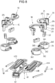
- Fig. 8
- eine Ansicht von Verschlussteilen der ersten Befestigungseinheit;
- Fig. 9A
- eine Ansicht einer einzelnen Verschlussvorrichtung der Verschlussbaugruppe, in einer Schließstellung;
- Fig. 9B
- eine Draufsicht auf die Anordnung gemäß
Fig. 9A ; - Fig. 9C
- eine Schnittansicht entlang der Linie A-A gemäß
Fig. 9B ; - Fig. 9D
- eine Seitenansicht der Anordnung gemäß
Fig. 9A ; - Fig. 9E
- eine teiltransparente Draufsicht auf die Anordnung gemäß
Fig. 9A ; - Fig. 10A
- eine Ansicht einer einzelnen Verschlussvorrichtung der Verschlussbaugruppe, beim Öffnen durch Betätigen eines Wirkelements;
- Fig. 10B
- eine Draufsicht auf die Anordnung gemäß
Fig. 10A ; - Fig. 10C
- eine Schnittansicht entlang der Linie A-A gemäß
Fig. 10B ; - Fig. 10D
- eine Seitenansicht der Anordnung gemäß
Fig. 10A ; - Fig. 10E
- eine teiltransparente Draufsicht auf die Anordnung gemäß
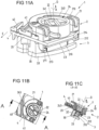
Fig. 10A ; - Fig. 11A
- eine Ansicht einer einzelnen Verschlussvorrichtung der Verschlussbaugruppe, beim weiteren Öffnen;
- Fig. 11B
- eine Draufsicht auf die Anordnung gemäß
Fig. 11A ; - Fig. 11C
- eine Schnittansicht entlang der Linie A-A gemäß
Fig. 11B ; - Fig. 11D
- eine Seitenansicht der Anordnung gemäß
Fig. 11A ; - Fig. 11E
- eine teiltransparente Draufsicht auf die Anordnung gemäß
Fig. 11A ; - Fig. 12A
- eine Ansicht einer einzelnen Verschlussvorrichtung der Verschlussbaugruppe, in einer geöffneten Stellung;
- Fig. 12B
- eine Draufsicht auf die Anordnung gemäß
Fig. 12A ; - Fig. 12C
- eine Schnittansicht entlang der Linie A-A gemäß
Fig. 12B ; - Fig. 12D
- eine Seitenansicht der Anordnung gemäß
Fig. 12A ; - Fig. 12E
- eine teiltransparente Draufsicht auf die Anordnung gemäß
Fig. 12A ; - Fig. 13
- eine vergrößerte Ausschnitt der Schnittansicht gemäß
Fig. 9C , darstellend die Verriegelung in der Schließstellung; - Fig. 14
- eine Explosionsansicht eines weiteren Ausführungsbeispiels einer Verschlussbaugruppe;
- Fig. 15
- eine Ansicht der Verschlussbaugruppe, in einer geöffneten Stellung;
- Fig. 16
- eine Ansicht der Verschlussbaugruppe, in einer Schließstellung;
- Fig. 17A
- eine Ansicht der Verschlussbaugruppe, in der Schließstellung;
- Fig. 17B
- eine Draufsicht auf die Verschlussbaugruppe;
- Fig. 17C
- eine Seitenansicht der Verschlussbaugruppe;
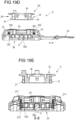
- Fig. 17D
- eine Schnittansicht entlang der Linie A-A gemäß
Fig. 17B ; - Fig. 17E
- eine Schnittansicht entlang der Linie B-B gemäß
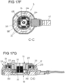
Fig. 17B ; - Fig. 17F
- eine Schnittansicht entlang der Linie C-C gemäß
Fig. 17C ; - Fig. 17G
- eine Schnittansicht entlang der Linie D-D gemäß
Fig. 17B ; - Fig. 18A
- eine Ansicht der Verschlussbaugruppe, beim Öffnen;
- Fig. 18B
- eine Draufsicht auf die Verschlussbaugruppe;
- Fig. 18C
- eine Seitenansicht der Verschlussbaugruppe;
- Fig. 18D
- eine Schnittansicht entlang der Linie A-A gemäß
Fig. 18B ; - Fig. 18E
- eine Schnittansicht entlang der Linie B-B gemäß
Fig. 18B ; - Fig. 18F
- eine Schnittansicht entlang der Linie C-C gemäß
Fig. 18C ; - Fig. 18G
- eine Schnittansicht entlang der Linie D-D gemäß
Fig. 18B ; - Fig. 19A
- eine Ansicht der Verschlussbaugruppe, beim weiteren Öffnen;
- Fig. 19B
- eine Draufsicht auf die Verschlussbaugruppe;
- Fig. 19C
- eine Seitenansicht der Verschlussbaugruppe;
- Fig. 19D
- eine Schnittansicht entlang der Linie A-A gemäß
Fig. 19B ; - Fig. 19E
- eine Schnittansicht entlang der Linie B-B gemäß
Fig. 19B ; - Fig. 19F
- eine Schnittansicht entlang der Linie C-C gemäß
Fig. 19C ; - Fig. 19G
- eine Schnittansicht entlang der Linie D-D gemäß
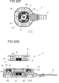
Fig. 19B ; - Fig. 20A
- eine Ansicht der Verschlussbaugruppe, in einer geöffneten Stellung;
- Fig. 20B
- eine Draufsicht auf die Verschlussbaugruppe;
- Fig. 20C
- eine Seitenansicht der Verschlussbaugruppe;
- Fig. 20D
- eine Schnittansicht entlang der Linie A-A gemäß
Fig. 20B ; - Fig. 20E
- eine Schnittansicht entlang der Linie B-B gemäß
Fig. 20B ; - Fig. 20F
- eine Schnittansicht entlang der Linie C-C gemäß
Fig. 20C ; - Fig. 20G
- eine Schnittansicht entlang der Linie D-D gemäß
Fig. 20B ; - Fig.21A
- eine gesonderte Ansicht einer Verriegelungsbaugruppe einer Befestigungseinheit der Verschlussbaugruppe, in einer verriegelten Stellung, von oben;
- Fig. 21B
- eine Ansicht der Verriegelungsbaugruppe der Befestigungseinheit der Verschlussbaugruppe, in der verriegelten Stellung, von unten;
- Fig. 21C
- eine ausschnittsweise vergrößerte Ansicht im Ausschnitt E gemäß
Fig. 21B ; - Fig. 22A
- eine Ansicht der Verriegelungsbaugruppe der Befestigungseinheit der Verschlussbaugruppe, in einer entriegelten Stellung, von oben;
- Fig. 22B
- eine Ansicht der Verriegelungsbaugruppe der Befestigungseinheit der Verschlussbaugruppe, in der verriegelten Stellung, von unten; und
- Fig. 22C
- eine vergrößerte Ansicht im Ausschnitt E gemäß
Fig. 22B ;
- Fig. 1
- a view of an exemplary embodiment of a closure assembly with a first fastening unit and second fastening unit, in a position of the fastening units separated from one another;
- Fig. 2
- another view of the shutter assembly;
- Fig. 3
- an exploded view of the closure assembly;
- Fig. 4
- a separate view of the second fastening unit;
- Fig. 5
- another view of the second fastening unit;
- Fig. 6
- a separate view of the first fastening unit;
- Fig. 7
- another view of the first fastening unit;
- Fig. 8
- a view of closure parts of the first fastening unit;
- Fig. 9A
- a view of an individual closure device of the closure assembly, in a closed position;
- Fig. 9B
- a top view of the arrangement according to
Fig. 9A ; - Fig. 9C
- a sectional view along line AA according to
Fig. 9B ; - Fig. 9D
- a side view of the arrangement
Fig. 9A ; - Fig. 9E
- a partially transparent top view of the arrangement
Fig. 9A ; - Fig. 10A
- a view of an individual closure device of the closure assembly, when opened by actuating an active element;
- Fig. 10B
- a top view of the arrangement according to
Fig. 10A ; - Fig. 10C
- a sectional view along line AA according to
Fig. 10B ; - Fig. 10D
- a side view of the arrangement
Fig. 10A ; - Fig. 10E
- a partially transparent top view of the arrangement
Fig. 10A ; - Fig. 11A
- a view of an individual closure device of the closure assembly, upon further opening;
- Fig. 11B
- a top view of the arrangement according to
Fig. 11A ; - Fig. 11C
- a sectional view along line AA according to
Fig. 11B ; - Fig. 11D
- a side view of the arrangement
Fig. 11A ; - Fig. 11E
- a partially transparent top view of the arrangement
Fig. 11A ; - Fig. 12A
- a view of a single locking device of the locking assembly, in an open position;
- Fig. 12B
- a top view of the arrangement according to
Fig. 12A ; - Fig. 12C
- a sectional view along line AA according to
Fig. 12B ; - Fig. 12D
- a side view of the arrangement
Fig. 12A ; - Fig. 12E
- a partially transparent top view of the arrangement
Fig. 12A ; - Fig. 13
- an enlarged detail of the sectional view
Fig. 9C , representing the lock in the closed position; - Fig. 14
- an exploded view of another embodiment of a closure assembly;
- Fig. 15
- a view of the closure assembly in an open position;
- Fig. 16
- a view of the closure assembly, in a closed position;
- Fig. 17A
- a view of the closure assembly, in the closed position;
- Fig. 17B
- a top view of the shutter assembly;
- Fig. 17C
- a side view of the closure assembly;
- Fig. 17D
- a sectional view along line AA according to
Fig. 17B ; - Fig. 17E
- a sectional view along line BB according to
Fig. 17B ; - Fig. 17F
- a sectional view along the line CC according to
Fig. 17C ; - Fig. 17G
- a sectional view along the line DD according to
Fig. 17B ; - Fig. 18A
- a view of the lock assembly when opened;
- Fig. 18B
- a top view of the shutter assembly;
- Fig. 18C
- a side view of the closure assembly;
- Fig. 18D
- a sectional view along line AA according to
Fig. 18B ; - Fig. 18E
- a sectional view along line BB according to
Fig. 18B ; - Fig. 18F
- a sectional view along the line CC according to
Fig. 18C ; - Fig. 18G
- a sectional view along the line DD according to
Fig. 18B ; - Fig. 19A
- a view of the closure assembly as it opens further;
- Fig. 19B
- a top view of the shutter assembly;
- Fig. 19C
- a side view of the closure assembly;
- Fig. 19D
- a sectional view along line AA according to
Fig. 19B ; - Fig. 19E
- a sectional view along line BB according to
Fig. 19B ; - Fig. 19F
- a sectional view along the line CC according to
Fig. 19C ; - Fig. 19G
- a sectional view along the line DD according to
Fig. 19B ; - Fig. 20A
- a view of the closure assembly in an open position;
- Fig. 20B
- a top view of the shutter assembly;
- Fig. 20C
- a side view of the closure assembly;
- Fig. 20D
- a sectional view along line AA according to
Fig. 20B ; - Fig. 20E
- a sectional view along line BB according to
Fig. 20B ; - Fig. 20F
- a sectional view along the line CC according to
Fig. 20C ; - Fig. 20G
- a sectional view along the line DD according to
Fig. 20B ; - Fig.21A
- a separate view of a locking assembly of a fastening unit of the locking assembly, in a locked position, from above;
- Fig. 21B
- a bottom view of the locking assembly of the fastening unit of the locking assembly in the locked position;
- Fig. 21C
- a partially enlarged view in section E according to
Fig. 21B ; - Fig. 22A
- a top view of the locking assembly of the fastening unit of the locking assembly in an unlocked position;
- Fig. 22B
- a bottom view of the locking assembly of the fastening unit of the locking assembly in the locked position; and
- Fig. 22C
- an enlarged view in detail E according to
Fig. 22B ;
Die Verschlussbaugruppe 5 kann beispielsweise zur Befestigung einer Tasche an einer übergeordneten Baugruppe, zum Beispiel an einem Fahrzeug, zum Beispiel einem Motorrad, Verwendung finden. Eine zu befestigende Baugruppe, zum Beispiel eine Tasche, kann hierbei beispielsweise mit der Befestigungseinheit 50 verbunden sein, während die Befestigungseinheit 51 an der übergeordneten Baugruppe, beispielsweise dem Fahrzeug, festgelegt ist, sodass über die Verschlussbaugruppe 5 die zu befestigende Baugruppe an der übergeordneten Baugruppe lösbar festgelegt werden kann.The
Wie aus
In dem Gehäuseteil 500 ist ein Betätigungselement 4 entlang einer Entriegelungsrichtung E verschiebbar gelagert, wobei ein Griff 42, wie aus
Die Verschlussbaugruppe 5 weist eine Mehrzahl von Verschlussvorrichtungen 1A-1D auf, die jeweils ein erstes Verschlussteil 2A-2D und ein zweites Verschlussteil 3A-3D umfassen und dazu dienen, die Befestigungseinheiten 50, 51 in der Schließstellung fest miteinander zu verriegeln, sodass die Befestigungseinheiten 50, 51 belastbar aneinander gehalten sind.The
Die ersten Verschlussteile 2A-2D, deren Funktion nachfolgend noch im Einzelnen erläutert werden soll, sind an der Befestigungseinheit 50 angeordnet und weisen, wie aus der Explosionsansicht gemäß
An einem Drehkörper 240 eines jeden Wirkelements 24 ist, wie zum Beispiel aus
Das Betätigungselement 4 ist über ein Federelement 43 gegenüber dem Gehäuseteil 500 federvorgespannt, sodass eine Betätigung des Betätigungselements 4 in die Entriegelungsrichtung E entgegen der Federvorspannung des als Zugfeder ausgebildeten Federelements 43 erfolgt und das Betätigungselement 4 nach einer erfolgten Betätigung selbsttätig aufgrund der Federvorspannung in eine nicht betätigte Ausgangsstellung zurückgestellt wird.The
Die zweiten Verschlussteile 3A-3D sind, wie zum Beispiel aus
Die Funktionsweise einer jeden Verschlussvorrichtung 1A-1D die soll nachfolgend anhand von
Die Verschlussvorrichtung 1, wie sie in
Das Wirkelement 24 weist einen Drehkörper 240 auf, der um eine Drehachse D zu dem Körper 20 drehbar ist. Das Wirkelement 24 ist über Führungseinrichtungen 242 in Form von diametral einander gegenüberliegenden, an einer außenseitigen, umfänglichen Mantelfläche des Drehkörpers 240 geformten Kulissenführungen (siehe hierzu zum Beispiel
Die Kulissenführungen 242 sind hierzu schräg zur Schließrichtung X erstreckt, wobei die Führungselemente 215, 216 bei einer Drehbewegung des Wirkelements 24 in den Kulissenführungen 242 gleiten und das Verstellteil 21 dadurch entlang der Betätigungsrichtung B bewegt wird.For this purpose, the link guides 242 are extended obliquely to the closing direction
Das Verriegelungselement 23 ist, zusätzlich zur Kopplung mit dem Verstellteil 21, in einer Aufnahmeöffnung 202 an einem an dem Körper 20 geformten, in die Schließrichtung X von dem Boden 503 der Befestigungseinheit 50 vorstehenden Stützelement 200 aufgenommen, wie dies aus einer Zusammenschau von
Zum Schließen der Verschlussrichtung 1 werden die Verschlussteile 2, 3 entlang der Schließrichtung X derart aneinander angesetzt, dass ein jedes Eingriffselement 31 an der Befestigungseinheit 51 in Eingriff mit dem jeweils zugeordneten Verriegelungselement 23 an der Befestigungseinheit 50 gelangt. Das Eingriffselement 31 drängt beim Ansetzen das Verriegelungselement 23 nach außen und somit in den Aufnahmeöffnungen 202 beiseite, sodass die Verschlussteile 2, 3 in die in
Ein jedes Verschlussteil 2, 3 weist hierbei eine Magneteinrichtung auf, die sich beim Ansetzen der Verschlussteile 2, 3 aneinander magnetisch anziehend gegenüberstehen, sodass das Ansetzen der Befestigungseinheiten 50, 51 aneinander zum Schließen der Verschlussbaugruppe 5 magnetisch unterstützt wird. Die Magneteinrichtungen 22, 32 können zum Beispiel jeweils durch einen Permanentmagneten ausgebildet sein, wobei sich die Magneteinrichtungen 22, 32 der einzelnen Verschlussteile 2, 3 mit ungleichnamigen Polen gegenüberstehen und somit magnetisch anziehend zusammenwirken. Denkbar ist auch, eine der Magneteinrichtungen 22, 32 durch einen Permanentmagneten und die andere Magneteinrichtung 32, 22 durch einen magnetischen Anker aus einem ferromagnetischen Material auszubilden.Each
Bei dem dargestellten Ausführungsbeispiel ist die Magneteinrichtung 22 des Verschlussteils 2 in einer Montageöffnung 241 innerhalb des Drehkörpers 240 des Wirkelements 24 aufgenommen, sodass die Magneteinrichtung 22 bei einem Verdrehen des Wirkelements 24 gemeinsam mit dem Wirkelement 24 um die Drehachse D verdrehbar ist.In the exemplary embodiment shown, the
Die Magneteinrichtung 32 des Verschlussteils 3 ist demgegenüber innerhalb der Basis 30 aufgenommen.The
Die Magneteinrichtung 32 des zweiten Verschlussteils 3 wirkt magnetisch anziehend mit dem Verriegelungselement 23 zusammen. Dies bewirkt, dass in der Schließstellung das Verriegelungselement 23 in Eingriff mit dem Eingriffsabschnitt 310 am Eingriffselement 31 gezogen wird, sodass darüber eine formschlüssige Verriegelung zwischen den Verschlussteilen 2, 3 hergestellt ist, wie dies aus
Werden die Verschlussteile 2, 3 zueinander belastet, so verkeilt das Verriegelungselement 23 zwischen einer Schrägfläche 311 an dem Eingriffsabschnitt 310 und einer gegenüberliegenden Schrägfläche 201 innerhalb der Aufnahmeöffnung 202 am Stützelement 200, wie dies aus
Sollen die Verschlussteile 2, 3 voneinander gelöst werden, so kann das Wirkelement 24 um die Drehachse D in die Drehrichtung A verdreht werden, indem das Betätigungselement 4 in die Entriegelungsrichtung E zu dem Gehäuseteil 500 der Befestigungseinheit 50 bewegt wird. Die Wirkelemente 24 sämtlicher Verschlussvorrichtungen 1A-1D der Verschlussbaugruppe 5 werden hierbei gemeinsam betätigt, bewirkt durch die Getriebeverbindung zwischen dem Betätigungselement 4 mit den einzelnen Wirkelementen 24.If the
Durch Verdrehen des Wirkelements 24 in die Drehrichtung A wird das Verstellteil 21 einer jeden Verschlussvorrichtung 1, wie dies aus
Weil bei einem Verdrehen des Wirkelements 24 auch die Magneteinrichtung 22 des Verschlussteils 2 mit verdreht wird, schwächt sich, wie dies beispielsweise aus der überlagerten, transparenten Ansicht gemäß
Die Verschlussteile 2, 3 können somit in einfacher Weise entgegen der Schließrichtung X voneinander gelöst werden, wie dies in
Unter Last erhöht sich hierbei die Kraft, die zum Verschieben des Verstellteils 21 notwendig ist.Under load, the force required to move the adjusting
Dadurch, dass die Befestigungseinheiten 50, 51 der Verschlussbaugruppe 5 über mehrere Verschlussvorrichtungen 1A-1D einander verbunden sind, ergibt sich eine feste, belastbare Mehrpunkt-Verbindung in der Schließstellung.The fact that the
Das Öffnen der Verschlussvorrichtung 1 ist einfach und komfortabel. Insbesondere kann ein Nutzer zum Öffnen einfach das Betätigungselement 4 am Griff 42 greifen und in die Entriegelungsrichtung E ziehen. Die Verschlussvorrichtungen 1A-1D können hierdurch gemeinsam geöffnet werden, sodass die Befestigungseinheiten 50, 51 entgegen der Schließrichtung X voneinander gelöst werden können.Opening the
Ein weiteres Ausführungsbeispiel einer Verschlussbaugruppe 5 ist in
Bei diesem Ausführungsbeispiel weist eine Verschlussbaugruppe 5 Befestigungseinheiten 50, 51 auf, die aneinander angesetzt werden können, um eine Verbindung zwischen den Befestigungseinheiten 50, 51 und somit von mit den Befestigungseinheit 50, 51 verbundenen Baugruppen herzustellen.In this exemplary embodiment, a
Bei dem dargestellten Ausführungsbeispiel weist eine erste Befestigungseinheit 50 ein durch Gehäuseteile 500, 501 gebildetes Gehäuse auf, das eine Verriegelungsbaugruppe 25 einfasst. Die Verriegelungsbaugruppe 25 bildet hierbei Verschlussvorrichtungen 2A-2D aus, die jeweils ein Verriegelungselement 23 aufweisen, das an zugeordneten Stützelementen 200 in Form von von einem Scheibenkörper 250 vorstehenden Laschen angeordnet und in Aufnahmeöffnungen 202 in Form von Langlöchern an den Stützelementen 200 geführt ist.In the exemplary embodiment shown, a
Verstellteile 21 der Verschlussvorrichtungen 2A-2D sind bei dem dargestellten Ausführungsbeispiel durch eine Anordnung von Schiebeelement 217 ausgebildet, die an dem Gehäuseteil 500 des Gehäuses geführt sind und Lageröffnungen 213, 214 zum Einwirken auf Enden der Verriegelungselemente 23 aufweisen.Adjusting
An dem Gehäuseteil 501 ist ein Wirkelement 24 um eine Drehachse D drehbar gelagert, das den Verschlussvorrichtungen 2A-2D gemeinsam zugeordnet ist und Führungseinrichtungen 242 zum Zusammenwirken mit den Schiebeelementen 217 ausbildet. Das Wirkelement 24 ist an einem Lagerelement 504 des Gehäuseteils 501 gelagert und kann verdreht werden, um die Schiebeelemente 217 gemeinsam zu verstellen und dadurch auf die Verriegelungselemente 23 einzuwirken.On the
Ein Betätigungselement 4 weist einen Verstellkörper 40 in Form eines längserstreckten Stabes auf, der mit einem Griff 42 gekoppelt ist, an dem ein Nutzer zum Betätigen des Betätigungselements 40 angreifen kann. Das Betätigungselement 4 ist zwischen den Gehäuseteilen 500, 501 entlang einer Entriegelungsrichtung E verschiebbar geführt und ist über ein Kopplungselement 400 in Form eines Kopplungszapfens derart mit dem Wirkelement 24 gekoppelt, dass durch Längsverschieben des Betätigungselements 4 das Wirkelement 24 um die Drehachse D verdreht werden kann, um auf diese Weise die Schiebeelemente 217 zu verstellen.An
Eine zweite Befestigungseinheit 51 ist durch einen Körper 30 gebildet, an dem Verschlussteile 3A-3D mit jeweils einem Eingriffselement 31 in Form eines durch einen Vorsprung begrenzten Eingriffsabschnitts 310 geformt sind. Einem jeden Verschlussteil 2A-2D der Befestigungseinheit 50 ist hierbei ein Verschlussteil 3A, 3D der Befestigungseinheit 51 zugeordnet.A
An dem Wirkelement 24 sind Magnetelemente 22 in Form von einer Anordnung von Permanentmagneten angeordnet. Die Magnetelemente 22 sind der Befestigungseinheit 50 zugeordnet. An dem Körper 30 der Befestigungseinheit 51 sind Magnetelemente 32 in Form von einer Anordnung von Permanentmagneten angeordnet. Durch Wechselwirkung der Magnetelemente 22, 32 erfolgt das Ansetzen der Befestigungseinheiten 50, 51 zur Herstellung einer verriegelten Verbindung zwischen den Verschlussteilen 2A-2D, 3A-3D in magnetisch unterstützter Weise.
Die Verriegelungselemente 23 sind magnetisch und werden durch magnetische Wechselwirkung mit den Magnetelementen 32 der Befestigungseinheit 51 selbsttätig in Eingriff mit den Eingriffselementen 31 gezogen, wie dies aus
In der Schließstellung sind die Schiebeelemente 217 gegenüber dem Wirkelement 24 in Richtung der Befestigungseinheit 51 angehoben, wie dies aus
Zum Öffnen der Verschlussbaugruppe 5 wird das Betätigungselement 4 über den Griff 42 in die Entriegelungsrichtung E betätigt. Aufgrund der Kopplung des Betätigungselements 4 über das Kopplungselement 400 mit dem Wirkelement 24 wird das Wirkelement 24 um die Drehachse D verdreht, wie dies insbesondere aus
Dadurch wirkt das Wirkelement 24 auf die Schiebeelemente 217 ein, indem Führungseinrichtungen 242 des Wirkelements 24 auf Führungszapfen 215 an den Schiebeelementen 217 einwirken und die Schiebeelemente 217 dadurch in eine Betätigungsrichtung B nach unten ziehen, wie dies aus
Bei Betätigen des Wirkelements 24 werden die Magnetelemente 22 zudem gemeinsam mit dem Wirkelement 24 verdreht, sodass die Magnetelemente 22 aus ihrer Gegenüberlage mit den Magnetelementen 32 gebracht werden, wie dies aus
Die Befestigungseinheiten 50, 51 können, nach Entriegelung über das Betätigungselement 4, somit voneinander abgenommen werden, wie dies in
Nach dem Öffnen der Verschlussbaugruppe und nach dem Loslassen des Griffs 42 gelangt das Betätigungselement 4 zurück in seine nicht betätigte Stellung, dargestellt in
Die Verschlussbaugruppe 5 befindet sich somit in einer geöffneten Stellung. Durch erneutes Ansetzen der Befestigungseinheiten 50, 51 kann die Verschlussbaugruppe 5 wieder geschlossen werden.The
An einem jeden Schiebeelement 217, die gemeinsam die Verstellteile 21 der Verschlussteile 2A-2D ausbilden, ist ein nach innen weisender Führungszapfen 215 geformt, der zum Zusammenwirken mit den Führungseinrichtungen 242 des Wirkelements 24 dient. Einem jeden Schiebeelement 217 ist hierbei eine Führungseinrichtung 242 am äußeren Umfang des Wirkelements 24 zugeordnet, sodass die Schiebeelemente 217 gemeinsam durch Verdrehen des Wirkelements 24 um die Drehachse D verdreht werden können.On each sliding
Wie dies aus
In der Schließstellung, entsprechend den Ansichten gemäß
Die Schiebeelemente 217 werden hierbei durch die Auflaufschrägen 246 in der angehobenen Stellung gehalten. Zusätzlich oder alternativ werden die Schiebeelemente 217 mit den Verriegelungselementen 23 in die angehobene Stellung bewegt und dort gehalten. Die Verriegelungselemente 23 bewegen sich hierbei aufgrund magnetischer Wechselwirkung mit den Magnetelementen 22 an dem Wirkelement 24 in die obere, nach innen versetzte Verriegelungsstellung.The sliding
Wird das Wirkelement 24 zum Betätigen der Schiebeelemente 217 verdreht, wie dies aus
Während bei dem Ausführungsbeispiel gemäß
Der der Erfindung zugrunde liegende Gedanke ist nicht auf die vorangehend geschilderten Ausführungsbeispiele beschränkt, sondern lässt sich auch in anderer Weise verwirklichen.The idea on which the invention is based is not limited to the exemplary embodiments described above, but can also be implemented in other ways.
Eine Verschlussvorrichtung der beschriebenen Art kann in ganz unterschiedlicher Weise Verwendung finden.A closure device of the type described can be used in very different ways.
So kann eine Verschlussbaugruppe zur Verbindung einer Baugruppe, zum Beispiel einer Tasche, mit einer übergeordneten Baugruppe, zum Beispiel einem Fahrzeug Verwendung finden. Beispielsweise kann über eine Verschlussbaugruppe eine Tasche an einem Tank eines Motorrads zu befestigen sein.A closure assembly can be used to connect an assembly, for example a bag, to a higher-level assembly, for example a vehicle. For example, a bag can be attached to a tank of a motorcycle via a closure assembly.
Eine Verschlussvorrichtung der beschriebenen Art kann zudem zum Verbinden eines elektronischen Geräts mit einer übergeordneten Baugruppe, zum Beispiel in oder an einem Fahrzeug, zum Beispiel einem Kraftfahrzeug oder Fahrrad, Verwendung finden. So kann über eine solche Vorrichtung beispielsweise ein Mobiltelefon an einem Armaturenbrett eines Kraftfahrzeugs oder an einer Lenkerstange eines Fahrrads (lösbar) festgelegt werden.A closure device of the type described can also be used to connect an electronic device to a higher-level assembly, for example in or on a vehicle, for example a motor vehicle or bicycle. For example, a mobile phone can be attached (releasably) to a dashboard of a motor vehicle or to a handlebar of a bicycle using such a device.
Die Verschlussvorrichtung kann aber auch zum Verbinden anderer Gegenstände miteinander, zum Beispiel als Verschluss für einen Helm, insbesondere Sporthelm, für eine Tasche oder für ein Kleidungsstück, Verwendung finden.The closure device can also be used to connect other objects to one another, for example as a closure for a helmet, in particular a sports helmet, for a bag or for a piece of clothing.
- 1, 1A-D1, 1A-D
- VerschlussvorrichtungClosure device
- 2, 2A-D2, 2A-D
- VerschlussteilClosure part
- 2020
- KörperBody
- 200200
- StützelementSupport element
- 201201
- Schrägflächeinclined surface
- 202202
- AufnahmeöffnungRecording opening
- 2121
- VerstellteilAdjustment part
- 210210
- Körperelementbody element
- 211,212211,212
- LagerarmBearing arm
- 213, 214213, 214
- LageröffnungWarehouse opening
- 215, 216215, 216
- Führungselement (Führungszapfen)Guide element (guide pin)
- 217217
- SchiebeelementSliding element
- 2222
- MagneteinrichtungMagnet device
- 2323
- VerriegelungselementLocking element
- 2424
- WirkelementActive element
- 240240
- Drehkörperrotating body
- 241241
- MontageöffnungAssembly opening
- 242242
- FührungseinrichtungManagement facility
- 243243
- Verzahnunggearing
- 244244
- KopplungsöffnungCoupling opening
- 245245
- Aussparungrecess
- 246, 247246, 247
- Auflaufschrägecasserole slope
- 2525
- VerriegelungsbaugruppeLocking assembly
- 250250
- KörperBody
- 3, 3A-D3, 3A-D
- VerschlussteilClosure part
- 3030
- BasisBase
- 3131
- EingriffselementIntervention element
- 310310
- EingriffsabschnittIntervention section
- 311311
- Schrägflächeinclined surface
- 3232
- MagneteinrichtungMagnet device
- 3333
- Befestigungsplattemounting plate
- 44
- BetätigungselementActuator
- 4040
- VerstellkörperAdjusting body
- 400400
- Kopplungselement (Kopplungszapfen)Coupling element (coupling pin)
- 41, 41A-D41, 41A-D
- VerzahnungsabschnittGear section
- 4242
- GriffHandle
- 4343
- FederelementSpring element
- 55
- VerschlussbaugruppeShutter assembly
- 5050
- BefestigungseinheitFastening unit
- 500500
- GehäuseteilHousing part
- 501501
- DeckelLid
- 502A-D502A-D
- LageraufnahmeStorage recording
- 503503
- BodenFloor
- 504504
- Lagerelement (Lagerzapfen)Bearing element (bearing journal)
- 5151
- BefestigungseinheitFastening unit
- AA
- DrehrichtungDirection of rotation
- Bb
- BetätigungsrichtungDirection of operation
- CC
- BetätigungsrichtungDirection of operation
- DD
- DrehachseAxis of rotation
- EE
- EntriegelungsrichtungUnlocking direction
- XX
- SchließrichtungClosing direction
Claims (15)
- Closure device (1, 1A-1D) havinga first closure part (2, 2A-2D) which has a body (20), and a second closure part (3, 3A-3D), said first closure part (2, 2A-2D) and said second closure part (3, 3A-3D) for closing the closure device (1, 1A-1D) being able to be placed against one another along a closing direction (X) and in a closing position being connected to one another; andat least one locking element (23) which is adjustable in relation to the body (20) of the first closure part (2, 2A-2D); andat least one engagement portion (310) which is shaped on the second closure part (3, 3A-3D), wherein the at least one locking element (23) and the at least one engagement portion (310) in a closing position are mutually engaged in such a manner that the first closure part (2, 2A-2D) and the second closure part (3, 3A-3D) are locked to one another,wherein the first closure part (2, 2A-2D) has a first magnetic installation (22), and the second closure part (3, 3A-3D) has a second magnetic installation (32), wherein the first magnetic installation (22) and the second magnetic installation (32) when placing the first closure part (2, 2A-2D) and the second closure part (3, 3A-3D) against one another interact in a magnetically attractive manner, and the at least one locking element (23) is magnetically configured in such a manner that the at least one locking element (23) in the closing position by way of the first magnetic installation (22) and/or the second magnetic installation (32) is loaded in the direction of engaging with the at least one engagement portion (310), wherein the first closure part (2, 2A-2D) has an adjustment part (21) and an operative element (24) which is operatively connected to the adjustment part (21) and is rotatable about a rotation axis (D), wherein the adjustment part (21) by rotating the operative element (24) is activatable in an activation direction (B) so as to bring the at least one locking element (23) to disengage from the at least one engagement portion (310) in order for the first closure part (2, 2A-2D) and the second closure part (3, 3A-3D) to be released from one another,characterized in thatthe engagement portion (310) has a first oblique face (311) which extends obliquely to the closing direction (X), and the first closure part (2, 2A-2D) has a second oblique face (201) which extends obliquely to the closing direction (X), wherein the at least one locking element (23) in the closing position is disposed between the first oblique face (311) and the second oblique face (201).
- Closure device (1, 1A-1D) according to Claim 1, characterized in that the rotation axis (D) is directed along the closing direction (X).
- Closure device (1, 1A-1D) according to Claim 1 or 2, characterized in that the activation direction (B) is directed along the rotation axis (D).
- Closure device (1, 1A-1D) according to one of Claims 1 to 3, characterized in that the operative element (24) has a guiding installation (242) on which the adjustment part (21) is guided in such a manner that the adjustment part (21) when rotating the operative element (24) is activated in the activation direction (B).
- Closure device (1, 1A-1D) according to Claim 4, characterized in that the guiding installation (242) is configured by a gate guide or at least one ramp (246, 247).
- Closure device (1) according to one of the preceding claims, characterized in that the at least one locking element (23) is received so as to be adjustable in a receptacle opening (202) of the first closure part (2).
- Closure device (1) according to Claim 6, characterized in that the receptacle opening (202) in relation to the closing direction (X) extends obliquely in such a manner that the at least one locking element (23) in the receptacle opening (202) is adjustable along an adjustment direction which extends obliquely to the closing direction (X).
- Closure device (1, 1A-1D) according to one of the preceding claims, characterized in that the at least one locking element (23) is disposed on the adjustment part (21).
- Closure device (1, 1A-1D) according to Claim 8, characterized in that the at least one locking element (23) on the adjustment part (21) is received in a bearing opening (211, 212) of the adjustment part (21) and in relation to the adjustment part (21) is adjustable transversely to the closing direction (X).
- Closure device (1, 1A-1D) according to one of the preceding claims, characterized in that the first oblique face (311) and the second oblique face (201) in a plane which is spanned by the closing direction (X) and a transverse direction (Q) are disposed parallel or at an angle which is greater than zero or less than zero..
- Closure device (1, 1A-1D) according to one of the preceding claims, characterized in that the at least one locking element (23) is configured as an elongate bar element.
- Closure device (1, 1A-1D) according to one of the preceding claims, characterized in that the first magnetic installation (22) is disposed on the operative element (24) and is rotatable conjointly with the operative element (24).
- Closure device (1, 1A-1D) according to one of the preceding claims, characterized in that, when rotating the operative element (24) from a rotary position assigned to the closing position, a magnetic pull between the first magnetic installation (22) and the second magnetic installation (32) is weakened.
- Closure device (1, 1A-1D) according to one of the preceding claims, characterized in that the second closure part (3, 3A-3D) has a base unit (30) on which the at least one engagement portion (310) is disposed.
- Closure assembly (5) having a plurality of closure devices (1, 1A-1D) according to one of the preceding claims.
Applications Claiming Priority (2)
| Application Number | Priority Date | Filing Date | Title |
|---|---|---|---|
| DE102019215277.5A DE102019215277A1 (en) | 2019-10-02 | 2019-10-02 | Closure device with closure parts that can be attached to one another |
| PCT/EP2020/077328 WO2021064002A1 (en) | 2019-10-02 | 2020-09-30 | Fastening apparatus comprising fastening parts which can be placed against one another |
Publications (2)
| Publication Number | Publication Date |
|---|---|
| EP3827178A1 EP3827178A1 (en) | 2021-06-02 |
| EP3827178B1 true EP3827178B1 (en) | 2024-02-28 |
Family
ID=72744552
Family Applications (2)
| Application Number | Title | Priority Date | Filing Date |
|---|---|---|---|
| EP20199214.6A Active EP3800360B1 (en) | 2019-10-02 | 2020-09-30 | Locking device with attaching locking parts |
| EP20792926.6A Active EP3827178B1 (en) | 2019-10-02 | 2020-09-30 | Fastening apparatus comprising fastening parts which can be placed against one another |
Family Applications Before (1)
| Application Number | Title | Priority Date | Filing Date |
|---|---|---|---|
| EP20199214.6A Active EP3800360B1 (en) | 2019-10-02 | 2020-09-30 | Locking device with attaching locking parts |
Country Status (7)
| Country | Link |
|---|---|
| US (1) | US11889901B2 (en) |
| EP (2) | EP3800360B1 (en) |
| JP (1) | JP2022550493A (en) |
| CN (1) | CN113056216A (en) |
| DE (1) | DE102019215277A1 (en) |
| TW (1) | TWI766385B (en) |
| WO (1) | WO2021064002A1 (en) |
Families Citing this family (3)
| Publication number | Priority date | Publication date | Assignee | Title |
|---|---|---|---|---|
| DE102020207310B4 (en) * | 2020-06-11 | 2021-12-30 | Fidlock Gmbh | Locking device secured under load |
| DE102022104735B3 (en) * | 2022-02-28 | 2023-06-07 | Fidlock Gmbh | Locking device for connecting two assemblies |
| DE102022104734B3 (en) * | 2022-02-28 | 2023-06-01 | Fidlock Gmbh | Locking device for connecting two assemblies |
Family Cites Families (17)
| Publication number | Priority date | Publication date | Assignee | Title |
|---|---|---|---|---|
| DE2656511C2 (en) * | 1976-12-14 | 1985-08-29 | Naamloze Vennootschap Nederlandsche Apparatenfabriek Nedap, Groenlo | Fastening device |
| US6000306A (en) * | 1998-06-12 | 1999-12-14 | Kennametal Inc. | Side activated tool unit clamping apparatus using mechanical advantage |
| JP2944643B1 (en) * | 1998-07-09 | 1999-09-06 | 有限会社ターモ | Magnetic stop |
| US6182336B1 (en) | 1999-02-18 | 2001-02-06 | Irving Bauer | Magnetic safety snap locking device and method of fastening the device with manual resetting |
| US6295702B1 (en) | 2000-09-15 | 2001-10-02 | Irving Bauer | Locking magnetic fastener |
| DE102004015873B4 (en) * | 2004-03-31 | 2007-03-22 | Joachim Fiedler | Detachable magnetic holder |
| AU2007272165B2 (en) * | 2006-07-12 | 2012-10-04 | Fidlock Gmbh | Mechanic-magnetic connecting structure |
| WO2009006888A2 (en) * | 2007-07-12 | 2009-01-15 | Fidlock Gmbh | Magnetic closure with an opening-assisting spring |
| DE102007058188A1 (en) * | 2007-12-04 | 2009-06-10 | Fidlock Gmbh | Magnetic coupling device |
| EP2252176B1 (en) * | 2008-01-27 | 2015-04-15 | Fidlock Gmbh | Locking magnet closure |
| DE202010010300U1 (en) * | 2009-08-24 | 2010-10-21 | Fidlock Gmbh | Mechanical lock with a locking device |
| DE102010044144B3 (en) * | 2010-11-18 | 2012-05-31 | Fidlock Gmbh | closure device |
| US9869423B2 (en) * | 2013-03-15 | 2018-01-16 | Otter Products, Llc | Releasable mount apparatus and system with lock switch |
| DE102016216422A1 (en) * | 2016-08-31 | 2018-03-01 | Fidlock Gmbh | Closure device for connecting a container e.g. on a bicycle |
| WO2018073064A1 (en) * | 2016-10-19 | 2018-04-26 | Axel Tietz | Magnetic key lock, magnetic key, and combination of same |
| DE102017212151A1 (en) * | 2017-07-14 | 2019-01-17 | Fidlock Gmbh | Closure device with electrical contacts |
| DE102018201021A1 (en) | 2017-11-14 | 2019-05-16 | Fidlock Gmbh | Closure device with a winding element |
-
2019
- 2019-10-02 DE DE102019215277.5A patent/DE102019215277A1/en active Pending
-
2020
- 2020-09-30 EP EP20199214.6A patent/EP3800360B1/en active Active
- 2020-09-30 EP EP20792926.6A patent/EP3827178B1/en active Active
- 2020-09-30 JP JP2021518758A patent/JP2022550493A/en active Pending
- 2020-09-30 US US17/277,336 patent/US11889901B2/en active Active
- 2020-09-30 TW TW109134269A patent/TWI766385B/en active
- 2020-09-30 CN CN202080006254.8A patent/CN113056216A/en active Pending
- 2020-09-30 WO PCT/EP2020/077328 patent/WO2021064002A1/en unknown
Also Published As
| Publication number | Publication date |
|---|---|
| TW202129160A (en) | 2021-08-01 |
| CN113056216A (en) | 2021-06-29 |
| EP3800360B1 (en) | 2023-03-01 |
| DE102019215277A1 (en) | 2021-04-08 |
| EP3800360A1 (en) | 2021-04-07 |
| US20220312904A1 (en) | 2022-10-06 |
| EP3827178A1 (en) | 2021-06-02 |
| JP2022550493A (en) | 2022-12-02 |
| TWI766385B (en) | 2022-06-01 |
| US11889901B2 (en) | 2024-02-06 |
| WO2021064002A1 (en) | 2021-04-08 |
Similar Documents
| Publication | Publication Date | Title |
|---|---|---|
| EP3827178B1 (en) | Fastening apparatus comprising fastening parts which can be placed against one another | |
| EP4014782B1 (en) | Closure device with closure parts which can be connected to each other | |
| EP3857075B1 (en) | Closure device with closure parts which can be placed against each other | |
| EP2389084B1 (en) | Closure device for connecting two parts | |
| EP3791075B1 (en) | Closure device for connecting two assemblies to one another | |
| EP3943762B1 (en) | Connection device for releasably connecting two parts | |
| DE3126760C2 (en) | Device for re-setting the key secret in a permutation lock for suitcases or the like | |
| EP3996542B1 (en) | Closing apparatus with two closure parts which can be connected to a housing module | |
| EP1978843B1 (en) | Pivotal fitting | |
| DE102005014701A1 (en) | Locking system for a movable closing element | |
| EP1574641B1 (en) | Locking device for containers, doors, cabinets, furniture or the like. | |
| DE102022207115B3 (en) | Closure device | |
| DE102022104735B3 (en) | Locking device for connecting two assemblies | |
| DE102022203588A1 (en) | Closure device | |
| WO2023194121A1 (en) | Closure device | |
| DE4019702A1 (en) | Releaseable latching system for component motion - has eccentrically mounted wheels to jam component in one direction | |
| DE202019005390U1 (en) | Locking device for connecting two assemblies together | |
| WO2023160853A1 (en) | Closure device for connecting two assemblies | |
| WO2023160855A1 (en) | Closure device for connecting two assemblies | |
| DE212020000789U1 (en) | Support unit for a bicycle carrier | |
| CH92359A (en) | Device for locking an organ to be secured against unauthorized movement, e.g. a control shaft. | |
| DE3205266A1 (en) | Container valve with ancillary actuating device |
Legal Events
| Date | Code | Title | Description |
|---|---|---|---|
| STAA | Information on the status of an ep patent application or granted ep patent |
Free format text: STATUS: UNKNOWN |
|
| STAA | Information on the status of an ep patent application or granted ep patent |
Free format text: STATUS: THE INTERNATIONAL PUBLICATION HAS BEEN MADE |
|
| PUAI | Public reference made under article 153(3) epc to a published international application that has entered the european phase |
Free format text: ORIGINAL CODE: 0009012 |
|
| STAA | Information on the status of an ep patent application or granted ep patent |
Free format text: STATUS: REQUEST FOR EXAMINATION WAS MADE |
|
| 17P | Request for examination filed |
Effective date: 20210224 |
|
| AK | Designated contracting states |
Kind code of ref document: A1 Designated state(s): AL AT BE BG CH CY CZ DE DK EE ES FI FR GB GR HR HU IE IS IT LI LT LU LV MC MK MT NL NO PL PT RO RS SE SI SK SM TR |
|
| REG | Reference to a national code |
Ref country code: HK Ref legal event code: DE Ref document number: 40047616 Country of ref document: HK |
|
| DAV | Request for validation of the european patent (deleted) | ||
| DAX | Request for extension of the european patent (deleted) | ||
| GRAP | Despatch of communication of intention to grant a patent |
Free format text: ORIGINAL CODE: EPIDOSNIGR1 |
|
| STAA | Information on the status of an ep patent application or granted ep patent |
Free format text: STATUS: GRANT OF PATENT IS INTENDED |
|
| INTG | Intention to grant announced |
Effective date: 20230515 |
|
| GRAJ | Information related to disapproval of communication of intention to grant by the applicant or resumption of examination proceedings by the epo deleted |
Free format text: ORIGINAL CODE: EPIDOSDIGR1 |
|
| STAA | Information on the status of an ep patent application or granted ep patent |
Free format text: STATUS: REQUEST FOR EXAMINATION WAS MADE |
|
| P01 | Opt-out of the competence of the unified patent court (upc) registered |
Effective date: 20230821 |
|
| INTC | Intention to grant announced (deleted) | ||
| GRAP | Despatch of communication of intention to grant a patent |
Free format text: ORIGINAL CODE: EPIDOSNIGR1 |
|
| STAA | Information on the status of an ep patent application or granted ep patent |
Free format text: STATUS: GRANT OF PATENT IS INTENDED |
|
| INTG | Intention to grant announced |
Effective date: 20231205 |
|
| GRAS | Grant fee paid |
Free format text: ORIGINAL CODE: EPIDOSNIGR3 |
|
| GRAA | (expected) grant |
Free format text: ORIGINAL CODE: 0009210 |
|
| STAA | Information on the status of an ep patent application or granted ep patent |
Free format text: STATUS: THE PATENT HAS BEEN GRANTED |
|
| AK | Designated contracting states |
Kind code of ref document: B1 Designated state(s): AL AT BE BG CH CY CZ DE DK EE ES FI FR GB GR HR HU IE IS IT LI LT LU LV MC MK MT NL NO PL PT RO RS SE SI SK SM TR |
|
| REG | Reference to a national code |
Ref country code: GB Ref legal event code: FG4D Free format text: NOT ENGLISH |
|
| REG | Reference to a national code |
Ref country code: CH Ref legal event code: EP |
|
| REG | Reference to a national code |
Ref country code: DE Ref legal event code: R096 Ref document number: 502020007192 Country of ref document: DE |
|
| REG | Reference to a national code |
Ref country code: IE Ref legal event code: FG4D Free format text: LANGUAGE OF EP DOCUMENT: GERMAN |