EP3826839B1 - Dekoratives designelement im schwarzdruck - Google Patents
Dekoratives designelement im schwarzdruck Download PDFInfo
- Publication number
- EP3826839B1 EP3826839B1 EP19740397.5A EP19740397A EP3826839B1 EP 3826839 B1 EP3826839 B1 EP 3826839B1 EP 19740397 A EP19740397 A EP 19740397A EP 3826839 B1 EP3826839 B1 EP 3826839B1
- Authority
- EP
- European Patent Office
- Prior art keywords
- laminated glass
- design element
- pane
- black
- Prior art date
- Legal status (The legal status is an assumption and is not a legal conclusion. Google has not performed a legal analysis and makes no representation as to the accuracy of the status listed.)
- Active
Links
Images

Classifications
-
- B—PERFORMING OPERATIONS; TRANSPORTING
- B32—LAYERED PRODUCTS
- B32B—LAYERED PRODUCTS, i.e. PRODUCTS BUILT-UP OF STRATA OF FLAT OR NON-FLAT, e.g. CELLULAR OR HONEYCOMB, FORM
- B32B17/00—Layered products essentially comprising sheet glass, or glass, slag, or like fibres
- B32B17/06—Layered products essentially comprising sheet glass, or glass, slag, or like fibres comprising glass as the main or only constituent of a layer, next to another layer of a specific material
- B32B17/10—Layered products essentially comprising sheet glass, or glass, slag, or like fibres comprising glass as the main or only constituent of a layer, next to another layer of a specific material of synthetic resin
- B32B17/10005—Layered products essentially comprising sheet glass, or glass, slag, or like fibres comprising glass as the main or only constituent of a layer, next to another layer of a specific material of synthetic resin laminated safety glass or glazing
- B32B17/10165—Functional features of the laminated safety glass or glazing
- B32B17/10339—Specific parts of the laminated safety glass or glazing being colored or tinted
- B32B17/10357—Specific parts of the laminated safety glass or glazing being colored or tinted comprising a tinted intermediate film
-
- B—PERFORMING OPERATIONS; TRANSPORTING
- B32—LAYERED PRODUCTS
- B32B—LAYERED PRODUCTS, i.e. PRODUCTS BUILT-UP OF STRATA OF FLAT OR NON-FLAT, e.g. CELLULAR OR HONEYCOMB, FORM
- B32B17/00—Layered products essentially comprising sheet glass, or glass, slag, or like fibres
- B32B17/06—Layered products essentially comprising sheet glass, or glass, slag, or like fibres comprising glass as the main or only constituent of a layer, next to another layer of a specific material
- B32B17/10—Layered products essentially comprising sheet glass, or glass, slag, or like fibres comprising glass as the main or only constituent of a layer, next to another layer of a specific material of synthetic resin
- B32B17/10005—Layered products essentially comprising sheet glass, or glass, slag, or like fibres comprising glass as the main or only constituent of a layer, next to another layer of a specific material of synthetic resin laminated safety glass or glazing
- B32B17/10009—Layered products essentially comprising sheet glass, or glass, slag, or like fibres comprising glass as the main or only constituent of a layer, next to another layer of a specific material of synthetic resin laminated safety glass or glazing characterized by the number, the constitution or treatment of glass sheets
- B32B17/10036—Layered products essentially comprising sheet glass, or glass, slag, or like fibres comprising glass as the main or only constituent of a layer, next to another layer of a specific material of synthetic resin laminated safety glass or glazing characterized by the number, the constitution or treatment of glass sheets comprising two outer glass sheets
-
- B—PERFORMING OPERATIONS; TRANSPORTING
- B32—LAYERED PRODUCTS
- B32B—LAYERED PRODUCTS, i.e. PRODUCTS BUILT-UP OF STRATA OF FLAT OR NON-FLAT, e.g. CELLULAR OR HONEYCOMB, FORM
- B32B17/00—Layered products essentially comprising sheet glass, or glass, slag, or like fibres
- B32B17/06—Layered products essentially comprising sheet glass, or glass, slag, or like fibres comprising glass as the main or only constituent of a layer, next to another layer of a specific material
- B32B17/10—Layered products essentially comprising sheet glass, or glass, slag, or like fibres comprising glass as the main or only constituent of a layer, next to another layer of a specific material of synthetic resin
- B32B17/10005—Layered products essentially comprising sheet glass, or glass, slag, or like fibres comprising glass as the main or only constituent of a layer, next to another layer of a specific material of synthetic resin laminated safety glass or glazing
- B32B17/10165—Functional features of the laminated safety glass or glazing
- B32B17/10247—Laminated safety glass or glazing containing decorations or patterns for aesthetic reasons
-
- B—PERFORMING OPERATIONS; TRANSPORTING
- B32—LAYERED PRODUCTS
- B32B—LAYERED PRODUCTS, i.e. PRODUCTS BUILT-UP OF STRATA OF FLAT OR NON-FLAT, e.g. CELLULAR OR HONEYCOMB, FORM
- B32B17/00—Layered products essentially comprising sheet glass, or glass, slag, or like fibres
- B32B17/06—Layered products essentially comprising sheet glass, or glass, slag, or like fibres comprising glass as the main or only constituent of a layer, next to another layer of a specific material
- B32B17/10—Layered products essentially comprising sheet glass, or glass, slag, or like fibres comprising glass as the main or only constituent of a layer, next to another layer of a specific material of synthetic resin
- B32B17/10005—Layered products essentially comprising sheet glass, or glass, slag, or like fibres comprising glass as the main or only constituent of a layer, next to another layer of a specific material of synthetic resin laminated safety glass or glazing
- B32B17/10165—Functional features of the laminated safety glass or glazing
- B32B17/10247—Laminated safety glass or glazing containing decorations or patterns for aesthetic reasons
- B32B17/10256—Laminated safety glass or glazing containing decorations or patterns for aesthetic reasons created by printing techniques
- B32B17/10266—Laminated safety glass or glazing containing decorations or patterns for aesthetic reasons created by printing techniques on glass pane
-
- B—PERFORMING OPERATIONS; TRANSPORTING
- B32—LAYERED PRODUCTS
- B32B—LAYERED PRODUCTS, i.e. PRODUCTS BUILT-UP OF STRATA OF FLAT OR NON-FLAT, e.g. CELLULAR OR HONEYCOMB, FORM
- B32B17/00—Layered products essentially comprising sheet glass, or glass, slag, or like fibres
- B32B17/06—Layered products essentially comprising sheet glass, or glass, slag, or like fibres comprising glass as the main or only constituent of a layer, next to another layer of a specific material
- B32B17/10—Layered products essentially comprising sheet glass, or glass, slag, or like fibres comprising glass as the main or only constituent of a layer, next to another layer of a specific material of synthetic resin
- B32B17/10005—Layered products essentially comprising sheet glass, or glass, slag, or like fibres comprising glass as the main or only constituent of a layer, next to another layer of a specific material of synthetic resin laminated safety glass or glazing
- B32B17/10165—Functional features of the laminated safety glass or glazing
- B32B17/10293—Edge features, e.g. inserts or holes
-
- B—PERFORMING OPERATIONS; TRANSPORTING
- B32—LAYERED PRODUCTS
- B32B—LAYERED PRODUCTS, i.e. PRODUCTS BUILT-UP OF STRATA OF FLAT OR NON-FLAT, e.g. CELLULAR OR HONEYCOMB, FORM
- B32B17/00—Layered products essentially comprising sheet glass, or glass, slag, or like fibres
- B32B17/06—Layered products essentially comprising sheet glass, or glass, slag, or like fibres comprising glass as the main or only constituent of a layer, next to another layer of a specific material
- B32B17/10—Layered products essentially comprising sheet glass, or glass, slag, or like fibres comprising glass as the main or only constituent of a layer, next to another layer of a specific material of synthetic resin
- B32B17/10005—Layered products essentially comprising sheet glass, or glass, slag, or like fibres comprising glass as the main or only constituent of a layer, next to another layer of a specific material of synthetic resin laminated safety glass or glazing
- B32B17/10165—Functional features of the laminated safety glass or glazing
- B32B17/10339—Specific parts of the laminated safety glass or glazing being colored or tinted
- B32B17/10348—Specific parts of the laminated safety glass or glazing being colored or tinted comprising an obscuration band
-
- B—PERFORMING OPERATIONS; TRANSPORTING
- B32—LAYERED PRODUCTS
- B32B—LAYERED PRODUCTS, i.e. PRODUCTS BUILT-UP OF STRATA OF FLAT OR NON-FLAT, e.g. CELLULAR OR HONEYCOMB, FORM
- B32B17/00—Layered products essentially comprising sheet glass, or glass, slag, or like fibres
- B32B17/06—Layered products essentially comprising sheet glass, or glass, slag, or like fibres comprising glass as the main or only constituent of a layer, next to another layer of a specific material
- B32B17/10—Layered products essentially comprising sheet glass, or glass, slag, or like fibres comprising glass as the main or only constituent of a layer, next to another layer of a specific material of synthetic resin
- B32B17/10005—Layered products essentially comprising sheet glass, or glass, slag, or like fibres comprising glass as the main or only constituent of a layer, next to another layer of a specific material of synthetic resin laminated safety glass or glazing
- B32B17/1055—Layered products essentially comprising sheet glass, or glass, slag, or like fibres comprising glass as the main or only constituent of a layer, next to another layer of a specific material of synthetic resin laminated safety glass or glazing characterized by the resin layer, i.e. interlayer
- B32B17/10761—Layered products essentially comprising sheet glass, or glass, slag, or like fibres comprising glass as the main or only constituent of a layer, next to another layer of a specific material of synthetic resin laminated safety glass or glazing characterized by the resin layer, i.e. interlayer containing vinyl acetal
-
- B—PERFORMING OPERATIONS; TRANSPORTING
- B32—LAYERED PRODUCTS
- B32B—LAYERED PRODUCTS, i.e. PRODUCTS BUILT-UP OF STRATA OF FLAT OR NON-FLAT, e.g. CELLULAR OR HONEYCOMB, FORM
- B32B17/00—Layered products essentially comprising sheet glass, or glass, slag, or like fibres
- B32B17/06—Layered products essentially comprising sheet glass, or glass, slag, or like fibres comprising glass as the main or only constituent of a layer, next to another layer of a specific material
- B32B17/10—Layered products essentially comprising sheet glass, or glass, slag, or like fibres comprising glass as the main or only constituent of a layer, next to another layer of a specific material of synthetic resin
- B32B17/10005—Layered products essentially comprising sheet glass, or glass, slag, or like fibres comprising glass as the main or only constituent of a layer, next to another layer of a specific material of synthetic resin laminated safety glass or glazing
- B32B17/1055—Layered products essentially comprising sheet glass, or glass, slag, or like fibres comprising glass as the main or only constituent of a layer, next to another layer of a specific material of synthetic resin laminated safety glass or glazing characterized by the resin layer, i.e. interlayer
- B32B17/10779—Layered products essentially comprising sheet glass, or glass, slag, or like fibres comprising glass as the main or only constituent of a layer, next to another layer of a specific material of synthetic resin laminated safety glass or glazing characterized by the resin layer, i.e. interlayer containing polyester
-
- B—PERFORMING OPERATIONS; TRANSPORTING
- B32—LAYERED PRODUCTS
- B32B—LAYERED PRODUCTS, i.e. PRODUCTS BUILT-UP OF STRATA OF FLAT OR NON-FLAT, e.g. CELLULAR OR HONEYCOMB, FORM
- B32B17/00—Layered products essentially comprising sheet glass, or glass, slag, or like fibres
- B32B17/06—Layered products essentially comprising sheet glass, or glass, slag, or like fibres comprising glass as the main or only constituent of a layer, next to another layer of a specific material
- B32B17/10—Layered products essentially comprising sheet glass, or glass, slag, or like fibres comprising glass as the main or only constituent of a layer, next to another layer of a specific material of synthetic resin
- B32B17/10005—Layered products essentially comprising sheet glass, or glass, slag, or like fibres comprising glass as the main or only constituent of a layer, next to another layer of a specific material of synthetic resin laminated safety glass or glazing
- B32B17/10807—Making laminated safety glass or glazing; Apparatus therefor
- B32B17/10899—Making laminated safety glass or glazing; Apparatus therefor by introducing interlayers of synthetic resin
- B32B17/10935—Making laminated safety glass or glazing; Apparatus therefor by introducing interlayers of synthetic resin as a preformed layer, e.g. formed by extrusion
-
- B—PERFORMING OPERATIONS; TRANSPORTING
- B32—LAYERED PRODUCTS
- B32B—LAYERED PRODUCTS, i.e. PRODUCTS BUILT-UP OF STRATA OF FLAT OR NON-FLAT, e.g. CELLULAR OR HONEYCOMB, FORM
- B32B17/00—Layered products essentially comprising sheet glass, or glass, slag, or like fibres
- B32B17/06—Layered products essentially comprising sheet glass, or glass, slag, or like fibres comprising glass as the main or only constituent of a layer, next to another layer of a specific material
- B32B17/10—Layered products essentially comprising sheet glass, or glass, slag, or like fibres comprising glass as the main or only constituent of a layer, next to another layer of a specific material of synthetic resin
- B32B17/10005—Layered products essentially comprising sheet glass, or glass, slag, or like fibres comprising glass as the main or only constituent of a layer, next to another layer of a specific material of synthetic resin laminated safety glass or glazing
- B32B17/10807—Making laminated safety glass or glazing; Apparatus therefor
- B32B17/1099—After-treatment of the layered product, e.g. cooling
-
- B—PERFORMING OPERATIONS; TRANSPORTING
- B32—LAYERED PRODUCTS
- B32B—LAYERED PRODUCTS, i.e. PRODUCTS BUILT-UP OF STRATA OF FLAT OR NON-FLAT, e.g. CELLULAR OR HONEYCOMB, FORM
- B32B27/00—Layered products comprising a layer of synthetic resin
- B32B27/06—Layered products comprising a layer of synthetic resin as the main or only constituent of a layer, which is next to another layer of the same or of a different material
- B32B27/08—Layered products comprising a layer of synthetic resin as the main or only constituent of a layer, which is next to another layer of the same or of a different material of synthetic resin
-
- B—PERFORMING OPERATIONS; TRANSPORTING
- B32—LAYERED PRODUCTS
- B32B—LAYERED PRODUCTS, i.e. PRODUCTS BUILT-UP OF STRATA OF FLAT OR NON-FLAT, e.g. CELLULAR OR HONEYCOMB, FORM
- B32B27/00—Layered products comprising a layer of synthetic resin
- B32B27/30—Layered products comprising a layer of synthetic resin comprising vinyl (co)polymers; comprising acrylic (co)polymers
-
- B—PERFORMING OPERATIONS; TRANSPORTING
- B32—LAYERED PRODUCTS
- B32B—LAYERED PRODUCTS, i.e. PRODUCTS BUILT-UP OF STRATA OF FLAT OR NON-FLAT, e.g. CELLULAR OR HONEYCOMB, FORM
- B32B27/00—Layered products comprising a layer of synthetic resin
- B32B27/36—Layered products comprising a layer of synthetic resin comprising polyesters
-
- B—PERFORMING OPERATIONS; TRANSPORTING
- B32—LAYERED PRODUCTS
- B32B—LAYERED PRODUCTS, i.e. PRODUCTS BUILT-UP OF STRATA OF FLAT OR NON-FLAT, e.g. CELLULAR OR HONEYCOMB, FORM
- B32B37/00—Methods or apparatus for laminating, e.g. by curing or by ultrasonic bonding
- B32B37/06—Methods or apparatus for laminating, e.g. by curing or by ultrasonic bonding characterised by the heating method
-
- B—PERFORMING OPERATIONS; TRANSPORTING
- B32—LAYERED PRODUCTS
- B32B—LAYERED PRODUCTS, i.e. PRODUCTS BUILT-UP OF STRATA OF FLAT OR NON-FLAT, e.g. CELLULAR OR HONEYCOMB, FORM
- B32B37/00—Methods or apparatus for laminating, e.g. by curing or by ultrasonic bonding
- B32B37/14—Methods or apparatus for laminating, e.g. by curing or by ultrasonic bonding characterised by the properties of the layers
- B32B37/16—Methods or apparatus for laminating, e.g. by curing or by ultrasonic bonding characterised by the properties of the layers with all layers existing as coherent layers before laminating
- B32B37/18—Methods or apparatus for laminating, e.g. by curing or by ultrasonic bonding characterised by the properties of the layers with all layers existing as coherent layers before laminating involving the assembly of discrete sheets or panels only
- B32B37/182—Methods or apparatus for laminating, e.g. by curing or by ultrasonic bonding characterised by the properties of the layers with all layers existing as coherent layers before laminating involving the assembly of discrete sheets or panels only one or more of the layers being plastic
-
- B—PERFORMING OPERATIONS; TRANSPORTING
- B32—LAYERED PRODUCTS
- B32B—LAYERED PRODUCTS, i.e. PRODUCTS BUILT-UP OF STRATA OF FLAT OR NON-FLAT, e.g. CELLULAR OR HONEYCOMB, FORM
- B32B38/00—Ancillary operations in connection with laminating processes
- B32B38/14—Printing or colouring
- B32B38/145—Printing
-
- B—PERFORMING OPERATIONS; TRANSPORTING
- B32—LAYERED PRODUCTS
- B32B—LAYERED PRODUCTS, i.e. PRODUCTS BUILT-UP OF STRATA OF FLAT OR NON-FLAT, e.g. CELLULAR OR HONEYCOMB, FORM
- B32B2250/00—Layers arrangement
- B32B2250/05—5 or more layers
-
- B—PERFORMING OPERATIONS; TRANSPORTING
- B32—LAYERED PRODUCTS
- B32B—LAYERED PRODUCTS, i.e. PRODUCTS BUILT-UP OF STRATA OF FLAT OR NON-FLAT, e.g. CELLULAR OR HONEYCOMB, FORM
- B32B2250/00—Layers arrangement
- B32B2250/40—Symmetrical or sandwich layers, e.g. ABA, ABCBA, ABCCBA
-
- B—PERFORMING OPERATIONS; TRANSPORTING
- B32—LAYERED PRODUCTS
- B32B—LAYERED PRODUCTS, i.e. PRODUCTS BUILT-UP OF STRATA OF FLAT OR NON-FLAT, e.g. CELLULAR OR HONEYCOMB, FORM
- B32B2255/00—Coating on the layer surface
- B32B2255/20—Inorganic coating
-
- B—PERFORMING OPERATIONS; TRANSPORTING
- B32—LAYERED PRODUCTS
- B32B—LAYERED PRODUCTS, i.e. PRODUCTS BUILT-UP OF STRATA OF FLAT OR NON-FLAT, e.g. CELLULAR OR HONEYCOMB, FORM
- B32B2305/00—Condition, form or state of the layers or laminate
- B32B2305/34—Inserts
-
- B—PERFORMING OPERATIONS; TRANSPORTING
- B32—LAYERED PRODUCTS
- B32B—LAYERED PRODUCTS, i.e. PRODUCTS BUILT-UP OF STRATA OF FLAT OR NON-FLAT, e.g. CELLULAR OR HONEYCOMB, FORM
- B32B2307/00—Properties of the layers or laminate
- B32B2307/40—Properties of the layers or laminate having particular optical properties
- B32B2307/402—Coloured
- B32B2307/4023—Coloured on the layer surface, e.g. ink
-
- B—PERFORMING OPERATIONS; TRANSPORTING
- B32—LAYERED PRODUCTS
- B32B—LAYERED PRODUCTS, i.e. PRODUCTS BUILT-UP OF STRATA OF FLAT OR NON-FLAT, e.g. CELLULAR OR HONEYCOMB, FORM
- B32B2307/00—Properties of the layers or laminate
- B32B2307/40—Properties of the layers or laminate having particular optical properties
- B32B2307/41—Opaque
-
- B—PERFORMING OPERATIONS; TRANSPORTING
- B32—LAYERED PRODUCTS
- B32B—LAYERED PRODUCTS, i.e. PRODUCTS BUILT-UP OF STRATA OF FLAT OR NON-FLAT, e.g. CELLULAR OR HONEYCOMB, FORM
- B32B2307/00—Properties of the layers or laminate
- B32B2307/40—Properties of the layers or laminate having particular optical properties
- B32B2307/412—Transparent
-
- B—PERFORMING OPERATIONS; TRANSPORTING
- B32—LAYERED PRODUCTS
- B32B—LAYERED PRODUCTS, i.e. PRODUCTS BUILT-UP OF STRATA OF FLAT OR NON-FLAT, e.g. CELLULAR OR HONEYCOMB, FORM
- B32B2315/00—Other materials containing non-metallic inorganic compounds not provided for in groups B32B2311/00 - B32B2313/04
- B32B2315/02—Ceramics
-
- B—PERFORMING OPERATIONS; TRANSPORTING
- B32—LAYERED PRODUCTS
- B32B—LAYERED PRODUCTS, i.e. PRODUCTS BUILT-UP OF STRATA OF FLAT OR NON-FLAT, e.g. CELLULAR OR HONEYCOMB, FORM
- B32B2315/00—Other materials containing non-metallic inorganic compounds not provided for in groups B32B2311/00 - B32B2313/04
- B32B2315/08—Glass
-
- B—PERFORMING OPERATIONS; TRANSPORTING
- B32—LAYERED PRODUCTS
- B32B—LAYERED PRODUCTS, i.e. PRODUCTS BUILT-UP OF STRATA OF FLAT OR NON-FLAT, e.g. CELLULAR OR HONEYCOMB, FORM
- B32B2329/00—Polyvinylalcohols, polyvinylethers, polyvinylaldehydes, polyvinylketones or polyvinylketals
- B32B2329/06—PVB, i.e. polyinylbutyral
-
- B—PERFORMING OPERATIONS; TRANSPORTING
- B32—LAYERED PRODUCTS
- B32B—LAYERED PRODUCTS, i.e. PRODUCTS BUILT-UP OF STRATA OF FLAT OR NON-FLAT, e.g. CELLULAR OR HONEYCOMB, FORM
- B32B2367/00—Polyesters, e.g. PET, i.e. polyethylene terephthalate
-
- B—PERFORMING OPERATIONS; TRANSPORTING
- B32—LAYERED PRODUCTS
- B32B—LAYERED PRODUCTS, i.e. PRODUCTS BUILT-UP OF STRATA OF FLAT OR NON-FLAT, e.g. CELLULAR OR HONEYCOMB, FORM
- B32B2419/00—Buildings or parts thereof
-
- B—PERFORMING OPERATIONS; TRANSPORTING
- B32—LAYERED PRODUCTS
- B32B—LAYERED PRODUCTS, i.e. PRODUCTS BUILT-UP OF STRATA OF FLAT OR NON-FLAT, e.g. CELLULAR OR HONEYCOMB, FORM
- B32B2605/00—Vehicles
- B32B2605/006—Transparent parts other than made from inorganic glass, e.g. polycarbonate glazings
-
- B—PERFORMING OPERATIONS; TRANSPORTING
- B32—LAYERED PRODUCTS
- B32B—LAYERED PRODUCTS, i.e. PRODUCTS BUILT-UP OF STRATA OF FLAT OR NON-FLAT, e.g. CELLULAR OR HONEYCOMB, FORM
- B32B2605/00—Vehicles
- B32B2605/08—Cars
Definitions
- the invention relates to a laminated glass having a design element and a method for producing this laminated glass.
- the laminated glass is particularly suitable as a vehicle window.
- a design element is often applied to a vehicle window.
- Other information such as product information, is also applied to vehicle windows as a design element.
- a laminated glass pane is known in which a negative of the later visible sign is applied to the inside of an outer pane using a screen printing process.
- a viewing film is bonded to the adhesive layer that holds the two panes of the laminated glass pane together. This is intended to achieve a high quality of the sign.
- a disadvantage of this solution is that in the area of the viewing film between the Air pockets may be trapped between the viewing film and the pane during lamination, which may impair the display of the sign.
- the invention is therefore based on the object of providing a laminated glass with a design element in which the design element has higher contrast and thus offers improved visibility. Furthermore, the laminated glass with the design element should be capable of being manufactured in a simple and cost-effective manner.
- the object of the present invention is therefore achieved by a laminated glass according to claim 1 and a method for producing the laminated glass according to claim 12. Preferred embodiments are evident from the subclaims.
- the opaque, non-black underlay By incorporating the opaque, non-black underlay, it is possible to highlight the non-printing areas of the design element with a strong contrast to the black print areas, thereby significantly improving the visibility of the design element.
- the color of the underlay By selecting the color of the underlay, the strength of the contrast and the appearance of the design element can be adjusted as desired. Furthermore, this is a relatively simple and cost-effective process measure that does not require major changes to existing production lines.
- the present invention relates to a laminated glass 18 comprising an outer pane 5, an inner pane 6, at least two laminating layers 7, 8 arranged between the outer pane 5 and the inner pane 6, and at least one design element 9, wherein the design element 9 is formed on a partial area of a pane side of the outer pane 5 or the inner pane 6 from an image-wise black print 15 with one or more print-free areas 16 and an opaque, non-black base 10 is arranged between the two laminating layers 7, 8 and is underlaid with the print-free area(s) 16 of the design element 9.
- the laminated glass comprises an outer pane and an inner pane, which are laminated to form a solid composite by at least two laminating films in between.
- the inner pane refers to the glass pane that, when installed, e.g., in a vehicle or building, is intended as the pane of the laminated glass facing the interior, e.g., a vehicle interior or a living space.
- the outer pane refers to the glass pane that, when installed, e.g., in a vehicle or building, is intended as the pane facing the exterior.
- Laminated glass especially for vehicle windshields, can be flat or curved.
- the inner and outer panes are flat.
- the inner and outer panes are curved.
- Curved laminated glass is used, for example, as windshields or rear windows in vehicles.
- the inner pane and the outer pane can be made of the same material or of different materials.
- the inner pane and the outer pane can be made of inorganic glass and/or organic glass (polymers), with inorganic glass being preferred.
- the inner pane and/or the outer pane contains flat glass, quartz glass, borosilicate glass, soda-lime glass, alkali aluminosilicate glass, polycarbonate, and/or polymethacrylate.
- the inner pane and the outer pane are preferably made of soda-lime glass.
- the inner pane and the outer pane can have the same thickness or different thicknesses.
- the inner pane and the outer pane independently have a thickness in the range of 0.4 to 5.0 mm. e.g., 0.4 to 3.9 mm, preferably 1.6 to 2.5 mm.
- the outer pane is preferably thicker than or equal to the inner pane.
- the inner and outer panes can be clear or tinted. Tinted panes are preferably gray or dark gray. The inner and outer panes are preferably clear. Tinted panes are preferably green.
- the inner pane and/or the outer pane can have other suitable, known coatings, e.g., non-stick coatings, tinted coatings, infrared-reflecting coatings, e.g., in the form of a metallic coating, anti-scratch coatings, or low-emissivity coatings.
- suitable, known coatings e.g., non-stick coatings, tinted coatings, infrared-reflecting coatings, e.g., in the form of a metallic coating, anti-scratch coatings, or low-emissivity coatings.
- An example of coated glass is low-emissivity (LEE) glass.
- both panes of glass are clear, and the inner side of the outer pane (side 2) or preferably the outer side of the inner pane (side 3) is provided with an infrared-reflecting coating, in particular a metal coating.
- both panes of glass are clear, and an infrared-reflecting film, in particular a metal-coated film, is provided in the composite.
- the laminated glass further comprises two or more lamination layers between the inner and outer panes.
- the at least two lamination layers may be identical or different.
- the lamination layers each extend substantially over the entire surface of the laminated glass. The following information refers independently to all of these at least two lamination layers, unless otherwise stated.
- the lamination layer is, in particular, a polymeric lamination layer.
- the lamination layer preferably contains a thermoplastic polymer.
- Commercially available lamination films are typically used as the starting material for forming the lamination layers. They are used to bond or laminate the components of the vehicle window to create the adhesive glass composite.
- the laminating layer may contain, for example, polyvinyl butyral (PVB), ethylene vinyl acetate, polyurethane, polypropylene, polyacrylate, polyethylene, polycarbonate, polymethyl methacrylate, polyvinyl chloride, polyacetate resin, casting resin, acrylate, fluorinated ethylene propylene, polyvinyl fluoride and/or ethylene tetrafluoroethylene and/or a mixture and/or a copolymer thereof.
- the laminating layer contains polyvinyl butyral (PVB), ethylene vinyl acetate, polyurethane, and/or mixtures thereof and/or copolymers thereof, with PVB laminating layers being particularly preferred.
- the laminating layers preferably PVB laminating layers, each preferably have a thickness of 0.04 to 1.5 mm, more preferably 0.1 to 1.2 mm, even more preferably 0.3 to 0.9 mm.
- the lamination layer arranged between the design element and the substrate is transparent, and can preferably be clear, i.e., colorless, or tinted.
- Tinted lamination layers are preferably gray, blue, or green.
- the lamination layer between the design element and the substrate is preferably clear, as this best emphasizes the contrast of the design element achieved by the substrate.
- the use of a tinted lamination layer is also possible if a special optical effect is desired for the design element.
- the lamination layers not located between the design element and the substrate are also preferably transparent, and may be clear or tinted. Tinted lamination layers are preferably tinted gray, blue, or green.
- the laminated glass has at least one design element.
- the design element is formed on a partial area of one side of the outer pane or the inner pane, consisting of a pictorial black print with one or more non-printing areas.
- the pane side of the outer pane or the inner pane can be one or more of the outer side of the outer pane, also referred to here as side 1, the inner side of the outer pane, also referred to here as side 2, the outer side of the inner pane, also referred to here as side 3, and the inner side of the inner pane, also referred to here as side 4.
- the side of the disc on which the design element is printed is side 2 and/or side 4, wherein the side of the disc on which the design element is printed is particularly preferably side 2.
- the design element is formed from an image-based black print with one or more non-print areas.
- An image-based black print with one or more non-print areas means that an image is formed from the combination of one or more areas that have a black print and one or more non-printing areas. Accordingly, it is a monochrome print in which the image of the design element is represented by black-colored areas and blank areas.
- Such design elements, formed from an image-based black print with one or more non-printing areas, are known in the art.
- the image information can be derived from the non-printed areas or the black-colored areas, or a combination thereof.
- Image-based black printing can be, for example, a stamp print, such as a product stamp, or a negative print, with the latter preferably being a negative print.
- the negative print is preferably left out in the black print.
- the representation created by the design element can be, for example, characters, symbols, signs, graphic patterns, a logo, or combinations thereof.
- the design element can be suitable as a decorative design element.
- black ink can be used for image-based black printing.
- Examples include black printing with black ceramic ink or other black printing inks, with black ceramic ink, also known as black enamel, being preferred.
- Image-based black printing is preferably screen printing with a black ceramic ink. This is the standard process in the industry.
- the laminated glass has a see-through area where the laminated glass is free of black print.
- the see-through area of the laminated glass generally represents at least 30%, preferably at least 50% of the laminated glass surface, e.g., in roof windows, but can also be significantly larger, at at least 70% or at least 80%, e.g., in windshields or rear windows. It is understood that the design element is present only on a portion of the laminated glass, and this portion lies outside the see-through area.
- One or more design elements can be present.
- the design element can be arranged anywhere on the laminated glass. It is preferably located near the edge of the laminated glass. However, it is generally preferred that the design element be at least 10 mm away from the edge of the laminated glass.
- the laminated glass according to the invention further comprises an opaque, non-black underlay arranged between the two lamination layers so that it underlies the non-printing area(s) of the design element.
- underlay here means that the underlay is located behind the non-printing area(s) of the design element, relative to the intended viewing direction of the design element.
- the intended viewing direction is from outside to inside for a design element on an outer side of the pane and from inside to outside for a design element on an inner side of the pane. In this way, the underlay is visible through the non-printing areas in the intended viewing direction, resulting in greater contrast.
- the lamination layers are generally present over the entire area of the laminated glass, the substrate is only present in a partial area of the laminated glass.
- the size of the underlay can be the same as the size of the design element. However, the size of the underlay can also be smaller than the size of the design element, provided that all non-printing areas of the design element can be underlaid with the underlay.
- the underlay is preferably at least slightly larger than required to underlay the non-printing areas of the design element. This can be useful so that any inaccuracies in positioning do not immediately result in some of the non-printing areas not being underlaid by the underlay.
- a slightly larger underlay dimension can also be useful to improve the handling of the piece of film forming the underlay.
- the underlay can also be larger than the design element if necessary, e.g., if the design element is surrounded by full-surface black printing as described below. However, the underlay should be positioned and dimensioned such that it does not protrude into the see-through area of the laminated glass.
- the size of the base depends essentially on the size and type of design element, for example, the area of the base cannot be more than 70%, preferably no more than 50%, more preferably no more than 20%, and in particular no more than 5%, preferably no more than 2%, of the surface area of the laminated glass. This also depends on the application of the laminated glass. For example, relatively large design elements are conceivable for a roof pane, while smaller design elements are preferred for rear or windshield panes.
- the number of supports generally corresponds to the number of design elements present.
- the geometry of the base is arbitrary. In practice, rectangular bases are suitable, for example. However, the geometry can also be adapted to the geometry of the design element and can be circular or irregular, for example.
- the underlay is a sheet material. Since the underlay is only applied to a portion of the laminated glass, thickness variations occur within the laminated glass. To avoid excessive thickness variations in the laminated glass, the underlay should not be too thick. On the other hand, handling the piece of film forming the underlay may be difficult if the underlay is too thin.
- the substrate has a thickness in the range of 1 to 120 ⁇ m, preferably 10 to 100 ⁇ m and more preferably 20 to 70 ⁇ m.
- the base is opaque and non-black.
- the base color can be selected as required. Any non-black color is possible. Preferably, a color that provides a strong contrast to the black print is chosen.
- the opaque base is preferably white. A white base provides the strongest contrast, optimizing the visibility of the design element.
- the opaque substrate is preferably a plastic substrate, especially a flat plastic substrate. This is usually formed from a piece of film.
- the plastic substrate usually contains coloring agents, e.g., pigments, to achieve opacity and color.
- the opaque backing may, for example, be formed from a polymer, in particular a thermoplastic polymer, such as polyethylene terephthalate (PET), which forms the main or sole component of the backing matrix.
- PET polyethylene terephthalate
- the backing may contain other polymers and additives as are customary in the art.
- additives are Coloring agents, such as pigments, UV protectants, fillers, and the like.
- the substrate usually contains coloring agents, such as pigments, to achieve opacity and color.
- the opaque, non-black backing is particularly preferably made of PET, with a white PET backing being particularly preferred.
- PET backings are particularly preferred because thin PET films are available in the desired backing thickness range, and PET exhibits good compatibility with the laminating layers, especially the PVB laminating layers.
- the laminated glass can also have a full-surface black print, preferably on the side edge of the laminated glass and preferably running around the entire side edge of the laminated glass.
- Laminated glass, especially laminated glass for vehicle windows, is often provided with a full-surface black print on the side edge to visually conceal certain elements required for installation in a vehicle or structure, such as adhesive joints.
- Full-surface black printing can be performed using the same processes and inks described here for image-based black printing, to which reference is made. Screen printing with black ceramic inks is also common and preferred for full-surface black printing.
- the design element is surrounded by a full-surface black print, wherein the full-surface black print is preferably formed in an edge region of the laminated glass, wherein the full-surface black print particularly preferably runs around the entire edge region of the laminated glass. In this case too, it is generally preferred for the design element to be at least 10 mm away from the edge of the laminated glass. If the design element is contained in a full-surface black print, it is usually expedient to print the design element and full-surface black print in one step on the same side of the pane, wherein the pane side is preferably side 2 and/or side 4, more preferably side 2.
- the disc opposite the disc having the design element has a congruent position with respect to
- the design element can be the same design element, a different design element, or a full-surface black print. This is advantageous for obscuring the view of the opaque backing from a direction that is not the intended viewing direction for the design element. If the design element is the same or different on the opposite pane, this also ensures that the design element can be viewed from both inside and outside.
- the laminated glass may optionally further comprise one or more additional functional layers, particularly polymeric functional layers, between the outer pane and the inner pane.
- additional functional layers are known in the art.
- commercially available functional films are used as the starting material for forming the functional layers.
- optional additional functional layers include acoustic layers or IR-reflecting layers. IR, as usual, is an abbreviation for infrared. If additional functional layers are included, they are preferably arranged between two lamination layers.
- the functional layers can each have a thickness in the range of 0.04 to 1.5 mm, preferably 0.1 to 1.5 mm, and more preferably 0.3 to 0.9 mm.
- Acoustic layers for example, are composed of several, say three, PVB layers, with a softer PVB layer in the middle. Since the acoustic layers are also suitable as lamination layers, they can serve a dual function.
- IR-reflecting layers are formed, for example, from a polymeric carrier layer and an IR-reflecting coating located thereon.
- the polymeric carrier layer can be formed, for example, from polyester, polycarbonate, cellulose acetate, acrylate or polyvinyl chloride.
- the IR-reflecting coating can fundamentally be designed in different ways and preferably comprises at least one silver layer. Multilayers with one or more silver layers as the actual functional layer, which are embedded between metallic and/or dielectric layers, are generally common. As explained above, IR-reflecting coatings are additionally or preferably alternatively conceivable directly on the inner or outer pane, for which at least one silver layer or the aforementioned multiple layers can also be used.
- lamination layer it is preferred that only one lamination layer be present between the substrate and the pane bearing the design element.
- more than one lamination layer and/or one or more functional layers may be arranged between the substrate and the pane bearing the design element, provided that these layers are each transparent. However, this is less preferred.
- the laminated glass according to the invention is particularly suitable as a vehicle window or as building glazing.
- the laminated glass is particularly preferably a vehicle window, in particular an automobile window, e.g., a roof window, a side window, a windshield, or a rear window.
- the image-based printing of the black ink can be carried out, for example, by screen printing, inkjet printing, or laser transfer printing, with screen printing being preferred. All common inks are suitable as black inks, e.g., ceramic ink or other printing inks, with ceramic ink being preferred. Image-based printing is preferably carried out by screen printing with black ceramic ink. If the design element is surrounded by a full-surface black print, which preferably runs around the side edge of the laminated glass, the pictorial print and the full-surface black print are printed together in one step, e.g. by screen printing.
- a heat treatment for baking the printing ink may also be necessary, especially when ceramic or enamel inks are used.
- the heat treatment for baking can be carried out at temperatures in the range of 400°C to 700°C, preferably 550°C to 650°C, especially when printing with a ceramic ink.
- the required heat treatment or baking of the black print is usually performed after printing and before arranging and laminating the laminated glass.
- step b) the opaque, non-black piece of film is positioned between the two laminating films so that in the finished laminated glass it acts as a base for the non-printing area(s) of the design element.
- the opaque film piece is pre-fixed to one of the two laminating films in step b) after positioning. This is preferably done by heat treatment, e.g., using a hot air gun. The positioning and, if necessary, pre-fixing of the opaque film piece on a laminating film can take place before or after the laminating film has been applied to the assembly to be formed.
- the opaque film piece is preferably a PET film piece, in particular a white PET film piece.
- the assembly is laminated using a heat treatment, which can be performed under atmospheric pressure, negative pressure, or positive pressure.
- the assembly can be laminated in air or under a protective gas atmosphere, for example.
- a person skilled in the art is well-versed in the appropriate processes and conditions.
- the heat treatment of the assembly obtained in step b) for laminating the assembly is carried out according to known standard methods, e.g. at temperatures not exceeding 200 °C, e.g. in the range of 80 to 150 °C.
- Fig. 1 shows an example of a design element 9, in which the non-printing areas 16 represent lettering and symbols in a black print 15.
- the design element is formed as a negative print.
- a white underlay (not shown) provides good contrast and visibility.
- Fig. 2 shows an exploded view of a laminated glass 18 according to the invention, which has a design element 9 according to Fig. 1
- the laminated glass has an outer pane 5 and an inner pane 6, between which two laminating layers 7, 8 are arranged.
- the two laminating layers 7, 8 are both clear PVB laminating layers, for example with a thickness in the range of approximately 0.3 to 0.9 mm.
- the design element 9 was printed image-wise on a partial area of the inner side 2 of the outer pane 5 (side 2). This was done by screen printing with a black ceramic ink.
- An opaque, white PET underlay 10 is arranged between the two laminating layers 7, 8 in such a way that it underlies the print-free areas of the design element 9.
- the dimensions of the underlay are smaller than the dimensions of the design element 9, but slightly larger than would be necessary for underlaying the print-free areas of the design element 9.
- the dimensions of the design element can be, for example, approximately 200 x 300 mm, but smaller or larger dimensions are just as possible.
- the thickness of the underlay is in the range of 20 to 70 ⁇ m, e.g., approximately 50 ⁇ m.
- the white underlay provides good contrast and visibility for the design element.
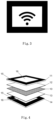
- Fig. 3 shows an example of a design element with a symbol for a Wi-Fi function.
- the Wi-Fi symbol is represented by black print surrounded by a non-printing area, which in turn is framed by black print.
- a white underlay (not shown) provides good contrast and visibility.
- Fig. 4 shows an exploded view of a section of another laminated glass 18 according to the invention, which shows only the partial area on which a design element is arranged.
- the design element 9 with black print area 15 and print-free area 16 corresponds to the design element of Fig. 3 , except that there is no WiFi sign inside.
- the cutout of the laminated glass shows a partial area of the outer pane 14 and a partial area of the inner pane 11, between which partial areas of two lamination layers 12, 13 are shown.
- the two lamination layers 12, 13 are both PVB lamination layers, whereby the lamination layer 13 located between the outer glass and the base is clear and the lamination layer 12 located between the inner glass and the base is tinted.
- the design element 9 was printed image-wise on the partial area of the outer glass and congruently on the partial area of the inner glass, more precisely on the inner side of the outer pane 14 (side 2) and the inner side of the inner pane 11 (side 4). This was done in each case by screen printing with a black ceramic ink.
- An opaque, white PET base 10 is arranged between the partial areas of the two lamination layers 12, 13 such that it underlies the print-free areas of the design element 9.
- the dimensions of the base 10 correspond to the dimensions of the design element 9.
- the thickness of the base 10 is, for example, in the range of 20 to 70 ⁇ m, e.g., approximately 50 ⁇ m.
- the white base provides good contrast and good visibility for the design element.
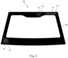
- Fig. 5 shows an oblique view of another laminated glass 18 according to the invention with three design elements 9 (top view of the outer pane).
- the laminated glass has a full-surface black print 15 running around the entire edge area of the laminated glass.
- the three design elements 9 are formed in the full-surface black print and surrounded by it.
- the full-surface black print and the three design elements 9 were printed together in one step on side 2 of the laminated glass using screen printing with black ceramic ink.
- the central area of the laminated glass without black print represents the see-through area of the laminated glass.
- a full-surface black print can be printed, if necessary, that is congruent with the full-surface black print from side 2, but without design elements.
- the dotted borders 17 around the design elements 9 are not actual dotted borders of the laminated glass, but are intended to indicate the position and dimensions of the respective underlying white underlay, which is located within the laminated glass and is not visible in this illustration.
Landscapes
- Joining Of Glass To Other Materials (AREA)
- Laminated Bodies (AREA)
Description
- Die Erfindung betrifft ein Verbundglas, das ein Designelement aufweist, und ein Verfahren zur Herstellung dieses Verbundglases. Das Verbundglas ist insbesondere als Fahrzeugscheibe geeignet.
- Der Einsatz von smarten Funktionen wie eine WiFi-Funktion wird in Automobilen immer wichtiger. Um darauf hinzuweisen, dass das Fahrzeug eine solche Funktion besitzt, wird häufig ein Designelement auf eine Scheibe des Fahrzeugs angebracht. Auch andere Informationen, wie z.B. Produktinformationen, werden als Designelement auf Fahrzeugscheiben angebracht.
- Derzeit werden solche Designelemente auf Fahrzeugscheiben durch einen Schwarzdruck gebildet, der druckfreie Bereiche aufweist, wodurch ein Bild durch Schwarzdruck und druckfreie Bereiche gebildet wird. Einfache Scheiben und Verbundgläser, die als Fahrzeugscheiben eingesetzt werden, sind gemäß ihrer Funktion transparent. Entsprechend sind in Verbundgläser eingesetzte Laminierschichten transparent bzw. klar. Daher weisen die Designelemente nur einen geringen Kontrast auf. Die Folge ist eine schlechte Sichtbarkeit des Designelements. Dies bedeutet, dass das Designelement nur bei einem geringen Abstand sehr nahe an dem Verbundglas überhaupt erkennbar ist.
- Es sind Verfahren zur Erhöhung des Kontrastes bekannt, bei denen ein zusätzlicher Siebdruck in einer hellen Farbe verwendet wird. Dies erfordert jedoch einen zusätzlichen Prozessschritt und eine zusätzliche Siebdruckanlage und ist komplizierter, kostenintensiv und erfordert signifikante Änderungen bei vorhandenen Produktionslinien. Auch die Genauigkeit der erstellten verschiedenen Drucke kann ein Problem darstellen.
- Aus der
DE 10 2008 017 895 A1 ist eine Verbundglasscheibe bekannt, bei der an der Innenseite einer Außenscheibe mittels eines Siebdruckverfahrens ein Negativ des späteren sichtbaren Zeichens angebracht wird. Im Bereich des Zeichens wird eine Sichtfolie mit der Haftschicht, die die beiden Scheiben der Verbundglasscheibe zusammenhält, verklebt. So soll eine hohe Qualität des Zeichens erreicht werden. Ein Nachteil dieser Lösung ist, dass es in dem Bereich der Sichtfolie zwischen der Sichtfolie und der Scheibe zu Lufteinschlüssen beim Laminieren kommen kann, die die Darstellung des Zeichens beeinträchtigen. - Der Erfindung liegt daher die Aufgabe zu Grunde, ein Verbundglas mit einem Designelement bereitzustellen, bei dem das Designelement kontrastreicher ist und damit eine verbesserte Sichtbarkeit zeigt. Zusätzlich soll das ein Designelement aufweisende Verbundglas auf einfache und kostengünstige Weise hergestellt werden können.
- Diese Aufgabe konnte insbesondere durch Einbau einer opaken, nicht-schwarzen Unterlage in den Folienverbund des Verbundglases zur Unterlegung des auf einer Scheibenseite befindlichen Designelements gelöst werden.
- Die Aufgabe der vorliegenden Erfindung wird daher erfindungsgemäß durch ein Verbundglas gemäß Anspruch 1 und ein Verfahren zur Herstellung des Verbundglases gemäß Anspruch 12 gelöst. Bevorzugte Ausführungen gehen aus den Unteransprüchen hervor.
- Durch den Einbau der opaken, nicht-schwarzen Unterlage ist es möglich, die druckfreien Bereiche des Designelements mit einem starken Kontrast gegenüber den Schwarzdruckbereichen hervorzuheben, wodurch eine deutlich verbesserte Sichtbarkeit des Designelements erreicht wird. Durch Auswahl der Farbe der Unterlage kann die Stärke des Kontrasts und das Aussehen des Designelements den Wünschen entsprechend eingestellt werden. Ferner ist hierfür eine relativ einfach auszuführende und kostengünstige Verfahrensmaßnahme notwendig, die keine große Änderung in den vorhandenen Produktionslinien erfordert.
- Dementsprechend betrifft die vorliegende Erfindung ein Verbundglas 18, umfassend eine Außenscheibe 5, eine Innenscheibe 6, mindestens zwei Laminierschichten 7,8, die zwischen der Außenscheibe 5 und der Innenscheibe 6 angeordnet sind, und mindestens ein Designelement 9, wobei das Designelement 9 auf einem Teilbereich einer Scheibenseite der Außenscheibe 5 oder der Innenscheibe 6 aus einem bildmäßigen Schwarzdruck 15 mit einem oder mehreren druckfreien Bereichen 16 gebildet ist und zwischen den beiden Laminierschichten 7, 8 eine opake, nicht-schwarze Unterlage 10 angeordnet ist, die dem oder den druckfreien Bereichen 16 des Designelements 9 unterlegt ist.
- Die Erfindung wird im Folgenden und in den beigefügten Figuren erläutert. In diesen zeigt:
- Fig. 1
- ein Beispiel für ein Designelement,
- Fig. 2
- eine Explosionsdarstellung eines erfindungsgemäßen Verbundglases,
- Fig. 3
- ein Beispiel für ein weiteres Designelement für eine WiFi-Funktion,
- Fig. 4
- eine Explosionsdarstellung eines Ausschnitts eines weiteren erfindungsgemäßen Verbundglases, der den Teilbereich zeigt, auf dem das Designelement angeordnet ist,
- Fig. 5
- eine Schrägansicht eines erfindungsgemäßen Verbundglases mit drei Designelementen.
- Das Verbundglas umfasst eine Außenscheibe und eine Innenscheibe, die durch mindestens zwei dazwischenliegende Laminierfolien zu einem festen Verbund laminiert werden.
- Mit der Innenscheibe wird im Sinne der Erfindung die Glasscheibe bezeichnet, die beim Einbau, z.B. in ein Fahrzeug oder ein Bauwerk, als die dem Innenraum, z.B. einem Fahrzeuginnenraum oder einem Wohnraum, zugewandte Scheibe des Verbundglases vorgesehen ist. Mit der Außenscheibe wird die Glasscheibe bezeichnet, die beim Einbau, z.B. in ein Fahrzeug oder ein Bauwerk, als die der äußeren Umgebung zugewandte Scheibe vorgesehen ist.
- Das Verbundglas, insbesondere für eine Fahrzeugscheibe, kann ein flaches oder gebogenes Verbundglas sein. Bei einem flachen Verbundglas sind die Innenscheibe und die Außenscheibe flach. Bei einem gebogenen Verbundglas sind die Innenscheibe und die Außenscheibe gebogen. Gebogenes Verbundglas wird z.B. als Frontscheibe oder Heckscheibe in Fahrzeugen verwendet.
- Die Innenscheibe und die Außenscheibe können aus dem gleichen Material oder aus verschiedenem Material sein. Die Innenscheibe und die Außenscheibe können aus anorganischem Glas und/oder organischem Glas (Polymere) sein, wobei anorganisches Glas bevorzugt ist. In einer bevorzugten Ausführungsform enthält die Innenscheibe und/oder die Außenscheibe Flachglas, Quarzglas, Borosilikatglas, Kalk-Natron-Glas, Alkalialuminosilikatglas, Polycarbonat und/oder Polymethacrylat. Die Innenscheibe und die Außenscheibe sind bevorzugt aus Kalk-Natron-Glas.
- Die Innenscheibe und die Außenscheibe können die gleiche Dicke oder unterschiedliche Dicken aufweisen. Bevorzugt weisen die Innenscheibe und die Außenscheibe unabhängig voneinander eine Dicke im Bereich von 0,4 bis 5,0 mm, z.B. 0,4 bis 3,9 mm, bevorzugter 1,6 bis 2,5 mm, auf. Aus mechanischen Gründen ist die Außenscheibe bevorzugt dicker oder gleich dick wie die Innenscheibe.
- Die Innenscheibe und die Außenscheibe können klar oder getönt sein. Getönte Scheiben sind bevorzugt grau oder dunkelgrau. Die Innenscheibe und die Außenscheibe sind bevorzugt klar. Getönte Scheiben sind bevorzugt grün.
- Die Innenscheibe und/oder die Außenscheibe können weitere geeignete, an sich bekannte Beschichtungen aufweisen, z.B. Antihaftbeschichtungen, getönte Beschichtungen, infrarotreflektierende Beschichtungen, z.B. in Form einer Metallbeschichtung, Antikratzbeschichtungen oder Low-E-Beschichtungen. Ein Beispiel für beschichtetes Glas ist Low-E-Glas (Low-Emissivity-Glas).
- In einer bevorzugten Ausführungsform sind beide Gläser klar und die innere Seite der Außenscheibe (Seite 2) oder bevorzugt die äußere Seite der Innenscheibe (Seite 3) ist mit einer infrarotreflektierenden Beschichtung, insbesondere einer Metallbeschichtung, versehen. In einer alternativen Ausführungsform sind beide Gläser klar und im Verbund ist eine infrarotreflektierende Folie, insbesondere eine metallbeschichtete Folie, vorgesehen.
- Das Verbundglas umfasst ferner zwischen Innenscheibe und Außenscheibe zwei oder mehr Laminierschichten. Die mindestens zwei Laminierschichten können gleich oder verschieden sein. Die Laminierschichten erstrecken sich jeweils im Wesentlichen über die gesamte Fläche des Verbundglases. Die folgenden Angaben beziehen sich unabhängig voneinander auf alle diese mindestens zwei Laminierschichten, sofern nicht anders angegeben.
- Die Laminierschicht ist insbesondere eine polymere Laminierschicht. Vorzugsweise enthält die Laminierschicht ein thermoplastisches Polymer. In der Regel werden als Ausgangsmaterial zur Bildung der Laminierschichten entsprechende handelsübliche Laminierfolien eingesetzt. Sie dienen zur Verklebung bzw. Laminierung der Komponenten der Fahrzeugscheibe, um den haftenden Glasverbund zu erhalten.
- Die Laminierschicht kann z.B. Polyvinylbutyral (PVB), Ethylenvinylacetat, Polyurethan, Polypropylen, Polyacrylat, Polyethylen, Polycarbonat, Polymethylmetacrylat, Polyvinylchlorid, Polyacetatharz, Gießharz, Acrylat, fluoriniertes Ethylen-Propylen, Polyvinylfluorid und/oder Ethylen-Tetrafluorethylen und/oder ein Gemisch und/oder ein Copolymer davon enthalten. Vorzugsweise enthält die Laminierschicht Polyvinylbutyral (PVB), Ethylenvinylacetat, Polyurethan, und/oder Gemische davon und/oder Copolymere davon, wobei PVB-Laminierschichten besonders bevorzugt sind.
- Die Laminierschichten, bevorzugt PVB-Laminierschichten, weisen jeweils bevorzugt eine Dicke von 0,04 bis 1,5 mm, bevorzugter 0,1 bis 1,2 mm, noch bevorzugter von 0,3 bis 0,9 mm, auf.
- Insbesondere ist die zwischen dem Designelement und der Unterlage angeordnete Laminierschicht transparent, wobei sie bevorzugt klar, d.h. farblos, oder getönt sein kann. Getönte Laminierschichten sind bevorzugt grau, blau oder grün getönt. Die Laminierschicht zwischen dem Designelement und der Unterlage ist bevorzugt klar, da auf diese Weise der durch die Unterlage erreichte Kontrast des Designelements am besten zur Geltung kommt. Es ist aber auch der Einsatz einer getönten Laminierschicht möglich, wenn für das Designelement ein spezieller optischer Effekt gewünscht ist.
- Die Laminierschichten, die nicht zwischen dem Designelement und der Unterlage angeordnet sind, sind ebenfalls vorzugsweise transparent, wobei sie klar oder getönt sein können. Getönte Laminierschichten sind bevorzugt grau, blau oder grün getönt.
- Das Verbundglas weist mindestens ein Designelement auf. Das Designelement ist auf einem Teilbereich einer Scheibenseite der Außenscheibe oder der Innenscheibe aus einem bildmäßigen Schwarzdruck mit einem oder mehreren druckfreien Bereichen gebildet.
- Bei der Scheibenseite der Außenscheibe oder der Innenscheibe kann es sich um eine oder mehrere von der äußeren Seite der Außenscheibe, hier auch als Seite 1 bezeichnet, der inneren Seite der Außenscheibe, hier auch als Seite 2 bezeichnet, der äußeren Seite der Innenscheibe, hier auch als Seite 3 bezeichnet, und der inneren Seite der Innenscheibe, hier auch als Seite 4 bezeichnet, handeln.
- In bevorzugten Ausführungsformen ist die Scheibenseite, auf die das Designelement aufgedruckt ist, die Seite 2 und/oder die Seite 4, wobei die Scheibenseite, auf die das Designelement aufgedruckt ist, besonders bevorzugt die Seite 2 ist.
- Das Designelement ist aus einem bildmäßigen Schwarzdruck mit einem oder mehreren druckfreien Bereichen gebildet. Ein bildmäßiger Schwarzdruck mit einem oder mehreren druckfreien Bereichen bedeutet, dass ein Bild aus der Kombination von einem oder mehreren Bereichen, die einen schwarzen Druck aufweisen, und einem oder mehreren druckfreien Bereichen erzeugt wird. Es handelt sich dementsprechend um einen einfarbigen Druck, bei dem das Bild des Designelements durch schwarz gefärbte Bereiche und frei gelassene Bereiche dargestellt wird. Solche Designelemente, die aus einem bildmäßigen Schwarzdruck mit einem oder mehreren druckfreien Bereichen gebildet werden, sind in der Technik bekannt.
- Die bildmäßige Information kann sich dabei aus den druckfreien Bereichen oder den schwarz gefärbten Bereichen oder einer Kombination davon ergeben. Bei dem bildmäßigen Schwarzdruck kann es sich z.B. um einen Stempeldruck, wie einem Produktstempel, oder um einen Negativdruck handeln, wobei es sich bevorzugt um einen Negativdruck handelt. Der Negativdruck ist dabei bevorzugt im Schwarzdruck ausgespart.
- Bei der durch das Designelement gebildeten Darstellung kann es sich z.B. um Schriftzeichen, Symbole, Hinweiszeichen, graphische Muster, ein Logo oder Kombinationen davon handeln. Das Designelement kann sich als dekoratives Designelement eignen.
- Für den bildmäßigen Schwarzdruck kann eine beliebige schwarze Farbe verwendet werden. Beispiele sind ein Schwarzdruck aus schwarzer Keramikfarbe oder anderen schwarzen Druckfarben, wobei schwarze Keramikfarbe, die auch als schwarze Emailfarbe bezeichnet wird, bevorzugt ist. Bei dem bildmäßigen Schwarzdruck handelt es sich bevorzugt um einen Siebdruck mit einer schwarzen Keramikfarbe. Dies ist das in der Technik übliche Verfahren.
- Das Verbundglas weist seiner Funktion entsprechend einen Durchsichtsbereich auf, in dem das Verbundglas keinen Schwarzdruck aufweist. In der Regel macht der Durchsichtsbereich des Verbundglases mindestens 30%, bevorzugt mindestens 50% der Fläche des Verbundglases aus, z.B. bei Dachscheiben, kann aber auch mit mindestens 70% oder mindestens 80% deutlich größer sein, z.B. bei Windschutzscheiben oder Heckscheiben. Es versteht sich, dass das Designelement nur auf einem Teilbereich des Verbundglases vorliegt und dieser Teilbereich außerhalb des Durchsichtsbereichs liegt.
- Die Größe des mindestens einen Designelements ist ansonsten nicht grundsätzlich beschränkt. Es können ein oder mehrere Designelemente vorhanden sein.
- Das Designelement kann an einer beliebigen Position des Verbundglases angeordnet sein. Vorzugsweise befindet es sich im Randbereich des Verbundglases. Im Allgemeinen ist es aber bevorzugt, dass das Designelement einen Abstand von mindestens 10 mm vom Rand des Verbundglases aufweist.
- Das erfindungsgemäße Verbundglas umfasst ferner eine opake, nicht-schwarze Unterlage, die zwischen den beiden Laminierschichten so angeordnet ist, dass sie dem oder den druckfreien Bereichen des Designelements unterlegt ist. Der Ausdruck "unterlegt" bedeutet hier, dass die Unterlage sich, bezogen auf die beabsichtigte Blickrichtung auf das Designelement, hinter dem oder den druckfreien Bereichen des Designelements befindet, wobei die beabsichtigte Blickrichtung bei einem Designelement auf einer Scheibenseite der Außenscheibe von außen nach innen ist und bei einem Designelement auf einer Scheibenseite der Innenseite von innen nach außen ist. Auf diese Weise wird die Unterlage bei der beabsichtigten Blickrichtung durch die druckfreien Bereiche hindurch sichtbar und bewirkt einen höheren Kontrast.
- Während die Laminierschichten allgemein ganzflächig im gesamten Bereich des Verbundglases vorliegen, befindet sich die Unterlage nur in einem Teilbereich des Verbundglases.
- Die Größe der Unterlage kann gleich der Größe des Designelements sein. Die Größe der Unterlage kann aber auch kleiner als die Größe des Designelements sein, sofern alle druckfreien Bereiche des Designelements mit der Unterlage unterlegt werden können. Die Unterlage ist bevorzugt zumindest etwas größer als es zur Unterlegung der druckfreien Bereiche des Designelements erforderlich ist. Dies kann zweckmäßig sein, damit etwaige Ungenauigkeiten in der Positionierung nicht unmittelbar dazu führen, dass ein Teil der druckfreien Bereiche von der Unterlage nicht unterlegt ist. Eine etwas größere Abmessung der Unterlage kann auch wegen einer besseren Handhabbarkeit des die Unterlage bildenden Folienstücks zweckmäßig sein. Die Unterlage kann gegebenenfalls auch größer sein als das Designelement, z.B. wenn das Designelement von einem vollflächigen Schwarzdruck umgeben ist wie nachstehend beschrieben. Die Unterlage sollte aber so positioniert und dimensioniert sein, dass sie nicht in den Durchsichtsbereich des Verbundglases hineinragt.
- Die Größe der Unterlage hängt somit im Wesentlichen von der Größe und Art des Designelements ab, die Fläche der Unterlage kann z.B. nicht mehr als 70%, bevorzugt nicht mehr als 50%, bevorzugter nicht mehr als 20% und insbesondere nicht mehr als 5%, bevorzugt nicht mehr als 2%, der Fläche des Verbundglases betragen. Dies hängt auch von der Verwendung des Verbundglases ab. So sind z.B. bei einer Dachscheibe relativ große Designelemente denkbar, während bei Heck- oder Windschutzscheiben eher kleinere Designelemente bevorzugt sind. Die Anzahl der Unterlagen entspricht im allgemeinen der Anzahl der vorhandenen Designelemente.
- Die Geometrie der Unterlage ist beliebig. In der Praxis sind z.B. rechteckige Unterlagen zweckmäßig. Die Geometrie kann aber auch an die Geometrie des Designelements angepasst werden und z.B. kreisförmig oder unregelmäßig sein.
- Bei der Unterlage handelt es sich um ein Flächenmaterial. Da die Unterlage nur in einem Teilbereich des Verbundglases angeordnet ist, ergeben sich Dickenänderungen im Verbundglas. Um zu große Dickenänderungen im Verbundglas zu vermeiden, sollte die Unterlage nicht zu dick sein. Andererseits können sich Schwierigkeiten bei der Handhabung des die Unterlage bildenden Folienstücks ergeben, wenn die Unterlage zu dünn ist.
- Im allgemeinen ist es daher zweckmäßig, wenn die Unterlage eine Dicke im Bereich von 1 bis 120 µm, bevorzugt 10 bis 100 µm und bevorzugter 20 bis 70 µm aufweist.
- Die Unterlage ist opak und weist eine nicht-schwarze Farbe auf. Die Farbe der Unterlage kann nach Bedarf gewählt werden. Alle nicht-schwarze Farben sind denkbar. Vorzugsweise wird eine Farbe gewählt, die einen großen Kontrast zum Schwarzdruck aufweist. Die opake Unterlage ist besonders bevorzugt weiß. Bei einer weißen Unterlage ergibt sich der stärkste Kontrast, wodurch die Sichtbarkeit des Designelements optimiert wird.
- Bei der opaken Unterlage handelt es bevorzugt um eine Kunststoffunterlage, insbesondere eine flächige Kunststoffunterlage. Diese wird gewöhnlich aus einem entsprechenden Folienstück gebildet. Die Kunststoffunterlage enthält in der Regel farbgebende Mittel, z.B. Pigmente, um Opazität und Farbigkeit zu erlangen.
- Die opake Unterlage kann z.B. aus einem Polymer, insbesondere einem thermoplastischen Polymer, wie z.B. Polyethylenterephthalat (PET), gebildet sein, das den Hauptbestandteil oder den einzigen Bestandteil der Unterlagenmatrix bildet. Neben dem genannten Polymer kann die Unterlage weitere Polymere und Additive enthalten, wie sie auf dem Gebiet üblich sind. Beispiele für Additive sind farbgebende Mittel, wie z.B. Pigmente, UV-Schutzmittel, Füllstoffe und dergleichen. Wie vorstehend ausgeführt enthält die Unterlage in der Regel farbgebende Mittel, z.B. Pigmente, zur Erlangung von Opazität und Farbigkeit.
- Die opake, nicht-schwarze Unterlage ist besonders bevorzugt aus PET gebildet, wobei eine weiße PET-Unterlage besonders bevorzugt ist. PET-Unterlagen sind besonders bevorzugt, da dünne PET-Folien im Bereich der gewünschten Unterlagendicke zur Verfügung stehen und PET eine gute Verträglichkeit mit den Laminierschichten, insbesondere den PVB-Laminierschichten, aufweist.
- Das Verbundglas kann auch einen vollflächig ausgebildeten Schwarzdruck aufweisen, der bevorzugt am Seitenrand des Verbundglases ausgebildet ist und dabei vorzugsweise den ganzen Seitenrand des Verbundglases umläuft. Verbundgläser, insbesondere Verbundgläser für Fahrzeugscheiben, werden häufig mit einem vollflächigen Schwarzdruck am Seitenrand versehen, um bestimmte Elemente optisch zu verdecken, die für den Einbau in ein Fahrzeug oder Bauwerk erforderlich sind, wie z.B. Klebverbindungen.
- Der vollflächige Schwarzdruck kann mit den gleichen Verfahren und den gleichen Druckfarben durchgeführt werden, die hier auch für den bildmäßigen Schwarzdruck beschrieben sind, worauf verwiesen wird. Zur Bildung des vollflächigen Schwarzdrucks ist ebenfalls ein Siebdruck mit schwarzen Keramikfarben üblich und bevorzugt.
- In einer bevorzugten Ausführungsform ist das Designelement von einem vollflächig ausgebildeten Schwarzdruck umgeben, wobei der vollflächig ausgebildete Schwarzdruck bevorzugt in einem Randbereich des Verbundglases ausgebildet ist, wobei der vollflächig ausgebildete Schwarzdruck besonders bevorzugt den ganzen Randbereich des Verbundglases umläuft. Auch in diesem Fall ist es allgemein bevorzugt, dass das Designelement einen Abstand von mindestens 10 mm vom Rand des Verbundglases aufweist. Wenn das Designelement in einem vollflächig ausgebildeten Schwarzdruck enthalten ist, ist es gewöhnlich zweckmäßig, Designelement und vollflächigen Schwarzdruck in einem Schritt auf dieselbe Scheibenseite aufzudrucken, wobei die Scheibenseite bevorzugt Seite 2 und/oder Seite 4, bevorzugter Seite 2, ist.
- In einer bevorzugten Ausführungsform weist die Scheibe, die der das Designelement aufweisende Scheibe gegenübersteht, in deckungsgleicher Position zum
- Designelement das gleiche Designelement, ein anderes Designelement oder einen vollflächigen Schwarzdruck auf. Dies ist vorteilhaft, um den Blick auf die opake Unterlage von der Blickrichtung zu verdecken, die für das Designelement nicht die beabsichtigte Blickrichtung ist. Im Fall eines gleichen oder unterschiedlichen Designelements auf der gegenüberstehenden Scheibe erreicht man zusätzlich, dass sowohl von innen als auch von außen auf das Designelement geblickt werden kann.
- Das Verbundglas kann ferner gegebenenfalls eine oder mehrere zusätzliche Funktionsschichten, insbesondere polymere Funktionsschichten, zwischen der Außenscheibe und der Innenscheibe umfassen. Solche zusätzlichen Funktionsschichten sind auf dem Gebiet bekannt. In der Regel werden als Ausgangsmaterial zur Bildung der Funktionsschichten entsprechende handelsübliche Funktionsfolien eingesetzt.
- Beispiele für optionale zusätzliche Funktionsschichten sind Akustikschichten oder IR-reflektierende Schichten. IR steht wie üblich als Abkürzung für Infrarot. Sofern zusätzliche Funktionsschichten enthalten sind, sind sie bevorzugt zwischen zwei Laminierschichten angeordnet. Die Funktionsschichten können z.B. jeweils eine Dicke im Bereich von 0,04 bis 1,5 mm, bevorzugt 0,1 bis 1,5 mm, bevorzugter von 0,3 bis 0,9 mm, aufweisen.
- Akustikschichten sind z.B. aus mehreren, z.B. drei, PVB-Schichten aufgebaut, wobei in der Mitte eine weichere PVB-Schicht enthalten ist. Da die Akustikschichten auch als Laminierschichten geeignet sind, können sie eine Doppelfunktion ausüben.
- IR-reflektierende Schichten sind z.B. aus einer polymeren Trägerschicht und einer darauf befindlichen IR-reflektierenden Beschichtung gebildet. Die polymere Trägerschicht kann z.B. aus Polyester, Polycarbonat, Celluloseacetat, Acrylat oder Polyvinylchlorid gebildet sein. Die IR-reflektierende Beschichtung kann grundsätzlich unterschiedlich ausgebildet sein und umfasst bevorzugt mindestens eine Silberschicht. Allgemein üblich sind Mehrfachschichten mit einer oder mehreren Silberschichten als eigentlicher Funktionsschicht, die zwischen metallischen und/oder dielektrischen Schichten eingebettet sind. Wie vorstehend ausgeführt, sind IR-reflektierende Beschichtungen zusätzlich oder bevorzugt alternativ direkt auf der Innenscheibe oder Außenscheibe denkbar, wofür ebenfalls mindestens eine Silberschicht oder die genannten Mehrfachschichten eingesetzt werden können.
- Im Allgemeinen ist es bevorzugt, dass zwischen der Unterlage und der Scheibe, die das Designelement trägt, nur eine Laminierschicht vorhanden ist. Gegebenenfalls können aber mehr als eine Laminierschicht und/oder eine oder mehrere Funktionsschichten zwischen Unterlage und der Scheibe, die das Designelement trägt, angeordnet werden, sofern es sich bei diesen Schichten jeweils um transparente Schichten handelt. Dies ist aber weniger bevorzugt.
- Das erfindungsgemäße Verbundglas eignet sich insbesondere als Fahrzeugscheibe oder als Bauverglasung. Das Verbundglas ist besonders bevorzugt eine Fahrzeugscheibe, insbesondere eine Automobilscheibe, z.B. eine Dachscheibe, eine Seitenscheibe, eine Frontscheibe oder eine Heckscheibe.
- Die Erfindung betrifft ferner ein Verfahren zur Herstellung eines erfindungsgemäßen Verbundglases wie vorstehend beschrieben, wobei das Verfahren folgende Schritte umfasst:
- a) bildmäßiges Aufdrucken einer schwarzen Farbe auf einen Teilbereich einer Seite einer Scheibe, wodurch ein Designelement 9 aus einem Schwarzdruck mit einem oder mehreren druckfreien Bereichen gebildet wird,
- b) Bereitstellen einer Anordnung, die in dieser Reihenfolge eine Außenscheibe 5, eine erste Laminierfolie 8, eine zweite Laminierfolie 7 und eine Innenscheibe 6 umfasst, wobei für die Außenscheibe 5 oder die Innenscheibe 6 die in Schritt a) erhaltene Scheibe mit dem Designelement 9 verwendet wird und wobei ein opakes, nicht-schwarzes Folienstück so zwischen die beiden Laminierfolien 7, 8 positioniert wird, dass sie im fertigen Verbundglas 18 dem oder den druckfreien Bereichen 16 des Designelements 9 als Unterlage 10 unterlegt ist, und
- c) Wärmebehandlung der in Schritt b) erhaltenen Anordnung zum Laminieren der Anordnung unter Bildung des Verbundglases.
- Alle vorstehenden Angaben für das erfindungsgemäße Verbundglas gelten entsprechend auch für das erfindungsgemäße Verfahren.
- Das bildmäßige Aufdrucken der schwarzen Farbe kann z.B. mittels Siebdruck, Tintenstrahldruck oder Lasertransferdruck durchgeführt werden, wobei Siebdruck bevorzugt ist. Als schwarze Farbe eignen sich alle üblichen Farben, z.B. Keramikfarbe oder andere Druckfarben, wobei Keramikfarbe bevorzugt ist. Bevorzugt erfolgt der bildmäßige Aufdruck durch Siebdruck mit schwarzer Keramikfarbe. Wenn das Designelement von einem vollflächigen Schwarzdruck umgeben ist, der vorzugsweise den Seitenrand des Verbundglases umläuft, können der bildmäßige Aufdruck und der vollflächige Schwarzdruck in einem Schritt gemeinsam aufgedruckt werden, z.B. durch Siebdruck.
- Je nach eingesetzter Druckfarbe für das Designelement ist gegebenenfalls auch eine Wärmebehandlung zum Einbrennen der Druckfarbe notwendig, insbesondere, wenn Keramikfarben bzw. Emailfarben eingesetzt werden. Die Wärmebehandlung zum Einbrennen kann z.B. bei Temperaturen im Bereich von 400 °C bis 700 °C, bevorzugt 550 °C bis 650 °C, durchgeführt werden, insbesondere wenn das Aufdrucken mit einer Keramikfarbe erfolgt. Die erforderliche Wärmbehandlung oder das Einbrennen des Schwarzdrucks wird gewöhnlich nach dem Druck und vor dem Anordnen und Laminieren des Verbundglases durchgeführt.
- Das opake, nicht-schwarze Folienstück wird in Schritt b) so zwischen die beiden Laminierfolien positioniert, dass es im fertigen Verbundglas dem oder den druckfreien Bereichen des Designelements als Unterlage unterlegt ist.
- In einer bevorzugten Ausführungsform wird das opake Folienstück in Schritt b) nach der Positionierung an einer der beiden Laminierfolien vorfixiert. Dies erfolgt vorzugsweise durch Wärmebehandlung, z.B. mithilfe eines Heißluftföns. Die Positionierung und gegebenenfalls Vorfixierung des opaken Folienstücks auf einer Laminierfolie kann erfolgen, bevor oder nachdem die Laminierfolie auf die zu bildende Anordnung angeordnet wurde.
- Für das opake Folienstück gelten die vorhergehenden Angaben zur Unterlage in gleicher Weise, insbesondere hinsichtlich der Abmessungen, der Dicke und der Art, so dass darauf verwiesen wird. Dementsprechend ist das opake Folienstück bevorzugt ein PET-Folienstück, insbesondere ein weißes PET-Folienstück.
- Die Laminierung der Anordnung erfolgt mithilfe einer Wärmebehandlung, was z.B. unter Atmosphärendruck, Unterdruck oder Überdruck durchgeführt werden kann. Die Laminierung der Anordnung kann z.B. an Luft oder unter Schutzgasatmosphäre erfolgen. Der Fachmann ist mit den geeigneten Verfahren und Bedingungen gut vertraut.
- Die Wärmebehandlung der in Schritt b) erhaltenen Anordnung zum Laminieren der Anordnung erfolgt nach den bekannten Standardverfahren, z.B. bei Temperaturen von nicht mehr als 200 °C, z.B. im Bereich von 80 bis 150 °C.
- Die Erfindung wird nachfolgend anhand von nicht einschränkenden Ausführungsbeispielen unter Bezug auf die beigefügten Zeichnungen weiter erläutert. Die Zeichnungen sind schematisch und nicht maßstabsgetreu.
-
Fig. 1 zeigt ein Beispiel für ein Designelement 9, bei dem die druckfreien Bereiche 16 in einem Schwarzdruck 15 Schriftzüge und Symbole darstellen. Das Designelement ist als Negativdruck gebildet. Durch eine unterlegte weiße Unterlage (nicht gezeigt) ergibt sich ein guter Kontrast und eine gute Sichtbarkeit. -
Fig. 2 zeigt eine Explosionsdarstellung eines erfindungsgemäßen Verbundglases 18, das ein Designelement 9 gemäßFig. 1 aufweist. Das Verbundglas weist eine Außenscheibe 5 und eine Innenscheibe 6 auf, zwischen denen zwei Laminierschichten 7,8 angeordnet sind. Die beiden Laminierschichten 7, 8 sind beide klare PVB-Laminierschichten z.B. mit einer Dicke im Bereich von etwa 0,3 bis 0,9 mm. Das Designelement 9 wurde auf einen Teilbereich der inneren Seite 2 der Außenscheibe 5 (Seite 2) bildmäßig aufgedruckt. Dies erfolgte durch Siebdruck mit einer schwarzen Keramikfarbe. Eine opake, weiße PET-Unterlage 10 ist so zwischen den beiden Laminierschichten 7, 8 angeordnet, dass sie den druckfreien Bereichen des Designelements 9 unterlegt ist. Die Abmessungen der Unterlage sind kleiner als die Abmessungen des Designelements 9, aber etwas größer als es für die Unterlegung der druckfreien Bereiche des Designelements 9 erforderlich wäre. Die Abmessung des Designelements kann z.B. etwa 200 x 300 mm betragen, es sind aber genauso gut kleinere oder größere Abmessungen möglich. Die Dicke der Unterlage liegt z.B. im Bereich von 20 bis 70 µm, z.B. etwa 50 µm. Durch die unterlegte weiße Unterlage ergibt sich ein guter Kontrast und eine gute Sichtbarkeit für das Designelement. -
Fig. 3 zeigt ein Beispiel für ein Designelement mit einem Symbol für eine WiFi-Funktion. Das WiFi-Symbol wird durch einen Schwarzdruck dargestellt, der von einem druckfreien Bereich umgeben ist, der wiederum von einem Schwarzdruck umrahmt ist. Durch eine unterlegte weiße Unterlage (nicht gezeigt) ergibt sich ein guter Kontrast und eine gute Sichtbarkeit. -
Fig. 4 zeigt eine Explosionsdarstellung eines Ausschnitts eines weiteren erfindungsgemäßen Verbundglases 18, der nur den Teilbereich zeigt, auf dem ein Designelement angeordnet ist. Das Designelement 9 mit Schwarzdruckbereich 15 und druckfreiem Bereich 16 entspricht dem Designelement vonFig. 3 , außer dass kein WiFi-Zeichen im Inneren vorhanden ist. Der Ausschnitt des Verbundglases zeigt einen Teilbereich der Außenscheibe 14 und einen Teilbereich der Innenscheibe 11, zwischen denen Teilbereiche von zwei Laminierschichten 12, 13 gezeigt sind. Die beiden Laminierschichten 12, 13 sind beide PVB-Laminierschichten, wobei die zwischen Außenglas und Unterlage befindliche Laminierschicht 13 klar ist und die zwischen Innenglas und Unterlage befindliche Laminierschicht 12 getönt ist. Das Designelement 9 wurde auf dem Teilbereich des Außenglases und deckungsgleich auf dem Teilbereich des Innenglases bildmäßig aufgedruckt, genauer auf die innere Seite der Außenscheibe 14 (Seite 2) und die innere Seite der Innenscheibe 11 (Seite 4). Dies erfolgte jeweils durch Siebdruck mit einer schwarzen Keramikfarbe. Eine opake, weiße PET-Unterlage 10 ist so zwischen den Teilbereichen der beiden Laminierschichten 12, 13 angeordnet, dass sie den druckfreien Bereichen des Designelements 9 unterlegt ist. Die Abmessung der Unterlage 10 entspricht der Abmessung des Designelements 9. Die Dicke der Unterlage 10 liegt z.B. im Bereich von 20 bis 70 µm, z.B. etwa 50 µm. Durch die unterlegte weiße Unterlage ergibt sich ein guter Kontrast und eine gute Sichtbarkeit für das Designelement. -
Fig. 5 zeigt eine Schrägansicht eines weiteren erfindungsgemäßen Verbundglases 18 mit drei Designelementen 9 (Draufsicht auf die Außenscheibe). Das Verbundglas weist einen um den ganzen Randbereich des Verbundglases umlaufenden vollflächigen Schwarzdruck 15 auf. Die drei Designelemente 9 sind in dem vollflächigen Schwarzdruck ausgebildet und davon umgeben. Der vollflächige Schwarzdruck und die drei Designelemente 9 wurden zusammen in einem Schritt mittels Siebdruck mit schwarzer Keramikfarbe auf Seite 2 des Verbundglases aufgedruckt. Der zentrale Bereich des Verbundglases ohne Schwarzdruck stellt den Durchsichtsbereich des Verbundglases dar. Auf der Seite 4 des Verbundglases kann gegebenenfalls ein vollflächiger Schwarzdruck deckungsgleich zum vollflächigen Schwarzdruck aus Seite 2, aber ohne Designelemente aufgedruckt sein. Die gepunkteten Umrandungen 17 um die Designelemente 9 sind keine tatsächlichen gepunkteten Umrandungen des Verbundglases, sondern sollen auf die Position und Abmessung der jeweiligen unterlegten weißen Unterlage hinweisen, die sich innerhalb des Verbundglases befindet und bei dieser Darstellung nicht sichtbar sind. -
- 1
- äußere Seite der Außenscheibe (Seite 1)
- 2
- innere Seite der Außenscheibe (Seite 2)
- 3
- äußere Seite der Innenscheibe (Seite 3)
- 4
- innere Seite der Innenscheibe (Seite 4)
- 5
- Außenscheibe
- 6
- Innenscheibe
- 7
- zweite Laminierschicht
- 8
- erste Laminierschicht
- 9
- Designelement
- 10
- opake Unterlage
- 11
- Teilbereich Innenscheibe
- 12
- Teilbereich zweite Laminierschicht
- 13
- Teilbereich erste Laminierschicht
- 14
- Teilbereich Außenscheibe
- 15
- Schwarzdruck
- 16
- druckfreier Bereich
- 17
- Position Unterlage
- 18
- Verbundglas
Claims (15)
- Verbundglas (18), umfassend eine Außenscheibe (5), eine Innenscheibe (6), mindestens zwei Laminierschichten (7,8), die zwischen der Außenscheibe (5) und der Innenscheibe (6) angeordnet sind, und mindestens ein Designelement (9), wobei das Designelement (9) auf einem Teilbereich einer Scheibenseite der Außenscheibe (5) oder der Innenscheibe (6) aus einem bildmäßigen Schwarzdruck (15) mit einem oder mehreren druckfreien Bereichen (16) gebildet ist und nur in einem Teilbereich des Verbundglases (18) zwischen den beiden Laminierschichten (7, 8) eine opake, nicht-schwarze Unterlage (10) angeordnet ist, die dem oder den druckfreien Bereichen (16) des Designelements (9) unterlegt ist und wobei die Laminierschichten (7, 8) ganzflächig im gesamten Bereich des Verbundglases (18) vorliegen.
- Verbundglas nach Anspruch 1, wobei die Unterlage (10) eine Dicke im Bereich von 1 bis 120 µm, bevorzugt 10 bis 100 µm und bevorzugter 20 bis 70 µm aufweist.
- Verbundglas nach Anspruch 1 oder 2, wobei die opake, nicht-schwarze Unterlage (10) eine weiße Farbe aufweist.
- Verbundglas nach irgendeinem der vorhergehenden Ansprüche, wobei die opake, nicht-schwarze Unterlage (10) aus Polyethylenterephthalat (PET) gebildet ist.
- Verbundglas nach irgendeinem der vorhergehenden Ansprüche, wobei die Scheibenseite, auf die das Designelement (9) aufgedruckt ist, die innere Seite (2) der Außenscheibe (5) ist.
- Verbundglas nach irgendeinem der vorhergehenden Ansprüche, wobei die zwischen dem Designelement (9) und der Unterlage (10) befindliche Laminierschicht (8) klar oder getönt, bevorzugt klar, ist.
- Verbundglas nach irgendeinem der vorhergehenden Ansprüche, wobei das Designelement (9) von einem vollflächig ausgebildeten Schwarzdruck umgeben ist, wobei der vollflächig ausgebildete Schwarzdruck bevorzugt in einem Randbereich des Verbundglases ausgebildet ist und bevorzugt den ganzen Randbereich des Verbundglases umläuft.
- Verbundglas nach irgendeinem der vorhergehenden Ansprüche, bei dem die Scheibe, die der das Designelement (9) aufweisende Scheibe gegenübersteht, in deckungsgleicher Position zum Designelement das gleiche Designelement, ein anderes Designelement oder einen vollflächigen Schwarzdruck aufweist.
- Verbundglas nach irgendeinem der vorhergehenden Ansprüche, bei dem die beiden Laminierschichten (7, 8) jeweils eine Polyvinylbutyral (PVB)-Schicht sind und/oder eine oder mehrere zusätzliche Funktionsschichten zwischen der Außenscheibe (5) und der Innenscheibe (6) angeordnet sind.
- Verbundglas nach irgendeinem der vorhergehenden Ansprüche, wobei der Schwarzdruck des Designelements (9) aus einer Keramikfarbe gebildet ist.
- Verbundglas nach irgendeinem der vorhergehenden Ansprüche, das eine Fahrzeugscheibe oder eine Bauverglasung, bevorzugt eine Fahrzeugscheibe, ist.
- Verfahren zur Herstellung eines Verbundglases (18) nach irgendeinem der Ansprüche 1 bis 11, umfassenda) bildmäßiges Aufdrucken einer schwarzen Farbe auf einen Teilbereich einer Seite einer Scheibe, wodurch ein Designelement (9) aus einem Schwarzdruck mit einem oder mehreren druckfreien Bereichen gebildet wird,b) Bereitstellen einer Anordnung, die in dieser Reihenfolge eine Außenscheibe (5), eine erste Laminierfolie (8), eine zweite Laminierfolie (7) und eine Innenscheibe (6) umfasst, wobei für die Außenscheibe (5) oder die Innenscheibe (6) die in Schritt a) erhaltene Scheibe mit dem Designelement (9) verwendet wird und wobei ein opakes, nicht-schwarzes Folienstück so zwischen die beiden Laminierfolien (7, 8) positioniert wird, dass es im fertigen Verbundglas (18) dem oder den druckfreien Bereichen (16) des Designelements (9) als Unterlage (10) unterlegt ist, undc) Wärmebehandlung der in Schritt b) erhaltenen Anordnung zum Laminieren der Anordnung unter Bildung des Verbundglases.
- Verfahren nach Anspruch 12, wobei das bildmäßige Aufdrucken der schwarzen Farbe mittels Siebdruck, Tintenstrahldruck oder Lasertransferdruck durchgeführt wird, wobei Siebdruck bevorzugt ist.
- Verfahren nach Anspruch 12 oder 13, wobei in Schritt b) das opake Folienstück nach der Positionierung an einer Laminierfolie vorfixiert wird, vorzugsweise durch Wärmebehandlung.
- Verfahren nach irgendeinem der Ansprüche Anspruch 12 bis 14, wobei die Positionierung und gegebenenfalls Vorfixierung des opaken Folienstücks auf einer Laminierfolie erfolgt, bevor oder nachdem sie auf die zu bildende Anordnung angeordnet wurde.
Applications Claiming Priority (2)
| Application Number | Priority Date | Filing Date | Title |
|---|---|---|---|
| EP18185732 | 2018-07-26 | ||
| PCT/EP2019/069628 WO2020020806A1 (de) | 2018-07-26 | 2019-07-22 | Dekoratives designelement im schwarzdruck |
Publications (2)
| Publication Number | Publication Date |
|---|---|
| EP3826839A1 EP3826839A1 (de) | 2021-06-02 |
| EP3826839B1 true EP3826839B1 (de) | 2025-05-21 |
Family
ID=63077745
Family Applications (1)
| Application Number | Title | Priority Date | Filing Date |
|---|---|---|---|
| EP19740397.5A Active EP3826839B1 (de) | 2018-07-26 | 2019-07-22 | Dekoratives designelement im schwarzdruck |
Country Status (5)
| Country | Link |
|---|---|
| US (1) | US11331884B2 (de) |
| EP (1) | EP3826839B1 (de) |
| CN (1) | CN110958939B (de) |
| MA (1) | MA53367A (de) |
| WO (1) | WO2020020806A1 (de) |
Families Citing this family (2)
| Publication number | Priority date | Publication date | Assignee | Title |
|---|---|---|---|---|
| US20250050623A1 (en) * | 2021-12-20 | 2025-02-13 | Saint-Gobain Glass France | Windshield with improved impact protection |
| CN114523824B (zh) * | 2022-01-25 | 2024-03-01 | 福耀玻璃工业集团股份有限公司 | 一种局部区域具有美观图案的汽车玻璃及其加工方法 |
Family Cites Families (5)
| Publication number | Priority date | Publication date | Assignee | Title |
|---|---|---|---|---|
| US6824868B2 (en) * | 2002-04-30 | 2004-11-30 | Solutia, Inc. | Digital color-design composite for use in laminated glass |
| US7727634B2 (en) * | 2002-04-30 | 2010-06-01 | Solutia, Inc. | Decorative glass laminate containing an ultraviolet printed image thereon and a method for preparing said decorative glass laminate |
| US20080014414A1 (en) * | 2006-07-13 | 2008-01-17 | Vincent James Yacovone | Windshield Interlayer Having a Gradient Region Having a White Coloration |
| DE102008017895B4 (de) | 2008-04-09 | 2022-12-08 | Dr. Ing. H.C. F. Porsche Aktiengesellschaft | Verbundglasscheibe und Personenkraftwagen |
| FR2985042B1 (fr) | 2011-12-22 | 2014-01-17 | Saint Gobain | Dispositif de visualisation d'une image sur un support feuillete |
-
2019
- 2019-07-22 MA MA053367A patent/MA53367A/fr unknown
- 2019-07-22 EP EP19740397.5A patent/EP3826839B1/de active Active
- 2019-07-22 CN CN201980001715.XA patent/CN110958939B/zh active Active
- 2019-07-22 WO PCT/EP2019/069628 patent/WO2020020806A1/de not_active Ceased
- 2019-07-22 US US16/979,414 patent/US11331884B2/en active Active
Also Published As
| Publication number | Publication date |
|---|---|
| EP3826839A1 (de) | 2021-06-02 |
| WO2020020806A1 (de) | 2020-01-30 |
| MA53367A (fr) | 2021-06-02 |
| CN110958939A (zh) | 2020-04-03 |
| US11331884B2 (en) | 2022-05-17 |
| CN110958939B (zh) | 2023-11-03 |
| US20210078297A1 (en) | 2021-03-18 |
Similar Documents
| Publication | Publication Date | Title |
|---|---|---|
| DE69423466T2 (de) | Verbundglasscheibe mit einem sichtbaren (motiv) muster | |
| EP1363141B1 (de) | Infrarot reflektierendes Material | |
| EP3484705B1 (de) | Verbundscheibe mit einer mehrlagigen verbundschicht und verfahren zu ihrer herstellung | |
| WO2016091435A1 (de) | Verbundglas mit geringer dicke für ein head-up-display (hud) | |
| EP4132782A1 (de) | Mehrlagige gefärbte zwischenschicht mit keilförmigem querschnitt | |
| DE1951616A1 (de) | Blendung verhuetende und Waerme absperrende Glasplatte | |
| EP4285178A1 (de) | Fahrzeugscheibe für head-up-display | |
| WO2020094419A1 (de) | Verbundscheibe für ein head-up-display | |
| DE202015009817U1 (de) | Kunststoff-Fahrzeuganbauteil | |
| DE102011004500A1 (de) | Verfahren zur Herstellung einer bedruckten Fahrzeug-Verbundscheibe | |
| DE202022002921U1 (de) | Verbundscheibe mit Funktionsfolie mit opakem Aufdruck | |
| EP2574454B1 (de) | Fensterscheibe mit einer gedruckten Struktur für ein Kraftfahrzeug | |
| WO2023117576A1 (de) | Windschutzscheibe mit verbessertem aufprallschutz | |
| WO2020020806A1 (de) | Dekoratives designelement im schwarzdruck | |
| WO2023213621A1 (de) | Verbundscheibe für eine projektionsanordnung | |
| WO2023025546A1 (de) | Verfahren zur herstellung einer bereichsweise beschichteten fahrzeugscheibe | |
| DE112019001719T5 (de) | Laminierte verglasung mit einem stufenförmigen funktionsabschnitt | |
| WO2021254910A1 (de) | Verbundscheibe | |
| DE202021104310U1 (de) | Verbundscheibe mit elektrisch steuerbaren optischen Eigenschaften und blau gefärbter Zwischenschicht | |
| DE202024103266U1 (de) | Fahrzeugscheibe zur Darstellung mindestens einer Leuchtfläche in einem Maskierungsbereich | |
| WO2020094324A1 (de) | Verbundscheibe mit einem funktionselement und abdeckdruck | |
| DE102019131305B3 (de) | Verfahren zum Herstellen einer Verbundscheibe eines Kraftfahrzeugs und Verbundscheibe | |
| DE202020101267U1 (de) | Verbesserte Transmissionsoptik durch rasterförmigen Abdeckdruck | |
| DE202016008420U1 (de) | Verbundscheibe | |
| EP3593994A2 (de) | Vorrichtung zum flächigen abstützen einer gekrümmten glasscheibe beim herstellen einer gekrümmten verbundglasscheibe sowie verbundglasscheibe |
Legal Events
| Date | Code | Title | Description |
|---|---|---|---|
| STAA | Information on the status of an ep patent application or granted ep patent |
Free format text: STATUS: UNKNOWN |
|
| STAA | Information on the status of an ep patent application or granted ep patent |
Free format text: STATUS: THE INTERNATIONAL PUBLICATION HAS BEEN MADE |
|
| PUAI | Public reference made under article 153(3) epc to a published international application that has entered the european phase |
Free format text: ORIGINAL CODE: 0009012 |
|
| STAA | Information on the status of an ep patent application or granted ep patent |
Free format text: STATUS: REQUEST FOR EXAMINATION WAS MADE |
|
| 17P | Request for examination filed |
Effective date: 20210108 |
|
| AK | Designated contracting states |
Kind code of ref document: A1 Designated state(s): AL AT BE BG CH CY CZ DE DK EE ES FI FR GB GR HR HU IE IS IT LI LT LU LV MC MK MT NL NO PL PT RO RS SE SI SK SM TR |
|
| DAX | Request for extension of the european patent (deleted) | ||
| RAV | Requested validation state of the european patent: fee paid |
Extension state: MA Effective date: 20210108 |
|
| STAA | Information on the status of an ep patent application or granted ep patent |
Free format text: STATUS: EXAMINATION IS IN PROGRESS |
|
| 17Q | First examination report despatched |
Effective date: 20241007 |
|
| GRAP | Despatch of communication of intention to grant a patent |
Free format text: ORIGINAL CODE: EPIDOSNIGR1 |
|
| STAA | Information on the status of an ep patent application or granted ep patent |
Free format text: STATUS: GRANT OF PATENT IS INTENDED |
|
| INTG | Intention to grant announced |
Effective date: 20250211 |
|
| GRAS | Grant fee paid |
Free format text: ORIGINAL CODE: EPIDOSNIGR3 |
|
| GRAA | (expected) grant |
Free format text: ORIGINAL CODE: 0009210 |
|
| STAA | Information on the status of an ep patent application or granted ep patent |
Free format text: STATUS: THE PATENT HAS BEEN GRANTED |
|
| RAP1 | Party data changed (applicant data changed or rights of an application transferred) |
Owner name: SAINT-GOBAIN SEKURIT FRANCE |
|
| AK | Designated contracting states |
Kind code of ref document: B1 Designated state(s): AL AT BE BG CH CY CZ DE DK EE ES FI FR GB GR HR HU IE IS IT LI LT LU LV MC MK MT NL NO PL PT RO RS SE SI SK SM TR |
|
| REG | Reference to a national code |
Ref country code: GB Ref legal event code: FG4D Free format text: NOT ENGLISH |
|
| REG | Reference to a national code |
Ref country code: CH Ref legal event code: EP |
|
| REG | Reference to a national code |
Ref country code: DE Ref legal event code: R096 Ref document number: 502019013374 Country of ref document: DE |
|
| REG | Reference to a national code |
Ref country code: IE Ref legal event code: FG4D Free format text: LANGUAGE OF EP DOCUMENT: GERMAN |
|
| PGFP | Annual fee paid to national office [announced via postgrant information from national office to epo] |
Ref country code: FR Payment date: 20250610 Year of fee payment: 7 |
|
| REG | Reference to a national code |
Ref country code: NL Ref legal event code: MP Effective date: 20250521 |
|
| PG25 | Lapsed in a contracting state [announced via postgrant information from national office to epo] |
Ref country code: PT Free format text: LAPSE BECAUSE OF FAILURE TO SUBMIT A TRANSLATION OF THE DESCRIPTION OR TO PAY THE FEE WITHIN THE PRESCRIBED TIME-LIMIT Effective date: 20250922 Ref country code: FI Free format text: LAPSE BECAUSE OF FAILURE TO SUBMIT A TRANSLATION OF THE DESCRIPTION OR TO PAY THE FEE WITHIN THE PRESCRIBED TIME-LIMIT Effective date: 20250521 Ref country code: ES Free format text: LAPSE BECAUSE OF FAILURE TO SUBMIT A TRANSLATION OF THE DESCRIPTION OR TO PAY THE FEE WITHIN THE PRESCRIBED TIME-LIMIT Effective date: 20250521 |
|
| PGFP | Annual fee paid to national office [announced via postgrant information from national office to epo] |
Ref country code: DE Payment date: 20250604 Year of fee payment: 7 |
|
| REG | Reference to a national code |
Ref country code: LT Ref legal event code: MG9D |
|
| PG25 | Lapsed in a contracting state [announced via postgrant information from national office to epo] |
Ref country code: NO Free format text: LAPSE BECAUSE OF FAILURE TO SUBMIT A TRANSLATION OF THE DESCRIPTION OR TO PAY THE FEE WITHIN THE PRESCRIBED TIME-LIMIT Effective date: 20250821 Ref country code: GR Free format text: LAPSE BECAUSE OF FAILURE TO SUBMIT A TRANSLATION OF THE DESCRIPTION OR TO PAY THE FEE WITHIN THE PRESCRIBED TIME-LIMIT Effective date: 20250822 |
|
| PG25 | Lapsed in a contracting state [announced via postgrant information from national office to epo] |
Ref country code: PL Free format text: LAPSE BECAUSE OF FAILURE TO SUBMIT A TRANSLATION OF THE DESCRIPTION OR TO PAY THE FEE WITHIN THE PRESCRIBED TIME-LIMIT Effective date: 20250521 Ref country code: NL Free format text: LAPSE BECAUSE OF FAILURE TO SUBMIT A TRANSLATION OF THE DESCRIPTION OR TO PAY THE FEE WITHIN THE PRESCRIBED TIME-LIMIT Effective date: 20250521 |
|
| PG25 | Lapsed in a contracting state [announced via postgrant information from national office to epo] |
Ref country code: BG Free format text: LAPSE BECAUSE OF FAILURE TO SUBMIT A TRANSLATION OF THE DESCRIPTION OR TO PAY THE FEE WITHIN THE PRESCRIBED TIME-LIMIT Effective date: 20250521 |
|
| PG25 | Lapsed in a contracting state [announced via postgrant information from national office to epo] |
Ref country code: HR Free format text: LAPSE BECAUSE OF FAILURE TO SUBMIT A TRANSLATION OF THE DESCRIPTION OR TO PAY THE FEE WITHIN THE PRESCRIBED TIME-LIMIT Effective date: 20250521 |
|
| PG25 | Lapsed in a contracting state [announced via postgrant information from national office to epo] |
Ref country code: RS Free format text: LAPSE BECAUSE OF FAILURE TO SUBMIT A TRANSLATION OF THE DESCRIPTION OR TO PAY THE FEE WITHIN THE PRESCRIBED TIME-LIMIT Effective date: 20250821 |
|
| PG25 | Lapsed in a contracting state [announced via postgrant information from national office to epo] |
Ref country code: IS Free format text: LAPSE BECAUSE OF FAILURE TO SUBMIT A TRANSLATION OF THE DESCRIPTION OR TO PAY THE FEE WITHIN THE PRESCRIBED TIME-LIMIT Effective date: 20250921 |
|
| PG25 | Lapsed in a contracting state [announced via postgrant information from national office to epo] |
Ref country code: LV Free format text: LAPSE BECAUSE OF FAILURE TO SUBMIT A TRANSLATION OF THE DESCRIPTION OR TO PAY THE FEE WITHIN THE PRESCRIBED TIME-LIMIT Effective date: 20250521 |
|
| PG25 | Lapsed in a contracting state [announced via postgrant information from national office to epo] |
Ref country code: DK Free format text: LAPSE BECAUSE OF FAILURE TO SUBMIT A TRANSLATION OF THE DESCRIPTION OR TO PAY THE FEE WITHIN THE PRESCRIBED TIME-LIMIT Effective date: 20250521 Ref country code: SM Free format text: LAPSE BECAUSE OF FAILURE TO SUBMIT A TRANSLATION OF THE DESCRIPTION OR TO PAY THE FEE WITHIN THE PRESCRIBED TIME-LIMIT Effective date: 20250521 |
|
| PG25 | Lapsed in a contracting state [announced via postgrant information from national office to epo] |
Ref country code: CZ Free format text: LAPSE BECAUSE OF FAILURE TO SUBMIT A TRANSLATION OF THE DESCRIPTION OR TO PAY THE FEE WITHIN THE PRESCRIBED TIME-LIMIT Effective date: 20250521 |
|
| PG25 | Lapsed in a contracting state [announced via postgrant information from national office to epo] |
Ref country code: EE Free format text: LAPSE BECAUSE OF FAILURE TO SUBMIT A TRANSLATION OF THE DESCRIPTION OR TO PAY THE FEE WITHIN THE PRESCRIBED TIME-LIMIT Effective date: 20250521 |
|
| PG25 | Lapsed in a contracting state [announced via postgrant information from national office to epo] |
Ref country code: SK Free format text: LAPSE BECAUSE OF FAILURE TO SUBMIT A TRANSLATION OF THE DESCRIPTION OR TO PAY THE FEE WITHIN THE PRESCRIBED TIME-LIMIT Effective date: 20250521 Ref country code: RO Free format text: LAPSE BECAUSE OF FAILURE TO SUBMIT A TRANSLATION OF THE DESCRIPTION OR TO PAY THE FEE WITHIN THE PRESCRIBED TIME-LIMIT Effective date: 20250521 |
|
| PG25 | Lapsed in a contracting state [announced via postgrant information from national office to epo] |
Ref country code: IT Free format text: LAPSE BECAUSE OF FAILURE TO SUBMIT A TRANSLATION OF THE DESCRIPTION OR TO PAY THE FEE WITHIN THE PRESCRIBED TIME-LIMIT Effective date: 20250521 |
|
| REG | Reference to a national code |
Ref country code: CH Ref legal event code: H13 Free format text: ST27 STATUS EVENT CODE: U-0-0-H10-H13 (AS PROVIDED BY THE NATIONAL OFFICE) Effective date: 20260224 Ref country code: DE Ref legal event code: R097 Ref document number: 502019013374 Country of ref document: DE |
|
| PG25 | Lapsed in a contracting state [announced via postgrant information from national office to epo] |
Ref country code: LU Free format text: LAPSE BECAUSE OF NON-PAYMENT OF DUE FEES Effective date: 20250722 |
|
| REG | Reference to a national code |
Ref country code: BE Ref legal event code: MM Effective date: 20250731 |
|
| PLBE | No opposition filed within time limit |
Free format text: ORIGINAL CODE: 0009261 |
|
| STAA | Information on the status of an ep patent application or granted ep patent |
Free format text: STATUS: NO OPPOSITION FILED WITHIN TIME LIMIT |
|
| REG | Reference to a national code |
Ref country code: CH Ref legal event code: L10 Free format text: ST27 STATUS EVENT CODE: U-0-0-L10-L00 (AS PROVIDED BY THE NATIONAL OFFICE) Effective date: 20260402 |
|
| PG25 | Lapsed in a contracting state [announced via postgrant information from national office to epo] |
Ref country code: BE Free format text: LAPSE BECAUSE OF NON-PAYMENT OF DUE FEES Effective date: 20250731 |
|
| VS25 | Lapsed in a validation state [announced via postgrant information from nat. office to epo] |
Ref country code: MA Free format text: LAPSE BECAUSE OF FAILURE TO SUBMIT A TRANSLATION OF THE DESCRIPTION OR TO PAY THE FEE WITHIN THE PRESCRIBED TIME-LIMIT; INVALID AB INITIO Effective date: 20190722 |
|
| PG25 | Lapsed in a contracting state [announced via postgrant information from national office to epo] |
Ref country code: CH Free format text: LAPSE BECAUSE OF NON-PAYMENT OF DUE FEES Effective date: 20250731 |
|
| 26N | No opposition filed |
Effective date: 20260224 |
|
| GBPC | Gb: european patent ceased through non-payment of renewal fee |
Effective date: 20250821 |