EP3826232B1 - Communication system with immersion counter - Google Patents
Communication system with immersion counter Download PDFInfo
- Publication number
- EP3826232B1 EP3826232B1 EP20207947.1A EP20207947A EP3826232B1 EP 3826232 B1 EP3826232 B1 EP 3826232B1 EP 20207947 A EP20207947 A EP 20207947A EP 3826232 B1 EP3826232 B1 EP 3826232B1
- Authority
- EP
- European Patent Office
- Prior art keywords
- communication device
- timer
- dive
- processor
- snap
- Prior art date
- Legal status (The legal status is an assumption and is not a legal conclusion. Google has not performed a legal analysis and makes no representation as to the accuracy of the status listed.)
- Active
Links
Images

Classifications
-
- H—ELECTRICITY
- H04—ELECTRIC COMMUNICATION TECHNIQUE
- H04L—TRANSMISSION OF DIGITAL INFORMATION, e.g. TELEGRAPHIC COMMUNICATION
- H04L41/00—Arrangements for maintenance, administration or management of data switching networks, e.g. of packet switching networks
- H04L41/08—Configuration management of networks or network elements
- H04L41/0803—Configuration setting
- H04L41/0813—Configuration setting characterised by the conditions triggering a change of settings
- H04L41/082—Configuration setting characterised by the conditions triggering a change of settings the condition being updates or upgrades of network functionality
-
- G—PHYSICS
- G01—MEASURING; TESTING
- G01L—MEASURING FORCE, STRESS, TORQUE, WORK, MECHANICAL POWER, MECHANICAL EFFICIENCY, OR FLUID PRESSURE
- G01L7/00—Measuring the steady or quasi-steady pressure of a fluid or a fluent solid material by mechanical or fluid pressure-sensitive elements
- G01L7/02—Measuring the steady or quasi-steady pressure of a fluid or a fluent solid material by mechanical or fluid pressure-sensitive elements in the form of elastically-deformable gauges
- G01L7/024—Measuring the steady or quasi-steady pressure of a fluid or a fluent solid material by mechanical or fluid pressure-sensitive elements in the form of elastically-deformable gauges with mechanical transmitting or indicating means
-
- G—PHYSICS
- G04—HOROLOGY
- G04F—TIME-INTERVAL MEASURING
- G04F8/00—Apparatus for measuring unknown time intervals by electromechanical means
-
- H—ELECTRICITY
- H04—ELECTRIC COMMUNICATION TECHNIQUE
- H04B—TRANSMISSION
- H04B1/00—Details of transmission systems, not covered by a single one of groups H04B3/00 - H04B13/00; Details of transmission systems not characterised by the medium used for transmission
- H04B1/38—Transceivers, i.e. devices in which transmitter and receiver form a structural unit and in which at least one part is used for functions of transmitting and receiving
- H04B1/3827—Portable transceivers
-
- H—ELECTRICITY
- H04—ELECTRIC COMMUNICATION TECHNIQUE
- H04L—TRANSMISSION OF DIGITAL INFORMATION, e.g. TELEGRAPHIC COMMUNICATION
- H04L41/00—Arrangements for maintenance, administration or management of data switching networks, e.g. of packet switching networks
- H04L41/08—Configuration management of networks or network elements
- H04L41/0876—Aspects of the degree of configuration automation
- H04L41/0883—Semiautomatic configuration, e.g. proposals from system
-
- H—ELECTRICITY
- H04—ELECTRIC COMMUNICATION TECHNIQUE
- H04B—TRANSMISSION
- H04B1/00—Details of transmission systems, not covered by a single one of groups H04B3/00 - H04B13/00; Details of transmission systems not characterised by the medium used for transmission
- H04B1/38—Transceivers, i.e. devices in which transmitter and receiver form a structural unit and in which at least one part is used for functions of transmitting and receiving
- H04B2001/3894—Waterproofing of transmission device
Definitions
- the present document concerns communication systems. More particularly, the present document concerns systems and methods providing a communication system with an immersion counter.
- radios e.g., Land Mobile Radios ("LMRs”).
- LMRs Land Mobile Radios
- Some of the radios have extreme immersion requirements, such as a twenty meter immersion requirement.
- Such radios have certain components that need maintenance due to fatigue after a certain number of dives at certain pressures and for certain amounts of time.
- the methods comprise: transitioning, by a processor, the communication device from a non-dive mode in which dive timing operations of the communication device are disabled to a dive mode in which dive timing operations of the communication device are to be enabled; activating, by the processor, a first timer in response to said transitioning; monitoring, by the processor, states of snap-dome based switches of a keypad provided with the communication device, wherein the states of snap-dome based switches are changed by pressure; activating, by the processor, a second timer (e.g., a dive depth timer) when the snap-dome based switches are simultaneously activated by the pressure; detecting, by the processor, when maintenance of the communication device is needed based on a value of the second timer; and causing, by the processor, performance of communication device maintenance based on the detecting.
- a second timer e.g., a dive depth timer
- the second timer comprises a clock for tracking an amount of time in which the communication device is immersed in water at given depths during a single immersion event or during a plurality of consecutive immersion events.
- a detection that maintenance is needed may be made when the value of the second timer is equal to or greater than a threshold value.
- the threshold value may be selected in accordance with a maximum amount of time at least one pressure sensitive component of the communication device can be immersed in water at given depths without experiencing fatigue, failure or erasure.
- the second timer comprises a clock for tracking an amount of time in which the communication device is immersed in water at given depths.
- the first timer comprises a clock for tracking an amount of time in which the communication device is in the dive mode.
- the second timer may be deactivated when the snap-dome based switches are no longer simultaneously activated, and the first timer may be deactivated when the communication device is transitioned from the dive mode.
- the first timer and/or second timer can be reset when the communication device maintenance has been performed.
- memory each refer to a non-transitory device on which computer-readable data, programming instructions (e.g., instructions 250 of FIG. 2 ) or both are stored. Except where specifically stated otherwise, the terms “memory,” “memory device,” “data store,” “data storage facility” and the like are intended to include single device embodiments, embodiments in which multiple memory devices together or collectively store a set of data or instructions, as well as individual sectors within such devices.
- radios As noted above, conventional communication devices include radios. Some of the radios have extreme immersion requirements, such as a twenty meter immersion requirement. Such radios have certain components that need maintenance due to fatigue after a certain number of dives at certain pressures and/or for certain amounts of time at certain pressures. Currently, there is not a way to accurately keep track of a radio's immersed time at depths capable of material fatigue.
- Radios that require maintenance based on time spent at immersed depths due to fatigue of components have no accurate measurement system in place to determine when maintenance is needed.
- systems only track the number of times a radio is put in a dive mode. There is no understanding of whether or not the radio was then subjected to any immersion. If immersed, there is no information as to how long the radio was immersed at pressures capable of fatiguing the equipment.
- the dome switch keypad generally provides a pressure switch (e.g., a switch that changes an operational state when hydrostatic pressure of a certain amount is applied thereto).
- the pressure switch comprises a highly reliable, electrically passive (no power consumption) submersible switch capable of (a) precision triggering in certain depths and (b) deep depth survival.
- the purpose of the submersible switch is that is uses pressure from water submersion to activate (i.e., change states from an off state to an on state, and vice versa).
- the submersible switch activation can be accomplished at select depths that cause fatigue of the communication device's components (e.g., a pressure vent, a seal, and/or breathing ports/vents).
- the submersible switch of the communication device 100 is designed to be activated when it reaches ten meters below the water's surface. This activation at ten meters is repeatable (i.e., the submersible switch is reliable in that it will trigger at ten meters each time it is re-submerged under water).
- the present solution is not limited to the particulars of this example.
- the communication device 100 performs operations to: monitor states of snap-dome based switches of a keypad provided with the communication device; activate a second timer (e.g., a dive depth timer) when the communication device is in a dive mode and/or the snap-dome based switches are simultaneously activated; detect when maintenance of the communication device is needed based on a value of the second timer; and cause performance of communication device maintenance based on the detecting.
- a second timer e.g., a dive depth timer
- the second timer comprises a clock for tracking an amount of time in which the communication device is immersed in water at given depths during a single immersion event or during a plurality of consecutive immersion events.
- a detection that maintenance is needed may be made when the value of the second timer is equal to or greater than a threshold value.
- the threshold value may be selected in accordance with a maximum amount of time at least one pressure sensitive component of the communication device can be immersed in water at given depths without experiencing fatigue, failure or erasure.
- the communication device 100 also performs operations to: transition itself from a non-dive mode in which dive timing operations of the communication device are disabled to the dive mode in which dive timing operations of the communication device are and/or are to be enabled; and activate a first timer (e.g., dive mode timer) in response to said transitioning.
- a first timer e.g., dive mode timer
- the second timer comprises a clock for tracking an amount of time in which the communication device is immersed in water at given depths.
- the first timer comprises a clock for tracking an amount of time in which the communication device is in the dive mode.
- the second timer may be deactivated when the snap-dome based switches are no longer simultaneously activated, and the first timer may be deactivated when the communication device is transitioned from the dive mode.
- the second timer and/or first timer can be reset when the communication device maintenance has been performed.
- Communication device 100 can include more or less components than that shown in FIG. 2 in accordance with a given application.
- communication device 100 may or may not include one or more optional pressure sensors 212.
- Pressure sensors are well known in the art, and therefore will not be described herein. The present solution is not limited in this regard.
- the communication device 100 comprises a communication transceiver 202 coupled to an antenna 216.
- Communication transceivers are well known in the art, and therefore will not be described in detail herein. Still, it should be understood that the communication transceiver can comprise one or more components such as a processor, an application specific circuit, a programmable logic device, a digital signal processor, or other circuitry programmed to perform the functions described herein.
- the communication transceiver 202 can enable end-to-end communication services in a manner known in the art. In this regard, the communication transceiver can facilitate communication of voice data from the communication device 100 over a communication network (e.g., a Land Mobile Radio network, a cellular network, and/or other network).
- a communication network e.g., a Land Mobile Radio network, a cellular network, and/or other network.
- the present solution has many novel features.
- the present solution uses keypad hardware 210 to detect when a communication device 100 achieves a depth of interest. This detection is made when snap-domes of the keypad dome switch 210 are actuated at the same time due to hydrostatic pressure while the communication device 100 is in a dive mode.
- the pressure sensor 212 can be used to facilitate such a detection.
- the snap-dome activation force can be designed or customized to specify the depth at which the dive depth counter 224 is to be activated.
- the present solution provides an intuitive dive counter that leads to accurate maintenance on fatigued communication device parts.
- time spent at immersed depths is not tracked by conventional communication devices.
- the only tracking performed by conventional communication devices is based on when the same enter into their dive modes. Correlating the time spent in dive mode and the time spent immersed in water below a given depth can provide important information about end users that can be used to improve operations and/or architectures of communication devices with immersion requirements.
- one or more operational mode parameter values can be set to zero or one.
- the present solution is not limited to the particulars of this example.
- a dive mode timer (e.g., dive mode timer 222 of FIG. 2 ) is activated by the processor as shown by 306.
- the dive mode timer comprises a clock for tracking an amount of time in which the communication device is in the dive mode. Clocks are well known in the art, and therefore will not be described herein.
- each of the snap-dome based switches of the keypad e.g., dome switch keypad 210 of FIG. 2
- the dive mode timer and the dive depth timer are reset when the communication device maintenance has been performed, as shown by 324.
- 332 is performed where method 300 ends or other processing is performed (e.g., return to 304 ).
Landscapes
- Engineering & Computer Science (AREA)
- Computer Networks & Wireless Communication (AREA)
- Signal Processing (AREA)
- Physics & Mathematics (AREA)
- General Physics & Mathematics (AREA)
- Automation & Control Theory (AREA)
- Telephone Function (AREA)
- Channel Selection Circuits, Automatic Tuning Circuits (AREA)
- Communication Control (AREA)
- Radar Systems Or Details Thereof (AREA)
- Electric Clocks (AREA)
Description
- The present document concerns communication systems. More particularly, the present document concerns systems and methods providing a communication system with an immersion counter.
- Conventional communication devices include radios (e.g., Land Mobile Radios ("LMRs")). Some of the radios have extreme immersion requirements, such as a twenty meter immersion requirement. Such radios have certain components that need maintenance due to fatigue after a certain number of dives at certain pressures and for certain amounts of time.
- Prior art can be found in
US 2019/164169 Al which generally relates to an electronic device having waterproof warranty condition judgement system and inEP 3 404502 which generally relates to condition-based maintenance of device. - The invention is set out in the independent claims. Preferred embodiments of the invention are set out in the dependent claims.
- This document concerns systems and methods for operating a communication device. The methods comprise: transitioning, by a processor, the communication device from a non-dive mode in which dive timing operations of the communication device are disabled to a dive mode in which dive timing operations of the communication device are to be enabled; activating, by the processor, a first timer in response to said transitioning; monitoring, by the processor, states of snap-dome based switches of a keypad provided with the communication device, wherein the states of snap-dome based switches are changed by pressure; activating, by the processor, a second timer (e.g., a dive depth timer) when the snap-dome based switches are simultaneously activated by the pressure; detecting, by the processor, when maintenance of the communication device is needed based on a value of the second timer; and causing, by the processor, performance of communication device maintenance based on the detecting.
- In some scenarios, the second timer comprises a clock for tracking an amount of time in which the communication device is immersed in water at given depths during a single immersion event or during a plurality of consecutive immersion events. A detection that maintenance is needed may be made when the value of the second timer is equal to or greater than a threshold value. The threshold value may be selected in accordance with a maximum amount of time at least one pressure sensitive component of the communication device can be immersed in water at given depths without experiencing fatigue, failure or erasure.
- As noted above, the second timer comprises a clock for tracking an amount of time in which the communication device is immersed in water at given depths. The first timer comprises a clock for tracking an amount of time in which the communication device is in the dive mode. The second timer may be deactivated when the snap-dome based switches are no longer simultaneously activated, and the first timer may be deactivated when the communication device is transitioned from the dive mode. The first timer and/or second timer can be reset when the communication device maintenance has been performed.
- This disclosure is facilitated by reference to the following drawing figures, in which like numerals represent like items throughout the figures.
-
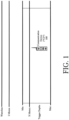
FIG. 1 is an illustration of an illustrative environment in which a communication device may be used. -
FIG. 2 is an illustration of an illustrative communication device architecture. -
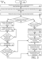
FIG. 3 is a flow diagram of an illustrative method for operating a communication device. - It will be readily understood that the solution described herein and illustrated in the appended figures could involve a wide variety of different configurations. Thus, the following more detailed description, as represented in the figures, is not intended to limit the scope of the present disclosure, but is merely representative of certain implementations in various different scenarios. While the various aspects are presented in the drawings, the drawings are not necessarily drawn to scale unless specifically indicated.
- Reference throughout this specification to features, advantages, or similar language does not imply that all of the features and advantages that may be realized should be or are in any single embodiment of the invention. Rather, language referring to the features and advantages is understood to mean that a specific feature, advantage, or characteristic described in connection with an embodiment is included in at least one embodiment of the present invention. Thus, discussions of the features and advantages, and similar language, throughout the specification may, but do not necessarily, refer to the same embodiment.
- The terms "memory," "memory device," "data store," "data storage facility" and the like each refer to a non-transitory device on which computer-readable data, programming instructions (e.g., instructions 250 of
FIG. 2 ) or both are stored. Except where specifically stated otherwise, the terms "memory," "memory device," "data store," "data storage facility" and the like are intended to include single device embodiments, embodiments in which multiple memory devices together or collectively store a set of data or instructions, as well as individual sectors within such devices. - As noted above, conventional communication devices include radios. Some of the radios have extreme immersion requirements, such as a twenty meter immersion requirement. Such radios have certain components that need maintenance due to fatigue after a certain number of dives at certain pressures and/or for certain amounts of time at certain pressures. Currently, there is not a way to accurately keep track of a radio's immersed time at depths capable of material fatigue.
- Radios that require maintenance based on time spent at immersed depths due to fatigue of components have no accurate measurement system in place to determine when maintenance is needed. Currently, systems only track the number of times a radio is put in a dive mode. There is no understanding of whether or not the radio was then subjected to any immersion. If immersed, there is no information as to how long the radio was immersed at pressures capable of fatiguing the equipment.
- Accordingly, this document concerns implementing systems and methods addressing these drawbacks of conventional radios. More specifically, this document concerns systems and methods for operating a communication device with a dome switch keypad. The dome switch keypad generally provides a pressure switch (e.g., a switch that changes an operational state when hydrostatic pressure of a certain amount is applied thereto). The pressure switch comprises a highly reliable, electrically passive (no power consumption) submersible switch capable of (a) precision triggering in certain depths and (b) deep depth survival. The purpose of the submersible switch is that is uses pressure from water submersion to activate (i.e., change states from an off state to an on state, and vice versa). The submersible switch activation can be accomplished at select depths that cause fatigue of the communication device's components (e.g., a pressure vent, a seal, and/or breathing ports/vents). For example, as shown in
FIG. 1 , the submersible switch of thecommunication device 100 is designed to be activated when it reaches ten meters below the water's surface. This activation at ten meters is repeatable (i.e., the submersible switch is reliable in that it will trigger at ten meters each time it is re-submerged under water). The present solution is not limited to the particulars of this example. - During operation, the
communication device 100 performs operations to: monitor states of snap-dome based switches of a keypad provided with the communication device; activate a second timer (e.g., a dive depth timer) when the communication device is in a dive mode and/or the snap-dome based switches are simultaneously activated; detect when maintenance of the communication device is needed based on a value of the second timer; and cause performance of communication device maintenance based on the detecting. - In some scenarios, the second timer comprises a clock for tracking an amount of time in which the communication device is immersed in water at given depths during a single immersion event or during a plurality of consecutive immersion events. A detection that maintenance is needed may be made when the value of the second timer is equal to or greater than a threshold value. The threshold value may be selected in accordance with a maximum amount of time at least one pressure sensitive component of the communication device can be immersed in water at given depths without experiencing fatigue, failure or erasure.
- In those or other scenarios, the
communication device 100 also performs operations to: transition itself from a non-dive mode in which dive timing operations of the communication device are disabled to the dive mode in which dive timing operations of the communication device are and/or are to be enabled; and activate a first timer (e.g., dive mode timer) in response to said transitioning. As noted above, the second timer comprises a clock for tracking an amount of time in which the communication device is immersed in water at given depths. The first timer comprises a clock for tracking an amount of time in which the communication device is in the dive mode. The second timer may be deactivated when the snap-dome based switches are no longer simultaneously activated, and the first timer may be deactivated when the communication device is transitioned from the dive mode. The second timer and/or first timer can be reset when the communication device maintenance has been performed. - Referring now to
FIG. 2 , there is provided an illustration of an illustrative architecture for thecommunication device 100 which is configured for carrying out the various methods described herein for accurately determining when maintenance thereof is needed.Communication device 100 can include more or less components than that shown inFIG. 2 in accordance with a given application. For example,communication device 100 may or may not include one or moreoptional pressure sensors 212. Pressure sensors are well known in the art, and therefore will not be described herein. The present solution is not limited in this regard. - As shown in
FIG. 2 , thecommunication device 100 comprises acommunication transceiver 202 coupled to anantenna 216. Communication transceivers are well known in the art, and therefore will not be described in detail herein. Still, it should be understood that the communication transceiver can comprise one or more components such as a processor, an application specific circuit, a programmable logic device, a digital signal processor, or other circuitry programmed to perform the functions described herein. Thecommunication transceiver 202 can enable end-to-end communication services in a manner known in the art. In this regard, the communication transceiver can facilitate communication of voice data from thecommunication device 100 over a communication network (e.g., a Land Mobile Radio network, a cellular network, and/or other network). - The
communication transceiver 202 is connected to aprocessor 204 comprising an electronic circuit. During operation, theprocessor 204 is configured to control thecommunication transceiver 202 for providing communication services. Theprocessor 204 also facilitates an accurate determination as to when maintenance of thecommunication device 100 is needed. The manner in which the processor facilitates such a determination will become evident as the discussion progresses. - A
memory 206,display 208, dome switch keypad 210,optional pressure sensor 212, and Input/Output ("I/O") device(s) 214 are also connected to theprocessor 204. Each of the listed devices are well known in the art, and therefore will not be described herein. In some scenarios, the dome switch keypad 210 comprises a dome switch keypad available from Snaptron Inc. of Colorado, USA. As known, a dome switch keypad comprises a plurality of keys each comprising a snap-dome based switch. The snap-dome based switch uses two circuit board traces in conjunction with a metal dome to detect when the respective key is being depressed. Such a detection is made when the metal dome is in contact with the two circuit board traces. When the key is no longer being depressed, the metal dome moves out and away from the two circuit board traces thereby indicating the key's release. Accordingly, each snap-dome based switch is transitionable between an undepressed/deactivated state and a depressed/activated state. - The
processor 204 may be configured to collect and store data generated by the display 208 (which may be a touch screen display), dome switch keypad 210,optional pressure sensor 212, I/O device(s) 214 and/or external devices (not shown). Data stored inmemory 206 can include, but is not limited to, information defining criteria for triggering adive mode timer 222, information defining criteria for triggering adive depth timer 224, threshold values, sensor data, switch state data and any other information which facilitates an accurate determination as to when maintenance of thecommunication device 100 is needed. - The
processor 204 can perform actions involving access to and use ofmemory 206 on which is stored one or more sets of instructions 250 (e.g., software code) configured to implement one or more of the methodologies, procedures, or functions described herein. The instructions 250 can also reside, completely or at least partially, within the processor 250 during execution thereof by the processor. As such, thememory 206 and theprocessor 204 can comprise machine-readable media. The term "machine-readable media", as used here, refers to a single medium or multiple media that store the one or more sets of instructions 250. The term "machine-readable media", as used here, also refers to any medium that is capable of storing, encoding or carrying a set of instructions 250 for execution by theprocessor 204 that cause such device to perform any one or more of the methodologies of the present disclosure. - The I/O device(s) 214 include(s), but is(are) not limited to, a plurality of user depressible buttons, user actuatable knobs (e.g., rotary knobs), sensor(s), microphone(s), speaker(s), camera(s), Light Emitting Diodes ("LEDs"), and/or vibrator(s). The I/O device(s) 214 may be used, for example, for entering numerical inputs, selecting various functions of the
communication device 100, and/or outputting information (e.g., alerts and notifications that maintenance of the communication device is needed). The depressible buttons of the I/O device(s) 214 may be configured as a keypad and may be part of the dome switch keypad 210. - A
battery 216 or other power source may be provided for powering the components of thecommunication device 100. Thebattery 216 may comprise a rechargeable and/or replaceable battery. Thebattery 216 may be recharged via an energy harvesting circuit (not shown). Batteries and energy harvesting circuits are well known in the art, and therefore will not be discussed here. - The communication device architecture shown in
FIG. 2 should be understood to be one possible example of a communication device system which can be used in connection with the various implementations disclosed herein. However, the systems and methods disclosed herein are not limited in this regard and any other suitable communication device system architecture can also be used without limitation. Applications that can include the apparatus and systems broadly include a variety of electronic and computer systems. In some scenarios, certain functions can be implemented in two or more specific interconnected hardware modules or devices with related control and data signals communicated between and through the modules, or as portions of an application-specific integrated circuit. Thus, the illustrative system is applicable to software, firmware, and hardware implementations. - In order to facilitate an accurate determination as to when maintenance of the
communication device 100 is needed, the communication device uses simultaneous keypad snap-dome activation by hydrostatic pressure to trigger thedive depth counter 224. Theprocessor 204 starts thedive depth counter 224 when thecommunication device 100 is in a dive mode and buttons of the keypad dome switch 210 and/or I/O device(s) is(are) activated by hydrostatic pressure. The dive depth counter 224 tracks the amount of time that thecommunication device 100 is immersed below a depth of interest. The tracked amount of time can be viewed by a user via thedisplay 208 or other output means (e.g., a digital or mechanical clock component). A user may be alerted or otherwise notified of a maintenance need for one or more fatigued components of thecommunication device 100 when the amount of time exceeds one or more pre-defined threshold values. Thedive depth counter 224 may be reset once the maintenance of thecommunication device 100 is performed. The dive depth counter information and/or maintenance information associated with thecommunication device 100 may also be communicated to an external device (e.g., a remote server) for further analysis and/or use with other communication devices. - The present solution has many novel features. For example, the present solution uses keypad hardware 210 to detect when a
communication device 100 achieves a depth of interest. This detection is made when snap-domes of the keypad dome switch 210 are actuated at the same time due to hydrostatic pressure while thecommunication device 100 is in a dive mode. Additionally or alternatively, thepressure sensor 212 can be used to facilitate such a detection. The snap-dome activation force can be designed or customized to specify the depth at which thedive depth counter 224 is to be activated. - The present solution provides an intuitive dive counter that leads to accurate maintenance on fatigued communication device parts. Currently, time spent at immersed depths is not tracked by conventional communication devices. The only tracking performed by conventional communication devices is based on when the same enter into their dive modes. Correlating the time spent in dive mode and the time spent immersed in water below a given depth can provide important information about end users that can be used to improve operations and/or architectures of communication devices with immersion requirements.
- Referring now to
FIG. 3 , there is provided a flow diagram of anillustrative method 300 for operating a communication device (e.g.,communication device 100 ofFIGS. 1-2 ).Method 300 begins with 302 and continues with 304 where an operational mode of the communication device is transitioned from a non-dive mode to a dive mode. The non-dive mode may comprise any operational mode in which dive timing operations of the communication device are disabled and/or power is supplied to I/O devices of the communication device. The dive mode comprises an operational mode in which dive timing operations of the communication device are or are to be enabled. The dive timing operations can include, but are not limited to, the tracking of a total amount of time that the communication device is in a dive mode, and/or the discontinuing the supply of power to I/O devices of the communication device. The operational mode transition can be triggered in various ways. For example, an operational mode transition is triggered in response to a user-software interaction received by the communication device and/or based on sensor data (e.g., sensor data indicating an amount of moisture in a surrounding environment). The user-software interaction may be facilitated by I/O devices (e.g.,devices 208, 210 and/or 214 ofFIG. 2 ). The transition of operational modes can be achieved by a processor (e.g.,processor 204 ofFIG. 2 ) via a change of one or more operational mode parameter values stored in an internal memory (e.g.,memory 206 ofFIG. 2 ) of the communication device. For example, one or more operational mode parameter values can be set to zero or one. The present solution is not limited to the particulars of this example. - In response to the communication device's transition into the dive mode, a dive mode timer (e.g.,
dive mode timer 222 ofFIG. 2 ) is activated by the processor as shown by 306. The dive mode timer comprises a clock for tracking an amount of time in which the communication device is in the dive mode. Clocks are well known in the art, and therefore will not be described herein. - Next in 308, the states of a keypad's snap-dome based switches are monitored by the processor. As noted above, each of the snap-dome based switches of the keypad (e.g., dome switch keypad 210 of
FIG. 2 ) has two states: an undepressed or deactivated state; and a depressed or activated state. If the snap-dome based switches are not simultaneously activated [310:NO], thenmethod 300 continues with 326. If the dive mode needs to still be active [326: YES], thenmethod 300 returns to 308. The determination of 326 as to whether or not the dive mode needs to still be active can be based on time information (e.g., has a pre-defined period of time passed since transitioning to dive mode), user-software interactions (e.g., a user uses a button or widget to turn off dive mode), and/or sensor data (e.g., sensor data specifying an amount of moisture in a surrounding environment that falls below a threshold value). In contrast, if the dive mode does not need to still be active [326:NO], then method continues with 328-330. 328-330 involve: transitioning the communication device back into the non-dive mode; and deactivating the dive mode timer. Subsequently, 332 is performed wheremethod 300 ends or other processing is performed (e.g., return to 304). - If the snap-dome based switches are simultaneously activated [310:YES], then
method 300 continues with 312-314. 312-314 involve: activating a dive depth timer of the communication device (e.g.,dive depth timer 224 ofFIG. 2 ); and monitoring the states of a keypad's snap-dome based switches. The dive depth timer comprises a clock for tracking an amount of time in which the communication device is immersed in water at given depths (e.g., depths greater than or equal to ten meters) during a single immersion event or a plurality of immersion events. Clocks are well known in the art, and therefore will not be described herein. When the keypad's snap-dome based switches are no longer simultaneously activated [316:NO], the dive depth timer is deactivated as shown by 318. - Next in 320, a determination is made as to whether the dive depth timer value is greater than or equal to a threshold value. The threshold value is selected in accordance with the maximum amount of time at least one pressure sensitive component of the communication device (e.g., pressure
sensitive component 220 ofFIG. 2 ) can be immersed in water at given depths (e.g., ten-twenty meters) without experiencing fatigue (e.g., mechanical deformation or material wear and tear), failure (e.g., material rupture, puncture, rip, tear, etc.) or erasure (e.g., electronic component erasure or loss of functionality). The pressure sensitive component(s) can include(s), but is(are) not limited to, a pressure vent, a seal, and/or a breathing ports/vent. - If the dive depth timer value is less than the threshold value [320:NO], then 332 is performed where
method 300 ends or other processing is performed (e.g., return to 304). In contrast, if the dive depth time value is greater than or equal to the threshold value [320: YES], then 322 is performed where the processor performs operations to cause the communication device maintenance to be performed. These operations can include, but are not limited to, causing an output of an indicator indicating a need for communication device maintenance, causing software to be loaded from a local non-volatile memory device to a volatile memory device, and/or causing software to be downloaded from a remote site to the communication device. The indication can include, but is not limited to, an auditory indication, a visual indication and/or a tactile indication. For example, the indication comprises emitted light, an electronic message (e.g., a displayed text message or icon), a sound, and/or a vibration. - The dive mode timer and the dive depth timer are reset when the communication device maintenance has been performed, as shown by 324. Upon completing 324, 332 is performed where
method 300 ends or other processing is performed (e.g., return to 304). - As evident from the above discussion, the present solution enables users of communication devices to track immersion times at depths of interest (e.g., depths equal to and greater than ten meters) to properly schedule maintenance of components that fatigue due to extreme hydrostatic pressures of surrounding water. The present solution also limits uncertainty of dive capabilities and protects communication devices from water ingress throughout their life cycles. The present solution also provides a means to track data of fielded communication devices to understand the actual use thereof in dive situations.
- The described features, advantages and characteristics disclosed herein may be combined in any suitable manner. One skilled in the relevant art will recognize, in light of the description herein, that the disclosed systems and/or methods can be practiced without one or more of the specific features. In other instances, additional features and advantages may be recognized in certain scenarios that may not be present in all instances.
- As used in this document, the singular form "a", "an", and "the" include plural references unless the context clearly dictates otherwise. Unless defined otherwise, all technical and scientific terms used herein have the same meanings as commonly understood by one of ordinary skill in the art. As used in this document, the term "comprising" means "including, but not limited to".
- Although the systems and methods have been illustrated and described with respect to one or more implementations and modifications will occur to others skilled in the art upon the reading and understanding of this specification and the annexed drawings. In addition, while a particular feature may have been disclosed with respect to only one of several implementations, such feature may be combined with one or more other features of the other implementations as may be desired and advantageous for any given or particular application. Thus, the scope of the disclosure herein should not be limited by any of the above descriptions. Rather, the scope of the invention should be defined in accordance with the following claims.
Claims (8)
- A method (300) for operating a communication device, comprising:transitioning (304), by a processor, the communication device from a non-dive mode in which dive timing operations of the communication device are disabled to a dive mode in which dive timing operations of the communication device are to be enabled;activating (306), by the processor, a first timer in response to said transitioning (304);monitoring (308), by the processor, states of snap-dome based switches of a keypad provided with the communication device, wherein the states of snap-dome based switches are changed by pressure;activating (312), by the processor, a second timer when the snap-dome based switches are simultaneously activated by the pressure;detecting (320), by the processor, when maintenance of the communication device is needed based on a value of the second timer; andcausing (322), by the processor, performance of communication device maintenance based on the detecting.
- The method (300) according to claim 1, wherein the second timer comprises a clock for tracking an amount of time in which the communication device is immersed in water at or below given depths during a single immersion event or during a plurality of consecutive immersion events.
- The method (300) according to claim 1, wherein a detection (320) is made that the maintenance is needed when the value of the second timer is greater than or equal to a threshold value, the threshold value being selected in accordance with a maximum amount of time at least one pressure sensitive component of the communication device can be immersed in water at or below given depths without experiencing fatigue, failure or erasure.
- The method (300) according to claim 1, wherein the second timer comprises a clock for tracking an amount of time in which the communication device is immersed in water at or below given depths, and the first timer comprises a clock for tracking an amount of time in which the communication device is in the dive mode.
- The method (300) according to claim 1, further comprising:deactivating (318) the second timer when the snap-dome based switches are no longer simultaneously activated; anddeactivating (330) the first timer when the communication device is transitioned from the dive mode.
- The method (300) according to claim 1, further comprising deactivating (318) the second timer when the snap-dome based switches are no longer simultaneously activated.
- The method (300) according to claim 1, further comprising re-setting (324) the second timer when the communication device maintenance has been performed.
- A communication device (100), comprising:a processor (204); anda non-transitory computer-readable storage medium (206) comprising programming instructions (250) that are configured to cause the processor (204) to implement a method for operating a communication device (100), wherein the programming instructions (250) comprise instructions to:cause performance of communication device (100) maintenance based on the detecting.transition the communication device (100) from a non-dive mode in which dive timing operations of the communication device (100) are disabled to a dive mode in which dive timing operations of the communication device (100) are to be enabled;activate a first timer (222) in response to said transitioning;monitor states of snap-dome based switches of a keypad (210) provided with the communication device (100), wherein the states of snap-dome based switches (210) are changed by pressure;activate a second timer (224) when the snap-dome based switches (210) are simultaneously activated by the pressure;detect when maintenance of the communication device (100) is needed based on a value of the second timer (224); and
Applications Claiming Priority (1)
| Application Number | Priority Date | Filing Date | Title |
|---|---|---|---|
| US16/689,817 US10921203B1 (en) | 2019-11-20 | 2019-11-20 | Communication system with immersion counter |
Publications (2)
| Publication Number | Publication Date |
|---|---|
| EP3826232A1 EP3826232A1 (en) | 2021-05-26 |
| EP3826232B1 true EP3826232B1 (en) | 2025-03-12 |
Family
ID=73475855
Family Applications (1)
| Application Number | Title | Priority Date | Filing Date |
|---|---|---|---|
| EP20207947.1A Active EP3826232B1 (en) | 2019-11-20 | 2020-11-17 | Communication system with immersion counter |
Country Status (3)
| Country | Link |
|---|---|
| US (1) | US10921203B1 (en) |
| EP (1) | EP3826232B1 (en) |
| IL (1) | IL278765B (en) |
Family Cites Families (25)
| Publication number | Priority date | Publication date | Assignee | Title |
|---|---|---|---|---|
| US4188825A (en) * | 1978-12-14 | 1980-02-19 | Farrar James G | Monitor for divers to avoid decompression |
| US4563758A (en) * | 1982-09-29 | 1986-01-07 | Paternostro Charles J | Underwater communicator |
| US4703139A (en) * | 1983-09-06 | 1987-10-27 | Kb Denver, Inc. | Method in a snap dome switch keyboard assembly for reducing contact bounce time |
| US4526473A (en) * | 1983-11-21 | 1985-07-02 | Zahn Iii Norman E | Heads up sports timer with electronic time display |
| US4533256A (en) * | 1983-12-29 | 1985-08-06 | Divers Supply Co., Inc. | Dive timer |
| US4611923A (en) * | 1984-11-30 | 1986-09-16 | Citizen Watch Co., Ltd. | Electronic timepiece with a depth gauge |
| EP0195636B1 (en) * | 1985-03-19 | 1991-07-10 | Citizen Watch Co. Ltd. | Wristwatch with pressure sensor |
| US4882678A (en) * | 1987-01-14 | 1989-11-21 | Oceanic Usa | Data sensing and processing device for scuba divers |
| AU2240392A (en) * | 1991-06-20 | 1993-01-25 | Lynn B. Hales | Field of view underwater dive computer system |
| JP3548628B2 (en) * | 1995-06-02 | 2004-07-28 | シチズン時計株式会社 | Electronic equipment with water depth measurement function |
| JP2003178642A (en) | 2001-12-11 | 2003-06-27 | Polymatech Co Ltd | Keypad and method for separating cross-linkable resin layer thereof |
| US7126498B2 (en) * | 2002-02-27 | 2006-10-24 | Digit Wireless, Llc | Keypad construction |
| DK1509938T3 (en) * | 2002-05-23 | 2006-09-11 | Digit Wireless Llc | Key groups and key switches |
| US7778115B2 (en) * | 2005-12-15 | 2010-08-17 | Richemont International S.A. | Depth measuring device for watches, and watches incorporating such a measuring device |
| US8243038B2 (en) * | 2009-07-03 | 2012-08-14 | Tactus Technologies | Method for adjusting the user interface of a device |
| US9588683B2 (en) * | 2008-01-04 | 2017-03-07 | Tactus Technology, Inc. | Dynamic tactile interface |
| US7895767B2 (en) * | 2008-09-12 | 2011-03-01 | Eidosmed Llc | Electronic depth gauge with variable electrical resistance sensing |
| US20110193787A1 (en) * | 2010-02-10 | 2011-08-11 | Kevin Morishige | Input mechanism for providing dynamically protruding surfaces for user interaction |
| US8638236B2 (en) | 2010-02-25 | 2014-01-28 | Qualcomm Incorporated | Methods and apparatus for applying tactile pressure sensors |
| US8446264B2 (en) | 2010-07-21 | 2013-05-21 | Research In Motion Limited | Portable electronic device having a waterproof keypad |
| CN104662497A (en) * | 2012-09-24 | 2015-05-27 | 泰克图斯科技公司 | Dynamic tactile interface and methods |
| WO2016138546A2 (en) * | 2015-02-27 | 2016-09-01 | Azoteq (Pty) Ltd | Inductance sensing |
| EP3404502B1 (en) * | 2017-05-17 | 2021-03-03 | Caverion Oyj | Condition-based maintenance of device |
| CN109839245B (en) * | 2017-11-29 | 2022-05-17 | 富泰华工业(深圳)有限公司 | Electronic device and method for judging waterproof quality assurance conditions |
| US10510504B2 (en) * | 2017-12-08 | 2019-12-17 | Eagle Technology, Llc | Force amplified low pressure depth activated switch |
-
2019
- 2019-11-20 US US16/689,817 patent/US10921203B1/en active Active
-
2020
- 2020-11-17 EP EP20207947.1A patent/EP3826232B1/en active Active
- 2020-11-17 IL IL278765A patent/IL278765B/en unknown
Also Published As
| Publication number | Publication date |
|---|---|
| IL278765B (en) | 2022-08-01 |
| IL278765A (en) | 2021-05-31 |
| US10921203B1 (en) | 2021-02-16 |
| EP3826232A1 (en) | 2021-05-26 |
Similar Documents
| Publication | Publication Date | Title |
|---|---|---|
| US9367100B2 (en) | Electronic devices with submersion detection circuitry | |
| US10663081B2 (en) | Method and apparatus for detecting water shortage for humidifier and storage medium | |
| KR20180038545A (en) | Apparatus for measuring gas integrated in a clock | |
| US8260344B2 (en) | Electronic device and control program thereof | |
| CN104544793B (en) | A kind of electronics bracelet with positioning function | |
| JP2015156703A (en) | Methods, apparatuses and systems for monitoring exposure of electronic devices to moisture and reacting to exposure | |
| JP7745549B2 (en) | Wireless sensor and smart device application method | |
| US20090085865A1 (en) | Device for underwater use and method of controlling same | |
| KR20160123879A (en) | Electronic apparatus and method for displaying screen thereof | |
| JP6638713B2 (en) | Electronic device having waterproof structure, method for detecting state of electronic device, and program | |
| JP2017135510A (en) | Electronic apparatus, control method and control program | |
| US10575775B2 (en) | Method and apparatus for monitoring hydration using a portable communication device | |
| JPWO2017204301A1 (en) | Electronic equipment and control program | |
| KR101525330B1 (en) | Smart watch and health management using smart watch | |
| JP2006509431A (en) | Mobile device interface adapted to the surrounding environment | |
| US10921203B1 (en) | Communication system with immersion counter | |
| EP1551160B1 (en) | Apparatus and method for alerting a user of increased battery power consumption in mobile terminal | |
| JP2009166752A (en) | Pressure detection device and information display system | |
| JP7003629B2 (en) | Electronic devices, device status detection methods, and programs | |
| US20190162566A1 (en) | System and method for tracking liquid consumption | |
| US20180329495A1 (en) | Notifications in a wearable device | |
| US20170203155A1 (en) | Athletic performance measuring apparatus | |
| EP1061334B1 (en) | Portable pressure measuring apparatus | |
| KR100553424B1 (en) | Wireless communication terminal having display device damage warning function and its method | |
| JP4759280B2 (en) | Electronics |
Legal Events
| Date | Code | Title | Description |
|---|---|---|---|
| PUAI | Public reference made under article 153(3) epc to a published international application that has entered the european phase |
Free format text: ORIGINAL CODE: 0009012 |
|
| STAA | Information on the status of an ep patent application or granted ep patent |
Free format text: STATUS: REQUEST FOR EXAMINATION WAS MADE |
|
| 17P | Request for examination filed |
Effective date: 20201117 |
|
| AK | Designated contracting states |
Kind code of ref document: A1 Designated state(s): AL AT BE BG CH CY CZ DE DK EE ES FI FR GB GR HR HU IE IS IT LI LT LU LV MC MK MT NL NO PL PT RO RS SE SI SK SM TR |
|
| STAA | Information on the status of an ep patent application or granted ep patent |
Free format text: STATUS: EXAMINATION IS IN PROGRESS |
|
| 17Q | First examination report despatched |
Effective date: 20230228 |
|
| REG | Reference to a national code |
Ref country code: DE Ref legal event code: R079 Free format text: PREVIOUS MAIN CLASS: H04L0012240000 Ipc: H04L0041082000 Ref country code: DE Ref legal event code: R079 Ref document number: 602020047528 Country of ref document: DE Free format text: PREVIOUS MAIN CLASS: H04L0012240000 Ipc: H04L0041082000 |
|
| GRAP | Despatch of communication of intention to grant a patent |
Free format text: ORIGINAL CODE: EPIDOSNIGR1 |
|
| STAA | Information on the status of an ep patent application or granted ep patent |
Free format text: STATUS: GRANT OF PATENT IS INTENDED |
|
| INTG | Intention to grant announced |
Effective date: 20241202 |
|
| RIC1 | Information provided on ipc code assigned before grant |
Ipc: H04L 41/08 20220101ALI20241125BHEP Ipc: H04L 41/082 20220101AFI20241125BHEP |
|
| RAP3 | Party data changed (applicant data changed or rights of an application transferred) |
Owner name: L3HARRIS GLOBAL COMMUNICATIONS, INC. |
|
| GRAS | Grant fee paid |
Free format text: ORIGINAL CODE: EPIDOSNIGR3 |
|
| GRAA | (expected) grant |
Free format text: ORIGINAL CODE: 0009210 |
|
| STAA | Information on the status of an ep patent application or granted ep patent |
Free format text: STATUS: THE PATENT HAS BEEN GRANTED |
|
| AK | Designated contracting states |
Kind code of ref document: B1 Designated state(s): AL AT BE BG CH CY CZ DE DK EE ES FI FR GB GR HR HU IE IS IT LI LT LU LV MC MK MT NL NO PL PT RO RS SE SI SK SM TR |
|
| P01 | Opt-out of the competence of the unified patent court (upc) registered |
Free format text: CASE NUMBER: APP_5028/2025 Effective date: 20250130 |
|
| REG | Reference to a national code |
Ref country code: GB Ref legal event code: FG4D |
|
| REG | Reference to a national code |
Ref country code: CH Ref legal event code: EP |
|
| REG | Reference to a national code |
Ref country code: DE Ref legal event code: R096 Ref document number: 602020047528 Country of ref document: DE |
|
| REG | Reference to a national code |
Ref country code: IE Ref legal event code: FG4D |
|
| PG25 | Lapsed in a contracting state [announced via postgrant information from national office to epo] |
Ref country code: RS Free format text: LAPSE BECAUSE OF FAILURE TO SUBMIT A TRANSLATION OF THE DESCRIPTION OR TO PAY THE FEE WITHIN THE PRESCRIBED TIME-LIMIT Effective date: 20250612 |
|
| PG25 | Lapsed in a contracting state [announced via postgrant information from national office to epo] |
Ref country code: FI Free format text: LAPSE BECAUSE OF FAILURE TO SUBMIT A TRANSLATION OF THE DESCRIPTION OR TO PAY THE FEE WITHIN THE PRESCRIBED TIME-LIMIT Effective date: 20250312 |
|
| PG25 | Lapsed in a contracting state [announced via postgrant information from national office to epo] |
Ref country code: ES Free format text: LAPSE BECAUSE OF FAILURE TO SUBMIT A TRANSLATION OF THE DESCRIPTION OR TO PAY THE FEE WITHIN THE PRESCRIBED TIME-LIMIT Effective date: 20250312 |
|
| REG | Reference to a national code |
Ref country code: LT Ref legal event code: MG9D |
|
| PG25 | Lapsed in a contracting state [announced via postgrant information from national office to epo] |
Ref country code: NO Free format text: LAPSE BECAUSE OF FAILURE TO SUBMIT A TRANSLATION OF THE DESCRIPTION OR TO PAY THE FEE WITHIN THE PRESCRIBED TIME-LIMIT Effective date: 20250612 |
|
| PG25 | Lapsed in a contracting state [announced via postgrant information from national office to epo] |
Ref country code: HR Free format text: LAPSE BECAUSE OF FAILURE TO SUBMIT A TRANSLATION OF THE DESCRIPTION OR TO PAY THE FEE WITHIN THE PRESCRIBED TIME-LIMIT Effective date: 20250312 |
|
| REG | Reference to a national code |
Ref country code: NL Ref legal event code: MP Effective date: 20250312 |
|
| PG25 | Lapsed in a contracting state [announced via postgrant information from national office to epo] |
Ref country code: LV Free format text: LAPSE BECAUSE OF FAILURE TO SUBMIT A TRANSLATION OF THE DESCRIPTION OR TO PAY THE FEE WITHIN THE PRESCRIBED TIME-LIMIT Effective date: 20250312 |
|
| PG25 | Lapsed in a contracting state [announced via postgrant information from national office to epo] |
Ref country code: GR Free format text: LAPSE BECAUSE OF FAILURE TO SUBMIT A TRANSLATION OF THE DESCRIPTION OR TO PAY THE FEE WITHIN THE PRESCRIBED TIME-LIMIT Effective date: 20250613 Ref country code: BG Free format text: LAPSE BECAUSE OF FAILURE TO SUBMIT A TRANSLATION OF THE DESCRIPTION OR TO PAY THE FEE WITHIN THE PRESCRIBED TIME-LIMIT Effective date: 20250312 |
|
| REG | Reference to a national code |
Ref country code: AT Ref legal event code: MK05 Ref document number: 1775975 Country of ref document: AT Kind code of ref document: T Effective date: 20250312 |
|
| PG25 | Lapsed in a contracting state [announced via postgrant information from national office to epo] |
Ref country code: NL Free format text: LAPSE BECAUSE OF FAILURE TO SUBMIT A TRANSLATION OF THE DESCRIPTION OR TO PAY THE FEE WITHIN THE PRESCRIBED TIME-LIMIT Effective date: 20250312 |
|
| PG25 | Lapsed in a contracting state [announced via postgrant information from national office to epo] |
Ref country code: SE Free format text: LAPSE BECAUSE OF FAILURE TO SUBMIT A TRANSLATION OF THE DESCRIPTION OR TO PAY THE FEE WITHIN THE PRESCRIBED TIME-LIMIT Effective date: 20250312 |
|
| PG25 | Lapsed in a contracting state [announced via postgrant information from national office to epo] |
Ref country code: SM Free format text: LAPSE BECAUSE OF FAILURE TO SUBMIT A TRANSLATION OF THE DESCRIPTION OR TO PAY THE FEE WITHIN THE PRESCRIBED TIME-LIMIT Effective date: 20250312 |
|
| PG25 | Lapsed in a contracting state [announced via postgrant information from national office to epo] |
Ref country code: PT Free format text: LAPSE BECAUSE OF FAILURE TO SUBMIT A TRANSLATION OF THE DESCRIPTION OR TO PAY THE FEE WITHIN THE PRESCRIBED TIME-LIMIT Effective date: 20250714 |
|
| PG25 | Lapsed in a contracting state [announced via postgrant information from national office to epo] |
Ref country code: IT Free format text: LAPSE BECAUSE OF FAILURE TO SUBMIT A TRANSLATION OF THE DESCRIPTION OR TO PAY THE FEE WITHIN THE PRESCRIBED TIME-LIMIT Effective date: 20250312 Ref country code: PL Free format text: LAPSE BECAUSE OF FAILURE TO SUBMIT A TRANSLATION OF THE DESCRIPTION OR TO PAY THE FEE WITHIN THE PRESCRIBED TIME-LIMIT Effective date: 20250312 |
|
| PG25 | Lapsed in a contracting state [announced via postgrant information from national office to epo] |
Ref country code: AT Free format text: LAPSE BECAUSE OF FAILURE TO SUBMIT A TRANSLATION OF THE DESCRIPTION OR TO PAY THE FEE WITHIN THE PRESCRIBED TIME-LIMIT Effective date: 20250312 |
|
| PG25 | Lapsed in a contracting state [announced via postgrant information from national office to epo] |
Ref country code: CZ Free format text: LAPSE BECAUSE OF FAILURE TO SUBMIT A TRANSLATION OF THE DESCRIPTION OR TO PAY THE FEE WITHIN THE PRESCRIBED TIME-LIMIT Effective date: 20250312 Ref country code: EE Free format text: LAPSE BECAUSE OF FAILURE TO SUBMIT A TRANSLATION OF THE DESCRIPTION OR TO PAY THE FEE WITHIN THE PRESCRIBED TIME-LIMIT Effective date: 20250312 |
|
| PG25 | Lapsed in a contracting state [announced via postgrant information from national office to epo] |
Ref country code: RO Free format text: LAPSE BECAUSE OF FAILURE TO SUBMIT A TRANSLATION OF THE DESCRIPTION OR TO PAY THE FEE WITHIN THE PRESCRIBED TIME-LIMIT Effective date: 20250312 |
|
| PG25 | Lapsed in a contracting state [announced via postgrant information from national office to epo] |
Ref country code: SK Free format text: LAPSE BECAUSE OF FAILURE TO SUBMIT A TRANSLATION OF THE DESCRIPTION OR TO PAY THE FEE WITHIN THE PRESCRIBED TIME-LIMIT Effective date: 20250312 |
|
| PG25 | Lapsed in a contracting state [announced via postgrant information from national office to epo] |
Ref country code: IS Free format text: LAPSE BECAUSE OF FAILURE TO SUBMIT A TRANSLATION OF THE DESCRIPTION OR TO PAY THE FEE WITHIN THE PRESCRIBED TIME-LIMIT Effective date: 20250712 |
|
| REG | Reference to a national code |
Ref country code: DE Ref legal event code: R097 Ref document number: 602020047528 Country of ref document: DE |
|
| PGFP | Annual fee paid to national office [announced via postgrant information from national office to epo] |
Ref country code: GB Payment date: 20251127 Year of fee payment: 6 |
|
| PG25 | Lapsed in a contracting state [announced via postgrant information from national office to epo] |
Ref country code: DK Free format text: LAPSE BECAUSE OF FAILURE TO SUBMIT A TRANSLATION OF THE DESCRIPTION OR TO PAY THE FEE WITHIN THE PRESCRIBED TIME-LIMIT Effective date: 20250312 |
|
| PLBE | No opposition filed within time limit |
Free format text: ORIGINAL CODE: 0009261 |
|
| STAA | Information on the status of an ep patent application or granted ep patent |
Free format text: STATUS: NO OPPOSITION FILED WITHIN TIME LIMIT |
|
| REG | Reference to a national code |
Ref country code: CH Ref legal event code: L10 Free format text: ST27 STATUS EVENT CODE: U-0-0-L10-L00 (AS PROVIDED BY THE NATIONAL OFFICE) Effective date: 20260121 |
|
| 26N | No opposition filed |
Effective date: 20251215 |
|
| REG | Reference to a national code |
Ref country code: DE Ref legal event code: R119 Ref document number: 602020047528 Country of ref document: DE |
|
| REG | Reference to a national code |
Ref country code: CH Ref legal event code: H13 Free format text: ST27 STATUS EVENT CODE: U-0-0-H10-H13 (AS PROVIDED BY THE NATIONAL OFFICE) Effective date: 20260623 |
|
| PG25 | Lapsed in a contracting state [announced via postgrant information from national office to epo] |
Ref country code: LT Free format text: LAPSE BECAUSE OF FAILURE TO SUBMIT A TRANSLATION OF THE DESCRIPTION OR TO PAY THE FEE WITHIN THE PRESCRIBED TIME-LIMIT Effective date: 20250312 |
|
| PG25 | Lapsed in a contracting state [announced via postgrant information from national office to epo] |
Ref country code: MC Free format text: LAPSE BECAUSE OF FAILURE TO SUBMIT A TRANSLATION OF THE DESCRIPTION OR TO PAY THE FEE WITHIN THE PRESCRIBED TIME-LIMIT Effective date: 20250312 |
|
| PG25 | Lapsed in a contracting state [announced via postgrant information from national office to epo] |
Ref country code: LU Free format text: LAPSE BECAUSE OF NON-PAYMENT OF DUE FEES Effective date: 20251117 Ref country code: CH Free format text: LAPSE BECAUSE OF NON-PAYMENT OF DUE FEES Effective date: 20251130 |