EP3826090B1 - System and method for detecting misalignment of electrodes - Google Patents
System and method for detecting misalignment of electrodes Download PDFInfo
- Publication number
- EP3826090B1 EP3826090B1 EP19837103.1A EP19837103A EP3826090B1 EP 3826090 B1 EP3826090 B1 EP 3826090B1 EP 19837103 A EP19837103 A EP 19837103A EP 3826090 B1 EP3826090 B1 EP 3826090B1
- Authority
- EP
- European Patent Office
- Prior art keywords
- angle
- coordinates
- reference jig
- electrode assembly
- vertex
- Prior art date
- Legal status (The legal status is an assumption and is not a legal conclusion. Google has not performed a legal analysis and makes no representation as to the accuracy of the status listed.)
- Active
Links
Images




Classifications
-
- H—ELECTRICITY
- H01—ELECTRIC ELEMENTS
- H01M—PROCESSES OR MEANS, e.g. BATTERIES, FOR THE DIRECT CONVERSION OF CHEMICAL ENERGY INTO ELECTRICAL ENERGY
- H01M10/00—Secondary cells; Manufacture thereof
- H01M10/04—Construction or manufacture in general
- H01M10/0436—Small-sized flat cells or batteries for portable equipment
-
- G—PHYSICS
- G01—MEASURING; TESTING
- G01B—MEASURING LENGTH, THICKNESS OR SIMILAR LINEAR DIMENSIONS; MEASURING ANGLES; MEASURING AREAS; MEASURING IRREGULARITIES OF SURFACES OR CONTOURS
- G01B15/00—Measuring arrangements characterised by the use of electromagnetic waves or particle radiation, e.g. by the use of microwaves, X-rays, gamma rays or electrons
-
- H—ELECTRICITY
- H01—ELECTRIC ELEMENTS
- H01M—PROCESSES OR MEANS, e.g. BATTERIES, FOR THE DIRECT CONVERSION OF CHEMICAL ENERGY INTO ELECTRICAL ENERGY
- H01M10/00—Secondary cells; Manufacture thereof
- H01M10/04—Construction or manufacture in general
-
- H—ELECTRICITY
- H01—ELECTRIC ELEMENTS
- H01M—PROCESSES OR MEANS, e.g. BATTERIES, FOR THE DIRECT CONVERSION OF CHEMICAL ENERGY INTO ELECTRICAL ENERGY
- H01M10/00—Secondary cells; Manufacture thereof
- H01M10/04—Construction or manufacture in general
- H01M10/0413—Large-sized flat cells or batteries for motive or stationary systems with plate-like electrodes
-
- H—ELECTRICITY
- H01—ELECTRIC ELEMENTS
- H01M—PROCESSES OR MEANS, e.g. BATTERIES, FOR THE DIRECT CONVERSION OF CHEMICAL ENERGY INTO ELECTRICAL ENERGY
- H01M10/00—Secondary cells; Manufacture thereof
- H01M10/05—Accumulators with non-aqueous electrolyte
- H01M10/058—Construction or manufacture
- H01M10/0585—Construction or manufacture of accumulators having only flat construction elements, i.e. flat positive electrodes, flat negative electrodes and flat separators
-
- H—ELECTRICITY
- H01—ELECTRIC ELEMENTS
- H01M—PROCESSES OR MEANS, e.g. BATTERIES, FOR THE DIRECT CONVERSION OF CHEMICAL ENERGY INTO ELECTRICAL ENERGY
- H01M10/00—Secondary cells; Manufacture thereof
- H01M10/42—Methods or arrangements for servicing or maintenance of secondary cells or secondary half-cells
- H01M10/4285—Testing apparatus
-
- Y—GENERAL TAGGING OF NEW TECHNOLOGICAL DEVELOPMENTS; GENERAL TAGGING OF CROSS-SECTIONAL TECHNOLOGIES SPANNING OVER SEVERAL SECTIONS OF THE IPC; TECHNICAL SUBJECTS COVERED BY FORMER USPC CROSS-REFERENCE ART COLLECTIONS [XRACs] AND DIGESTS
- Y02—TECHNOLOGIES OR APPLICATIONS FOR MITIGATION OR ADAPTATION AGAINST CLIMATE CHANGE
- Y02E—REDUCTION OF GREENHOUSE GAS [GHG] EMISSIONS, RELATED TO ENERGY GENERATION, TRANSMISSION OR DISTRIBUTION
- Y02E60/00—Enabling technologies; Technologies with a potential or indirect contribution to GHG emissions mitigation
- Y02E60/10—Energy storage using batteries
-
- Y—GENERAL TAGGING OF NEW TECHNOLOGICAL DEVELOPMENTS; GENERAL TAGGING OF CROSS-SECTIONAL TECHNOLOGIES SPANNING OVER SEVERAL SECTIONS OF THE IPC; TECHNICAL SUBJECTS COVERED BY FORMER USPC CROSS-REFERENCE ART COLLECTIONS [XRACs] AND DIGESTS
- Y02—TECHNOLOGIES OR APPLICATIONS FOR MITIGATION OR ADAPTATION AGAINST CLIMATE CHANGE
- Y02P—CLIMATE CHANGE MITIGATION TECHNOLOGIES IN THE PRODUCTION OR PROCESSING OF GOODS
- Y02P70/00—Climate change mitigation technologies in the production process for final industrial or consumer products
- Y02P70/50—Manufacturing or production processes characterised by the final manufactured product
Definitions
- the present invention relates to an inspection method of a rechargeable battery, and more particularly, to provide a system and method capable of easily detecting an alignment state of electrodes of a rechargeable battery having a stacked electrode assembly.
- a rechargeable battery may be repeatedly charged and discharged, unlike a primary battery.
- a low-capacity rechargeable battery is used for small portable electronic devices such as a mobile phone, a notebook computer, and a camcorder, and a large-capacity rechargeable battery is used as a power supply for driving a motor such as for a hybrid vehicle.
- Such a rechargeable battery includes an electrode assembly having a structure in which a positive electrode, a separator, and a negative electrode are alternately stacked, a case for accommodating the electrode assembly therein, a cap plate for sealing an opening of the case, and an electrode terminal disposed on the cap plate to be electrically connected to the electrode assembly.
- the electrode assembly may have a jelly roll structure formed by being spiral-wound in a state in which a positive electrode, a separator, and a negative electrode are stacked, or may have a stacked structure in which a positive electrode, a separator, and a negative electrode are individually repeatedly stacked.
- the structure of the stacked electrode assembly is formed by repeatedly stacking the positive electrode, the separator, and the negative electrode, which are formed separately, and affects the safety of the secondary battery depending on an alignment state with each other.
- KR 2011-0017947 A discloses a system for detecting the misalignment of positive and negative electrodes of a stacked electrode assembly forming a rechargeable battery based on an X-ray imaging of two corners of said assembly at two distinct angles.
- An aspect of the present invention is to provide a system according to claim 1 and a method according to claim 5 for detecting misalignment of electrodes that can easily grasp an alignment state of electrodes of a stacked electrode assembly.
- An exemplary embodiment of the present invention provides a misalignment detecting system including: a reference jig on which an electrode assembly is disposed; a beam generator configured to irradiate X-rays at a first angle and a second angle with respect to any one corner of the electrode assembly and the reference jig; and a calculator configured to calculate position coordinates of a corner of the electrode assembly at the corner of the reference jig.
- the reference jig may have a step portion that is spaced from the corner of the reference jig by a predetermined distance and protrudes to an upper portion of the reference jig.
- the calculator may compensate coordinates calculated by comparing position coordinates of a corner of the step portion at the corner of the reference jig with an actual measured position value.
- the electrode assembly may be a stacked electrode assembly.
- An exemplary embodiment of the present invention provides a method of detecting misalignment of electrodes of an electrode assembly, including: disposing the electrode assembly on the reference jig; obtaining first coordinates of vertices of each of positive and negative electrodes positioned at first corners of the reference jig and the electrode assembly; calculating a first distance between a vertex of each negative electrode and a vertex of each positive electrode in the electrode assembly disposed at the first coordinates; and determining misalignment of the positive electrode and the negative electrode by comparing the first distance and a reference distance.
- the obtaining of the first coordinates includes: performing first imaging of the first corners at a first angle; and performing second X-ray imaging of the first corners at a second angle, and the first coordinates may be obtained from a first X-ray image and a second X-ray image.
- the method may further include compensating a distance value and coordinates measured by obtaining a measured distance for a distance between a vertex of the reference jig positioned at the first coordinates and a vertex of a step portion of the reference jig and an actual angle irradiated from an actually measured distance during actual imaging.
- the method may further include obtaining second coordinates of vertices positioned at second corners of the reference jig and the electrode assembly, and the obtaining the second coordinates may include: performing third X-ray imaging of the second corners at the first angle; and performing fourth X-ray imaging of the second corners at the second angle.
- the method may further include compensating a distance value and coordinates measured by obtaining a measured distance for a distance between a vertex of the reference jig positioned at the second coordinates and a vertex of a step portion of the reference jig and an actual angle irradiated from an actually measured distance during actual imaging.
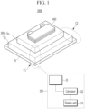
- FIG. 1 illustrates schematic diagram showing an X-ray imaging device according to an exemplary embodiment of the present invention
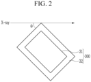
- FIG. 2 illustrates a schematic a top plan view for describing X-ray imaging.
- the X-ray imaging device 1000 includes: a pedestal 10 on which an object is disposed; an imaging unit 200 for imaging an object; and a reference jig 300 positioned on the pedestal 10.
- the imaging unit 200 includes a beam generator 21 for irradiating X-rays, a calculator 22 for storing and analyzing an image, and a display unit 23 for displaying the image or data.
- the calculator 22 may calculate angles, distances, and coordinates from a target object to be imaged such as a reference jig or an electrode assembly from the image.
- the reference jig 300 is for checking an irradiation angle of X-rays such that the X-rays can be incident on the target object at a predetermined angle.
- the reference jig 300 has a thickness, and a stepped portion 32 may be formed at an upper portion of a base portion 31 of the reference jig 300 (however, hereinafter, the base portion is not separately distinguished, and is referred to as the reference jig).
- a point where two sides of the reference jig 300 meet or a point where two sides of the step portion 32 meet is referred to as a vertex.
- the X-rays may be irradiated at a predetermined angle ⁇ , e.g., the first angle and the second angle, to a first corner C1 and a second corner C2 of the reference jig, and in this case, the first angle may be 30 degrees and the second angle may be 45 degrees.
- ⁇ e.g., the first angle and the second angle
- FIG. 3 illustrates a schematically exploded perspective view of an electrode assembly according to an exemplary embodiment of the present invention
- FIG. 4 illustrates a method of checking alignment of electrodes according to an exemplary embodiment of the present invention.
- an electrode assembly 400 to be checked for alignment is disposed in the x-ray imaging device 1000.
- the electrode assembly 400 may be disposed within a boundary line of the stepped portion 32.
- the electrode assembly according to the exemplary embodiment of the present invention is a stacked type made by repeatedly stacking a negative electrode 41 and a positive electrode 42 with a separator 43 disposed therebetween.
- the separator 43 may be a polymer film that allows lithium ions to pass therethrough.
- the negative electrode 41 includes an active layer 41a formed by coating an active material on a current collector of a thin metal plate, and an uncoated region 41b where the thin metal plate is exposed by coating no active material thereon.
- a thin metal plate of the negative electrode 41 may be a thin copper (Cu) plate.
- the positive electrode 42 includes an active layer 42a formed by coating an active material on a current collector of a thin metal plate, and an uncoated region 42b where the thin metal plate is exposed by coating no active material thereon.
- a thin metal plate of the positive electrode 42 may be a thin aluminum (Al) plate.
- a plurality of uncoated regions 41b and 42b with a same polarity may be electrically connected to each other to be electrically connected to an outer terminal.
- the uncoated regions 41b and 42 may protrude in a same direction (see FIG. 1 and FIG. 4 ), but the present invention is not limited thereto, and may protrude in opposite directions.
- the electrode assembly 400 may be sealed in a pouch-type case (not illustrated), and may protrude out of the pouch through the uncoated regions 41b and 42b or a connection member (not illustrated) connected to the uncoated regions 41b and 42b to be connected to external terminals.
- one negative electrode 41 and one positive electrode 42 included in the electrode assembly are illustrated as the electrode assembly for convenience of description.
- first X-ray imaging is performed at a first angle ⁇ 1
- second X-ray imaging is performed at a second angle ⁇ 2.
- the first angle ⁇ 1 may be 45 degrees
- the second angle ⁇ 2 may be 30 degrees.
- third X-ray imaging is performed at the first angle ⁇ 1
- fourth X-ray imaging is performed at the second angle ⁇ 2.
- misalignment of the electrode assembly is determined from an image.
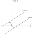
- FIG. 5 to FIG. 7 illustrate views for describing a coordinate obtaining method according to an exemplary embodiment of the present invention.
- the misalignment may be determined through X and Y coordinates obtained from the following equations, this calculation may be performed through the calculator of the imaging unit, and the image and the calculated result may be checked through the display unit.
- first corner and a second corner a method of obtaining the X and Y coordinates of two corners of the positive electrode and the negative electrode (hereinafter, referred to as a first corner and a second corner) will be described.
- vertices of the first corner C1 and the second corner C2 may be positioned on a same side.
- a distance d between two parallel straight lines may be obtained by [Equation 1].
- d b ⁇ a m 2 + 1
- a minimum distance between two parallel straight lines passing through two vertices seen by X-ray imaging may be expressed as the distance d as shown in [Equation 1] and FIG. 5 .
- positions of the first vertices positioned at the first corner imaged by X-rays at the first angle ⁇ 1 and the second angle ⁇ 2 according to the present invention may be represented by straight lines having gradients m 1 and m 2 , respectively, as shown in FIG. 6 .
- straight lines with respect to the first angle ⁇ 1 and the second angle ⁇ 2 of the second corner may have opposite gradients as illustrated in FIG. 7 .
- coordinates of a first vertex P1 of the reference jig 300 at the first corner and a second vertex P2 of the step 32 may be obtained from a straight line illustrated in FIG. 8 .
- FIG. 8 illustrates a top plan view showing a reference jig and an electrode assembly according to an exemplary embodiment of the present invention
- FIG. 9 illustrates a schematic cross-sectional view of the reference jig and the electrode assembly of FIG. 8 imaged at a first angle and a second angle
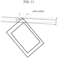
- FIG. 10 and FIG. 11 illustrate views for describing a method of obtaining a distance between vertices according to an exemplary embodiment of the present invention.
- a vertex of the reference jig 300 is referred to as a first vertex P1
- a vertex of the step portion 32 is referred to as a second vertex P2
- a vertex of the negative electrode 41 is referred to as a third vertex P3
- a vertex of the positive electrode 42 is referred to as a fourth vertex P4.
- a vertex of the reference jig 300 is referred to as a fifth vertex P5
- a vertex of the step portion 32 is referred to as a sixth vertex P6
- a vertex of the negative electrode 41 is referred to as a seventh vertex P7
- a vertex of the positive electrode 42 is referred to as an eighth vertex P8.
- coordinates of the first vertex P1 of the reference jig 300 positioned at the first corner and the second vertex P2 of the step portion 32 may be obtained by using a first straight line YY1 and a second straight line YY2 in which the gradient m 1 is parallel at the first angle ⁇ 1 and a third straight line YO1 and a fourth straight line YO2 in which the gradient m 2 is parallel at the second angle ⁇ 2.
- straight lines passing through the vertices of the negative electrode and the positive electrode are referred to as Y1, Y2, ... (the negative electrode and the positive electrode are alternately 1, 2, 3, 4, ..., and this is true in the following), and at the second angle ⁇ 2, straight lines passing through the vertices of the negative electrode and the positive electrode are referred to as W1, W2, ....
- straight lines passing through the vertices of the negative electrode and the positive electrode are referred to as Y1', Y2', ...
- straight lines passing through the vertices of the negative electrode and the positive electrode are referred to as W1', W2', ....
- h i a distance between the first vertex P1 and the third vertex P3 illustrated in FIG. 8 and FIG. 9
- h i a distance between the first vertex P1 and the third vertex P3 illustrated in FIG. 8 and FIG. 9
- e i a distance between the first vertex P1 and the fourth vertex P4
- r1 and r2 a distance between the reference first vertex P1 and the second vertex P2 at the first angle ⁇ 1 and the second angle ⁇ 2, respectively.
- a distance between two parallel straight lines shown in FIG. 8 may be obtained from [Equation 1].
- m 1 and m 2 may be respectively obtained by using tan ( ⁇ 1) and tan ( ⁇ 2).
- the coordinates from the vertex P1 of the corner of the reference jig to P2, P3, and P4 and the coordinates from the vertex P5 to P6, P7, and P8 may be calculated, and distances h1, h2, h3... of the vertices P2, P3, P4, P6, P7, and P8 from the vertices P1 and P5 of the corners of the reference jig may be calculated using the calculated coordinates.
- the distance of the vertices calculated from the actual X-ray image may be different from the actually measured distance.
- a main factor is that it is imaged at an angle other than a predetermined angle (hereinafter, referred to as an actual angle) when actual X-ray imaging is performed.
- an actual imaged angle may be different from the predetermined angle. Accordingly, it is necessary to verify the imaged angle of the X-ray imaging equipment through the reference jig 300.
- the coordinates of each vertex obtained based on the predetermined angle are also different. That is, in reference coordinates obtained according to a reference distance of the reference jig 300, the coordinates of the first vertex may be (0, 0) and the coordinates of the second vertex may be (10, 10), but the coordinates of the first vertex according to a first distance r1 obtained from the distance measured from the actually captured image may be (0, 0) and the coordinates of the second vertex may be (11, 12).
- an actual angle between an actual distance between the first vertex P1 and the second vertex P2 separated by a certain distance and a distance between the first vertex P1 and the second vertex P2 measured by X-ray imaging is obtained by using a trigonometric function as shown in FIG. 11 .
- the actual imaged angle obtained from the first distance measured from the actual image may be 32 degrees by performing the imaging by setting it to 30 degrees.
- a distance G1 between the third vertex P3 and the fourth vertex P4 may be obtained through the coordinates of the third vertex P3 and the fourth vertex P4 obtained from the coordinates calculated by the above method, and thus a distance G2 between 7 th and 8 th vertices may be obtained through the coordinates of the 7 th and 8 th vertices P7 and P8.
- the distances G1 and G2 between the vertices are relative distances between the vertices.
- the third vertex P3 and the seventh vertex P7 are the vertices of the negative electrode 41 and the fourth vertex P4 and the eighth vertex P8 are the vertices of the positive electrode 42, a relative position between the positive electrode and the negative electrode and a distance therebetween may be recognized through these coordinates.
- XY coordinates may be obtained for the two corners (C1, C2), and predetermined horizontal or vertical lengths of the positive electrode and the negative electrode may be added to recognize positions of the remaining two corners (C3, C4).
- misalignment is determined depending on relative stacking positions of the positive electrode and the negative electrode. Due to characteristics of the battery, the positive electrode should be formed smaller than the negative electrode, and a boundary line of the positive electrode should be stacked such that it does not protrude outside that of the negative electrode. When the boundary line (or vertex) of the positive electrode is positioned outside the boundary line of the negative electrode, the positive electrode and the negative electrode are misaligned, and it is determined as defective.
- a shape in which the positive electrode and the negative electrode are stacked i.e., a relative position between the positive electrode and the negative electrode which are adjacent to each other, may be easily recognized by finding the coordinates of the two corners of the positive electrode and the negative electrode.
- coordinates of each vertex of all positive and negative electrodes included in the electrode assembly may be obtained by using only images imaged at different angles for each corner, to determine misalignment for each electrode.
Landscapes
- Engineering & Computer Science (AREA)
- Manufacturing & Machinery (AREA)
- Chemical & Material Sciences (AREA)
- Chemical Kinetics & Catalysis (AREA)
- Electrochemistry (AREA)
- General Chemical & Material Sciences (AREA)
- Physics & Mathematics (AREA)
- Electromagnetism (AREA)
- General Physics & Mathematics (AREA)
- Length-Measuring Devices Using Wave Or Particle Radiation (AREA)
Description
- The present invention relates to an inspection method of a rechargeable battery, and more particularly, to provide a system and method capable of easily detecting an alignment state of electrodes of a rechargeable battery having a stacked electrode assembly.
- A rechargeable battery may be repeatedly charged and discharged, unlike a primary battery. A low-capacity rechargeable battery is used for small portable electronic devices such as a mobile phone, a notebook computer, and a camcorder, and a large-capacity rechargeable battery is used as a power supply for driving a motor such as for a hybrid vehicle.
- Such a rechargeable battery includes an electrode assembly having a structure in which a positive electrode, a separator, and a negative electrode are alternately stacked, a case for accommodating the electrode assembly therein, a cap plate for sealing an opening of the case, and an electrode terminal disposed on the cap plate to be electrically connected to the electrode assembly.
- The electrode assembly may have a jelly roll structure formed by being spiral-wound in a state in which a positive electrode, a separator, and a negative electrode are stacked, or may have a stacked structure in which a positive electrode, a separator, and a negative electrode are individually repeatedly stacked.
- Among them, the structure of the stacked electrode assembly is formed by repeatedly stacking the positive electrode, the separator, and the negative electrode, which are formed separately, and affects the safety of the secondary battery depending on an alignment state with each other.
- Accordingly, it is necessary to inspect their alignment during a manufacturing process, but it is not easy to visually grasp a stacked state of the positive electrode and the negative electrode in the form of a thin plate, and accuracy is poor.
-
KR 2011-0017947 A - An aspect of the present invention is to provide a system according to claim 1 and a method according to claim 5 for detecting misalignment of electrodes that can easily grasp an alignment state of electrodes of a stacked electrode assembly.
- An exemplary embodiment of the present invention provides a misalignment detecting system including: a reference jig on which an electrode assembly is disposed; a beam generator configured to irradiate X-rays at a first angle and a second angle with respect to any one corner of the electrode assembly and the reference jig; and a calculator configured to calculate position coordinates of a corner of the electrode assembly at the corner of the reference jig.
- The reference jig may have a step portion that is spaced from the corner of the reference jig by a predetermined distance and protrudes to an upper portion of the reference jig.
- The calculator may compensate coordinates calculated by comparing position coordinates of a corner of the step portion at the corner of the reference jig with an actual measured position value.
- The electrode assembly may be a stacked electrode assembly.
- An exemplary embodiment of the present invention provides a method of detecting misalignment of electrodes of an electrode assembly, including: disposing the electrode assembly on the reference jig; obtaining first coordinates of vertices of each of positive and negative electrodes positioned at first corners of the reference jig and the electrode assembly; calculating a first distance between a vertex of each negative electrode and a vertex of each positive electrode in the electrode assembly disposed at the first coordinates; and determining misalignment of the positive electrode and the negative electrode by comparing the first distance and a reference distance.
- The obtaining of the first coordinates includes: performing first imaging of the first corners at a first angle; and performing second X-ray imaging of the first corners at a second angle, and the first coordinates may be obtained from a first X-ray image and a second X-ray image.
- The method may further include compensating a distance value and coordinates measured by obtaining a measured distance for a distance between a vertex of the reference jig positioned at the first coordinates and a vertex of a step portion of the reference jig and an actual angle irradiated from an actually measured distance during actual imaging.
- The method may further include obtaining second coordinates of vertices positioned at second corners of the reference jig and the electrode assembly, and the obtaining the second coordinates may include: performing third X-ray imaging of the second corners at the first angle; and performing fourth X-ray imaging of the second corners at the second angle.
- The method may further include compensating a distance value and coordinates measured by obtaining a measured distance for a distance between a vertex of the reference jig positioned at the second coordinates and a vertex of a step portion of the reference jig and an actual angle irradiated from an actually measured distance during actual imaging.
- When the misalignment detecting system according to the exemplary embodiment of the present invention is used, coordinates of corner vertices of the positive electrode and the negative electrode may be easily obtained. Accordingly, a relative distance between the positive electrode and the negative electrode may be obtained from the coordinates, thereby easily detecting misalignment therebetween.
-
-
FIG. 1 illustrates schematic diagram showing an X-ray imaging device according to an exemplary embodiment of the present invention. -
FIG. 2 illustrates a schematic a top plan view for describing X-ray imaging. -
FIG. 3 illustrates a schematically exploded perspective view of an electrode assembly according to an exemplary embodiment of the present invention. -
FIG. 4 illustrates a method of checking alignment of electrodes according to an exemplary embodiment of the present invention. -
FIG. 5 to FIG. 7 illustrate views for describing a coordinate obtaining method according to an exemplary embodiment of the present invention. -
FIG. 8 illustrates a top plan view showing a reference jig and an electrode assembly according to an exemplary embodiment of the present invention. -
FIG. 9 illustrates a schematic cross-sectional view of the reference jig and the electrode assembly ofFIG. 8 imaged at a first angle and a second angle. -
FIG. 10 andFIG. 11 illustrate views for describing a method of obtaining a distance between vertices according to an exemplary embodiment of the present invention. - The present invention will be described more fully hereinafter with reference to the accompanying drawings, in which exemplary embodiments of the invention are shown. As those skilled in the art would realize, the described embodiments may be modified in various different ways, all without departing from the scope of the present invention.
- To clearly describe the present invention, parts that are irrelevant to the description are omitted, and like numerals refer to like or similar constituent elements throughout the specification.
- Further, since sizes and thicknesses of constituent members shown in the accompanying drawings are arbitrarily given for better understanding and ease of description, the present invention is not limited to the illustrated sizes and thicknesses.
- Throughout this specification and the claims that follow, when it is described that an element is "coupled/connected" to another element, the element may be "directly coupled/connected" to the other element or "indirectly coupled/connected" to the other element through a third element. In addition, unless explicitly described to the contrary, the word "comprise" and variations such as "comprises" or "comprising" will be understood to imply the inclusion of stated elements but not the exclusion of any other elements.
- In the drawings, the thicknesses of layers, films, panels, regions, etc., are exaggerated for clarity. In the drawings, for better understanding and ease of description, the thicknesses of some layers and areas are exaggerated. It will be understood that when an element such as a layer, film, region, or substrate is referred to as being "on" another element, it can be directly on the other element or intervening elements may also be present. Further, in the specification, the word "on" or "above" means positioned on or below the object portion, and does not necessarily mean positioned on the upper side of the object portion based on a gravitational direction.
- Hereinafter, a rechargeable battery according to an exemplary embodiment of the present invention will be described in detail accompanying drawings.
-
FIG. 1 illustrates schematic diagram showing an X-ray imaging device according to an exemplary embodiment of the present invention, andFIG. 2 illustrates a schematic a top plan view for describing X-ray imaging. - As illustrated in
FIG. 1 , theX-ray imaging device 1000 according to the exemplary embodiment of the present invention includes: a pedestal 10 on which an object is disposed; animaging unit 200 for imaging an object; and areference jig 300 positioned on the pedestal 10. - The
imaging unit 200 includes abeam generator 21 for irradiating X-rays, acalculator 22 for storing and analyzing an image, and adisplay unit 23 for displaying the image or data. - The
calculator 22 may calculate angles, distances, and coordinates from a target object to be imaged such as a reference jig or an electrode assembly from the image. - The
reference jig 300 is for checking an irradiation angle of X-rays such that the X-rays can be incident on the target object at a predetermined angle. - The
reference jig 300 has a thickness, and astepped portion 32 may be formed at an upper portion of abase portion 31 of the reference jig 300 (however, hereinafter, the base portion is not separately distinguished, and is referred to as the reference jig). Hereinafter, a point where two sides of the reference jig 300 meet or a point where two sides of thestep portion 32 meet is referred to as a vertex. - As illustrated in
FIG. 2 , the X-rays may be irradiated at a predetermined angle θ, e.g., the first angle and the second angle, to a first corner C1 and a second corner C2 of the reference jig, and in this case, the first angle may be 30 degrees and the second angle may be 45 degrees. - Hereinafter, a method of checking alignment of an electrode plate for a rechargeable battery using an alignment checking device of
FIG. 1 andFIG. 2 will be described with reference to the drawings. -
FIG. 3 illustrates a schematically exploded perspective view of an electrode assembly according to an exemplary embodiment of the present invention, andFIG. 4 illustrates a method of checking alignment of electrodes according to an exemplary embodiment of the present invention. - First, as illustrated in
FIG. 1 , anelectrode assembly 400 to be checked for alignment is disposed in thex-ray imaging device 1000. In this case, theelectrode assembly 400 may be disposed within a boundary line of thestepped portion 32. - Referring to
FIG. 4 , the electrode assembly according to the exemplary embodiment of the present invention is a stacked type made by repeatedly stacking anegative electrode 41 and apositive electrode 42 with aseparator 43 disposed therebetween. Theseparator 43 may be a polymer film that allows lithium ions to pass therethrough. - The
negative electrode 41 includes anactive layer 41a formed by coating an active material on a current collector of a thin metal plate, and anuncoated region 41b where the thin metal plate is exposed by coating no active material thereon. A thin metal plate of thenegative electrode 41 may be a thin copper (Cu) plate. - The
positive electrode 42 includes anactive layer 42a formed by coating an active material on a current collector of a thin metal plate, and anuncoated region 42b where the thin metal plate is exposed by coating no active material thereon. A thin metal plate of thepositive electrode 42 may be a thin aluminum (Al) plate. - A plurality of
uncoated regions uncoated regions FIG. 1 andFIG. 4 ), but the present invention is not limited thereto, and may protrude in opposite directions. - The
electrode assembly 400 may be sealed in a pouch-type case (not illustrated), and may protrude out of the pouch through theuncoated regions uncoated regions - Hereinafter, one
negative electrode 41 and onepositive electrode 42 included in the electrode assembly are illustrated as the electrode assembly for convenience of description. - Referring to
FIG. 3 , with respect to the first corner C1 of thereference jig 300, first X-ray imaging is performed at a first angle θ1, and second X-ray imaging is performed at a second angle θ2. - In this case, the first angle θ1 may be 45 degrees, and the second angle θ2 may be 30 degrees.
- Next, with respect to the second corner C2 of the reference jig, third X-ray imaging is performed at the first angle θ1, and fourth X-ray imaging is performed at the second angle θ2.
- Then, misalignment of the electrode assembly is determined from an image.
-
FIG. 5 to FIG. 7 illustrate views for describing a coordinate obtaining method according to an exemplary embodiment of the present invention. - The misalignment may be determined through X and Y coordinates obtained from the following equations, this calculation may be performed through the calculator of the imaging unit, and the image and the calculated result may be checked through the display unit.
- Hereinafter, a method of obtaining the X and Y coordinates of two corners of the positive electrode and the negative electrode (hereinafter, referred to as a first corner and a second corner) will be described. In this case, vertices of the first corner C1 and the second corner C2 may be positioned on a same side.
- First, as illustrated in
FIG. 5 , a distance d between two parallel straight lines may be obtained by [Equation 1].
- Accordingly, a minimum distance between two parallel straight lines passing through two vertices seen by X-ray imaging may be expressed as the distance d as shown in [Equation 1] and
FIG. 5 . - In this case, positions of the first vertices positioned at the first corner imaged by X-rays at the first angle θ1 and the second angle θ2 according to the present invention may be represented by straight lines having gradients m1 and m2, respectively, as shown in
FIG. 6 . Then, since vertices of the first corner and the second corner are positioned at opposite sides with respect to one side of the electrode, straight lines with respect to the first angle θ1 and the second angle θ2 of the second corner may have opposite gradients as illustrated inFIG. 7 . - Accordingly, coordinates of a first vertex P1 of the
reference jig 300 at the first corner and a second vertex P2 of thestep 32 may be obtained from a straight line illustrated inFIG. 8 . - This will be described in more detail below.
-
FIG. 8 illustrates a top plan view showing a reference jig and an electrode assembly according to an exemplary embodiment of the present invention,FIG. 9 illustrates a schematic cross-sectional view of the reference jig and the electrode assembly ofFIG. 8 imaged at a first angle and a second angle, andFIG. 10 andFIG. 11 illustrate views for describing a method of obtaining a distance between vertices according to an exemplary embodiment of the present invention. - As illustrated in
FIG. 8 andFIG. 9 , at the first corner, a vertex of thereference jig 300 is referred to as a first vertex P1, a vertex of thestep portion 32 is referred to as a second vertex P2, a vertex of thenegative electrode 41 is referred to as a third vertex P3, and a vertex of thepositive electrode 42 is referred to as a fourth vertex P4. Then, at the second corner, a vertex of thereference jig 300 is referred to as a fifth vertex P5, a vertex of thestep portion 32 is referred to as a sixth vertex P6, a vertex of thenegative electrode 41 is referred to as a seventh vertex P7, and a vertex of thepositive electrode 42 is referred to as an eighth vertex P8. - First, coordinates of the first vertex P1 of the
reference jig 300 positioned at the first corner and the second vertex P2 of thestep portion 32 may be obtained by using a first straight line YY1 and a second straight line YY2 in which the gradient m1 is parallel at the first angle θ1 and a third straight line YO1 and a fourth straight line YO2 in which the gradient m2 is parallel at the second angle θ2. - Hereinafter, at the first angle θ1, straight lines passing through the vertices of the negative electrode and the positive electrode are referred to as Y1, Y2, ... (the negative electrode and the positive electrode are alternately 1, 2, 3, 4, ..., and this is true in the following), and at the second angle θ2, straight lines passing through the vertices of the negative electrode and the positive electrode are referred to as W1, W2, .... At the second corner, at the first angle θ1, straight lines passing through the vertices of the negative electrode and the positive electrode are referred to as Y1', Y2', ..., and at the second angle θ2, straight lines passing through the vertices of the negative electrode and the positive electrode are referred to as W1', W2', ....
- In this case, a distance between the first vertex P1 and the third vertex P3 illustrated in
FIG. 8 andFIG. 9 is referred to as hi at the first angle θ1 and ℓi at the second angle θ2 (i = 1, 2, 3, ...., and this is true in the following). A distance between the first vertex P1 and the fourth vertex P4 is referred to as ei at the first angle θ1 and fi at the second angle θ2. Distances between the reference first vertex P1 and the second vertex P2 are referred to as r1 and r2 at the first angle θ1 and the second angle θ2, respectively. - A distance between two parallel straight lines shown in
FIG. 8 may be obtained from [Equation 1]. For example, a method of finding a distance between the first vertex P1 and the third vertex P3 will be described. Since it can be seen that a value of |b-a| in the above [Equation 1] are a and b at the gradients m1 and m2, respectively, and referring toFIG. 8 andFIG. 10 , the first straight line YY1, the second straight line Y1, the third straight line YO1, and the fourth straight line W1 are respectively y=m1x, y=m1x+ai, y=m2x, and y=m2x +bi. Accordingly, as follows, ai of the first straight line YY1 and the second straight line Y1 is obtained, and bi of the third straight line YO1 and the fourth straight line W1 is obtained. - m1 and m2 may be respectively obtained by using tan (θ1) and tan (θ2).


- Thereafter, when these equations are summarized for x and y, an intersection of the following two straight lines becomes the coordinates of the vertices.


- With a same method, at the first angle θ1 and the second angle θ2, the coordinates from the vertex P1 of the corner of the reference jig to P2, P3, and P4 and the coordinates from the vertex P5 to P6, P7, and P8 may be calculated, and distances h1, h2, h3... of the vertices P2, P3, P4, P6, P7, and P8 from the vertices P1 and P5 of the corners of the reference jig may be calculated using the calculated coordinates.
- Meanwhile, the distance of the vertices calculated from the actual X-ray image may be different from the actually measured distance. As such, there may be various factors that may cause the calculated distance of the vertices to differ from the actually measured distance, but a main factor is that it is imaged at an angle other than a predetermined angle (hereinafter, referred to as an actual angle) when actual X-ray imaging is performed.
- Even when a specific angle, e.g., 30 degrees, is set in X-ray imaging equipment and imaging is performed, an actual imaged angle may be different from the predetermined angle. Accordingly, it is necessary to verify the imaged angle of the X-ray imaging equipment through the
reference jig 300. - Therefore, when the actual imaged angle is different from the predetermined angle, the coordinates of each vertex obtained based on the predetermined angle are also different. That is, in reference coordinates obtained according to a reference distance of the
reference jig 300, the coordinates of the first vertex may be (0, 0) and the coordinates of the second vertex may be (10, 10), but the coordinates of the first vertex according to a first distance r1 obtained from the distance measured from the actually captured image may be (0, 0) and the coordinates of the second vertex may be (11, 12). - As such, when the predetermined angle and the imaged angle are different, an actual angle between an actual distance between the first vertex P1 and the second vertex P2 separated by a certain distance and a distance between the first vertex P1 and the second vertex P2 measured by X-ray imaging is obtained by using a trigonometric function as shown in
FIG. 11 . For example, the actual imaged angle obtained from the first distance measured from the actual image may be 32 degrees by performing the imaging by setting it to 30 degrees. - A distance G1 between the third vertex P3 and the fourth vertex P4 may be obtained through the coordinates of the third vertex P3 and the fourth vertex P4 obtained from the coordinates calculated by the above method, and thus a distance G2 between 7th and 8th vertices may be obtained through the coordinates of the 7th and 8th vertices P7 and P8. In this case, the distances G1 and G2 between the vertices are relative distances between the vertices.
- Since the third vertex P3 and the seventh vertex P7 are the vertices of the
negative electrode 41 and the fourth vertex P4 and the eighth vertex P8 are the vertices of thepositive electrode 42, a relative position between the positive electrode and the negative electrode and a distance therebetween may be recognized through these coordinates. - Since the
negative electrode 41 and thepositive electrode 42 have a substantially rectangular shape, XY coordinates may be obtained for the two corners (C1, C2), and predetermined horizontal or vertical lengths of the positive electrode and the negative electrode may be added to recognize positions of the remaining two corners (C3, C4). - Meanwhile, in the stacked
electrode assembly 400, misalignment is determined depending on relative stacking positions of the positive electrode and the negative electrode. Due to characteristics of the battery, the positive electrode should be formed smaller than the negative electrode, and a boundary line of the positive electrode should be stacked such that it does not protrude outside that of the negative electrode. When the boundary line (or vertex) of the positive electrode is positioned outside the boundary line of the negative electrode, the positive electrode and the negative electrode are misaligned, and it is determined as defective. - In an exemplary embodiment of the present invention, a shape in which the positive electrode and the negative electrode are stacked, i.e., a relative position between the positive electrode and the negative electrode which are adjacent to each other, may be easily recognized by finding the coordinates of the two corners of the positive electrode and the negative electrode.
- Therefore, not only the positive electrode protruding outside the boundary line of the negative electrode and being misaligned may be determined, but also a degree of misalignment from the relative distance between the positive electrode and the negative electrode may be easily recognized.
- For convenience of description, one positive electrode and one negative electrode have been described, but when the x-ray imaging device according to an exemplary embodiment of the present invention is used, coordinates of each vertex of all positive and negative electrodes included in the electrode assembly may be obtained by using only images imaged at different angles for each corner, to determine misalignment for each electrode.
- In this way, when positions of all the positive and negative electrodes are recognized, a position of the layer on which the misaligned positive or negative electrode is stacked may be recognized. Accordingly, it is possible to manufacture an electrode assembly including positive and negative electrodes in which misalignment does not occur by modifying only a stacking process of an electrode in which misalignment occurs.
- While this invention has been described in connection with what is presently considered to be practical exemplary embodiments, it is to be understood that the invention is not limited to the disclosed embodiments, but, on the contrary, is intended to cover various modifications and equivalent arrangements included within the scope of the appended claims.
Claims (8)
- A misalignment detecting system comprising:a reference jig (300) on which an electrode assembly (400) is disposed;an imaging unit (200) for imaging the reference jig and the electrode assembly, comprising a beam generator (21) configured to irradiate X-rays at a first angle and a second angle with respect to any one corner of the electrode assembly and the reference jig, wherein the second angle is different from the first angle; anda calculator (22) configured to calculate position coordinates of a corner of a positive electrode (42) and a negative electrode (41) of the electrode assembly at the corner (C1, C2) of the reference jig (C1, C2) based on the acquired images of the reference jig (300) and the electrode assembly (400) at the first and second angles with respect to said corner and to determine misalignment of the positive electrode (42) and the negative electrode (41) of the electrode assembly (400) based on the calculated position coordinates.
- The misalignment detecting system of claim 1, whereinthe reference jig (300) hasa step portion (32) that is spaced from the corner of the reference jig by a predetermined distance and protrudes to an upper portion of the reference jig.
- The misalignment detecting system of claim 2, wherein
the calculator (22) compensates coordinates calculated by comparing position coordinates of a corner of the step portion (32) at the corner of the reference jig with an actual measured position value. - The misalignment detecting system of claim 1, wherein
the electrode assembly (400) is a stacked electrode assembly. - A method for detecting misalignment of an electrode assembly through the misalignment detecting system of any one of claim 1 to claim 4, comprising:disposing the electrode assembly (400) on the reference jig (300);obtaining first coordinates of vertices of each of positive (42) and negative (41) electrodes positioned at first corners of the reference jig (300) and the electrode assembly by performing first imaging of the first corners at a first angle and performing second X-ray imaging of the first corners at a second angle, wherein the first coordinates are obtained from a first X-ray image and a second X-ray image, and wherein the second angle is different from the first angle;calculating a first distance between a vertex of each negative electrode and a vertex of each positive electrode in the electrode assembly disposed at the first coordinates; anddetermining misalignment of the positive electrode and the negative electrode by comparing the first distance and a reference distance.
- The misalignment detecting method of claim 5, further comprising
compensating a distance value and coordinates measured by obtaining a measured distance for a distance between a vertex of the reference jig (300) positioned at the first coordinates and a vertex of a step portion of the reference jig and an actual angle irradiated from an actually measured distance during actual imaging. - The misalignment detecting method of claim 6, further comprisingobtaining second coordinates of vertices positioned at second corners of the reference jig and the electrode assembly,wherein the obtaining of the second coordinates includes:performing third X-ray imaging of the second corners at the first angle; andperforming fourth X-ray imaging of the second corners at the second angle.
- The misalignment detecting method of claim 7, further comprising
compensating a distance value and coordinates measured by obtaining a measured distance for a distance between a vertex of the reference jig (300) positioned at the second coordinates and a vertex of a step portion (32) of the reference jig and an actual angle irradiated from an actually measured distance during actual imaging.
Applications Claiming Priority (2)
| Application Number | Priority Date | Filing Date | Title |
|---|---|---|---|
| KR1020180083635A KR102130027B1 (en) | 2018-07-18 | 2018-07-18 | System and method for detecting misalignment of electrode |
| PCT/KR2019/008902 WO2020017907A1 (en) | 2018-07-18 | 2019-07-18 | System and method for detecting misalignment of electrode |
Publications (3)
| Publication Number | Publication Date |
|---|---|
| EP3826090A1 EP3826090A1 (en) | 2021-05-26 |
| EP3826090A4 EP3826090A4 (en) | 2022-04-06 |
| EP3826090B1 true EP3826090B1 (en) | 2024-02-21 |
Family
ID=69164611
Family Applications (1)
| Application Number | Title | Priority Date | Filing Date |
|---|---|---|---|
| EP19837103.1A Active EP3826090B1 (en) | 2018-07-18 | 2019-07-18 | System and method for detecting misalignment of electrodes |
Country Status (6)
| Country | Link |
|---|---|
| EP (1) | EP3826090B1 (en) |
| KR (1) | KR102130027B1 (en) |
| CN (1) | CN112262490B (en) |
| HU (1) | HUE066539T2 (en) |
| PL (1) | PL3826090T3 (en) |
| WO (1) | WO2020017907A1 (en) |
Families Citing this family (9)
| Publication number | Priority date | Publication date | Assignee | Title |
|---|---|---|---|---|
| KR102938527B1 (en) * | 2020-07-30 | 2026-03-16 | 삼성디스플레이 주식회사 | Coordinate correcting method and electronic device using the same |
| DE102021117152A1 (en) * | 2021-07-02 | 2023-01-05 | Volkswagen Aktiengesellschaft | Method for determining the placement accuracy of a plurality of electrode sheets in a stack |
| CN113654493A (en) * | 2021-08-13 | 2021-11-16 | 苏州市比特优影像科技有限公司 | Quality detection method and system for laminated soft package lithium battery |
| KR20230059584A (en) * | 2021-10-26 | 2023-05-03 | 주식회사 엘지에너지솔루션 | Manufacturing method of electrode assembly |
| US20250189465A1 (en) * | 2022-03-03 | 2025-06-12 | Sk On Co., Ltd. | X-ray inspection device and x-ray inspection method |
| SE2251276A1 (en) * | 2022-11-02 | 2024-05-03 | Northvolt Ab | Determining alignment within electrode stacks |
| DE102023202492B3 (en) * | 2023-03-21 | 2024-03-28 | Volkswagen Aktiengesellschaft | Method for testing a battery element stack with regard to the position of battery element layers |
| KR20250114764A (en) * | 2024-01-22 | 2025-07-29 | 주식회사 엘지에너지솔루션 | secondary cell stacking apparatus and a contorl method of the same |
| SE2430031A1 (en) * | 2024-01-26 | 2025-07-27 | Northvolt Ab | Methods and system for determining alignment of an electrode stack |
Family Cites Families (7)
| Publication number | Priority date | Publication date | Assignee | Title |
|---|---|---|---|---|
| JP4128397B2 (en) * | 2002-06-12 | 2008-07-30 | 東芝Itコントロールシステム株式会社 | Battery inspection device |
| JP2011039014A (en) * | 2009-08-06 | 2011-02-24 | Toshiba It & Control Systems Corp | Battery inspection device |
| KR101334121B1 (en) * | 2009-10-26 | 2013-11-29 | 에스케이이노베이션 주식회사 | Electrode Inspection Device for Battery and Method of the Same. |
| JP6473924B2 (en) * | 2014-12-03 | 2019-02-27 | 東芝Itコントロールシステム株式会社 | Battery inspection device |
| KR101705330B1 (en) * | 2015-09-30 | 2017-02-10 | 인하대학교 산학협력단 | Keypoints Selection method to Find the Viewing Angle of Objects in a Stereo Camera Image |
| JP6673165B2 (en) * | 2016-11-29 | 2020-03-25 | 株式会社島津製作所 | X-ray inspection equipment for batteries |
| KR102173030B1 (en) * | 2016-12-26 | 2020-11-02 | 주식회사 엘지화학 | Align checking device and align checking method for electrode assembly |
-
2018
- 2018-07-18 KR KR1020180083635A patent/KR102130027B1/en active Active
-
2019
- 2019-07-18 EP EP19837103.1A patent/EP3826090B1/en active Active
- 2019-07-18 WO PCT/KR2019/008902 patent/WO2020017907A1/en not_active Ceased
- 2019-07-18 PL PL19837103.1T patent/PL3826090T3/en unknown
- 2019-07-18 HU HUE19837103A patent/HUE066539T2/en unknown
- 2019-07-18 CN CN201980039423.5A patent/CN112262490B/en active Active
Also Published As
| Publication number | Publication date |
|---|---|
| KR102130027B1 (en) | 2020-07-03 |
| EP3826090A1 (en) | 2021-05-26 |
| KR20200009369A (en) | 2020-01-30 |
| EP3826090A4 (en) | 2022-04-06 |
| CN112262490A (en) | 2021-01-22 |
| CN112262490B (en) | 2025-01-03 |
| HUE066539T2 (en) | 2024-08-28 |
| WO2020017907A1 (en) | 2020-01-23 |
| PL3826090T3 (en) | 2024-05-06 |
Similar Documents
| Publication | Publication Date | Title |
|---|---|---|
| EP3826090A1 (en) | System and method for detecting misalignment of electrode | |
| US20230074096A1 (en) | Battery cell electrode alignment inspection method for battery pack of vehicle | |
| KR101699809B1 (en) | Battery inspection apparatus | |
| US12051816B2 (en) | Laminated battery | |
| EP3840098B1 (en) | Electrode assembly and inspection method therefor | |
| EP4123778B1 (en) | Stacking inspection apparatus for electrode plate or unit cell | |
| KR20110014947A (en) | Battery tester | |
| US20230318093A1 (en) | Pouch-Type Secondary Battery and Method for Manufacturing the Same | |
| EP4199202A1 (en) | Pouch type battery case and pouch type secondary battery | |
| EP4184671B1 (en) | Pouch type secondary battery and battery module | |
| KR102894748B1 (en) | Vision Inspection System for Efficiently Inspecting Ultrasonic Welding Status of Secondary Battery Using Stereo Camera | |
| US20250096371A1 (en) | Pouch-Type Battery Case and Pouch Type Secondary Battery | |
| KR20190086942A (en) | Electrode assembly, method of inspecting alignment of electrode assembly, and secondary battery including electrode assembly | |
| EP4195374A1 (en) | Pouch type battery case and pouch type secondary battery | |
| US20230352773A1 (en) | Pouch-Type Secondary Battery | |
| EP4498319A1 (en) | Method and device for inspecting abnormality in electrodes | |
| KR20160049680A (en) | Battery Cell Having Reference Electrode for Detecting Electrochemical Impedance | |
| US12625045B2 (en) | Bonding state inspection apparatus and bonding state inspection method using the same | |
| KR20170093377A (en) | Device for Welding Electrode Tabs Comprising Vision Inspection Part | |
| EP4439752A1 (en) | Stack cell allowing easy checking of separator folding, and apparatus and method for inspecting separator | |
| KR20260059946A (en) | Secondary battery inspection apparatus and secondary battery inspection method | |
| KR102848104B1 (en) | Method and apparatus for measuring the height of the pouch cup portion for accommodating electrode assembly | |
| US20250329006A1 (en) | Method and system for performing electrode tab folding inspection | |
| US20250207908A1 (en) | Object thickness measuring apparatus and method | |
| KR20250126373A (en) | Camera calibration device, camera calibration mehthod using the same and electrode assembly manufacturing device including the same |
Legal Events
| Date | Code | Title | Description |
|---|---|---|---|
| STAA | Information on the status of an ep patent application or granted ep patent |
Free format text: STATUS: THE INTERNATIONAL PUBLICATION HAS BEEN MADE |
|
| PUAI | Public reference made under article 153(3) epc to a published international application that has entered the european phase |
Free format text: ORIGINAL CODE: 0009012 |
|
| STAA | Information on the status of an ep patent application or granted ep patent |
Free format text: STATUS: REQUEST FOR EXAMINATION WAS MADE |
|
| 17P | Request for examination filed |
Effective date: 20210202 |
|
| AK | Designated contracting states |
Kind code of ref document: A1 Designated state(s): AL AT BE BG CH CY CZ DE DK EE ES FI FR GB GR HR HU IE IS IT LI LT LU LV MC MK MT NL NO PL PT RO RS SE SI SK SM TR |
|
| DAV | Request for validation of the european patent (deleted) | ||
| DAX | Request for extension of the european patent (deleted) | ||
| A4 | Supplementary search report drawn up and despatched |
Effective date: 20220310 |
|
| RIC1 | Information provided on ipc code assigned before grant |
Ipc: H01M 10/42 20060101ALI20220303BHEP Ipc: G01B 15/00 20060101ALI20220303BHEP Ipc: H01M 10/0585 20100101ALI20220303BHEP Ipc: H01M 10/04 20060101AFI20220303BHEP |
|
| REG | Reference to a national code |
Ref country code: DE Ref legal event code: R079 Free format text: PREVIOUS MAIN CLASS: H01M0010040000 Ipc: G01B0015000000 Ref document number: 602019047032 Country of ref document: DE |
|
| GRAP | Despatch of communication of intention to grant a patent |
Free format text: ORIGINAL CODE: EPIDOSNIGR1 |
|
| STAA | Information on the status of an ep patent application or granted ep patent |
Free format text: STATUS: GRANT OF PATENT IS INTENDED |
|
| RIC1 | Information provided on ipc code assigned before grant |
Ipc: H01M 10/0585 20100101ALI20230829BHEP Ipc: H01M 10/42 20060101ALI20230829BHEP Ipc: G01B 15/00 20060101AFI20230829BHEP |
|
| INTG | Intention to grant announced |
Effective date: 20230921 |
|
| GRAS | Grant fee paid |
Free format text: ORIGINAL CODE: EPIDOSNIGR3 |
|
| GRAA | (expected) grant |
Free format text: ORIGINAL CODE: 0009210 |
|
| STAA | Information on the status of an ep patent application or granted ep patent |
Free format text: STATUS: THE PATENT HAS BEEN GRANTED |
|
| AK | Designated contracting states |
Kind code of ref document: B1 Designated state(s): AL AT BE BG CH CY CZ DE DK EE ES FI FR GB GR HR HU IE IS IT LI LT LU LV MC MK MT NL NO PL PT RO RS SE SI SK SM TR |
|
| REG | Reference to a national code |
Ref country code: GB Ref legal event code: FG4D |
|
| REG | Reference to a national code |
Ref country code: CH Ref legal event code: EP |
|
| REG | Reference to a national code |
Ref country code: IE Ref legal event code: FG4D |
|
| REG | Reference to a national code |
Ref country code: DE Ref legal event code: R096 Ref document number: 602019047032 Country of ref document: DE |
|
| REG | Reference to a national code |
Ref country code: SE Ref legal event code: TRGR |
|
| REG | Reference to a national code |
Ref country code: LT Ref legal event code: MG9D |
|
| REG | Reference to a national code |
Ref country code: NL Ref legal event code: MP Effective date: 20240221 |
|
| PG25 | Lapsed in a contracting state [announced via postgrant information from national office to epo] |
Ref country code: IS Free format text: LAPSE BECAUSE OF FAILURE TO SUBMIT A TRANSLATION OF THE DESCRIPTION OR TO PAY THE FEE WITHIN THE PRESCRIBED TIME-LIMIT Effective date: 20240621 |
|
| PG25 | Lapsed in a contracting state [announced via postgrant information from national office to epo] |
Ref country code: LT Free format text: LAPSE BECAUSE OF FAILURE TO SUBMIT A TRANSLATION OF THE DESCRIPTION OR TO PAY THE FEE WITHIN THE PRESCRIBED TIME-LIMIT Effective date: 20240221 |
|
| PG25 | Lapsed in a contracting state [announced via postgrant information from national office to epo] |
Ref country code: GR Free format text: LAPSE BECAUSE OF FAILURE TO SUBMIT A TRANSLATION OF THE DESCRIPTION OR TO PAY THE FEE WITHIN THE PRESCRIBED TIME-LIMIT Effective date: 20240522 |
|
| REG | Reference to a national code |
Ref country code: AT Ref legal event code: MK05 Ref document number: 1659470 Country of ref document: AT Kind code of ref document: T Effective date: 20240221 |
|
| PG25 | Lapsed in a contracting state [announced via postgrant information from national office to epo] |
Ref country code: HR Free format text: LAPSE BECAUSE OF FAILURE TO SUBMIT A TRANSLATION OF THE DESCRIPTION OR TO PAY THE FEE WITHIN THE PRESCRIBED TIME-LIMIT Effective date: 20240221 Ref country code: NL Free format text: LAPSE BECAUSE OF FAILURE TO SUBMIT A TRANSLATION OF THE DESCRIPTION OR TO PAY THE FEE WITHIN THE PRESCRIBED TIME-LIMIT Effective date: 20240221 Ref country code: RS Free format text: LAPSE BECAUSE OF FAILURE TO SUBMIT A TRANSLATION OF THE DESCRIPTION OR TO PAY THE FEE WITHIN THE PRESCRIBED TIME-LIMIT Effective date: 20240521 |
|
| PG25 | Lapsed in a contracting state [announced via postgrant information from national office to epo] |
Ref country code: ES Free format text: LAPSE BECAUSE OF FAILURE TO SUBMIT A TRANSLATION OF THE DESCRIPTION OR TO PAY THE FEE WITHIN THE PRESCRIBED TIME-LIMIT Effective date: 20240221 |
|
| PG25 | Lapsed in a contracting state [announced via postgrant information from national office to epo] |
Ref country code: AT Free format text: LAPSE BECAUSE OF FAILURE TO SUBMIT A TRANSLATION OF THE DESCRIPTION OR TO PAY THE FEE WITHIN THE PRESCRIBED TIME-LIMIT Effective date: 20240221 |
|
| PG25 | Lapsed in a contracting state [announced via postgrant information from national office to epo] |
Ref country code: RS Free format text: LAPSE BECAUSE OF FAILURE TO SUBMIT A TRANSLATION OF THE DESCRIPTION OR TO PAY THE FEE WITHIN THE PRESCRIBED TIME-LIMIT Effective date: 20240521 Ref country code: NO Free format text: LAPSE BECAUSE OF FAILURE TO SUBMIT A TRANSLATION OF THE DESCRIPTION OR TO PAY THE FEE WITHIN THE PRESCRIBED TIME-LIMIT Effective date: 20240521 Ref country code: NL Free format text: LAPSE BECAUSE OF FAILURE TO SUBMIT A TRANSLATION OF THE DESCRIPTION OR TO PAY THE FEE WITHIN THE PRESCRIBED TIME-LIMIT Effective date: 20240221 Ref country code: LT Free format text: LAPSE BECAUSE OF FAILURE TO SUBMIT A TRANSLATION OF THE DESCRIPTION OR TO PAY THE FEE WITHIN THE PRESCRIBED TIME-LIMIT Effective date: 20240221 Ref country code: IS Free format text: LAPSE BECAUSE OF FAILURE TO SUBMIT A TRANSLATION OF THE DESCRIPTION OR TO PAY THE FEE WITHIN THE PRESCRIBED TIME-LIMIT Effective date: 20240621 Ref country code: HR Free format text: LAPSE BECAUSE OF FAILURE TO SUBMIT A TRANSLATION OF THE DESCRIPTION OR TO PAY THE FEE WITHIN THE PRESCRIBED TIME-LIMIT Effective date: 20240221 Ref country code: GR Free format text: LAPSE BECAUSE OF FAILURE TO SUBMIT A TRANSLATION OF THE DESCRIPTION OR TO PAY THE FEE WITHIN THE PRESCRIBED TIME-LIMIT Effective date: 20240522 Ref country code: FI Free format text: LAPSE BECAUSE OF FAILURE TO SUBMIT A TRANSLATION OF THE DESCRIPTION OR TO PAY THE FEE WITHIN THE PRESCRIBED TIME-LIMIT Effective date: 20240221 Ref country code: ES Free format text: LAPSE BECAUSE OF FAILURE TO SUBMIT A TRANSLATION OF THE DESCRIPTION OR TO PAY THE FEE WITHIN THE PRESCRIBED TIME-LIMIT Effective date: 20240221 Ref country code: BG Free format text: LAPSE BECAUSE OF FAILURE TO SUBMIT A TRANSLATION OF THE DESCRIPTION OR TO PAY THE FEE WITHIN THE PRESCRIBED TIME-LIMIT Effective date: 20240221 Ref country code: AT Free format text: LAPSE BECAUSE OF FAILURE TO SUBMIT A TRANSLATION OF THE DESCRIPTION OR TO PAY THE FEE WITHIN THE PRESCRIBED TIME-LIMIT Effective date: 20240221 |
|
| PG25 | Lapsed in a contracting state [announced via postgrant information from national office to epo] |
Ref country code: PT Free format text: LAPSE BECAUSE OF FAILURE TO SUBMIT A TRANSLATION OF THE DESCRIPTION OR TO PAY THE FEE WITHIN THE PRESCRIBED TIME-LIMIT Effective date: 20240621 |
|
| REG | Reference to a national code |
Ref country code: HU Ref legal event code: AG4A Ref document number: E066539 Country of ref document: HU |
|
| PG25 | Lapsed in a contracting state [announced via postgrant information from national office to epo] |
Ref country code: PT Free format text: LAPSE BECAUSE OF FAILURE TO SUBMIT A TRANSLATION OF THE DESCRIPTION OR TO PAY THE FEE WITHIN THE PRESCRIBED TIME-LIMIT Effective date: 20240621 Ref country code: LV Free format text: LAPSE BECAUSE OF FAILURE TO SUBMIT A TRANSLATION OF THE DESCRIPTION OR TO PAY THE FEE WITHIN THE PRESCRIBED TIME-LIMIT Effective date: 20240221 |
|
| PG25 | Lapsed in a contracting state [announced via postgrant information from national office to epo] |
Ref country code: DK Free format text: LAPSE BECAUSE OF FAILURE TO SUBMIT A TRANSLATION OF THE DESCRIPTION OR TO PAY THE FEE WITHIN THE PRESCRIBED TIME-LIMIT Effective date: 20240221 |
|
| PG25 | Lapsed in a contracting state [announced via postgrant information from national office to epo] |
Ref country code: SM Free format text: LAPSE BECAUSE OF FAILURE TO SUBMIT A TRANSLATION OF THE DESCRIPTION OR TO PAY THE FEE WITHIN THE PRESCRIBED TIME-LIMIT Effective date: 20240221 |
|
| PG25 | Lapsed in a contracting state [announced via postgrant information from national office to epo] |
Ref country code: CZ Free format text: LAPSE BECAUSE OF FAILURE TO SUBMIT A TRANSLATION OF THE DESCRIPTION OR TO PAY THE FEE WITHIN THE PRESCRIBED TIME-LIMIT Effective date: 20240221 Ref country code: EE Free format text: LAPSE BECAUSE OF FAILURE TO SUBMIT A TRANSLATION OF THE DESCRIPTION OR TO PAY THE FEE WITHIN THE PRESCRIBED TIME-LIMIT Effective date: 20240221 |
|
| PG25 | Lapsed in a contracting state [announced via postgrant information from national office to epo] |
Ref country code: SK Free format text: LAPSE BECAUSE OF FAILURE TO SUBMIT A TRANSLATION OF THE DESCRIPTION OR TO PAY THE FEE WITHIN THE PRESCRIBED TIME-LIMIT Effective date: 20240221 |
|
| PG25 | Lapsed in a contracting state [announced via postgrant information from national office to epo] |
Ref country code: SM Free format text: LAPSE BECAUSE OF FAILURE TO SUBMIT A TRANSLATION OF THE DESCRIPTION OR TO PAY THE FEE WITHIN THE PRESCRIBED TIME-LIMIT Effective date: 20240221 Ref country code: SK Free format text: LAPSE BECAUSE OF FAILURE TO SUBMIT A TRANSLATION OF THE DESCRIPTION OR TO PAY THE FEE WITHIN THE PRESCRIBED TIME-LIMIT Effective date: 20240221 Ref country code: RO Free format text: LAPSE BECAUSE OF FAILURE TO SUBMIT A TRANSLATION OF THE DESCRIPTION OR TO PAY THE FEE WITHIN THE PRESCRIBED TIME-LIMIT Effective date: 20240221 Ref country code: EE Free format text: LAPSE BECAUSE OF FAILURE TO SUBMIT A TRANSLATION OF THE DESCRIPTION OR TO PAY THE FEE WITHIN THE PRESCRIBED TIME-LIMIT Effective date: 20240221 Ref country code: DK Free format text: LAPSE BECAUSE OF FAILURE TO SUBMIT A TRANSLATION OF THE DESCRIPTION OR TO PAY THE FEE WITHIN THE PRESCRIBED TIME-LIMIT Effective date: 20240221 Ref country code: CZ Free format text: LAPSE BECAUSE OF FAILURE TO SUBMIT A TRANSLATION OF THE DESCRIPTION OR TO PAY THE FEE WITHIN THE PRESCRIBED TIME-LIMIT Effective date: 20240221 |
|
| REG | Reference to a national code |
Ref country code: DE Ref legal event code: R097 Ref document number: 602019047032 Country of ref document: DE |
|
| PG25 | Lapsed in a contracting state [announced via postgrant information from national office to epo] |
Ref country code: IT Free format text: LAPSE BECAUSE OF FAILURE TO SUBMIT A TRANSLATION OF THE DESCRIPTION OR TO PAY THE FEE WITHIN THE PRESCRIBED TIME-LIMIT Effective date: 20240221 |
|
| PLBE | No opposition filed within time limit |
Free format text: ORIGINAL CODE: 0009261 |
|
| STAA | Information on the status of an ep patent application or granted ep patent |
Free format text: STATUS: NO OPPOSITION FILED WITHIN TIME LIMIT |
|
| PG25 | Lapsed in a contracting state [announced via postgrant information from national office to epo] |
Ref country code: IT Free format text: LAPSE BECAUSE OF FAILURE TO SUBMIT A TRANSLATION OF THE DESCRIPTION OR TO PAY THE FEE WITHIN THE PRESCRIBED TIME-LIMIT Effective date: 20240221 |
|
| 26N | No opposition filed |
Effective date: 20241122 |
|
| PG25 | Lapsed in a contracting state [announced via postgrant information from national office to epo] |
Ref country code: MC Free format text: LAPSE BECAUSE OF FAILURE TO SUBMIT A TRANSLATION OF THE DESCRIPTION OR TO PAY THE FEE WITHIN THE PRESCRIBED TIME-LIMIT Effective date: 20240221 |
|
| REG | Reference to a national code |
Ref country code: CH Ref legal event code: PL |
|
| PG25 | Lapsed in a contracting state [announced via postgrant information from national office to epo] |
Ref country code: LU Free format text: LAPSE BECAUSE OF NON-PAYMENT OF DUE FEES Effective date: 20240718 |
|
| PG25 | Lapsed in a contracting state [announced via postgrant information from national office to epo] |
Ref country code: LU Free format text: LAPSE BECAUSE OF NON-PAYMENT OF DUE FEES Effective date: 20240718 |
|
| PG25 | Lapsed in a contracting state [announced via postgrant information from national office to epo] |
Ref country code: SI Free format text: LAPSE BECAUSE OF FAILURE TO SUBMIT A TRANSLATION OF THE DESCRIPTION OR TO PAY THE FEE WITHIN THE PRESCRIBED TIME-LIMIT Effective date: 20240221 Ref country code: CH Free format text: LAPSE BECAUSE OF NON-PAYMENT OF DUE FEES Effective date: 20240731 Ref country code: BE Free format text: LAPSE BECAUSE OF NON-PAYMENT OF DUE FEES Effective date: 20240731 |
|
| REG | Reference to a national code |
Ref country code: BE Ref legal event code: MM Effective date: 20240731 |
|
| PGFP | Annual fee paid to national office [announced via postgrant information from national office to epo] |
Ref country code: GB Payment date: 20250626 Year of fee payment: 7 |
|
| PGFP | Annual fee paid to national office [announced via postgrant information from national office to epo] |
Ref country code: FR Payment date: 20250623 Year of fee payment: 7 |
|
| PG25 | Lapsed in a contracting state [announced via postgrant information from national office to epo] |
Ref country code: IE Free format text: LAPSE BECAUSE OF NON-PAYMENT OF DUE FEES Effective date: 20240718 |
|
| PGFP | Annual fee paid to national office [announced via postgrant information from national office to epo] |
Ref country code: SE Payment date: 20250626 Year of fee payment: 7 |
|
| PGFP | Annual fee paid to national office [announced via postgrant information from national office to epo] |
Ref country code: HU Payment date: 20250711 Year of fee payment: 7 |
|
| PGFP | Annual fee paid to national office [announced via postgrant information from national office to epo] |
Ref country code: DE Payment date: 20250624 Year of fee payment: 7 |
|
| PGFP | Annual fee paid to national office [announced via postgrant information from national office to epo] |
Ref country code: PL Payment date: 20250704 Year of fee payment: 7 |
|
| PG25 | Lapsed in a contracting state [announced via postgrant information from national office to epo] |
Ref country code: CY Free format text: LAPSE BECAUSE OF FAILURE TO SUBMIT A TRANSLATION OF THE DESCRIPTION OR TO PAY THE FEE WITHIN THE PRESCRIBED TIME-LIMIT; INVALID AB INITIO Effective date: 20190718 |