EP3825586A1 - Sealing device - Google Patents
Sealing device Download PDFInfo
- Publication number
- EP3825586A1 EP3825586A1 EP19837054.6A EP19837054A EP3825586A1 EP 3825586 A1 EP3825586 A1 EP 3825586A1 EP 19837054 A EP19837054 A EP 19837054A EP 3825586 A1 EP3825586 A1 EP 3825586A1
- Authority
- EP
- European Patent Office
- Prior art keywords
- sealing member
- hooks
- stoppers
- sealing
- rotational shaft
- Prior art date
- Legal status (The legal status is an assumption and is not a legal conclusion. Google has not performed a legal analysis and makes no representation as to the accuracy of the status listed.)
- Granted
Links
Images


Classifications
-
- F—MECHANICAL ENGINEERING; LIGHTING; HEATING; WEAPONS; BLASTING
- F16—ENGINEERING ELEMENTS AND UNITS; GENERAL MEASURES FOR PRODUCING AND MAINTAINING EFFECTIVE FUNCTIONING OF MACHINES OR INSTALLATIONS; THERMAL INSULATION IN GENERAL
- F16J—PISTONS; CYLINDERS; SEALINGS
- F16J15/00—Sealings
- F16J15/002—Sealings comprising at least two sealings in succession
-
- F—MECHANICAL ENGINEERING; LIGHTING; HEATING; WEAPONS; BLASTING
- F16—ENGINEERING ELEMENTS AND UNITS; GENERAL MEASURES FOR PRODUCING AND MAINTAINING EFFECTIVE FUNCTIONING OF MACHINES OR INSTALLATIONS; THERMAL INSULATION IN GENERAL
- F16J—PISTONS; CYLINDERS; SEALINGS
- F16J15/00—Sealings
- F16J15/16—Sealings between relatively-moving surfaces
- F16J15/32—Sealings between relatively-moving surfaces with elastic sealings, e.g. O-rings
- F16J15/3204—Sealings between relatively-moving surfaces with elastic sealings, e.g. O-rings with at least one lip
-
- F—MECHANICAL ENGINEERING; LIGHTING; HEATING; WEAPONS; BLASTING
- F16—ENGINEERING ELEMENTS AND UNITS; GENERAL MEASURES FOR PRODUCING AND MAINTAINING EFFECTIVE FUNCTIONING OF MACHINES OR INSTALLATIONS; THERMAL INSULATION IN GENERAL
- F16J—PISTONS; CYLINDERS; SEALINGS
- F16J15/00—Sealings
- F16J15/16—Sealings between relatively-moving surfaces
- F16J15/32—Sealings between relatively-moving surfaces with elastic sealings, e.g. O-rings
- F16J15/3244—Sealings between relatively-moving surfaces with elastic sealings, e.g. O-rings with hydrodynamic pumping action
-
- F—MECHANICAL ENGINEERING; LIGHTING; HEATING; WEAPONS; BLASTING
- F16—ENGINEERING ELEMENTS AND UNITS; GENERAL MEASURES FOR PRODUCING AND MAINTAINING EFFECTIVE FUNCTIONING OF MACHINES OR INSTALLATIONS; THERMAL INSULATION IN GENERAL
- F16J—PISTONS; CYLINDERS; SEALINGS
- F16J15/00—Sealings
- F16J15/16—Sealings between relatively-moving surfaces
- F16J15/32—Sealings between relatively-moving surfaces with elastic sealings, e.g. O-rings
- F16J15/3268—Mounting of sealing rings
Definitions
- the present invention relates to sealing devices, each including two sealing members.
- Oil seals for preventing mixing of two kinds of sealed liquids have been developed.
- Such an oil seal is used, for example, in an automotive vehicle to seal a gap between a rotational shaft, extending from the engine side to the transmission side, and a housing for the rotational shaft, and prevents mixing of engine oil and transmission oil or grease.
- Patent Document 1 discloses an assembly having two oil seals. Each oil seal has a mounted part mounted on the housing and a lip on which the outer peripheral surface of the rotational shaft slides. Protrusions are formed on each oil seal, such that the protrusions of one oil seal are engaged with the protrusions of the other oil seal.
- Patent Document 1 Japanese Utility Model Publication No. 61-19241
- the two sealing members can be handled as a single sealing device as an assembly, and that the axial interval between the sealing members can be maintained appropriately.
- the present invention provides a sealing device that can be handled as a single sealing device in which two sealing members are combined, and in which the axial interval between the sealing members can be maintained appropriately.
- a sealing device is a sealing device for sealing a gap between a rotational shaft and a housing for the rotational shaft, and includes: a first sealing member mounted on the housing, an outer peripheral surface of the rotational shaft being in slidable contact with the first sealing member; and a second sealing member mounted on the housing, the outer peripheral surface of the rotational shaft being in slidable contact with the second sealing member.
- the first sealing member includes multiple first hooks projecting from a surface thereof facing the second sealing member, each first hook including a proximal portion and a distal portion bent from the proximal portion and oriented in a radial direction of the sealing device.
- the second sealing member includes multiple second hooks projecting from a surface thereof facing the first sealing member, each second hook including a proximal portion and a distal portion bent from the proximal portion and oriented in a radial direction of the sealing device.
- the distal portion of each second hook are hooked on the distal portion of a first hook for restricting movement of the second sealing member away from the first sealing member in an axial direction of the sealing device.
- the first sealing member includes multiple first stoppers projecting from the surface thereof facing the second sealing member.
- the second sealing member includes multiple second stoppers projecting from the surface thereof facing the first sealing member. A distal portion of each second stopper are in contact with a distal portion of a first stopper for restricting movement of the second sealing member toward the first sealing member in the axial direction.
- the first sealing member and the second sealing member are difficult to be separated from each other. Therefore, it is possible to handle the first sealing member and the second sealing member as a single sealing device as an assembly, so that for example, it will be easy to attach the sealing device to a desired position between the rotational shaft and the housing.
- the second stoppers are brought into contact with the first stoppers, the movement toward the direction in which the first sealing member and the second sealing member approach each other is restricted, and it is possible to appropriately maintain the interval between the first sealing member (and elements of the first sealing member) and the second sealing member (and elements of the second sealing member) in the axial direction.
- the first stoppers and the second stoppers are less likely to deform than the first hooks and the second hooks.
- the interval between the first sealing member (and elements of the first sealing member) and the second sealing member (and elements of the second sealing member) in the axial direction is unlikely to be affected by the degree of hooking between the first hooks and the second hooks and mainly depends on the degree of deformation of the first stoppers and the second stoppers. Therefore, it is easy to design the interval appropriately.
- the interval between the first sealing member (and elements of the first sealing member) and the second sealing member (and elements of the second sealing member) in the axial direction is unlikely to be affected by the degree of hooking between the first hooks and the second hooks and mainly depends on the degree of deformation of the first stoppers and the second stoppers. Therefore, it is easy to design the interval appropriately.
- the multiple first hooks are arranged at intervals in a circumferential direction, whereas the multiple first stoppers are arranged at intervals in a circumferential direction, such that clearances between the first hooks do not overlap clearances between the first stoppers in radial directions of the sealing device.
- the multiple second hooks are arranged at intervals in a circumferential direction, whereas the multiple second stoppers are arranged at intervals in a circumferential direction, such that clearances between the second hooks do not overlap with clearances between the second stoppers in radial directions of the sealing device.
- the clearances between the second hooks do not overlap with the clearances between the second stoppers in radial directions of the sealing device, foreign matter is unlikely to reach the sealed part between any one of the sealing members and the rotational shaft.
- the multiple first hooks are arranged at equiangular intervals in the circumferential direction, whereas the multiple second hooks are arranged at equiangular intervals in the circumferential direction, such that the number of the first hooks and the number of the second hooks are different from each other.
- Fig. 1 is a cross-sectional view showing a sealing device according to an embodiment of the present invention
- a sealing device is a two-liquid separation type that prevents mixing of two kinds of liquids.
- a sealing device 1 according to the embodiment of the present invention is used for sealing a gap between a rotational shaft 2 extending from the engine side to the transmission side and a housing 4 for the rotational shaft 2 in an automotive vehicle.
- Engine oil (liquid) is present on the engine side
- transmission oil or grease (liquid) is present on the transmission side.
- the sealing device 1 prevents mixing of the engine oil and the transmission oil or grease.
- the rotational shaft 2 has a cylindrical shape and the sealing device 1 has an annular shape, but only the left side parts of the rotational shaft 2 and the sealing device 1 are shown in Fig. 1 .
- a shaft hole 6 is formed in the housing 4, and the rotational shaft 2 is disposed inside the shaft hole 6. Furthermore, one or more air passages 8 communicating with the shaft hole 6 are formed in the housing 4.
- the sealing device 1 includes an annular first sealing member 10 and an annular second sealing member 12.
- the first sealing member 10 and the second sealing member 12 are used in combination.
- the first sealing member 10 and the second sealing member 12 are mounted on the housing 4 in a combined state, so that the outer peripheral surface of the rotational shaft 2 is in slidable contact with the first sealing member 10 and the second sealing member 12.
- the first sealing member 10 and the second sealing member 12 have the same outer diameter and the same width (length in the axial direction of the rotational shaft 2).
- the first sealing member 10 is located on the engine side and can be called an engine-side sealing member.
- the second sealing member 12 is located on the transmission side and can be referred to as a transmission-side sealing member.
- the first sealing member 10 has a composite structure including an elastic ring 14 and a rigid ring 16.
- the elastic ring 14 is made of an elastic material such as an elastomer.
- the rigid ring 16 is made of a rigid material, such as a metal. The rigid ring 16 is in close contact with the elastic ring 14 and reinforces the elastic ring 14.
- the first sealing member 10 has an outer cylindrical part 18, an inner cylindrical part 19, and a connecting part 20.
- the inner cylindrical part 19 is located radially inside the outer cylindrical part 18, whereas the connecting part 20 is a substantially circular plate that connects the outer cylindrical part 18 with the inner cylindrical part 19.
- the outer cylindrical part 18 is constituted of a part of the elastic ring 14 and a part of the rigid ring 16 disposed inside thereof.
- the inner cylindrical part 19 is constituted of a part of the elastic ring 14, whereas the connecting part 20 is constituted of a part of the elastic ring 14 and a part of the rigid ring 16.
- the outer cylindrical part 18 is a mounted part that is to be mounted on the housing 4.
- the first sealing member 10 can be fixed to the housing 4, for example, by fitting (press-fitting) the outer cylindrical part 18 into the shaft hole 6.
- a dust lip 22 and a seal lip 24 are formed on the inner cylindrical part 19.
- the dust lip 22 and the seal lip 24 are brought into contact with the outer peripheral surface of the rotational shaft 2 and elastically deformed.
- Fig. 1 shows the contours of the dust lip 22 and the seal lip 24 that are not deformed.
- the dust lip 22 is a plate having a truncated cone shape, and the distal end thereof is in contact with the outer peripheral surface of the rotational shaft 2. As the rotational shaft 2 rotates, the outer peripheral surface of the rotational shaft 2 slides on the distal end of the dust lip 22.
- the dust lip 22 impedes or prevents foreign matter (for example, dust or muddy water) that has passed from the air passage 8 of the housing 4 through a space 25 between the first sealing member 10 and the second sealing member 12 from entering the engine side.
- At least one protrusion 26 is formed on the inner surface of the dust lip 22.
- multiple protrusions 26 are formed on the inner surface of the dust lip 22 at, for example, equiangular intervals.
- the seal lip 24 is a protrusion having a triangular cross section having two inclined surfaces, and the distal end thereof is in contact with the outer peripheral surface of the rotational shaft 2. As the rotational shaft 2 rotates, the outer peripheral surface of the rotational shaft 2 slides on the distal end of the seal lip 24. The seal lip 24 suppresses leakage of the engine oil from the engine side to the transmission side.
- a garter spring 28 may be wound around the inner cylindrical part 19.
- the garter spring 28 presses the seal lip 24 inward to increase the contact pressure of the seal lip 24 against the rotational shaft 2.
- spiral protrusions 30 and 32 are formed on the inclined surface of the seal lip 24 on the side of the space 27.
- the interspace between the protrusions 30 and the interspace between the protrusions 32 serve to return the engine oil from the space 27 to the engine side due to the relative rotation of the shaft 2 and the housing 4.
- the interspace between the protrusions 30 and the interspace between the protrusions 32 perform a pumping action that moves the engine oil from the space 27 to the engine side.
- the protrusions 30 are adapted to the normal rotation direction, and the interspace between the protrusions 30 returns the engine oil from the space 27 to the engine side during the relative normal rotation of the shaft 2 and the housing 4.
- the protrusions 32 are adapted to the reverse rotation direction opposite to the normal rotation direction, and when the shaft 2 and the housing 4 are rotated in the reverse direction, the interspace between the protrusions 32 returns the engine oil from the space 27 to the engine side.
- the connecting part 20 is constituted of a part of the elastic ring 14 and a part of the rigid ring 16.
- the part of the elastic ring 14 is disposed closer to the second sealing member 12 than the part of the rigid ring 16.
- One side of the connecting part 20 closer to the second sealing member 12 has two flat surfaces 34 and 36 that are perpendicular to the axial direction of the rotational shaft 2 and are parallel to each other.
- the flat surfaces 34 and 36 face the second sealing member 12.
- the radial inner flat surface 34 is farther from the second sealing member 12 than the radially outer flat surface 36. That is, the flat surface 34 is recessed from the flat surface 36.
- first hooks 38 protrude from the flat surface 34 facing the second sealing member 12.
- Each first hook 38 has a proximal portion 38A protruding from the flat surface 34 and a distal portion 38B bent from the proximal portion 38A and oriented inward in a radial direction.
- the multiple first hooks 38 have an arcuate outline and are arranged on the same circle at equiangular intervals in the circumferential direction.
- the multiple first hooks 38 have the same shape and the same dimensions as one another. Clearances 39 are provided between adjacent first hooks 38, and portions corresponding to the clearance 39 are flush with the flat surface 34. In this embodiment, five first hooks 38 are formed, and five clearances 39 are provided.
- a circular circumferential groove 35 is formed on the flat surface 34.
- the circumferential groove 35 is located more on the radially inner side than the first hooks 38.
- Each first stopper 40 protrude from the flat surface 36 facing the second sealing member 12.
- Each first stopper 40 is a flat plate, has an arcuate outline, and is arranged on the same circle at equiangular intervals in the circumferential direction.
- the multiple first stoppers 40 have the same shape and the same dimensions as one another. Clearances 41 are provided between adjacent first stoppers 40, and portions corresponding to the clearances 41 are flush with the flat surface 36. In this embodiment, two first stoppers 40 are formed, and two clearances 41 are provided.
- the distal portions of the first stoppers 40 are flat surfaces perpendicular to the axial direction of the rotation shaft 2 and parallel to the flat surfaces 34 and 36, and the distal portions of the multiple first stoppers 40 are flush with each other.
- the second sealing member 12 is of a composite structure having an elastic ring 44 and a rigid ring 46.
- the elastic ring 44 is made of an elastic material such as an elastomer.
- the rigid ring 46 is made of a rigid material, such as a metal. The rigid ring 46 is in close contact with the elastic ring 44 and reinforces the elastic ring 44.
- the second sealing member 12 has an outer cylindrical part 48, an inner cylindrical part 49, and a connecting part 50.
- the inner cylindrical part 49 is located radially inside the outer cylindrical part 48, whereas the connecting part 50 is a substantially circular plate, and connects the outer cylindrical part 48 with the inner cylindrical part 49.
- the outer cylindrical part 48 is constituted of a part of the elastic ring 44 and a part of the rigid ring 46 disposed inside thereof.
- the inner cylindrical part 49 is constituted of a part of the elastic ring 44, whereas the connecting part 50 is constituted of a part of the elastic ring 44 and a part of the rigid ring 46.
- the outer cylindrical part 48 is a mounted part that is to be mounted on the housing 4.
- the second sealing member 12 can be fixed to the housing 4, for example, by fitting (press-fitting) the outer cylindrical part 48 into the shaft hole 6.
- a dust lip 52 and a seal lip 54 are formed on the inner cylindrical part 49.
- the dust lip 52 and the seal lip 54 are brought into contact with the outer peripheral surface of the rotational shaft 2 and are elastically deformed.
- Fig. 1 shows the contours of the dust lip 52 and seal lip 54 that are not deformed.
- the dust lip 52 is a plate having a truncated cone shape, and the distal end thereof is in contact with the outer peripheral surface of the rotational shaft 2. As the rotational shaft 2 rotates, the outer peripheral surface of the rotational shaft 2 slides on the distal end of the dust lip 52. The dust lip 52 impedes or prevents foreign matter that has passed from the air passage 8 of the housing 4 through the space 25 between the first sealing member 10 and the second sealing member 12 from entering the transmission side.
- At least one protrusion 56 is formed on the inner surface of the dust lip 52.
- multiple protrusions 56 are formed on the inner surface of the dust lip 52 at, for example, equiangular intervals.
- the space 57 and the space 25 are temporarily communicated for eliminating an atmospheric pressure difference that causes the seal lip 54 to be brought into close contact with the outer peripheral surface of the rotational shaft 2.
- the protrusions 56 protect the seal lip 54 from excessive wear.
- the seal lip 54 is a protrusion having a triangular cross section having two inclined surfaces, and the distal end thereof is in contact with the outer peripheral surface of the rotational shaft 2. As the rotational shaft 2 rotates, the outer peripheral surface of the rotational shaft 2 slides on the distal end of the seal lip 54.
- the seal lip 54 suppresses leakage of the transmission oil or grease from the transmission side to the engine side.
- a garter spring 58 may be wound around the inner cylindrical part 49.
- the garter spring 58 presses the seal lip 54 inward to increase the contact pressure of the seal lip 54 against the rotational shaft 2.
- spiral protrusions 60 and 62 are formed on the inclined surface of the seal lip 54 on the side of the space 57.
- the interspace between the protrusions 60 and the interspace between the protrusions 62 serve to return the transmission oil or grease from the space 57 to the transmission side due to the relative rotation of the shaft 2 and the housing 4.
- the interspace between the protrusions 60 and the interspace between the protrusions 62 perform a pumping action that moves the transmission oil or grease from the space 57 to the transmission side.
- the protrusions 62 are adapted to the normal rotation direction, and the interspace between the protrusions 62 returns the transmission oil or grease from the space 57 to the transmission side during the relative normal rotation of the shaft 2 and the housing 4.
- the protrusions 60 are adapted to the reverse rotation direction opposite to the normal rotation direction, and when the shaft 2 and the housing 4 are rotated in the reverse direction, the interspace between the protrusions 60 returns the transmission oil or grease from the space 57 to the transmission side.
- the connecting part 50 is constituted of a part of the elastic ring 44 and a part of the rigid ring 46.
- the part of the elastic ring 44 is disposed closer to the first sealing member 10 than the part of the rigid ring 46.
- One side of the connecting part 50 closer to the first sealing member 10 has two flat surfaces 64 and 66 that are perpendicular to the axial direction of the rotational shaft 2 and are parallel to each other.
- the flat surfaces 64 and 66 face the first sealing member 10.
- the radial inner flat surface 64 is farther from the first sealing member 10 than the radially outer flat surface 66. That is, the flat surface 64 is recessed from the flat surface 66.
- each second hook 68 protrude from the flat surface 64 facing the first sealing member 10.
- Each second hook 68 has a proximal portion 68A protruding from the flat surface 64 and a distal portion 68B bent from the proximal portion 68A and oriented outward in a radial direction.
- the multiple second hooks 68 have an arcuate outline and are arranged on the same circle at equiangular intervals in the circumferential direction.
- the multiple second hooks 68 have the same shape and the same dimensions as one another. Clearances 69 are provided between adjacent second hooks 68, and portions corresponding to the clearances 69 are flush with the flat surface 64. In this embodiment, three second hooks 68 are formed, and three clearances 69 are provided.
- a circular circumferential groove 65 is formed on the flat surface 64.
- the circumferential groove 65 is located more on the radially outer side than the second hooks 68.
- Each second stopper 70 protrude from the flat surface 66 facing the first sealing member 10.
- Each second stopper 70 is a flat plate, has an arcuate outline, and is arranged on the same circle at equiangular intervals in the circumferential direction.
- the multiple second stoppers 70 have the same shape and the same dimensions as one another. Clearances 71 are provided between adjacent second stoppers 70, and portions corresponding to the clearances 71 are flush with the flat surface 66. In this embodiment, two second stoppers 70 are formed, and two clearances 71 are provided.
- each of the second stoppers 70 are flat surfaces perpendicular to the axial direction of the rotation shaft 2 and parallel to the flat surfaces 64 and 66, and the distal portions of the multiple second stoppers 70 are flush with each other.
- the distal portions 68B of the second hooks 68 are hooked on the distal portions 38B of the first hook 38, thereby restricting the movement toward the direction in which the first sealing member 10 and the second sealing member 12 are separated from each other.
- the first sealing member 10 and the second sealing member 12 are difficult to separate from each other. Therefore, it is possible to handle the first sealing member 10 and the second sealing member 12 as a single sealing device 1 as an assembly, so that, for example, it is easy to attach the sealing device 1 to a desired position between the rotational shaft 2 and the housing 4.
- the step of press-fitting the outer cylindrical part 18 into the shaft hole 6 and the step of press-fitting the outer cylindrical part 48 into the shaft hole 6 can be performed in one step. Since the hooks 38 and 68 are made of an elastic material, they can be easily hooked on each other.
- the flat distal portions of the multiple second stoppers 70 are brought into contact with the flat distal portions of the multiple first stoppers 40, thereby restricting the movement toward the direction in which the first sealing member 10 and the second sealing member 12 approach each other. It is possible to appropriately maintain the interval between the first sealing member 10 (and the dust lip 22 and the seal lip 24 that are elements of the first sealing member 10) and the second sealing member 12 (and the dust lip 52 and the sealing lip 54 that are elements of the second sealing member 12) in the axial direction of the sealing device 1. In other words, the stoppers 40 and 70 are used as positioning means for the first sealing member 10 and the second sealing member 12 relative to each other.
- the first stoppers 40 and the second stoppers 70 are less likely to deform than the first hooks 38 and the second hooks 68.
- the width of each of the stoppers 40 and 70 (length in radial directions of the sealing device 1) is greater than the width of each of the proximal portions 38A and 68A of the hooks 38 and 68 (length in radial directions of the sealing device 1).
- the length of each of the stoppers 40 and 70 in the circumferential direction is also greater than the length of each of the hooks 38 and 68.
- the height of each of the stoppers 40 and 70 (length in the axial direction of the sealing device 1) is less than the height of each of the hooks 38 and 68 (length in the axial direction of the sealing device 1).
- the stoppers 40 and 70 are less likely to deform than the hooks 38 and 68, the interval between the first sealing member 10 (and elements of the first sealing member 10) and the second sealing member 12 (and elements of the second sealing member 12) in the axial direction is unlikely to be affected by the degree of hooking between the first hooks 38 and the second hooks 68 and mainly depends on the degree of deformation of the first stoppers 40 and the second stoppers 70. Therefore, it is easy to design the interval between the sealing members 10 and 12 appropriately.
- the interval between the first sealing member 10 (and elements of the first sealing member 10) and the second sealing member 12 (and elements of the second sealing member 12) in the axial direction is unlikely to be affected by the degree of hooking between the first hooks 38 and the second hooks 68 and mainly depends on the degree of deformation of the first stoppers 40 and the second stoppers 70. Therefore, it is easy to design the interval between the sealing members 10 and 12 appropriately.
- the clearances 39 between the first hooks 38 are arranged such that the clearances 39 do not overlap with the clearance 41 between the first stoppers 40 in radial directions, so that foreign matter is unlikely to reach the sealed part between any one of the sealing members 10 and 12 and the rotational shaft 2.
- the clearances 69 between the second hooks 68 are arranged such that the clearances 69 do not overlap with the clearances 71 between the second stoppers 70 in radial directions, so that foreign matter is unlikely to reach the sealed part between any one of the sealing members 10 and 12 and the rotational shaft 2.
- FIGs. 4 and 5 multiple arrows schematically indicate paths through which inflow air from the air passage 8 travels radially inward. As shown in the figures, bent paths produced by the hooks and the stoppers are provided. It will be understood that foreign matter is unlikely to reach the sealed part between any one of the sealing members 10 and 12 and the rotational shaft 2.
- the number of the first hooks 38 and the number of the second hooks 68 are different.
- the number of the first hooks 38 is five, whereas the number of the second hooks 68 is three. Therefore, it is unlikely that the clearances 39 between the first hooks 38 overlap with the clearances 69 between the second hooks 68 in the radial directions, and foreign matter is more unlikely to reach the sealed part between any one of the sealing members 10 and 12 and the rotational shaft 2.
- Fig. 6 is a view of the combined sealing members 10 and 12 taken along line VI-VI in Figs. 4 and 5 .
- Fig. 7 is a view of the combined sealing members 10 and 12 taken along line VII-VII in Figs. 4 and 5 .
- the oblique lines extending from the upper left to the lower right represent the areas of the first hooks 38, whereas the oblique lines extending from the upper right to the lower left represent the areas of the second hooks 68.
- the dust lips 22 and 52 are provided on the sealing members 10 and 12, respectively, but the dust lips 22 and 52 are not absolutely necessary.
- first sealing member 10 and the second sealing member 12 have the same outer diameter and the same width, and have the same lips 22, 52, 24, and 54.
- first sealing member 10 and the second sealing member 12 may have different dimensions and may have lips of different sizes.
- first hooks 38 of the first sealing member 10 are located radially outside the second hook 68 of the second sealing member 12, but the first hook 38 may be located radially inside the second hooks 68.
- the first sealing member 10 is disposed on the engine side and the second sealing member 12 is disposed on the transmission side, but the reverse arrangement may be employed.
- the number of the first hooks 38 is five, whereas the number of the second hooks 68 is three.
- the number of the first hooks 38 is not limited, and the number of the second hooks 68 is not limited.
- the number of first hooks 38 may be the same as the number of second hooks 68.
- the number of the first stoppers 40 is two, whereas the number of the second stoppers 70 is also two.
- the number of the first stoppers 40 is not limited, and the number of the second stoppers 70 is not limited.
- the number of first stoppers 40 may be the same as the number of first hooks 38.
- the number of second stoppers 70 may also be the same as the number of second hooks 68.
- the first hooks 38 are arranged at equiangular intervals, and the second hooks 68 are arranged at equiangular intervals.
- the first stoppers 40 are arranged at equiangular intervals, and the second stoppers 70 are arranged at equiangular intervals.
- they do not necessarily have to be arranged at equiangular intervals. It is also possible to prevent the clearances 39 from overlapping the clearances 69 at all by changing the numbers and intervals of the hooks.
- the flat distal portions of the multiple first stoppers 40 are flush with each other, whereas the flat distal portions of the multiple second stoppers 70 are flush with each other.
- the flat distal portions of the multiple first stoppers 40 may have a step, and the flat distal portions of the multiple second stoppers 70 may also have a step.
- the distal portions of the stoppers 40 and 70 may be inclined surfaces.
- the sealing device 1 is used for sealing a gap between the rotational shaft 2 extending from the engine side to the transmission side and the housing 4 for the rotational shaft 2 in an automotive vehicle, for preventing mixing of the engine oil with the transmission oil or grease.
- the use of the sealing device according to the present invention is not limited to the embodiment, and the sealing device according to the present invention may be widely used in order to prevent mixing of two kinds of sealed liquids.
- the sealing device according to the present invention may be used for the purpose of preventing mixing of water and oil.
Landscapes
- Engineering & Computer Science (AREA)
- General Engineering & Computer Science (AREA)
- Mechanical Engineering (AREA)
- Physics & Mathematics (AREA)
- Fluid Mechanics (AREA)
- Sealing With Elastic Sealing Lips (AREA)
- Sealing Devices (AREA)
Abstract
Description
- The present invention relates to sealing devices, each including two sealing members.
- Oil seals for preventing mixing of two kinds of sealed liquids have been developed. Such an oil seal is used, for example, in an automotive vehicle to seal a gap between a rotational shaft, extending from the engine side to the transmission side, and a housing for the rotational shaft, and prevents mixing of engine oil and transmission oil or grease.
- For example, Patent Document 1 discloses an assembly having two oil seals. Each oil seal has a mounted part mounted on the housing and a lip on which the outer peripheral surface of the rotational shaft slides. Protrusions are formed on each oil seal, such that the protrusions of one oil seal are engaged with the protrusions of the other oil seal.
- Patent Document 1: Japanese Utility Model Publication No.
61-19241 - With regard to a sealing device having two sealing members that prevent mixing of two kinds of liquids, it is preferable that the two sealing members can be handled as a single sealing device as an assembly, and that the axial interval between the sealing members can be maintained appropriately.
- Accordingly, the present invention provides a sealing device that can be handled as a single sealing device in which two sealing members are combined, and in which the axial interval between the sealing members can be maintained appropriately.
- A sealing device according to an aspect of the present invention is a sealing device for sealing a gap between a rotational shaft and a housing for the rotational shaft, and includes: a first sealing member mounted on the housing, an outer peripheral surface of the rotational shaft being in slidable contact with the first sealing member; and a second sealing member mounted on the housing, the outer peripheral surface of the rotational shaft being in slidable contact with the second sealing member. The first sealing member includes multiple first hooks projecting from a surface thereof facing the second sealing member, each first hook including a proximal portion and a distal portion bent from the proximal portion and oriented in a radial direction of the sealing device. The second sealing member includes multiple second hooks projecting from a surface thereof facing the first sealing member, each second hook including a proximal portion and a distal portion bent from the proximal portion and oriented in a radial direction of the sealing device. The distal portion of each second hook are hooked on the distal portion of a first hook for restricting movement of the second sealing member away from the first sealing member in an axial direction of the sealing device. The first sealing member includes multiple first stoppers projecting from the surface thereof facing the second sealing member. The second sealing member includes multiple second stoppers projecting from the surface thereof facing the first sealing member. A distal portion of each second stopper are in contact with a distal portion of a first stopper for restricting movement of the second sealing member toward the first sealing member in the axial direction.
- In accordance with this aspect, since the movement toward the direction in which the first sealing member and the second sealing member are separated from each other is restricted by the second hooks being hooked on the first hooks, the first sealing member and the second sealing member are difficult to be separated from each other. Therefore, it is possible to handle the first sealing member and the second sealing member as a single sealing device as an assembly, so that for example, it will be easy to attach the sealing device to a desired position between the rotational shaft and the housing. Furthermore, since the second stoppers are brought into contact with the first stoppers, the movement toward the direction in which the first sealing member and the second sealing member approach each other is restricted, and it is possible to appropriately maintain the interval between the first sealing member (and elements of the first sealing member) and the second sealing member (and elements of the second sealing member) in the axial direction.
- Preferably, the first stoppers and the second stoppers are less likely to deform than the first hooks and the second hooks. In this case, the interval between the first sealing member (and elements of the first sealing member) and the second sealing member (and elements of the second sealing member) in the axial direction is unlikely to be affected by the degree of hooking between the first hooks and the second hooks and mainly depends on the degree of deformation of the first stoppers and the second stoppers. Therefore, it is easy to design the interval appropriately.
- Preferably, when the distal portions of the second stoppers are in contact with the distal portions of the first stoppers, there are clearances between the first hooks and the second hooks. In this case, the interval between the first sealing member (and elements of the first sealing member) and the second sealing member (and elements of the second sealing member) in the axial direction is unlikely to be affected by the degree of hooking between the first hooks and the second hooks and mainly depends on the degree of deformation of the first stoppers and the second stoppers. Therefore, it is easy to design the interval appropriately.
- Preferably, the multiple first hooks are arranged at intervals in a circumferential direction, whereas the multiple first stoppers are arranged at intervals in a circumferential direction, such that clearances between the first hooks do not overlap clearances between the first stoppers in radial directions of the sealing device. In such a sealing device in which the first sealing member and the second sealing member are combined, it is desirable to suppress deformation of elements of the first sealing member and elements of the second sealing member due to change in atmospheric pressure in the space between the first sealing member and the second sealing member. For this reason, it is desirable that air be able to flow out from the space between the first sealing member and the second sealing member to the outside and be able to flow into the space from the outside due to change in atmospheric pressure. However, when air flows into the space from the outside, it is desirable that foreign matter (for example, dust or muddy water) does not reach the sealed part between any one of the sealing members and the rotational shaft. Since the clearances between the first hooks do not overlap the clearances between the first stoppers in radial directions, foreign matter is unlikely to reach the sealed part between any one of the sealing members and the rotational shaft.
- Preferably, the multiple second hooks are arranged at intervals in a circumferential direction, whereas the multiple second stoppers are arranged at intervals in a circumferential direction, such that clearances between the second hooks do not overlap with clearances between the second stoppers in radial directions of the sealing device. In this case, since the clearances between the second hooks do not overlap with the clearances between the second stoppers in radial directions of the sealing device, foreign matter is unlikely to reach the sealed part between any one of the sealing members and the rotational shaft.
- Preferably, the multiple first hooks are arranged at equiangular intervals in the circumferential direction, whereas the multiple second hooks are arranged at equiangular intervals in the circumferential direction, such that the number of the first hooks and the number of the second hooks are different from each other. In this case, it is unlikely that the clearances between the first hooks overlap with the clearances between the second hooks in the radial directions, and foreign matter is more unlikely to reach the sealed part between any one of the sealing members and the rotational shaft.
-
Fig. 1 is a cross-sectional view showing a sealing device according to an embodiment of the present invention; -
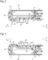
Fig. 2 is a cross-sectional view showing a first sealing member of the sealing device; -
Fig. 3 is a cross-sectional view showing a second sealing member of the sealing device; -
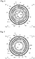
Fig. 4 is a view taken along line IV-IV inFig. 2 ; -
Fig. 5 is a view taken along line V-V inFig. 2 ; -
Fig. 6 is a view taken along line VI-VI inFigs. 4 and 5 showing a part of the sealing device; and -
Fig. 7 is a view taken along arrows VII-VII inFigs. 4 and 5 showing a part of the sealing device. - Hereinafter, with reference to the accompanying drawings, an embodiment according to the present invention will be described. It is noted that the drawings do not necessarily accurately show relative dimensional ratios of actual products according to the embodiments, and certain dimensions may be exaggerated.
- A sealing device according to the embodiment of the present invention is a two-liquid separation type that prevents mixing of two kinds of liquids. As shown in
Fig. 1 , a sealing device 1 according to the embodiment of the present invention is used for sealing a gap between arotational shaft 2 extending from the engine side to the transmission side and ahousing 4 for therotational shaft 2 in an automotive vehicle. Engine oil (liquid) is present on the engine side, whereas transmission oil or grease (liquid) is present on the transmission side. The sealing device 1 prevents mixing of the engine oil and the transmission oil or grease. - The
rotational shaft 2 has a cylindrical shape and the sealing device 1 has an annular shape, but only the left side parts of therotational shaft 2 and the sealing device 1 are shown inFig. 1 . - A shaft hole 6 is formed in the
housing 4, and therotational shaft 2 is disposed inside the shaft hole 6. Furthermore, one or more air passages 8 communicating with the shaft hole 6 are formed in thehousing 4. - The sealing device 1 includes an annular
first sealing member 10 and an annularsecond sealing member 12. Thefirst sealing member 10 and thesecond sealing member 12 are used in combination. Thefirst sealing member 10 and thesecond sealing member 12 are mounted on thehousing 4 in a combined state, so that the outer peripheral surface of therotational shaft 2 is in slidable contact with thefirst sealing member 10 and thesecond sealing member 12. In this embodiment, thefirst sealing member 10 and thesecond sealing member 12 have the same outer diameter and the same width (length in the axial direction of the rotational shaft 2). - The first sealing
member 10 is located on the engine side and can be called an engine-side sealing member. Thesecond sealing member 12 is located on the transmission side and can be referred to as a transmission-side sealing member. - The
first sealing member 10 has a composite structure including anelastic ring 14 and arigid ring 16. Theelastic ring 14 is made of an elastic material such as an elastomer. Therigid ring 16 is made of a rigid material, such as a metal. Therigid ring 16 is in close contact with theelastic ring 14 and reinforces theelastic ring 14. - The
first sealing member 10 has an outercylindrical part 18, an innercylindrical part 19, and a connectingpart 20. The innercylindrical part 19 is located radially inside the outercylindrical part 18, whereas the connectingpart 20 is a substantially circular plate that connects the outercylindrical part 18 with the innercylindrical part 19. - The outer
cylindrical part 18 is constituted of a part of theelastic ring 14 and a part of therigid ring 16 disposed inside thereof. The innercylindrical part 19 is constituted of a part of theelastic ring 14, whereas the connectingpart 20 is constituted of a part of theelastic ring 14 and a part of therigid ring 16. - The outer
cylindrical part 18 is a mounted part that is to be mounted on thehousing 4. Although the mounting scheme is not limited, the first sealingmember 10 can be fixed to thehousing 4, for example, by fitting (press-fitting) the outercylindrical part 18 into the shaft hole 6. - A
dust lip 22 and aseal lip 24 are formed on the innercylindrical part 19. Thedust lip 22 and theseal lip 24 are brought into contact with the outer peripheral surface of therotational shaft 2 and elastically deformed. However,Fig. 1 shows the contours of thedust lip 22 and theseal lip 24 that are not deformed. - The
dust lip 22 is a plate having a truncated cone shape, and the distal end thereof is in contact with the outer peripheral surface of therotational shaft 2. As therotational shaft 2 rotates, the outer peripheral surface of therotational shaft 2 slides on the distal end of thedust lip 22. Thedust lip 22 impedes or prevents foreign matter (for example, dust or muddy water) that has passed from the air passage 8 of thehousing 4 through aspace 25 between the first sealingmember 10 and the second sealingmember 12 from entering the engine side. - Although not essential, at least one
protrusion 26 is formed on the inner surface of thedust lip 22. Preferably,multiple protrusions 26 are formed on the inner surface of thedust lip 22 at, for example, equiangular intervals. When the pressure in aspace 27 between thedust lip 22 and theseal lip 24 decreases, and thus, thedust lip 22 is excessively elastically deformed and comes into close contact with the outer peripheral surface of therotational shaft 2, theprotrusions 26 interposed between thedust lip 22 and the outer peripheral surface ofrotational shaft 2 create one or more gaps between thedust lip 22 and theseal lip 24. As a result, thespace 27 and thespace 25 are temporarily communicated for eliminating an atmospheric pressure difference that causes theseal lip 24 to be brought into close contact with the outer peripheral surface of therotational shaft 2. In this way, theprotrusions 26 protect the sealinglip 24 from excessive wear. - The
seal lip 24 is a protrusion having a triangular cross section having two inclined surfaces, and the distal end thereof is in contact with the outer peripheral surface of therotational shaft 2. As therotational shaft 2 rotates, the outer peripheral surface of therotational shaft 2 slides on the distal end of theseal lip 24. Theseal lip 24 suppresses leakage of the engine oil from the engine side to the transmission side. - Although not essential, a
garter spring 28 may be wound around the innercylindrical part 19. Thegarter spring 28 presses theseal lip 24 inward to increase the contact pressure of theseal lip 24 against therotational shaft 2. - Although not essential, multiple spiral protrusions 30 and 32 are formed on the inclined surface of the
seal lip 24 on the side of thespace 27. - The interspace between the protrusions 30 and the interspace between the protrusions 32 serve to return the engine oil from the
space 27 to the engine side due to the relative rotation of theshaft 2 and thehousing 4. In other words, as theshaft 2 and thehousing 4 rotate relative to each other, the interspace between the protrusions 30 and the interspace between the protrusions 32 perform a pumping action that moves the engine oil from thespace 27 to the engine side. The protrusions 30 are adapted to the normal rotation direction, and the interspace between the protrusions 30 returns the engine oil from thespace 27 to the engine side during the relative normal rotation of theshaft 2 and thehousing 4. On the other hand, the protrusions 32 are adapted to the reverse rotation direction opposite to the normal rotation direction, and when theshaft 2 and thehousing 4 are rotated in the reverse direction, the interspace between the protrusions 32 returns the engine oil from thespace 27 to the engine side. - The connecting
part 20 is constituted of a part of theelastic ring 14 and a part of therigid ring 16. In the connectingpart 20, the part of theelastic ring 14 is disposed closer to the second sealingmember 12 than the part of therigid ring 16. One side of the connectingpart 20 closer to the second sealingmember 12 has twoflat surfaces rotational shaft 2 and are parallel to each other. The flat surfaces 34 and 36 face the second sealingmember 12. The radial innerflat surface 34 is farther from the second sealingmember 12 than the radially outerflat surface 36. That is, theflat surface 34 is recessed from theflat surface 36. - As shown in
Fig. 1 , and inFigs. 2 and4 showing only the first sealingmember 10, multiplefirst hooks 38 protrude from theflat surface 34 facing the second sealingmember 12. Eachfirst hook 38 has aproximal portion 38A protruding from theflat surface 34 and adistal portion 38B bent from theproximal portion 38A and oriented inward in a radial direction. As shown inFig. 4 , the multiplefirst hooks 38 have an arcuate outline and are arranged on the same circle at equiangular intervals in the circumferential direction. The multiplefirst hooks 38 have the same shape and the same dimensions as one another.Clearances 39 are provided between adjacentfirst hooks 38, and portions corresponding to theclearance 39 are flush with theflat surface 34. In this embodiment, fivefirst hooks 38 are formed, and fiveclearances 39 are provided. - Although not essential, a circular
circumferential groove 35 is formed on theflat surface 34. Thecircumferential groove 35 is located more on the radially inner side than the first hooks 38. - Multiple
first stoppers 40 protrude from theflat surface 36 facing the second sealingmember 12. Eachfirst stopper 40 is a flat plate, has an arcuate outline, and is arranged on the same circle at equiangular intervals in the circumferential direction. The multiplefirst stoppers 40 have the same shape and the same dimensions as one another.Clearances 41 are provided between adjacentfirst stoppers 40, and portions corresponding to theclearances 41 are flush with theflat surface 36. In this embodiment, twofirst stoppers 40 are formed, and twoclearances 41 are provided. - As shown in
Fig. 2 , the distal portions of thefirst stoppers 40 are flat surfaces perpendicular to the axial direction of therotation shaft 2 and parallel to theflat surfaces first stoppers 40 are flush with each other. - As shown in
Fig. 1 , the second sealingmember 12 is of a composite structure having anelastic ring 44 and arigid ring 46. Theelastic ring 44 is made of an elastic material such as an elastomer. Therigid ring 46 is made of a rigid material, such as a metal. Therigid ring 46 is in close contact with theelastic ring 44 and reinforces theelastic ring 44. - The
second sealing member 12 has an outercylindrical part 48, an innercylindrical part 49, and a connectingpart 50. The innercylindrical part 49 is located radially inside the outercylindrical part 48, whereas the connectingpart 50 is a substantially circular plate, and connects the outercylindrical part 48 with the innercylindrical part 49. - The outer
cylindrical part 48 is constituted of a part of theelastic ring 44 and a part of therigid ring 46 disposed inside thereof. The innercylindrical part 49 is constituted of a part of theelastic ring 44, whereas the connectingpart 50 is constituted of a part of theelastic ring 44 and a part of therigid ring 46. - The outer
cylindrical part 48 is a mounted part that is to be mounted on thehousing 4. Although the mounting scheme is not limited, the second sealingmember 12 can be fixed to thehousing 4, for example, by fitting (press-fitting) the outercylindrical part 48 into the shaft hole 6. - A
dust lip 52 and aseal lip 54 are formed on the innercylindrical part 49. Thedust lip 52 and theseal lip 54 are brought into contact with the outer peripheral surface of therotational shaft 2 and are elastically deformed. However,Fig. 1 shows the contours of thedust lip 52 andseal lip 54 that are not deformed. - The
dust lip 52 is a plate having a truncated cone shape, and the distal end thereof is in contact with the outer peripheral surface of therotational shaft 2. As therotational shaft 2 rotates, the outer peripheral surface of therotational shaft 2 slides on the distal end of thedust lip 52. Thedust lip 52 impedes or prevents foreign matter that has passed from the air passage 8 of thehousing 4 through thespace 25 between the first sealingmember 10 and the second sealingmember 12 from entering the transmission side. - Although not essential, at least one
protrusion 56 is formed on the inner surface of thedust lip 52. Preferably,multiple protrusions 56 are formed on the inner surface of thedust lip 52 at, for example, equiangular intervals. When the pressure in aspace 57 between thedust lip 52 and theseal lip 54 decreases, and thus, thedust lip 52 is excessively elastically deformed and comes into close contact with the outer peripheral surface of therotational shaft 2, theprotrusions 56 interposed between thedust lip 52 and the outer peripheral surface of therotational shaft 2 create one or more gaps between thedust lip 52 and theseal lip 54. As a result, thespace 57 and thespace 25 are temporarily communicated for eliminating an atmospheric pressure difference that causes theseal lip 54 to be brought into close contact with the outer peripheral surface of therotational shaft 2. In this way, theprotrusions 56 protect theseal lip 54 from excessive wear. - The
seal lip 54 is a protrusion having a triangular cross section having two inclined surfaces, and the distal end thereof is in contact with the outer peripheral surface of therotational shaft 2. As therotational shaft 2 rotates, the outer peripheral surface of therotational shaft 2 slides on the distal end of theseal lip 54. Theseal lip 54 suppresses leakage of the transmission oil or grease from the transmission side to the engine side. - Although not essential, a
garter spring 58 may be wound around the innercylindrical part 49. Thegarter spring 58 presses theseal lip 54 inward to increase the contact pressure of theseal lip 54 against therotational shaft 2. - Although not essential, multiple
spiral protrusions seal lip 54 on the side of thespace 57. - The interspace between the
protrusions 60 and the interspace between theprotrusions 62 serve to return the transmission oil or grease from thespace 57 to the transmission side due to the relative rotation of theshaft 2 and thehousing 4. In other words, as theshaft 2 and thehousing 4 rotate relative to each other, the interspace between theprotrusions 60 and the interspace between theprotrusions 62 perform a pumping action that moves the transmission oil or grease from thespace 57 to the transmission side. Theprotrusions 62 are adapted to the normal rotation direction, and the interspace between theprotrusions 62 returns the transmission oil or grease from thespace 57 to the transmission side during the relative normal rotation of theshaft 2 and thehousing 4. On the other hand, theprotrusions 60 are adapted to the reverse rotation direction opposite to the normal rotation direction, and when theshaft 2 and thehousing 4 are rotated in the reverse direction, the interspace between theprotrusions 60 returns the transmission oil or grease from thespace 57 to the transmission side. - The connecting
part 50 is constituted of a part of theelastic ring 44 and a part of therigid ring 46. In the connectingpart 50, the part of theelastic ring 44 is disposed closer to the first sealingmember 10 than the part of therigid ring 46. One side of the connectingpart 50 closer to the first sealingmember 10 has twoflat surfaces rotational shaft 2 and are parallel to each other. The flat surfaces 64 and 66 face the first sealingmember 10. The radial innerflat surface 64 is farther from the first sealingmember 10 than the radially outerflat surface 66. That is, theflat surface 64 is recessed from theflat surface 66. - As shown in
Fig. 1 , and inFig. 3 and5 showing only the second sealingmember 12, multiplesecond hooks 68 protrude from theflat surface 64 facing the first sealingmember 10. Eachsecond hook 68 has aproximal portion 68A protruding from theflat surface 64 and adistal portion 68B bent from theproximal portion 68A and oriented outward in a radial direction. As shown inFig. 5 , the multiplesecond hooks 68 have an arcuate outline and are arranged on the same circle at equiangular intervals in the circumferential direction. The multiplesecond hooks 68 have the same shape and the same dimensions as one another.Clearances 69 are provided between adjacentsecond hooks 68, and portions corresponding to theclearances 69 are flush with theflat surface 64. In this embodiment, threesecond hooks 68 are formed, and threeclearances 69 are provided. - Although not essential, a circular
circumferential groove 65 is formed on theflat surface 64. Thecircumferential groove 65 is located more on the radially outer side than the second hooks 68. - Multiple
second stoppers 70 protrude from theflat surface 66 facing the first sealingmember 10. Eachsecond stopper 70 is a flat plate, has an arcuate outline, and is arranged on the same circle at equiangular intervals in the circumferential direction. The multiplesecond stoppers 70 have the same shape and the same dimensions as one another.Clearances 71 are provided between adjacentsecond stoppers 70, and portions corresponding to theclearances 71 are flush with theflat surface 66. In this embodiment, twosecond stoppers 70 are formed, and twoclearances 71 are provided. - As shown in
Fig. 3 , the distal portions of each of thesecond stoppers 70 are flat surfaces perpendicular to the axial direction of therotation shaft 2 and parallel to theflat surfaces second stoppers 70 are flush with each other. - As shown in
Fig. 1 , thedistal portions 68B of thesecond hooks 68 are hooked on thedistal portions 38B of thefirst hook 38, thereby restricting the movement toward the direction in which the first sealingmember 10 and the second sealingmember 12 are separated from each other. Thus, once the first sealingmember 10 and the second sealingmember 12 are combined with each other, the first sealingmember 10 and the second sealingmember 12 are difficult to separate from each other. Therefore, it is possible to handle the first sealingmember 10 and the second sealingmember 12 as a single sealing device 1 as an assembly, so that, for example, it is easy to attach the sealing device 1 to a desired position between therotational shaft 2 and thehousing 4. For example, the step of press-fitting the outercylindrical part 18 into the shaft hole 6 and the step of press-fitting the outercylindrical part 48 into the shaft hole 6 can be performed in one step. Since thehooks - Furthermore, the flat distal portions of the multiple
second stoppers 70 are brought into contact with the flat distal portions of the multiplefirst stoppers 40, thereby restricting the movement toward the direction in which the first sealingmember 10 and the second sealingmember 12 approach each other. It is possible to appropriately maintain the interval between the first sealing member 10 (and thedust lip 22 and theseal lip 24 that are elements of the first sealing member 10) and the second sealing member 12 (and thedust lip 52 and the sealinglip 54 that are elements of the second sealing member 12) in the axial direction of the sealing device 1. In other words, thestoppers member 10 and the second sealingmember 12 relative to each other. - In this embodiment, the
first stoppers 40 and thesecond stoppers 70 are less likely to deform than thefirst hooks 38 and the second hooks 68. Specifically, the width of each of thestoppers 40 and 70 (length in radial directions of the sealing device 1) is greater than the width of each of theproximal portions hooks 38 and 68 (length in radial directions of the sealing device 1). The length of each of thestoppers hooks stoppers 40 and 70 (length in the axial direction of the sealing device 1) is less than the height of each of thehooks 38 and 68 (length in the axial direction of the sealing device 1). - Since the
stoppers hooks first hooks 38 and thesecond hooks 68 and mainly depends on the degree of deformation of thefirst stoppers 40 and thesecond stoppers 70. Therefore, it is easy to design the interval between the sealingmembers - In this embodiment, as shown in
Fig. 1 , when the distal portions of thesecond stoppers 70 are in contact with the distal portions of thefirst stoppers 40, there are clearances between thefirst hooks 38 and the second hooks 68, between eachfirst hook 38 and theflat surface 64 of the second sealingmember 12, and between eachsecond hook 68 and theflat surface 34 of the first sealingmember 10. In other words, when the distal portions of thesecond stoppers 70 are in contact with the distal portions of thefirst stoppers 40, thefirst hooks 38 are not in contact with the second sealingmember 12, and thesecond hook 68 are not also in contact with the first sealingmember 10. - Thus, the interval between the first sealing member 10 (and elements of the first sealing member 10) and the second sealing member 12 (and elements of the second sealing member 12) in the axial direction is unlikely to be affected by the degree of hooking between the
first hooks 38 and thesecond hooks 68 and mainly depends on the degree of deformation of thefirst stoppers 40 and thesecond stoppers 70. Therefore, it is easy to design the interval between the sealingmembers - In such a sealing device 1 in which the sealing
members dust lip 22 and the seal lip 24) and elements of the second sealing member 12 (thedust lip 52 and the seal lip 54) due to change in atmospheric pressure in thespace 25 between the sealingmembers space 25 to the outside and be able to flow into thespace 25 from the outside due to change in atmospheric pressure in thespace 25. For this purpose, one or more air passages 8, which communicate with thespace 25, are formed in thehousing 4. - However, when air flows into the
space 25 from the outside and advances radially inward, it is desirable that foreign matter not reach the sealed part between any one of the sealingmembers rotational shaft 2. This is because if foreign matter intrudes between any one of the lips and therotational shaft 2, it is likely that sealed liquid may leak out. - Accordingly, as shown in
Fig. 4 , in the first sealingmember 10, theclearances 39 between thefirst hooks 38 are arranged such that theclearances 39 do not overlap with theclearance 41 between thefirst stoppers 40 in radial directions, so that foreign matter is unlikely to reach the sealed part between any one of the sealingmembers rotational shaft 2. In addition, as shown inFig. 5 , in the second sealingmember 12, theclearances 69 between thesecond hooks 68 are arranged such that theclearances 69 do not overlap with theclearances 71 between thesecond stoppers 70 in radial directions, so that foreign matter is unlikely to reach the sealed part between any one of the sealingmembers rotational shaft 2. - In
Figs. 4 and 5 , multiple arrows schematically indicate paths through which inflow air from the air passage 8 travels radially inward. As shown in the figures, bent paths produced by the hooks and the stoppers are provided. It will be understood that foreign matter is unlikely to reach the sealed part between any one of the sealingmembers rotational shaft 2. - In this embodiment, the number of the
first hooks 38 and the number of thesecond hooks 68 are different. The number of the first hooks 38 is five, whereas the number of the second hooks 68 is three. Therefore, it is unlikely that theclearances 39 between thefirst hooks 38 overlap with theclearances 69 between thesecond hooks 68 in the radial directions, and foreign matter is more unlikely to reach the sealed part between any one of the sealingmembers rotational shaft 2. -
Fig. 6 is a view of the combined sealingmembers Figs. 4 and 5 .Fig. 7 is a view of the combined sealingmembers Figs. 4 and 5 . InFigs. 6 and 7 , the oblique lines extending from the upper left to the lower right represent the areas of thefirst hooks 38, whereas the oblique lines extending from the upper right to the lower left represent the areas of the second hooks 68. - As shown in
Figs. 6 and 7 , there is a region where theclearance 39 between thefirst hooks 38 overlaps with theclearance 69 between the second hooks 68 (region without hatching), but there are also regions where theclearances 39 between thefirst hooks 38 do not overlap with theclearances 69 between the second hooks 68 (regions having only one type of diagonal lines). Thus, since the number of thefirst hooks 38 arranged at equiangular intervals is different from the number of thesecond hooks 68 arranged at equiangular intervals, the possibility that theclearances 39 overlap with theclearances 69 in radial directions is low. - Although an embodiment of the present invention has been described, the foregoing description is not intended to limit the present invention, and various modifications including omission, addition, and substitution of structural elements may be made within the scope of the present invention.
- For example, in the above-described embodiment, the
dust lips members dust lips - In the above-described embodiment, the first sealing
member 10 and the second sealingmember 12 have the same outer diameter and the same width, and have thesame lips member 10 and the second sealingmember 12 may have different dimensions and may have lips of different sizes. - In the above-described embodiment, the
first hooks 38 of the first sealingmember 10 are located radially outside thesecond hook 68 of the second sealingmember 12, but thefirst hook 38 may be located radially inside the second hooks 68. - In the above-described embodiment, the first sealing
member 10 is disposed on the engine side and the second sealingmember 12 is disposed on the transmission side, but the reverse arrangement may be employed. - In the above-described embodiment, the number of the first hooks 38 is five, whereas the number of the second hooks 68 is three. However, the number of the first hooks 38 is not limited, and the number of the second hooks 68 is not limited. The number of
first hooks 38 may be the same as the number of second hooks 68. - In the above-described embodiment, the number of the
first stoppers 40 is two, whereas the number of thesecond stoppers 70 is also two. However, the number of thefirst stoppers 40 is not limited, and the number of thesecond stoppers 70 is not limited. The number offirst stoppers 40 may be the same as the number of first hooks 38. The number ofsecond stoppers 70 may also be the same as the number of second hooks 68. - In the above-described embodiment, the
first hooks 38 are arranged at equiangular intervals, and thesecond hooks 68 are arranged at equiangular intervals. Thefirst stoppers 40 are arranged at equiangular intervals, and thesecond stoppers 70 are arranged at equiangular intervals. However, they do not necessarily have to be arranged at equiangular intervals. It is also possible to prevent theclearances 39 from overlapping theclearances 69 at all by changing the numbers and intervals of the hooks. - In the above-described embodiment, the flat distal portions of the multiple
first stoppers 40 are flush with each other, whereas the flat distal portions of the multiplesecond stoppers 70 are flush with each other. However, the flat distal portions of the multiplefirst stoppers 40 may have a step, and the flat distal portions of the multiplesecond stoppers 70 may also have a step. The distal portions of thestoppers - In the above-described embodiment, the sealing device 1 is used for sealing a gap between the
rotational shaft 2 extending from the engine side to the transmission side and thehousing 4 for therotational shaft 2 in an automotive vehicle, for preventing mixing of the engine oil with the transmission oil or grease. However, the use of the sealing device according to the present invention is not limited to the embodiment, and the sealing device according to the present invention may be widely used in order to prevent mixing of two kinds of sealed liquids. For example, the sealing device according to the present invention may be used for the purpose of preventing mixing of water and oil. -
- 1: Sealing Device
- 2: Rotational Shaft
- 4: Housing
- 6: Shaft Hole
- 8: Air Passage
- 10: First Sealing Member
- 12: Second Sealing Member
- 14, 44: Elastic Ring
- 16, 46: Rigid Ring
- 22, 52: Dust Lip
- 24, 54: Seal Lip
- 25: Space
- 27, 57: Space
- 34, 36, 64, 66: Flat Surface
- 38: First Hook
- 68: Second Hook
- 38A, 68A: Proximal Portion
- 38B, 68B: Distal Portion
- 39, 69: Clearance
- 40: First Stopper
- 70: Second Stopper
- 41, 71: Clearance
Claims (6)
- A sealing device for sealing a gap between a rotational shaft and a housing for the rotational shaft, including:a first sealing member mounted on the housing, an outer peripheral surface of the rotational shaft being in slidable contact with the first sealing member; anda second sealing member mounted on the housing, the outer peripheral surface of the rotational shaft being in slidable contact with the second sealing member,the first sealing member comprising multiple first hooks projecting from a surface thereof facing the second sealing member, each first hook comprising a proximal portion and a distal portion bent from the proximal portion and oriented in a radial direction of the sealing device,the second sealing member comprising multiple second hooks projecting from a surface thereof facing the first sealing member, each second hook comprising a proximal portion and a distal portion bent from the proximal portion and oriented in a radial direction of the sealing device,the distal portion of each second hook being hooked on the distal portion of a first hook for restricting movement of the second sealing member away from the first sealing member in an axial direction of the sealing device,the first sealing member comprising multiple first stoppers projecting from the surface thereof facing the second sealing member,the second sealing member comprising multiple second stoppers projecting from the surface thereof facing the first sealing member,a distal portion of each second stopper being in contact with a distal portion of a first stopper for restricting movement of the second sealing member toward the first sealing member in the axial direction.
- The sealing device according to claim 1, wherein the first stoppers and the second stoppers are less likely to deform than the first hooks and the second hooks.
- The sealing device according to claim 1 or 2, wherein when the distal portions of the second stoppers are in contact with the distal portions of the first stoppers, there are clearances between the first hooks and the second hooks.
- The sealing device according to any one of claims 1-3, wherein the multiple first hooks are arranged at intervals in a circumferential direction, the multiple first stoppers being arranged at intervals in a circumferential direction,
clearances between the first hooks not overlapping with clearances between the first stoppers in radial directions of the sealing device. - The sealing device according to any one of claims 1-4, wherein the multiple second hooks are arranged at intervals in a circumferential direction, the multiple second stoppers being arranged at intervals in a circumferential direction,
clearances between the second hooks not overlapping with clearances between the second stoppers in radial directions of the sealing device. - The sealing device according to claim 4 or 5, wherein the multiple first hooks are arranged at equiangular intervals in the circumferential direction, the multiple second hooks being arranged at equiangular intervals in the circumferential direction, the number of the first hooks and the number of the second hooks being different from each other.
Applications Claiming Priority (2)
| Application Number | Priority Date | Filing Date | Title |
|---|---|---|---|
| JP2018134588 | 2018-07-17 | ||
| PCT/JP2019/025059 WO2020017249A1 (en) | 2018-07-17 | 2019-06-25 | Sealing device |
Publications (4)
| Publication Number | Publication Date |
|---|---|
| EP3825586A1 true EP3825586A1 (en) | 2021-05-26 |
| EP3825586A4 EP3825586A4 (en) | 2021-09-08 |
| EP3825586C0 EP3825586C0 (en) | 2025-01-29 |
| EP3825586B1 EP3825586B1 (en) | 2025-01-29 |
Family
ID=69164678
Family Applications (1)
| Application Number | Title | Priority Date | Filing Date |
|---|---|---|---|
| EP19837054.6A Active EP3825586B1 (en) | 2018-07-17 | 2019-06-25 | Sealing device |
Country Status (5)
| Country | Link |
|---|---|
| US (1) | US11493132B2 (en) |
| EP (1) | EP3825586B1 (en) |
| JP (1) | JP6814911B2 (en) |
| CN (1) | CN112074676B (en) |
| WO (1) | WO2020017249A1 (en) |
Family Cites Families (18)
| Publication number | Priority date | Publication date | Assignee | Title |
|---|---|---|---|---|
| JPS6119241Y2 (en) | 1979-08-07 | 1986-06-10 | ||
| JPS6119241U (en) | 1984-07-10 | 1986-02-04 | 日本電産コパル株式会社 | Roll photographic paper guide mechanism |
| JPH0446139Y2 (en) | 1985-09-06 | 1992-10-29 | ||
| JPH0311175U (en) | 1989-06-20 | 1991-02-04 | ||
| JPH0630567U (en) | 1992-09-24 | 1994-04-22 | エヌオーケー株式会社 | Oil seal |
| IT1276368B1 (en) * | 1995-06-09 | 1997-10-31 | Stefa S R L | LIP SEALING COMPLEX. |
| JP2003083456A (en) | 2001-09-10 | 2003-03-19 | Kawasaki Steel Corp | Bearing sealing device |
| JP2005172061A (en) * | 2003-12-09 | 2005-06-30 | Nok Corp | Sealing device |
| DE102004002978A1 (en) | 2004-01-21 | 2005-08-18 | Carl Freudenberg Kg | Radial shaft seal |
| US7775528B2 (en) * | 2006-02-13 | 2010-08-17 | Freudenberg-Nok General Partnership | Bi-directional pattern for dynamic seals |
| CN201187581Y (en) * | 2008-03-20 | 2009-01-28 | 青岛开世密封工业有限公司 | Combined two-sided oil seal |
| EP2278196A1 (en) | 2009-07-22 | 2011-01-26 | Carl Freudenberg KG | Sealing ring and corresponding sealing assembly |
| US20120313329A1 (en) * | 2011-06-10 | 2012-12-13 | Freudenberg-Nok General Partnership | Vented Dual Lip Seal And Method Of Making |
| JP6138545B2 (en) | 2013-03-29 | 2017-05-31 | キーパー株式会社 | Oil seal |
| CN203146822U (en) * | 2013-04-07 | 2013-08-21 | 艾志(南京)环保管接技术股份有限公司 | Multi-ring lip line sealed bearing protector |
| DE102013010926A1 (en) * | 2013-06-29 | 2014-12-31 | Geräte- und Pumpenbau GmbH Dr. Eugen Schmidt | Radial shaft seal |
| CN203604656U (en) * | 2013-11-26 | 2014-05-21 | 青岛开世密封工业有限公司 | Back-to-back combined oil seal |
| CN206555445U (en) * | 2017-03-06 | 2017-10-13 | 广州流体密封科技有限公司 | A kind of rotating seal component |
-
2019
- 2019-06-25 US US17/041,105 patent/US11493132B2/en active Active
- 2019-06-25 EP EP19837054.6A patent/EP3825586B1/en active Active
- 2019-06-25 WO PCT/JP2019/025059 patent/WO2020017249A1/en not_active Ceased
- 2019-06-25 CN CN201980029419.0A patent/CN112074676B/en active Active
- 2019-06-25 JP JP2020531199A patent/JP6814911B2/en active Active
Also Published As
| Publication number | Publication date |
|---|---|
| CN112074676B (en) | 2022-12-23 |
| JP6814911B2 (en) | 2021-01-20 |
| EP3825586C0 (en) | 2025-01-29 |
| WO2020017249A1 (en) | 2020-01-23 |
| EP3825586A4 (en) | 2021-09-08 |
| JPWO2020017249A1 (en) | 2021-01-07 |
| EP3825586B1 (en) | 2025-01-29 |
| CN112074676A (en) | 2020-12-11 |
| US20210102628A1 (en) | 2021-04-08 |
| US11493132B2 (en) | 2022-11-08 |
Similar Documents
| Publication | Publication Date | Title |
|---|---|---|
| JP6445085B2 (en) | Sealing device | |
| EP2913566B1 (en) | Oil seal | |
| US20130087978A1 (en) | Sealing device | |
| JP5141930B2 (en) | Sealing device | |
| EP2619488B1 (en) | Fluid seal assembly | |
| CN109642675B (en) | Sealing means | |
| US5597168A (en) | Single split oil seal | |
| CN114635915B (en) | Sealing device | |
| EP3845781A1 (en) | Sealing device | |
| US9850949B2 (en) | Temperature compensation ring, bearing ring, and bearing assembly | |
| EP3385578B1 (en) | Sealing device | |
| US20160116067A1 (en) | Sealing device | |
| JP2001263499A (en) | Lip type seal | |
| US9841105B2 (en) | Sealing lip and seal | |
| US9869393B2 (en) | Shaft seal, especially radial shaft seal | |
| KR20140137408A (en) | Radial shaft seal with static and hydrodynamic sealing features | |
| CN111237467B (en) | Especially for sealing devices of engine shafts | |
| EP3825586B1 (en) | Sealing device | |
| CN110073131A (en) | Sealing device | |
| JP2010060120A (en) | Sealing device | |
| JP4609636B2 (en) | Sealing device | |
| CN113494609A (en) | Sealing ring | |
| JP7372779B2 (en) | sealing device | |
| CN112204278A (en) | Sealing device | |
| JPH0559056U (en) | Oil seal |
Legal Events
| Date | Code | Title | Description |
|---|---|---|---|
| STAA | Information on the status of an ep patent application or granted ep patent |
Free format text: STATUS: THE INTERNATIONAL PUBLICATION HAS BEEN MADE |
|
| PUAI | Public reference made under article 153(3) epc to a published international application that has entered the european phase |
Free format text: ORIGINAL CODE: 0009012 |
|
| STAA | Information on the status of an ep patent application or granted ep patent |
Free format text: STATUS: REQUEST FOR EXAMINATION WAS MADE |
|
| 17P | Request for examination filed |
Effective date: 20200916 |
|
| AK | Designated contracting states |
Kind code of ref document: A1 Designated state(s): AL AT BE BG CH CY CZ DE DK EE ES FI FR GB GR HR HU IE IS IT LI LT LU LV MC MK MT NL NO PL PT RO RS SE SI SK SM TR |
|
| A4 | Supplementary search report drawn up and despatched |
Effective date: 20210806 |
|
| RIC1 | Information provided on ipc code assigned before grant |
Ipc: F16J 15/3244 20160101ALI20210802BHEP Ipc: F16J 15/3268 20160101ALI20210802BHEP Ipc: F16J 15/3204 20160101AFI20210802BHEP |
|
| DAV | Request for validation of the european patent (deleted) | ||
| DAX | Request for extension of the european patent (deleted) | ||
| STAA | Information on the status of an ep patent application or granted ep patent |
Free format text: STATUS: EXAMINATION IS IN PROGRESS |
|
| 17Q | First examination report despatched |
Effective date: 20230109 |
|
| GRAP | Despatch of communication of intention to grant a patent |
Free format text: ORIGINAL CODE: EPIDOSNIGR1 |
|
| STAA | Information on the status of an ep patent application or granted ep patent |
Free format text: STATUS: GRANT OF PATENT IS INTENDED |
|
| INTG | Intention to grant announced |
Effective date: 20240716 |
|
| RIN1 | Information on inventor provided before grant (corrected) |
Inventor name: SYONAI, MASARU |
|
| GRAJ | Information related to disapproval of communication of intention to grant by the applicant or resumption of examination proceedings by the epo deleted |
Free format text: ORIGINAL CODE: EPIDOSDIGR1 |
|
| STAA | Information on the status of an ep patent application or granted ep patent |
Free format text: STATUS: EXAMINATION IS IN PROGRESS |
|
| GRAP | Despatch of communication of intention to grant a patent |
Free format text: ORIGINAL CODE: EPIDOSNIGR1 |
|
| STAA | Information on the status of an ep patent application or granted ep patent |
Free format text: STATUS: GRANT OF PATENT IS INTENDED |
|
| INTC | Intention to grant announced (deleted) | ||
| INTG | Intention to grant announced |
Effective date: 20241029 |
|
| GRAS | Grant fee paid |
Free format text: ORIGINAL CODE: EPIDOSNIGR3 |
|
| GRAA | (expected) grant |
Free format text: ORIGINAL CODE: 0009210 |
|
| STAA | Information on the status of an ep patent application or granted ep patent |
Free format text: STATUS: THE PATENT HAS BEEN GRANTED |
|
| AK | Designated contracting states |
Kind code of ref document: B1 Designated state(s): AL AT BE BG CH CY CZ DE DK EE ES FI FR GB GR HR HU IE IS IT LI LT LU LV MC MK MT NL NO PL PT RO RS SE SI SK SM TR |
|
| REG | Reference to a national code |
Ref country code: GB Ref legal event code: FG4D |
|
| REG | Reference to a national code |
Ref country code: CH Ref legal event code: EP |
|
| REG | Reference to a national code |
Ref country code: DE Ref legal event code: R096 Ref document number: 602019065472 Country of ref document: DE |
|
| REG | Reference to a national code |
Ref country code: IE Ref legal event code: FG4D |
|
| U01 | Request for unitary effect filed |
Effective date: 20250207 |
|
| U07 | Unitary effect registered |
Designated state(s): AT BE BG DE DK EE FI FR IT LT LU LV MT NL PT RO SE SI Effective date: 20250213 |
|
| PG25 | Lapsed in a contracting state [announced via postgrant information from national office to epo] |
Ref country code: RS Free format text: LAPSE BECAUSE OF FAILURE TO SUBMIT A TRANSLATION OF THE DESCRIPTION OR TO PAY THE FEE WITHIN THE PRESCRIBED TIME-LIMIT Effective date: 20250429 |
|
| PG25 | Lapsed in a contracting state [announced via postgrant information from national office to epo] |
Ref country code: PL Free format text: LAPSE BECAUSE OF FAILURE TO SUBMIT A TRANSLATION OF THE DESCRIPTION OR TO PAY THE FEE WITHIN THE PRESCRIBED TIME-LIMIT Effective date: 20250129 |
|
| PG25 | Lapsed in a contracting state [announced via postgrant information from national office to epo] |
Ref country code: ES Free format text: LAPSE BECAUSE OF FAILURE TO SUBMIT A TRANSLATION OF THE DESCRIPTION OR TO PAY THE FEE WITHIN THE PRESCRIBED TIME-LIMIT Effective date: 20250129 |
|
| PG25 | Lapsed in a contracting state [announced via postgrant information from national office to epo] |
Ref country code: IS Free format text: LAPSE BECAUSE OF FAILURE TO SUBMIT A TRANSLATION OF THE DESCRIPTION OR TO PAY THE FEE WITHIN THE PRESCRIBED TIME-LIMIT Effective date: 20250529 Ref country code: NO Free format text: LAPSE BECAUSE OF FAILURE TO SUBMIT A TRANSLATION OF THE DESCRIPTION OR TO PAY THE FEE WITHIN THE PRESCRIBED TIME-LIMIT Effective date: 20250429 |
|
| PG25 | Lapsed in a contracting state [announced via postgrant information from national office to epo] |
Ref country code: HR Free format text: LAPSE BECAUSE OF FAILURE TO SUBMIT A TRANSLATION OF THE DESCRIPTION OR TO PAY THE FEE WITHIN THE PRESCRIBED TIME-LIMIT Effective date: 20250129 |
|
| PG25 | Lapsed in a contracting state [announced via postgrant information from national office to epo] |
Ref country code: GR Free format text: LAPSE BECAUSE OF FAILURE TO SUBMIT A TRANSLATION OF THE DESCRIPTION OR TO PAY THE FEE WITHIN THE PRESCRIBED TIME-LIMIT Effective date: 20250430 |
|
| U20 | Renewal fee for the european patent with unitary effect paid |
Year of fee payment: 7 Effective date: 20250623 |
|
| PG25 | Lapsed in a contracting state [announced via postgrant information from national office to epo] |
Ref country code: SM Free format text: LAPSE BECAUSE OF FAILURE TO SUBMIT A TRANSLATION OF THE DESCRIPTION OR TO PAY THE FEE WITHIN THE PRESCRIBED TIME-LIMIT Effective date: 20250129 |
|
| PG25 | Lapsed in a contracting state [announced via postgrant information from national office to epo] |
Ref country code: CZ Free format text: LAPSE BECAUSE OF FAILURE TO SUBMIT A TRANSLATION OF THE DESCRIPTION OR TO PAY THE FEE WITHIN THE PRESCRIBED TIME-LIMIT Effective date: 20250129 |
|
| PG25 | Lapsed in a contracting state [announced via postgrant information from national office to epo] |
Ref country code: SK Free format text: LAPSE BECAUSE OF FAILURE TO SUBMIT A TRANSLATION OF THE DESCRIPTION OR TO PAY THE FEE WITHIN THE PRESCRIBED TIME-LIMIT Effective date: 20250129 |
|
| PLBE | No opposition filed within time limit |
Free format text: ORIGINAL CODE: 0009261 |
|
| STAA | Information on the status of an ep patent application or granted ep patent |
Free format text: STATUS: NO OPPOSITION FILED WITHIN TIME LIMIT |
|
| REG | Reference to a national code |
Ref country code: CH Ref legal event code: L10 Free format text: ST27 STATUS EVENT CODE: U-0-0-L10-L00 (AS PROVIDED BY THE NATIONAL OFFICE) Effective date: 20251210 |
|
| 26N | No opposition filed |
Effective date: 20251030 |
|
| REG | Reference to a national code |
Ref country code: CH Ref legal event code: H13 Free format text: ST27 STATUS EVENT CODE: U-0-0-H10-H13 (AS PROVIDED BY THE NATIONAL OFFICE) Effective date: 20260127 |
|
| PG25 | Lapsed in a contracting state [announced via postgrant information from national office to epo] |
Ref country code: MC Free format text: LAPSE BECAUSE OF FAILURE TO SUBMIT A TRANSLATION OF THE DESCRIPTION OR TO PAY THE FEE WITHIN THE PRESCRIBED TIME-LIMIT Effective date: 20250129 |
|
| GBPC | Gb: european patent ceased through non-payment of renewal fee |
Effective date: 20250625 |
|
| PG25 | Lapsed in a contracting state [announced via postgrant information from national office to epo] |
Ref country code: GB Free format text: LAPSE BECAUSE OF NON-PAYMENT OF DUE FEES Effective date: 20250625 |
|
| PG25 | Lapsed in a contracting state [announced via postgrant information from national office to epo] |
Ref country code: IE Free format text: LAPSE BECAUSE OF NON-PAYMENT OF DUE FEES Effective date: 20250625 |
|
| PG25 | Lapsed in a contracting state [announced via postgrant information from national office to epo] |
Ref country code: CH Free format text: LAPSE BECAUSE OF NON-PAYMENT OF DUE FEES Effective date: 20250630 |