EP3825571A1 - Spring element - Google Patents
Spring element Download PDFInfo
- Publication number
- EP3825571A1 EP3825571A1 EP20198824.3A EP20198824A EP3825571A1 EP 3825571 A1 EP3825571 A1 EP 3825571A1 EP 20198824 A EP20198824 A EP 20198824A EP 3825571 A1 EP3825571 A1 EP 3825571A1
- Authority
- EP
- European Patent Office
- Prior art keywords
- spring
- spring element
- fastening
- limiting
- sleeve
- Prior art date
- Legal status (The legal status is an assumption and is not a legal conclusion. Google has not performed a legal analysis and makes no representation as to the accuracy of the status listed.)
- Pending
Links
- 238000002955 isolation Methods 0.000 claims abstract description 13
- 238000005520 cutting process Methods 0.000 claims description 13
- 238000006073 displacement reaction Methods 0.000 claims description 9
- 239000000463 material Substances 0.000 claims description 9
- 238000005452 bending Methods 0.000 claims description 7
- 230000002238 attenuated effect Effects 0.000 claims description 3
- 239000000203 mixture Substances 0.000 claims 1
- 238000004519 manufacturing process Methods 0.000 description 10
- 230000007704 transition Effects 0.000 description 8
- 230000006835 compression Effects 0.000 description 5
- 238000007906 compression Methods 0.000 description 5
- 229910000831 Steel Inorganic materials 0.000 description 4
- 230000007246 mechanism Effects 0.000 description 4
- 239000010959 steel Substances 0.000 description 4
- 230000007423 decrease Effects 0.000 description 3
- 239000004033 plastic Substances 0.000 description 3
- 229920003023 plastic Polymers 0.000 description 3
- 238000003466 welding Methods 0.000 description 3
- 238000009826 distribution Methods 0.000 description 2
- 239000013013 elastic material Substances 0.000 description 2
- 229920001971 elastomer Polymers 0.000 description 2
- 230000010354 integration Effects 0.000 description 2
- 230000003068 static effect Effects 0.000 description 2
- 229920000049 Carbon (fiber) Polymers 0.000 description 1
- 239000004952 Polyamide Substances 0.000 description 1
- 239000004698 Polyethylene Substances 0.000 description 1
- 239000004743 Polypropylene Substances 0.000 description 1
- RTAQQCXQSZGOHL-UHFFFAOYSA-N Titanium Chemical compound [Ti] RTAQQCXQSZGOHL-UHFFFAOYSA-N 0.000 description 1
- 239000004676 acrylonitrile butadiene styrene Substances 0.000 description 1
- 229920000122 acrylonitrile butadiene styrene Polymers 0.000 description 1
- 239000000956 alloy Substances 0.000 description 1
- 229910045601 alloy Inorganic materials 0.000 description 1
- 239000004411 aluminium Substances 0.000 description 1
- 229910052782 aluminium Inorganic materials 0.000 description 1
- XAGFODPZIPBFFR-UHFFFAOYSA-N aluminium Chemical compound [Al] XAGFODPZIPBFFR-UHFFFAOYSA-N 0.000 description 1
- 230000008901 benefit Effects 0.000 description 1
- 239000004917 carbon fiber Substances 0.000 description 1
- 238000005266 casting Methods 0.000 description 1
- 230000008859 change Effects 0.000 description 1
- 238000005097 cold rolling Methods 0.000 description 1
- 238000010276 construction Methods 0.000 description 1
- 230000001419 dependent effect Effects 0.000 description 1
- 239000000806 elastomer Substances 0.000 description 1
- 238000005516 engineering process Methods 0.000 description 1
- 230000007613 environmental effect Effects 0.000 description 1
- 239000011152 fibreglass Substances 0.000 description 1
- 238000005098 hot rolling Methods 0.000 description 1
- 238000005259 measurement Methods 0.000 description 1
- 239000007769 metal material Substances 0.000 description 1
- VNWKTOKETHGBQD-UHFFFAOYSA-N methane Chemical compound C VNWKTOKETHGBQD-UHFFFAOYSA-N 0.000 description 1
- 238000000034 method Methods 0.000 description 1
- 229920002647 polyamide Polymers 0.000 description 1
- 229920000515 polycarbonate Polymers 0.000 description 1
- 239000004417 polycarbonate Substances 0.000 description 1
- -1 polyethylene Polymers 0.000 description 1
- 229920000573 polyethylene Polymers 0.000 description 1
- 229920001155 polypropylene Polymers 0.000 description 1
- 230000008569 process Effects 0.000 description 1
- 230000009467 reduction Effects 0.000 description 1
- 239000002990 reinforced plastic Substances 0.000 description 1
- 238000005096 rolling process Methods 0.000 description 1
- 239000005060 rubber Substances 0.000 description 1
- 238000004381 surface treatment Methods 0.000 description 1
- 239000010936 titanium Substances 0.000 description 1
- 229910052719 titanium Inorganic materials 0.000 description 1
- 230000009466 transformation Effects 0.000 description 1
- 238000000844 transformation Methods 0.000 description 1
- XLYOFNOQVPJJNP-UHFFFAOYSA-N water Substances O XLYOFNOQVPJJNP-UHFFFAOYSA-N 0.000 description 1
Images



Classifications
-
- F—MECHANICAL ENGINEERING; LIGHTING; HEATING; WEAPONS; BLASTING
- F16—ENGINEERING ELEMENTS AND UNITS; GENERAL MEASURES FOR PRODUCING AND MAINTAINING EFFECTIVE FUNCTIONING OF MACHINES OR INSTALLATIONS; THERMAL INSULATION IN GENERAL
- F16F—SPRINGS; SHOCK-ABSORBERS; MEANS FOR DAMPING VIBRATION
- F16F15/00—Suppression of vibrations in systems; Means or arrangements for avoiding or reducing out-of-balance forces, e.g. due to motion
- F16F15/02—Suppression of vibrations of non-rotating, e.g. reciprocating systems; Suppression of vibrations of rotating systems by use of members not moving with the rotating systems
- F16F15/04—Suppression of vibrations of non-rotating, e.g. reciprocating systems; Suppression of vibrations of rotating systems by use of members not moving with the rotating systems using elastic means
- F16F15/06—Suppression of vibrations of non-rotating, e.g. reciprocating systems; Suppression of vibrations of rotating systems by use of members not moving with the rotating systems using elastic means with metal springs
- F16F15/073—Suppression of vibrations of non-rotating, e.g. reciprocating systems; Suppression of vibrations of rotating systems by use of members not moving with the rotating systems using elastic means with metal springs using only leaf springs
-
- F—MECHANICAL ENGINEERING; LIGHTING; HEATING; WEAPONS; BLASTING
- F16—ENGINEERING ELEMENTS AND UNITS; GENERAL MEASURES FOR PRODUCING AND MAINTAINING EFFECTIVE FUNCTIONING OF MACHINES OR INSTALLATIONS; THERMAL INSULATION IN GENERAL
- F16F—SPRINGS; SHOCK-ABSORBERS; MEANS FOR DAMPING VIBRATION
- F16F1/00—Springs
- F16F1/02—Springs made of steel or other material having low internal friction; Wound, torsion, leaf, cup, ring or the like springs, the material of the spring not being relevant
- F16F1/025—Springs made of steel or other material having low internal friction; Wound, torsion, leaf, cup, ring or the like springs, the material of the spring not being relevant characterised by having a particular shape
-
- F—MECHANICAL ENGINEERING; LIGHTING; HEATING; WEAPONS; BLASTING
- F16—ENGINEERING ELEMENTS AND UNITS; GENERAL MEASURES FOR PRODUCING AND MAINTAINING EFFECTIVE FUNCTIONING OF MACHINES OR INSTALLATIONS; THERMAL INSULATION IN GENERAL
- F16F—SPRINGS; SHOCK-ABSORBERS; MEANS FOR DAMPING VIBRATION
- F16F1/00—Springs
- F16F1/02—Springs made of steel or other material having low internal friction; Wound, torsion, leaf, cup, ring or the like springs, the material of the spring not being relevant
- F16F1/025—Springs made of steel or other material having low internal friction; Wound, torsion, leaf, cup, ring or the like springs, the material of the spring not being relevant characterised by having a particular shape
- F16F1/027—Planar, e.g. in sheet form; leaf springs
-
- F—MECHANICAL ENGINEERING; LIGHTING; HEATING; WEAPONS; BLASTING
- F16—ENGINEERING ELEMENTS AND UNITS; GENERAL MEASURES FOR PRODUCING AND MAINTAINING EFFECTIVE FUNCTIONING OF MACHINES OR INSTALLATIONS; THERMAL INSULATION IN GENERAL
- F16F—SPRINGS; SHOCK-ABSORBERS; MEANS FOR DAMPING VIBRATION
- F16F1/00—Springs
- F16F1/02—Springs made of steel or other material having low internal friction; Wound, torsion, leaf, cup, ring or the like springs, the material of the spring not being relevant
- F16F1/18—Leaf springs
- F16F1/185—Leaf springs characterised by shape or design of individual leaves
-
- F—MECHANICAL ENGINEERING; LIGHTING; HEATING; WEAPONS; BLASTING
- F16—ENGINEERING ELEMENTS AND UNITS; GENERAL MEASURES FOR PRODUCING AND MAINTAINING EFFECTIVE FUNCTIONING OF MACHINES OR INSTALLATIONS; THERMAL INSULATION IN GENERAL
- F16F—SPRINGS; SHOCK-ABSORBERS; MEANS FOR DAMPING VIBRATION
- F16F1/00—Springs
- F16F1/02—Springs made of steel or other material having low internal friction; Wound, torsion, leaf, cup, ring or the like springs, the material of the spring not being relevant
- F16F1/18—Leaf springs
- F16F1/26—Attachments or mountings
-
- F—MECHANICAL ENGINEERING; LIGHTING; HEATING; WEAPONS; BLASTING
- F16—ENGINEERING ELEMENTS AND UNITS; GENERAL MEASURES FOR PRODUCING AND MAINTAINING EFFECTIVE FUNCTIONING OF MACHINES OR INSTALLATIONS; THERMAL INSULATION IN GENERAL
- F16F—SPRINGS; SHOCK-ABSORBERS; MEANS FOR DAMPING VIBRATION
- F16F1/00—Springs
- F16F1/02—Springs made of steel or other material having low internal friction; Wound, torsion, leaf, cup, ring or the like springs, the material of the spring not being relevant
- F16F1/34—Ring springs, i.e. annular bodies deformed radially due to axial load
-
- F—MECHANICAL ENGINEERING; LIGHTING; HEATING; WEAPONS; BLASTING
- F16—ENGINEERING ELEMENTS AND UNITS; GENERAL MEASURES FOR PRODUCING AND MAINTAINING EFFECTIVE FUNCTIONING OF MACHINES OR INSTALLATIONS; THERMAL INSULATION IN GENERAL
- F16F—SPRINGS; SHOCK-ABSORBERS; MEANS FOR DAMPING VIBRATION
- F16F15/00—Suppression of vibrations in systems; Means or arrangements for avoiding or reducing out-of-balance forces, e.g. due to motion
- F16F15/02—Suppression of vibrations of non-rotating, e.g. reciprocating systems; Suppression of vibrations of rotating systems by use of members not moving with the rotating systems
- F16F15/04—Suppression of vibrations of non-rotating, e.g. reciprocating systems; Suppression of vibrations of rotating systems by use of members not moving with the rotating systems using elastic means
- F16F15/06—Suppression of vibrations of non-rotating, e.g. reciprocating systems; Suppression of vibrations of rotating systems by use of members not moving with the rotating systems using elastic means with metal springs
-
- F—MECHANICAL ENGINEERING; LIGHTING; HEATING; WEAPONS; BLASTING
- F16—ENGINEERING ELEMENTS AND UNITS; GENERAL MEASURES FOR PRODUCING AND MAINTAINING EFFECTIVE FUNCTIONING OF MACHINES OR INSTALLATIONS; THERMAL INSULATION IN GENERAL
- F16F—SPRINGS; SHOCK-ABSORBERS; MEANS FOR DAMPING VIBRATION
- F16F2224/00—Materials; Material properties
- F16F2224/02—Materials; Material properties solids
- F16F2224/0208—Alloys
-
- F—MECHANICAL ENGINEERING; LIGHTING; HEATING; WEAPONS; BLASTING
- F16—ENGINEERING ELEMENTS AND UNITS; GENERAL MEASURES FOR PRODUCING AND MAINTAINING EFFECTIVE FUNCTIONING OF MACHINES OR INSTALLATIONS; THERMAL INSULATION IN GENERAL
- F16F—SPRINGS; SHOCK-ABSORBERS; MEANS FOR DAMPING VIBRATION
- F16F2226/00—Manufacturing; Treatments
- F16F2226/04—Assembly or fixing methods; methods to form or fashion parts
- F16F2226/047—Sheet-metal stamping
-
- F—MECHANICAL ENGINEERING; LIGHTING; HEATING; WEAPONS; BLASTING
- F16—ENGINEERING ELEMENTS AND UNITS; GENERAL MEASURES FOR PRODUCING AND MAINTAINING EFFECTIVE FUNCTIONING OF MACHINES OR INSTALLATIONS; THERMAL INSULATION IN GENERAL
- F16F—SPRINGS; SHOCK-ABSORBERS; MEANS FOR DAMPING VIBRATION
- F16F2228/00—Functional characteristics, e.g. variability, frequency-dependence
- F16F2228/001—Specific functional characteristics in numerical form or in the form of equations
-
- F—MECHANICAL ENGINEERING; LIGHTING; HEATING; WEAPONS; BLASTING
- F16—ENGINEERING ELEMENTS AND UNITS; GENERAL MEASURES FOR PRODUCING AND MAINTAINING EFFECTIVE FUNCTIONING OF MACHINES OR INSTALLATIONS; THERMAL INSULATION IN GENERAL
- F16F—SPRINGS; SHOCK-ABSORBERS; MEANS FOR DAMPING VIBRATION
- F16F2230/00—Purpose; Design features
- F16F2230/0023—Purpose; Design features protective
-
- F—MECHANICAL ENGINEERING; LIGHTING; HEATING; WEAPONS; BLASTING
- F16—ENGINEERING ELEMENTS AND UNITS; GENERAL MEASURES FOR PRODUCING AND MAINTAINING EFFECTIVE FUNCTIONING OF MACHINES OR INSTALLATIONS; THERMAL INSULATION IN GENERAL
- F16F—SPRINGS; SHOCK-ABSORBERS; MEANS FOR DAMPING VIBRATION
- F16F2230/00—Purpose; Design features
- F16F2230/0052—Physically guiding or influencing
- F16F2230/007—Physically guiding or influencing with, or used as an end stop or buffer; Limiting excessive axial separation
-
- F—MECHANICAL ENGINEERING; LIGHTING; HEATING; WEAPONS; BLASTING
- F16—ENGINEERING ELEMENTS AND UNITS; GENERAL MEASURES FOR PRODUCING AND MAINTAINING EFFECTIVE FUNCTIONING OF MACHINES OR INSTALLATIONS; THERMAL INSULATION IN GENERAL
- F16F—SPRINGS; SHOCK-ABSORBERS; MEANS FOR DAMPING VIBRATION
- F16F2238/00—Type of springs or dampers
- F16F2238/02—Springs
- F16F2238/022—Springs leaf-like, e.g. of thin, planar-like metal
Definitions
- the invention relates to the structure of a spring element applied in vibration management.
- Vibration management is a widely known area of mechanics.
- the goal in vibration management typically is the reduction of vibration of structures by means of different passive and active ways.
- Passive ways include, for instance, without an external energy source or control operating springs, which isolate a vibrating structure from another structure such that an undesirable vibration does not transfer between the structures.
- Passively operating dampers absorb energy of the vibration and thereby reduce the amplitude of the vibration.
- vibration management components By means of using vibration management components it is also targeted to reduce or prevent vibration or stress influence to structures caused by different impact-like stresses.
- vibration management optimally, it is accomplished a structure that vibrates itself very little, causes very little vibration and noise to the surrounding domains and is very durable. Thereby the environmental impact in terms of vibration and noise are minimal, and the structure and its surrounding structures are not damaged, in the best case, at any time during its life-time.
- the spring element according to the invention provides the advantage that it is simple and economic to manufacture and has very high performance as a vibration isolator to all vibration directions.
- the embodiments relate to a new spring/spring element manufactured by cutting from a plate, by cutting/perforating/forming to a plate or by casting, for instance, which spring element can be utilized in vibration isolation purposes, that is, to prevent vibration to transfer from one structure to another.
- the spring element according to the embodiments has a thin structure, flexes to all directions, and has a low profile. By using the spring element, it is possible to form a passive vibration isolation arrangement by placing one or more spring elements as a load carrying structure between two masses.
- Possible uses of the spring element are all structures and vibrating machines in machine building industry, construction industry, vehicle industry or in any other use where it is desired to control the mechanical vibration, or it is desired to use the spring in other present or future usage applications of springs.
- Examples of the usage areas include process equipment, vehicles, sensitive electric devices, motors and measurement devices.
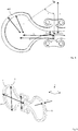
- Figure 1 illustrates one embodiment of a spring element 100 according to the invention.
- the spring element of Figure 1 can be divided into two loop sections 102 and 104, which loop sections connect in the middle of the spring such that the loop sections 102 and 104 together form a full and uniform loop.
- the spring element 100 comprises also a fastening portion, which may include a first fastening element 106 on a first side of the loop, and a second fastening element on the second side of the loop for fastening the spring to the target, whose vibrations are to be controlled.
- the spring element of Figure 1 is preferably symmetric such that the loop sections and fastening portions are mutually symmetric with respect to the middle of the spring element.
- the fastening portions can, however, be implemented as asymmetric in contrast to what is shown in Figure 1 .
- the fastening portions can be of different type on the different sides of the spring, on one side of the spring there may be provided a portion enabling a screw connection, and on the other side of the spring there may be provided a portion enabling a welding connection.
- the loop portions can be divided into smaller portions.
- the loop portion 102 can be divided to an end curve 102A, transition portions 102B on both sides of the end curve, and two inner curves 102B as extensions of the transition portions.
- the end curve refers in Figure 1 the portion residing on the left of the left-side dashed line
- the transition portions refers to the portion between the dashed lines
- the inner curve refers to the portion of the spring which extends from the dashed line on the right to the middle of the fastening element 106 of the fastening portion when seen in the longitudinal direction of the spring, that is in the direction of the x-axis in Figure 5 .
- one fastening portion When applied for the purpose of vibration isolation, one fastening portion is fastened either to the vibrating device/structure or the device/structure which is aimed to be isolated from the vibration.
- the other fastening portion is fastened to the opposite device/structure.
- the spring can act as a vibration isolator in its compression direction when the device/structure fastened to the fastening portion presses the fastening portions towards each other.
- the greatest distance which the fastening portions can move towards each other in a compression situation is on s max ( Figure 4 ).
- the spring can be designed such, for instance, that it can bottom out to avoid permanent transformations of the structure.
- the selection of the measure is affected the mass the spring is bearing, possible external static load, the vibration amplitude, and also the stiffness and strength of the manufacturing material of the spring.
- the spring can also be used in other orientations.
- the spring can be applied as a vibration isolator in the vertical direction also in such a way that the device/structure fastened to the fastening portions pulls the fastening portions away from each other.
- This orientation can be called as tension-direction orientation.
- the greatest allowable operating distance is s max but nothing limits the operating distance if load is increased over the sustainability limit of the spring.
- plastic deformations can always take place in the spring if operating distance is not limited by any other limiting mechanism.
- the performance of the spring is similar as in the compression direction.
- the spring operates also very well when used in transverse orientation such that one of the fastening portions is fastened to the device/structure loading the spring in a transverse direction. Then, by using the spring, values of the natural frequency may be even 30 % smaller than in vertical mounting. In an overloading situation, the spring can have a plastic deformation in a similar way as in tension-direction mounting if this is not limited in anyway.
- the spring can also be used when loaded in its longitudinal orientation, although its performance is worse than when used in vertical orientation. Then, one of the fastening portions is fastened to the device/structure, which loads the spring in longitudinal direction. Then, about 10 % higher natural frequencies can be achieved compared to situation when the spring is mounted vertically. In an overload situation, the spring can have plastic deformation in a similar manner than in tension-direction mounting if this is not limited in some manner.
- Mounting direction is usually determined by the usage and needs thereof, such as use of space or some other need associated with the fastening.
- Static vertical load is a critical and important factor in selection of the spring and in determination of the mounting orientation.
- the flexing is always desired to all three directions, and it is thus an important characteristic that the spring according to embodiments flexes, independent of the mounting direction, to all three directions, and provides thus a low natural frequency in each direction, and thereby good vibration isolation capability to all three directions.
- Figure 2 shows another advantageous embodiment of a spring element 200.
- the difference to the embodiment of Figure 1 is that in the spring element of Figure 2 there is only one loop section 202 acting as vibration isolator. On the opposite side of the loop section the spring element is open ending to freely residing fastening portions 206 and 208, whereby the spring element as a whole does not form a uniform loop.
- the structure shown is especially useful in situations where the structure of Figure 1 having two loop portions is not applicable due to space reasons, for instance.
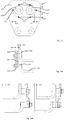
- Figure 3 illustrates preferred dimensions and relations of different portions of the loop sections.
- the end curves such as the end curve 302 have been formed such that it comprises an at least partly converging portion when moving from the middle of the end curve towards the ends of the end curve.
- the profile is convergent on the whole length of the end curve, whereby the widest point of the profile, when observed from a side, can be in the middle of the end curve, which has been depicted with letter e in Figure 3 .
- the smallest width of the profile of the end curve can be at the ends of the end curve depicted with letters f in Figure 2 .
- This convergent form ensures an even stress distribution in a large portion of the end curve. Due to the even stress distribution, stiffness of the spring in relation to the ability to carry load becomes lower, whereby lower natural frequency values for the spring-mass system can be achieved in vibration isolation use. In other words, the performance of the spring improves.
- the width of the profile can change on the distance x 2 depicted by dashed lines such that it decreases substantially parabolically, that is to second power as a function of the distance.
- the shown form is preferred as the spring has sufficient mechanical strength at the end of the end curve but by making the spring thinner can spring properties be significantly improved.
- the width of the profile changes during the distance x 1 illustrated by dashed line such the width decreases substantially quadratically, that is to second power as a function of the distance.
- This form is advantageous in order to achieve sufficient mechanical strength at the end of the fastening portion still ensuring good spring properties at the other end of the inner curve.
- Form of the transition portions can vary from those illustrated in Figure 3 .
- the concave inner side of the area has been rounded to smooth whereby the convex outer side of the spring can have different forms.
- the width of the transition portion is, in the whole transition portion, higher or equal to the measures f and q of the ends of the transition portion.
- Figure 4 illustrates form and measures of one embodiment of the spring element.
- the inner edge of the end curve is formed of a circle segment having a radius r i .
- the end curve can be defined to be formed of a segment that is determined by a line drawn via the center point of said radius when the spring is positioned horizontally, that is the longitudinal direction of the spring is in horizontal plane.
- the new line when intersecting the inner curve points the location where the inner curve ends and where the smallest width q of the inner curve, that is depicted in Figure 3 , resides.
- The, in Figure 3 shown, greatest width p of the inner curve resides just before the point where the outer edge line of the inner curve begins to curve more steeply towards the fastening portion. This more steeply arching portion is always present in the structure apart of the design of the actual fastening portion.
- the fastening portion can thus be considered to be that portion of the spring element which follows after this steepened rounding outside the spring area.
- the outer curve of the end curve of the spring element is formed as a circle segment defined by the radius r o .
- the starting points of the radiuses r o ja r i and thus the center points of circle segments defining the outer curve and inner curve do not reside in the same point, which leads to height variation of the spring profile at the area of the end curve.
- Figure 4 shows one way to implement variation of the profile height at the area of the end curves
- the embodiments are not limited to the shown way but the variation can also be implemented in alternative ways.
- Figure 5 further illustrates dimensioning of the spring element.
- the spring element has been placed into a coordinate system, where the x-axis points to the longitudinal direction of the spring, y-axis to height direction of the spring and z-axis to the transverse direction of the spring.
- the distance from one side to the other side of the spring is thus b.
- the longitudinal dimension (x-axis) of the spring a that is the length of the loop section, is defined as the distance from the outer edge of the end curve to the center of the spring (point O in Figure 3 ), and the dimension is preferably as great as possible to achieve as low stiffness as possible.
- the lower limit 7.5 of the mentioned value range is advantageous because if the ratio would be smaller then manufacturing by cutting from a plate would be difficult. Furthermore, if the ratio would be smaller than 7.5 also the transverse stiffness increases whereby the performance of the spring to that direction for vibration isolation purposes would deteriorate.
- the springs have to preferably be used as coupled to each other as otherwise the spring structure is not stabile but there is a risk for buckling when the spring is loaded.
- the upper value 500 of the value range is advantageous because in such cases the spring can still be applied as presented above comprising one or two loop sections and fastening portions connected to those. If a value higher than 500 is used, the above shown structure is no longer applicable but the springs need to be fastened to each other also from other areas in addition to the fastening portions. This is due to the fact that if other portions of the spring than the fastening portion can slide in height and longitudinal directions with respect to other springs, it can occur that the spring can buckle independent of how many springs are used in the assembly. The root cause for this is that a laminar structure is less stiff when bent compared to a homogenic structure.
- the preferred value range a/b is between 7.5 ... 500, but even more preferably the mentioned ratio is between 10 ... 150 when the transverse stiffness of the spring is always sufficiently low in order to provide high performance also in transverse direction.
- a single spring can be used to form a vibration isolator. Thereby the spring is still with this value possible and easy to manufacture by cutting from a plate.
- the vibration isolator typically formed of several springs and this assembly is not sensitive for losing stability.
- the ratio between the longitudinal measure of the loop portion and the thickness of the spring is between 15 ... 30 when the vibration isolator can be made of one spring without assembly. Then the stiffness of the spring to all directions is low and performance to all directions is good. A single spring is also not sensitive to loss of stability or buckling in the whole value range.
- the distance L 1 between the fastening points or other fastening areas is preferably as small as possible.
- the spring element according to the embodiments is preferably manufactured, as a whole, by only using one material or material alloy.
- the spring element is manufactured from metal materials such as steel, titanium or aluminium.
- the embodiments are not, however, limited to that the spring is manufactured from steel, but the spring element can also be manufactured from elastomer materials, such as polyamide, polyethylene, ABS, polycarbonate, polypropene or reinforced plastic such as fiber glass or carbon fiber.
- the surfaces of the spring can be classified to two different finish classes of the surface, which are formed in manufacture.
- the surface D which refers to the continuous outer surface of the spring including curved portions
- surface E which is the inner surface of the spring containing curved portions
- the surface finish on those surfaces is modest.
- the surface finish can correspond, e.g. to surface finish obtained in thermic cutting or water cutting.
- the surface F which is a straight surface such that a surface normal positioned to any point on the surface always points to the same direction in the limits of the manufacturing tolerance, and also the alike surface G on the opposite side of the spring, have a more precise surface finish requirement.
- the surface finish can correspond to rolling surface of a steel plate obtained by hot rolling or cold rolling. Then it is possible to use surfaces F and G as fastening surfaces for screw attachments.
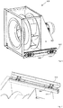
- Figure 6 illustrates one exemplary usage target of the spring element according to the embodiments.
- Figure 6 shows a fan 620 whose vibration behavior is about to be controlled.
- the fan includes a fastening rail 622 by which the fan is fastened to a base structure 640 arranged on a floor or similar.
- the fastening has been done by the vibration isolators 600 according to embodiments.
- the vibration isolators 600 have been fastened from their fastening portions both the fastening rail 622 of the fan, and also the base structure 640 of the floor, whereby the fastening rail stays at a distance from the base structure, which distance is defined by the spring element.
- the springs form vibration isolation between the fan and fastening rails, whereby the fastening rails can be fastened to the floor or other base structure such that the vibration induced by the fan does not significantly transfer to this fastening structure.
- Figure 6 shows the fastening portions as mutually similar, they can in this and other embodiments be implemented differently, such as one being a screw fastening and the other one as a welding connection.
- Figure 6 shows the upper structure 622, lower structure 640 and spring forming a fully integrated structure
- the spring could alternatively be form as a part of one of the structures 622 or 640. In the situation of Figure 6 , for instance, this would mean that the spring could be cut into the upper structure 622 when it is being cut without the lower structure 640.
- the lower structure could be manufactured as a separate structure such that there are provided spaces for the lower halves of the loop sections of the spring and also holes or other fastening means for fastening of the spring.
- Figure 7 shows an embodiment where the vibration isolation has been arranged to happen in the transverse, that is, z-direction as shown in Figure 5 . Then the fastening rail 722 belonging to the structure and a separate base structure 740 reside in different planes in transverse direction of the spring but it is clear that the embodiments are not restricted thereto but the fastening can as well be done to objects residing in the same plane.
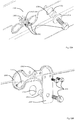
- Figure 8 shows one embodiment of use of the spring element according to the embodiments such that the vibration isolator is formed of two or more springs by connecting the springs side-to-side such that springs (one pair or several pairs) are separated by using intermediate plates or other structures.
- a kind of laminar structure is formed.
- One example of such structure is illustrated in Figure 8 where the spring elements 800A and 800B have been separated from each other with the intermediate plate 850.
- the intermediate plate is preferably of the same material as the spring such as steel but can also be of a different material.
- the intermediate plate is arranged only to the area of the fastening portion.
- a vibration isolator flexing to all directions can be formed by using two springs, for instance, such that the springs are set perpendicular to each other whereby the longitudinal direction of one spring coincides with the transverse direction of the other spring.
- the springs can be arranged such that the fastening area/transition portion/inner curve sets inside of the spring loop of the perpendicularly residing, and for instance the adjacent pair of springs 900A, 900B is arranged in this way with respect to the pair of springs 900C, 900D.
- Figure 10 shows an embodiment where the spring 1000 is fully integrated to the frame or base structure 1022 of the device in the same manufacturing process when the frame or base structure is manufactured.
- This is an advantageous embodiment as often the devices nowadays are manufactured from plates and integration can be a very relevant option in many devices. Thereby, by cutting the spring form directly to the product during its manufacturing, acquiring of separate springs and fastening of them to the structures can be completely avoided.
- the embodiments allow manufacturing of also a variation where only one fastening portion is integrated to be part of the device structure and the other fastening portion is designed for considering some other way of fastening, such as fastening by means of screw fastening or by welding.
- Figures 11A to 11C illustrate some embodiments of the fastening portions.
- Figure 11A corresponds, from its fastening portion 1106 the structure shown in Figure 1 where the fastening portion includes one or more through holes passing through the spring for screw connection, for instance.
- Figure 11B shows a fastening member 1106B which is welded to the structure.
- Figure 11C illustrates a structure where the spring has been integrated to the surrounding structure, that is formed to be a part of a plate, for instance, as shown in Figure 10 .
- the fastening portion 1106C shows one possible design for such fastening portion.
- the form of the fastening portion can vary depending on the application and the way of fastening, and the invention is not limited to how the fastening portions are implemented.
- a limiting arrangement arranged in connection of or in proximity of the spring element for limiting the flexing and compression and bending of the spring element in all three mutually perpendicular degrees of freedom beyond respective predetermined limits.
- a limiting arrangement is preferable for use in applications which may be subject to an earthquake, for instance. An earthquake might induce such a great vibration impact to the structure that the spring could damage.
- the limiting arrangements are configured to limit the load to the springs to such a level that the tension does not exceed the yield limit of the spring and the properties of the spring can sustain the earthquake.
- the limiting arrangement is configured to mechanically prevent the mutual movement of the fastening portions of the spring element in all three coordinate directions.
- the limiting arrangement may be advantageous and applicable in vehicles, where a collision or an accident situation could cause overloading or ripping of the spring element or the respective fastenings.
- the limiting arrangement can be dimensioned to sustain loads that are, for instance, 10-fold to the loads normally allowed by the spring element.
- Figures 12A and 12B show an embodiment of a limiting arrangement.
- a first base structure 1222 attached to a vibrating structure and a base structure 1240 attached to a rigid structure.
- the spring element 1200 is arranged between the structures such the base structures do not touch each other, and the spring element defines the distance between them.
- the actual limiting arrangement is formed by the limiting plate 1201, the limiting sleeves 1202 and the adjustment plates 1203.
- the spring element 1200 has fastening portions with apertures to which fastening members 1204, such as bolts or screws have been inserted. Between the spring element 1200 and the structures whose mutual movement is to be attenuated is arranged a first limiting plate 1201 for limiting the flexing/compression of the spring in longitudinal and height direction.
- the limiting plate 1201 is attached to the fixed based structure 1240 and is thus basically stationary.
- the plate 1201 has also a larger opening for receiving the sleeves 1202 that receive the fastening members 1204 for fastening to the moving/vibrating base structure 1222. As shown in the drawings, there is a certain clearance between the sleeves and the edges of the larger opening whereby the sleeves 1202 can move in the opening in vertical height direction and in horizontal length direction of the spring. If the movement of the structures with respect to each other exceeds a predetermined greatest allowable distance, one of the sleeves 1202 hits the edge of the opening in the limiting plate 1201 thereby preventing the damage of the spring element.
- Figures 12A and 12B show two fastening members on upper and lower sides of the spring, there may be other number of such fastening members ranging from one to three, for instance. Furthermore, even though Figures 12A and 12B show base plates 1222, 1240, use of those is not obligatory, but the fastening members 1240 could alternatively attach directly to the respective structures.
- Figure 13 highlights dimensioning between the openings and the sleeves 1302 in the limiting plate 1301.
- a predetermined distance ⁇ x1 when the movable structure moves to the left there is set a predetermined distance ⁇ x2 when the movable structure moves to the right.
- the respective distances are ⁇ y1 upwards and ⁇ y2 downwards.
- the predetermined dimensions are implemented by the form of the aperture and also by design of the sleeves 1302. Above has been discussed only the movement along the coordinate directions (x- and y-axis) but if there is movement to both these directions at the same time, this is similarly taken into account in form of the opening in the limiting plate and/or in the form of the sleeves 1302.
- the outer edge of the sleeve 1302 can alternatively be square, rectangular, triangle or polygon. If the form of sleeve differs from circular, this needs to be taken into account in defining the clearances between the sleeve and the opening. Furthermore, the number of sleeves is not limited to two but there can be e.g. 1, 3 or 4 of them.
- transverse direction z-direction
- the movement/displacement/bending limitation is done differently than in longitudinal and height direction, which is illustrated by reference to Figures 14A and 14B .
- the movable structure 1422 moves transversely along the z-axis, also the upper fastening portion of the spring element moves accordingly.
- the limiting plate 1401 can accordingly move between the structures 1400 and 1422.
- the movable structure 1422 move only distance ⁇ z 2 to the left before the movable structure 1422 collides the limiting plate 1401. And the movable structure 1422 can move only distance ⁇ z 1 to the right before the vibration element 1400 collides the limiting plate 1401.
- Adjustment of the magnitude of the transverse displacement can be effected by appropriate selection of the thicknesses ⁇ z 1 and ⁇ z 2 of the adjustment plates 1403.
- the two thicknesses can be independent of each other and thus also different from each other. Practically it needs to be ensured that the colliding surfaces in the vibration element, moving structure and the limiting plate are great enough to sustain the stress of the collision.
- the sleeves can be made of elastic material or can at least have an elastic surface treatment.
- the sleeve comprises an additional collision surface at the end of the sleeve having a greater cross-section than that of the sleeve to provide sufficient collision area.
- Figure 15A shows another embodiment of a limiting arrangement.
- the spring element 1500 is formed integrally as part of one structure (movable or rigid) and the limiter is arranged separately from the spring element.
- the spring element is manufactured as an integral part of the first structure 1540. Thereby the fastening or connecting portion of the spring can be considered to constitute the area of the spring that is in contact with the first structure.
- the second fastening portion of the spring is fastened to the movable structure 1522 by means of screws/bolts 1504.
- the limiting functionality is provided by means of an aperture 1501 in the structure 1540 and the sleeve 1502.
- the sleeve 1502 has smaller diameter than the hole 1501 whereby the hole sets limits for the sleeve to move therein.
- the displacement is limited on the other hand by the structures colliding to each other, and on the other hand the first structure 1540 colliding to a separate counter plate 1506.
- Figure 15B shows a spring element 1500 which is fully integrated to the plate structure, and in connection to which is arranged a movement/displacement/flexing limiter configured to perform limitation to all directions.
- the x- and y-directions limiter mechanism provided by components 1501 and 1502 is similar as in Figure 15A .
- the limiter is arranged below the spring in height direction.
- an adjustment plate 1503 that sets the maximal displacement between the structures.
- a counter plate that prevents the structures to displace from each other more than the thickness of plate 1503.
- similar mechanism is arranged on the other side of the spring, that is there are provided also components 1503 and 1507 to prevent transverse movement to the opposite direction.
- a limiter arrangement for protecting a spring element arranged to attenuate vibrations between two structures that move and/or vibrate with respect to each other.
- the limiter arrangement is configured to limit the movement of the two structures below predetermined safety limits so that the spring element is not flexed/compressed/twisted beyond sustainable limits.
- the limiter arrangement is configured to operate in all three coordinate directions.
- the x-and y-axis displacement limitation is based on the limiter arrangement having a fixed first connection to one of the structures and a movable connection to the second structure.
- the movable connection comprises an aperture wherein a sleeve is allowed to move such that the edges of the aperture define the space wherein the sleeve can move.
- the limiting arrangement is operatively connected to the spring.
- the spring element and limiting arrangement even use same bolts or screws for fastening to the structures.
- the limiting mechanism is aside of the spring, that is, it can be on the side of the spring, or below or top of it.
- one of the fastening portions is movable with respect to the other fastening portion of the spring.
- One of the fastening portions is fixed, and the other one can move in transverse direction on both sides of the fixed fastening portion.
- the limiting arrangement is applicable in situations where the spring element is a standalone product attachable to the structures. It is also applicable in half-integrated solutions when one fastening/connecting portions is integrated to one of the structures and one is separately fastened by means of bolts/screws. The embodiments are also applicable in fully integrated solutions where the vibrating structures share a plate and the spring is manufactured therein.
- a spring structure which comprises a spring element as depicted herein, which spring structure comprises a limiting arrangement for limiting the flexing and compressing and bending of the spring element beyond predetermined limits when connected to a first structure and a second structure.
- Flexing and compressing refer here to operation of the spring element in x- and y-directions and bending happens in transverse direction.
- the limiting arrangement comprises a rigid fastening to one of the structures whose movement with respect to each other is to be attenuated, the limiting arrangement further comprising a sleeve-aperture arrangement, wherein the diameter of the sleeve is smaller than the aperture, the sleeve is allowed to move within the aperture such that the collision points between the sleeve and aperture define the limits for the structure movements and thereby limits for spring element flexing or compressing.
- the sleeve-aperture arrangement can be provided in a separate limiting plate, which can be of uniform thickness. The limiting plate can be mounted parallel to the mounting direction of the spring element.
- the spring element is half- or fully integrated to the structure when the sleeve-aperture arrangement is also arranged to the structure.
- a spring structure wherein the limiting arrangement comprises a limiting plate, which limiting plate comprises one or more first apertures for receiving a first fastening member for fastening a spring element rigidly to a first structure, the limiting plate further comprising one or more second apertures for receiving a second fastening member for fastening the spring element to a second structure, there being provided a sleeve around the fastening member, the sleeve having a smaller cross-section than the second aperture.
- a spring structure wherein the limiting arrangement comprises, for limiting transverse bending of the spring element, a fixed fastening to at least one of the structures, and two limiting surfaces for limiting the movement of the structures in transverse direction.
- the limiting surfaces can be the structure and/or the spring element of Figure 14A between which the limiting plate can move.
- the limiting surfaces can also be the plates 1506, 1507 of Figure 15B .
- a spring structure wherein the limiting characteristics of the limiting arrangement are selectable by selecting one or more of the following: form of a sleeve 1202, diameter of a sleeve 1202, diameter of aperture 1501 defining movement limits of the sleeve, design of aperture 1501 defining movement limits of the sleeve, thickness of plate 1203, 1403, 1503 applied between a spring element and a limiting plate 1201 or between a limiting plate 1201 and a structure 1240 or between a spring element 1500 and a structure 1522 or between a structure and a counter plate 1507.
- the adjustment of the limiting characteristics can be selected e.g. based on the characteristics of the spring or based on the usage environment.
Landscapes
- Engineering & Computer Science (AREA)
- General Engineering & Computer Science (AREA)
- Mechanical Engineering (AREA)
- Physics & Mathematics (AREA)
- Acoustics & Sound (AREA)
- Aviation & Aerospace Engineering (AREA)
- Springs (AREA)
Abstract
Description
- The invention relates to the structure of a spring element applied in vibration management.
- Vibration management is a widely known area of mechanics. The goal in vibration management typically is the reduction of vibration of structures by means of different passive and active ways. Passive ways include, for instance, without an external energy source or control operating springs, which isolate a vibrating structure from another structure such that an undesirable vibration does not transfer between the structures. Passively operating dampers absorb energy of the vibration and thereby reduce the amplitude of the vibration. It is also possible to include a so-called passive mass damper which is a combination of a spring and a mass. The natural frequency of this combination is set to a frequency that corresponds to the problematic natural frequency of the structure, and thereby cancels vibration occurring on the natural frequency.
- By means of using vibration management components it is also targeted to reduce or prevent vibration or stress influence to structures caused by different impact-like stresses. By means of vibration management, optimally, it is accomplished a structure that vibrates itself very little, causes very little vibration and noise to the surrounding domains and is very durable. Thereby the environmental impact in terms of vibration and noise are minimal, and the structure and its surrounding structures are not damaged, in the best case, at any time during its life-time.
- Plurality of solutions have been developed to perform vibration management in the above-mentioned areas. There is, however, still need for a spring that is simple and economic to manufacture, and has very high performance as a vibration isolator in all directions of the vibration.
- It is the objective of the invention to at least partly alleviate the above-mentioned problem. This is achieved with the invention that is the scope of the independent claim. Preferred embodiments have been disclosed in the dependent claims.
- The spring element according to the invention provides the advantage that it is simple and economic to manufacture and has very high performance as a vibration isolator to all vibration directions.
- The invention and its preferred embodiments are shown in the accompanying drawings, where
-
Figure 1 shows a side view of a spring element according to an embodiment of the invention -
Figure 2 shows a spring element according to another embodiment of the invention; -
Figure 3 illustrates dimensioning associated with the spring element; -
Figure 4 also illustrates dimensioning associated with the spring element; -
Figure 5 further illustrates dimensioning associated with the spring element according to the embodiments; -
Figure 6 illustrates one embodiment of the use of the spring element as a vibration isolator; -
Figure 7 illustrates another embodiment of the use of the spring element as a vibration isolator; -
Figure 8 illustrates use of two spring elements together to form a vibration isolator; -
Figure 9 illustrates use of several spring elements together in order to form a vibration isolator; -
Figure 10 illustrates integration of a spring element as a part of a plate structure; -
Figure 11 shows some embodiments for implementation of the fastening portion; -
Figure 12A shows one embodiment of a limiter arrangement; -
Figure 12B shows another view of the limiter arrangement ofFigure 12A ; -
Figure 13 highlights dimensioning in the limiter arrangement; -
Figure 14A shows a side view of a limiter arrangement; -
Figure 14B shows the limiter arrangement ofFigure 14A in two different usage positions; -
Figure 15A shows a partly integrated limiter arrangement; and -
Figure 15B shows a fully integrated limiter arrangement. - The embodiments relate to a new spring/spring element manufactured by cutting from a plate, by cutting/perforating/forming to a plate or by casting, for instance, which spring element can be utilized in vibration isolation purposes, that is, to prevent vibration to transfer from one structure to another. The spring element according to the embodiments has a thin structure, flexes to all directions, and has a low profile. By using the spring element, it is possible to form a passive vibration isolation arrangement by placing one or more spring elements as a load carrying structure between two masses.
- Possible uses of the spring element are all structures and vibrating machines in machine building industry, construction industry, vehicle industry or in any other use where it is desired to control the mechanical vibration, or it is desired to use the spring in other present or future usage applications of springs. Examples of the usage areas include process equipment, vehicles, sensitive electric devices, motors and measurement devices.
-
Figure 1 illustrates one embodiment of aspring element 100 according to the invention. On a coarse level, the spring element ofFigure 1 can be divided into twoloop sections loop sections spring element 100 comprises also a fastening portion, which may include afirst fastening element 106 on a first side of the loop, and a second fastening element on the second side of the loop for fastening the spring to the target, whose vibrations are to be controlled. The spring element ofFigure 1 is preferably symmetric such that the loop sections and fastening portions are mutually symmetric with respect to the middle of the spring element. The fastening portions can, however, be implemented as asymmetric in contrast to what is shown inFigure 1 . The fastening portions can be of different type on the different sides of the spring, on one side of the spring there may be provided a portion enabling a screw connection, and on the other side of the spring there may be provided a portion enabling a welding connection. - Further specified, the loop portions can be divided into smaller portions. For example, the
loop portion 102 can be divided to anend curve 102A,transition portions 102B on both sides of the end curve, and twoinner curves 102B as extensions of the transition portions. The end curve refers inFigure 1 the portion residing on the left of the left-side dashed line, the transition portions refers to the portion between the dashed lines, and the inner curve refers to the portion of the spring which extends from the dashed line on the right to the middle of thefastening element 106 of the fastening portion when seen in the longitudinal direction of the spring, that is in the direction of the x-axis inFigure 5 . - When applied for the purpose of vibration isolation, one fastening portion is fastened either to the vibrating device/structure or the device/structure which is aimed to be isolated from the vibration. The other fastening portion is fastened to the opposite device/structure. The spring can act as a vibration isolator in its compression direction when the device/structure fastened to the fastening portion presses the fastening portions towards each other. The greatest distance which the fastening portions can move towards each other in a compression situation is on smax (
Figure 4 ). Thereby the spring can be designed such, for instance, that it can bottom out to avoid permanent transformations of the structure. The selection of the measure is affected the mass the spring is bearing, possible external static load, the vibration amplitude, and also the stiffness and strength of the manufacturing material of the spring. - The spring can also be used in other orientations. The spring can be applied as a vibration isolator in the vertical direction also in such a way that the device/structure fastened to the fastening portions pulls the fastening portions away from each other. This orientation can be called as tension-direction orientation. Also in such a case the greatest allowable operating distance is smax but nothing limits the operating distance if load is increased over the sustainability limit of the spring. Thus, in such an orientation, plastic deformations can always take place in the spring if operating distance is not limited by any other limiting mechanism. However, the performance of the spring is similar as in the compression direction.
- The spring operates also very well when used in transverse orientation such that one of the fastening portions is fastened to the device/structure loading the spring in a transverse direction. Then, by using the spring, values of the natural frequency may be even 30 % smaller than in vertical mounting. In an overloading situation, the spring can have a plastic deformation in a similar way as in tension-direction mounting if this is not limited in anyway.
- The spring can also be used when loaded in its longitudinal orientation, although its performance is worse than when used in vertical orientation. Then, one of the fastening portions is fastened to the device/structure, which loads the spring in longitudinal direction. Then, about 10 % higher natural frequencies can be achieved compared to situation when the spring is mounted vertically. In an overload situation, the spring can have plastic deformation in a similar manner than in tension-direction mounting if this is not limited in some manner.
- Mounting direction is usually determined by the usage and needs thereof, such as use of space or some other need associated with the fastening. Static vertical load is a critical and important factor in selection of the spring and in determination of the mounting orientation. Typically, in vibration isolation, the flexing is always desired to all three directions, and it is thus an important characteristic that the spring according to embodiments flexes, independent of the mounting direction, to all three directions, and provides thus a low natural frequency in each direction, and thereby good vibration isolation capability to all three directions.
-
Figure 2 shows another advantageous embodiment of aspring element 200. The difference to the embodiment ofFigure 1 is that in the spring element ofFigure 2 there is only oneloop section 202 acting as vibration isolator. On the opposite side of the loop section the spring element is open ending to freely residingfastening portions Figure 1 having two loop portions is not applicable due to space reasons, for instance. - Following figures illustrate dimensions associated with the spring element and it is obvious that the dimensioning principles are applicable to spring elements having one or two loop sections.
-
Figure 3 illustrates preferred dimensions and relations of different portions of the loop sections. Preferably the end curves, such as theend curve 302 have been formed such that it comprises an at least partly converging portion when moving from the middle of the end curve towards the ends of the end curve. In one embodiment, the profile is convergent on the whole length of the end curve, whereby the widest point of the profile, when observed from a side, can be in the middle of the end curve, which has been depicted with letter e inFigure 3 . Correspondingly, the smallest width of the profile of the end curve can be at the ends of the end curve depicted with letters f inFigure 2 . This convergent form ensures an even stress distribution in a large portion of the end curve. Due to the even stress distribution, stiffness of the spring in relation to the ability to carry load becomes lower, whereby lower natural frequency values for the spring-mass system can be achieved in vibration isolation use. In other words, the performance of the spring improves. - Preferably the largest profile width e and the smallest profile width f are related to each other such that e/f = 1.6 ... 4. The width of the profile can change on the distance x2 depicted by dashed lines such that it decreases substantially parabolically, that is to second power as a function of the distance. The shown form is preferred as the spring has sufficient mechanical strength at the end of the end curve but by making the spring thinner can spring properties be significantly improved. Even more preferably, the mentioned ratio is between e/f = 1.6 ... 3 or even more preferably e/f = 1.6 ... 1.8 when the length of the spring decreases. The ratio e/f = 1.6 ... 1.8 can become to question, for instance, in a situation when the length of the spring has at least substantially dimensions as shown in
Figure 1 and can be positioned to a longitudinally compact space. - The greatest width p and the smallest width q of the inner curves of the spring are related to each other such that p/q = 2 ... 5. The width of the profile changes during the distance x1 illustrated by dashed line such the width decreases substantially quadratically, that is to second power as a function of the distance. This form is advantageous in order to achieve sufficient mechanical strength at the end of the fastening portion still ensuring good spring properties at the other end of the inner curve. Even more preferably the mentioned ratio is between p/q = 2 ... 2.5 the spring height being lower. The ratio p/q = 2 ... 2.5 may be applicable in an embodiment corresponding to dimensions shown in
Figure 1 , whereby the spring can be placed into a compact space in height direction. - Form of the transition portions can vary from those illustrated in
Figure 3 . Preferably the concave inner side of the area has been rounded to smooth whereby the convex outer side of the spring can have different forms. Preferably, however, the width of the transition portion is, in the whole transition portion, higher or equal to the measures f and q of the ends of the transition portion. -
Figure 4 illustrates form and measures of one embodiment of the spring element. As can be seen, the inner edge of the end curve is formed of a circle segment having a radius ri. The end curve can be defined to be formed of a segment that is determined by a line drawn via the center point of said radius when the spring is positioned horizontally, that is the longitudinal direction of the spring is in horizontal plane. - When the spring element is positioned as mentioned above, the inner curve can be defined by first drawing a vertical dashed line travelling via the center of the fastening portion. To this line two points are placed. The first point O is placed to the level of the mass center of the end curve of the spring. The second point B is placed above point O to a distance xi, which is the same distance as the distance of the center point of the inner edge of the curve from point O. Then a new dashed line is drawn via point B such that an angle is formed between the segment OB and the new line, which angle is substantially α = 55° as shown in
Figure 4 . The new line, when intersecting the inner curve points the location where the inner curve ends and where the smallest width q of the inner curve, that is depicted inFigure 3 , resides. The, inFigure 3 shown, greatest width p of the inner curve resides just before the point where the outer edge line of the inner curve begins to curve more steeply towards the fastening portion. This more steeply arching portion is always present in the structure apart of the design of the actual fastening portion. The fastening portion can thus be considered to be that portion of the spring element which follows after this steepened rounding outside the spring area. - Correspondingly, the outer curve of the end curve of the spring element is formed as a circle segment defined by the radius ro. As can be seen, the starting points of the radiuses ro ja ri, and thus the center points of circle segments defining the outer curve and inner curve do not reside in the same point, which leads to height variation of the spring profile at the area of the end curve.
- Even though
Figure 4 shows one way to implement variation of the profile height at the area of the end curves, the embodiments are not limited to the shown way but the variation can also be implemented in alternative ways. - Above has been disclosed the variation of the profile height at the area of the end curve but also the inner curves can include similar areas where the profile height varies similarly as in the case of the end curves.
-
Figure 5 further illustrates dimensioning of the spring element. The spring element has been placed into a coordinate system, where the x-axis points to the longitudinal direction of the spring, y-axis to height direction of the spring and z-axis to the transverse direction of the spring. - In the transverse direction the distance from one side to the other side of the spring is thus b. Preferably the spring is manufactured by cutting from a plate whereby the transverse dimension b is determined by the thickness of the plate. In this direction the dimension is thus limited by the cutting process, whereby the dimension can practically vary between b = 0.5 mm ... 200 mm.
- The longitudinal dimension (x-axis) of the spring a, that is the length of the loop section, is defined as the distance from the outer edge of the end curve to the center of the spring (point O in
Figure 3 ), and the dimension is preferably as great as possible to achieve as low stiffness as possible. In preferred embodiments of the invention the ratio between a and b is between a/b = 7.5 ... 500. - The lower limit 7.5 of the mentioned value range is advantageous because if the ratio would be smaller then manufacturing by cutting from a plate would be difficult. Furthermore, if the ratio would be smaller than 7.5 also the transverse stiffness increases whereby the performance of the spring to that direction for vibration isolation purposes would deteriorate.
- If the applied ratio value a/b is too big, the springs have to preferably be used as coupled to each other as otherwise the spring structure is not stabile but there is a risk for buckling when the spring is loaded. The upper value 500 of the value range is advantageous because in such cases the spring can still be applied as presented above comprising one or two loop sections and fastening portions connected to those. If a value higher than 500 is used, the above shown structure is no longer applicable but the springs need to be fastened to each other also from other areas in addition to the fastening portions. This is due to the fact that if other portions of the spring than the fastening portion can slide in height and longitudinal directions with respect to other springs, it can occur that the spring can buckle independent of how many springs are used in the assembly. The root cause for this is that a laminar structure is less stiff when bent compared to a homogenic structure.
- Above has been disclosed that the preferred value range a/b is between 7.5 ... 500, but even more preferably the mentioned ratio is between 10 ... 150 when the transverse stiffness of the spring is always sufficiently low in order to provide high performance also in transverse direction. When the value is closer to value 10, a single spring can be used to form a vibration isolator. Thereby the spring is still with this value possible and easy to manufacture by cutting from a plate. On the other hand, when the value is close to 150, is the vibration isolator typically formed of several springs and this assembly is not sensitive for losing stability.
- Even more preferably, and most preferably, the ratio between the longitudinal measure of the loop portion and the thickness of the spring is between 15 ... 30 when the vibration isolator can be made of one spring without assembly. Then the stiffness of the spring to all directions is low and performance to all directions is good. A single spring is also not sensitive to loss of stability or buckling in the whole value range.
- The measure c to height direction (y-axis), that is the distance between the end points of the end curves on the outer edge of the spring is preferably such that the ratio a/c = 1.25 ... 4.
- The distance L1 between the fastening points or other fastening areas is preferably as small as possible. The ratio between that measure to the measure b is L1/b = 6 ... 100.
- The spring element according to the embodiments is preferably manufactured, as a whole, by only using one material or material alloy. Preferably the spring element is manufactured from metal materials such as steel, titanium or aluminium. The embodiments are not, however, limited to that the spring is manufactured from steel, but the spring element can also be manufactured from elastomer materials, such as polyamide, polyethylene, ABS, polycarbonate, polypropene or reinforced plastic such as fiber glass or carbon fiber.
- When the material behaves in its elastic performance area linearly, the optimal predictability for performance is achieved. Thereby also the force - displacement relation of the spring stays linear within the whole application area, which makes it easier to predict the behavior and dimensioning of the vibration isolation system. When the properties of the material stay substantially constant in the whole temperature range of use, this allows to achieve the best predictability.
- The surfaces of the spring can be classified to two different finish classes of the surface, which are formed in manufacture. Referring to
Figure 5 , the surface D, which refers to the continuous outer surface of the spring including curved portions, and surface E, which is the inner surface of the spring containing curved portions, the surface finish on those surfaces is modest. The surface finish can correspond, e.g. to surface finish obtained in thermic cutting or water cutting. The surface F, which is a straight surface such that a surface normal positioned to any point on the surface always points to the same direction in the limits of the manufacturing tolerance, and also the alike surface G on the opposite side of the spring, have a more precise surface finish requirement. The surface finish can correspond to rolling surface of a steel plate obtained by hot rolling or cold rolling. Then it is possible to use surfaces F and G as fastening surfaces for screw attachments. -
Figure 6 illustrates one exemplary usage target of the spring element according to the embodiments.Figure 6 shows afan 620 whose vibration behavior is about to be controlled. The fan includes afastening rail 622 by which the fan is fastened to abase structure 640 arranged on a floor or similar. Instead of the fan being directly fastened to the base structure, the fastening has been done by thevibration isolators 600 according to embodiments. Thevibration isolators 600 have been fastened from their fastening portions both thefastening rail 622 of the fan, and also thebase structure 640 of the floor, whereby the fastening rail stays at a distance from the base structure, which distance is defined by the spring element. By the shown assembly the springs form vibration isolation between the fan and fastening rails, whereby the fastening rails can be fastened to the floor or other base structure such that the vibration induced by the fan does not significantly transfer to this fastening structure. - Even though
Figure 6 shows the fastening portions as mutually similar, they can in this and other embodiments be implemented differently, such as one being a screw fastening and the other one as a welding connection. - Furthermore, even though
Figure 6 shows theupper structure 622,lower structure 640 and spring forming a fully integrated structure, the spring could alternatively be form as a part of one of thestructures Figure 6 , for instance, this would mean that the spring could be cut into theupper structure 622 when it is being cut without thelower structure 640. The lower structure could be manufactured as a separate structure such that there are provided spaces for the lower halves of the loop sections of the spring and also holes or other fastening means for fastening of the spring. -
Figure 7 shows an embodiment where the vibration isolation has been arranged to happen in the transverse, that is, z-direction as shown inFigure 5 . Then thefastening rail 722 belonging to the structure and aseparate base structure 740 reside in different planes in transverse direction of the spring but it is clear that the embodiments are not restricted thereto but the fastening can as well be done to objects residing in the same plane. -
Figure 8 shows one embodiment of use of the spring element according to the embodiments such that the vibration isolator is formed of two or more springs by connecting the springs side-to-side such that springs (one pair or several pairs) are separated by using intermediate plates or other structures. In this way a kind of laminar structure is formed. One example of such structure is illustrated inFigure 8 where thespring elements - By combining several springs, it is possible to assemble a bigger vibration isolator that flexes to all directions. In such an assembly there can be two or more springs, such as in
Figure 9 the vibration isolation assembly has been formed by using eight springs. - A vibration isolator flexing to all directions can be formed by using two springs, for instance, such that the springs are set perpendicular to each other whereby the longitudinal direction of one spring coincides with the transverse direction of the other spring. As
Figure 9 shows, the springs can be arranged such that the fastening area/transition portion/inner curve sets inside of the spring loop of the perpendicularly residing, and for instance the adjacent pair ofsprings springs -
Figure 10 shows an embodiment where thespring 1000 is fully integrated to the frame orbase structure 1022 of the device in the same manufacturing process when the frame or base structure is manufactured. This is an advantageous embodiment as often the devices nowadays are manufactured from plates and integration can be a very relevant option in many devices. Thereby, by cutting the spring form directly to the product during its manufacturing, acquiring of separate springs and fastening of them to the structures can be completely avoided. The embodiments allow manufacturing of also a variation where only one fastening portion is integrated to be part of the device structure and the other fastening portion is designed for considering some other way of fastening, such as fastening by means of screw fastening or by welding. -
Figures 11A to 11C illustrate some embodiments of the fastening portions.Figure 11A corresponds, from its fastening portion 1106 the structure shown inFigure 1 where the fastening portion includes one or more through holes passing through the spring for screw connection, for instance.Figure 11B shows afastening member 1106B which is welded to the structure.Figure 11C illustrates a structure where the spring has been integrated to the surrounding structure, that is formed to be a part of a plate, for instance, as shown inFigure 10 . Thefastening portion 1106C shows one possible design for such fastening portion. - The form of the fastening portion can vary depending on the application and the way of fastening, and the invention is not limited to how the fastening portions are implemented.
- In some embodiments, there may be provided a limiting arrangement arranged in connection of or in proximity of the spring element for limiting the flexing and compression and bending of the spring element in all three mutually perpendicular degrees of freedom beyond respective predetermined limits. Such a limiting arrangement is preferable for use in applications which may be subject to an earthquake, for instance. An earthquake might induce such a great vibration impact to the structure that the spring could damage. The limiting arrangements are configured to limit the load to the springs to such a level that the tension does not exceed the yield limit of the spring and the properties of the spring can sustain the earthquake. The limiting arrangement is configured to mechanically prevent the mutual movement of the fastening portions of the spring element in all three coordinate directions.
- In addition to earthquake situations, the limiting arrangement may be advantageous and applicable in vehicles, where a collision or an accident situation could cause overloading or ripping of the spring element or the respective fastenings.
- The limiting arrangement can be dimensioned to sustain loads that are, for instance, 10-fold to the loads normally allowed by the spring element.
-
Figures 12A and 12B show an embodiment of a limiting arrangement. There are shown afirst base structure 1222 attached to a vibrating structure and abase structure 1240 attached to a rigid structure. Thespring element 1200 is arranged between the structures such the base structures do not touch each other, and the spring element defines the distance between them. The actual limiting arrangement is formed by the limitingplate 1201, the limitingsleeves 1202 and theadjustment plates 1203. - The
spring element 1200 has fastening portions with apertures to whichfastening members 1204, such as bolts or screws have been inserted. Between thespring element 1200 and the structures whose mutual movement is to be attenuated is arranged a first limitingplate 1201 for limiting the flexing/compression of the spring in longitudinal and height direction. The limitingplate 1201 is attached to the fixed basedstructure 1240 and is thus basically stationary. - The
plate 1201 has also a larger opening for receiving thesleeves 1202 that receive thefastening members 1204 for fastening to the moving/vibratingbase structure 1222. As shown in the drawings, there is a certain clearance between the sleeves and the edges of the larger opening whereby thesleeves 1202 can move in the opening in vertical height direction and in horizontal length direction of the spring. If the movement of the structures with respect to each other exceeds a predetermined greatest allowable distance, one of thesleeves 1202 hits the edge of the opening in the limitingplate 1201 thereby preventing the damage of the spring element. - Even though
Figures 12A and 12B show two fastening members on upper and lower sides of the spring, there may be other number of such fastening members ranging from one to three, for instance. Furthermore, even thoughFigures 12A and 12B show base plates fastening members 1240 could alternatively attach directly to the respective structures. -
Figure 13 highlights dimensioning between the openings and thesleeves 1302 in the limitingplate 1301. With regard to longitudinal movement, there is set a predetermined distance Δx1 when the movable structure moves to the left, and a predetermined distance Δx2 when the movable structure moves to the right. In height direction, the respective distances are Δy1 upwards and Δy2 downwards. These dimensions can be selected independently from each other so that e.g. the allowable dimensions in height direction can differ from each other. - Preferably the dimensions are in ranges Δx1 = 0.35b ... 2b and Δx2 = 0.35b ... 2b and Δy1 = 0.6b ... 3.4b and Δy2 = 0.6b ... 3.4b. The predetermined dimensions are implemented by the form of the aperture and also by design of the
sleeves 1302. Above has been discussed only the movement along the coordinate directions (x- and y-axis) but if there is movement to both these directions at the same time, this is similarly taken into account in form of the opening in the limiting plate and/or in the form of thesleeves 1302. - Even though the sleeves have shown to have a circular cross-section, the outer edge of the
sleeve 1302 can alternatively be square, rectangular, triangle or polygon. If the form of sleeve differs from circular, this needs to be taken into account in defining the clearances between the sleeve and the opening. Furthermore, the number of sleeves is not limited to two but there can be e.g. 1, 3 or 4 of them. - In transverse direction (z-direction), the movement/displacement/bending limitation is done differently than in longitudinal and height direction, which is illustrated by reference to
Figures 14A and 14B . When themovable structure 1422 moves transversely along the z-axis, also the upper fastening portion of the spring element moves accordingly. The limitingplate 1401 can accordingly move between thestructures - At the lower end of the limiting structure, however, there is an
adjustment plate 1403 between the limitingplate 1401 and the rigid structure 1440 and also similarly between theplate 1401 and thespring 1400. The adjustment plates prevent moving of the lower end of the spring element in transverse direction with respect to the rigid structure. - Thereby can the
movable structure 1422 move only distance Δz2 to the left before themovable structure 1422 collides the limitingplate 1401. And themovable structure 1422 can move only distance Δz1 to the right before thevibration element 1400 collides the limitingplate 1401. - Adjustment of the magnitude of the transverse displacement can be effected by appropriate selection of the thicknesses Δz1 and Δz2 of the
adjustment plates 1403. Preferably the thicknesses are such that Δz1 = 0.75b ... 4.4b and Δz2 = 0.75b ... 4.4b. The two thicknesses can be independent of each other and thus also different from each other. Practically it needs to be ensured that the colliding surfaces in the vibration element, moving structure and the limiting plate are great enough to sustain the stress of the collision. - If it is aimed that different components of the limiting arrangement would collide gently with each other, e.g. to avoid damages to surfaces, in one embodiment to provide rubber or similar elastic material around the larger hole of the limiting plate. Furthermore, in an embodiment, the sleeves can be made of elastic material or can at least have an elastic surface treatment. In one embodiment, the sleeve comprises an additional collision surface at the end of the sleeve having a greater cross-section than that of the sleeve to provide sufficient collision area.
-
Figure 15A shows another embodiment of a limiting arrangement. In this embodiment, thespring element 1500 is formed integrally as part of one structure (movable or rigid) and the limiter is arranged separately from the spring element. In this embodiment, the spring element is manufactured as an integral part of the first structure 1540. Thereby the fastening or connecting portion of the spring can be considered to constitute the area of the spring that is in contact with the first structure. - The second fastening portion of the spring is fastened to the
movable structure 1522 by means of screws/bolts 1504. There is asingle adjustment plate 1503 defining the distance between rigid and movable structures. In longitudinal and height direction, the limiting functionality is provided by means of anaperture 1501 in the structure 1540 and thesleeve 1502. Thesleeve 1502 has smaller diameter than thehole 1501 whereby the hole sets limits for the sleeve to move therein. In transverse direction the displacement is limited on the other hand by the structures colliding to each other, and on the other hand the first structure 1540 colliding to aseparate counter plate 1506. -
Figure 15B shows aspring element 1500 which is fully integrated to the plate structure, and in connection to which is arranged a movement/displacement/flexing limiter configured to perform limitation to all directions. The x- and y-directions limiter mechanism provided bycomponents Figure 15A . InFigure 15B the limiter is arranged below the spring in height direction. Also here is provided anadjustment plate 1503 that sets the maximal displacement between the structures. There is provided a counter plate that prevents the structures to displace from each other more than the thickness ofplate 1503. As can be seen, similar mechanism is arranged on the other side of the spring, that is there are provided alsocomponents - In the embodiments there is provided a limiter arrangement for protecting a spring element arranged to attenuate vibrations between two structures that move and/or vibrate with respect to each other. The limiter arrangement is configured to limit the movement of the two structures below predetermined safety limits so that the spring element is not flexed/compressed/twisted beyond sustainable limits. The limiter arrangement is configured to operate in all three coordinate directions.
- The x-and y-axis displacement limitation is based on the limiter arrangement having a fixed first connection to one of the structures and a movable connection to the second structure. The movable connection comprises an aperture wherein a sleeve is allowed to move such that the edges of the aperture define the space wherein the sleeve can move. The limiting arrangement is operatively connected to the spring. In some embodiments, the spring element and limiting arrangement even use same bolts or screws for fastening to the structures. In other embodiments, the limiting mechanism is aside of the spring, that is, it can be on the side of the spring, or below or top of it.
- For transverse z-axis limitation one of the fastening portions is movable with respect to the other fastening portion of the spring. One of the fastening portions is fixed, and the other one can move in transverse direction on both sides of the fixed fastening portion.
- The limiting arrangement is applicable in situations where the spring element is a standalone product attachable to the structures. It is also applicable in half-integrated solutions when one fastening/connecting portions is integrated to one of the structures and one is separately fastened by means of bolts/screws. The embodiments are also applicable in fully integrated solutions where the vibrating structures share a plate and the spring is manufactured therein.
- In an embodiment, there is provided a spring structure, which comprises a spring element as depicted herein, which spring structure comprises a limiting arrangement for limiting the flexing and compressing and bending of the spring element beyond predetermined limits when connected to a first structure and a second structure. Flexing and compressing refer here to operation of the spring element in x- and y-directions and bending happens in transverse direction.
- In an embodiment there is provided spring structure for limiting displacement of the structures in longitudinal and height direction of the spring element, the limiting arrangement comprises a rigid fastening to one of the structures whose movement with respect to each other is to be attenuated, the limiting arrangement further comprising a sleeve-aperture arrangement, wherein the diameter of the sleeve is smaller than the aperture, the sleeve is allowed to move within the aperture such that the collision points between the sleeve and aperture define the limits for the structure movements and thereby limits for spring element flexing or compressing. The sleeve-aperture arrangement can be provided in a separate limiting plate, which can be of uniform thickness. The limiting plate can be mounted parallel to the mounting direction of the spring element. In another embodiment, there is a separate spring element and the sleeve-aperture arrangement is arranged aside of the mounting of the spring element. In still another embodiment, the spring element is half- or fully integrated to the structure when the sleeve-aperture arrangement is also arranged to the structure.
- In an embodiment, there is provided a spring structure wherein the limiting arrangement comprises a limiting plate, which limiting plate comprises one or more first apertures for receiving a first fastening member for fastening a spring element rigidly to a first structure, the limiting plate further comprising one or more second apertures for receiving a second fastening member for fastening the spring element to a second structure, there being provided a sleeve around the fastening member, the sleeve having a smaller cross-section than the second aperture.
- In an embodiment, there is provided a spring structure wherein the limiting arrangement comprises, for limiting transverse bending of the spring element, a fixed fastening to at least one of the structures, and two limiting surfaces for limiting the movement of the structures in transverse direction. The limiting surfaces can be the structure and/or the spring element of
Figure 14A between which the limiting plate can move. The limiting surfaces can also be theplates Figure 15B . - In an embodiment, there is provided a spring structure wherein the limiting characteristics of the limiting arrangement are selectable by selecting one or more of the following: form of a
sleeve 1202, diameter of asleeve 1202, diameter ofaperture 1501 defining movement limits of the sleeve, design ofaperture 1501 defining movement limits of the sleeve, thickness ofplate plate 1201 or between a limitingplate 1201 and astructure 1240 or between aspring element 1500 and astructure 1522 or between a structure and acounter plate 1507. Thereby the adjustment of the limiting characteristics can be selected e.g. based on the characteristics of the spring or based on the usage environment. - It is clear that when the technology develops the inventive idea can be implemented in various ways. The invention and its embodiments are thus not limited to disclosed embodiments but can vary within the appended claims.
Claims (15)
- A spring element, comprising at least one loop portion (102, 104) for providing vibration isolation characteristics of the spring element, and a fastening portion (106, 108) connected to the loop portion for fastening or connecting the spring element to a structure, characterized in that a relation of a longitudinal measure (a) of the loop portion to a transverse measure (b) of the spring element is between 7.5 ... 500.
- A spring element according to claim 1, characterized in that a relation of the longitudinal measure (a) of the loop portion of the spring element to a measure (c) in a height-direction of the loop section is between 1.25 ... 4.
- A spring element according to any preceding claim, characterized in that a relation of a greatest width (e) to the smallest width (f) of a profile of the end curve of the loop portion (102, 104) is between 1.6 ... 4.
- A spring element according to any preceding claim, characterized in that an inner surface and outer surface of the end curve of the loop portion (102, 104) have forms of circle arcs, and the center points of the circles defining the inner curve and the outer curve reside in different points.
- A spring element according to any preceding claim, characterized in that the spring element has been manufactured by cutting from a plate, whereby the cutting surface (D) defining the transverse direction (b) of the spring element has a modest surface finish, and a surface (F, G) being transverse to the cutting surface has a surface finish being more precise than that of the cutting surface (D).
- A spring element according to any preceding claim, characterized in that the spring element comprises two loop portions (102, 104) that have been arranged symmetrically on both sides of the fastening area comprising the fastening portions (106, 108).
- A spring element according to any preceding claim, characterized in that the spring element (100) has been manufactured as a whole of one material or material mixture.
- A plate structure, characterized in that the plate structure (1022) comprises a spring element (1000) according to any preceding claim, which spring element is at least partly formed as a portion of the plate structure.
- A spring structure, characterized in that the spring structure comprises at least two spring elements (800A, 800B) according to any preceding claim, which spring structure comprises an intermediate plate (1307) between the two said spring elements to keep them separated from each other.
- A spring structure, characterized in that the spring structure comprises at least two spring elements (900A, 900D) according to any preceding claim positioned transverse to each other such that the longitudinal direction of one of the springs is set to transverse direction of the other spring, and the surfaces defining the thicknesses of the springs are at least substantially parallel to each other.
- A spring structure, characterized in that the spring structure comprises a spring element (1200) according to any claim 1 to 8, which spring structure comprises a limiting arrangement for limiting the flexing and compressing and bending of the spring element (1200) beyond predetermined limits when connected to a first structure (1222) and a second structure (1240).
- A spring structure according to claim 11, characterized in that for limiting displacement of the structures (1222, 1240) in longitudinal and height direction of the spring element (1200), the limiting arrangement comprises a rigid fastening to one of the structures whose movement with respect to each other is to be attenuated, the limiting arrangement further comprising a sleeve-aperture arrangement, wherein the diameter of the sleeve (1202, 1502) is smaller than the aperture (1501), the sleeve is allowed to move within the aperture such that the collision points between the sleeve and aperture define the limits for the structure (1222, 1240) movements and thereby limits for spring element (1200) flexing or compressing.
- A spring structure according to claim 12, characterized in that the limiting arrangement comprises a limiting plate (1201), which limiting plate comprises one or more first apertures for receiving a first fastening member (1204) for fastening a spring element (1200) rigidly to a first structure (1240), the limiting plate (1201) further comprising one or more second apertures for receiving a second fastening member for fastening the spring element to a second structure (1222), there being provided a sleeve (1202) around the second fastening member, the sleeve (1202) having a smaller cross-section than the second aperture.
- A spring structure according to any of the claims 11 to 13, characterized in that the limiting arrangement comprises, for limiting transverse bending of the spring element (1400), a fixed fastening to at least one of the structures (1440), and two limiting surfaces (1400, 1422, 1506, 1507) for limiting the movement of the structures in transverse direction.
- A spring structure according to any of the claims 11 to 14, characterized in that the limiting characteristics of the limiting arrangement are selectable by selecting one or more of the following: form of a sleeve (1202), diameter of a sleeve (1202), diameter of aperture (1501) defining movement limits of the sleeve, design of aperture (1501) defining movement limits of the sleeve, thickness of plate (1203, 1403, 1503) applied between a spring element and a limiting plate (1201) or between a limiting plate (1201) and a structure (1240) or between a spring element (1500) and a structure (1522) or between a structure and a counter plate (1507).
Applications Claiming Priority (2)
| Application Number | Priority Date | Filing Date | Title |
|---|---|---|---|
| FIU20190122U FI12778Y1 (en) | 2019-11-25 | 2019-11-25 | Spring element |
| DE202020003792.3U DE202020003792U1 (en) | 2019-11-25 | 2020-09-07 | Spring element |
Publications (1)
| Publication Number | Publication Date |
|---|---|
| EP3825571A1 true EP3825571A1 (en) | 2021-05-26 |
Family
ID=72800798
Family Applications (1)
| Application Number | Title | Priority Date | Filing Date |
|---|---|---|---|
| EP20198824.3A Pending EP3825571A1 (en) | 2019-11-25 | 2020-09-28 | Spring element |
Country Status (4)
| Country | Link |
|---|---|
| US (1) | US11754141B2 (en) |
| EP (1) | EP3825571A1 (en) |
| DE (1) | DE202020003792U1 (en) |
| FI (1) | FI12778Y1 (en) |
Families Citing this family (3)
| Publication number | Priority date | Publication date | Assignee | Title |
|---|---|---|---|---|
| CN113503332B (en) * | 2021-06-22 | 2023-03-17 | 上海卫星工程研究所 | Quasi-zero stiffness vibration isolator |
| GB2632260A (en) * | 2023-07-28 | 2025-02-05 | Univ Nottingham Trent | Resilient biasing device |
| TWI904950B (en) * | 2024-11-27 | 2025-11-11 | 英業達股份有限公司 | Damping structure and electronic device |
Citations (3)
| Publication number | Priority date | Publication date | Assignee | Title |
|---|---|---|---|---|
| KR20100010230A (en) * | 2008-07-22 | 2010-02-01 | 이수진 | Slide module for mobile device |
| EP2202010A2 (en) * | 2008-12-23 | 2010-06-30 | Barnes Group Inc. | Method for forming a stamped metal part |
| EP3121472A1 (en) * | 2015-07-23 | 2017-01-25 | Rethink Robotics Inc. | Planar flexure members and actuators using them |
Family Cites Families (25)
| Publication number | Priority date | Publication date | Assignee | Title |
|---|---|---|---|---|
| USRE18810E (en) * | 1933-05-02 | Hotob sttfport | ||
| US57312A (en) * | 1866-08-21 | Improvement in springs for carriages | ||
| US1156859A (en) * | 1913-01-22 | 1915-10-12 | Arthur H Likely | Spring. |
| US1173850A (en) * | 1915-03-15 | 1916-02-29 | Doctor Franklin Oliver | Vehicle-spring. |
| US4135283A (en) | 1974-10-23 | 1979-01-23 | Luk Lamellen U. Kupplungsbau Gmbh | Resilient structural member such as a plate spring |
| DE3723772A1 (en) * | 1987-07-17 | 1989-02-02 | Trw Repa Gmbh | POWER-LIMITING ENERGY ABSORBER FOR SAFETY BELT SYSTEMS |
| JPH0183944U (en) * | 1987-11-25 | 1989-06-05 | ||
| DE3908474A1 (en) * | 1988-07-22 | 1990-01-25 | Metzeler Gmbh | RING SHAPED SPRING BODY MADE OF FIBER COMPOSITES |
| US5398907A (en) * | 1992-06-12 | 1995-03-21 | Chemcast Corporation | Hanger for vehicle exhaust systems and the like |
| US5829732A (en) * | 1996-03-27 | 1998-11-03 | Toyo Tire & Rubber Co., Ltd. | Exhaust pipe supporting device |
| FR2755648B1 (en) * | 1996-11-12 | 1999-01-15 | Hutchinson | MOTOR VEHICLE COMPRISING A DRIVE UNIT HAVING A LIMITED TRAVEL SUSPENSION |
| FR2872784B1 (en) * | 2004-07-09 | 2007-10-12 | Eurocopter France | SYSTEM FOR THE SUSPENSION OF AN AIRCRAFT AIRCRAFT ENGINE |
| US7249756B1 (en) * | 2006-02-01 | 2007-07-31 | Csa Engineering, Inc. | Low-profile, multi-axis, highly passively damped, vibration isolation mount |
| CN100575738C (en) | 2008-03-14 | 2009-12-30 | 胡年丰 | Low Frequency Vibration Isolation Anti-seismic Bench |
| CN103221308B (en) | 2011-11-01 | 2017-02-22 | 莫戈公司 | Vibration isolation system and method thereof |
| TWM466184U (en) | 2013-04-23 | 2013-11-21 | Process Automation Internat Ltd | A damping device |
| JP6340284B2 (en) * | 2014-08-19 | 2018-06-06 | 東洋ゴム工業株式会社 | Insulator |
| CA2984953C (en) * | 2015-05-05 | 2023-07-25 | Safetylink Pty Ltd | An anchor |
| CN205259390U (en) | 2015-11-30 | 2016-05-25 | 中国轻工业南宁设计工程有限公司 | Isolation bearing structure of building |
| CN206145043U (en) | 2016-10-19 | 2017-05-03 | 无锡市宏源弹性器材有限公司 | Spring steel sheet isolator |
| AT518886B1 (en) * | 2016-10-25 | 2018-02-15 | Wilhelm Bretis Mag | SPRING ELEMENT, SPRING AND MATTRESS |
| DE102017218553B4 (en) * | 2017-10-18 | 2019-07-11 | Ford Global Technologies, Llc | Manufacturing process for leaf springs made of fiber-reinforced plastic with integrated eyebolts and leaf spring made of fiber-reinforced plastic |
| FR3073028B1 (en) * | 2017-10-31 | 2020-02-21 | Zodiac Seats France | ENERGY ABSORBER FOR AIRCRAFT SEAT |
| EP3498512B1 (en) * | 2017-12-12 | 2020-04-08 | C.R.F. Società Consortile per Azioni | Elastic device of a motor-vehicle engine suspension |
| FR3075908B1 (en) * | 2017-12-27 | 2020-09-25 | Airbus Operations Sas | DAMPING SYSTEM INCLUDING A PRIMARY DAMPER AND A SECONDARY DAMPER DEVICE FOR DIFFERENT STIFFNESS, ASSOCIATED STRUCTURE AND AIRCRAFT |
-
2019
- 2019-11-25 FI FIU20190122U patent/FI12778Y1/en active IP Right Grant
-
2020
- 2020-09-07 DE DE202020003792.3U patent/DE202020003792U1/en active Active
- 2020-09-27 US US17/033,825 patent/US11754141B2/en active Active
- 2020-09-28 EP EP20198824.3A patent/EP3825571A1/en active Pending
Patent Citations (4)
| Publication number | Priority date | Publication date | Assignee | Title |
|---|---|---|---|---|
| KR20100010230A (en) * | 2008-07-22 | 2010-02-01 | 이수진 | Slide module for mobile device |
| EP2202010A2 (en) * | 2008-12-23 | 2010-06-30 | Barnes Group Inc. | Method for forming a stamped metal part |
| EP3121472A1 (en) * | 2015-07-23 | 2017-01-25 | Rethink Robotics Inc. | Planar flexure members and actuators using them |
| EP3121472B1 (en) * | 2015-07-23 | 2019-04-24 | Rethink Robotics GmbH | Planar flexure members and actuators using them |
Also Published As
| Publication number | Publication date |
|---|---|
| US20210156451A1 (en) | 2021-05-27 |
| FI12778Y1 (en) | 2020-09-30 |
| DE202020003792U1 (en) | 2020-09-29 |
| US11754141B2 (en) | 2023-09-12 |
Similar Documents
| Publication | Publication Date | Title |
|---|---|---|
| US11754141B2 (en) | Spring element | |
| Liu et al. | Dynamic characteristics of a quasi-zero stiffness vibration isolator with nonlinear stiffness and damping | |
| EP3004682B1 (en) | Self-tuned mass damper and system comprising the same | |
| US6658134B1 (en) | Shock improvement for an electroacoustic transducer | |
| JP6992886B2 (en) | Vibration control device and elevator device | |
| KR102637551B1 (en) | Active dynamic absorber using negative stiffness phenomenon | |
| CN111412237B (en) | Suspension springs | |
| US11760423B2 (en) | Panel member | |
| US20250116311A1 (en) | Damping arrangement | |
| KR20230081923A (en) | Plate spring structure using negative stiffness phenomenon | |
| JP6411297B2 (en) | Damping damper | |
| JP5917291B2 (en) | Mass damper type damping device | |
| JP7613441B2 (en) | Floor structure | |
| CN119617045B (en) | Bistable vibration absorbing unit, bistable mechanical metamaterial structure and preparation method thereof | |
| RU2348840C1 (en) | Vibration absorbing support and its fabrication method | |
| JP2006152738A (en) | Seismic isolation damper | |
| EP3763479A1 (en) | Vertical lathe with damped vibration absorber | |
| KR102338886B1 (en) | Plate type dynamic absorber | |
| JP5861234B2 (en) | Vibration isolator | |
| JP2023062582A (en) | Vibration control device | |
| Rildova et al. | Seismic protection of counterweight–rails in elevators in buildings | |
| JPH0535973U (en) | Vibration control structure of the body | |
| KR20190034936A (en) | Monocoque type shear key for strengthening the seismic resistance of bridges |
Legal Events
| Date | Code | Title | Description |
|---|---|---|---|
| PUAI | Public reference made under article 153(3) epc to a published international application that has entered the european phase |
Free format text: ORIGINAL CODE: 0009012 |
|
| STAA | Information on the status of an ep patent application or granted ep patent |
Free format text: STATUS: THE APPLICATION HAS BEEN PUBLISHED |
|
| AK | Designated contracting states |
Kind code of ref document: A1 Designated state(s): AL AT BE BG CH CY CZ DE DK EE ES FI FR GB GR HR HU IE IS IT LI LT LU LV MC MK MT NL NO PL PT RO RS SE SI SK SM TR |
|
| STAA | Information on the status of an ep patent application or granted ep patent |
Free format text: STATUS: REQUEST FOR EXAMINATION WAS MADE |
|
| 17P | Request for examination filed |
Effective date: 20211117 |
|
| RBV | Designated contracting states (corrected) |
Designated state(s): AL AT BE BG CH CY CZ DE DK EE ES FI FR GB GR HR HU IE IS IT LI LT LU LV MC MK MT NL NO PL PT RO RS SE SI SK SM TR |
|
| STAA | Information on the status of an ep patent application or granted ep patent |
Free format text: STATUS: EXAMINATION IS IN PROGRESS |
|
| 17Q | First examination report despatched |
Effective date: 20240426 |