EP3825569B1 - An anti-back drive device - Google Patents
An anti-back drive device Download PDFInfo
- Publication number
- EP3825569B1 EP3825569B1 EP20207940.6A EP20207940A EP3825569B1 EP 3825569 B1 EP3825569 B1 EP 3825569B1 EP 20207940 A EP20207940 A EP 20207940A EP 3825569 B1 EP3825569 B1 EP 3825569B1
- Authority
- EP
- European Patent Office
- Prior art keywords
- drive device
- back drive
- drive
- driven member
- recesses
- Prior art date
- Legal status (The legal status is an assumption and is not a legal conclusion. Google has not performed a legal analysis and makes no representation as to the accuracy of the status listed.)
- Active
Links
Images


Classifications
-
- F—MECHANICAL ENGINEERING; LIGHTING; HEATING; WEAPONS; BLASTING
- F16—ENGINEERING ELEMENTS AND UNITS; GENERAL MEASURES FOR PRODUCING AND MAINTAINING EFFECTIVE FUNCTIONING OF MACHINES OR INSTALLATIONS; THERMAL INSULATION IN GENERAL
- F16D—COUPLINGS FOR TRANSMITTING ROTATION; CLUTCHES; BRAKES
- F16D41/00—Freewheels or freewheel clutches
- F16D41/06—Freewheels or freewheel clutches with intermediate wedging coupling members between an inner and an outer surface
- F16D41/08—Freewheels or freewheel clutches with intermediate wedging coupling members between an inner and an outer surface with provision for altering the freewheeling action
- F16D41/10—Freewheels or freewheel clutches with intermediate wedging coupling members between an inner and an outer surface with provision for altering the freewheeling action with self-actuated reversing
- F16D41/105—Freewheels or freewheel clutches with intermediate wedging coupling members between an inner and an outer surface with provision for altering the freewheeling action with self-actuated reversing the intermediate members being of circular cross-section, of only one size and wedging by rolling movement not having an axial component between inner and outer races, one of which is cylindrical
-
- A—HUMAN NECESSITIES
- A61—MEDICAL OR VETERINARY SCIENCE; HYGIENE
- A61F—FILTERS IMPLANTABLE INTO BLOOD VESSELS; PROSTHESES; DEVICES PROVIDING PATENCY TO, OR PREVENTING COLLAPSING OF, TUBULAR STRUCTURES OF THE BODY, e.g. STENTS; ORTHOPAEDIC, NURSING OR CONTRACEPTIVE DEVICES; FOMENTATION; TREATMENT OR PROTECTION OF EYES OR EARS; BANDAGES, DRESSINGS OR ABSORBENT PADS; FIRST-AID KITS
- A61F2/00—Filters implantable into blood vessels; Prostheses, i.e. artificial substitutes or replacements for parts of the body; Appliances for connecting them with the body; Devices providing patency to, or preventing collapsing of, tubular structures of the body, e.g. stents
- A61F2/50—Prostheses not implantable in the body
- A61F2/68—Operating or control means
- A61F2/70—Operating or control means electrical
-
- A—HUMAN NECESSITIES
- A61—MEDICAL OR VETERINARY SCIENCE; HYGIENE
- A61F—FILTERS IMPLANTABLE INTO BLOOD VESSELS; PROSTHESES; DEVICES PROVIDING PATENCY TO, OR PREVENTING COLLAPSING OF, TUBULAR STRUCTURES OF THE BODY, e.g. STENTS; ORTHOPAEDIC, NURSING OR CONTRACEPTIVE DEVICES; FOMENTATION; TREATMENT OR PROTECTION OF EYES OR EARS; BANDAGES, DRESSINGS OR ABSORBENT PADS; FIRST-AID KITS
- A61F2/00—Filters implantable into blood vessels; Prostheses, i.e. artificial substitutes or replacements for parts of the body; Appliances for connecting them with the body; Devices providing patency to, or preventing collapsing of, tubular structures of the body, e.g. stents
- A61F2/50—Prostheses not implantable in the body
- A61F2/54—Artificial arms or hands or parts thereof
- A61F2/58—Elbows; Wrists ; Other joints; Hands
- A61F2/583—Hands; Wrist joints
-
- A—HUMAN NECESSITIES
- A61—MEDICAL OR VETERINARY SCIENCE; HYGIENE
- A61F—FILTERS IMPLANTABLE INTO BLOOD VESSELS; PROSTHESES; DEVICES PROVIDING PATENCY TO, OR PREVENTING COLLAPSING OF, TUBULAR STRUCTURES OF THE BODY, e.g. STENTS; ORTHOPAEDIC, NURSING OR CONTRACEPTIVE DEVICES; FOMENTATION; TREATMENT OR PROTECTION OF EYES OR EARS; BANDAGES, DRESSINGS OR ABSORBENT PADS; FIRST-AID KITS
- A61F2/00—Filters implantable into blood vessels; Prostheses, i.e. artificial substitutes or replacements for parts of the body; Appliances for connecting them with the body; Devices providing patency to, or preventing collapsing of, tubular structures of the body, e.g. stents
- A61F2/50—Prostheses not implantable in the body
- A61F2/54—Artificial arms or hands or parts thereof
- A61F2/58—Elbows; Wrists ; Other joints; Hands
- A61F2/583—Hands; Wrist joints
- A61F2/586—Fingers
-
- B—PERFORMING OPERATIONS; TRANSPORTING
- B25—HAND TOOLS; PORTABLE POWER-DRIVEN TOOLS; MANIPULATORS
- B25J—MANIPULATORS; CHAMBERS PROVIDED WITH MANIPULATION DEVICES
- B25J15/00—Gripping heads and other end effectors
- B25J15/08—Gripping heads and other end effectors having finger members
- B25J15/083—Gripping heads and other end effectors having finger members with means for locking the fingers in an open or closed position
-
- A—HUMAN NECESSITIES
- A61—MEDICAL OR VETERINARY SCIENCE; HYGIENE
- A61F—FILTERS IMPLANTABLE INTO BLOOD VESSELS; PROSTHESES; DEVICES PROVIDING PATENCY TO, OR PREVENTING COLLAPSING OF, TUBULAR STRUCTURES OF THE BODY, e.g. STENTS; ORTHOPAEDIC, NURSING OR CONTRACEPTIVE DEVICES; FOMENTATION; TREATMENT OR PROTECTION OF EYES OR EARS; BANDAGES, DRESSINGS OR ABSORBENT PADS; FIRST-AID KITS
- A61F2/00—Filters implantable into blood vessels; Prostheses, i.e. artificial substitutes or replacements for parts of the body; Appliances for connecting them with the body; Devices providing patency to, or preventing collapsing of, tubular structures of the body, e.g. stents
- A61F2/50—Prostheses not implantable in the body
- A61F2002/5067—Prostheses not implantable in the body having rolling elements between articulating surfaces
-
- A—HUMAN NECESSITIES
- A61—MEDICAL OR VETERINARY SCIENCE; HYGIENE
- A61F—FILTERS IMPLANTABLE INTO BLOOD VESSELS; PROSTHESES; DEVICES PROVIDING PATENCY TO, OR PREVENTING COLLAPSING OF, TUBULAR STRUCTURES OF THE BODY, e.g. STENTS; ORTHOPAEDIC, NURSING OR CONTRACEPTIVE DEVICES; FOMENTATION; TREATMENT OR PROTECTION OF EYES OR EARS; BANDAGES, DRESSINGS OR ABSORBENT PADS; FIRST-AID KITS
- A61F2/00—Filters implantable into blood vessels; Prostheses, i.e. artificial substitutes or replacements for parts of the body; Appliances for connecting them with the body; Devices providing patency to, or preventing collapsing of, tubular structures of the body, e.g. stents
- A61F2/50—Prostheses not implantable in the body
- A61F2002/5072—Prostheses not implantable in the body having spring elements
- A61F2002/5073—Helical springs, e.g. having at least one helical spring
-
- A—HUMAN NECESSITIES
- A61—MEDICAL OR VETERINARY SCIENCE; HYGIENE
- A61F—FILTERS IMPLANTABLE INTO BLOOD VESSELS; PROSTHESES; DEVICES PROVIDING PATENCY TO, OR PREVENTING COLLAPSING OF, TUBULAR STRUCTURES OF THE BODY, e.g. STENTS; ORTHOPAEDIC, NURSING OR CONTRACEPTIVE DEVICES; FOMENTATION; TREATMENT OR PROTECTION OF EYES OR EARS; BANDAGES, DRESSINGS OR ABSORBENT PADS; FIRST-AID KITS
- A61F2/00—Filters implantable into blood vessels; Prostheses, i.e. artificial substitutes or replacements for parts of the body; Appliances for connecting them with the body; Devices providing patency to, or preventing collapsing of, tubular structures of the body, e.g. stents
- A61F2/50—Prostheses not implantable in the body
- A61F2/68—Operating or control means
- A61F2002/6836—Gears specially adapted therefor, e.g. reduction gears
-
- A—HUMAN NECESSITIES
- A61—MEDICAL OR VETERINARY SCIENCE; HYGIENE
- A61F—FILTERS IMPLANTABLE INTO BLOOD VESSELS; PROSTHESES; DEVICES PROVIDING PATENCY TO, OR PREVENTING COLLAPSING OF, TUBULAR STRUCTURES OF THE BODY, e.g. STENTS; ORTHOPAEDIC, NURSING OR CONTRACEPTIVE DEVICES; FOMENTATION; TREATMENT OR PROTECTION OF EYES OR EARS; BANDAGES, DRESSINGS OR ABSORBENT PADS; FIRST-AID KITS
- A61F2/00—Filters implantable into blood vessels; Prostheses, i.e. artificial substitutes or replacements for parts of the body; Appliances for connecting them with the body; Devices providing patency to, or preventing collapsing of, tubular structures of the body, e.g. stents
- A61F2/50—Prostheses not implantable in the body
- A61F2/68—Operating or control means
- A61F2002/6845—Clutches
-
- A—HUMAN NECESSITIES
- A61—MEDICAL OR VETERINARY SCIENCE; HYGIENE
- A61F—FILTERS IMPLANTABLE INTO BLOOD VESSELS; PROSTHESES; DEVICES PROVIDING PATENCY TO, OR PREVENTING COLLAPSING OF, TUBULAR STRUCTURES OF THE BODY, e.g. STENTS; ORTHOPAEDIC, NURSING OR CONTRACEPTIVE DEVICES; FOMENTATION; TREATMENT OR PROTECTION OF EYES OR EARS; BANDAGES, DRESSINGS OR ABSORBENT PADS; FIRST-AID KITS
- A61F2/00—Filters implantable into blood vessels; Prostheses, i.e. artificial substitutes or replacements for parts of the body; Appliances for connecting them with the body; Devices providing patency to, or preventing collapsing of, tubular structures of the body, e.g. stents
- A61F2/50—Prostheses not implantable in the body
- A61F2/68—Operating or control means
- A61F2/70—Operating or control means electrical
- A61F2002/701—Operating or control means electrical operated by electrically controlled means, e.g. solenoids or torque motors
-
- F—MECHANICAL ENGINEERING; LIGHTING; HEATING; WEAPONS; BLASTING
- F16—ENGINEERING ELEMENTS AND UNITS; GENERAL MEASURES FOR PRODUCING AND MAINTAINING EFFECTIVE FUNCTIONING OF MACHINES OR INSTALLATIONS; THERMAL INSULATION IN GENERAL
- F16H—GEARING
- F16H35/00—Gearings or mechanisms with other special functional features
- F16H2035/005—Gearings or mechanisms preventing back-driving
Definitions
- the present invention relates to an anti-back drive device.
- Such a device is especially but not exclusively useful for the operation of a prosthetic hand, for example to enable a grip to be maintained without the need for a clutch and dissipation of energy whilst an electric motor maintains the grip via the clutch.
- An anti-back drive device is illustrated by and described with reference to Figure 5 of GB 409,251 .
- a disadvantage of such a drive is that it is only an anti-back drive in one sense of rotation of the drive.
- An anti-back drive device comprising a rotary drive member coupled to a rotary driven member to enable the rotary drive member to drive the rotary driven member, the device further comprising a ring which surrounds the rotary driven member, the rotary driven member being provided with at least two cam recesses on its periphery containing respective lock members between respective cam surfaces of the cam recesses and the said ring, each recess being sufficiently deep towards one of its ends to accommodate its associated lock member but not at locations towards its other end where the recess is shallower relative to the ring, whereby drive of the driven member by the drive member will be permitted by each lock member in a given sense of rotation of the driven member relative to the ring but each lock member will inhibit back drive rotation of the driven member in the opposite sense of rotation relative to the ring, in which the said at least two cam recesses extend from their deeper to their shallower locations in opposite directions around the driven member, in which the coupling between the drive member and the driven member is a free-play coupling whereby a reversal in
- the device set out in the immediately preceding paragraph further comprises respective plungers seated in respective radially extending faces of the cam recesses which plungers are acted upon by resilient parts to urge the lock members towards the shallower locations of the recesses.
- Each lock member may comprise a roller member.
- Each cam surface may lie on an imaginary chord of an imaginary circle defined by the ring.
- Such a surface is relatively easy to generate.
- the said protuberances may comprise respective pins extending into the recesses in an axial direction of the device, as defined by the axis of rotation thereof.
- Such protuberances are relatively easy to manufacture and fix relative to the drive member.
- the pins may extend within holes provided in the drive member to enable the pins to be held therewithin.
- the pins may be rotatable about their longitudinal axes.
- the free-play coupling may comprise at least one further protuberance extending from the drive member into a slot in the driven member.
- the slot may be arcuate.
- the said at least one further protuberance may comprise a pin.
- the said protuberances may be further from the central axis of the device than the said at least one further protuberance.
- the pin which constitutes the further protuberance may extend through an associated hole in the drive member.
- the rotary driven member may be provided with four such cam recesses spaced apart around its periphery, any and every two successive ones of those recesses progressing in a given sense around the periphery extending from their deeper to their shallower locations in opposite directions around the periphery.
- the drive member may comprise a plate.
- the driven member may comprise a plate.
- the drive member may be circular, matching the size of the ring.
- the drive member may comprise a gear with teeth around its periphery.
- the driven member may be circular.
- the present invention extends to a prosthesis having an anti-back drive device embodying the present invention.
- Figures 1 to 3 show an anti-back drive device 10 comprising a drive gear wheel 12 in the form of a plate constituting a drive member with gear teeth around its periphery and a circular protruding drive portion 14 within its outer periphery.
- Four pins 16 extend through respective through-holes (not shown) in and spaced circumferentially around the drive portion 14 generally perpendicularly to the drive gear wheel 12.
- the drive portion 14 is coupled to a driven member constituted by a circular driven plate 18 by means of four pins 20 received in respective holes (not shown) in the drive portion 14 and extending in an axial direction into respective slots 22 in the driven plate 18 which are spaced apart uniformly therearound. W
- the length of each slot 22 is slightly more than double the diameter of each pin 20.
- the driven plate 18 is provided with four cam recesses 24 spaced apart around its circumference.
- Each recess is bounded on one side by a cam surface 26 constituted by a planar surface which, as viewed in Figures 2 and 3 , lies on an imaginary chord of an imaginary circle defined by the outer circumference of the driven plate 18, with that part of the chord having one end lying on that circumference, and the other end being offset from the centre of the imaginary chord in the direction further from the end which lies on the circumference.
- a further planar bounding surface 28 of each recess 24 extends from the said other end of the said part of the chord to the circumference of the driven plate 18, perpendicularly to, or at least transversely of, the cam surface 26.
- Respective roller members 30 are provided in the cam recesses 24 with their roller axes parallel to the axis of the device 10. Each roller member 30 is accommodated within locations towards the deeper end of its associated cam recess 24, but will not fit within locations towards the shallower end thereof. Each roller member 30 is in contact with a plunger 32 seated within a plunger recess 34 extending inwardly from and perpendicularly to the said further planar bounding surface 28 of the associated cam recess 24. A resilient spring 35 is provided within each plunger recess 34 to urge the plunger 32 towards its associated roller member 30. In Figures 2 and 3 each roller member 30 is at a location close to the deeper end of its associated cam recess 24, so that it is accommodated by the cam recess 24 and is free to roll.
- a first pair 36 of the cam recesses 24 are located diametrically opposite one another and have their shallower ends displaced from their deeper ends in a clockwise direction around the circumference of the driven plate 18.
- the remaining pair 38 of the cam recesses 24 are also located diametrically opposite one another, but with their shallower ends displaced from their deeper ends in an anticlockwise direction around the circumference of the driven plate 18, and with the cam recesses 24 alternating from one pair to the other progressing around the circumference of the driven plate 18.
- the driven plate 18 is surrounded by a ring 40 with the circumference of the driven plate 18 being concentric with but of slightly smaller radius than the inner surface of the ring 40, so that each roller member 30 lies between that inner surface and its associated cam surface 26, and so that each cam surface 26 also lies on an imaginary chord of an imaginary circle defined by the inner surface of the ring 40.
- the pins 16 extend from the drive portion 14 into respective ones of the cam recesses 24. Two of them are located so as to hold their associated roller members 30 against their associated plungers 32 with the latter being depressed into their respective plunger recesses 34, and the other two are spaced away from their associated roller members 30 so that the associated plungers 32 extend a little out of their respective recesses 34.
- a driven gear wheel 42 coaxial with the drive gear wheel 12 is rotationally fixed relative to the driven plate 18 by means of a key 44 on an axle 46 fixed to the driven gear wheel 42, which key 44 is engaged within a keyway 48 in the driven plate 18.
- the drive portion 14 and the drive gear wheel 12 can freely rotate about the axle 46.
- the pins 20 abut the ends of their associated slots 22 which are displaced from their other ends in an anticlockwise sense around the driven plate 18, so that viewing the driven plate 18 as in Figure 2 , it is set to be driven by the drive portion 14 in an anticlockwise sense.
- the pins 16 of the pair 36 of cam recesses 24 abut their respective roller members 30, and the pins 16 of the pair 38 have their associated pins 16 spaced away from their respective roller members 30.
- roller members 30 of the pair 38 are urged by any contact with the ring 40 up against their associated plungers 32, so that the latter push their roller members around the ring 40 so that they remain within the deeper portions of their associated cam recesses 24 and are free to rotate.
- the roller members 30 of the other pair 36 are held firmly against their respective plungers 32 at the deeper ends of the associated cam recesses by their associated pins 16, and are also therefore free to rotate. This condition may be referred to as "driving forwards".
- the pins 16 are also fixed relative to the drive portion 14, the principless of the pins 16 of the first pair 36 of cam recesses 24 are reversed with those of the second pair 38.
- This condition may be referred to as “driving backwards”, and the device now acts as an anti-back drive against back drive of the driven member 18 in the anticlockwise sense. Should there be forces which now urge the driven member 18 in the anticlockwise sense, they will be countered by the construction of the device. Such a condition may be referred to as “backdriving backwards”.
- the device 10 acts as a bi-directional anti-back drive.
- FIG 4 shows a simple hand prosthesis 50 fitted with an anti-back drive 10 as shown in Figures 1 to 3 .
- the hand prosthesis comprises a fixed wrist and thumb part 52 with a finger part 54 coupled to the wrist and thumb part 52 by way of a pivot 56, so that the finger part 54 can pivot relative to the wrist and thumb part 52 about the pivot 56, to move respective ends 58 and 60 of the thumb and wrist part 52 and the finger part 54 towards or away from one another.
- An electric motor 62 is held within the wrist of the wrist and thumb part 52 and is coupled to drive the drive gear 12 of the anti-back drive device 10.
- the driven gear 42 thereof engages a gear 64 of a screwthreaded spindle 66 having a nut 68 which is moved up and down the spindle 66 according to the sense of rotation thereof.
- a rod 70 is connected by respective pivots 72 and 74 to the nut 68 and the finger part 54 at a position spaced from the pivot 56. According to the sense of rotation motor 62, and consequently the anti-back drive 10 and the spindle 66, the nut 68 will move up or down the spindle 66 to rotate the finger part 54 and hence adjust the spacing between the ends 58 and 60.
- Such a movement may therefore be used for an amputee who is wearing the prosthesis to take hold of an object, and then to stop operation of the motor without losing hold of the object because of the action of the anti-back drive device 10.
- the manner in which the amputee can operate such a prosthesis is well known to those familiar with the art and will not therefore be described in detail here, save to say that one method is by way of a myoelectric sensor (not shown).
- roller members 30 there may be more than four cam recesses 24 with associated roller members 30 and other parts.
- the roller members 30 might be replaced by wedge parts (not shown) as alternative lock members. Whilst the surfaces of the roller members 30 and the inner surface of the ring 40 are preferably plain, they may be textured or compliant surfaces. Plain solid roller members are preferred which resist wear and compression, but hollow roller members 30 with some degree of compliance may suit some applications.
- the device 10 may be provided with sensors (not shown) to supervise its operation, drive forces and mechanical states being controlled, modified, displayed and/or recorded, and/or signals from the sensors being transmitted to other parts of a system (not shown) of which the device forms a part.
- sensors not shown
- a locking pin may be provided which extends through through-holes (not shown) in the driven gear wheel 42 and in the driven plate 18.
Landscapes
- Health & Medical Sciences (AREA)
- Engineering & Computer Science (AREA)
- Transplantation (AREA)
- Orthopedic Medicine & Surgery (AREA)
- Biomedical Technology (AREA)
- Cardiology (AREA)
- Heart & Thoracic Surgery (AREA)
- Vascular Medicine (AREA)
- Life Sciences & Earth Sciences (AREA)
- Animal Behavior & Ethology (AREA)
- General Health & Medical Sciences (AREA)
- Public Health (AREA)
- Veterinary Medicine (AREA)
- Oral & Maxillofacial Surgery (AREA)
- Mechanical Engineering (AREA)
- General Engineering & Computer Science (AREA)
- Robotics (AREA)
- Braking Arrangements (AREA)
- Electronic Switches (AREA)
- Sink And Installation For Waste Water (AREA)
- Registering, Tensioning, Guiding Webs, And Rollers Therefor (AREA)
- Prostheses (AREA)
Description
- The present invention relates to an anti-back drive device.
- Such a device is especially but not exclusively useful for the operation of a prosthetic hand, for example to enable a grip to be maintained without the need for a clutch and dissipation of energy whilst an electric motor maintains the grip via the clutch.
- An anti-back drive device is illustrated by and described with reference to Figure 5 of
GB 409,251 - Constructions which obviate this disadvantage are disclosed in the following patent documents:
-
DE 86 20 711 U1 -
US 5 752 590 A -
FR 2 917 022 A1 -
US 1 529 248 A -
FR 2 889 491 A1 -
EP 3 106 698 A1 -
US 2015/075936 A1 . - The features disclosed in these documents which obviate the foregoing disadvantage are set out in the immediately following paragraph.
- An anti-back drive device comprising a rotary drive member coupled to a rotary driven member to enable the rotary drive member to drive the rotary driven member, the device further comprising a ring which surrounds the rotary driven member, the rotary driven member being provided with at least two cam recesses on its periphery containing respective lock members between respective cam surfaces of the cam recesses and the said ring, each recess being sufficiently deep towards one of its ends to accommodate its associated lock member but not at locations towards its other end where the recess is shallower relative to the ring, whereby drive of the driven member by the drive member will be permitted by each lock member in a given sense of rotation of the driven member relative to the ring but each lock member will inhibit back drive rotation of the driven member in the opposite sense of rotation relative to the ring, in which the said at least two cam recesses extend from their deeper to their shallower locations in opposite directions around the driven member, in which the coupling between the drive member and the driven member is a free-play coupling whereby a reversal in the sense of rotation of drive results in the disengagement of the coupling between those two members, a predetermined relative rotation between those two members in which they are disengaged from one another, and then re-engagement between them, and in which respective protuberances extend from the drive member into the said at least two cam recesses to retain one of the lock members associated with one of those recesses at the deeper location thereof whilst permitting movement of the other lock member towards the shallower location of its associated recess, and, upon reversal of the sense of rotation of the driven member by the drive member, to retain the said other of the said lock members at the deeper location of its associated recess whilst permitting movement of the said one of the lock members towards the shallower location of its association recess, so that the device is a bi-directional anti-back drive device.
- According to the present invention the device set out in the immediately preceding paragraph further comprises respective plungers seated in respective radially extending faces of the cam recesses which plungers are acted upon by resilient parts to urge the lock members towards the shallower locations of the recesses.
- This provides the advantage of a rapid locking action in the event of back drive of the driven member.
- Each lock member may comprise a roller member.
- This further increases a rapid locking action in the event of back drive of the driven member and decreases frictional contact between the ring and the lock members.
- Each cam surface may lie on an imaginary chord of an imaginary circle defined by the ring.
- Such a surface is relatively easy to generate.
- The said protuberances may comprise respective pins extending into the recesses in an axial direction of the device, as defined by the axis of rotation thereof.
- Such protuberances are relatively easy to manufacture and fix relative to the drive member.
- The pins may extend within holes provided in the drive member to enable the pins to be held therewithin.
- The pins may be rotatable about their longitudinal axes.
- This reduces their resistance to rotation of the roller members when they are in contact therewith.
- The free-play coupling may comprise at least one further protuberance extending from the drive member into a slot in the driven member.
- This enables disengagement between the drive member and the driven member when the sense of rotation of the drive member changes as the protuberance shifts from one end of the slot to the other, providing a relatively simple form of construction of the free-play coupling.
- The slot may be arcuate.
- This may enable the size of the slot to be less than it would have to be if for example it were straight.
- The said at least one further protuberance may comprise a pin.
- This is also a relatively simple form of construction that is relatively easy to manufacture.
- The said protuberances may be further from the central axis of the device than the said at least one further protuberance.
- This facilitates a more efficient action of the device.
- The pin which constitutes the further protuberance may extend through an associated hole in the drive member.
- The rotary driven member may be provided with four such cam recesses spaced apart around its periphery, any and every two successive ones of those recesses progressing in a given sense around the periphery extending from their deeper to their shallower locations in opposite directions around the periphery.
- This gives a balanced application of forces when the device is in use.
- The drive member may comprise a plate.
- This gives a compact form of construction.
- The driven member may comprise a plate.
- This also provides for a compact construction.
- The drive member may be circular, matching the size of the ring.
- This facilitates a compact and well balanced construction.
- The drive member may comprise a gear with teeth around its periphery.
- This provides for an economy of parts.
- The driven member may be circular.
- This facilitates a compact and well balanced construction.
- The present invention extends to a prosthesis having an anti-back drive device embodying the present invention.
- An example of an anti-back drive device embodying the present invention, and a hand prosthesis having such a drive device, will now be described in greater detail with reference to the accompanying drawings, in which:-
-
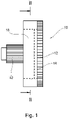
Figure 1 is a side view of an anti-back drive device embodying the present invention; -
Figure 2 is a cross-sectional view of the anti-back drive device shown inFigure 1 taken in the plane indicated by the line II-II inFigure 1 , in a first configuration of the parts thereof; -
Figure 3 is a cross-sectional view of the anti-back drive device shown inFigure 1 taken in the plane indicated by the line II-II inFigure 1 , in a second configuration of the parts thereof; and -
Figure 4 is a diagrammatic view of a hand prosthesis provided with the anti-back drive device as hown inFigures 1 to 3 . -
Figures 1 to 3 show ananti-back drive device 10 comprising adrive gear wheel 12 in the form of a plate constituting a drive member with gear teeth around its periphery and a circularprotruding drive portion 14 within its outer periphery. Fourpins 16 extend through respective through-holes (not shown) in and spaced circumferentially around thedrive portion 14 generally perpendicularly to thedrive gear wheel 12. - The
drive portion 14 is coupled to a driven member constituted by a circular drivenplate 18 by means of fourpins 20 received in respective holes (not shown) in thedrive portion 14 and extending in an axial direction intorespective slots 22 in the drivenplate 18 which are spaced apart uniformly therearound. W The length of eachslot 22 is slightly more than double the diameter of eachpin 20. - The driven
plate 18 is provided with fourcam recesses 24 spaced apart around its circumference. Each recess is bounded on one side by acam surface 26 constituted by a planar surface which, as viewed inFigures 2 and 3 , lies on an imaginary chord of an imaginary circle defined by the outer circumference of the drivenplate 18, with that part of the chord having one end lying on that circumference, and the other end being offset from the centre of the imaginary chord in the direction further from the end which lies on the circumference. A further planar boundingsurface 28 of eachrecess 24 extends from the said other end of the said part of the chord to the circumference of the drivenplate 18, perpendicularly to, or at least transversely of, thecam surface 26. -
Respective roller members 30 are provided in thecam recesses 24 with their roller axes parallel to the axis of thedevice 10. Eachroller member 30 is accommodated within locations towards the deeper end of its associatedcam recess 24, but will not fit within locations towards the shallower end thereof. Eachroller member 30 is in contact with aplunger 32 seated within aplunger recess 34 extending inwardly from and perpendicularly to the said furtherplanar bounding surface 28 of the associatedcam recess 24. Aresilient spring 35 is provided within eachplunger recess 34 to urge theplunger 32 towards its associatedroller member 30. InFigures 2 and 3 eachroller member 30 is at a location close to the deeper end of its associatedcam recess 24, so that it is accommodated by thecam recess 24 and is free to roll. - A
first pair 36 of thecam recesses 24 are located diametrically opposite one another and have their shallower ends displaced from their deeper ends in a clockwise direction around the circumference of the drivenplate 18. The remainingpair 38 of the cam recesses 24 are also located diametrically opposite one another, but with their shallower ends displaced from their deeper ends in an anticlockwise direction around the circumference of the drivenplate 18, and with the cam recesses 24 alternating from one pair to the other progressing around the circumference of the drivenplate 18. - The driven
plate 18 is surrounded by aring 40 with the circumference of the drivenplate 18 being concentric with but of slightly smaller radius than the inner surface of thering 40, so that eachroller member 30 lies between that inner surface and its associatedcam surface 26, and so that eachcam surface 26 also lies on an imaginary chord of an imaginary circle defined by the inner surface of thering 40. - The
pins 16 extend from thedrive portion 14 into respective ones of the cam recesses 24. Two of them are located so as to hold their associatedroller members 30 against their associatedplungers 32 with the latter being depressed into their respective plunger recesses 34, and the other two are spaced away from their associatedroller members 30 so that the associatedplungers 32 extend a little out of theirrespective recesses 34. - A driven
gear wheel 42 coaxial with thedrive gear wheel 12 is rotationally fixed relative to the drivenplate 18 by means of a key 44 on anaxle 46 fixed to the drivengear wheel 42, whichkey 44 is engaged within akeyway 48 in the drivenplate 18. Thedrive portion 14 and thedrive gear wheel 12 can freely rotate about theaxle 46. - In the relative configuration of the different parts of the
device 10 shown inFigure 2 , thepins 20 abut the ends of their associatedslots 22 which are displaced from their other ends in an anticlockwise sense around the drivenplate 18, so that viewing the drivenplate 18 as inFigure 2 , it is set to be driven by thedrive portion 14 in an anticlockwise sense. In this configuration, thepins 16 of thepair 36 of cam recesses 24 abut theirrespective roller members 30, and thepins 16 of thepair 38 have their associatedpins 16 spaced away from theirrespective roller members 30. As thedrive portion 14 drives the drivenplate 18 in an anticlockwise direction, theroller members 30 of thepair 38 are urged by any contact with thering 40 up against their associatedplungers 32, so that the latter push their roller members around thering 40 so that they remain within the deeper portions of their associated cam recesses 24 and are free to rotate. Theroller members 30 of theother pair 36 are held firmly against theirrespective plungers 32 at the deeper ends of the associated cam recesses by their associatedpins 16, and are also therefore free to rotate. This condition may be referred to as "driving forwards". However, in the event that rotation stops, and then a back drive acts on the drivenmember 18 in the clockwise sense, theroller members 30 of thepair 38 of cam recesses 24 are free to roll along their respective cam surfaces 26 towards the shallower ends of those cam recesses 24. Since they are already close to a location along their cam surfaces 26 in which there is insufficient space to accommodate them, by virtue of theplungers 32 acted upon by thesprings 35, they almost immediately become pinched between the inner surface of thering 40 and their associated cam surfaces 26, so that they jam the drivenplate 18 against rotation in the clockwise sense, and the device is effective as an anti-back drive against back drive of the drivenplate 18 in in this sense of rotation. This condition may be referred to as "backdriving forwards". - If the sense of rotation of the
drive portion 14 is now reversed, thepins 20 which are fixed relative to thedrive portion 14 shift to the opposite ends of theirrespective slots 22 as shown inFigure 3 . Thus the coupling between thedrive portion 14 and the drivenplate 18 is a free-play coupling, whereby this reversal in the sense of rotation of drive of the drivenplate 18 by thedrive portion 14 results in a disengagement of the coupling between those two parts as thepins 20 leave contact with respective ends of theirrespective slots 22, a predetermined relative rotation between those two parts as thepins 20 move towards the other ends of those slots so that thedrive portion 14 and the drivenplate 18 are disengaged from one another, and then a re-engagement between them as thepins 20 abut the other ends of theirrespective slots 22. Because thepins 16 are also fixed relative to thedrive portion 14, the rôles of thepins 16 of thefirst pair 36 of cam recesses 24 are reversed with those of thesecond pair 38. This condition may be referred to as "driving backwards", and the device now acts as an anti-back drive against back drive of the drivenmember 18 in the anticlockwise sense. Should there be forces which now urge the drivenmember 18 in the anticlockwise sense, they will be countered by the construction of the device. Such a condition may be referred to as "backdriving backwards". Thus thedevice 10 acts as a bi-directional anti-back drive. -
Figure 4 shows asimple hand prosthesis 50 fitted with ananti-back drive 10 as shown inFigures 1 to 3 . The hand prosthesis comprises a fixed wrist andthumb part 52 with afinger part 54 coupled to the wrist andthumb part 52 by way of apivot 56, so that thefinger part 54 can pivot relative to the wrist andthumb part 52 about thepivot 56, to move respective ends 58 and 60 of the thumb andwrist part 52 and thefinger part 54 towards or away from one another. Anelectric motor 62 is held within the wrist of the wrist andthumb part 52 and is coupled to drive thedrive gear 12 of theanti-back drive device 10. The drivengear 42 thereof engages agear 64 of ascrewthreaded spindle 66 having anut 68 which is moved up and down thespindle 66 according to the sense of rotation thereof. Arod 70 is connected byrespective pivots nut 68 and thefinger part 54 at a position spaced from thepivot 56. According to the sense ofrotation motor 62, and consequently theanti-back drive 10 and thespindle 66, thenut 68 will move up or down thespindle 66 to rotate thefinger part 54 and hence adjust the spacing between theends anti-back drive device 10. The manner in which the amputee can operate such a prosthesis is well known to those familiar with the art and will not therefore be described in detail here, save to say that one method is by way of a myoelectric sensor (not shown). - It will be appreciated that a relative positioning between the
drive portion 14 and the drivenplate 18 half-way between the positionings shown inFigures 2 and 3 respectively, constitutes a neutral drive position in which no drive is occurring. - Numerous variations in the construction of the illustrated device may occur to the reader without taking the resulting construction outside the scope of the present invention as in the appended claims. For example there may be more than four
cam recesses 24 with associatedroller members 30 and other parts. Theroller members 30 might be replaced by wedge parts (not shown) as alternative lock members. Whilst the surfaces of theroller members 30 and the inner surface of thering 40 are preferably plain, they may be textured or compliant surfaces. Plain solid roller members are preferred which resist wear and compression, buthollow roller members 30 with some degree of compliance may suit some applications. Thedevice 10 may be provided with sensors (not shown) to supervise its operation, drive forces and mechanical states being controlled, modified, displayed and/or recorded, and/or signals from the sensors being transmitted to other parts of a system (not shown) of which the device forms a part. Instead of a key 44 andkeyway 48 to lock the drivengear wheel 42 rotationally relative to the drivenplate 18, a locking pin (not shown) may be provided which extends through through-holes (not shown) in the drivengear wheel 42 and in the drivenplate 18.
Claims (14)
- An anti-back drive device (10) comprising a rotary drive member (12) coupled to a rotary driven member (18) to enable the rotary drive member (12) to drive the rotary driven member (18), the device (10) further comprising a ring (40) which surrounds the rotary driven member (18), the rotary driven member (18) being provided with at least two cam recesses (24) on its periphery containing respective lock members (30) between respective cam surfaces (26) of the cam recesses (24) and the said ring (40), each recess (24) being sufficiently deep towards one of its ends to accommodate its associated lock member (30) but not at locations towards its other end where the recess (24) is shallower relative to the ring (40), whereby drive of the driven member (18) by the drive member (12) will be permitted by each lock member (30) in a given sense of rotation of the driven member (18) relative to the ring (40) but each lock member (30) will inhibit back drive rotation of the driven member (18) in the opposite sense of rotation relative to the ring (40), in which the said at least two cam recesses (24) extend from their deeper to their shallower locations in opposite directions around the driven member (18), in which the coupling between the drive member (12) and the driven member (18) is a free-play coupling whereby a reversal in the sense of rotation of drive results in the disengagement of the coupling between those two members (12 and 18), a predetermined relative rotation between those two members (12 and 18) in which they are disengaged from one another, and then re-engagement between them, and in which respective protuberances (16) extend from the drive member (12) into the said at least two cam recesses (24) to retain one of the lock members (30) associated with one of those recesses (24) at the deeper location thereof whilst permitting movement of the other lock member (30) towards the shallower location of its associated recess (24), and, upon reversal of the sense of rotation of the driven member (18) by the drive member (12), to retain the said other of the said lock members (30) at the deeper location of its associated recess (24) whilst permitting movement of the said one of the lock members (30) towards the shallower location of its associated recess (24), so that the device (10) is a bi-directional anti-back drive device, characterised in that the device (10) further comprises respective plungers (32) seated in respective radially extending faces (28) of the cam recesses (24) which plungers (32) are acted upon by resilient parts (35) to urge the lock members (30) towards the shallower locations of the recesses (24).
- The anti-back drive device (10) according to claim 1, characterised in that each lock member (30) comprises a roller member (30).
- The anti-back drive device (10) according to claim 1 or claim 2, characterised in that each cam surface (26) lies on an imaginary chord of an imaginary circle defined by the ring (40).
- The anti-back drive device (10) according to any preceding claim, characterised in that the said protuberances (16) comprise respective pins (16) extending into the recesses (24) in an axial direction of the device (10), as defined by the axis of rotation thereof.
- The anti-back drive device (10) according to claim 4, characterised in that the pins (16) extend within holes provided in the drive member (12) to enable the pins (16) to be held therewithin.
- The anti-back drive device (10) according to claim 4 or claim 5, characterised in that the pins (16) are rotatable about their longitudinal axes.
- The anti-back drive device (10) according to any preceding claim, characterised in that the free-play coupling comprises at least one further protuberance (20) extending from the drive member (12) into a slot (22) in the driven member (18).
- The anti-back drive device (10) according to claim 7, characterised in that the slot (22) is arcuate.
- The anti-back drive device (10) according to claim 7 or claim 8, characterised in that the said at least one further protuberance (20) comprises a pin (20).
- The anti-back drive device (10) according to claim 9, characterised in that the pin (20) which constitutes the further protuberance (20) extends through an associated hole in the drive member (12).
- The anti-back drive device (10) according to any one of claims 7 to 10, characterised in that the said protuberances (16) are further from the central axis of the device (10) than the said at least one further protuberance (20).
- The anti-back drive device (10) according to any preceding claim, characterised in that the rotary driven member (18) is provided with four such cam recesses (24) spaced apart around its periphery, any and every two successive ones of those recesses progressing in a given sense around the periphery extending from their deeper to their shallower locations in opposite directions around the periphery.
- The anti-back drive device (10) according to any preceding claim, characterised in that the drive member (12) comprises a gear with teeth around its periphery.
- A prosthesis having the anti-back drive device (10) as claimed in any preceding claim.
Applications Claiming Priority (1)
| Application Number | Priority Date | Filing Date | Title |
|---|---|---|---|
| GBGB1917151.1A GB201917151D0 (en) | 2019-11-25 | 2019-11-25 | An anti-back drive device |
Publications (2)
| Publication Number | Publication Date |
|---|---|
| EP3825569A1 EP3825569A1 (en) | 2021-05-26 |
| EP3825569B1 true EP3825569B1 (en) | 2022-11-09 |
Family
ID=69137190
Family Applications (1)
| Application Number | Title | Priority Date | Filing Date |
|---|---|---|---|
| EP20207940.6A Active EP3825569B1 (en) | 2019-11-25 | 2020-11-17 | An anti-back drive device |
Country Status (6)
| Country | Link |
|---|---|
| US (1) | US11690736B2 (en) |
| EP (1) | EP3825569B1 (en) |
| DK (1) | DK3825569T3 (en) |
| FI (1) | FI3825569T3 (en) |
| GB (1) | GB201917151D0 (en) |
| PL (1) | PL3825569T3 (en) |
Family Cites Families (17)
| Publication number | Priority date | Publication date | Assignee | Title |
|---|---|---|---|---|
| US1529248A (en) * | 1924-03-26 | 1925-03-10 | W G Nagel Electric Company | Automatic clutch |
| GB409251A (en) | 1933-03-11 | 1934-04-26 | Carroll Hamilton Richards | Improvements in clutches and change-speed mechanisms |
| GB1355937A (en) | 1972-02-08 | 1974-06-12 | Wallis L S | Roller clutches |
| DE8620711U1 (en) * | 1986-08-01 | 1987-09-03 | No-Sag Drahtfedern Gmbh, 4835 Rietberg | Wheel for operating adjusting devices |
| CH673139A5 (en) | 1987-06-02 | 1990-02-15 | Mettler Instrumente Ag | |
| US5752590A (en) * | 1996-11-26 | 1998-05-19 | Lin; Ching Chou | Ratchet tool |
| EP1101967B1 (en) | 1998-08-03 | 2015-03-18 | Asmo Co. Ltd. | Clutch and drive device having the clutch |
| US6474457B2 (en) | 2000-10-19 | 2002-11-05 | Aichi Kikai Kogyo Kabushiki Kaisha | Bi-directional clutch |
| US7353930B2 (en) | 2005-02-10 | 2008-04-08 | Continental Automotive Systems Us, Inc. | Bi-directional friction clutch or brake assembly for transmissions |
| US7832542B2 (en) | 2005-04-07 | 2010-11-16 | Donghwan Byun | Reverse input prevent clutch bearing assembly |
| FR2889491B1 (en) * | 2005-08-05 | 2007-10-12 | Faurecia Sieges Automobile | AUTOBLOATING DEVICE FOR MOTOR VEHICLE SEAT |
| FR2917022B1 (en) * | 2007-06-08 | 2009-08-28 | Faurecia Sieges Automobile | MECHANISM FOR ADJUSTING A MOTOR VEHICLE |
| US20110092332A1 (en) | 2008-05-02 | 2011-04-21 | Evenson Roger A | Compact backdrive resistant transmission |
| EP2835550B1 (en) * | 2012-04-02 | 2019-05-08 | NTN Corporation | Rotation transmission device |
| JP6749539B2 (en) | 2015-02-12 | 2020-09-02 | アダマンド並木精密宝石株式会社 | Robot hand |
| EP3106698A1 (en) * | 2015-06-17 | 2016-12-21 | Phoenix Mecano Komponenten AG | Mechanical transmission with integrated load torque lock |
| DE102017120466B3 (en) | 2017-09-06 | 2018-08-30 | Otto Bock Healthcare Products Gmbh | Clamping roller locking |
-
2019
- 2019-11-25 GB GBGB1917151.1A patent/GB201917151D0/en not_active Ceased
-
2020
- 2020-11-17 PL PL20207940.6T patent/PL3825569T3/en unknown
- 2020-11-17 EP EP20207940.6A patent/EP3825569B1/en active Active
- 2020-11-17 FI FIEP20207940.6T patent/FI3825569T3/en active
- 2020-11-17 DK DK20207940.6T patent/DK3825569T3/en active
- 2020-11-18 US US16/951,097 patent/US11690736B2/en active Active
Also Published As
| Publication number | Publication date |
|---|---|
| GB201917151D0 (en) | 2020-01-08 |
| US20210154028A1 (en) | 2021-05-27 |
| DK3825569T3 (en) | 2022-12-19 |
| FI3825569T3 (en) | 2023-01-31 |
| US11690736B2 (en) | 2023-07-04 |
| EP3825569A1 (en) | 2021-05-26 |
| PL3825569T3 (en) | 2023-02-27 |
Similar Documents
| Publication | Publication Date | Title |
|---|---|---|
| JP5354186B2 (en) | Reduction gear | |
| EP0876558B1 (en) | Reversible, infinitely variable wedging element, force transfer device | |
| CN108884883B (en) | a flywheel mechanism | |
| EP3101314A1 (en) | Reduction gear with brake | |
| EP2539108B1 (en) | Roller bearing ratchet tool | |
| EP2835550B1 (en) | Rotation transmission device | |
| JP2014501894A (en) | Locked drive assembly for rotating parts | |
| EP2615323B1 (en) | Electric direct-acting actuator and electric disc brake device | |
| JP4159214B2 (en) | Reverse input prevention clutch | |
| US9618061B2 (en) | Clutch mechanism | |
| EP2833013B1 (en) | Clutch device | |
| CN107848446B (en) | Seat adjuster with additional locking member | |
| EP2416028A1 (en) | Electromagnetic clutch | |
| US11690736B2 (en) | Anti-back drive device | |
| EP4489697B1 (en) | Non-backdriving rotation transmission mechanism | |
| US20040144610A1 (en) | Gear coupler with a controllable roller clutch | |
| EP1605797B1 (en) | Clutch actuator surface apparatus and method | |
| KR20130024648A (en) | Pumping device of seat for vehicle | |
| KR101732373B1 (en) | Pumping device of seat for vehicle | |
| CN109937312B (en) | Clutch assembly | |
| JP2008121848A (en) | Reverse input prevention clutch | |
| JP3792971B2 (en) | Steering shaft locking device | |
| JP2572978Y2 (en) | A rotation transmission device that can rotate the output shaft by the input shaft | |
| EP3596352B1 (en) | Synchronizer for mechanical transmissions, particularly for vehicle transmissions | |
| KR20070101945A (en) | Reverse input clutch bearing assembly |
Legal Events
| Date | Code | Title | Description |
|---|---|---|---|
| PUAI | Public reference made under article 153(3) epc to a published international application that has entered the european phase |
Free format text: ORIGINAL CODE: 0009012 |
|
| STAA | Information on the status of an ep patent application or granted ep patent |
Free format text: STATUS: THE APPLICATION HAS BEEN PUBLISHED |
|
| AK | Designated contracting states |
Kind code of ref document: A1 Designated state(s): AL AT BE BG CH CY CZ DE DK EE ES FI FR GB GR HR HU IE IS IT LI LT LU LV MC MK MT NL NO PL PT RO RS SE SI SK SM TR |
|
| STAA | Information on the status of an ep patent application or granted ep patent |
Free format text: STATUS: REQUEST FOR EXAMINATION WAS MADE |
|
| 17P | Request for examination filed |
Effective date: 20211126 |
|
| RBV | Designated contracting states (corrected) |
Designated state(s): AL AT BE BG CH CY CZ DE DK EE ES FI FR GB GR HR HU IE IS IT LI LT LU LV MC MK MT NL NO PL PT RO RS SE SI SK SM TR |
|
| RIC1 | Information provided on ipc code assigned before grant |
Ipc: F16D 41/10 20060101AFI20220407BHEP |
|
| GRAP | Despatch of communication of intention to grant a patent |
Free format text: ORIGINAL CODE: EPIDOSNIGR1 |
|
| STAA | Information on the status of an ep patent application or granted ep patent |
Free format text: STATUS: GRANT OF PATENT IS INTENDED |
|
| INTG | Intention to grant announced |
Effective date: 20220602 |
|
| GRAS | Grant fee paid |
Free format text: ORIGINAL CODE: EPIDOSNIGR3 |
|
| GRAA | (expected) grant |
Free format text: ORIGINAL CODE: 0009210 |
|
| STAA | Information on the status of an ep patent application or granted ep patent |
Free format text: STATUS: THE PATENT HAS BEEN GRANTED |
|
| AK | Designated contracting states |
Kind code of ref document: B1 Designated state(s): AL AT BE BG CH CY CZ DE DK EE ES FI FR GB GR HR HU IE IS IT LI LT LU LV MC MK MT NL NO PL PT RO RS SE SI SK SM TR |
|
| REG | Reference to a national code |
Ref country code: GB Ref legal event code: FG4D |
|
| REG | Reference to a national code |
Ref country code: CH Ref legal event code: EP Ref country code: AT Ref legal event code: REF Ref document number: 1530551 Country of ref document: AT Kind code of ref document: T Effective date: 20221115 |
|
| REG | Reference to a national code |
Ref country code: DE Ref legal event code: R096 Ref document number: 602020006165 Country of ref document: DE |
|
| REG | Reference to a national code |
Ref country code: IE Ref legal event code: FG4D |
|
| REG | Reference to a national code |
Ref country code: DK Ref legal event code: T3 Effective date: 20221216 |
|
| REG | Reference to a national code |
Ref country code: FI Ref legal event code: FGE |
|
| REG | Reference to a national code |
Ref country code: SE Ref legal event code: TRGR |
|
| REG | Reference to a national code |
Ref country code: NO Ref legal event code: T2 Effective date: 20221109 Ref country code: LT Ref legal event code: MG9D |
|
| REG | Reference to a national code |
Ref country code: NL Ref legal event code: MP Effective date: 20221109 |
|
| REG | Reference to a national code |
Ref country code: AT Ref legal event code: MK05 Ref document number: 1530551 Country of ref document: AT Kind code of ref document: T Effective date: 20221109 |
|
| PG25 | Lapsed in a contracting state [announced via postgrant information from national office to epo] |
Ref country code: PT Free format text: LAPSE BECAUSE OF FAILURE TO SUBMIT A TRANSLATION OF THE DESCRIPTION OR TO PAY THE FEE WITHIN THE PRESCRIBED TIME-LIMIT Effective date: 20230309 Ref country code: LT Free format text: LAPSE BECAUSE OF FAILURE TO SUBMIT A TRANSLATION OF THE DESCRIPTION OR TO PAY THE FEE WITHIN THE PRESCRIBED TIME-LIMIT Effective date: 20221109 Ref country code: ES Free format text: LAPSE BECAUSE OF FAILURE TO SUBMIT A TRANSLATION OF THE DESCRIPTION OR TO PAY THE FEE WITHIN THE PRESCRIBED TIME-LIMIT Effective date: 20221109 Ref country code: AT Free format text: LAPSE BECAUSE OF FAILURE TO SUBMIT A TRANSLATION OF THE DESCRIPTION OR TO PAY THE FEE WITHIN THE PRESCRIBED TIME-LIMIT Effective date: 20221109 |
|
| PG25 | Lapsed in a contracting state [announced via postgrant information from national office to epo] |
Ref country code: RS Free format text: LAPSE BECAUSE OF FAILURE TO SUBMIT A TRANSLATION OF THE DESCRIPTION OR TO PAY THE FEE WITHIN THE PRESCRIBED TIME-LIMIT Effective date: 20221109 Ref country code: LV Free format text: LAPSE BECAUSE OF FAILURE TO SUBMIT A TRANSLATION OF THE DESCRIPTION OR TO PAY THE FEE WITHIN THE PRESCRIBED TIME-LIMIT Effective date: 20221109 Ref country code: HR Free format text: LAPSE BECAUSE OF FAILURE TO SUBMIT A TRANSLATION OF THE DESCRIPTION OR TO PAY THE FEE WITHIN THE PRESCRIBED TIME-LIMIT Effective date: 20221109 Ref country code: GR Free format text: LAPSE BECAUSE OF FAILURE TO SUBMIT A TRANSLATION OF THE DESCRIPTION OR TO PAY THE FEE WITHIN THE PRESCRIBED TIME-LIMIT Effective date: 20230210 |
|
| PG25 | Lapsed in a contracting state [announced via postgrant information from national office to epo] |
Ref country code: NL Free format text: LAPSE BECAUSE OF FAILURE TO SUBMIT A TRANSLATION OF THE DESCRIPTION OR TO PAY THE FEE WITHIN THE PRESCRIBED TIME-LIMIT Effective date: 20221109 |
|
| REG | Reference to a national code |
Ref country code: BE Ref legal event code: MM Effective date: 20221130 |
|
| PG25 | Lapsed in a contracting state [announced via postgrant information from national office to epo] |
Ref country code: SM Free format text: LAPSE BECAUSE OF FAILURE TO SUBMIT A TRANSLATION OF THE DESCRIPTION OR TO PAY THE FEE WITHIN THE PRESCRIBED TIME-LIMIT Effective date: 20221109 Ref country code: RO Free format text: LAPSE BECAUSE OF FAILURE TO SUBMIT A TRANSLATION OF THE DESCRIPTION OR TO PAY THE FEE WITHIN THE PRESCRIBED TIME-LIMIT Effective date: 20221109 Ref country code: IT Free format text: LAPSE BECAUSE OF NON-PAYMENT OF DUE FEES Effective date: 20221117 Ref country code: EE Free format text: LAPSE BECAUSE OF FAILURE TO SUBMIT A TRANSLATION OF THE DESCRIPTION OR TO PAY THE FEE WITHIN THE PRESCRIBED TIME-LIMIT Effective date: 20221109 Ref country code: CZ Free format text: LAPSE BECAUSE OF FAILURE TO SUBMIT A TRANSLATION OF THE DESCRIPTION OR TO PAY THE FEE WITHIN THE PRESCRIBED TIME-LIMIT Effective date: 20221109 |
|
| REG | Reference to a national code |
Ref country code: DE Ref legal event code: R097 Ref document number: 602020006165 Country of ref document: DE |
|
| PG25 | Lapsed in a contracting state [announced via postgrant information from national office to epo] |
Ref country code: SK Free format text: LAPSE BECAUSE OF FAILURE TO SUBMIT A TRANSLATION OF THE DESCRIPTION OR TO PAY THE FEE WITHIN THE PRESCRIBED TIME-LIMIT Effective date: 20221109 Ref country code: LU Free format text: LAPSE BECAUSE OF NON-PAYMENT OF DUE FEES Effective date: 20221117 Ref country code: AL Free format text: LAPSE BECAUSE OF FAILURE TO SUBMIT A TRANSLATION OF THE DESCRIPTION OR TO PAY THE FEE WITHIN THE PRESCRIBED TIME-LIMIT Effective date: 20221109 |
|
| PLBE | No opposition filed within time limit |
Free format text: ORIGINAL CODE: 0009261 |
|
| STAA | Information on the status of an ep patent application or granted ep patent |
Free format text: STATUS: NO OPPOSITION FILED WITHIN TIME LIMIT |
|
| 26N | No opposition filed |
Effective date: 20230810 |
|
| PG25 | Lapsed in a contracting state [announced via postgrant information from national office to epo] |
Ref country code: IE Free format text: LAPSE BECAUSE OF NON-PAYMENT OF DUE FEES Effective date: 20221117 |
|
| PG25 | Lapsed in a contracting state [announced via postgrant information from national office to epo] |
Ref country code: SI Free format text: LAPSE BECAUSE OF FAILURE TO SUBMIT A TRANSLATION OF THE DESCRIPTION OR TO PAY THE FEE WITHIN THE PRESCRIBED TIME-LIMIT Effective date: 20221109 Ref country code: BE Free format text: LAPSE BECAUSE OF NON-PAYMENT OF DUE FEES Effective date: 20221130 |
|
| PG25 | Lapsed in a contracting state [announced via postgrant information from national office to epo] |
Ref country code: IT Free format text: LAPSE BECAUSE OF NON-PAYMENT OF DUE FEES Effective date: 20221117 |
|
| PGRI | Patent reinstated in contracting state [announced from national office to epo] |
Ref country code: IT Effective date: 20221130 |
|
| PG25 | Lapsed in a contracting state [announced via postgrant information from national office to epo] |
Ref country code: CY Free format text: LAPSE BECAUSE OF FAILURE TO SUBMIT A TRANSLATION OF THE DESCRIPTION OR TO PAY THE FEE WITHIN THE PRESCRIBED TIME-LIMIT Effective date: 20221109 |
|
| PG25 | Lapsed in a contracting state [announced via postgrant information from national office to epo] |
Ref country code: MK Free format text: LAPSE BECAUSE OF FAILURE TO SUBMIT A TRANSLATION OF THE DESCRIPTION OR TO PAY THE FEE WITHIN THE PRESCRIBED TIME-LIMIT Effective date: 20221109 |
|
| PG25 | Lapsed in a contracting state [announced via postgrant information from national office to epo] |
Ref country code: MC Free format text: LAPSE BECAUSE OF FAILURE TO SUBMIT A TRANSLATION OF THE DESCRIPTION OR TO PAY THE FEE WITHIN THE PRESCRIBED TIME-LIMIT Effective date: 20221109 |
|
| PG25 | Lapsed in a contracting state [announced via postgrant information from national office to epo] |
Ref country code: MC Free format text: LAPSE BECAUSE OF FAILURE TO SUBMIT A TRANSLATION OF THE DESCRIPTION OR TO PAY THE FEE WITHIN THE PRESCRIBED TIME-LIMIT Effective date: 20221109 |
|
| REG | Reference to a national code |
Ref country code: CH Ref legal event code: PL |
|
| PG25 | Lapsed in a contracting state [announced via postgrant information from national office to epo] |
Ref country code: CH Free format text: LAPSE BECAUSE OF NON-PAYMENT OF DUE FEES Effective date: 20231130 |
|
| PG25 | Lapsed in a contracting state [announced via postgrant information from national office to epo] |
Ref country code: HU Free format text: LAPSE BECAUSE OF FAILURE TO SUBMIT A TRANSLATION OF THE DESCRIPTION OR TO PAY THE FEE WITHIN THE PRESCRIBED TIME-LIMIT; INVALID AB INITIO Effective date: 20201117 Ref country code: CH Free format text: LAPSE BECAUSE OF NON-PAYMENT OF DUE FEES Effective date: 20231130 Ref country code: BG Free format text: LAPSE BECAUSE OF FAILURE TO SUBMIT A TRANSLATION OF THE DESCRIPTION OR TO PAY THE FEE WITHIN THE PRESCRIBED TIME-LIMIT Effective date: 20221109 |
|
| PG25 | Lapsed in a contracting state [announced via postgrant information from national office to epo] |
Ref country code: MT Free format text: LAPSE BECAUSE OF FAILURE TO SUBMIT A TRANSLATION OF THE DESCRIPTION OR TO PAY THE FEE WITHIN THE PRESCRIBED TIME-LIMIT Effective date: 20221109 |
|
| PGFP | Annual fee paid to national office [announced via postgrant information from national office to epo] |
Ref country code: IS Payment date: 20251124 Year of fee payment: 6 Ref country code: DE Payment date: 20251126 Year of fee payment: 6 |
|
| PGFP | Annual fee paid to national office [announced via postgrant information from national office to epo] |
Ref country code: GB Payment date: 20251128 Year of fee payment: 6 |
|
| PGFP | Annual fee paid to national office [announced via postgrant information from national office to epo] |
Ref country code: NO Payment date: 20251124 Year of fee payment: 6 |
|
| PGFP | Annual fee paid to national office [announced via postgrant information from national office to epo] |
Ref country code: IT Payment date: 20251119 Year of fee payment: 6 Ref country code: FI Payment date: 20251124 Year of fee payment: 6 Ref country code: DK Payment date: 20251124 Year of fee payment: 6 |
|
| PGFP | Annual fee paid to national office [announced via postgrant information from national office to epo] |
Ref country code: FR Payment date: 20251124 Year of fee payment: 6 |
|
| PGFP | Annual fee paid to national office [announced via postgrant information from national office to epo] |
Ref country code: TR Payment date: 20251113 Year of fee payment: 6 |
|
| PGFP | Annual fee paid to national office [announced via postgrant information from national office to epo] |
Ref country code: SE Payment date: 20251124 Year of fee payment: 6 |
|
| PGFP | Annual fee paid to national office [announced via postgrant information from national office to epo] |
Ref country code: PL Payment date: 20251110 Year of fee payment: 6 |