EP3825565B1 - Method for manufacturing bushes and bushes - Google Patents
Method for manufacturing bushes and bushes Download PDFInfo
- Publication number
- EP3825565B1 EP3825565B1 EP20208991.8A EP20208991A EP3825565B1 EP 3825565 B1 EP3825565 B1 EP 3825565B1 EP 20208991 A EP20208991 A EP 20208991A EP 3825565 B1 EP3825565 B1 EP 3825565B1
- Authority
- EP
- European Patent Office
- Prior art keywords
- grooves
- bush
- pattern
- geometrical shapes
- longitudinal axis
- Prior art date
- Legal status (The legal status is an assumption and is not a legal conclusion. Google has not performed a legal analysis and makes no representation as to the accuracy of the status listed.)
- Revoked
Links
Images


Classifications
-
- F—MECHANICAL ENGINEERING; LIGHTING; HEATING; WEAPONS; BLASTING
- F16—ENGINEERING ELEMENTS AND UNITS; GENERAL MEASURES FOR PRODUCING AND MAINTAINING EFFECTIVE FUNCTIONING OF MACHINES OR INSTALLATIONS; THERMAL INSULATION IN GENERAL
- F16C—SHAFTS; FLEXIBLE SHAFTS; ELEMENTS OR CRANKSHAFT MECHANISMS; ROTARY BODIES OTHER THAN GEARING ELEMENTS; BEARINGS
- F16C33/00—Parts of bearings; Special methods for making bearings or parts thereof
- F16C33/02—Parts of sliding-contact bearings
- F16C33/04—Brasses; Bushes; Linings
- F16C33/06—Sliding surface mainly made of metal
- F16C33/10—Construction relative to lubrication
- F16C33/1025—Construction relative to lubrication with liquid, e.g. oil, as lubricant
- F16C33/106—Details of distribution or circulation inside the bearings, e.g. details of the bearing surfaces to affect flow or pressure of the liquid
- F16C33/1065—Grooves on a bearing surface for distributing or collecting the liquid
-
- F—MECHANICAL ENGINEERING; LIGHTING; HEATING; WEAPONS; BLASTING
- F16—ENGINEERING ELEMENTS AND UNITS; GENERAL MEASURES FOR PRODUCING AND MAINTAINING EFFECTIVE FUNCTIONING OF MACHINES OR INSTALLATIONS; THERMAL INSULATION IN GENERAL
- F16C—SHAFTS; FLEXIBLE SHAFTS; ELEMENTS OR CRANKSHAFT MECHANISMS; ROTARY BODIES OTHER THAN GEARING ELEMENTS; BEARINGS
- F16C17/00—Sliding-contact bearings for exclusively rotary movement
- F16C17/02—Sliding-contact bearings for exclusively rotary movement for radial load only
-
- F—MECHANICAL ENGINEERING; LIGHTING; HEATING; WEAPONS; BLASTING
- F16—ENGINEERING ELEMENTS AND UNITS; GENERAL MEASURES FOR PRODUCING AND MAINTAINING EFFECTIVE FUNCTIONING OF MACHINES OR INSTALLATIONS; THERMAL INSULATION IN GENERAL
- F16C—SHAFTS; FLEXIBLE SHAFTS; ELEMENTS OR CRANKSHAFT MECHANISMS; ROTARY BODIES OTHER THAN GEARING ELEMENTS; BEARINGS
- F16C33/00—Parts of bearings; Special methods for making bearings or parts thereof
- F16C33/02—Parts of sliding-contact bearings
- F16C33/04—Brasses; Bushes; Linings
- F16C33/06—Sliding surface mainly made of metal
- F16C33/10—Construction relative to lubrication
- F16C33/1025—Construction relative to lubrication with liquid, e.g. oil, as lubricant
- F16C33/103—Construction relative to lubrication with liquid, e.g. oil, as lubricant retained in or near the bearing
-
- F—MECHANICAL ENGINEERING; LIGHTING; HEATING; WEAPONS; BLASTING
- F16—ENGINEERING ELEMENTS AND UNITS; GENERAL MEASURES FOR PRODUCING AND MAINTAINING EFFECTIVE FUNCTIONING OF MACHINES OR INSTALLATIONS; THERMAL INSULATION IN GENERAL
- F16C—SHAFTS; FLEXIBLE SHAFTS; ELEMENTS OR CRANKSHAFT MECHANISMS; ROTARY BODIES OTHER THAN GEARING ELEMENTS; BEARINGS
- F16C33/00—Parts of bearings; Special methods for making bearings or parts thereof
- F16C33/02—Parts of sliding-contact bearings
- F16C33/04—Brasses; Bushes; Linings
- F16C33/06—Sliding surface mainly made of metal
- F16C33/14—Special methods of manufacture; Running-in
-
- F—MECHANICAL ENGINEERING; LIGHTING; HEATING; WEAPONS; BLASTING
- F16—ENGINEERING ELEMENTS AND UNITS; GENERAL MEASURES FOR PRODUCING AND MAINTAINING EFFECTIVE FUNCTIONING OF MACHINES OR INSTALLATIONS; THERMAL INSULATION IN GENERAL
- F16C—SHAFTS; FLEXIBLE SHAFTS; ELEMENTS OR CRANKSHAFT MECHANISMS; ROTARY BODIES OTHER THAN GEARING ELEMENTS; BEARINGS
- F16C2240/00—Specified values or numerical ranges of parameters; Relations between them
- F16C2240/40—Linear dimensions, e.g. length, radius, thickness, gap
- F16C2240/44—Hole or pocket sizes
-
- F—MECHANICAL ENGINEERING; LIGHTING; HEATING; WEAPONS; BLASTING
- F16—ENGINEERING ELEMENTS AND UNITS; GENERAL MEASURES FOR PRODUCING AND MAINTAINING EFFECTIVE FUNCTIONING OF MACHINES OR INSTALLATIONS; THERMAL INSULATION IN GENERAL
- F16C—SHAFTS; FLEXIBLE SHAFTS; ELEMENTS OR CRANKSHAFT MECHANISMS; ROTARY BODIES OTHER THAN GEARING ELEMENTS; BEARINGS
- F16C2352/00—Apparatus for drilling
Definitions
- the present invention relates to a method for manufacturing bushes and to bushes.
- Bushes are mechanical components of tubular shape with a cylindrical cross-section generally used for manufacturing high-fatigue-strength, turning kinematic pairs.
- the shape, material and size of a bush depend on the type of application.
- the present invention relates to bushes to be applied in construction machines, such as earthmoving machines or the like.
- bushes are used for the articulation of mechanical arms.
- bushes can also guarantee high mechanical strength. Therefore, bushes are particularly suitable for being installed at turning pairs which must have high fatigue strength.
- Bushes are known to comprise an internally hollow tubular body with a longitudinal axis.
- the tubular body is configured to be fitted, in use, on a shaft.
- a bush and a shaft are coupled so as to be mutually rotatable relative to each other, generally around the longitudinal axis of the bush, which, in use, is substantially coaxial with the axis of the shaft.
- bushes have one or more grease grooves made on the inner surface thereof, like for example in FR 2 121 259 A5 .
- Each grease groove is configured to house, in use, a lubricating material.
- Grooves of known types are generally made by means of machine tools for chip removal, for example by means of a lathe. It is known that a lathe comprises a cutting body which is slid longitudinally along the longitudinal axis of the bush, while a reciprocal rotation between the cutting body and the bush also takes place simultaneously. Therefore, in most cases, the inner grooves of a bush are helical in shape or extend along linear trajectories, along the longitudinal axis of the bush. This has several disadvantages, including:
- this type of solution has the disadvantage of creating weakening areas in the bush, in fact, at the recesses, the thickness of the bush is less than in other areas, for example at the grooves.
- this type of solution involves placing a greater quantity of lubricant at the recesses compared to the adjacent parts. This results in a difference between the bush and the shaft in the distribution of the lubricating material.
- Number 1 in Figure 1 indicates, as a whole, a bush 1 according to the present invention.
- the bush 1 comprises a tubular body 2 having a longitudinal axis X.
- the tubular body 2 of the bush 1 has a circular cross-section.
- the tubular body 2 is radially delimited, with respect to the longitudinal axis X, by an outer surface 3, an inner surface 4.
- the tubular body 2 is axially delimited along the longitudinal axis X by a head surface 5 and a back surface 6.
- the bush 1 has an inner cavity 7 which axially passes through the tubular body 2 and gives onto the outside of the tubular body 2 from the head surface 5 through a head opening 8, and from the back surface 6 through a back opening 9, respectively ( Figure 2 ).
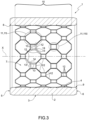
- the bush 1 according to the present invention has a pattern 10 (shown in greater detail in the shapes 2 to 6) on the inner surface 4.
- the pattern 10 is composed of the repetition of one or more geometrical shapes 11.
- the bush 1 comprises a plurality of patterns 10 formed in two respective areas of the bush 1.
- the number and arrangement of the patterns 10 can be different depending on the intended use of the bush 1.
- Each geometrical shape 11 is formed on the inner surface 4 of the bush 1.
- Each geometrical shape 11 is composed of one or more grooves 12.
- each geometrical shape 11 is composed of a plurality of grooves 12.
- each geometrical shape 11 is composed of a single groove 12. In other words, the groove 12 and the shape 11 coincide.
- Each groove 12 is substantially an area of the bush 1 of lesser thickness than a surrounding area.
- Each groove 12 may be rectilinear and/or curvilinear. In other words, each groove 12 has a straight, curved or mixed linear pattern.
- each groove 12 is rectilinear. According to the examples shown in Figures 11 to 13 , each groove 12 is curvilinear.
- each groove 12 is substantially a segment composing a corresponding side of the geometrical shape 11 itself.
- the grooves 12 are combined in a prefixed order.
- the grooves 12 of two adjacent geometrical shapes 11 coincide (i.e., two adjacent geometrical shapes 11 have the same groove 12 in common) or are at least partially in contact with each other.
- lubricating material may pass from a groove 12 of one geometrical shape 11 to the groove 12 of an adjacent geometrical shape 11 at an intersection area 13.
- the joining of the grooves 12 of three or more adjacent geometrical shapes 11 forms a junction 14, i.e., a discontinuity area.
- a junction 14 i.e., a discontinuity area.
- three adjacent geometrical shapes 11 form a junction 14 at which three grooves 12 are incident to each other.
- a geometrical shape 11 may be polygonal, i.e., have the shape of a polygon.
- the term polygonal/polygon is intended to mean: a geometrical shape which extends over a surface and is delimited by segments (in this case the grooves 12) arranged so that each one, excluding the first segment and the last segment, has one end in common with the preceding segment and the other end in common with the next segment.
- a groove 12 corresponds to a respective segment of the polygon.
- each geometrical shape 11 is a closed polygon.
- Closed polygon means a polygon in which the first and the last segment (or grooves 12) coincide with each other.
- the pattern 10 is composed of the repetition of a single geometrical shape 11.
- the geometrical shape 11 is a hexagon.
- the geometrical shape 11 can be another type of closed polygon with a different number of sides (greater than or equal to three sides).
- a geometrical shape 11 of the pattern 10 is a closed polygon with more than 4 sides, i.e., with five or more sides; this ensures the presence of at least one side which does not lie on a helical trajectory around the longitudinal axis X of the bush 1.
- the pattern 10 is composed of the repetition of two different geometrical shapes 11I and 11II.
- the pattern 10 is composed of the repetition of an octagon (11I) and a square (1111).
- the pattern 10 is composed of any combination of two different polygonal geometrical shapes 11.
- one geometrical shape 11 can be an open polygon.
- Open polygon means a polygon in which the first and the last segment (in this case the grooves 12) do not coincide with each other.
- the adjacent geometrical shapes 11 are not in contact with each other, i.e., they are not coincident and/or do not intersect with each other.
- the geometrical shape 11 is a star polygon.
- Star polygon means a star-shaped polygon.
- the star shape is generated by the intersection of several grooves 12.
- the junction 14 is created by the intersection/incidence of two or more grooves 12 of the same geometrical shape 11.
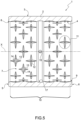
- Figure 5 shows a variant similar to Figure 4 , differing from Figure 4 in the angles of the grooves 12 of the geometrical shape 11 with respect to the longitudinal axis X of the bush 1.
- the pattern 10 is composed of two similar geometrical shapes 11, which differ from each other in the angles of the respective grooves 12 with respect to the longitudinal axis X of the bush 1.
- the pattern 10 is composed of the same polygonal star geometrical shape 11.
- each groove 12 forms an angle of approximately 45° or -45° with the longitudinal axis X of the bush.
- each groove 12 forms an angle of 0° or 90° with respect to the longitudinal axis X.
- the pattern 10 is composed of the repetition of three or more geometrical shapes 11 different from each other in terms of: type (open/closed/star-shaped polygon); and/or in the number of grooves 12 (or segments); and/or in the angles of the grooves 12 of each geometrical shape 11 with respect to the longitudinal axis X of the bush 1.
- the bush 1 can comprise, in a known way, a grease channel 15 which connects the inner cavity 7 to the outside.
- the grease channel 15 is a hole which radially and transversely passes through the tubular body 2 and connects the inner surface 4 to the outside.
- the bush 1 also has an outer annular gap 16 and an inner annular gap 17.
- the grease channel 15 passes through the tubular body 2 and, at one end, gives onto the inside of the outer annular gap 16, and at the other end, onto the inside of the inner annular gap 17.
- the outer annular gap 16 is configured, in use, to be put in communication with a source of lubricating material. In this case, greasing operations can be performed by feeding the lubricating material inside the pattern 10 through the outer annular gap 16, the grease channel 15 and the inner annular gap 17.
- the bush 1 can be devoid of the outer annular gap 16, in which case the lubricating material is introduced directly into the grease channel 15.
- the bush 1 lacks the inner annular gap 17, and the grease channel 15 is directly in communication with the pattern 10.
- At least one geometrical shape 11 has a groove 12I transverse to the longitudinal axis X, that is, following a circumferential trajectory coaxial with the longitudinal axis X and extending in a plane perpendicular to the axis X.
- a transverse groove 12I acts as an interruption of any flow of lubricating material along the longitudinal axis X.
- providing grooves 12 transverse to the longitudinal axis X allows, in use, better support to a shaft on which the bush 1 is fitted. In this case, advantageously, along the longitudinal axis X no large or wide areas are created along which the shaft is not supported by the bush 1.
- each geometrical shape 11 is composed of a single groove 12.
- each groove 12 extends parallel to the longitudinal axis X.
- the grooves 12 are rectilinear and have rounded ends. Two adjacent grooves 12 are in contact with each other substantially for the entire extension along the longitudinal axis X, in this way, advantageously, the pattern 10 is composed of an annular area, the extension of which along the longitudinal axis X is substantially a function of the length of the grooves 12.
- the bush 11 comprises one or more protrusions 20 protruding inside each pattern 10.
- the thickness of the bush 1 is increased to a predefined value.
- the bush 1 has a plurality of protrusions 20, which are identical to each other, uniformly distributed (with a quincunx distribution), and substantially cylindrical in shape.
- the number and shape of the protrusions can be different, in particular it can be noted that the protrusions of a same bush 1 may have geometrical shapes different from each other and different from those illustrated.
- each geometrical shape 11 is composed of a single circular groove 12.
- the pattern 10 of a bush 11 is composed of the repetition of a plurality of circular grooves 12.
- two adjacent grooves 12 are in contact with each other at an intersection area 13.
- a pattern could comprise a combination of both circular and linear grooves.
- a bush 1 of the type described above can be made by machining (for example, by means of a material removal process, and/or laser cutting) and/or by means of additive manufacturing techniques; and/or by overlapping a plurality of bent metal sheets; and/or by electro erosion.
- the method according to the present invention advantageously comprises creating on the inner surface 4 of the bush 1 a pattern 10 composed of one or more geometrical shapes 11.
- the method according to the present invention comprises creating patterns by the repetition of complex or closed and/or open and/or star-shaped polygonal geometrical shapes 11.
- the method according to the present invention can comprise, in a known way, thermal and/or chemical treatments of the bush 1 in any working step (before or after the creation of the pattern 10).
- a bush 1 according to the present invention advantageously has one or more patterns 10 composed of one or more complex or polygonal geometrical shapes 11.
- the grooves 12 of three or more adjacent polygonal geometrical shapes 11 cross each other at a junction 14, namely a discontinuity area.
- a junction 14 namely a discontinuity area.
- junctions 14 allows the creation of a crooked path for the lubricating material.
- the lubricating material is trapped inside the bush 1 to a greater extent, making its outflow more difficult. This has the advantage of extending the time between one maintenance activity and the next, while ensuring the correct operation of the bush 1.
- a pattern 10 of the type described above allows the working volume of the grooves 12 for housing the lubricating material to be increased, while maintaining the same surface area. This has the advantage of being able to distribute greater quantities of lubricating material with the same dimensions of the bush 1 and, consequently, to lengthen the time between one maintenance activity and the next.
- a pattern 10 of the type described above makes it possible to make grooves 12 which are less deep than the recesses currently used as a material reservoir. This makes it possible to guarantee, for the same geometrical dimensions and materials of which the bush 1 is made, a greater fatigue strength.
- the geometrical shapes 11 do not give onto the outside of the bush through the head surface 5 and the back surface 6.
- the grooves 12 are only formed inside the body of the bush 1. In this way, the flow of the lubricating material towards the outside is hindered.
- a method and a bush 1 according to the present invention can provide a product which, compared to the known bushes, can guarantee: a longer fatigue strength; a greater applicable amount of lubricating material; longer time between maintenance operations.
Landscapes
- Engineering & Computer Science (AREA)
- General Engineering & Computer Science (AREA)
- Mechanical Engineering (AREA)
- Chemical & Material Sciences (AREA)
- Oil, Petroleum & Natural Gas (AREA)
- Sliding-Contact Bearings (AREA)
- Insulators (AREA)
Description
- This patent application claims priority from
Italian patent application no. 102019000021780 filed on November 21, 2019 - The present invention relates to a method for manufacturing bushes and to bushes.
- Bushes are mechanical components of tubular shape with a cylindrical cross-section generally used for manufacturing high-fatigue-strength, turning kinematic pairs. The shape, material and size of a bush depend on the type of application.
- In particular, the present invention relates to bushes to be applied in construction machines, such as earthmoving machines or the like.
- Generally, in construction machines, bushes are used for the articulation of mechanical arms. In fact, in addition to being able to guarantee the rotation of one component relative to another, bushes can also guarantee high mechanical strength. Therefore, bushes are particularly suitable for being installed at turning pairs which must have high fatigue strength.
- Bushes are known to comprise an internally hollow tubular body with a longitudinal axis. The tubular body is configured to be fitted, in use, on a shaft.
- A bush and a shaft are coupled so as to be mutually rotatable relative to each other, generally around the longitudinal axis of the bush, which, in use, is substantially coaxial with the axis of the shaft.
- During rotation, the inner surface of the bush and the shaft rub against each other. To prevent seizure during use and ensure a longer life to the kinematic pair, it is advisable to apply a lubricating material to the inner surface of the bush which, in use, rubs against the shaft.
- It is known that bushes have one or more grease grooves made on the inner surface thereof, like for example in
FR 2 121 259 A5 - Grooves of known types are generally made by means of machine tools for chip removal, for example by means of a lathe. It is known that a lathe comprises a cutting body which is slid longitudinally along the longitudinal axis of the bush, while a reciprocal rotation between the cutting body and the bush also takes place simultaneously. Therefore, in most cases, the inner grooves of a bush are helical in shape or extend along linear trajectories, along the longitudinal axis of the bush. This has several disadvantages, including:
- the shapes of the grooves that can be created must extend along linear trajectories;
- the shape of the grooves favours the flow, during use, of the lubricating material towards the outside of the bush, therefore requiring frequent maintenance to grease the grooves.
- It is also known to provide bushes which have recesses (in place of or in addition to the grooves) to collect the lubricating material locally. This allows the creation of lubricating material collection areas to favour greater localized greasing and extend the period of time between one maintenance activity and the next.
- However, this type of solution has the disadvantage of creating weakening areas in the bush, in fact, at the recesses, the thickness of the bush is less than in other areas, for example at the grooves. Lastly, this type of solution involves placing a greater quantity of lubricant at the recesses compared to the adjacent parts. This results in a difference between the bush and the shaft in the distribution of the lubricating material.
- It is an object of the present invention to provide a method for manufacturing bushes, and bushes, which overcome the drawbacks described above.
- According to the present invention, there is provided a method as mentioned in the appended claims.
- According to the present invention, there is provided a bush as mentioned in the appended claims.
- The invention will now be described with reference to the accompanying drawings, which illustrate non-limiting embodiments thereof:
-
Figure 1 is a perspective view of a first example of a bush according to the present invention; -
Figure 2 is a longitudinal section of the bush inFigure 1 ; -
Figures 3 to 6 are similar toFigure 2 and show respective different examples of abush 1 according to the present invention; -
Figure 7 is similar toFigure 1 and shows a variant of thebush 1 inFigure 1 ; and -
Figure 8 is similar toFigure 7 and shows a further variant of thebush 1 inFigure 1 ; -
Figure 9 is a perspective view of a further variant of a bush not part of the present invention; -
Figure 10 is a longitudinal section of the bush inFigure 9 ; -
Figure 11 is an enlargement of an enlarged detail inFigure 10 ; -
Figure 12 is a perspective view of a further example, not part of the present invention; -
Figure 13 is a longitudinal section of the bush inFigure 12 ; and -
Figure 14 is an enlarged detail ofFigure 13 . -
Number 1 inFigure 1 indicates, as a whole, abush 1 according to the present invention. - The
bush 1 comprises atubular body 2 having a longitudinal axis X. In particular, thetubular body 2 of thebush 1 has a circular cross-section. Thetubular body 2 is radially delimited, with respect to the longitudinal axis X, by anouter surface 3, aninner surface 4. Thetubular body 2 is axially delimited along the longitudinal axis X by ahead surface 5 and aback surface 6. - The
bush 1 has aninner cavity 7 which axially passes through thetubular body 2 and gives onto the outside of thetubular body 2 from thehead surface 5 through a head opening 8, and from theback surface 6 through aback opening 9, respectively (Figure 2 ). - Advantageously, the
bush 1 according to the present invention has a pattern 10 (shown in greater detail in theshapes 2 to 6) on theinner surface 4. Thepattern 10 is composed of the repetition of one or moregeometrical shapes 11. - According to the examples shown in
Figures 5 to 14 , thebush 1 comprises a plurality ofpatterns 10 formed in two respective areas of thebush 1. According to the examples shown inFigures 5 to 14 , there are twopatterns 10 longitudinally separated by an innerannular gap 15, as will be better illustrated below. According to a variant, not shown, the number and arrangement of thepatterns 10 can be different depending on the intended use of thebush 1. - Each
geometrical shape 11 is formed on theinner surface 4 of thebush 1. - Each
geometrical shape 11 is composed of one ormore grooves 12. - According to the embodiment shown in
Figures 1 to 8 , eachgeometrical shape 11 is composed of a plurality ofgrooves 12. - According to the embodiment shown in
Figures 9 to 14 , eachgeometrical shape 11 is composed of asingle groove 12. In other words, thegroove 12 and theshape 11 coincide. - Each
groove 12 is substantially an area of thebush 1 of lesser thickness than a surrounding area. Eachgroove 12 may be rectilinear and/or curvilinear. In other words, eachgroove 12 has a straight, curved or mixed linear pattern. - According to the examples shown in
Figures 1 to 11 , eachgroove 12 is rectilinear. According to the examples shown inFigures 11 to 13 , eachgroove 12 is curvilinear. - According to the examples shown in
Figures 1 to 7 , eachgroove 12 is substantially a segment composing a corresponding side of thegeometrical shape 11 itself. For eachgeometrical shape 11, thegrooves 12 are combined in a prefixed order.
According to some embodiments (Figures 1 to 5 ,7-11 ), thegrooves 12 of two adjacentgeometrical shapes 11 coincide (i.e., two adjacentgeometrical shapes 11 have thesame groove 12 in common) or are at least partially in contact with each other. In other words, lubricating material may pass from agroove 12 of onegeometrical shape 11 to thegroove 12 of an adjacentgeometrical shape 11 at anintersection area 13. - Advantageously, the joining of the
grooves 12 of three or more adjacentgeometrical shapes 11 forms ajunction 14, i.e., a discontinuity area. According to the example shown inFigures 1 to 3 , three adjacentgeometrical shapes 11 form ajunction 14 at which threegrooves 12 are incident to each other. - According to the examples shown in
Figures 1 to 3 ,7 and8 , ageometrical shape 11 may be polygonal, i.e., have the shape of a polygon. The term polygonal/polygon is intended to mean: a geometrical shape which extends over a surface and is delimited by segments (in this case the grooves 12) arranged so that each one, excluding the first segment and the last segment, has one end in common with the preceding segment and the other end in common with the next segment. - According to the examples shown in
Figures 1 to 3 ,7 and8 , for a polygonalgeometrical shape 11, agroove 12 corresponds to a respective segment of the polygon. - According to the example shown in
shapes 1 to 3, eachgeometrical shape 11 is a closed polygon. Closed polygon means a polygon in which the first and the last segment (or grooves 12) coincide with each other. - According to the example shown in
shapes pattern 10 is composed of the repetition of a singlegeometrical shape 11. In particular, in the illustrated example, thegeometrical shape 11 is a hexagon. - According to a variant, not shown, the
geometrical shape 11 can be another type of closed polygon with a different number of sides (greater than or equal to three sides). - According to the examples shown in
Figures 1 to 3 ,7 and8 , ageometrical shape 11 of thepattern 10 is a closed polygon with more than 4 sides, i.e., with five or more sides; this ensures the presence of at least one side which does not lie on a helical trajectory around the longitudinal axis X of thebush 1. - According to the example shown in
Figure 3 , thepattern 10 is composed of the repetition of two different geometrical shapes 11I and 11II. In particular, in the example shown inFigure 3 , thepattern 10 is composed of the repetition of an octagon (11I) and a square (1111). - According to a variant, not shown, the
pattern 10 is composed of any combination of two different polygonalgeometrical shapes 11. - According to a variant, not shown, one
geometrical shape 11 can be an open polygon. Open polygon means a polygon in which the first and the last segment (in this case the grooves 12) do not coincide with each other. - According to the variant shown in
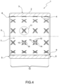
Figure 4 , the adjacentgeometrical shapes 11 are not in contact with each other, i.e., they are not coincident and/or do not intersect with each other. According to the variant shown inFigure 4 , thegeometrical shape 11 is a star polygon. Star polygon means a star-shaped polygon. In particular, the star shape is generated by the intersection ofseveral grooves 12. In the example shown inFigure 4 , thejunction 14 is created by the intersection/incidence of two ormore grooves 12 of the samegeometrical shape 11. -
Figure 5 shows a variant similar toFigure 4 , differing fromFigure 4 in the angles of thegrooves 12 of thegeometrical shape 11 with respect to the longitudinal axis X of thebush 1. - According to the variant shown in
Figure 6 , thepattern 10 is composed of two similargeometrical shapes 11, which differ from each other in the angles of therespective grooves 12 with respect to the longitudinal axis X of thebush 1. In particular, thepattern 10 is composed of the same polygonal stargeometrical shape 11. According to the example shown inFigure 4 , eachgroove 12 forms an angle of approximately 45° or -45° with the longitudinal axis X of the bush. According to the example shown inFigure 5 , eachgroove 12 forms an angle of 0° or 90° with respect to the longitudinal axis X. - According to a variant, not shown, the
pattern 10 is composed of the repetition of three or moregeometrical shapes 11 different from each other in terms of: type (open/closed/star-shaped polygon); and/or in the number of grooves 12 (or segments); and/or in the angles of thegrooves 12 of eachgeometrical shape 11 with respect to the longitudinal axis X of thebush 1. - According to the variant shown in
Figure 7 , thebush 1 can comprise, in a known way, agrease channel 15 which connects theinner cavity 7 to the outside. Thegrease channel 15 is a hole which radially and transversely passes through thetubular body 2 and connects theinner surface 4 to the outside. As shown, thebush 1 also has an outerannular gap 16 and an innerannular gap 17. Thegrease channel 15 passes through thetubular body 2 and, at one end, gives onto the inside of the outerannular gap 16, and at the other end, onto the inside of the innerannular gap 17. Advantageously and in a known manner, the outerannular gap 16 is configured, in use, to be put in communication with a source of lubricating material. In this case, greasing operations can be performed by feeding the lubricating material inside thepattern 10 through the outerannular gap 16, thegrease channel 15 and the innerannular gap 17. - Without losing generality, obviously, the
pattern 10 of thebush 1 shown inFigure 7 can be different from that illustrated (providing all the variants described above). - According to the example shown in
Figure 6 , thebush 1 can be devoid of the outerannular gap 16, in which case the lubricating material is introduced directly into thegrease channel 15. According to a variant, not shown, thebush 1 lacks the innerannular gap 17, and thegrease channel 15 is directly in communication with thepattern 10. - According to the variant shown in
Figure 8 , at least onegeometrical shape 11 has agroove 12I transverse to the longitudinal axis X, that is, following a circumferential trajectory coaxial with the longitudinal axis X and extending in a plane perpendicular to the axis X. In this way, advantageously, atransverse groove 12I acts as an interruption of any flow of lubricating material along the longitudinal axis X. Moreover, advantageously, providinggrooves 12 transverse to the longitudinal axis X allows, in use, better support to a shaft on which thebush 1 is fitted. In this case, advantageously, along the longitudinal axis X no large or wide areas are created along which the shaft is not supported by thebush 1. In other words, along the longitudinal axis X, the empty spaces between thebush 1 and the shaft are reduced. Therefore, this allows greater tightness between thebush 1 and the shaft and a more uniform distribution of the loads on the shaft during use, with the consequent improvement of the general conditions of use of the shaft. - Without losing generality, obviously, the
pattern 10 of thebush 1 shown inFigure 8 can be different from that illustrated (providing all the variants described above). - According to the example not part of the invention shown in
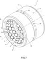
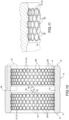
Figures 9 to 11 , eachgeometrical shape 11 is composed of asingle groove 12. In the example shown inFigures 9 to 11 , eachgroove 12 extends parallel to the longitudinal axis X. In the example shown, thegrooves 12 are rectilinear and have rounded ends. Twoadjacent grooves 12 are in contact with each other substantially for the entire extension along the longitudinal axis X, in this way, advantageously, thepattern 10 is composed of an annular area, the extension of which along the longitudinal axis X is substantially a function of the length of thegrooves 12. Advantageously, in the example shown inFigures 9 to 11 , thebush 11 comprises one ormore protrusions 20 protruding inside eachpattern 10. In this way, at eachprotrusion 20, the thickness of thebush 1 is increased to a predefined value. According to the example ofFigures 9 to 11 , thebush 1 has a plurality ofprotrusions 20, which are identical to each other, uniformly distributed (with a quincunx distribution), and substantially cylindrical in shape. - According to a variant, not shown, the number and shape of the protrusions can be different, in particular it can be noted that the protrusions of a
same bush 1 may have geometrical shapes different from each other and different from those illustrated. - According to the example shown in
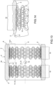
Figures 12 to 14 , eachgeometrical shape 11 is composed of a singlecircular groove 12. In particular, according to the example inFigures 12 to 14 , thepattern 10 of abush 11 is composed of the repetition of a plurality ofcircular grooves 12. - Advantageously, two
adjacent grooves 12 are in contact with each other at anintersection area 13. - According to a variant, not shown, a pattern could comprise a combination of both circular and linear grooves. A
bush 1 of the type described above can be made by machining (for example, by means of a material removal process, and/or laser cutting) and/or by means of additive manufacturing techniques; and/or by overlapping a plurality of bent metal sheets; and/or by electro erosion. - In any case, the method according to the present invention advantageously comprises creating on the
inner surface 4 of the bush 1 apattern 10 composed of one or moregeometrical shapes 11. In particular, advantageously, the method according to the present invention comprises creating patterns by the repetition of complex or closed and/or open and/or star-shaped polygonalgeometrical shapes 11. - Without losing generality, the method according to the present invention can comprise, in a known way, thermal and/or chemical treatments of the
bush 1 in any working step (before or after the creation of the pattern 10). - It follows from the above that a
bush 1 according to the present invention advantageously has one ormore patterns 10 composed of one or more complex or polygonalgeometrical shapes 11. - Advantageously, in case of
patterns 10 composed of adjacentgeometrical shapes 11, as in the examples shown inFigures 1 to 3 ,7 and8 , thegrooves 12 of three or more adjacent polygonalgeometrical shapes 11 cross each other at ajunction 14, namely a discontinuity area. In other words, there is no continuity between the grooves 12 (or sides) of three or more adjacent (polygonal) geometrical shapes 11. - Advantageously, the presence of
junctions 14 allows the creation of a crooked path for the lubricating material. In this way, advantageously, during use, the lubricating material is trapped inside thebush 1 to a greater extent, making its outflow more difficult. This has the advantage of extending the time between one maintenance activity and the next, while ensuring the correct operation of thebush 1. - Advantageously, a
pattern 10 of the type described above allows the working volume of thegrooves 12 for housing the lubricating material to be increased, while maintaining the same surface area. This has the advantage of being able to distribute greater quantities of lubricating material with the same dimensions of thebush 1 and, consequently, to lengthen the time between one maintenance activity and the next. - Advantageously, a
pattern 10 of the type described above makes it possible to makegrooves 12 which are less deep than the recesses currently used as a material reservoir. This makes it possible to guarantee, for the same geometrical dimensions and materials of which thebush 1 is made, a greater fatigue strength. - Advantageously, according to the examples shown in
Figures 9 to 14 , thegeometrical shapes 11 do not give onto the outside of the bush through thehead surface 5 and theback surface 6. In other words, thegrooves 12 are only formed inside the body of thebush 1. In this way, the flow of the lubricating material towards the outside is hindered. - Therefore, advantageously, a method and a
bush 1 according to the present invention can provide a product which, compared to the known bushes, can guarantee: a longer fatigue strength; a greater applicable amount of lubricating material; longer time between maintenance operations.
Claims (10)
- A method for manufacturing bushes (1) with a tubular body (2) having a longitudinal axis (X) and an inner cavity (7); each bush (1) having an inner surface (4) facing said inner cavity (7); wherein the method comprises creating on said inner surface (4) a pattern (10) composed of the repetition of one or more polygonal geometrical shapes (11); wherein each geometrical shape (11) is formed by means of a plurality of grooves (12; 12I), which are combined in a prefixed order; wherein the method comprises creating one or more junctions (14); each junction (14) being a discontinuity area given by the intersection of a plurality of grooves (12); the method being characterized in that each junction (14)- is generated by the intersection of the grooves (12) of three or more adjacent polygonal geometrical shapes (11), in particular there is discontinuity between the grooves(12; 12I) of three or more adjacent geometrical shapes (11); or- is generated by the intersection of the grooves (12) of a single geometrical shape (11) when the pattern (10) is composed of the repetition of one or more star geometrical shapes (11); wherein the grooves (12) of two adjacent geometrical shapes (11) are not in contact with each other.
- A method according to claim 1, wherein, in order to create a pattern (10), the method comprises delimiting, by means of one or more grooves (12), one or more protrusions (20); each protrusion (20) being configured to be put, in use, in contact with a shaft.
- A method according to any of the preceding claims, wherein a junction (14) is formed by a transversal groove (121), in particular a groove (12I) extending in a plane perpendicular to said longitudinal axis (X).
- A method according to any of the preceding claims, wherein, in order to create a pattern (10), the method comprises repeating a sequence of a plurality of polygonal geometrical shapes (11) different from each other in: type; and/or number of grooves (12); and/or angles of the respective grooves (12) with respect to said longitudinal axis (X).
- A method according to any of the preceding claims, wherein the pattern (10) is created by machining, in particular by means of a material removal process, and/or laser cutting and/or by means of additive manufacturing and/or by overlapping a plurality of bent metal sheets and/or electro erosion.
- A bush comprising a tubular body (2) and having a longitudinal axis (X), an inner cavity (7) and an inner surface (4) facing said inner cavity (7); wherein, the bush (1) has on said inner surface (4) a pattern (10) composed of the repetition of one or more polygonal geometrical shapes (11); wherein each geometrical shape (11) is realized by means of a plurality of grooves (12; 121), which are combined in a prefixed order; wherein the bush has one or more junctions (14); each junction (14) being a discontinuity area given by the intersection of a plurality of grooves (12); the bush being characterized in that each junction (14):- is generated by the intersection of the grooves (12) of three or more adjacent polygonal geometrical shapes (11), in particular there is discontinuity between the grooves (12; 12I) of three or more adjacent geometrical shapes (11); or,- is generated by the intersection of the grooves (12) of a single geometrical shape (11) when the pattern (10) is composed of the repetition of one or more star polygonal geometrical shapes (11); wherein the grooves (12) of two adjacent geometrical shapes (11) are not in contact with each other.
- A bush according to claim 6, wherein the pattern (10) is composed of the repetition of a plurality of polygonal geometrical shapes (11) different from each other in: type; and/or number of grooves (12); and/or angles of the respective grooves (12) with respect to said longitudinal axis (X).
- A bush according to claim 6 or 7, wherein the pattern (10) is composed of the repetition of a plurality of closed polygonal geometrical shapes (11); wherein at least one closed polygonal geometrical shape (11) comprises five or more grooves (12).
- A bush according to any claim from 6 to 8, wherein the pattern (10) comprises at least one transversal groove (121), in particular a groove (12I) extending in a plane perpendicular to said longitudinal axis (X).
- A bush according to any claim from 6 to 9, wherein the pattern (10) comprises at least one protrusion (20), which is delimited by one or more grooves (12) and is configured to be put, in use, in contact with a shaft.
Priority Applications (1)
| Application Number | Priority Date | Filing Date | Title |
|---|---|---|---|
| EP23175048.0A EP4219969A1 (en) | 2019-11-21 | 2020-11-20 | Method for manufacturing bushes and bushes |
Applications Claiming Priority (1)
| Application Number | Priority Date | Filing Date | Title |
|---|---|---|---|
| IT102019000021780A IT201900021780A1 (en) | 2019-11-21 | 2019-11-21 | METHOD FOR MANUFACTURING BUSHES AND BUSHES |
Related Child Applications (1)
| Application Number | Title | Priority Date | Filing Date |
|---|---|---|---|
| EP23175048.0A Division EP4219969A1 (en) | 2019-11-21 | 2020-11-20 | Method for manufacturing bushes and bushes |
Publications (3)
| Publication Number | Publication Date |
|---|---|
| EP3825565A1 EP3825565A1 (en) | 2021-05-26 |
| EP3825565B1 true EP3825565B1 (en) | 2023-06-07 |
| EP3825565C0 EP3825565C0 (en) | 2023-06-07 |
Family
ID=69904001
Family Applications (2)
| Application Number | Title | Priority Date | Filing Date |
|---|---|---|---|
| EP20208991.8A Revoked EP3825565B1 (en) | 2019-11-21 | 2020-11-20 | Method for manufacturing bushes and bushes |
| EP23175048.0A Pending EP4219969A1 (en) | 2019-11-21 | 2020-11-20 | Method for manufacturing bushes and bushes |
Family Applications After (1)
| Application Number | Title | Priority Date | Filing Date |
|---|---|---|---|
| EP23175048.0A Pending EP4219969A1 (en) | 2019-11-21 | 2020-11-20 | Method for manufacturing bushes and bushes |
Country Status (3)
| Country | Link |
|---|---|
| EP (2) | EP3825565B1 (en) |
| ES (1) | ES2947444T3 (en) |
| IT (1) | IT201900021780A1 (en) |
Families Citing this family (1)
| Publication number | Priority date | Publication date | Assignee | Title |
|---|---|---|---|---|
| JP6876766B2 (en) * | 2019-09-30 | 2021-05-26 | 大同メタル工業株式会社 | Half bearings and plain bearings |
Citations (8)
| Publication number | Priority date | Publication date | Assignee | Title |
|---|---|---|---|---|
| GB553673A (en) | 1941-11-25 | 1943-06-01 | Kigass Ltd | Bearings |
| FR2121259A5 (en) | 1971-01-07 | 1972-08-18 | Schmidt Gmbh Karl | |
| DE3326316C2 (en) | 1983-07-21 | 1987-07-02 | Schunk Industrieverwaltung Gmbh, 6301 Heuchelheim, De | |
| JP2002147456A (en) | 2000-11-08 | 2002-05-22 | Daido Metal Co Ltd | Sliding bearing |
| US20140023301A1 (en) | 2012-07-17 | 2014-01-23 | Us Synthetic Corporation | Bearing assemblies, apparatuses, and motor assemblies using the same |
| EP2703667A1 (en) | 2011-04-26 | 2014-03-05 | Senju Metal Industry Co., Ltd | Sliding member |
| EP2803874A1 (en) | 2013-05-13 | 2014-11-19 | Aktiebolaget SKF | Landing bearing and magnetic bearing assembly |
| JP2016180447A (en) | 2015-03-24 | 2016-10-13 | 株式会社クボタ | Engine bearing metal |
-
2019
- 2019-11-21 IT IT102019000021780A patent/IT201900021780A1/en unknown
-
2020
- 2020-11-20 EP EP20208991.8A patent/EP3825565B1/en not_active Revoked
- 2020-11-20 EP EP23175048.0A patent/EP4219969A1/en active Pending
- 2020-11-20 ES ES20208991T patent/ES2947444T3/en active Active
Patent Citations (8)
| Publication number | Priority date | Publication date | Assignee | Title |
|---|---|---|---|---|
| GB553673A (en) | 1941-11-25 | 1943-06-01 | Kigass Ltd | Bearings |
| FR2121259A5 (en) | 1971-01-07 | 1972-08-18 | Schmidt Gmbh Karl | |
| DE3326316C2 (en) | 1983-07-21 | 1987-07-02 | Schunk Industrieverwaltung Gmbh, 6301 Heuchelheim, De | |
| JP2002147456A (en) | 2000-11-08 | 2002-05-22 | Daido Metal Co Ltd | Sliding bearing |
| EP2703667A1 (en) | 2011-04-26 | 2014-03-05 | Senju Metal Industry Co., Ltd | Sliding member |
| US20140023301A1 (en) | 2012-07-17 | 2014-01-23 | Us Synthetic Corporation | Bearing assemblies, apparatuses, and motor assemblies using the same |
| EP2803874A1 (en) | 2013-05-13 | 2014-11-19 | Aktiebolaget SKF | Landing bearing and magnetic bearing assembly |
| JP2016180447A (en) | 2015-03-24 | 2016-10-13 | 株式会社クボタ | Engine bearing metal |
Non-Patent Citations (1)
| Title |
|---|
| UDDIN M.S., LIU Y.W.: "Design and optimization of a new geometric texture shape for the enhancement of hydrodynamic lubrication performance of parallel slider surfaces", BIOSURFACE AND BIOTRIBOLOGY, ELSEVIER, HOBOKEN, USA, vol. 2, no. 2, 1 June 2016 (2016-06-01), Hoboken, USA, pages 59 - 69, XP093185753, ISSN: 2405-4518, DOI: 10.1016/j.bsbt.2016.05.002 |
Also Published As
| Publication number | Publication date |
|---|---|
| ES2947444T3 (en) | 2023-08-09 |
| IT201900021780A1 (en) | 2021-05-21 |
| EP3825565A1 (en) | 2021-05-26 |
| EP4219969A1 (en) | 2023-08-02 |
| EP3825565C0 (en) | 2023-06-07 |
Similar Documents
| Publication | Publication Date | Title |
|---|---|---|
| EP2934801B1 (en) | Tool holder and machining tool with damping system | |
| EP3760351B1 (en) | Shrink-fit chuck with tool cooling | |
| EP2373898B1 (en) | Roller cage for a rolling bearing, particularly a double roller cage for a cylinder rolling bearing, rolling bearing, and method for producing a roller cage for a rolling bearing | |
| CN101688559A (en) | Rolling bearing cage assembled from several parts | |
| EP2635394B1 (en) | Gun drill | |
| EP2606248B1 (en) | Double roller cage for a double row cylinder roller bearing with mass compensation | |
| EP3825565B1 (en) | Method for manufacturing bushes and bushes | |
| EP1198325B1 (en) | Hollow piston for a piston engine and method for producing a hollow piston | |
| DE102008060374A1 (en) | damping sleeve | |
| JP6433393B2 (en) | Bearing and manufacturing method thereof | |
| DE102014014094A1 (en) | Chisel device and wear-resistant chisel for a ground milling machine | |
| JP2010175075A (en) | Rolling bearing cage | |
| KR20160006196A (en) | Twist drill and production method | |
| EP2811185B1 (en) | Flange sleeve | |
| WO2014135162A1 (en) | Cage portion and method for the production thereof | |
| HK40090402A (en) | Method for manufacturing bushes and bushes | |
| EP3250788B2 (en) | Pick, in particular a round-shank pick | |
| EP2595772B1 (en) | Structured sliding surface of a bearing shell | |
| EP4176706B1 (en) | Cutter blade for a chaff cutter and method for producing the same | |
| US5303468A (en) | Method of manufacturing a crankshaft | |
| WO2013053811A2 (en) | Tool system | |
| KR20120065355A (en) | Ball roller bearing | |
| EP3308892B1 (en) | Reamer | |
| EP2917487B1 (en) | Cutting ring for a cutting roller for quarrying and cutting roller for quarrying | |
| EP0462500B2 (en) | Housing for a rotary valve |
Legal Events
| Date | Code | Title | Description |
|---|---|---|---|
| PUAI | Public reference made under article 153(3) epc to a published international application that has entered the european phase |
Free format text: ORIGINAL CODE: 0009012 |
|
| STAA | Information on the status of an ep patent application or granted ep patent |
Free format text: STATUS: THE APPLICATION HAS BEEN PUBLISHED |
|
| AK | Designated contracting states |
Kind code of ref document: A1 Designated state(s): AL AT BE BG CH CY CZ DE DK EE ES FI FR GB GR HR HU IE IS IT LI LT LU LV MC MK MT NL NO PL PT RO RS SE SI SK SM TR |
|
| STAA | Information on the status of an ep patent application or granted ep patent |
Free format text: STATUS: REQUEST FOR EXAMINATION WAS MADE |
|
| 17P | Request for examination filed |
Effective date: 20211124 |
|
| RBV | Designated contracting states (corrected) |
Designated state(s): AL AT BE BG CH CY CZ DE DK EE ES FI FR GB GR HR HU IE IS IT LI LT LU LV MC MK MT NL NO PL PT RO RS SE SI SK SM TR |
|
| RIC1 | Information provided on ipc code assigned before grant |
Ipc: F16C 33/10 20060101AFI20220615BHEP |
|
| GRAP | Despatch of communication of intention to grant a patent |
Free format text: ORIGINAL CODE: EPIDOSNIGR1 |
|
| STAA | Information on the status of an ep patent application or granted ep patent |
Free format text: STATUS: GRANT OF PATENT IS INTENDED |
|
| INTG | Intention to grant announced |
Effective date: 20221007 |
|
| GRAS | Grant fee paid |
Free format text: ORIGINAL CODE: EPIDOSNIGR3 |
|
| GRAA | (expected) grant |
Free format text: ORIGINAL CODE: 0009210 |
|
| STAA | Information on the status of an ep patent application or granted ep patent |
Free format text: STATUS: THE PATENT HAS BEEN GRANTED |
|
| AK | Designated contracting states |
Kind code of ref document: B1 Designated state(s): AL AT BE BG CH CY CZ DE DK EE ES FI FR GB GR HR HU IE IS IT LI LT LU LV MC MK MT NL NO PL PT RO RS SE SI SK SM TR |
|
| REG | Reference to a national code |
Ref country code: GB Ref legal event code: FG4D |
|
| REG | Reference to a national code |
Ref country code: CH Ref legal event code: EP Ref country code: AT Ref legal event code: REF Ref document number: 1575919 Country of ref document: AT Kind code of ref document: T Effective date: 20230615 Ref country code: DE Ref legal event code: R096 Ref document number: 602020011778 Country of ref document: DE |
|
| U01 | Request for unitary effect filed |
Effective date: 20230613 |
|
| U07 | Unitary effect registered |
Designated state(s): AT BE BG DE DK EE FI FR IT LT LU LV MT NL PT SE SI Effective date: 20230621 |
|
| REG | Reference to a national code |
Ref country code: ES Ref legal event code: FG2A Ref document number: 2947444 Country of ref document: ES Kind code of ref document: T3 Effective date: 20230809 |
|
| REG | Reference to a national code |
Ref country code: LT Ref legal event code: MG9D |
|
| PG25 | Lapsed in a contracting state [announced via postgrant information from national office to epo] |
Ref country code: NO Free format text: LAPSE BECAUSE OF FAILURE TO SUBMIT A TRANSLATION OF THE DESCRIPTION OR TO PAY THE FEE WITHIN THE PRESCRIBED TIME-LIMIT Effective date: 20230907 |
|
| PG25 | Lapsed in a contracting state [announced via postgrant information from national office to epo] |
Ref country code: RS Free format text: LAPSE BECAUSE OF FAILURE TO SUBMIT A TRANSLATION OF THE DESCRIPTION OR TO PAY THE FEE WITHIN THE PRESCRIBED TIME-LIMIT Effective date: 20230607 Ref country code: HR Free format text: LAPSE BECAUSE OF FAILURE TO SUBMIT A TRANSLATION OF THE DESCRIPTION OR TO PAY THE FEE WITHIN THE PRESCRIBED TIME-LIMIT Effective date: 20230607 Ref country code: GR Free format text: LAPSE BECAUSE OF FAILURE TO SUBMIT A TRANSLATION OF THE DESCRIPTION OR TO PAY THE FEE WITHIN THE PRESCRIBED TIME-LIMIT Effective date: 20230908 |
|
| U20 | Renewal fee for the european patent with unitary effect paid |
Year of fee payment: 4 Effective date: 20231122 |
|
| PG25 | Lapsed in a contracting state [announced via postgrant information from national office to epo] |
Ref country code: SK Free format text: LAPSE BECAUSE OF FAILURE TO SUBMIT A TRANSLATION OF THE DESCRIPTION OR TO PAY THE FEE WITHIN THE PRESCRIBED TIME-LIMIT Effective date: 20230607 |
|
| PG25 | Lapsed in a contracting state [announced via postgrant information from national office to epo] |
Ref country code: IS Free format text: LAPSE BECAUSE OF FAILURE TO SUBMIT A TRANSLATION OF THE DESCRIPTION OR TO PAY THE FEE WITHIN THE PRESCRIBED TIME-LIMIT Effective date: 20231007 |
|
| PG25 | Lapsed in a contracting state [announced via postgrant information from national office to epo] |
Ref country code: SM Free format text: LAPSE BECAUSE OF FAILURE TO SUBMIT A TRANSLATION OF THE DESCRIPTION OR TO PAY THE FEE WITHIN THE PRESCRIBED TIME-LIMIT Effective date: 20230607 Ref country code: SK Free format text: LAPSE BECAUSE OF FAILURE TO SUBMIT A TRANSLATION OF THE DESCRIPTION OR TO PAY THE FEE WITHIN THE PRESCRIBED TIME-LIMIT Effective date: 20230607 Ref country code: RO Free format text: LAPSE BECAUSE OF FAILURE TO SUBMIT A TRANSLATION OF THE DESCRIPTION OR TO PAY THE FEE WITHIN THE PRESCRIBED TIME-LIMIT Effective date: 20230607 Ref country code: IS Free format text: LAPSE BECAUSE OF FAILURE TO SUBMIT A TRANSLATION OF THE DESCRIPTION OR TO PAY THE FEE WITHIN THE PRESCRIBED TIME-LIMIT Effective date: 20231007 Ref country code: CZ Free format text: LAPSE BECAUSE OF FAILURE TO SUBMIT A TRANSLATION OF THE DESCRIPTION OR TO PAY THE FEE WITHIN THE PRESCRIBED TIME-LIMIT Effective date: 20230607 |
|
| PG25 | Lapsed in a contracting state [announced via postgrant information from national office to epo] |
Ref country code: PL Free format text: LAPSE BECAUSE OF FAILURE TO SUBMIT A TRANSLATION OF THE DESCRIPTION OR TO PAY THE FEE WITHIN THE PRESCRIBED TIME-LIMIT Effective date: 20230607 |
|
| REG | Reference to a national code |
Ref country code: DE Ref legal event code: R026 Ref document number: 602020011778 Country of ref document: DE |
|
| PLBI | Opposition filed |
Free format text: ORIGINAL CODE: 0009260 |
|
| PLAX | Notice of opposition and request to file observation + time limit sent |
Free format text: ORIGINAL CODE: EPIDOSNOBS2 |
|
| 26 | Opposition filed |
Opponent name: KSB SE & CO. KGAA Effective date: 20240307 |
|
| REG | Reference to a national code |
Ref country code: CH Ref legal event code: PL |
|
| PG25 | Lapsed in a contracting state [announced via postgrant information from national office to epo] |
Ref country code: MC Free format text: LAPSE BECAUSE OF FAILURE TO SUBMIT A TRANSLATION OF THE DESCRIPTION OR TO PAY THE FEE WITHIN THE PRESCRIBED TIME-LIMIT Effective date: 20230607 |
|
| PG25 | Lapsed in a contracting state [announced via postgrant information from national office to epo] |
Ref country code: CH Free format text: LAPSE BECAUSE OF NON-PAYMENT OF DUE FEES Effective date: 20231130 |
|
| PLBB | Reply of patent proprietor to notice(s) of opposition received |
Free format text: ORIGINAL CODE: EPIDOSNOBS3 |
|
| PG25 | Lapsed in a contracting state [announced via postgrant information from national office to epo] |
Ref country code: MC Free format text: LAPSE BECAUSE OF FAILURE TO SUBMIT A TRANSLATION OF THE DESCRIPTION OR TO PAY THE FEE WITHIN THE PRESCRIBED TIME-LIMIT Effective date: 20230607 Ref country code: CH Free format text: LAPSE BECAUSE OF NON-PAYMENT OF DUE FEES Effective date: 20231130 |
|
| U20 | Renewal fee for the european patent with unitary effect paid |
Year of fee payment: 5 Effective date: 20241118 |
|
| PGFP | Annual fee paid to national office [announced via postgrant information from national office to epo] |
Ref country code: GB Payment date: 20241126 Year of fee payment: 5 |
|
| PGFP | Annual fee paid to national office [announced via postgrant information from national office to epo] |
Ref country code: ES Payment date: 20241218 Year of fee payment: 5 |
|
| RDAF | Communication despatched that patent is revoked |
Free format text: ORIGINAL CODE: EPIDOSNREV1 |
|
| PG25 | Lapsed in a contracting state [announced via postgrant information from national office to epo] |
Ref country code: CY Free format text: LAPSE BECAUSE OF FAILURE TO SUBMIT A TRANSLATION OF THE DESCRIPTION OR TO PAY THE FEE WITHIN THE PRESCRIBED TIME-LIMIT; INVALID AB INITIO Effective date: 20201120 |
|
| PG25 | Lapsed in a contracting state [announced via postgrant information from national office to epo] |
Ref country code: HU Free format text: LAPSE BECAUSE OF FAILURE TO SUBMIT A TRANSLATION OF THE DESCRIPTION OR TO PAY THE FEE WITHIN THE PRESCRIBED TIME-LIMIT; INVALID AB INITIO Effective date: 20201120 |
|
| RDAG | Patent revoked |
Free format text: ORIGINAL CODE: 0009271 |
|
| STAA | Information on the status of an ep patent application or granted ep patent |
Free format text: STATUS: PATENT REVOKED |
|
| PGFP | Annual fee paid to national office [announced via postgrant information from national office to epo] |
Ref country code: IE Payment date: 20250917 Year of fee payment: 6 |
|
| REG | Reference to a national code |
Ref country code: CH Ref legal event code: N12 Free format text: ST27 STATUS EVENT CODE: U-0-0-N10-N12 (AS PROVIDED BY THE NATIONAL OFFICE) Effective date: 20251022 |
|
| U20 | Renewal fee for the european patent with unitary effect paid |
Year of fee payment: 6 Effective date: 20251003 |
|
| 27W | Patent revoked |
Effective date: 20250910 |
|
| GBPR | Gb: patent revoked under art. 102 of the ep convention designating the uk as contracting state |
Effective date: 20250910 |
|
| PG25 | Lapsed in a contracting state [announced via postgrant information from national office to epo] |
Ref country code: TR Free format text: LAPSE BECAUSE OF FAILURE TO SUBMIT A TRANSLATION OF THE DESCRIPTION OR TO PAY THE FEE WITHIN THE PRESCRIBED TIME-LIMIT Effective date: 20230607 |