EP3825516B1 - Leitschaufelblattanordnung und entsprechendes montageverfahren - Google Patents
Leitschaufelblattanordnung und entsprechendes montageverfahren Download PDFInfo
- Publication number
- EP3825516B1 EP3825516B1 EP20208852.2A EP20208852A EP3825516B1 EP 3825516 B1 EP3825516 B1 EP 3825516B1 EP 20208852 A EP20208852 A EP 20208852A EP 3825516 B1 EP3825516 B1 EP 3825516B1
- Authority
- EP
- European Patent Office
- Prior art keywords
- airfoil
- radial
- piece
- spar
- platform
- Prior art date
- Legal status (The legal status is an assumption and is not a legal conclusion. Google has not performed a legal analysis and makes no representation as to the accuracy of the status listed.)
- Active
Links
Images


Classifications
-
- F—MECHANICAL ENGINEERING; LIGHTING; HEATING; WEAPONS; BLASTING
- F01—MACHINES OR ENGINES IN GENERAL; ENGINE PLANTS IN GENERAL; STEAM ENGINES
- F01D—NON-POSITIVE DISPLACEMENT MACHINES OR ENGINES, e.g. STEAM TURBINES
- F01D9/00—Stators
- F01D9/06—Fluid supply conduits to nozzles or the like
- F01D9/065—Fluid supply or removal conduits traversing the working fluid flow, e.g. for lubrication-, cooling-, or sealing fluids
-
- F—MECHANICAL ENGINEERING; LIGHTING; HEATING; WEAPONS; BLASTING
- F01—MACHINES OR ENGINES IN GENERAL; ENGINE PLANTS IN GENERAL; STEAM ENGINES
- F01D—NON-POSITIVE DISPLACEMENT MACHINES OR ENGINES, e.g. STEAM TURBINES
- F01D9/00—Stators
- F01D9/02—Nozzles; Nozzle boxes; Stator blades; Guide conduits, e.g. individual nozzles
- F01D9/04—Nozzles; Nozzle boxes; Stator blades; Guide conduits, e.g. individual nozzles forming ring or sector
- F01D9/041—Nozzles; Nozzle boxes; Stator blades; Guide conduits, e.g. individual nozzles forming ring or sector using blades
-
- F—MECHANICAL ENGINEERING; LIGHTING; HEATING; WEAPONS; BLASTING
- F01—MACHINES OR ENGINES IN GENERAL; ENGINE PLANTS IN GENERAL; STEAM ENGINES
- F01D—NON-POSITIVE DISPLACEMENT MACHINES OR ENGINES, e.g. STEAM TURBINES
- F01D5/00—Blades; Blade-carrying members; Heating, heat-insulating, cooling or antivibration means on the blades or the members
- F01D5/12—Blades
- F01D5/14—Form or construction
- F01D5/147—Construction, i.e. structural features, e.g. of weight-saving hollow blades
-
- F—MECHANICAL ENGINEERING; LIGHTING; HEATING; WEAPONS; BLASTING
- F01—MACHINES OR ENGINES IN GENERAL; ENGINE PLANTS IN GENERAL; STEAM ENGINES
- F01D—NON-POSITIVE DISPLACEMENT MACHINES OR ENGINES, e.g. STEAM TURBINES
- F01D9/00—Stators
- F01D9/02—Nozzles; Nozzle boxes; Stator blades; Guide conduits, e.g. individual nozzles
- F01D9/04—Nozzles; Nozzle boxes; Stator blades; Guide conduits, e.g. individual nozzles forming ring or sector
- F01D9/042—Nozzles; Nozzle boxes; Stator blades; Guide conduits, e.g. individual nozzles forming ring or sector fixing blades to stators
-
- B—PERFORMING OPERATIONS; TRANSPORTING
- B28—WORKING CEMENT, CLAY, OR STONE
- B28B—SHAPING CLAY OR OTHER CERAMIC COMPOSITIONS; SHAPING SLAG; SHAPING MIXTURES CONTAINING CEMENTITIOUS MATERIAL, e.g. PLASTER
- B28B11/00—Apparatus or processes for treating or working the shaped or preshaped articles
- B28B11/003—Apparatus or processes for treating or working the shaped or preshaped articles the shaping of preshaped articles, e.g. by bending
- B28B11/006—Making hollow articles or partly closed articles
-
- F—MECHANICAL ENGINEERING; LIGHTING; HEATING; WEAPONS; BLASTING
- F01—MACHINES OR ENGINES IN GENERAL; ENGINE PLANTS IN GENERAL; STEAM ENGINES
- F01D—NON-POSITIVE DISPLACEMENT MACHINES OR ENGINES, e.g. STEAM TURBINES
- F01D5/00—Blades; Blade-carrying members; Heating, heat-insulating, cooling or antivibration means on the blades or the members
- F01D5/12—Blades
- F01D5/28—Selecting particular materials; Particular measures relating thereto; Measures against erosion or corrosion
- F01D5/282—Selecting composite materials, e.g. blades with reinforcing filaments
-
- F—MECHANICAL ENGINEERING; LIGHTING; HEATING; WEAPONS; BLASTING
- F01—MACHINES OR ENGINES IN GENERAL; ENGINE PLANTS IN GENERAL; STEAM ENGINES
- F01D—NON-POSITIVE DISPLACEMENT MACHINES OR ENGINES, e.g. STEAM TURBINES
- F01D5/00—Blades; Blade-carrying members; Heating, heat-insulating, cooling or antivibration means on the blades or the members
- F01D5/12—Blades
- F01D5/28—Selecting particular materials; Particular measures relating thereto; Measures against erosion or corrosion
- F01D5/284—Selection of ceramic materials
-
- F—MECHANICAL ENGINEERING; LIGHTING; HEATING; WEAPONS; BLASTING
- F05—INDEXING SCHEMES RELATING TO ENGINES OR PUMPS IN VARIOUS SUBCLASSES OF CLASSES F01-F04
- F05D—INDEXING SCHEME FOR ASPECTS RELATING TO NON-POSITIVE-DISPLACEMENT MACHINES OR ENGINES, GAS-TURBINES OR JET-PROPULSION PLANTS
- F05D2240/00—Components
- F05D2240/10—Stators
- F05D2240/12—Fluid guiding means, e.g. vanes
-
- F—MECHANICAL ENGINEERING; LIGHTING; HEATING; WEAPONS; BLASTING
- F05—INDEXING SCHEMES RELATING TO ENGINES OR PUMPS IN VARIOUS SUBCLASSES OF CLASSES F01-F04
- F05D—INDEXING SCHEME FOR ASPECTS RELATING TO NON-POSITIVE-DISPLACEMENT MACHINES OR ENGINES, GAS-TURBINES OR JET-PROPULSION PLANTS
- F05D2240/00—Components
- F05D2240/80—Platforms for stationary or moving blades
-
- F—MECHANICAL ENGINEERING; LIGHTING; HEATING; WEAPONS; BLASTING
- F05—INDEXING SCHEMES RELATING TO ENGINES OR PUMPS IN VARIOUS SUBCLASSES OF CLASSES F01-F04
- F05D—INDEXING SCHEME FOR ASPECTS RELATING TO NON-POSITIVE-DISPLACEMENT MACHINES OR ENGINES, GAS-TURBINES OR JET-PROPULSION PLANTS
- F05D2300/00—Materials; Properties thereof
- F05D2300/60—Properties or characteristics given to material by treatment or manufacturing
- F05D2300/603—Composites; e.g. fibre-reinforced
- F05D2300/6033—Ceramic matrix composites [CMC]
-
- Y—GENERAL TAGGING OF NEW TECHNOLOGICAL DEVELOPMENTS; GENERAL TAGGING OF CROSS-SECTIONAL TECHNOLOGIES SPANNING OVER SEVERAL SECTIONS OF THE IPC; TECHNICAL SUBJECTS COVERED BY FORMER USPC CROSS-REFERENCE ART COLLECTIONS [XRACs] AND DIGESTS
- Y02—TECHNOLOGIES OR APPLICATIONS FOR MITIGATION OR ADAPTATION AGAINST CLIMATE CHANGE
- Y02T—CLIMATE CHANGE MITIGATION TECHNOLOGIES RELATED TO TRANSPORTATION
- Y02T50/00—Aeronautics or air transport
- Y02T50/60—Efficient propulsion technologies, e.g. for aircraft
Definitions
- the present invention relates to a vane airfoil assembly as well as to a method of assembling a vane.
- US 2004/120811 A1 describes a method for securing a nozzle for a turbine.
- the nozzle includes an airfoil having a suction side and a pressure side connected at a leading edge and a trailing edge such that a cooling cavity is defined within the airfoil, the airfoil extending between an inner band and an outer band.
- the method includes extending at least one member through the airfoil, and at least one of the inner band and the outer band.
- the method further includes securing the nozzle assembly in position with at least one fastener such that the at least one member is coupled adjacent to at least one of the inner band and the outer band.
- US 2010/162717 A1 describes a hot section component of a gas turbine engine having a covering.
- the covering includes a protrusion and is attached to the hot section component through a flexible retainer.
- the covering is made from ceramic matrix composite.
- the flexible retainer has a closed position and an open position. The retainer secures the protrusion to the hot section component when it engages part of the protrusion when in the closed position.
- US 2013/004296 A1 describes a segmented component for use with a gas turbine engine comprising a radially extending gas path portion.
- the gas path portion is for interacting with gas flow from the gas turbine engine.
- the gas path portion comprises a forward portion forming a leading edge of a stationary vane, an aft portion forming a trailing edge of the stationary vane, and a plurality of middle portions forming a pressure side and a suction side of the stationary vane.
- the component is divided into axially aligned segments comprising a forward segment, an aft segment, and a plurality of middle segments disposed between the forward segment and the aft segment.
- the middle segments comprise radially elongate ceramic matrix composite material plates.
- the pocket includes at least one mating feature which is configured to mate with the at least one radial tab.
- the spar piece is metallic and the airfoil piece is ceramic matrix composite.
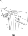
- the radial tabs 75 have a radial extent d2.
- the radial extent d2 is less than the radial extent d1 of the collar projection 74.
- the ratio of the radial extents d1:d2 is between about 1:1 and 1:5.
- Each of the radial tabs 75 also has a circumferential extent c.
- a cumulative circumferential extent is defined as the sum of the circumferential extent c of each of the tabs 75.
- the cumulative circumferential percent of the radial tabs 75 is between about 20 and 40% of the circumferential extent of the collar projection 74.
- the radial tabs 75 also have a surface area which is the product of the radial extent d2 and the circumferential extent c.
- a cumulative surface area is defined as the sum of the surface area of each of the tabs 75.
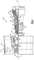
- the airfoil piece 62 is formed of CMC plies 100a/100b ( Figure 3 ). Though two plies are schematically shown, more plies could be used. For example, additional plies could be used as an outer wrap around the plies 100a/100b, and/or additional plies could be used to define the cavities 72.
- the CMC plies 100a/100b are continuous through the airfoil section 70 and the collar projection 74.
- the continuous plies 100a/100b improve the strength of the airfoil section 70 and collar projection 74.
- the airfoil piece 62 withstands and transfers loads directly to the spar piece 64 as discussed above.
- the plies can be layed up, consolidated, and cured as would generally be known in the art.
- the collar projection 74 and tabs 75 fill substantially all of the radial extent of the pocket 80 in the spar platform 76.
- the pocket 80 in the spar platform 76 includes mating features 84 which mate with the tabs 75. The mating features 84 locate the tabs 75 and collar projection 74 with respect to the pocket 80. The mating features 84 also are configured to support the tabs 75 within the pocket 80.
- the vane 60 is assembled by inserting the spar piece 64 into the airfoil piece 62.
- the assembly includes aligning the pocket 80 with the collar projection 74 (and optionally the mating features 84 with the tabs 75) such that the collar projection 74 extends into the pocket 80 when the vanes 60 are assembled.
Landscapes
- Engineering & Computer Science (AREA)
- Mechanical Engineering (AREA)
- General Engineering & Computer Science (AREA)
- Architecture (AREA)
- Physics & Mathematics (AREA)
- Fluid Mechanics (AREA)
- Structures Of Non-Positive Displacement Pumps (AREA)
Claims (13)
- Leitschaufelblattanordnung, umfassend:
ein Schaufelblattstück (62), umfassend:eine erste Schaufelblattplattform (66);eine zweite Schaufelblattplattform (68); undeinen hohlen Schaufelblattabschnitt (70), der die erste Schaufelblattplattform (66) und die zweite Schaufelblattplattform (68) verbindet, wobei der hohle Schaufelblattabschnitt (70) einen Kragenvorsprung (74) beinhaltet, der sich über die erste Schaufelblattplattform (66) hinaus erstreckt, wobei der Kragenvorsprung (74) mindestens eine davon vorstehende radiale Lasche (75) beinhaltet;ein Holmstück (64) definiert eine Holmplattform (76) und ein Holm erstreckt sich von der Holmplattform (76) in den hohlen Schaufelblattabschnitt (70), wobei das Holmstück (64) eine radiale Tasche (80) beinhaltet, die durch eine erste und eine zweite gegenüberliegende Fläche definiert ist, wobei die radiale Tasche (80) dazu konfiguriert ist, den Kragenvorsprung (74) aufzunehmen, unddadurch gekennzeichnet, dass:
das hohle Schaufelblatt (70) einen ersten und einen zweiten Hohlraum (72) beinhaltet, die durch eine Trennwand (73) getrennt sind, und wobei sich die mindestens eine radiale Lasche (75) an einer Umfangsstelle des Kragenvorsprungs (74) befindet, die einer Stelle der Trennwand (73) entspricht. - Leitschaufelblattanordnung nach Anspruch 1, wobei der Kragenvorsprung (74) eine erste radiale Ausdehnung (d1) von der Plattform (66) aus aufweist und die mindestens eine radiale Lasche (75) eine zweite radiale Ausdehnung (d2) von dem Kragenvorsprung (74) aus aufweist und ein Verhältnis der ersten radialen Ausdehnung (d1) zu der zweiten radialen Ausdehnung (d2) zwischen etwa 1:1 und 1:5 liegt.
- Leitschaufelblattanordnung nach Anspruch 1 oder 2, wobei die mindestens eine radiale Lasche (75) eine Vielzahl von radialen Laschen (75) umfasst und die Vielzahl von radialen Laschen (75) eine kumulative Umfangsausdehnung (c) aufweist.
- Leitschaufelblattanordnung nach Anspruch 3, wobei die kumulative Umfangsausdehnung (c) zwischen etwa 20 und 40 % einer Umfangsausdehnung des Kragenvorsprungs (74) beträgt.
- Leitschaufelblattanordnung nach einem der Ansprüche 1 bis 4, wobei der Schaufelblattabschnitt (70) und der Kragenvorsprung (74) mindestens eine durchgehende Verbundwerkstofflage mit keramischer Matrix beinhalten.
- Leitschaufelblattanordnung nach einem der Ansprüche 1 bis 5, wobei der hohle Schaufelblattabschnitt (70) dazu konfiguriert ist, ein metallisches Holmstück (64) darin aufzunehmen.
- Leitschaufelblattanordnung nach einem der Ansprüche 1 bis 6, wobei der Kragenvorsprung (74) ein radial äußerer Kragenvorsprung (74) ist.
- Leitschaufelblattanordnung nach einem der Ansprüche 1 bis 7, wobei das Holmstück (64) dazu konfiguriert ist, strukturelle Lasten von dem Leitschaufelblattstück (62) über den Kragenvorsprung (74) auf eine Trägerstruktur zu übertragen.
- Leitschaufelblattanordnung nach einem der Ansprüche 1 bis 8, wobei die radiale Tasche (80) mindestens ein Passmerkmal (84) beinhaltet, das zum Passen mit der mindestens einen radialen Lasche (75) konfiguriert ist.
- Verfahren zum Montieren einer Leitschaufel, umfassend:
Einsetzen eines Holmstücks (64) in einen Hohlraum eines hohlen Schaufelblattabschnitts (70) einer Leitschaufelblattanordnung nach einem der Ansprüche 1 bis 9. - Verfahren nach Anspruch 10, wobei das Einsetzen Ausrichten einer Tasche (80) in einer Holmplattform (76) des Holmstücks (64) mit dem Kragenvorsprung (74) beinhaltet.
- Verfahren nach Anspruch 11, wobei die Tasche (80) mindestens ein Passmerkmal (84) beinhaltet, das zum Passen mit der mindestens einen radialen Lasche (75) konfiguriert ist.
- Leitschaufelblattanordnung nach einem der Ansprüche 1 bis 9 oder Verfahren nach einem der Ansprüche 10 bis 12, wobei das Holmstück (64) metallisch ist und das Schaufelblattstück (62) ein Verbundwerkstoff mit keramischer Matrix ist.
Applications Claiming Priority (1)
| Application Number | Priority Date | Filing Date | Title |
|---|---|---|---|
| US16/690,989 US11242762B2 (en) | 2019-11-21 | 2019-11-21 | Vane with collar |
Publications (2)
| Publication Number | Publication Date |
|---|---|
| EP3825516A1 EP3825516A1 (de) | 2021-05-26 |
| EP3825516B1 true EP3825516B1 (de) | 2025-01-01 |
Family
ID=73543077
Family Applications (1)
| Application Number | Title | Priority Date | Filing Date |
|---|---|---|---|
| EP20208852.2A Active EP3825516B1 (de) | 2019-11-21 | 2020-11-20 | Leitschaufelblattanordnung und entsprechendes montageverfahren |
Country Status (2)
| Country | Link |
|---|---|
| US (1) | US11242762B2 (de) |
| EP (1) | EP3825516B1 (de) |
Families Citing this family (3)
| Publication number | Priority date | Publication date | Assignee | Title |
|---|---|---|---|---|
| US11530614B2 (en) * | 2021-02-19 | 2022-12-20 | Raytheon Technologies Corporation | Vane arc segment formed of fiber-reinforced composite |
| US11952918B2 (en) * | 2022-07-20 | 2024-04-09 | Ge Infrastructure Technology Llc | Cooling circuit for a stator vane braze joint |
| US12241374B2 (en) | 2023-05-10 | 2025-03-04 | Rolls-Royce Corporation | Ceramic matrix composite endwall sealing around vane airfoil of gas turbine engine |
Citations (1)
| Publication number | Priority date | Publication date | Assignee | Title |
|---|---|---|---|---|
| EP3730739A1 (de) * | 2019-04-23 | 2020-10-28 | Rolls-Royce plc | Turbinenaanordnung für ein gasturbinentriebwerk mit verbundstoffleitschaufel mit keramischer matrix |
Family Cites Families (41)
| Publication number | Priority date | Publication date | Assignee | Title |
|---|---|---|---|---|
| US730363A (en) * | 1902-08-21 | 1903-06-09 | Gen Electric | Detachable turbine-bucket. |
| US1547838A (en) * | 1923-03-30 | 1925-07-28 | Gen Electric | Turbine element and method of making the same |
| US2110679A (en) * | 1936-04-22 | 1938-03-08 | Gen Electric | Elastic fluid turbine |
| US2925998A (en) * | 1952-12-22 | 1960-02-23 | Gen Motors Corp | Turbine nozzles |
| US4464094A (en) * | 1979-05-04 | 1984-08-07 | Trw Inc. | Turbine engine component and method of making the same |
| US5332360A (en) * | 1993-09-08 | 1994-07-26 | General Electric Company | Stator vane having reinforced braze joint |
| US6000906A (en) * | 1997-09-12 | 1999-12-14 | Alliedsignal Inc. | Ceramic airfoil |
| US6164903A (en) * | 1998-12-22 | 2000-12-26 | United Technologies Corporation | Turbine vane mounting arrangement |
| US6200092B1 (en) * | 1999-09-24 | 2001-03-13 | General Electric Company | Ceramic turbine nozzle |
| US9068464B2 (en) * | 2002-09-17 | 2015-06-30 | Siemens Energy, Inc. | Method of joining ceramic parts and articles so formed |
| US6884030B2 (en) * | 2002-12-20 | 2005-04-26 | General Electric Company | Methods and apparatus for securing multi-piece nozzle assemblies |
| GB2402717B (en) * | 2003-06-10 | 2006-05-10 | Rolls Royce Plc | A vane assembly for a gas turbine engine |
| DE602004012781T2 (de) * | 2004-05-27 | 2009-04-16 | Volvo Aero Corp. | Stützstruktur in einer turbinen- oder verdichtervorrichtung und verfahren zur montage der struktur |
| US7452182B2 (en) * | 2005-04-07 | 2008-11-18 | Siemens Energy, Inc. | Multi-piece turbine vane assembly |
| US8038389B2 (en) * | 2006-01-04 | 2011-10-18 | General Electric Company | Method and apparatus for assembling turbine nozzle assembly |
| US8251652B2 (en) * | 2008-09-18 | 2012-08-28 | Siemens Energy, Inc. | Gas turbine vane platform element |
| US8973375B2 (en) | 2008-12-31 | 2015-03-10 | Rolls-Royce North American Technologies, Inc. | Shielding for a gas turbine engine component |
| US8251651B2 (en) * | 2009-01-28 | 2012-08-28 | United Technologies Corporation | Segmented ceramic matrix composite turbine airfoil component |
| JP5321186B2 (ja) * | 2009-03-26 | 2013-10-23 | 株式会社Ihi | Cmcタービン静翼 |
| US8206096B2 (en) * | 2009-07-08 | 2012-06-26 | General Electric Company | Composite turbine nozzle |
| US8226361B2 (en) * | 2009-07-08 | 2012-07-24 | General Electric Company | Composite article and support frame assembly |
| FR2948736B1 (fr) * | 2009-07-31 | 2011-09-23 | Snecma | Secteur de virole exterieure pour couronne aubagee de stator de turbomachine d'aeronef, comprenant des cales amortisseuses de vibrations |
| US9200536B2 (en) * | 2011-10-17 | 2015-12-01 | United Technologies Corporation | Mid turbine frame (MTF) for a gas turbine engine |
| EP2971540A2 (de) * | 2013-03-14 | 2016-01-20 | Rolls-Royce Corporation | Zweifach gegossene turbinenschaufel |
| US10662792B2 (en) * | 2014-02-03 | 2020-05-26 | Raytheon Technologies Corporation | Gas turbine engine cooling fluid composite tube |
| US10114448B2 (en) | 2014-07-02 | 2018-10-30 | Intel Corporation | Autonomous C-state algorithm and computational engine alignment for improved processor power efficiency |
| US10072516B2 (en) * | 2014-09-24 | 2018-09-11 | United Technologies Corporation | Clamped vane arc segment having load-transmitting features |
| US10094239B2 (en) * | 2014-10-31 | 2018-10-09 | Rolls-Royce North American Technologies Inc. | Vane assembly for a gas turbine engine |
| US10655482B2 (en) * | 2015-02-05 | 2020-05-19 | Rolls-Royce Corporation | Vane assemblies for gas turbine engines |
| US10329950B2 (en) * | 2015-03-23 | 2019-06-25 | Rolls-Royce North American Technologies Inc. | Nozzle guide vane with composite heat shield |
| US9863260B2 (en) * | 2015-03-30 | 2018-01-09 | General Electric Company | Hybrid nozzle segment assemblies for a gas turbine engine |
| US10309240B2 (en) * | 2015-07-24 | 2019-06-04 | General Electric Company | Method and system for interfacing a ceramic matrix composite component to a metallic component |
| JP6546481B2 (ja) * | 2015-08-31 | 2019-07-17 | 川崎重工業株式会社 | 排気ディフューザ |
| US10207471B2 (en) * | 2016-05-04 | 2019-02-19 | General Electric Company | Perforated ceramic matrix composite ply, ceramic matrix composite article, and method for forming ceramic matrix composite article |
| US10480329B2 (en) * | 2017-04-25 | 2019-11-19 | United Technologies Corporation | Airfoil turn caps in gas turbine engines |
| US10260362B2 (en) * | 2017-05-30 | 2019-04-16 | Rolls-Royce Corporation | Turbine vane assembly with ceramic matrix composite airfoil and friction fit metallic attachment features |
| US10767497B2 (en) * | 2018-09-07 | 2020-09-08 | Rolls-Royce Corporation | Turbine vane assembly with ceramic matrix composite components |
| US10934870B2 (en) * | 2018-09-17 | 2021-03-02 | Rolls Royce Plc | Turbine vane assembly with reinforced end wall joints |
| US10724387B2 (en) | 2018-11-08 | 2020-07-28 | Raytheon Technologies Corporation | Continuation of a shear tube through a vane platform for structural support |
| US10961857B2 (en) * | 2018-12-21 | 2021-03-30 | Rolls-Royce Plc | Turbine section of a gas turbine engine with ceramic matrix composite vanes |
| US10975709B1 (en) * | 2019-11-11 | 2021-04-13 | Rolls-Royce Plc | Turbine vane assembly with ceramic matrix composite components and sliding support |
-
2019
- 2019-11-21 US US16/690,989 patent/US11242762B2/en active Active
-
2020
- 2020-11-20 EP EP20208852.2A patent/EP3825516B1/de active Active
Patent Citations (1)
| Publication number | Priority date | Publication date | Assignee | Title |
|---|---|---|---|---|
| EP3730739A1 (de) * | 2019-04-23 | 2020-10-28 | Rolls-Royce plc | Turbinenaanordnung für ein gasturbinentriebwerk mit verbundstoffleitschaufel mit keramischer matrix |
Also Published As
| Publication number | Publication date |
|---|---|
| US11242762B2 (en) | 2022-02-08 |
| EP3825516A1 (de) | 2021-05-26 |
| US20210156271A1 (en) | 2021-05-27 |
Similar Documents
| Publication | Publication Date | Title |
|---|---|---|
| EP3792453B1 (de) | Cmc-boas-anordnung | |
| EP3816406B1 (de) | Cmc-hitzeschild einer gasturbine | |
| EP3792454B1 (de) | Zwischensegmentdichtung für cmc-boas-anordnung | |
| EP3892822B1 (de) | Leitschaufelträgersystem | |
| EP3825516B1 (de) | Leitschaufelblattanordnung und entsprechendes montageverfahren | |
| EP3819468B1 (de) | Schaufel mit dichtung | |
| EP3812551B1 (de) | Schaufel mit l-förmiger dichtung | |
| EP3722569B1 (de) | Äussere laufschaufelluftdichtung und turbinenabschnitt | |
| EP3825519B1 (de) | Schaufelblattanordnung eines gasturbinentriebwerkes, ensprechende leitschaufel und verfahren zum zusammenbau einer leitschaufel | |
| EP3767076A1 (de) | Baugruppe mit schaufelaussenluftdichtung aus keramischem matrixverbundstoff | |
| EP3767075A1 (de) | Baugruppe mit schaufelaussenluftdichtung aus keramischem matrixverbundstoff | |
| EP3974617B1 (de) | Keramische gasturbinenschaufel mit in 3 zonen mit jeweils unterschiedlichem abstand angeordneten filmkühlungsbohrungen | |
| EP3825518B1 (de) | Leitschaufelrückhalteeinrichtung | |
| EP3819464B1 (de) | Schaufel mit dichtung und halteplatte | |
| EP3663531B1 (de) | Segment eines deckbands zur abdichtung an schaufelspitzen und turbinenabschnitt | |
| EP3708785B1 (de) | Schaufelaussenluftdichtungsanordnung mit dichtungsträger mit schwalbenschwanzbefestigung | |
| EP3767077A1 (de) | Cmc-boas-anordnung | |
| EP4086433B1 (de) | Dichtungsanordnung mit dichtungsbogensegment | |
| EP3663532B1 (de) | Boas-steuerungsstruktur mit mittelträgerhaken | |
| EP3808938B1 (de) | Bauteil mit aerodynamischem profil mit einem rand an der hinterkante und einem einschnitt | |
| EP3708786B1 (de) | Laufschaufelaussenluftdichtung aus keramikmatrix-faserverbundwerkstoff mit innerer stützstruktur | |
| EP3819471B1 (de) | Leitschaufelanordnung mit dichtung | |
| EP4071337B1 (de) | Keramische komponente mit tragstruktur |
Legal Events
| Date | Code | Title | Description |
|---|---|---|---|
| PUAI | Public reference made under article 153(3) epc to a published international application that has entered the european phase |
Free format text: ORIGINAL CODE: 0009012 |
|
| STAA | Information on the status of an ep patent application or granted ep patent |
Free format text: STATUS: THE APPLICATION HAS BEEN PUBLISHED |
|
| AK | Designated contracting states |
Kind code of ref document: A1 Designated state(s): AL AT BE BG CH CY CZ DE DK EE ES FI FR GB GR HR HU IE IS IT LI LT LU LV MC MK MT NL NO PL PT RO RS SE SI SK SM TR |
|
| STAA | Information on the status of an ep patent application or granted ep patent |
Free format text: STATUS: REQUEST FOR EXAMINATION WAS MADE |
|
| 17P | Request for examination filed |
Effective date: 20211126 |
|
| RBV | Designated contracting states (corrected) |
Designated state(s): AL AT BE BG CH CY CZ DE DK EE ES FI FR GB GR HR HU IE IS IT LI LT LU LV MC MK MT NL NO PL PT RO RS SE SI SK SM TR |
|
| STAA | Information on the status of an ep patent application or granted ep patent |
Free format text: STATUS: EXAMINATION IS IN PROGRESS |
|
| 17Q | First examination report despatched |
Effective date: 20221220 |
|
| RAP3 | Party data changed (applicant data changed or rights of an application transferred) |
Owner name: RTX CORPORATION |
|
| GRAP | Despatch of communication of intention to grant a patent |
Free format text: ORIGINAL CODE: EPIDOSNIGR1 |
|
| STAA | Information on the status of an ep patent application or granted ep patent |
Free format text: STATUS: GRANT OF PATENT IS INTENDED |
|
| RIC1 | Information provided on ipc code assigned before grant |
Ipc: F01D 5/28 20060101ALN20240705BHEP Ipc: F01D 9/06 20060101ALI20240705BHEP Ipc: F01D 5/04 20060101AFI20240705BHEP |
|
| RIC1 | Information provided on ipc code assigned before grant |
Ipc: F01D 5/28 20060101ALN20240715BHEP Ipc: F01D 9/06 20060101ALI20240715BHEP Ipc: F01D 5/04 20060101AFI20240715BHEP |
|
| INTG | Intention to grant announced |
Effective date: 20240730 |
|
| GRAS | Grant fee paid |
Free format text: ORIGINAL CODE: EPIDOSNIGR3 |
|
| GRAA | (expected) grant |
Free format text: ORIGINAL CODE: 0009210 |
|
| STAA | Information on the status of an ep patent application or granted ep patent |
Free format text: STATUS: THE PATENT HAS BEEN GRANTED |
|
| AK | Designated contracting states |
Kind code of ref document: B1 Designated state(s): AL AT BE BG CH CY CZ DE DK EE ES FI FR GB GR HR HU IE IS IT LI LT LU LV MC MK MT NL NO PL PT RO RS SE SI SK SM TR |
|
| REG | Reference to a national code |
Ref country code: GB Ref legal event code: FG4D |
|
| REG | Reference to a national code |
Ref country code: CH Ref legal event code: EP |
|
| REG | Reference to a national code |
Ref country code: DE Ref legal event code: R096 Ref document number: 602020043973 Country of ref document: DE |
|
| REG | Reference to a national code |
Ref country code: IE Ref legal event code: FG4D |
|
| REG | Reference to a national code |
Ref country code: LT Ref legal event code: MG9D |
|
| REG | Reference to a national code |
Ref country code: NL Ref legal event code: MP Effective date: 20250101 |
|
| REG | Reference to a national code |
Ref country code: AT Ref legal event code: MK05 Ref document number: 1756414 Country of ref document: AT Kind code of ref document: T Effective date: 20250101 |
|
| PG25 | Lapsed in a contracting state [announced via postgrant information from national office to epo] |
Ref country code: NL Free format text: LAPSE BECAUSE OF FAILURE TO SUBMIT A TRANSLATION OF THE DESCRIPTION OR TO PAY THE FEE WITHIN THE PRESCRIBED TIME-LIMIT Effective date: 20250101 |
|
| PG25 | Lapsed in a contracting state [announced via postgrant information from national office to epo] |
Ref country code: FI Free format text: LAPSE BECAUSE OF FAILURE TO SUBMIT A TRANSLATION OF THE DESCRIPTION OR TO PAY THE FEE WITHIN THE PRESCRIBED TIME-LIMIT Effective date: 20250101 |
|
| PG25 | Lapsed in a contracting state [announced via postgrant information from national office to epo] |
Ref country code: PL Free format text: LAPSE BECAUSE OF FAILURE TO SUBMIT A TRANSLATION OF THE DESCRIPTION OR TO PAY THE FEE WITHIN THE PRESCRIBED TIME-LIMIT Effective date: 20250101 |
|
| PG25 | Lapsed in a contracting state [announced via postgrant information from national office to epo] |
Ref country code: ES Free format text: LAPSE BECAUSE OF FAILURE TO SUBMIT A TRANSLATION OF THE DESCRIPTION OR TO PAY THE FEE WITHIN THE PRESCRIBED TIME-LIMIT Effective date: 20250101 |
|
| PG25 | Lapsed in a contracting state [announced via postgrant information from national office to epo] |
Ref country code: NO Free format text: LAPSE BECAUSE OF FAILURE TO SUBMIT A TRANSLATION OF THE DESCRIPTION OR TO PAY THE FEE WITHIN THE PRESCRIBED TIME-LIMIT Effective date: 20250401 Ref country code: IS Free format text: LAPSE BECAUSE OF FAILURE TO SUBMIT A TRANSLATION OF THE DESCRIPTION OR TO PAY THE FEE WITHIN THE PRESCRIBED TIME-LIMIT Effective date: 20250501 |
|
| PG25 | Lapsed in a contracting state [announced via postgrant information from national office to epo] |
Ref country code: HR Free format text: LAPSE BECAUSE OF FAILURE TO SUBMIT A TRANSLATION OF THE DESCRIPTION OR TO PAY THE FEE WITHIN THE PRESCRIBED TIME-LIMIT Effective date: 20250101 |
|
| PG25 | Lapsed in a contracting state [announced via postgrant information from national office to epo] |
Ref country code: PT Free format text: LAPSE BECAUSE OF FAILURE TO SUBMIT A TRANSLATION OF THE DESCRIPTION OR TO PAY THE FEE WITHIN THE PRESCRIBED TIME-LIMIT Effective date: 20250502 Ref country code: LV Free format text: LAPSE BECAUSE OF FAILURE TO SUBMIT A TRANSLATION OF THE DESCRIPTION OR TO PAY THE FEE WITHIN THE PRESCRIBED TIME-LIMIT Effective date: 20250101 |
|
| PG25 | Lapsed in a contracting state [announced via postgrant information from national office to epo] |
Ref country code: GR Free format text: LAPSE BECAUSE OF FAILURE TO SUBMIT A TRANSLATION OF THE DESCRIPTION OR TO PAY THE FEE WITHIN THE PRESCRIBED TIME-LIMIT Effective date: 20250402 Ref country code: BG Free format text: LAPSE BECAUSE OF FAILURE TO SUBMIT A TRANSLATION OF THE DESCRIPTION OR TO PAY THE FEE WITHIN THE PRESCRIBED TIME-LIMIT Effective date: 20250101 |
|
| PG25 | Lapsed in a contracting state [announced via postgrant information from national office to epo] |
Ref country code: AT Free format text: LAPSE BECAUSE OF FAILURE TO SUBMIT A TRANSLATION OF THE DESCRIPTION OR TO PAY THE FEE WITHIN THE PRESCRIBED TIME-LIMIT Effective date: 20250101 |
|
| PG25 | Lapsed in a contracting state [announced via postgrant information from national office to epo] |
Ref country code: CZ Free format text: LAPSE BECAUSE OF FAILURE TO SUBMIT A TRANSLATION OF THE DESCRIPTION OR TO PAY THE FEE WITHIN THE PRESCRIBED TIME-LIMIT Effective date: 20250101 |
|
| PG25 | Lapsed in a contracting state [announced via postgrant information from national office to epo] |
Ref country code: SE Free format text: LAPSE BECAUSE OF FAILURE TO SUBMIT A TRANSLATION OF THE DESCRIPTION OR TO PAY THE FEE WITHIN THE PRESCRIBED TIME-LIMIT Effective date: 20250101 |
|
| REG | Reference to a national code |
Ref country code: DE Ref legal event code: R097 Ref document number: 602020043973 Country of ref document: DE |
|
| PG25 | Lapsed in a contracting state [announced via postgrant information from national office to epo] |
Ref country code: SM Free format text: LAPSE BECAUSE OF FAILURE TO SUBMIT A TRANSLATION OF THE DESCRIPTION OR TO PAY THE FEE WITHIN THE PRESCRIBED TIME-LIMIT Effective date: 20250101 |
|
| PG25 | Lapsed in a contracting state [announced via postgrant information from national office to epo] |
Ref country code: DK Free format text: LAPSE BECAUSE OF FAILURE TO SUBMIT A TRANSLATION OF THE DESCRIPTION OR TO PAY THE FEE WITHIN THE PRESCRIBED TIME-LIMIT Effective date: 20250101 |
|
| PG25 | Lapsed in a contracting state [announced via postgrant information from national office to epo] |
Ref country code: IT Free format text: LAPSE BECAUSE OF FAILURE TO SUBMIT A TRANSLATION OF THE DESCRIPTION OR TO PAY THE FEE WITHIN THE PRESCRIBED TIME-LIMIT Effective date: 20250101 |
|
| PG25 | Lapsed in a contracting state [announced via postgrant information from national office to epo] |
Ref country code: EE Free format text: LAPSE BECAUSE OF FAILURE TO SUBMIT A TRANSLATION OF THE DESCRIPTION OR TO PAY THE FEE WITHIN THE PRESCRIBED TIME-LIMIT Effective date: 20250101 |
|
| PG25 | Lapsed in a contracting state [announced via postgrant information from national office to epo] |
Ref country code: RO Free format text: LAPSE BECAUSE OF FAILURE TO SUBMIT A TRANSLATION OF THE DESCRIPTION OR TO PAY THE FEE WITHIN THE PRESCRIBED TIME-LIMIT Effective date: 20250101 |
|
| PG25 | Lapsed in a contracting state [announced via postgrant information from national office to epo] |
Ref country code: SK Free format text: LAPSE BECAUSE OF FAILURE TO SUBMIT A TRANSLATION OF THE DESCRIPTION OR TO PAY THE FEE WITHIN THE PRESCRIBED TIME-LIMIT Effective date: 20250101 |
|
| PLBE | No opposition filed within time limit |
Free format text: ORIGINAL CODE: 0009261 |
|
| STAA | Information on the status of an ep patent application or granted ep patent |
Free format text: STATUS: NO OPPOSITION FILED WITHIN TIME LIMIT |
|
| 26N | No opposition filed |
Effective date: 20251002 |
|
| PGFP | Annual fee paid to national office [announced via postgrant information from national office to epo] |
Ref country code: DE Payment date: 20251022 Year of fee payment: 6 |
|
| PGFP | Annual fee paid to national office [announced via postgrant information from national office to epo] |
Ref country code: GB Payment date: 20251023 Year of fee payment: 6 |
|
| PGFP | Annual fee paid to national office [announced via postgrant information from national office to epo] |
Ref country code: FR Payment date: 20251023 Year of fee payment: 6 |