EP3825474A1 - Blade control device for work machine - Google Patents
Blade control device for work machine Download PDFInfo
- Publication number
- EP3825474A1 EP3825474A1 EP19855877.7A EP19855877A EP3825474A1 EP 3825474 A1 EP3825474 A1 EP 3825474A1 EP 19855877 A EP19855877 A EP 19855877A EP 3825474 A1 EP3825474 A1 EP 3825474A1
- Authority
- EP
- European Patent Office
- Prior art keywords
- blade
- design surface
- virtual design
- vehicle body
- load
- Prior art date
- Legal status (The legal status is an assumption and is not a legal conclusion. Google has not performed a legal analysis and makes no representation as to the accuracy of the status listed.)
- Withdrawn
Links
- 238000013461 design Methods 0.000 claims description 57
- 238000012545 processing Methods 0.000 description 27
- 238000012986 modification Methods 0.000 description 13
- 230000004048 modification Effects 0.000 description 13
- 230000001174 ascending effect Effects 0.000 description 11
- 238000004364 calculation method Methods 0.000 description 8
- 238000005259 measurement Methods 0.000 description 8
- 238000010586 diagram Methods 0.000 description 7
- 239000010720 hydraulic oil Substances 0.000 description 7
- 230000006866 deterioration Effects 0.000 description 5
- 238000000034 method Methods 0.000 description 5
- 230000000694 effects Effects 0.000 description 4
- 238000001514 detection method Methods 0.000 description 3
- 230000003247 decreasing effect Effects 0.000 description 2
- 238000007599 discharging Methods 0.000 description 2
- 239000013049 sediment Substances 0.000 description 2
- 230000001133 acceleration Effects 0.000 description 1
- 238000013459 approach Methods 0.000 description 1
- 230000015572 biosynthetic process Effects 0.000 description 1
- 238000004891 communication Methods 0.000 description 1
- 238000010276 construction Methods 0.000 description 1
- 230000008030 elimination Effects 0.000 description 1
- 238000003379 elimination reaction Methods 0.000 description 1
- 238000012876 topography Methods 0.000 description 1
Images






Classifications
-
- E—FIXED CONSTRUCTIONS
- E02—HYDRAULIC ENGINEERING; FOUNDATIONS; SOIL SHIFTING
- E02F—DREDGING; SOIL-SHIFTING
- E02F9/00—Component parts of dredgers or soil-shifting machines, not restricted to one of the kinds covered by groups E02F3/00 - E02F7/00
- E02F9/26—Indicating devices
- E02F9/261—Surveying the work-site to be treated
- E02F9/262—Surveying the work-site to be treated with follow-up actions to control the work tool, e.g. controller
-
- E—FIXED CONSTRUCTIONS
- E02—HYDRAULIC ENGINEERING; FOUNDATIONS; SOIL SHIFTING
- E02F—DREDGING; SOIL-SHIFTING
- E02F3/00—Dredgers; Soil-shifting machines
- E02F3/04—Dredgers; Soil-shifting machines mechanically-driven
- E02F3/76—Graders, bulldozers, or the like with scraper plates or ploughshare-like elements; Levelling scarifying devices
- E02F3/7609—Scraper blade mounted forwardly of the tractor on a pair of pivoting arms which are linked to the sides of the tractor, e.g. bulldozers
- E02F3/7618—Scraper blade mounted forwardly of the tractor on a pair of pivoting arms which are linked to the sides of the tractor, e.g. bulldozers with the scraper blade adjustable relative to the pivoting arms about a horizontal axis
-
- E—FIXED CONSTRUCTIONS
- E02—HYDRAULIC ENGINEERING; FOUNDATIONS; SOIL SHIFTING
- E02F—DREDGING; SOIL-SHIFTING
- E02F3/00—Dredgers; Soil-shifting machines
- E02F3/04—Dredgers; Soil-shifting machines mechanically-driven
- E02F3/76—Graders, bulldozers, or the like with scraper plates or ploughshare-like elements; Levelling scarifying devices
- E02F3/80—Component parts
- E02F3/84—Drives or control devices therefor, e.g. hydraulic drive systems
- E02F3/844—Drives or control devices therefor, e.g. hydraulic drive systems for positioning the blade, e.g. hydraulically
-
- E—FIXED CONSTRUCTIONS
- E02—HYDRAULIC ENGINEERING; FOUNDATIONS; SOIL SHIFTING
- E02F—DREDGING; SOIL-SHIFTING
- E02F9/00—Component parts of dredgers or soil-shifting machines, not restricted to one of the kinds covered by groups E02F3/00 - E02F7/00
- E02F9/26—Indicating devices
- E02F9/264—Sensors and their calibration for indicating the position of the work tool
- E02F9/265—Sensors and their calibration for indicating the position of the work tool with follow-up actions (e.g. control signals sent to actuate the work tool)
-
- E—FIXED CONSTRUCTIONS
- E02—HYDRAULIC ENGINEERING; FOUNDATIONS; SOIL SHIFTING
- E02F—DREDGING; SOIL-SHIFTING
- E02F3/00—Dredgers; Soil-shifting machines
- E02F3/04—Dredgers; Soil-shifting machines mechanically-driven
- E02F3/96—Dredgers; Soil-shifting machines mechanically-driven with arrangements for alternate or simultaneous use of different digging elements
- E02F3/963—Arrangements on backhoes for alternate use of different tools
- E02F3/964—Arrangements on backhoes for alternate use of different tools of several tools mounted on one machine
Definitions
- the present invention relates to a blade control device provided in a work machine including a blade.
- a work machine including a blade for use in digging of the ground, land grading, transport of sediments, and the like has been used widely.
- a method of automatically controlling raising and lowering operation of a blade such that a blade load applied to the blade becomes substantially constant in such a work machine, the method has a problem of waviness of an execution surface generated due to raising and lowering operation of a blade.
- Patent Literature 1 discloses a blade control device intended to suppress waviness of an execution surface.
- a blade operation control part lowers the blade in a case where a blade load is smaller than a first set load value, and raises the blade in a case where the blade load is greater than a second set load value which is greater than the first set load value.
- a virtual design surface setting part resets the virtual design surface parallel to the design surface when the blade load is lowered from a value equal to or greater than the first set load value to a value smaller than the first set load value.
- the virtual design surface setting part also sets a virtual design surface at a position more away from the design surface than a virtual design surface set last time. In other words, a virtual design surface will be upwardly moved more away from the design surface every time the virtual design surface is updated.
- Patent Literature 1 JP 5285805 B
- An object of the present invention is to provide a blade control device which is provided in a work machine including a blade and controls raising and lowering operation of the blade, the blade control device being capable of effectively suppressing waviness of an execution surface.
- a blade control device of the present invention is a device which is provided in a work machine including a machine body having a travelling device and a vehicle body supported by the travelling device and a blade attached to the machine body so as to be raised and lowered and which controls raising and lowering operation of the blade.
- the blade control device includes a target design surface setting part which sets a target design surface that specifies a target shape of an object to be dug by the blade; a position information acquiring part which acquires position information related to the work machine; a blade position calculating part which calculates a blade position as a position of the blade on the basis of the position information acquired by the position information acquiring part; a virtual design surface setting part which sets a virtual design surface above the target design surface; and a blade operation control part which controls the raising and lowering operation of the blade.
- the virtual design surface setting part sets the virtual design surface, using the blade position when the update condition is satisfied as a reference, at an angle equivalent to a vehicle body angle as an angle of inclination of the vehicle body with respect to a horizontal surface, the angle of inclination being obtained on the basis of the position information.
- the blade operation control part restricts the raising and lowering operation of the blade such that the blade conducts the raising and lowering operation above the virtual design surface.
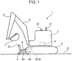
- FIG. 1 is a side view showing a hydraulic excavator 1 as an example of a work machine in which a blade control device according to an embodiment of the present invention is provided.
- the hydraulic excavator 1 includes a travelling device 2 (lower travelling body) capable of travelling on the ground G, a vehicle body 3 (upper slewing body) mounted on the travelling device 2, a work device mounted on the vehicle body 3, and a blade 4 mounted on the travelling device 2 or the vehicle body 3.
- the travelling device 2 and the vehicle body 3 constitute a machine body of the work machine.
- the vehicle body 3 has a slewing frame, an engine, a driver's room, and the like.
- the work device mounted on the vehicle body 3 includes a boom 5, an arm 6, and a bucket 7.
- the boom 5 has a base end portion supported at a front end of the slewing frame so as to go up and down, i.e., to be turnable around a horizontal axis, and a distal end portion on the opposite side.
- the arm 6 has a base end portion attached to the distal end portion of the boom 5 so as to be turnable around the horizontal axis, and a distal end portion on the opposite side.
- the bucket 7 is turnably attached to the distal end portion of the arm 6.
- the hydraulic excavator 1 has a boom cylinder, an arm cylinder, and a bucket cylinder provided for the boom 5, the arm 6, and the bucket 7, respectively.
- the boom cylinder is interposed between the vehicle body 3 and the boom 5 and extends and contracts so as to cause the boom 5 to conduct up-down operation.
- the arm cylinder is interposed between the boom 5 and the arm 6 and extends and contracts so as to cause the arm 6 to conduct turning operation.
- the bucket cylinder is interposed between the arm 6 and the bucket 7 and extends and contracts so as to cause the bucket 7 to conduct turning operation.
- the blade 4 mounted on the travelling device 2 or the vehicle body 3 is provided for conducting digging of the ground, land grading, transport of sediments, and the like. Specifically, the blade 4 is supported by a lift frame 4a, and the lift frame 4a is supported to be turnable around a horizontal axis 4b with respect to the travelling device 2. Accordingly, the blade 4 can be displaced in an up-down direction with respect to the travelling device 2.
- the hydraulic excavator 1 has a lift cylinder 8 provided for the blade 4.
- the lift cylinder 8 has a head chamber 8h and a rod chamber 8r (see FIG. 1 ), and extends to thereby cause the blade 4 to move in a down direction when a hydraulic oil is supplied to the head chamber 8h, as well as discharging the hydraulic oil in the rod chamber 8r, and also contracts to thereby cause the blade 4 to move in an up direction when the hydraulic oil is supplied to the rod chamber 8r, as well as discharging the hydraulic oil in the head chamber 8h.
- the hydraulic excavator 1 has a hydraulic circuit not shown.
- the hydraulic circuit includes the boom cylinder, the arm cylinder, the bucket cylinder, and the lift cylinder 8.
- the hydraulic circuit further includes a hydraulic pump 9 (see FIG. 1 ), a lift cylinder control proportional valve 41 (see FIG. 2 ), and a lift cylinder flow rate control valve not shown.
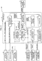
- FIG. 2 is a block diagram showing a main function of a blade control device 100.
- the blade control device 100 is provided for controlling raising and lowering operation of the blade 4.
- the blade control device 100 includes a controller 10 (mechatronic controller), a position information acquiring part, a blade load acquiring part 34, an automatic control switch 35, and a travelling lever 36 for manipulating the travelling device 2.
- the controller 10 which is configured with, for example, a microcomputer, controls operation of each element included in the hydraulic circuit.
- the position information acquiring part is configured to acquire position information about the hydraulic excavator 1.
- the position information acquiring part includes a vehicle body position acquiring part 31, a vehicle body angle acquiring part 32, and a blade angle acquiring part 33.
- the vehicle body position acquiring part 31 is configured to acquire a vehicle body position as a position of the machine body.
- the vehicle body position acquiring part 31 is configured with, for example, a receiver, such as a GNSS receiver (GNSS sensor), capable of receiving satellite data (positioning signal) from a satellite measurement system, such as GNSS (Global Navigation Satellite System), and receives GNSS data indicative of a vehicle body position as a position of the vehicle body 3 in a global coordinate system.
- the global coordinate system is a three-dimensional coordinate system using an origin point defined on the earth as a reference, which is a coordinate system indicating an absolute position defined by the satellite measurement system.
- the vehicle body angle acquiring part 32 is configured to acquire a vehicle body angle as an angle of the vehicle body 3.
- the vehicle body angle acquiring part 32 is configured with, for example, a vehicle body angle sensor which detects an angle of the vehicle body 3 in a global coordinate system.
- the vehicle body angle sensor may be configured with, for example, one or a plurality of receivers provided in the machine body and capable of receiving satellite data (positioning signal) from a satellite measurement system.
- the vehicle body angle is an angle of inclination of the vehicle body with respect to a horizontal surface.
- the blade angle acquiring part 33 is configured to acquire an angle of the blade 4.
- the blade angle acquiring part 33 is configured with, for example, a blade angle sensor which detects the angle of the blade 4 in a global coordinate system.
- the blade angle sensor may be configured with, for example, one or a plurality of receivers provided in the machine body and capable of receiving satellite data (positioning signal) from a satellite measurement system.
- a local coordinate system may be used in place of the global coordinate system. Both the global coordinate system and the local coordinate system may be used together. Examples of the local coordinate system include a three-dimensional coordinate system using the vehicle body position as a reference and a three-dimensional coordinate system using a specific position at a work site as a reference.
- the vehicle body angle sensor may be configured with, for example, an inertia measurement device, or may be configured with, for example, the inertia measurement device and the receiver capable of receiving the satellite data.
- the inertia measurement device may be configured to be capable of, for example, measuring an acceleration and an angular velocity of the vehicle body 3, and detecting an inclination (e.g., a pitch indicative of rotation with respect to an X-axis, a yaw indicative of rotation with respect to a Y-axis, and a roll indicative of rotation with respect to a Z-axis) of the vehicle body 3 on the basis of a measurement result.
- the blade angle sensor may be configured with, for example, a stroke sensor which detects a cylinder stroke of the blade cylinder 8, or may be configured with the stroke sensor and the receiver capable of receiving the satellite data.
- the vehicle body position acquiring part 31 and the vehicle body angle acquiring part 32 are attached to an upper portion of the vehicle body 3 and the blade angle acquiring part 33 is attached to an upper portion of the blade 4 as shown in FIG. 1
- the attachment positions are not limited to the specific example shown in FIG. 1 .
- Detection signals as electrical signals generated by these acquiring parts 31, 32, and 33 are input to the controller 10.
- the blade load acquiring part 34 is configured to acquire a blade load as a load applied on the blade 4 during digging work.
- the blade load corresponds to, for example, a pump pressure of the hydraulic pump 9 which drives the blade 4.
- the blade load acquiring part 34 is capable of detecting the blade load by detecting the pump pressure.
- the blade load acquiring part 34 includes a head pressure sensor 34H which detects a head pressure P1 as a pressure of a hydraulic oil in the head chamber 8h of the lift cylinder 8, and a rod pressure sensor 34R which detects a rod pressure P2 as a pressure of a hydraulic oil in the rod chamber 8r of the lift cylinder 8.
- the sensors 34H and 34R respectively convert their detected physical quantities into detection signals as electrical signals corresponding to the physical quantities and input the detection signals to the controller 10.
- the automatic control switch 35 is arranged in the driver's room and is electrically connected to the controller 10. Upon receiving manipulation for switching a control mode of the controller 10 from a manual manipulation mode to an automatic control mode, the automatic control switch 35 inputs a mode command signal related to the manipulation to the controller 10. The controller 10 switches setting of the control mode from the manual manipulation mode to the automatic control mode by the mode command signal input from the automatic control switch 35.
- the controller 10 is configured to automatically control operation of the lift cylinder 8 such that an execution surface to be executed by the blade 4 approaches a target design surface set in advance.
- a command value (command current) to the lift cylinder control proportional valve 41 for controlling operation of the lift cylinder 8 is output from the controller 10, a secondary pressure of the proportional valve 41 changes according to the command value and opening of the lift cylinder flow rate control valve changes according to the secondary pressure.
- a supply flow and a supply direction of a hydraulic oil to be supplied from the hydraulic pump 9 to the lift cylinder 8 via the lift cylinder flow rate control valve change to control an operation speed and a driving direction of the lift cylinder 8.
- the controller 10 has a target design surface setting part 11, a blade position calculating part 12, a storage part 13, a virtual design surface setting part 14, a blade operation control part 15, a load threshold value setting part 16, a blade control restricting part 20, and an estimated position calculating part 22 as a function for executing the automatic control.
- the target design surface setting part 11 sets a target design surface SD (see FIG. 7 ) which specifies a target shape of an object to be dug by the blade 4.
- the target design surface setting part 11 may store a design surface input by a target design surface input part provided in the driver's room and set the design surface as a target design surface.
- the target design surface setting part 11 may also store data of a design surface acquired via various kinds of storage media, a communication network, or the like and set the design surface as a target design surface.
- the target design surface setting part 11 inputs the set target design surface to the virtual design surface setting part 14.
- the target design surface SD is a surface which specifies a three-dimensional design topography as a target shape of the ground which is an object to be dug.
- the target design surface SD may be specified by external data such as BIM, CIM (Building/Construction Information Modeling, Management), etc., or may be set using a position of the work machine as a reference.
- the blade position calculating part 12 calculates a blade position as a position of the blade 4 in the global coordinate system on the basis of the position information acquired by the position information acquiring part.
- the blade position calculating part 12 calculates the blade position on the basis of the vehicle body position acquired by the vehicle body position acquiring part 31, the vehicle body angle acquired by the vehicle body angle acquiring part 32, and the angle of the blade 4 acquired by the blade angle acquiring part 33.
- the blade position is calculated from a sum of a vector from a reference point to the vehicle body position and a vector from the vehicle body position to the blade position.
- a blade position is thus calculated from a relative angle between the vehicle body angle and the angle of the blade 4 in the global coordinate system
- a blade position calculation method is not limited thereto.
- the blade position may be calculated on the basis of, for example, a length of the lift cylinder 8, or may be calculated on the basis of GNSS data received by a GNSS receiver (GNSS sensor) attached to the blade 4.
- GNSS sensor GNSS receiver
- the blade position is set at a blade edge position (a position of a lower edge of a distal end of the blade 4) as the distal end of the blade 4, the blade position may be set at other part of the blade 4.
- the storage part 13 stores a first load threshold value fl as a load threshold value which is a threshold value of the blade load f.
- the storage part 13 further stores a second load threshold value f2 which is a threshold value of the blade load f.
- the first load threshold value fl and the second load threshold value f2 will be described later.
- the storage part 13 stores an update condition set in advance.
- the update condition is used as a reference for determining whether or not the virtual design surface setting part 14 should update a virtual design surface to be described later.
- the update condition includes one or a plurality of conditions. The update condition will be detailed later.
- the virtual design surface setting part 14 sets a virtual design surface to be above the target design surface using the blade position when the update condition is satisfied as a reference, the virtual design surface being parallel to the vehicle body angle acquired by the vehicle body angle acquiring part 32.
- the virtual design surface setting part 14 sets a virtual design surface on the basis of a blade position calculated by the blade position calculating part 12, the first load threshold value f1 set by the load threshold value setting part 16, the blade load f acquired by the blade load acquiring part 34, a vehicle body position acquired by a GNSS receiver (the vehicle body position acquiring part 31), a vehicle body angle acquired by a vehicle body angle sensor (the vehicle body angle acquiring part 32), and a target design surface set by the target design surface setting part 11.
- a specific setting method will be described later.
- the load threshold value setting part 16 sets a load threshold value for use in calculation in the virtual design surface setting part 14 and the blade operation control part 15.
- the load threshold value setting part 16 sets the above-described first load threshold value f1 and second load threshold value f2.
- the second load threshold value f2 is set to be a value greater than the first load threshold value f1.
- the first load threshold value f1 is set to be a value corresponding to a proper blade load f with which the hydraulic excavator 1 can stably travel.
- the second load threshold value f2 is a value set to realize stable and efficient digging operation.
- the second load threshold value f2 is preferably set to be a value smaller than a blade load with which such a situation occurs. In other words, even when the blade load f reaches the second load threshold value f2, the second load threshold value f2 is preferably set to be a value with which the work machine can travel.
- These load threshold values f1 and f2 may be manually input to the controller 10 by a worker before the digging work or appropriately calculated by the controller 10 and stored during the digging work.
- the blade operation control part 15 calculates and outputs a command value to the lift cylinder control proportional valve 41 for controlling operation of the lift cylinder 8.
- the blade operation control part 15 calculates a temporary command current to be output to the lift cylinder control proportional valve 41 on the basis of an automatic control switch manipulation signal of the automatic control switch 35, a travelling lever manipulation signal of the travelling lever 36, the blade load f acquired by the blade load acquiring part 34, and the first load threshold value f1 and the second load threshold value f2 set by the load threshold value setting part 16. A specific calculation method will be described later.
- the blade control restricting part 20 calculates a command current to be output to the lift cylinder control proportional valve 41 on the basis of a virtual design surface calculated by the virtual design surface setting part 14 and the temporary command current calculated by the blade operation control part 15. A specific calculation method will be described later.
- the estimated position calculating part 22 calculates an estimated position of a present surface configuring a part of conditions included in the update condition. Specifically, the estimated position calculating part 22 calculates an estimated position of a part of the present surface which is the ground as the object to be dug, the part being associated with at least one of the blade 4 and the travelling device 2, on the basis of the position information acquired by the position information acquiring part. A specific calculation method will be described later.
- the controller 10 acquires an automatic control switch manipulation signal related to the automatic control switch 35 and a travelling lever manipulation signal related to the travelling lever 36 (Step S1).
- the controller 10 determines whether a condition is satisfied or not, the condition being that the automatic control switch manipulation signal indicates that the automatic control switch 35 is in an ON state and the travelling lever manipulation signal indicates that the travelling lever 36 has been manipulated (Step S2). In a case where the condition is not satisfied (NO in Step S2), the controller 10 resets a virtual design surface and finishes the processing.
- the load threshold value setting part 16 sets the first load threshold value f1 and the second load threshold value f2 (Step S3).
- the blade load acquiring part 34 acquires a blade load f applied to the blade 4 (Step S4).
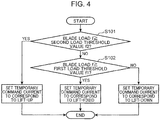
- FIG. 4 is a diagram showing a flow for calculation of the temporary command current by the blade operation control part 15 of the controller 10.
- the blade operation control part 15 determines whether a condition that the blade load f acquired by the blade load acquiring part 34 is equal to or greater than the second load threshold value f2 is satisfied or not (Step S101). In a case where the condition is satisfied (YES in Step S101), the blade operation control part 15 outputs a temporary command current corresponding to "lift-up" and finishes the processing.
- the temporary command current is input to the blade control restricting part 20. "Lift-up" corresponds to operation of raising the blade 4.
- Step S101 determines whether a condition is satisfied or not, the condition being that the blade load f is equal to or greater than the first load threshold value f1 (Step S102).
- Step S102 determines whether a condition is satisfied or not, the condition being that the blade load f is equal to or greater than the first load threshold value f1 (Step S102).
- the blade operation control part 15 outputs a temporary command current corresponding to "lift-fixed” and finishes the processing.
- the temporary command current is input to the blade control restricting part 20.
- "Lift fixed” corresponds to refraining from conducting the raising and lowering operation of the blade 4.
- Step S102 In a case where the condition of Step S102 is not satisfied (NO in Step S102), the blade operation control part 15 outputs a temporary command current corresponding to "lift-down" and finishes the processing.
- the temporary command current is input to the blade control restricting part 20.
- "Lift-down" corresponds to operation for lowering the blade 4.
- the flow shown in FIG. 4 represents processing intended to maintain a blade load f during the digging work within a range between the first load threshold value f1 and the second load threshold value f2.
- a load exceeding a digging capacity of the blade 4 is considered to be applied to the blade 4, and "lift-up "operation is conducted for lessening the blade load f.
- the blade load f is smaller than the first load threshold value f1
- a load applied to the blade 4 is considered excessively small for the digging capacity, so that "lift-down" operation is conducted for increasing a digging amount. Otherwise, processing of fixing a position of the, blade 4, i.e., processing of refraining from conducting the raising and lowering operation of the blade 4 is conducted.
- Step S6 the controller 10 determines whether a condition that the temporary command current output by the blade operation control part 15 corresponds to "lift-up" is satisfied or not (Step S6). In a case where the condition is satisfied (YES in Step S6), the blade control restricting part 20 conducts processing of Step S11. In a case where the condition is not satisfied (NO in Step S6), a series of processing of subsequent Steps S7 to S11 is conducted.
- the vehicle body position acquiring part 31 acquires the vehicle body position
- the vehicle body angle acquiring part 32 acquires the vehicle body angle
- the blade angle acquiring part 33 acquires the angle of the blade 4 (Step S7).
- the blade position calculating part 12 calculates the blade position on the basis of the vehicle body position, the vehicle body angle, and the angle of the blade 4 (Step S8).
- FIG. 5 is a diagram showing a flow for setting a virtual design surface by the virtual design surface setting part 14 of the controller 10.
- the virtual design surface setting part 14 determines whether a condition corresponding to non-setting of a virtual design surface is satisfied or not (Step S201). In the specific example shown in FIG. 5 , the virtual design surface setting part 14 determines in Step S201 whether the Step S201 is the first time in the automatic control or not.
- Step S201 is the first time in the automatic control
- a virtual design surface is not set, so that the determination whether the step is the first time in the automatic control or not can be determination whether a condition corresponding to non-setting of a virtual design surface is satisfied or not.
- the determination whether the condition corresponding to non-setting of a virtual design surface is satisfied or not may be also made on the basis of, for example, a flag (setting flag) indicative of setting or non-setting of a virtual setting surface.
- the virtual design surface setting part 14 determines whether a condition is satisfied or not, the condition being that a blade load f acquired last time by the blade load acquiring part 34 is equal to or greater than the first load threshold value f1 and a blade load f acquired this time by the blade load acquiring part 34 is smaller than the first load threshold value f1 (Step S202). In a case where the condition in question is satisfied (YES in Step S202), the virtual design surface setting part 14 newly sets a virtual design surface (update the virtual design surface) and finishes the processing.
- Step S203 determination is made whether a condition that the estimated position is below the virtual design surface is satisfied or not (Step S203). In a case of determining that the condition of Step S203 is satisfied (YES in Step S203), the virtual design surface setting part 14 newly sets a virtual design surface (update the virtual design surface) and finishes the processing. In a case where the condition of Step S203 is not satisfied (NO in Step S203), the virtual design surface setting part 14 refrains from updating the virtual design surface and finishes the processing.
- the flow shown in FIG. 5 represents processing intended to appropriately set a virtual design surface SV.
- processing of newly setting the virtual design surface SV processing of updating the virtual design surface SV is conducted in a case where at least one of the conditions is satisfied, the conditions including the condition that "the step is the first time in the automatic control" (Step S201), the condition that "a blade load f acquired last time is equal to or greater than the first load threshold value f1 and a blade load f acquired this time is smaller than the first load threshold value fl" (Step S202), and the condition that "the estimated position is below the currently set virtual design surface SV" (Step S203). Execution of the processing in question causes the virtual design surface SV to be set at an appropriate time to realize stable digging work with high work execution efficiency.
- FIG. 6 is a schematic side view for explaining the estimated position.
- An estimated position PB shown in FIG. 6 is calculated by the estimated position calculating part 22. Because of being arranged in a lower portion of the work machine, the blade 4 and the travelling device 2 are positioned at a height close to a height position of a present surface SP. Accordingly, at least one of the blade 4 and the travelling device 2 can be an index for determining a positional relationship between the virtual design surface SV and the present surface SP.
- the estimated position PB calculated by the estimated position calculating part 22 is obtained by calculating and estimating a part of the present surface SP, the part being associated with at least one of the blade 4 and the travelling device 2, by the estimated position calculating part 22 on the basis of the position information.
- the virtual design surface SV is updated to have an angle parallel to the vehicle body angle with the blade position as a reference, the state where the blade 4 floats above the present surface SP is eliminated.
- the estimated position PB is an intersection point between a line (line on the present surface SP in FIG. 6 ) parallel to a lower portion of the travelling device 2 in the work machine and a line L passing the blade position and extending perpendicularly from the virtual design surface SV as shown in FIG. 6 . Since the estimated position PB is an estimated height position of the present surface SP at the blade position, the estimated position can be a point of intersection, for example, at which the line parallel to the lower portion of the travelling device 2 in the work machine and the blade 4 intersect with each other.
- FIG. 7 is a schematic side view for explaining a method of setting the virtual design surface SV in the blade control device 100.
- the virtual design surface setting part 14 calculates a reference position, on a straight line passing the blade position and perpendicular to the target design surface SD, below the blade position by a reference distance ⁇ set in advance, and sets, as the virtual design surface SV, a plane passing the reference position and parallel to the vehicle body angle as shown in FIG. 7 .
- FIG. 8 is a diagram showing a flow for calculating the command current by the blade control restricting part 20 of the controller 10.
- the blade control restricting part 20 determines whether a condition is satisfied or not, the condition being that a blade position calculated by the blade position calculating part 12 is below the virtual design surface SV (Step S301).
- the blade control restricting part 20 sets the command current to correspond to "lift-up” and finishes the processing .
- "Lift-up" corresponds to operation of raising the blade 4.
- the blade control restricting part 20 sets the command current to be the same as the temporary command current input from the blade operation control part 15 and finishes the processing.
- the flow shown in FIG. 8 is processing intended to maintain the blade position above the virtual design surface SV.
- processing is conducted for overwriting the command current with "lift-up” such that the blade position does not fall below the virtual design surface SV. This prevents generation of waviness on an execution surface SC.
- Step S11 shown in FIG. 3 the blade control restricting part 20 outputs the command current to the lift cylinder control proportional valve 41. Specifically, in a case where a condition that the temporary command current output by the blade operation control part 15 corresponds to "lift-up" is satisfied (YES in Step S6), the blade control restricting part 20 outputs the same command current as the temporary command current to the proportional valve 41. Additionally, in a case of NO in the Step S6, the blade control restricting part 20 outputs a command current calculated in Step S10 to the proportional valve 41. When the processing of Step S11 is finished, the controller 10 again conducts the processing of Step S1.
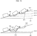
- FIG. 15 is a schematic side view showing one example of a design surface SD (target design surface), present surfaces SP1 and SP2, virtual design surfaces SV11, SV12, SV13, and SV21, and execution surfaces SC1 and SC2 when a work machine provided with the blade control device according to the reference example conducts digging work while ascending a slope along the present surfaces SP1 and SP2.
- a design surface SD target design surface
- present surfaces SP1 and SP2 virtual design surfaces SV11, SV12, SV13, and SV21
- execution surfaces SC1 and SC2 execution surfaces
- the updated virtual design surface SV12 is set to be parallel to the horizontal design surface SD and is set to be above the virtual design surface SV11 set last time. While first digging work is thus conducted in which the work machine ascends the slope along the present surface SP1 to dig the whole of the present surface SP1, the plurality of horizontal virtual design surfaces SV11, SV12, and SV13 is set in a stepped manner as shown in the upper view of FIG. 15 , and the execution surface SC1 executed by the first digging work is also formed to be stepped. Thus formed stepped first execution surface SC1 will make the present surface SP2 as an object to be dug in second digging work to be conducted next (see a lower view of FIG. 15 ). Accordingly, as shown in the lower view of FIG.
- FIG. 16 is a schematic side view showing one example of a design surface SD, a present surface SP, a virtual design surface SV11, and an execution surface SC when the work machine provided with the blade control device according to the reference example conducts the digging work while descending a slope along the present surface SP.
- the virtual design surface SV21 in the lower view of FIG. 15 is a virtual design surface set for the second digging work and is a virtual design surface parallel to the target design surface SD.
- the virtual design surface SV set by the virtual design surface setting part 14 is not parallel to the target design surface SD but parallel to the vehicle body angle, waviness of the execution surface SC can be suppressed and controllability of a posture of the work machine, ride comfort of a worker, and work execution efficiency during the digging work can be also suppressed.
- Specifics are as follows.
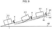
- FIG. 9 is a schematic side view showing one example of a design surface SD (target design surface), a present surface SP, a virtual design surface SV, and an execution surface SC when the work machine provided with the blade control device 100 according to the present embodiment conducts the digging work while ascending a slope along the present surface SP
- FIG. 10 is a schematic side view showing one example in which the work machine conducts the digging work while descending a slope along the present surface SP
- FIG. 11 is a schematic side view showing one example in which the work machine conducts the digging work while ascending and descending a slope along a present surface SP.
- the virtual design surface SV since in the present embodiment, the virtual design surface SV is set in parallel to the vehicle body angle of the work machine ascending the slope along the present surface SP of the up-grade, the virtual design surface SV will not be set in a stepped manner as in the reference example shown in the upper view of FIG. 15 , resulting in suppressing also the execution surface SC from being formed in a stepped manner. This suppresses fluctuation of the vehicle body in a pitch direction at the time of again digging the execution surface SC, thereby obtaining an effect of eliminating deterioration in controllability of a posture of the work machine and deterioration in ride comfort of a worker.
- setting the virtual design surface SV to be parallel to the vehicle body angle of the work machine descending the slope along the present surface SP of the down-grade as shown in FIG. 10 enables resetting of the virtual design surface SV (the virtual design surface SV of the down-grade) parallel to the vehicle body angle of the work machine having a posture along the present surface SP of the down-grade. This enables, even if the virtual design surface SV enters a state of being above the present surface SP, elimination of the state to thereby suppress reduction in work execution efficiency.
- the blade control device 100 is effective also in a case where the present surface has a relatively large uneven spot as shown in FIG. 11 .
- the virtual design surface SV can have various angles according the vehicle body angle. As shown in FIG. 11 , this suppresses a plurality of virtual design surfaces SV1, SV2, SV3, and SV4 from being formed in a horizontal stepped manner as in the reference example, the virtual design surfaces being set during the first digging work in which the work machine ascends the slope along the present surface SP to dig the whole of the present surface.
- each of the plurality of virtual design surfaces SV1, SV2, SV3, and SV4 formed in the first digging work is set in parallel to the vehicle body angle of the work machine having a posture along the present surface SP of the up-grade, the plurality of virtual design surfaces SV is liable to follow the up-grade of the present surface SP.
- the work machine when in the second digging work in which the execution surface SC of the first digging work is used as a present surface, the work machine ascends the slope along the present surface while digging the present surface, fluctuation of the vehicle body of the work machine in its pitch direction can be suppressed. This suppresses deterioration in controllability of controlling a posture of the work machine and deterioration in ride comfort of a worker. Additionally, waviness of such an execution surface dug by the blade 4 as described above will be suppressed, the blade having raising and lowering operation restricted on the basis of the virtual design surfaces SV1, SV2, SV3, and SV4.
- FIG. 12 is a block diagram showing a main function of a blade control device 100 according to a modification example of the present embodiment.
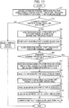
- FIG. 13 is a flowchart showing one example of control operation to be executed by a controller 10 included in the blade control device 100 according to the modification example.
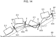
- FIG. 14 is a schematic side view showing one example of a design surface SD, a present surface SP, a virtual design surface SV, and an execution surface SC when a work machine provided with the blade control device 100 according to the modification example conducts digging work while ascending and descending a slope along the present surface SP.
- the blade control device 100 according to the modification example shown in FIG. 12 is different from the blade control device 100 shown in FIG. 2 in that the controller 10 further includes a vehicle body average angle calculating part 21, and has the remaining configuration being the same as that of the blade control device 100 shown in FIG. 2 .
- the flowchart shown in FIG. 13 is different from the flowchart shown in FIG. 3 in that between the processing of Step S8 and the processing of Step S9, processing of Step S12 is added, and includes the remaining processing being the same as that of the flowchart shown in FIG. 3 .
- the vehicle body average angle calculating part 21 calculates an average value of vehicle body angles acquired by the position information acquiring part.
- the virtual design surface setting part 14 is configured to use the average value of the vehicle body angles as the vehicle body angle to be a reference for setting the virtual design surface SV.
- the virtual design surfaces SV1, SV2, SV3, and SV4 are set to be parallel to an average value of the vehicle body angles as shown in FIG. 14 , update time of the virtual design surfaces SV2, SV3, and SV4 is less liable to depend on a local uneven spot and the like. This enables reduction in an amount of change in angles of the virtual design surfaces SV2, SV3, and SV4 at the time of update to thereby enable more stable digging work.
- an average value calculation method is not limited to the above-described method.
- the virtual design surface setting part 14 calculates a reference position, on a straight line passing the blade position and perpendicular to the target design surface SD, below the blade position by a reference distance ⁇ set in advance, and sets, as the virtual design surface SV, a plane passing the reference position and parallel to the average value of the vehicle body angles.
- a plane parallel to the average value of the vehicle body angles in continuous time is set as a virtual design surface, and this arrangement allows the virtual design surface SV to follow an average angle of the vehicle body, i.e., follow an average gradient of the present surface even in a case where the present surface has an uneven spot. This enables reduction in an amount of change in an angle of the virtual design surface at the time of update to thereby enable more stable digging work.
- the virtual design surface SV is set to be parallel to the average value of the vehicle body angles in continuous time, an amount of change in an angle of the virtual design surface at the time of update can be reduced, resulting in having an effect of eliminating deterioration of work execution efficiency and an effect of enabling more stable digging as compared with the embodiment shown in FIG. 11 .
- the present invention is not limited to the above-described embodiments.
- the present invention may include the following modes, for example.
- a work machine to which the blade control device according to the present invention is applied is not limited to a hydraulic excavator.
- the present invention is widely applicable to other work machine provided with a blade, such as a wheel loader, a bulldozer, and the like.
- a blade control device capable of effectively suppressing waviness of an execution surface.
- the blade control device is a device which is provided in a work machine including a machine body having a travelling device and a vehicle body supported by the travelling device and a blade attached to the machine body so as to be raised and lowered and which controls raising and lowering operation of the blade.
- the blade control device includes a target design surface setting part which sets a target design surface that specifies a target shape of an object to be dug by the blade; a position information acquiring part which acquires position information related to the work machine; a blade position calculating part which calculates a blade position as a position of the blade on the basis of the position information acquired by the position information acquiring part; a virtual design surface setting part which sets a virtual design surface above the target design surface; and a blade operation control part which controls the raising and lowering operation of the blade.
- the virtual design surface setting part sets the virtual design surface, using the blade position when the update condition is satisfied as a reference, at an angle equivalent to a vehicle body angle as an angle of inclination of the vehicle body with respect to a horizontal surface, the angle of inclination being obtained on the basis of the position information.
- the blade operation control part restricts the raising and lowering operation of the blade such that the blade conducts the raising and lowering operation above the virtual design surface.
- the virtual design surface is set not to be parallel to the target design surface but to be parallel to the vehicle body angle. Accordingly, in a case, for example, where a present surface (the ground) has an up-grade or a down-grade with respect to a horizontal target design surface and a work machine conducts digging work while ascending a slope along the present surface or descending the slope along the present surface, the virtual design surface is liable to follow the up-grade or the down-grade. This suppresses fluctuation of a distance between the present surface and the virtual design surface, thereby suppressing fluctuation of a blade load as well. When fluctuation of a blade load is suppressed, the raising and lowering operation of the blade will be suppressed, so that waviness of an execution surface will be suppressed.
- the blade control device further includes an estimated position calculating part which calculates an estimated position of a part of a present surface which is the ground as the object to be dug, the part being associated with at least one of the blade and the travelling device, on the basis of the position information acquired by the position information acquiring part, in which the update condition includes a condition that the estimated position is below the virtual design surface.
- an estimated position calculating part which calculates an estimated position of a part of a present surface which is the ground as the object to be dug, the part being associated with at least one of the blade and the travelling device, on the basis of the position information acquired by the position information acquiring part, in which the update condition includes a condition that the estimated position is below the virtual design surface.
- a present surface the ground
- a vehicle body angle of the work machine relatively greatly fluctuates, and a virtual design surface set in parallel to the vehicle body angle is liable to be set in a relatively large angle range.
- the virtual design surface may be temporarily positioned above a part, of the present surface, corresponding to the blade, or a part, of the present surface, corresponding to the travelling device.
- the blade restricted to be above the virtual design surface enters a state of floating above the present surface.
- the blade and the travelling device are positioned at a height close to a height position of a present surface. Accordingly, at least one of the blade and the travelling device can be an index for determining a positional relationship between the virtual design surface and the present surface.
- the estimated position calculated by the estimated position calculating part is obtained by calculating and estimating a part of the present surface, the part being associated with at least one of the blade and the travelling device, by the estimated position calculating part on the basis of the position information. Accordingly, when the condition that the estimated position is below the virtual design surface is satisfied, a possibility that the blade enters a state of floating above the present surface will be increased. Since in the present mode, when the update condition including this condition is satisfied, the virtual design surface is updated to have an angle parallel to the vehicle body angle with the blade position as a reference, the state where the blade floats above the present surface is eliminated.
- the update condition preferably includes a condition corresponding to non-setting of the virtual design surface.
- a virtual design surface is not set, when the update condition including the condition in question is satisfied, a virtual design surface parallel to a vehicle body angle is set. This enables digging work to have high work execution efficiency from an initial stage of the automatic control of the blade.
- the blade control device further includes a blade load acquiring part which acquires a blade load as a load applied to the blade; and a storage part which stores a load threshold value as a threshold value of the blade load, in which the update condition includes a condition that the blade load changes from a value equal to or greater than the load threshold value to a value smaller than the load threshold value.
- Time when the blade load changes from a value equal to or greater than the load threshold value to a value smaller than the load threshold value corresponds to time when operation of reducing a load applied to the blade is conducted.
- Such a state of a reduced blade load is a more desirable state as compared with a state of an increased blade load in view of stability of the digging work. Accordingly, stability of the digging work is improved by setting, when the update condition including the condition in question is satisfied, a virtual design surface, and conducting the digging work in which the raising and lowering operation of the blade is restricted on the basis of the virtual design surface.
- the blade control device is preferably configured to further include a vehicle body average angle calculating part which calculates an average value of vehicle body angles acquired by the position information acquiring part, in which the virtual design surface setting part uses the average value of the vehicle body angles as the vehicle body angle to be a reference for setting the virtual design surface. Since in this mode, even in a case where a present surface as an object to be dug has a relatively large uneven spot, a virtual design surface is set to be parallel to the average value of the vehicle body angles, update time of the virtual design surface is less liable to depend on a local uneven spot and the like. This enables reduction in an amount of change in an angle of the virtual design surface at the time of update to thereby enable more stable digging work.
Landscapes
- Engineering & Computer Science (AREA)
- Mining & Mineral Resources (AREA)
- Civil Engineering (AREA)
- General Engineering & Computer Science (AREA)
- Structural Engineering (AREA)
- Mechanical Engineering (AREA)
- Operation Control Of Excavators (AREA)
Abstract
Description
- The present invention relates to a blade control device provided in a work machine including a blade.
- Conventionally, a work machine including a blade for use in digging of the ground, land grading, transport of sediments, and the like has been used widely. Although there is proposed a method of automatically controlling raising and lowering operation of a blade such that a blade load applied to the blade becomes substantially constant in such a work machine, the method has a problem of waviness of an execution surface generated due to raising and lowering operation of a blade.
- Patent Literature 1 discloses a blade control device intended to suppress waviness of an execution surface. In the blade control device of Patent Literature 1, while restricting fluctuation of a blade to above a virtual design surface set in parallel to a design surface and closer to the blade than to the design surface, a blade operation control part lowers the blade in a case where a blade load is smaller than a first set load value, and raises the blade in a case where the blade load is greater than a second set load value which is greater than the first set load value. A virtual design surface setting part resets the virtual design surface parallel to the design surface when the blade load is lowered from a value equal to or greater than the first set load value to a value smaller than the first set load value. In the blade control device of Patent Literature 1, the virtual design surface setting part also sets a virtual design surface at a position more away from the design surface than a virtual design surface set last time. In other words, a virtual design surface will be upwardly moved more away from the design surface every time the virtual design surface is updated.
- However, since in such a blade control device recited in Patent Literature 1 as described above, in a case, for example, where a present surface (the ground) has an up-grade or a down-grade with respect to a horizontal design surface and a work machine conducts digging work while ascending a slope along the present surface or descending the slope along the present surface, a blade load is greatly affected by a gradient of the present surface, raising and lowering operation of the blade is increased, so that an effect of suppressing waviness of an execution surface cannot be always considered sufficient.
- Patent Literature 1:
JP 5285805 B - An object of the present invention is to provide a blade control device which is provided in a work machine including a blade and controls raising and lowering operation of the blade, the blade control device being capable of effectively suppressing waviness of an execution surface.
- A blade control device of the present invention is a device which is provided in a work machine including a machine body having a travelling device and a vehicle body supported by the travelling device and a blade attached to the machine body so as to be raised and lowered and which controls raising and lowering operation of the blade. The blade control device includes a target design surface setting part which sets a target design surface that specifies a target shape of an object to be dug by the blade; a position information acquiring part which acquires position information related to the work machine; a blade position calculating part which calculates a blade position as a position of the blade on the basis of the position information acquired by the position information acquiring part; a virtual design surface setting part which sets a virtual design surface above the target design surface; and a blade operation control part which controls the raising and lowering operation of the blade. In a case where an update condition set in advance is satisfied, the virtual design surface setting part sets the virtual design surface, using the blade position when the update condition is satisfied as a reference, at an angle equivalent to a vehicle body angle as an angle of inclination of the vehicle body with respect to a horizontal surface, the angle of inclination being obtained on the basis of the position information. The blade operation control part restricts the raising and lowering operation of the blade such that the blade conducts the raising and lowering operation above the virtual design surface.
-
-
FIG. 1 is a side view showing a hydraulic excavator as an example of a work machine in which a blade control device according to an embodiment of the present invention is provided. -
FIG. 2 is a block diagram showing a main function of the blade control device according to the embodiment. -
FIG. 3 is a flowchart showing one example of control operation to be executed by a controller included in the blade control device. -
FIG. 4 is a flowchart showing one example of control operation to be executed by a blade operation control part out of the control operation to be executed by the controller. -
FIG. 5 is a flowchart showing one example of control operation to be executed by a virtual design surface setting part out of the control operation to be executed by the controller. -
FIG. 6 is a schematic side view for explaining an estimated position in the blade control device. -
FIG. 7 is a schematic side view for explaining setting of a virtual design surface in the blade control device. -
FIG. 8 is a flowchart showing one example of control operation to be executed by a blade control restricting part out of the control operation to be executed by the controller. -
FIG. 9 is a schematic side view showing one example of a design surface, a present surface, a virtual design surface, and an execution surface when the work machine provided with the blade control device conducts digging work while ascending a slope along the present surface. -
FIG. 10 is a schematic side view showing one example of a design surface, a present surface, a virtual design surface, and an execution surface when the work machine provided with the blade control device conducts the digging work while descending a slope along the present surface. -
FIG. 11 is a schematic side view showing one example of a design surface, a present surface, a virtual design surface, and an execution surface when the work machine provided with the blade control device conducts the digging work while ascending and descending a slope along the present surface. -
FIG. 12 is a block diagram showing a main function of a blade control device according to a modification example of the embodiment. -
FIG. 13 is a flowchart showing one example of control operation to be executed by a controller included in the blade control device according to the modification example. -
FIG. 14 is a schematic side view showing one example of a design surface, a present surface, a virtual design surface, and an execution surface when a work machine provided with the blade control device according to the modification example conducts digging work while ascending and descending a slope along a present surface. -
FIG. 15 is a schematic side view showing one example of a design surface, a present surface, a virtual design surface, and an execution surface when a work machine provided with a blade control device according to a reference example conducts digging work while ascending a slope along a present surface. -
FIG. 16 is a schematic side view showing one example of a design surface, a present surface, a virtual design surface, and an execution surface when the work machine provided with the blade control device according to the reference example conducts the digging work while descending a slope along the present surface. - A preferred embodiment of the present invention will be described with reference to the drawings.
-
FIG. 1 is a side view showing a hydraulic excavator 1 as an example of a work machine in which a blade control device according to an embodiment of the present invention is provided. - The hydraulic excavator 1 includes a travelling device 2 (lower travelling body) capable of travelling on the ground G, a vehicle body 3 (upper slewing body) mounted on the
travelling device 2, a work device mounted on thevehicle body 3, and ablade 4 mounted on thetravelling device 2 or thevehicle body 3. Thetravelling device 2 and thevehicle body 3 constitute a machine body of the work machine. Thevehicle body 3 has a slewing frame, an engine, a driver's room, and the like. - The work device mounted on the
vehicle body 3 includes aboom 5, an arm 6, and abucket 7. Theboom 5 has a base end portion supported at a front end of the slewing frame so as to go up and down, i.e., to be turnable around a horizontal axis, and a distal end portion on the opposite side. The arm 6 has a base end portion attached to the distal end portion of theboom 5 so as to be turnable around the horizontal axis, and a distal end portion on the opposite side. Thebucket 7 is turnably attached to the distal end portion of the arm 6. - The hydraulic excavator 1 has a boom cylinder, an arm cylinder, and a bucket cylinder provided for the
boom 5, the arm 6, and thebucket 7, respectively. The boom cylinder is interposed between thevehicle body 3 and theboom 5 and extends and contracts so as to cause theboom 5 to conduct up-down operation. The arm cylinder is interposed between theboom 5 and the arm 6 and extends and contracts so as to cause the arm 6 to conduct turning operation. The bucket cylinder is interposed between the arm 6 and thebucket 7 and extends and contracts so as to cause thebucket 7 to conduct turning operation. - The
blade 4 mounted on thetravelling device 2 or thevehicle body 3 is provided for conducting digging of the ground, land grading, transport of sediments, and the like. Specifically, theblade 4 is supported by alift frame 4a, and thelift frame 4a is supported to be turnable around ahorizontal axis 4b with respect to thetravelling device 2. Accordingly, theblade 4 can be displaced in an up-down direction with respect to thetravelling device 2. - The hydraulic excavator 1 has a lift cylinder 8 provided for the
blade 4. The lift cylinder 8 has ahead chamber 8h and arod chamber 8r (seeFIG. 1 ), and extends to thereby cause theblade 4 to move in a down direction when a hydraulic oil is supplied to thehead chamber 8h, as well as discharging the hydraulic oil in therod chamber 8r, and also contracts to thereby cause theblade 4 to move in an up direction when the hydraulic oil is supplied to therod chamber 8r, as well as discharging the hydraulic oil in thehead chamber 8h. - The hydraulic excavator 1 has a hydraulic circuit not shown. The hydraulic circuit includes the boom cylinder, the arm cylinder, the bucket cylinder, and the lift cylinder 8. The hydraulic circuit further includes a hydraulic pump 9 (see
FIG. 1 ), a lift cylinder control proportional valve 41 (seeFIG. 2 ), and a lift cylinder flow rate control valve not shown. -
FIG. 2 is a block diagram showing a main function of ablade control device 100. Theblade control device 100 is provided for controlling raising and lowering operation of theblade 4. Theblade control device 100 includes a controller 10 (mechatronic controller), a position information acquiring part, a bladeload acquiring part 34, anautomatic control switch 35, and atravelling lever 36 for manipulating thetravelling device 2. Thecontroller 10, which is configured with, for example, a microcomputer, controls operation of each element included in the hydraulic circuit. - The position information acquiring part is configured to acquire position information about the hydraulic excavator 1. Specifically, in the present embodiment, the position information acquiring part includes a vehicle body
position acquiring part 31, a vehicle bodyangle acquiring part 32, and a bladeangle acquiring part 33. The vehicle bodyposition acquiring part 31 is configured to acquire a vehicle body position as a position of the machine body. The vehicle bodyposition acquiring part 31 is configured with, for example, a receiver, such as a GNSS receiver (GNSS sensor), capable of receiving satellite data (positioning signal) from a satellite measurement system, such as GNSS (Global Navigation Satellite System), and receives GNSS data indicative of a vehicle body position as a position of thevehicle body 3 in a global coordinate system. The global coordinate system is a three-dimensional coordinate system using an origin point defined on the earth as a reference, which is a coordinate system indicating an absolute position defined by the satellite measurement system. - The vehicle body
angle acquiring part 32 is configured to acquire a vehicle body angle as an angle of thevehicle body 3. The vehicle bodyangle acquiring part 32 is configured with, for example, a vehicle body angle sensor which detects an angle of thevehicle body 3 in a global coordinate system. Specifically, the vehicle body angle sensor may be configured with, for example, one or a plurality of receivers provided in the machine body and capable of receiving satellite data (positioning signal) from a satellite measurement system. The vehicle body angle is an angle of inclination of the vehicle body with respect to a horizontal surface. - The blade
angle acquiring part 33 is configured to acquire an angle of theblade 4. The bladeangle acquiring part 33 is configured with, for example, a blade angle sensor which detects the angle of theblade 4 in a global coordinate system. Specifically, the blade angle sensor may be configured with, for example, one or a plurality of receivers provided in the machine body and capable of receiving satellite data (positioning signal) from a satellite measurement system. - A local coordinate system may be used in place of the global coordinate system. Both the global coordinate system and the local coordinate system may be used together. Examples of the local coordinate system include a three-dimensional coordinate system using the vehicle body position as a reference and a three-dimensional coordinate system using a specific position at a work site as a reference. In the above case, the vehicle body angle sensor may be configured with, for example, an inertia measurement device, or may be configured with, for example, the inertia measurement device and the receiver capable of receiving the satellite data. The inertia measurement device may be configured to be capable of, for example, measuring an acceleration and an angular velocity of the
vehicle body 3, and detecting an inclination (e.g., a pitch indicative of rotation with respect to an X-axis, a yaw indicative of rotation with respect to a Y-axis, and a roll indicative of rotation with respect to a Z-axis) of thevehicle body 3 on the basis of a measurement result. The blade angle sensor may be configured with, for example, a stroke sensor which detects a cylinder stroke of the blade cylinder 8, or may be configured with the stroke sensor and the receiver capable of receiving the satellite data. - Although, in the present embodiment, the vehicle body
position acquiring part 31 and the vehicle bodyangle acquiring part 32 are attached to an upper portion of thevehicle body 3 and the bladeangle acquiring part 33 is attached to an upper portion of theblade 4 as shown inFIG. 1 , the attachment positions are not limited to the specific example shown inFIG. 1 . Detection signals as electrical signals generated by these acquiringparts controller 10. - In the present embodiment, the blade
load acquiring part 34 is configured to acquire a blade load as a load applied on theblade 4 during digging work. The blade load corresponds to, for example, a pump pressure of thehydraulic pump 9 which drives theblade 4. Accordingly, the bladeload acquiring part 34 is capable of detecting the blade load by detecting the pump pressure. In the present embodiment, the bladeload acquiring part 34 includes ahead pressure sensor 34H which detects a head pressure P1 as a pressure of a hydraulic oil in thehead chamber 8h of the lift cylinder 8, and arod pressure sensor 34R which detects a rod pressure P2 as a pressure of a hydraulic oil in therod chamber 8r of the lift cylinder 8. Thesensors controller 10. - The
automatic control switch 35 is arranged in the driver's room and is electrically connected to thecontroller 10. Upon receiving manipulation for switching a control mode of thecontroller 10 from a manual manipulation mode to an automatic control mode, theautomatic control switch 35 inputs a mode command signal related to the manipulation to thecontroller 10. Thecontroller 10 switches setting of the control mode from the manual manipulation mode to the automatic control mode by the mode command signal input from theautomatic control switch 35. - In the automatic control mode, the
controller 10 is configured to automatically control operation of the lift cylinder 8 such that an execution surface to be executed by theblade 4 approaches a target design surface set in advance. When a command value (command current) to the lift cylinder controlproportional valve 41 for controlling operation of the lift cylinder 8 is output from thecontroller 10, a secondary pressure of theproportional valve 41 changes according to the command value and opening of the lift cylinder flow rate control valve changes according to the secondary pressure. As a result, a supply flow and a supply direction of a hydraulic oil to be supplied from thehydraulic pump 9 to the lift cylinder 8 via the lift cylinder flow rate control valve change to control an operation speed and a driving direction of the lift cylinder 8. On the other hand, in the manual manipulation mode, when a worker manipulates the travellinglever 36, a manipulation signal of the manipulation is input to thecontroller 10, and the command value to the lift cylinder controlproportional valve 41 or a command value to the lift cylinder flow rate control valve is output from thecontroller 10 according an amount of manipulation of a manipulation lever not shown for manipulating raising and lowering of theblade 4. - The
controller 10 has a target designsurface setting part 11, a bladeposition calculating part 12, astorage part 13, a virtual designsurface setting part 14, a bladeoperation control part 15, a load thresholdvalue setting part 16, a bladecontrol restricting part 20, and an estimatedposition calculating part 22 as a function for executing the automatic control. - The target design
surface setting part 11 sets a target design surface SD (seeFIG. 7 ) which specifies a target shape of an object to be dug by theblade 4. The target designsurface setting part 11 may store a design surface input by a target design surface input part provided in the driver's room and set the design surface as a target design surface. The target designsurface setting part 11 may also store data of a design surface acquired via various kinds of storage media, a communication network, or the like and set the design surface as a target design surface. The target designsurface setting part 11 inputs the set target design surface to the virtual designsurface setting part 14. The target design surface SD is a surface which specifies a three-dimensional design topography as a target shape of the ground which is an object to be dug. The target design surface SD may be specified by external data such as BIM, CIM (Building/Construction Information Modeling, Management), etc., or may be set using a position of the work machine as a reference. - The blade
position calculating part 12 calculates a blade position as a position of theblade 4 in the global coordinate system on the basis of the position information acquired by the position information acquiring part. In the present embodiment, the bladeposition calculating part 12 calculates the blade position on the basis of the vehicle body position acquired by the vehicle bodyposition acquiring part 31, the vehicle body angle acquired by the vehicle bodyangle acquiring part 32, and the angle of theblade 4 acquired by the bladeangle acquiring part 33. In other words, the blade position is calculated from a sum of a vector from a reference point to the vehicle body position and a vector from the vehicle body position to the blade position. Although in the present embodiment, a blade position is thus calculated from a relative angle between the vehicle body angle and the angle of theblade 4 in the global coordinate system, a blade position calculation method is not limited thereto. The blade position may be calculated on the basis of, for example, a length of the lift cylinder 8, or may be calculated on the basis of GNSS data received by a GNSS receiver (GNSS sensor) attached to theblade 4. - Although in the present embodiment, the blade position is set at a blade edge position (a position of a lower edge of a distal end of the blade 4) as the distal end of the
blade 4, the blade position may be set at other part of theblade 4. - The
storage part 13 stores a first load threshold value fl as a load threshold value which is a threshold value of the blade load f. In the present embodiment, thestorage part 13 further stores a second load threshold value f2 which is a threshold value of the blade load f. The first load threshold value fl and the second load threshold value f2 will be described later. - Additionally, the
storage part 13 stores an update condition set in advance. The update condition is used as a reference for determining whether or not the virtual designsurface setting part 14 should update a virtual design surface to be described later. The update condition includes one or a plurality of conditions. The update condition will be detailed later. - In a case where the update condition is satisfied, the virtual design
surface setting part 14 sets a virtual design surface to be above the target design surface using the blade position when the update condition is satisfied as a reference, the virtual design surface being parallel to the vehicle body angle acquired by the vehicle bodyangle acquiring part 32. The virtual designsurface setting part 14 sets a virtual design surface on the basis of a blade position calculated by the bladeposition calculating part 12, the first load threshold value f1 set by the load thresholdvalue setting part 16, the blade load f acquired by the bladeload acquiring part 34, a vehicle body position acquired by a GNSS receiver (the vehicle body position acquiring part 31), a vehicle body angle acquired by a vehicle body angle sensor (the vehicle body angle acquiring part 32), and a target design surface set by the target designsurface setting part 11. A specific setting method will be described later. - The load threshold
value setting part 16 sets a load threshold value for use in calculation in the virtual designsurface setting part 14 and the bladeoperation control part 15. In the present embodiment, the load thresholdvalue setting part 16 sets the above-described first load threshold value f1 and second load threshold value f2. The second load threshold value f2 is set to be a value greater than the first load threshold value f1. The first load threshold value f1 is set to be a value corresponding to a proper blade load f with which the hydraulic excavator 1 can stably travel. The second load threshold value f2 is a value set to realize stable and efficient digging operation. Because of being a value set for preventing occurrence of such a situation that the blade load f becomes excessively large to cause a stuck state, the second load threshold value f2 is preferably set to be a value smaller than a blade load with which such a situation occurs. In other words, even when the blade load f reaches the second load threshold value f2, the second load threshold value f2 is preferably set to be a value with which the work machine can travel. These load threshold values f1 and f2 may be manually input to thecontroller 10 by a worker before the digging work or appropriately calculated by thecontroller 10 and stored during the digging work. - The blade
operation control part 15 calculates and outputs a command value to the lift cylinder controlproportional valve 41 for controlling operation of the lift cylinder 8. The bladeoperation control part 15 calculates a temporary command current to be output to the lift cylinder controlproportional valve 41 on the basis of an automatic control switch manipulation signal of theautomatic control switch 35, a travelling lever manipulation signal of the travellinglever 36, the blade load f acquired by the bladeload acquiring part 34, and the first load threshold value f1 and the second load threshold value f2 set by the load thresholdvalue setting part 16. A specific calculation method will be described later. - The blade
control restricting part 20 calculates a command current to be output to the lift cylinder controlproportional valve 41 on the basis of a virtual design surface calculated by the virtual designsurface setting part 14 and the temporary command current calculated by the bladeoperation control part 15. A specific calculation method will be described later. - The estimated
position calculating part 22 calculates an estimated position of a present surface configuring a part of conditions included in the update condition. Specifically, the estimatedposition calculating part 22 calculates an estimated position of a part of the present surface which is the ground as the object to be dug, the part being associated with at least one of theblade 4 and the travellingdevice 2, on the basis of the position information acquired by the position information acquiring part. A specific calculation method will be described later. - Next, description will be made of control operation conducted by the
controller 10 for the driving of theblade 4 in the automatic control mode with reference to the flowchart ofFIG. 3 . - The
controller 10 acquires an automatic control switch manipulation signal related to theautomatic control switch 35 and a travelling lever manipulation signal related to the travelling lever 36 (Step S1). - Next, the
controller 10 determines whether a condition is satisfied or not, the condition being that the automatic control switch manipulation signal indicates that theautomatic control switch 35 is in an ON state and the travelling lever manipulation signal indicates that the travellinglever 36 has been manipulated (Step S2). In a case where the condition is not satisfied (NO in Step S2), thecontroller 10 resets a virtual design surface and finishes the processing. - In a case where the condition is satisfied (YES in Step S2), the load threshold
value setting part 16 sets the first load threshold value f1 and the second load threshold value f2 (Step S3). - Next, the blade
load acquiring part 34 acquires a blade load f applied to the blade 4 (Step S4). - Next, the blade
operation control part 15 calculates the temporary command current (Step S5).FIG. 4 is a diagram showing a flow for calculation of the temporary command current by the bladeoperation control part 15 of thecontroller 10. As shown inFIG. 4 , the bladeoperation control part 15 determines whether a condition that the blade load f acquired by the bladeload acquiring part 34 is equal to or greater than the second load threshold value f2 is satisfied or not (Step S101). In a case where the condition is satisfied (YES in Step S101), the bladeoperation control part 15 outputs a temporary command current corresponding to "lift-up" and finishes the processing. The temporary command current is input to the bladecontrol restricting part 20. "Lift-up" corresponds to operation of raising theblade 4. - In a case where the condition of Step S101 is not satisfied (NO in Step S101), the blade
operation control part 15 determines whether a condition is satisfied or not, the condition being that the blade load f is equal to or greater than the first load threshold value f1 (Step S102). In a case where the condition of Step S102 is satisfied (YES in Step S102), the bladeoperation control part 15 outputs a temporary command current corresponding to "lift-fixed" and finishes the processing. The temporary command current is input to the bladecontrol restricting part 20. "Lift fixed" corresponds to refraining from conducting the raising and lowering operation of theblade 4. - In a case where the condition of Step S102 is not satisfied (NO in Step S102), the blade
operation control part 15 outputs a temporary command current corresponding to "lift-down" and finishes the processing. The temporary command current is input to the bladecontrol restricting part 20. "Lift-down" corresponds to operation for lowering theblade 4. - The flow shown in
FIG. 4 represents processing intended to maintain a blade load f during the digging work within a range between the first load threshold value f1 and the second load threshold value f2. In the flow, when the blade load f is equal to or greater than the second load threshold value f2, a load exceeding a digging capacity of theblade 4 is considered to be applied to theblade 4, and "lift-up "operation is conducted for lessening the blade load f. When the blade load f is smaller than the first load threshold value f1, a load applied to theblade 4 is considered excessively small for the digging capacity, so that "lift-down" operation is conducted for increasing a digging amount. Otherwise, processing of fixing a position of the,blade 4, i.e., processing of refraining from conducting the raising and lowering operation of theblade 4 is conducted. - Next, in Step S6 shown in
FIG. 3 , thecontroller 10 determines whether a condition that the temporary command current output by the bladeoperation control part 15 corresponds to "lift-up" is satisfied or not (Step S6). In a case where the condition is satisfied (YES in Step S6), the bladecontrol restricting part 20 conducts processing of Step S11. In a case where the condition is not satisfied (NO in Step S6), a series of processing of subsequent Steps S7 to S11 is conducted. - The vehicle body
position acquiring part 31 acquires the vehicle body position, the vehicle bodyangle acquiring part 32 acquires the vehicle body angle, and the bladeangle acquiring part 33 acquires the angle of the blade 4 (Step S7). The bladeposition calculating part 12 calculates the blade position on the basis of the vehicle body position, the vehicle body angle, and the angle of the blade 4 (Step S8). - Next, the virtual design
surface setting part 14 sets a virtual design surface (Step S9).FIG. 5 is a diagram showing a flow for setting a virtual design surface by the virtual designsurface setting part 14 of thecontroller 10. First, the virtual designsurface setting part 14 determines whether a condition corresponding to non-setting of a virtual design surface is satisfied or not (Step S201). In the specific example shown inFIG. 5 , the virtual designsurface setting part 14 determines in Step S201 whether the Step S201 is the first time in the automatic control or not. In a case where the Step S201 is the first time in the automatic control, inevitably, a virtual design surface is not set, so that the determination whether the step is the first time in the automatic control or not can be determination whether a condition corresponding to non-setting of a virtual design surface is satisfied or not. The determination whether the condition corresponding to non-setting of a virtual design surface is satisfied or not may be also made on the basis of, for example, a flag (setting flag) indicative of setting or non-setting of a virtual setting surface. - In a case of determining that the Step is the first time in the automatic control (YES in Step S201), the virtual design
surface setting part 14 newly sets a virtual design surface and finishes the processing. In a case of determining that the Step is not the first time in the automatic control (NO in Step S201), the virtual designsurface setting part 14 determines whether a condition is satisfied or not, the condition being that a blade load f acquired last time by the bladeload acquiring part 34 is equal to or greater than the first load threshold value f1 and a blade load f acquired this time by the bladeload acquiring part 34 is smaller than the first load threshold value f1 (Step S202). In a case where the condition in question is satisfied (YES in Step S202), the virtual designsurface setting part 14 newly sets a virtual design surface (update the virtual design surface) and finishes the processing. - In a case where the condition of Step S202 is not satisfied (NO in Step S202), determination is made whether a condition that the estimated position is below the virtual design surface is satisfied or not (Step S203). In a case of determining that the condition of Step S203 is satisfied (YES in Step S203), the virtual design
surface setting part 14 newly sets a virtual design surface (update the virtual design surface) and finishes the processing. In a case where the condition of Step S203 is not satisfied (NO in Step S203), the virtual designsurface setting part 14 refrains from updating the virtual design surface and finishes the processing. - The flow shown in
FIG. 5 represents processing intended to appropriately set a virtual design surface SV. In the flow, processing of newly setting the virtual design surface SV (processing of updating the virtual design surface SV) is conducted in a case where at least one of the conditions is satisfied, the conditions including the condition that "the step is the first time in the automatic control" (Step S201), the condition that "a blade load f acquired last time is equal to or greater than the first load threshold value f1 and a blade load f acquired this time is smaller than the first load threshold value fl" (Step S202), and the condition that "the estimated position is below the currently set virtual design surface SV" (Step S203). Execution of the processing in question causes the virtual design surface SV to be set at an appropriate time to realize stable digging work with high work execution efficiency. -
FIG. 6 is a schematic side view for explaining the estimated position. An estimated position PB shown inFIG. 6 is calculated by the estimatedposition calculating part 22. Because of being arranged in a lower portion of the work machine, theblade 4 and the travellingdevice 2 are positioned at a height close to a height position of a present surface SP. Accordingly, at least one of theblade 4 and the travellingdevice 2 can be an index for determining a positional relationship between the virtual design surface SV and the present surface SP. The estimated position PB calculated by the estimatedposition calculating part 22 is obtained by calculating and estimating a part of the present surface SP, the part being associated with at least one of theblade 4 and the travellingdevice 2, by the estimatedposition calculating part 22 on the basis of the position information. Accordingly, when the condition that the estimated position PB is below the virtual design surface SV is satisfied, a possibility that theblade 4 enters a state of floating above the present surface SP will be increased. Since when the update condition including this condition is satisfied, the virtual design surface SV is updated to have an angle parallel to the vehicle body angle with the blade position as a reference, the state where theblade 4 floats above the present surface SP is eliminated. - In the present embodiment, the estimated position PB is an intersection point between a line (line on the present surface SP in
FIG. 6 ) parallel to a lower portion of the travellingdevice 2 in the work machine and a line L passing the blade position and extending perpendicularly from the virtual design surface SV as shown inFIG. 6 . Since the estimated position PB is an estimated height position of the present surface SP at the blade position, the estimated position can be a point of intersection, for example, at which the line parallel to the lower portion of the travellingdevice 2 in the work machine and theblade 4 intersect with each other. -
FIG. 7 is a schematic side view for explaining a method of setting the virtual design surface SV in theblade control device 100. In the present embodiment, in a case where the update condition is satisfied, the virtual designsurface setting part 14 calculates a reference position, on a straight line passing the blade position and perpendicular to the target design surface SD, below the blade position by a reference distance δ set in advance, and sets, as the virtual design surface SV, a plane passing the reference position and parallel to the vehicle body angle as shown inFIG. 7 . - Next, the blade
control restricting part 20 calculates a command current in Step S10 shown inFIG. 3 .FIG. 8 is a diagram showing a flow for calculating the command current by the bladecontrol restricting part 20 of thecontroller 10. As shown inFIG. 8 , the bladecontrol restricting part 20 determines whether a condition is satisfied or not, the condition being that a blade position calculated by the bladeposition calculating part 12 is below the virtual design surface SV (Step S301). In a case where the condition in question is satisfied (YES in Step S301), the bladecontrol restricting part 20 sets the command current to correspond to "lift-up" and finishes the processing . "Lift-up" corresponds to operation of raising theblade 4. On the other hand, in a case where the condition is not satisfied (NO in Step S301), the bladecontrol restricting part 20 sets the command current to be the same as the temporary command current input from the bladeoperation control part 15 and finishes the processing. - The flow shown in
FIG. 8 is processing intended to maintain the blade position above the virtual design surface SV. For example, even when a calculation result obtained by the bladeoperation control part 15 corresponds to "lift-down" or "lift-fixed" (i.e., even when the blade load f is small for the digging capacity of the blade 4), in a case where the bladecontrol restricting part 20 determines that the blade position is below the virtual design surface SV, processing is conducted for overwriting the command current with "lift-up" such that the blade position does not fall below the virtual design surface SV. This prevents generation of waviness on an execution surface SC. - In Step S11 shown in
FIG. 3 , the bladecontrol restricting part 20 outputs the command current to the lift cylinder controlproportional valve 41. Specifically, in a case where a condition that the temporary command current output by the bladeoperation control part 15 corresponds to "lift-up" is satisfied (YES in Step S6), the bladecontrol restricting part 20 outputs the same command current as the temporary command current to theproportional valve 41. Additionally, in a case of NO in the Step S6, the bladecontrol restricting part 20 outputs a command current calculated in Step S10 to theproportional valve 41. When the processing of Step S11 is finished, thecontroller 10 again conducts the processing of Step S1. - In the following, advantages of the
blade control device 100 according to the above-described present embodiment will be specifically described in comparison with a blade control device according to a reference example. -
FIG. 15 is a schematic side view showing one example of a design surface SD (target design surface), present surfaces SP1 and SP2, virtual design surfaces SV11, SV12, SV13, and SV21, and execution surfaces SC1 and SC2 when a work machine provided with the blade control device according to the reference example conducts digging work while ascending a slope along the present surfaces SP1 and SP2. - In the reference example shown in
FIG. 15 , since the virtual design surface SV11 is parallel to the design surface SD, a distance between the present surface SP1 and the virtual design surface SV11 is increased toward an upper part of the upward slope. Accordingly, as shown in the upper view ofFIG. 15 , as the work machine ascends the slope along the present surface SP1 while digging the present surface SP1, a blade load will be remarkably increased. Then, when the blade load becomes greater than a predetermined second threshold value, the blade operation control part raises ablade 104, so that the blade load will be gradually decreased. When the blade load becomes smaller than a predetermined first threshold value (a value smaller than the second threshold value), the virtual design surface setting part updates the virtual design surface SV11 to the virtual design surface SV12. The updated virtual design surface SV12 is set to be parallel to the horizontal design surface SD and is set to be above the virtual design surface SV11 set last time. While first digging work is thus conducted in which the work machine ascends the slope along the present surface SP1 to dig the whole of the present surface SP1, the plurality of horizontal virtual design surfaces SV11, SV12, and SV13 is set in a stepped manner as shown in the upper view ofFIG. 15 , and the execution surface SC1 executed by the first digging work is also formed to be stepped. Thus formed stepped first execution surface SC1 will make the present surface SP2 as an object to be dug in second digging work to be conducted next (see a lower view ofFIG. 15 ). Accordingly, as shown in the lower view ofFIG. 15 , when the work machine ascends the slope along the present surface SP2 while digging the present surface SP2 in the second digging work, the vehicle body of the work machine greatly fluctuates in its pitch direction. This will be a cause of reduction in controllability of controlling a posture of the work machine and ride comfort of a worker. -
FIG. 16 is a schematic side view showing one example of a design surface SD, a present surface SP, a virtual design surface SV11, and an execution surface SC when the work machine provided with the blade control device according to the reference example conducts the digging work while descending a slope along the present surface SP. The virtual design surface SV21 in the lower view ofFIG. 15 is a virtual design surface set for the second digging work and is a virtual design surface parallel to the target design surface SD. - In the reference example shown in
FIG. 16 , since the virtual design surface SV11 is parallel to the design surface SD, a distance between the present surface SP and the virtual design surface SV11 is decreased toward a lower part of the downward slope. Accordingly, as shown in an upper view ofFIG. 16 , when the work machine descends the slope along the present surface SP while digging the present surface SP, there is inevitably generated a region where the horizontal virtual design surface SV11 goes above the present surface SP. In such a region where the horizontal virtual design surface SV11 goes above the present surface SP, theblade 104 restricted to fluctuate above the virtual design surface SV11 will inevitably float above the present surface SP, which prevents digging of the present surface SP as shown in a middle view ofFIG. 16 and a lower view ofFIG. 16 . Besides, since a virtual design surface to be updated when a blade load becomes smaller than the first threshold value is set further above the virtual design surface SV11 of the last time, theblade 104 will float further above the present surface SP. This will be a cause of reduction in work execution efficiency. - On the other hand, since in the
blade control device 100 according to the present embodiment, the virtual design surface SV set by the virtual designsurface setting part 14 is not parallel to the target design surface SD but parallel to the vehicle body angle, waviness of the execution surface SC can be suppressed and controllability of a posture of the work machine, ride comfort of a worker, and work execution efficiency during the digging work can be also suppressed. Specifics are as follows. -
FIG. 9 is a schematic side view showing one example of a design surface SD (target design surface), a present surface SP, a virtual design surface SV, and an execution surface SC when the work machine provided with theblade control device 100 according to the present embodiment conducts the digging work while ascending a slope along the present surface SP, andFIG. 10 is a schematic side view showing one example in which the work machine conducts the digging work while descending a slope along the present surface SP.FIG. 11 is a schematic side view showing one example in which the work machine conducts the digging work while ascending and descending a slope along a present surface SP. - As shown in
FIG. 9 , since in the present embodiment, the virtual design surface SV is set in parallel to the vehicle body angle of the work machine ascending the slope along the present surface SP of the up-grade, the virtual design surface SV will not be set in a stepped manner as in the reference example shown in the upper view ofFIG. 15 , resulting in suppressing also the execution surface SC from being formed in a stepped manner. This suppresses fluctuation of the vehicle body in a pitch direction at the time of again digging the execution surface SC, thereby obtaining an effect of eliminating deterioration in controllability of a posture of the work machine and deterioration in ride comfort of a worker. - Additionally, setting the virtual design surface SV to be parallel to the vehicle body angle of the work machine descending the slope along the present surface SP of the down-grade as shown in
FIG. 10 enables resetting of the virtual design surface SV (the virtual design surface SV of the down-grade) parallel to the vehicle body angle of the work machine having a posture along the present surface SP of the down-grade. This enables, even if the virtual design surface SV enters a state of being above the present surface SP, elimination of the state to thereby suppress reduction in work execution efficiency. - Further, the
blade control device 100 according to the present embodiment is effective also in a case where the present surface has a relatively large uneven spot as shown inFIG. 11 . In the present embodiment, the virtual design surface SV can have various angles according the vehicle body angle. As shown inFIG. 11 , this suppresses a plurality of virtual design surfaces SV1, SV2, SV3, and SV4 from being formed in a horizontal stepped manner as in the reference example, the virtual design surfaces being set during the first digging work in which the work machine ascends the slope along the present surface SP to dig the whole of the present surface. In other words, since each of the plurality of virtual design surfaces SV1, SV2, SV3, and SV4 formed in the first digging work is set in parallel to the vehicle body angle of the work machine having a posture along the present surface SP of the up-grade, the plurality of virtual design surfaces SV is liable to follow the up-grade of the present surface SP. This suppresses stepped formation of the execution surface SC which is to be formed in the first digging work by theblade 4 having raising and lowering operation restricted on the basis of the virtual design surfaces SV1, SV2, SV3, and SV4, so that the execution surface SC is liable to be less uneven as compared with the reference example. Accordingly, when in the second digging work in which the execution surface SC of the first digging work is used as a present surface, the work machine ascends the slope along the present surface while digging the present surface, fluctuation of the vehicle body of the work machine in its pitch direction can be suppressed. This suppresses deterioration in controllability of controlling a posture of the work machine and deterioration in ride comfort of a worker. Additionally, waviness of such an execution surface dug by theblade 4 as described above will be suppressed, the blade having raising and lowering operation restricted on the basis of the virtual design surfaces SV1, SV2, SV3, and SV4. -
FIG. 12 is a block diagram showing a main function of ablade control device 100 according to a modification example of the present embodiment.FIG. 13 is a flowchart showing one example of control operation to be executed by acontroller 10 included in theblade control device 100 according to the modification example.FIG. 14 is a schematic side view showing one example of a design surface SD, a present surface SP, a virtual design surface SV, and an execution surface SC when a work machine provided with theblade control device 100 according to the modification example conducts digging work while ascending and descending a slope along the present surface SP. - The
blade control device 100 according to the modification example shown inFIG. 12 is different from theblade control device 100 shown inFIG. 2 in that thecontroller 10 further includes a vehicle body averageangle calculating part 21, and has the remaining configuration being the same as that of theblade control device 100 shown inFIG. 2 . Additionally, the flowchart shown inFIG. 13 is different from the flowchart shown inFIG. 3 in that between the processing of Step S8 and the processing of Step S9, processing of Step S12 is added, and includes the remaining processing being the same as that of the flowchart shown inFIG. 3 . - The vehicle body average
angle calculating part 21 calculates an average value of vehicle body angles acquired by the position information acquiring part. In the modification example, the virtual designsurface setting part 14 is configured to use the average value of the vehicle body angles as the vehicle body angle to be a reference for setting the virtual design surface SV. - Since in this modification example, even in a case where the present surface SP as an object to be dug has a relatively large uneven spot, the virtual design surfaces SV1, SV2, SV3, and SV4 are set to be parallel to an average value of the vehicle body angles as shown in
FIG. 14 , update time of the virtual design surfaces SV2, SV3, and SV4 is less liable to depend on a local uneven spot and the like. This enables reduction in an amount of change in angles of the virtual design surfaces SV2, SV3, and SV4 at the time of update to thereby enable more stable digging work. - Although it is possible to adopt, as the average value of the vehicle body angles, for example, a moving average value of a plurality of vehicle body angles acquired by the vehicle body
angle acquiring part 32 between time when the virtual design surface SV is updated and time before the update time by a predetermined time period, an average value calculation method is not limited to the above-described method. - In this modification example, in a case where the update condition is satisfied, the virtual design
surface setting part 14 calculates a reference position, on a straight line passing the blade position and perpendicular to the target design surface SD, below the blade position by a reference distance δ set in advance, and sets, as the virtual design surface SV, a plane passing the reference position and parallel to the average value of the vehicle body angles. In other words, in this modification example, a plane parallel to the average value of the vehicle body angles in continuous time is set as a virtual design surface, and this arrangement allows the virtual design surface SV to follow an average angle of the vehicle body, i.e., follow an average gradient of the present surface even in a case where the present surface has an uneven spot. This enables reduction in an amount of change in an angle of the virtual design surface at the time of update to thereby enable more stable digging work. - As a specific example, since in the modification example shown in
FIG. 14 , the virtual design surface SV is set to be parallel to the average value of the vehicle body angles in continuous time, an amount of change in an angle of the virtual design surface at the time of update can be reduced, resulting in having an effect of eliminating deterioration of work execution efficiency and an effect of enabling more stable digging as compared with the embodiment shown inFIG. 11 . - The present invention is not limited to the above-described embodiments. The present invention may include the following modes, for example.
- A work machine to which the blade control device according to the present invention is applied is not limited to a hydraulic excavator. The present invention is widely applicable to other work machine provided with a blade, such as a wheel loader, a bulldozer, and the like.
- As described in the foregoing, there is provided a blade control device capable of effectively suppressing waviness of an execution surface.
- The blade control device is a device which is provided in a work machine including a machine body having a travelling device and a vehicle body supported by the travelling device and a blade attached to the machine body so as to be raised and lowered and which controls raising and lowering operation of the blade. The blade control device includes a target design surface setting part which sets a target design surface that specifies a target shape of an object to be dug by the blade; a position information acquiring part which acquires position information related to the work machine; a blade position calculating part which calculates a blade position as a position of the blade on the basis of the position information acquired by the position information acquiring part; a virtual design surface setting part which sets a virtual design surface above the target design surface; and a blade operation control part which controls the raising and lowering operation of the blade. In a case where an update condition set in advance is satisfied, the virtual design surface setting part sets the virtual design surface, using the blade position when the update condition is satisfied as a reference, at an angle equivalent to a vehicle body angle as an angle of inclination of the vehicle body with respect to a horizontal surface, the angle of inclination being obtained on the basis of the position information. The blade operation control part restricts the raising and lowering operation of the blade such that the blade conducts the raising and lowering operation above the virtual design surface.
- In the blade control device, the virtual design surface is set not to be parallel to the target design surface but to be parallel to the vehicle body angle. Accordingly, in a case, for example, where a present surface (the ground) has an up-grade or a down-grade with respect to a horizontal target design surface and a work machine conducts digging work while ascending a slope along the present surface or descending the slope along the present surface, the virtual design surface is liable to follow the up-grade or the down-grade. This suppresses fluctuation of a distance between the present surface and the virtual design surface, thereby suppressing fluctuation of a blade load as well. When fluctuation of a blade load is suppressed, the raising and lowering operation of the blade will be suppressed, so that waviness of an execution surface will be suppressed.
- Preferably, the blade control device further includes an estimated position calculating part which calculates an estimated position of a part of a present surface which is the ground as the object to be dug, the part being associated with at least one of the blade and the travelling device, on the basis of the position information acquired by the position information acquiring part, in which the update condition includes a condition that the estimated position is below the virtual design surface.
- In a case where a present surface (the ground) as an object to be dug has a relatively large uneven spot, a vehicle body angle of the work machine relatively greatly fluctuates, and a virtual design surface set in parallel to the vehicle body angle is liable to be set in a relatively large angle range. In such a case, there occurs a case where during the digging work, the virtual design surface may be temporarily positioned above a part, of the present surface, corresponding to the blade, or a part, of the present surface, corresponding to the travelling device. As a result, the blade restricted to be above the virtual design surface enters a state of floating above the present surface. When such a state continues long, efficiency of the digging work is deteriorated. Here, because of being arranged in a lower portion of the work machine, the blade and the travelling device are positioned at a height close to a height position of a present surface. Accordingly, at least one of the blade and the travelling device can be an index for determining a positional relationship between the virtual design surface and the present surface. In the present mode, the estimated position calculated by the estimated position calculating part is obtained by calculating and estimating a part of the present surface, the part being associated with at least one of the blade and the travelling device, by the estimated position calculating part on the basis of the position information. Accordingly, when the condition that the estimated position is below the virtual design surface is satisfied, a possibility that the blade enters a state of floating above the present surface will be increased. Since in the present mode, when the update condition including this condition is satisfied, the virtual design surface is updated to have an angle parallel to the vehicle body angle with the blade position as a reference, the state where the blade floats above the present surface is eliminated.
- In the blade control device, the update condition preferably includes a condition corresponding to non-setting of the virtual design surface. In a case, for example, where at the start of automatic control of the blade, a virtual design surface is not set, when the update condition including the condition in question is satisfied, a virtual design surface parallel to a vehicle body angle is set. This enables digging work to have high work execution efficiency from an initial stage of the automatic control of the blade.
- Preferably, the blade control device further includes a blade load acquiring part which acquires a blade load as a load applied to the blade; and a storage part which stores a load threshold value as a threshold value of the blade load, in which the update condition includes a condition that the blade load changes from a value equal to or greater than the load threshold value to a value smaller than the load threshold value.
- Time when the blade load changes from a value equal to or greater than the load threshold value to a value smaller than the load threshold value, in many cases, corresponds to time when operation of reducing a load applied to the blade is conducted. Such a state of a reduced blade load is a more desirable state as compared with a state of an increased blade load in view of stability of the digging work. Accordingly, stability of the digging work is improved by setting, when the update condition including the condition in question is satisfied, a virtual design surface, and conducting the digging work in which the raising and lowering operation of the blade is restricted on the basis of the virtual design surface.
- The blade control device is preferably configured to further include a vehicle body average angle calculating part which calculates an average value of vehicle body angles acquired by the position information acquiring part, in which the virtual design surface setting part uses the average value of the vehicle body angles as the vehicle body angle to be a reference for setting the virtual design surface. Since in this mode, even in a case where a present surface as an object to be dug has a relatively large uneven spot, a virtual design surface is set to be parallel to the average value of the vehicle body angles, update time of the virtual design surface is less liable to depend on a local uneven spot and the like. This enables reduction in an amount of change in an angle of the virtual design surface at the time of update to thereby enable more stable digging work.
Claims (5)
- A blade control device which is provided in a work machine including a machine body having a travelling device and a vehicle body supported by the travelling device and a blade attached to the machine body so as to be raised and lowered and which controls raising and lowering operation of the blade, the blade control device comprising:a target design surface setting part which sets a target design surface that specifies a target shape of an object to be dug by the blade;a position information acquiring part which acquires position information related to the work machine;a blade position calculating part which calculates a blade position as a position of the blade on the basis of the position information acquired by the position information acquiring part;a virtual design surface setting part which sets a virtual design surface above the target design surface; anda blade operation control part which controls the raising and lowering operation of the blade,whereinin a case where an update condition set in advance is satisfied, the virtual design surface setting part sets the virtual design surface, using the blade position when the update condition is satisfied as a reference, at an angle equivalent to a vehicle body angle as an angle of inclination of the vehicle body with respect to a horizontal surface, the angle of inclination being obtained on the basis of the position information, andthe blade operation control part restricts the raising and lowering operation of the blade such that the blade conducts the raising and lowering operation above the virtual design surface.
- The blade control device according to claim 1, further comprising
an estimated position calculating part which calculates an estimated position of a part of a present surface which is the ground as the object to be dug, the part being associated with at least one of the blade and the travelling device, on the basis of the position information acquired by the position information acquiring part,
wherein the update condition includes a condition that the estimated position is below the virtual design surface. - The blade control device according to claim 1 or 2, wherein
the update condition includes a condition corresponding to non-setting of the virtual design surface. - The blade control device according to any one of claims 1 to 3, further comprising:a blade load acquiring part which acquires a blade load as a load applied to the blade; anda storage part which stores a load threshold value as a threshold value of the blade load,whereinthe update condition includes a condition that the blade load changes from a value equal to or greater than the load threshold value to a value smaller than the load threshold value.
- The blade control device according to any one of claims 1 to 4, further comprising
a vehicle body average angle calculating part which calculates an average value of vehicle body angles acquired by the position information acquiring part,
wherein the virtual design surface setting part uses the average value of the vehicle body angles as the vehicle body angle to be a reference for setting the virtual design surface.
Applications Claiming Priority (2)
| Application Number | Priority Date | Filing Date | Title |
|---|---|---|---|
| JP2018162284A JP2020033790A (en) | 2018-08-31 | 2018-08-31 | Blade control device of work machine |
| PCT/JP2019/031271 WO2020045020A1 (en) | 2018-08-31 | 2019-08-07 | Blade control device for work machine |
Publications (1)
| Publication Number | Publication Date |
|---|---|
| EP3825474A1 true EP3825474A1 (en) | 2021-05-26 |
Family
ID=69644969
Family Applications (1)
| Application Number | Title | Priority Date | Filing Date |
|---|---|---|---|
| EP19855877.7A Withdrawn EP3825474A1 (en) | 2018-08-31 | 2019-08-07 | Blade control device for work machine |
Country Status (5)
| Country | Link |
|---|---|
| US (1) | US20210254313A1 (en) |
| EP (1) | EP3825474A1 (en) |
| JP (1) | JP2020033790A (en) |
| CN (1) | CN112567100A (en) |
| WO (1) | WO2020045020A1 (en) |
Cited By (1)
| Publication number | Priority date | Publication date | Assignee | Title |
|---|---|---|---|---|
| CN116109282A (en) * | 2023-04-11 | 2023-05-12 | 中交(天津)生态环保设计研究院有限公司 | BIM technology-based environment-friendly dredging whole-process digital management system |
Families Citing this family (7)
| Publication number | Priority date | Publication date | Assignee | Title |
|---|---|---|---|---|
| JP2020033788A (en) * | 2018-08-31 | 2020-03-05 | 株式会社神戸製鋼所 | Blade control device of work machine |
| JP7379281B2 (en) * | 2020-06-19 | 2023-11-14 | 株式会社小松製作所 | Systems, methods, and work machines for controlling work machines |
| JP2022184018A (en) * | 2021-05-31 | 2022-12-13 | 株式会社小松製作所 | Work machine and method of controlling the same |
| JP7857733B2 (en) * | 2021-05-31 | 2026-05-13 | 株式会社小松製作所 | A working machine, and a method for controlling the working machine. |
| JP7820927B2 (en) * | 2021-08-31 | 2026-02-26 | 株式会社小松製作所 | Control system, control method, and control program |
| JP7769728B2 (en) * | 2022-08-12 | 2025-11-13 | 株式会社Subaru | aircraft |
| US20250146253A1 (en) * | 2023-11-02 | 2025-05-08 | AIM Intelligent Machines, Inc. | Systems and methods for an autonomous ripper |
Family Cites Families (9)
| Publication number | Priority date | Publication date | Assignee | Title |
|---|---|---|---|---|
| US8649944B2 (en) * | 2011-10-06 | 2014-02-11 | Komatsu Ltd. | Blade control system, construction machine and blade control method |
| US8548691B2 (en) * | 2011-10-06 | 2013-10-01 | Komatsu Ltd. | Blade control system, construction machine and blade control method |
| US8924098B2 (en) * | 2012-03-27 | 2014-12-30 | Topcon Positioning Systems, Inc. | Automatic control of a joystick for dozer blade control |
| JP5285805B1 (en) | 2012-10-26 | 2013-09-11 | 株式会社小松製作所 | Blade control device, work machine, and blade control method |
| US9404237B2 (en) * | 2014-06-13 | 2016-08-02 | Caterpillar Inc. | Operator assist algorithm for an earth moving machine |
| US9328479B1 (en) * | 2015-02-05 | 2016-05-03 | Deere & Company | Grade control system and method for a work vehicle |
| JP6815834B2 (en) * | 2016-11-01 | 2021-01-20 | 株式会社小松製作所 | Work vehicle control system, control method, and work vehicle |
| US10267018B2 (en) * | 2017-01-27 | 2019-04-23 | Deere & Company | Work vehicle load control system and method |
| JP7418948B2 (en) * | 2018-03-28 | 2024-01-22 | 株式会社小松製作所 | Work vehicle control system, method, and work vehicle |
-
2018
- 2018-08-31 JP JP2018162284A patent/JP2020033790A/en active Pending
-
2019
- 2019-08-07 CN CN201980055079.9A patent/CN112567100A/en active Pending
- 2019-08-07 US US17/271,109 patent/US20210254313A1/en not_active Abandoned
- 2019-08-07 WO PCT/JP2019/031271 patent/WO2020045020A1/en not_active Ceased
- 2019-08-07 EP EP19855877.7A patent/EP3825474A1/en not_active Withdrawn
Cited By (2)
| Publication number | Priority date | Publication date | Assignee | Title |
|---|---|---|---|---|
| CN116109282A (en) * | 2023-04-11 | 2023-05-12 | 中交(天津)生态环保设计研究院有限公司 | BIM technology-based environment-friendly dredging whole-process digital management system |
| CN116109282B (en) * | 2023-04-11 | 2023-09-08 | 中交(天津)生态环保设计研究院有限公司 | BIM technology-based environment-friendly dredging whole-process digital management system |
Also Published As
| Publication number | Publication date |
|---|---|
| CN112567100A (en) | 2021-03-26 |
| JP2020033790A (en) | 2020-03-05 |
| US20210254313A1 (en) | 2021-08-19 |
| WO2020045020A1 (en) | 2020-03-05 |
Similar Documents
| Publication | Publication Date | Title |
|---|---|---|
| US20210254313A1 (en) | Blade control device for work machine | |
| US10401176B2 (en) | System and method for determining machine state using sensor fusion | |
| KR102712415B1 (en) | Control system of working machine, working machine, control method of working machine | |
| CN105518222B (en) | The control method of the control device of Work machine, Work machine and Work machine | |
| US10459462B2 (en) | Sensor fusion feedback for controlling fluid pressures in a machine | |
| US20180373966A1 (en) | System and method for controlling machine pose using sensor fusion | |
| KR101886798B1 (en) | Work equipment control device and work machine | |
| US11585071B2 (en) | Hystat swing motion actuation, monitoring, and control system | |
| CN107306500A (en) | The control method of the control device of Work machine, Work machine and Work machine | |
| KR20180136518A (en) | Machine controls and working machines | |
| JP7640655B2 (en) | Work machine, method and system | |
| KR102775505B1 (en) | Construction machinery | |
| KR102696731B1 (en) | Construction machinery | |
| CN111936706A (en) | Flat mode integration | |
| KR20180130110A (en) | Work equipment control device and work machine | |
| US20230358014A1 (en) | Work machine | |
| EP3828347A1 (en) | Blade control device for work machinery | |
| AU2023202409A1 (en) | Stability system for an articulated machine | |
| EP3825473A1 (en) | Blade control device for work machinery | |
| WO2025094583A1 (en) | Work machine target operation setting system | |
| JP7759478B2 (en) | Automatic control system for work machines | |
| US20230359203A1 (en) | Stability system for an articulated machine in a coasting mode | |
| US12352017B2 (en) | System and method for calibrating bearing of work machine |
Legal Events
| Date | Code | Title | Description |
|---|---|---|---|
| STAA | Information on the status of an ep patent application or granted ep patent |
Free format text: STATUS: THE INTERNATIONAL PUBLICATION HAS BEEN MADE |
|
| PUAI | Public reference made under article 153(3) epc to a published international application that has entered the european phase |
Free format text: ORIGINAL CODE: 0009012 |
|
| STAA | Information on the status of an ep patent application or granted ep patent |
Free format text: STATUS: REQUEST FOR EXAMINATION WAS MADE |
|
| 17P | Request for examination filed |
Effective date: 20210217 |
|
| AK | Designated contracting states |
Kind code of ref document: A1 Designated state(s): AL AT BE BG CH CY CZ DE DK EE ES FI FR GB GR HR HU IE IS IT LI LT LU LV MC MK MT NL NO PL PT RO RS SE SI SK SM TR |
|
| STAA | Information on the status of an ep patent application or granted ep patent |
Free format text: STATUS: THE APPLICATION HAS BEEN WITHDRAWN |
|
| 18W | Application withdrawn |
Effective date: 20210818 |