EP3825452B1 - Laundry treating appliance for drying laundry - Google Patents
Laundry treating appliance for drying laundry Download PDFInfo
- Publication number
- EP3825452B1 EP3825452B1 EP20209346.4A EP20209346A EP3825452B1 EP 3825452 B1 EP3825452 B1 EP 3825452B1 EP 20209346 A EP20209346 A EP 20209346A EP 3825452 B1 EP3825452 B1 EP 3825452B1
- Authority
- EP
- European Patent Office
- Prior art keywords
- drum
- water
- single dose
- treating
- tub
- Prior art date
- Legal status (The legal status is an assumption and is not a legal conclusion. Google has not performed a legal analysis and makes no representation as to the accuracy of the status listed.)
- Active
Links
Images



Classifications
-
- D—TEXTILES; PAPER
- D06—TREATMENT OF TEXTILES OR THE LIKE; LAUNDERING; FLEXIBLE MATERIALS NOT OTHERWISE PROVIDED FOR
- D06F—LAUNDERING, DRYING, IRONING, PRESSING OR FOLDING TEXTILE ARTICLES
- D06F33/00—Control of operations performed in washing machines or washer-dryers
- D06F33/50—Control of washer-dryers characterised by the purpose or target of the control
- D06F33/69—Control of cleaning or disinfection of washer-dryer parts, e.g. of tubs
-
- D—TEXTILES; PAPER
- D06—TREATMENT OF TEXTILES OR THE LIKE; LAUNDERING; FLEXIBLE MATERIALS NOT OTHERWISE PROVIDED FOR
- D06F—LAUNDERING, DRYING, IRONING, PRESSING OR FOLDING TEXTILE ARTICLES
- D06F33/00—Control of operations performed in washing machines or washer-dryers
- D06F33/30—Control of washing machines characterised by the purpose or target of the control
- D06F33/43—Control of cleaning or disinfection of washing machine parts, e.g. of tubs
-
- B—PERFORMING OPERATIONS; TRANSPORTING
- B01—PHYSICAL OR CHEMICAL PROCESSES OR APPARATUS IN GENERAL
- B01D—SEPARATION
- B01D46/00—Filters or filtering processes specially modified for separating dispersed particles from gases or vapours
- B01D46/42—Auxiliary equipment or operation thereof
- B01D46/44—Auxiliary equipment or operation thereof controlling filtration
- B01D46/46—Auxiliary equipment or operation thereof controlling filtration automatic
-
- B—PERFORMING OPERATIONS; TRANSPORTING
- B01—PHYSICAL OR CHEMICAL PROCESSES OR APPARATUS IN GENERAL
- B01D—SEPARATION
- B01D46/00—Filters or filtering processes specially modified for separating dispersed particles from gases or vapours
- B01D46/66—Regeneration of the filtering material or filter elements inside the filter
- B01D46/79—Regeneration of the filtering material or filter elements inside the filter by liquid process
-
- D—TEXTILES; PAPER
- D06—TREATMENT OF TEXTILES OR THE LIKE; LAUNDERING; FLEXIBLE MATERIALS NOT OTHERWISE PROVIDED FOR
- D06F—LAUNDERING, DRYING, IRONING, PRESSING OR FOLDING TEXTILE ARTICLES
- D06F25/00—Washing machines with receptacles, e.g. perforated, having a rotary movement, e.g. oscillatory movement, the receptacle serving both for washing and for centrifugally separating water from the laundry and having further drying means, e.g. using hot air
-
- D—TEXTILES; PAPER
- D06—TREATMENT OF TEXTILES OR THE LIKE; LAUNDERING; FLEXIBLE MATERIALS NOT OTHERWISE PROVIDED FOR
- D06F—LAUNDERING, DRYING, IRONING, PRESSING OR FOLDING TEXTILE ARTICLES
- D06F33/00—Control of operations performed in washing machines or washer-dryers
- D06F33/50—Control of washer-dryers characterised by the purpose or target of the control
- D06F33/52—Control of the operational steps, e.g. optimisation or improvement of operational steps depending on the condition of the laundry
- D06F33/54—Control of the operational steps, e.g. optimisation or improvement of operational steps depending on the condition of the laundry of water filling
-
- D—TEXTILES; PAPER
- D06—TREATMENT OF TEXTILES OR THE LIKE; LAUNDERING; FLEXIBLE MATERIALS NOT OTHERWISE PROVIDED FOR
- D06F—LAUNDERING, DRYING, IRONING, PRESSING OR FOLDING TEXTILE ARTICLES
- D06F33/00—Control of operations performed in washing machines or washer-dryers
- D06F33/50—Control of washer-dryers characterised by the purpose or target of the control
- D06F33/52—Control of the operational steps, e.g. optimisation or improvement of operational steps depending on the condition of the laundry
- D06F33/57—Control of the operational steps, e.g. optimisation or improvement of operational steps depending on the condition of the laundry of metering of detergents or additives
-
- D—TEXTILES; PAPER
- D06—TREATMENT OF TEXTILES OR THE LIKE; LAUNDERING; FLEXIBLE MATERIALS NOT OTHERWISE PROVIDED FOR
- D06F—LAUNDERING, DRYING, IRONING, PRESSING OR FOLDING TEXTILE ARTICLES
- D06F34/00—Details of control systems for washing machines, washer-dryers or laundry dryers
- D06F34/28—Arrangements for program selection, e.g. control panels therefor; Arrangements for indicating program parameters, e.g. the selected program or its progress
-
- D—TEXTILES; PAPER
- D06—TREATMENT OF TEXTILES OR THE LIKE; LAUNDERING; FLEXIBLE MATERIALS NOT OTHERWISE PROVIDED FOR
- D06F—LAUNDERING, DRYING, IRONING, PRESSING OR FOLDING TEXTILE ARTICLES
- D06F58/00—Domestic laundry dryers
- D06F58/32—Control of operations performed in domestic laundry dryers
- D06F58/34—Control of operations performed in domestic laundry dryers characterised by the purpose or target of the control
- D06F58/45—Cleaning or disinfection of machine parts, e.g. of heat exchangers or filters
-
- B—PERFORMING OPERATIONS; TRANSPORTING
- B01—PHYSICAL OR CHEMICAL PROCESSES OR APPARATUS IN GENERAL
- B01D—SEPARATION
- B01D2279/00—Filters adapted for separating dispersed particles from gases or vapours specially modified for specific uses
- B01D2279/35—Filters adapted for separating dispersed particles from gases or vapours specially modified for specific uses for venting arrangements
-
- D—TEXTILES; PAPER
- D06—TREATMENT OF TEXTILES OR THE LIKE; LAUNDERING; FLEXIBLE MATERIALS NOT OTHERWISE PROVIDED FOR
- D06F—LAUNDERING, DRYING, IRONING, PRESSING OR FOLDING TEXTILE ARTICLES
- D06F2101/00—User input for the control of domestic laundry washing machines, washer-dryers or laundry dryers
- D06F2101/20—Operation modes, e.g. delicate laundry washing programs, service modes or refreshment cycles
-
- D—TEXTILES; PAPER
- D06—TREATMENT OF TEXTILES OR THE LIKE; LAUNDERING; FLEXIBLE MATERIALS NOT OTHERWISE PROVIDED FOR
- D06F—LAUNDERING, DRYING, IRONING, PRESSING OR FOLDING TEXTILE ARTICLES
- D06F2103/00—Parameters monitored or detected for the control of domestic laundry washing machines, washer-dryers or laundry dryers
- D06F2103/68—Operation mode; Program phase
-
- D—TEXTILES; PAPER
- D06—TREATMENT OF TEXTILES OR THE LIKE; LAUNDERING; FLEXIBLE MATERIALS NOT OTHERWISE PROVIDED FOR
- D06F—LAUNDERING, DRYING, IRONING, PRESSING OR FOLDING TEXTILE ARTICLES
- D06F2105/00—Systems or parameters controlled or affected by the control systems of washing machines, washer-dryers or laundry dryers
- D06F2105/02—Water supply
-
- D—TEXTILES; PAPER
- D06—TREATMENT OF TEXTILES OR THE LIKE; LAUNDERING; FLEXIBLE MATERIALS NOT OTHERWISE PROVIDED FOR
- D06F—LAUNDERING, DRYING, IRONING, PRESSING OR FOLDING TEXTILE ARTICLES
- D06F2105/00—Systems or parameters controlled or affected by the control systems of washing machines, washer-dryers or laundry dryers
- D06F2105/34—Filtering, e.g. control of lint removal devices
-
- D—TEXTILES; PAPER
- D06—TREATMENT OF TEXTILES OR THE LIKE; LAUNDERING; FLEXIBLE MATERIALS NOT OTHERWISE PROVIDED FOR
- D06F—LAUNDERING, DRYING, IRONING, PRESSING OR FOLDING TEXTILE ARTICLES
- D06F2105/00—Systems or parameters controlled or affected by the control systems of washing machines, washer-dryers or laundry dryers
- D06F2105/42—Detergent or additive supply
-
- D—TEXTILES; PAPER
- D06—TREATMENT OF TEXTILES OR THE LIKE; LAUNDERING; FLEXIBLE MATERIALS NOT OTHERWISE PROVIDED FOR
- D06F—LAUNDERING, DRYING, IRONING, PRESSING OR FOLDING TEXTILE ARTICLES
- D06F2105/00—Systems or parameters controlled or affected by the control systems of washing machines, washer-dryers or laundry dryers
- D06F2105/46—Drum speed; Actuation of motors, e.g. starting or interrupting
- D06F2105/48—Drum speed
-
- D—TEXTILES; PAPER
- D06—TREATMENT OF TEXTILES OR THE LIKE; LAUNDERING; FLEXIBLE MATERIALS NOT OTHERWISE PROVIDED FOR
- D06F—LAUNDERING, DRYING, IRONING, PRESSING OR FOLDING TEXTILE ARTICLES
- D06F2105/00—Systems or parameters controlled or affected by the control systems of washing machines, washer-dryers or laundry dryers
- D06F2105/54—Changing between normal operation mode and special operation modes, e.g. service mode, component cleaning mode or stand-by mode
-
- D—TEXTILES; PAPER
- D06—TREATMENT OF TEXTILES OR THE LIKE; LAUNDERING; FLEXIBLE MATERIALS NOT OTHERWISE PROVIDED FOR
- D06F—LAUNDERING, DRYING, IRONING, PRESSING OR FOLDING TEXTILE ARTICLES
- D06F58/00—Domestic laundry dryers
- D06F58/20—General details of domestic laundry dryers
- D06F58/22—Lint collecting arrangements
Definitions
- Laundry treating appliances such as washing machines, combination washer/dryers, refreshers, and non-aqueous systems, can have a configuration based on a rotating drum that at least partially defines a treating chamber in which laundry items are placed for treating.
- the laundry treating appliance can have a controller that implements a number of user-selectable, pre-programmed cycles of operation having one or more operating parameters.
- Hot water, cold water, or a mixture thereof, along with various treating chemistries, can be supplied to the treating chamber in accordance with the cycle of operation.
- hot air, cold air, or a mixture thereof can be supplied to the treating chamber in accordance with the cycle of operation and via an air flow assembly.
- an air flow circuit moves process air through the treating chamber to evaporate water from a load of laundry items via an inlet and an outlet in the treating chamber.
- a filter can be placed in an air flow circuit to aid in the capture, or reduction of lint from the air flow within the laundry treating appliance.
- Document JP 3 863167 B1 discloses a washing-drying machine comprising a filter for collecting lint carried by the drying airflow; filter cleaning is performed with a water flow, by submerging the filter with washing water during a washing step or a rinsing step.
- the present disclosure relates to a method of removing lint from a lint filter by rotating a drum within tub to move liquid in the tub onto the lint filter.
- the rotation speed profile can be controlled along with the amount of liquid to effect the removal of lint from the lint filter.
- the present disclosure relates to a method of cleaning a lint filter in a combination washer/dryer having a tub, a controller, a drum rotatably mounted within the tub, an air conduit having a port fluidly connected to the tub, and a lint filter fluidly coupled to the portion and located in the tub.
- the method determines whether a previous cycle performed by the combination washer/dryer was a dry cycle, determines whether the single dose dispenser is selected for the current cycle, supplies a charge of water sufficient to at least partially immerse the drum while not immersing the lint filter and rotates the drum for a predetermined period of time if the controller determines the previous cycle was a dry cycle and the single dose dispenser is not selected.
- Laundry treating appliances can be provided with structures and functionality both for washing and drying laundry items within a single appliance.
- additional components for drying laundry items are also provided within the appliance.
- drying components include an air flow pathway, including an air inlet and an air outlet to the tub interior, a condenser, a blower, a heating element, and a filter.
- lint or fluff from the laundry items can deposit on interior walls of a treating chamber as well as onto one or more filters in the air flow pathway filter drying cycle.
- the lint or fluff from the previous drying cycle can deposit on the laundry items during the washing cycle.
- the accumulation of lint on the filters during operation can negatively affect performance of the laundry appliance, specifically during drying phases.
- the lint can, for example, accumulate at an inlet of the drying air duct (e.g., inlet of a recirculation system, or blower) and restrict the airflow from the tub to the drying air duct, therefore, reducing the drying efficiency of the laundry treating appliance and wasted energy resources.
- a combination washing and drying machine includes a lint cleanout routine to wash lint from the interior of the tub and the filter and drain the lint from the appliance prior to beginning the wash cycle.
- the lint cleanout routine can be implemented as a stand-alone cycle of operation or as an add-on to another cycle of operation.
- the present disclosure also includes a strategy for when to implement the lint clean out routine.
- the implementation of the lint cleanout routine is not typically needed if there has not been a drying phase or cycle of operation. While combo machines are typically run with back-to-back wash and dry cycles of operation, they can be operated with just a wash cycle of operation or just a dry cycle of operation. If a lint cleanout routine is run after a stand alone wash cycle of operation, there is little to no lint to remove and implementing the lint cleanout routine is not an efficient use of resources. Thus, the present disclosure looks to various ways of determining when a drying cycle of operation has occurred, be it stand-alone or in combination with a wash cycle of operation. The lint cleanout routine can be run after a drying cycle of operation has occurred or after a predetermined number of drying cycles.
- Laundry treating appliances are typically categorized as either a vertical axis laundry treating appliance or a horizontal axis laundry treating appliance.
- the term "horizontal axis" laundry treating appliance refers to a laundry treating appliance having a rotatable drum that rotates about a generally horizontal axis relative to a surface that supports the laundry treating appliance.
- the drum can rotate about the axis inclined relative to the horizontal axis, with fifteen degrees of inclination being one example of the inclination.
- vertical axis laundry treating appliance refers to a laundry treating appliance having a rotatable drum that rotates about a generally vertical axis relative to a surface that supports the laundry treating appliance.
- the rotational axis need not be perfectly vertical to the surface.
- the drum can rotate about an axis inclined relative to the vertical axis, with fifteen degrees of inclination being one example of the inclination.
- a laundry treating appliance can be top-loading or front-loading.
- a top-loading laundry treating appliance laundry items are placed into the drum through an access opening in the top of a cabinet, while in a front-loading laundry treating appliance laundry items are placed into the drum through an access opening in the front of a cabinet.
- a laundry treating appliance is a top-loading horizontal axis laundry treating appliance or a front-loading vertical axis laundry treating appliance, an additional access opening is located on the drum.
- FIG. 1 is a schematic cross-sectional view of a laundry treating appliance illustrated as a horizontal axis combination washer/dryer 10.
- the laundry treating appliance need not be a combination washing and drying laundry treating appliance, but that any suitable laundry treating appliance for treating laundry items placed therein, non-limiting examples of which include a horizontal or vertical axis clothes washer; a horizontal or vertical axis clothes dryer; a combination washing machine and dryer; a tumbling or stationary refreshing/revitalizing machine; an extractor; a non-aqueous washing apparatus; and a revitalizing machine.
- the laundry treating appliance is illustrated herein as a horizontal axis, front-load laundry treating appliance, the aspects of the present disclosure can have applicability in laundry treating appliances with other configurations.
- the laundry treating appliance shares many features of a conventional automated clothes washer and/or dryer, which will not be described in detail herein except as necessary for a complete understanding of the exemplary aspects in accordance with the present disclosure.
- the combination washer/dryer 10 can include a structural support assembly comprising a cabinet 12 which defines a housing within which a laundry holding assembly resides.
- the cabinet 12 can be a housing having a chassis and/or a frame, to which decorative panels can or cannot be mounted, defining an interior, enclosing components typically found in a conventional laundry treating appliance, such as motors, pumps, fluid lines, controls, sensors, transducers, and the like. Such components will not be described further herein except as necessary for a complete understanding of the present disclosure.
- the laundry holding assembly of the illustrated combination washer/dryer 10 comprises a tub 14 dynamically suspended within the structural support system of the cabinet 12 by a suitable suspension system 15, the tub 14 at least partially defining a treating chamber 18.
- a rotatable drum 16 can be provided within the tub 14 to further define at least a portion of the laundry treating chamber 18.
- the drum 16 is configured to receive a laundry load comprising articles for treatment, including, but not limited to, a hat, a scarf, a glove, a sweater, a blouse, a shirt, a pair of shorts, a dress, a sock, and a pair of pants, a shoe, an undergarment, and a jacket.
- the drum 16 can include a plurality of perforations 20 such that liquid can flow between the tub 14 and the drum 16 through the perforations 20. It is also within the scope of the present disclosure for the laundry holding system to comprise only one receptacle with the receptacle defining the laundry treating chamber 18 for receiving the load to be treated. At least one lifter 22 can extend from a wall of the drum 16 to lift the laundry load received in the treating chamber 18 while the drum 16 rotates.
- the laundry holding assembly can further include a closure, illustrated herein as a door assembly 24 which can be movably mounted to or coupled to the cabinet 12 to selectively close both the tub 14 and the drum 16, as well as the treating chamber 18.
- a closure illustrated herein as a door assembly 24 which can be movably mounted to or coupled to the cabinet 12 to selectively close both the tub 14 and the drum 16, as well as the treating chamber 18.
- the door assembly 24 can be hingedly coupled to the cabinet 12 for movement between an opened condition (not shown) and a closed condition as shown.
- a bellows 26 can extend between the tub 14 and the cabinet 12 to couple an open face of the tub 14 with the cabinet 12, with the door assembly 24 sealing against the bellows 26 or the cabinet 12, or both, when the door assembly 24 closes the tub 14.
- the door assembly 24 In the opened condition, the door assembly 24 can be spaced apart from the bellows 26 and can allow access to the treating chamber 18.
- the bellows 26 can sealingly couple the open face of the tub 14 with the cabinet 12 such that liquid is not permitted to move from the tub 14 into the interior of the cabinet 12.
- the combination washer/dryer 10 can further comprise a washing circuit which can include a liquid supply system for supplying water to the combination washer/dryer 10 for use in treating laundry during a cycle of operation.
- the liquid supply system can include a source of water, such as a household water supply 30, which can include separate valves 32, 34 for controlling the flow of hot and cold water, respectively.
- the valves 32, 34 can be opened individually or together to provide a mix of hot and cold water at a selected temperature.
- the valves 32, 34 are selectively openable to supply water through an inlet conduit 36 directly to the tub 14 or the drum 16 by controlling first and second diverter mechanisms 38 and 40, respectively.
- the diverter mechanisms 38, 40 can each be a diverter valve having two outlets such that each of the diverter mechanisms 38, 40 can selectively direct a flow of liquid to one or both of two flow paths.
- Water from the household water supply 30 can flow through the inlet conduit 36 to the first diverter mechanism 38 which can direct the flow of liquid to a supply conduit 42.
- the second diverter mechanism 40 on the supply conduit 42 can direct the flow of liquid to a tub outlet conduit 44 which can be provided with a spray nozzle 46 configured to spray the flow of liquid into the tub 14 in a desired pattern and under a desired amount of pressure.
- the spray nozzle 46 can be configured to dispense a flow or stream of water into the tub 14 by gravity, i.e. a non-pressurized stream. In this manner, water from the household water supply 30 can be supplied directly to the tub 14. While the valves 32, 34 and the inlet conduit 36 are illustrated exteriorly of the cabinet 12, it will be understood that these components can be internal to the cabinet 12.
- the combination washer/dryer 10 can also be provided with a dispensing system for dispensing treating chemistry to the treating chamber 18 for use in treating the load of laundry according to a cycle of operation.
- the dispensing system can include a treating chemistry dispenser 52 which can be a single dose dispenser, a bulk dispenser, or an integrated single dose and bulk dispenser and is fluidly coupled to the treating chamber 18.
- a sensor 53 can be positioned in or near the dispenser 52 to sense the presence of treating chemistry.
- the treating chemistry dispenser 52 can be configured to dispense a treating chemistry directly to the tub 14 or mixed with water from the liquid supply system through a dispensing outlet conduit 54. Further, water from the water supply 30 can also be supplied to the tub 14 through the treating chemistry dispenser without the addition of treating chemistry.
- the dispensing outlet conduit 54 can include a dispensing nozzle 56 configured to dispense the treating chemistry into the tub 14 in a desired pattern and under a desired amount of pressure.
- the dispensing nozzle 56 can be configured to dispense a flow or stream of treating chemistry into the tub 14 by gravity, i.e. a non-pressurized stream.
- Water can be supplied to the treating chemistry dispenser 52 from the supply conduit 42 by directing the diverter mechanism 40 to direct the flow of water to a dispensing supply conduit 58.
- the treating chemistry dispenser 52 can include multiple chambers or reservoirs for receiving doses of different treating chemistries.
- the treating chemistry dispenser 52 can be implemented as a dispensing drawer that is slidably received within the cabinet 12, or within a separate dispenser housing which can be provided in the cabinet 12.
- the treating chemistry dispenser 52 can be moveable between a fill position, where the treating chemistry dispenser 52 is exterior to the cabinet 12 and can be filled with treating chemistry, and a dispense position, where the treating chemistry dispenser 52 are interior of the cabinet 12.
- Non-limiting examples of treating chemistries that can be dispensed by the dispensing system during a cycle of operation include one or more of the following: water, detergents, surfactants, enzymes, fragrances, stiffness/sizing agents, wrinkle releasers/reducers, softeners, antistatic or electrostatic agents, stain repellants, water repellants, energy reduction/extraction aids, antibacterial agents, medicinal agents, vitamins, moisturizers, shrinkage inhibitors, and color fidelity agents, and combinations thereof.
- the treating chemistries can be in the form of a liquid, powder, or any other suitable phase or state of matter.
- the combination washer/dryer 10 can also include a recirculation and drain system for recirculating liquid within the laundry holding system and draining liquid from the combination washer/dryer 10.
- Liquid supplied to the tub 14 through tub outlet conduit 44 and/or the dispensing supply conduit 58 typically enters a space 59 between the tub 14 and the drum 16 and can flow by gravity to a sump 60 formed in part by a lower portion of the tub 14.
- the sump 60 can also be formed by a sump conduit 62 that can fluidly couple the lower portion of the tub 14 to a pump 64.
- the pump 64 have an inlet fluidly coupled with the sump 60 and an outlet configured to fluidly couple to and to direct liquid to a drain conduit 66, which can drain the liquid from the combination washer/dryer 10, or to a recirculation conduit 68, which can terminate at a recirculation inlet 70.
- the recirculation inlet 70 can direct the liquid from the recirculation conduit 68 into the drum 16.
- the recirculation inlet 70 can introduce the liquid into the drum 16 in any suitable manner, such as by spraying, dripping, or providing a steady flow of liquid. In this manner, liquid provided to the tub 14, with or without treating chemistry can be recirculated into the treating chamber 18 for treating the load of laundry within.
- the recirculation and drain assembly can include other types of recirculation systems.
- the liquid supply and/or recirculation and drain system can be provided with a heating system which can include one or more devices for heating laundry and/or liquid supplied to the tub 14, such as a steam generator 72, an inline heater 73, and/or a sump heater 74.
- a heating system which can include one or more devices for heating laundry and/or liquid supplied to the tub 14, such as a steam generator 72, an inline heater 73, and/or a sump heater 74.
- Liquid from the household water supply 30 can be provided to the steam generator 72 through the inlet conduit 36 by controlling the first diverter mechanism 38 to direct the flow of liquid to a steam supply conduit 76.
- Steam generated by the steam generator 72 can be supplied to the tub 14 through a steam outlet conduit 77.
- the steam generator 72 can be any suitable type of steam generator such as a flow through steam generator or a tank-type steam generator.
- the sump heater 74 can be used to generate steam in place of or in addition to the steam generator 72.
- the steam generator 72 and/or sump heater 74 can be used to heat the laundry and/or liquid within the tub 14 as part of a cycle of operation.
- the sump heater 74 can be provided within the sump 60 to heat liquid that collects in the sump 60.
- the heating assembly can include an in-line heater that heats the liquid as it flows through the liquid supply, dispensing, and/or recirculation assemblies.
- the illustrated suspension system, liquid supply system, recirculation and drain system, and dispensing system are shown for exemplary purposes only and are not limited to the systems shown in the drawings and described above.
- the liquid supply, dispensing, and recirculation and pump systems can differ from the configuration shown in FIG. 1 , such as by inclusion of other valves, conduits, treating chemistry dispensers, sensors, such as water level sensors and temperature sensors, and the like, to control the flow of liquid through the combination washer/dryer 10 and for the introduction of more than one type of treating chemistry.
- the liquid supply system can include a single valve for controlling the flow of water from the household water source.
- the recirculation and pump system can include two separate pumps for recirculation and draining, instead of the single pump as previously described.
- the liquid supply assembly can be configured to supply liquid into the interior of the drum 16 or into the interior of the tub 14 not occupied by the drum 16, such that liquid can be supplied directly to the tub 14 without having to travel through the drum 16.
- the combination washer/dryer 10 also includes a drive system for rotating the drum 16 within the tub 14.
- the drive system can include a motor 78, which can be directly coupled with the drum 16 through a drive shaft 80 to rotate the drum 16 about a rotational axis during a cycle of operation.
- the motor 78 can be a brushless permanent magnet (BPM) motor having a stator 82 and a rotor 84.
- BPM brushless permanent magnet
- the motor 78 can be coupled to the drum 16 through a belt and a drive shaft to rotate the drum 16, as is known in the art.
- Other motors such as an induction motor or a permanent split capacitor (PSC) motor, can also be used.
- the motor 78 can rotate the drum 16 at various speeds in either rotational direction.
- the motor 78 can rotate the drum 16 at various speeds in opposite rotational directions.
- the motor 78 can rotate the drum 16 at tumbling speeds wherein the fabric items in the drum 16 rotate with the drum 16 from a lowest location of the drum 16 towards a highest location of the drum 16, but fall back to the lowest location of the drum 16 before reaching the highest location of the drum 16.
- the rotation of the fabric items with the drum 16 can be facilitated by the at least one lifter 22.
- the force applied to the fabric items at the tumbling speeds is less than about 1G.
- the motor 78 can rotate the drum 16 at spin speeds wherein the fabric items rotate with the drum 16 without falling.
- the spin speeds can also be referred to as satellizing speeds or sticking speeds.
- the force applied to the fabric items at the spin speeds is greater than or about equal to 1G.
- tumble speed refers to rotating the drum at a tumble speed
- spinning refers to rotating the drum 16 at a spin speed
- rotating refers to rotating the drum 16 at any speed.
- the combination washer/dryer 10 can further comprise a drying air circuit 90 fluidly coupled to the treating chamber 18 for drying laundry items.
- the drying air circuit 90 can be a closed loop circuit or an open loop circuit.
- the drying air circuit 90 can comprise a treating chamber air inlet 92 and a treating chamber air outlet 94, and specifically can be fluidly coupled with the treating chamber air inlet 92 and the treating chamber air outlet 94 and configured to supply drying air through the treating chamber 18 from the treating chamber air inlet 92 to the treating chamber air outlet 94.
- the treating chamber air inlet 92 is illustrated herein as being provided on the bellows 26, it will be understood that the treating chamber air inlet 92 can be any provided at any suitable position of the treating chamber 18, including as an opening in at least one of the drum 16 or the tub 14.
- the treating chamber air outlet 94 is illustrated herein as being provided at a rear wall of the tub 14, the drum 16, and the treating chamber 18, though such a position is not limiting.
- the treating chamber air outlet 94 can include a filter 93 to prevent lint from entering the drying air circuit 90.
- the treating chamber air inlet 92 and the treating chamber air outlet 94 can be provided at any suitable locations of the treating chamber 18 so long as they are spaced from one another to allow drying air to flow through the treating chamber 18.
- the drying air circuit 90 can be provided as a closed loop, or recirculating, drying air circuit 90, as illustrated herein.
- the closed loop drying air circuit 90 can define a drying air flow pathway, as indicated by the arrows 95, to recirculate air through the treating chamber 18.
- the closed loop drying air circuit 90 can include a condenser 96, a blower 98, a heating portion 100, and a drying air conduit 102.
- the condenser 96 can be provided with a condenser drain conduit (not shown) that fluidly couples the condenser 96 with the pump 64 and the drain conduit 66.
- Condensed liquid collected within the condenser 96 can flow through the condenser drain conduit to the pump 64, where it can be provided to the recirculation and drain assembly.
- the blower 98 is fluidly coupled to the treating chamber 18 such that actuation of the blower 98 supplies or circulates air through the treating chamber 18 by flowing air from the treating chamber air inlet 92 to the treating chamber air outlet 94.
- the heating portion 100 can enclose at least one heater or heating element (not shown) that is configured to heat recirculating air that flows through the drying air circuit 90.
- the drying air circuit 90 can be provided adjacent an upper portion of the tub 14, though it will be understood that the drying air circuit 90 need not be provided adjacent the upper portion of the tub 14, and can be provided at any suitable location adjacent the tub 14 or the treating chamber 18.
- the drying air flow pathway 95 can pass through the components of the closed loop drying air circuit 90 such that air exiting the treating chamber 18 through the treating chamber air outlet 94 flows through the condenser 96, through the blower 98, through the heating portion 100 to be heated to become drying air, and then through the drying air conduit 102 to enter the treating chamber 18 through the treating chamber air inlet 92.
- the blower 98 is illustrated herein as being provided in between the condenser 96 and the heating portion 100, and specifically downstream of the condenser 96 and upstream of the heating portion 100, it will be understood that the blower 98 can be provided at any suitable location within the drying air circuit 90 so as to drive the supply of air along the drying air flow pathway 95.
- the blower 98 can be provided between the treating chamber air outlet 94 and the condenser 96 or between the heating portion 100 and the treating chamber air inlet 92.
- the closed loop drying air circuit 90 is illustrated herein as including both the condenser 96 and the heating portion 100, it will be understood that the closed loop drying air circuit 90 could also include the condenser 96, but not the heating portion 100, or could include the heating portion 100, but not the condenser 96.
- the condenser 96 is not necessary.
- the blower 98 instead of being fluidly coupled with the condenser 96, can be fluidly coupled with an ambient air source, which can draw ambient air either from within the cabinet 12 or from the exterior of the cabinet 12.
- the ambient air can be provided from the blower 98 to the heating portion 100 to be heated to be provided through the drying air conduit 102 to enter the treating chamber 18 through the treating chamber air inlet 92. Air that flows through the treating chamber 18 and gathers moisture from the laundry items within the treating chamber 18, and is then exhausted through the treating chamber air outlet 94 and can be exhausted to the exterior of the cabinet 12.
- blower 98 is illustrated as being provided upstream of the heating portion 100, it will also be understood that the blower 98 can be provided between the heating portion 100 and the treating chamber air inlet 92. Additionally or alternatively, the same blower 98 or an additional blower 98 can be provided downstream of the treating chamber air outlet 94 to draw the exhaust air out of the treating chamber 18.
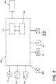
- the combination washer/dryer 10 also includes a control system for controlling the operation of the combination washer/dryer 10 to implement one or more cycles of operation.
- the control system can include a controller 106 located within the cabinet 12 and a user interface 108 that is operably coupled with the controller 106.
- the user interface 108 can provide an input and output function for the controller 106.
- the user interface 108 can be provided or integrated with the door assembly 24.
- the user interface 108 can be provided on a front panel of the cabinet 12.
- the user interface 108 can include one or more knobs, dials, switches, displays, touch screens and the like for communicating with the user, such as to receive input and provide output.
- the displays can include any suitable communication technology including that of a liquid crystal display (LCD), a light-emitting diode (LED) array, or any suitable display that can convey a message to the user.
- the user can enter different types of information including, without limitation, cycle selection and cycle parameters, such as cycle options.
- Other communications paths and methods can also be included in the combination washer/dryer 10 and can allow the controller 106 to communicate with the user in a variety of ways.
- the controller 106 can be configured to send a text message to the user, send an electronic mail to the user, or provide audio information to the user either through the combination washer/dryer 10 or utilizing another device such as a mobile phone.
- the controller 106 can include the machine controller and any additional controllers provided for controlling any of the components of the combination washer/dryer 10.
- the controller 106 can include the machine controller and a motor controller.
- Many known types of controllers can be used for the controller 106.
- the controller is a microprocessor-based controller that implements control software and sends/receives one or more electrical signals to/from each of the various working components to affect the control software.
- proportional control (P), proportional integral control (PI), and proportional derivative control (PD), or a combination thereof, a proportional integral derivative control (PID control) can be used to control the various components.
- the controller 106 can be provided with a memory 110 and a central processing unit (CPU) 112.
- the memory 110 can be used for storing the control software that is executed by the CPU 112 in completing a cycle of operation using the combination washer/dryer 10 and any additional software. Examples, without limitation, of cycles of operation include: wash, heavy duty wash, delicate wash, quick wash, pre-wash, refresh, rinse only, timed wash, dry, heavy duty dry, delicate dry, quick dry, or automatic dry, which can be selected at the user interface 108.
- the memory 110 can also be used to store information, such as a database or table, and to store data received from one or more components of the combination washer/dryer 10 that can be communicably coupled with the controller 106.
- the database or table can be used to store the various operating parameters for the one or more cycles of operation, including factory default values for the operating parameters and any adjustments to them by the control system or by user input.
- the controller 106 can be operably coupled with one or more components of the combination washer/dryer 10 for communicating with and controlling the operation of the component to complete a cycle of operation.
- the controller 106 can be operably coupled with the valves 32, 34 and the diverter mechanisms 38, 40 for controlling the temperature and flow rate of treating liquid into the treating chamber 18, the motor 78 for controlling the direction and speed of rotation of the drum 16, the pump 64 for controlling the amount of treating liquid in the treating chamber 18 or sump 60, the treating chemistry dispenser 52 for controlling the flow of treating chemistries into the treating chamber 18, the user interface 108 for receiving user selected inputs and communicating information to the user, the steam generator 72, the sump heater 74, and the drying air circuit 90, including the blower 98 and the heating portion 100, to control the operation of these and other components to implement one or more of the cycles of operation.
- the controller 106 can also be coupled with one or more sensors 104 provided in one or more of the assemblies of the combination washer/dryer 10 to receive input from the sensors 104, which are known in the art and not shown for simplicity.
- sensors 104 that can be communicably coupled with the controller 106 include: a treating chamber temperature sensor, such as a thermistor, which can detect the temperature of the treating liquid in the treating chamber 18 and/or the temperature of the treating liquid being supplied to the treating chamber 18, a moisture sensor, a weight sensor, a chemical sensor, a position sensor, an imbalance sensor, a load size sensor, and a motor torque sensor, which can be used to determine a variety of assembly and laundry characteristics, such as laundry load inertia or mass.
- a characteristic determined by the controller 106 based on input from sensors 104 can include a determination of whether treating chemistry has been added to a single dose dispenser prior to beginning a cycle of operation.
- FIG. 3A is a flowchart of a method of operating a lint cleanout routine (LCR) 130 in the combination washer/dryer 10.
- LCR 130 can be implemented automatically as part of a wash cycle, or can be implemented manually when a user selects a LCR 130 at the user interface 108.
- the user interface could have a user input allowing the user to select an LCR, allowing the user the run the routine at any time.
- the LCR 130 comprises a fill 132, a rotate 134, and a drain 136. At the filling 132, a charge of water is added to the tub 14.
- the rotating 134 comprises rotating the drum 16 at a predetermined speed for a predetermined length of time to result in dynamic or turbulent water passing across the filter 93 to dislodge lint from the filter 93.
- lint and water from the lint cleanout routine 130 are drained from the sump 60 by the pump 64 via the drain conduit 66.
- FIG. 3B schematically illustrates the LCR 130 in the combination washer/dryer 10.
- the LCR 130 begins with the fill 132 with a charge of water 138 added to the tub 14 that is sufficient to partially immerse the drum 16, but not immerse the filter 93.
- a charge of water will be 60 deciliters (about 1.58 US gallons), which is less than the amount of water for a typical treating cycle of operation.
- the amount of water is dependent on the size of the tub and drum, the location of the drum in the tub, and the location of the filter 93 relative to the drum.
- rotating is initiated at 134, where the drum 16 rotated such that the drum 16 interacts with the water 138 to impart sloshing of a portion 140 of the water 138 onto the filter 93.
- the drum 16 rotated such that the drum 16 interacts with the water 138 to impart sloshing of a portion 140 of the water 138 onto the filter 93.
- the rotating 134 is intended to create some type of water movement that will remove the lint from the filter. While the movement of the water is accomplished by rotating the drum 16, it is contemplated that other devices could be used to effect such movement of the water, including dedicated devices such as a baffle, stirrer or pressurized air.
- a draining 136 is implemented to remove the lint-laden water from the tub.
- the draining can be accomplished by energizing the drain pump and draining the lint-laden water out the drain conduit 66.
- the amount of water 138 required for the fill 132 can be varied from that described.
- the amount of water needed can be machine dependent and is the amount of water 138 required to interact with the drum 16, or other water moving device, to sufficiently dislodge at least some of the lint from the filter 93.
- the amount of water should immerse enough of the drum such that rotation of the drum will move the water to wash the lint from the filter. Additional water is not needed and will create an additional load on the motor while it tries to rotate the drum through the water. That said, if a powerful enough motor were available, the amount of water could fully or partially immerse the filter 93.
- immersing of the filter 93 undesirably consumes more resources in that more water is used and the motor would consume more electricity to move the greater amount of water as compared to the water level where the inlet is not immersed.
- the filter 93 is at the treating chamber air outlet 94 which is fluidly connected to the condenser 96, immersing the filter 93 in the water 138 could result in water entering the treating chamber air outlet 94 or the condenser 96 which may result in decreased efficiency of the drying air circuit 90 due to the presence of water in the drying air circuit 90 or damage to portions of the drying air circuit 90.
- the rotating 134 can be varied from what was described.
- the rotating 134 can include a single rotation cycle, or multiple rotation cycles, which may be separated by a pause or dwell, before proceeding to draining 136.
- the length of time, speed, and direction for each rotation cycle can be the same or different.
- the length of time, speed, and rotation direction of each rotation or a combination of rotations can be determined by the degree of interaction between the water 138 of the filling 132 and the filter 93 required to impart the amount of sloshing required to dislodge lint from the filter 93.
- the required turbulence of the water 138 to dislodge lint from the filter 93 can also determine the speed and direction of rotation of the drum 16 during each rotation.
- the drum 16 can be rotated counterclockwise, clockwise, in a reciprocating fashion alternating between counterclockwise and clockwise, or a combination.
- Some laundry treating appliances include only a single water supply fluidly connecting the household water supply to the treating chamber, with the single water supply passing through the treating chemistry dispenser for use in carrying the treating chemistry to the treating chamber.
- any treating chemistry in the dispenser would be flushed from the dispenser into the tub during the filling 132 and drained out of the appliance during the draining 136. Flushing the treating chemistry prior to a wash cycle would result in running the cycle without treating chemistry and wastes treating chemistry by simply flushing it out of the appliance.
- a treating chemistry dispenser contains treating chemistry prior to initiating an LCR. If the treating chemistry dispenser does contain treating chemistry, then the LCR can be delayed to avoid prematurely flushing treating chemistry from the dispenser.
- the method 120 begins when any type of wash cycle is selected by a user at 122.
- the controller 106 determines whether the previous cycle performed by the combination washer/dryer 10 was or included any type of a dry cycle. If a dry cycle was not previously run, then there wouldn't be any appreciable collection of lint on the filter and there is no need to run the LCR 130. When it is determined that no dry cycle was previously run, then the LCR is not implemented and the selected wash cycle is run at 128.
- a dry cycle of any type was previously run, then execution of the LCR 130 is desirable and decision control is passed to a check at 126 to determine if there is treating chemistry in a single dose dispenser which would be undesirably flushed out by executing the LCR 130.
- the check at 126 can be done for any machine, but is most suitable for machines with one water supply that passes through the dispenser.
- the controller 106 determines whether the single dose dispenser is "selected" for the current cycle.
- the single dose dispenser can be selected manually by a user via selection of a cycle requiring manual addition of treatment chemistry to the single dose dispenser, or a user can manually select the single dose dispenser from the user interface 108.
- the single dose dispenser can also be selected automatically upon adding treating chemistry to the single dose dispenser, for example, a sensor 53 in or near the single dose dispenser can sense the presence or the addition of treating chemistry to the single dose dispenser and send a signal to the controller 106 indicating the presence of treating chemistry in the single dose dispenser. If the single dose dispenser is not selected, then the LCR 130 is initiated, after which the method proceeds to the selected wash cycle at 128. If the single dose dispenser is selected, the LCR 130 will not be initiated and the method continues to the selected wash cycle 128.
- Some laundry treating appliances can include a secondary water supply or 'fresh fill' that is not fluidly connected to a treating chemistry dispenser.
- the LCR 130 can be initiated without premature flushing of treating chemistry from the dispenser.
- the combination washer/dryer 10 can have a secondary water supply via the second diverter mechanism 40 and the spray nozzle 46 configured to supply water from the household supply 30 directly to the tub 14, or to a condenser valve inlet. Since the secondary water supply can be configured to bypass the single dose dispenser, the method 120 can simply determine whether the previous cycle was a dry cycle at 124, and if yes, then the method can proceed to the LCR 130 prior to running the selected wash cycle 128.
- the controller 106 can determine whether a bulk dispenser has been selected for the current cycle. Selection of the bulk dispenser to dispense treating chemistry for the cycle of operation can passively indicate the non-selection of the single dose dispenser to the controller 106.
- the bulk dispenser can be selected by a user via selection of a cycle requiring bulk dispensing, manually selecting the bulk dispenser from the user interface 108, or the bulk dispenser can be selected automatically by the controller 106 if the presence of treating chemistry in the single dose dispenser is not detected by a sensor.
- selection of the bulk dispenser can provide the indication to the controller 106 that the single dose dispenser is not selected for the cycle of operation allowing water to enter the single dose dispensing chamber without the premature addition of treating chemistry to the cycle of operation, and therefore, the method 120 can initiate the lint cleanout routine (LCR) 130 prior to the wash cycle 128.
- the non-selection of the bulk dispenser can passively indicate the selection of the single dose dispenser, in which case, the method 120 does not initiate the LCR 130 and proceeds to the selected wash cycle 128.
- the method 120 can include both single dose dispenser and bulk dispenser selection detection where the controller 106 can first determine whether a bulk dispenser has been selected and then whether a single dose dispenser has been selected at 126, or vice-versa, prior to determining whether to initiate the LCR 130.
Landscapes
- Engineering & Computer Science (AREA)
- Textile Engineering (AREA)
- Chemical & Material Sciences (AREA)
- Chemical Kinetics & Catalysis (AREA)
- Detail Structures Of Washing Machines And Dryers (AREA)
- Control Of Washing Machine And Dryer (AREA)
Description
- Laundry treating appliances, such as washing machines, combination washer/dryers, refreshers, and non-aqueous systems, can have a configuration based on a rotating drum that at least partially defines a treating chamber in which laundry items are placed for treating. The laundry treating appliance can have a controller that implements a number of user-selectable, pre-programmed cycles of operation having one or more operating parameters. Hot water, cold water, or a mixture thereof, along with various treating chemistries, can be supplied to the treating chamber in accordance with the cycle of operation. In addition, hot air, cold air, or a mixture thereof can be supplied to the treating chamber in accordance with the cycle of operation and via an air flow assembly.
- In laundry treating appliances with drying systems, typically an air flow circuit moves process air through the treating chamber to evaporate water from a load of laundry items via an inlet and an outlet in the treating chamber. A filter can be placed in an air flow circuit to aid in the capture, or reduction of lint from the air flow within the laundry treating appliance.
- Document
JP 3 863167 B1 - In one aspect, the present disclosure relates to a method of removing lint from a lint filter by rotating a drum within tub to move liquid in the tub onto the lint filter. The rotation speed profile can be controlled along with the amount of liquid to effect the removal of lint from the lint filter.
- In another aspect, the present disclosure relates to a method of cleaning a lint filter in a combination washer/dryer having a tub, a controller, a drum rotatably mounted within the tub, an air conduit having a port fluidly connected to the tub, and a lint filter fluidly coupled to the portion and located in the tub. The method determines whether a previous cycle performed by the combination washer/dryer was a dry cycle, determines whether the single dose dispenser is selected for the current cycle, supplies a charge of water sufficient to at least partially immerse the drum while not immersing the lint filter and rotates the drum for a predetermined period of time if the controller determines the previous cycle was a dry cycle and the single dose dispenser is not selected.
- In the drawings:
-
FIG. 1 illustrates a schematic cross-sectional view of a laundry treating appliance illustrated as a combination washer/dryer according to an aspect of the present disclosure. -
FIG. 2 illustrates a schematic of a control system of the laundry treating appliance ofFIG. 1 according to an aspect of the present disclosure. -
FIG. 3A is a flowchart of a method of operating the laundry treating appliance ofFIG. 1 according to an aspect of the present disclosure. -
FIG. 3B is a schematic illustration of the method ofFIG. 3A . -
FIG. 4 is a diagram of a method of operating the laundry treating appliance ofFIG. 1 incorporating the method ofFIG. 3A according to an aspect of the present disclosure. - Aspects of the disclosure relate to a method of removing lint or fluff from portions of an interior of a combination washing and drying machine after a dry cycle and before a washing cycle. Laundry treating appliances can be provided with structures and functionality both for washing and drying laundry items within a single appliance. In the case of such a combination washing and drying appliance, in addition to the components provided in a traditional washing machine, additional components for drying laundry items are also provided within the appliance. Non-limiting examples of such drying components include an air flow pathway, including an air inlet and an air outlet to the tub interior, a condenser, a blower, a heating element, and a filter.
- In traditional combination washing and drying machines, lint or fluff from the laundry items can deposit on interior walls of a treating chamber as well as onto one or more filters in the air flow pathway filter drying cycle. In a subsequent washing cycle, the lint or fluff from the previous drying cycle can deposit on the laundry items during the washing cycle. Further, the accumulation of lint on the filters during operation can negatively affect performance of the laundry appliance, specifically during drying phases. The lint can, for example, accumulate at an inlet of the drying air duct (e.g., inlet of a recirculation system, or blower) and restrict the airflow from the tub to the drying air duct, therefore, reducing the drying efficiency of the laundry treating appliance and wasted energy resources. In the present disclosure, a combination washing and drying machine includes a lint cleanout routine to wash lint from the interior of the tub and the filter and drain the lint from the appliance prior to beginning the wash cycle. The lint cleanout routine can be implemented as a stand-alone cycle of operation or as an add-on to another cycle of operation.
- The present disclosure also includes a strategy for when to implement the lint clean out routine. The implementation of the lint cleanout routine is not typically needed if there has not been a drying phase or cycle of operation. While combo machines are typically run with back-to-back wash and dry cycles of operation, they can be operated with just a wash cycle of operation or just a dry cycle of operation. If a lint cleanout routine is run after a stand alone wash cycle of operation, there is little to no lint to remove and implementing the lint cleanout routine is not an efficient use of resources. Thus, the present disclosure looks to various ways of determining when a drying cycle of operation has occurred, be it stand-alone or in combination with a wash cycle of operation. The lint cleanout routine can be run after a drying cycle of operation has occurred or after a predetermined number of drying cycles.
- Laundry treating appliances are typically categorized as either a vertical axis laundry treating appliance or a horizontal axis laundry treating appliance. As used herein, the term "horizontal axis" laundry treating appliance refers to a laundry treating appliance having a rotatable drum that rotates about a generally horizontal axis relative to a surface that supports the laundry treating appliance. The drum can rotate about the axis inclined relative to the horizontal axis, with fifteen degrees of inclination being one example of the inclination. Similar to the horizontal axis laundry treating appliance, the term "vertical axis" laundry treating appliance refers to a laundry treating appliance having a rotatable drum that rotates about a generally vertical axis relative to a surface that supports the laundry treating appliance. However, the rotational axis need not be perfectly vertical to the surface. The drum can rotate about an axis inclined relative to the vertical axis, with fifteen degrees of inclination being one example of the inclination.
- Regardless of the axis of rotation, a laundry treating appliance can be top-loading or front-loading. In a top-loading laundry treating appliance, laundry items are placed into the drum through an access opening in the top of a cabinet, while in a front-loading laundry treating appliance laundry items are placed into the drum through an access opening in the front of a cabinet. If a laundry treating appliance is a top-loading horizontal axis laundry treating appliance or a front-loading vertical axis laundry treating appliance, an additional access opening is located on the drum.
-
FIG. 1 is a schematic cross-sectional view of a laundry treating appliance illustrated as a horizontal axis combination washer/dryer 10. It will be understood that the laundry treating appliance need not be a combination washing and drying laundry treating appliance, but that any suitable laundry treating appliance for treating laundry items placed therein, non-limiting examples of which include a horizontal or vertical axis clothes washer; a horizontal or vertical axis clothes dryer; a combination washing machine and dryer; a tumbling or stationary refreshing/revitalizing machine; an extractor; a non-aqueous washing apparatus; and a revitalizing machine. While the laundry treating appliance is illustrated herein as a horizontal axis, front-load laundry treating appliance, the aspects of the present disclosure can have applicability in laundry treating appliances with other configurations. The laundry treating appliance shares many features of a conventional automated clothes washer and/or dryer, which will not be described in detail herein except as necessary for a complete understanding of the exemplary aspects in accordance with the present disclosure. - The combination washer/
dryer 10 can include a structural support assembly comprising acabinet 12 which defines a housing within which a laundry holding assembly resides. Thecabinet 12 can be a housing having a chassis and/or a frame, to which decorative panels can or cannot be mounted, defining an interior, enclosing components typically found in a conventional laundry treating appliance, such as motors, pumps, fluid lines, controls, sensors, transducers, and the like. Such components will not be described further herein except as necessary for a complete understanding of the present disclosure. - The laundry holding assembly of the illustrated combination washer/
dryer 10 comprises atub 14 dynamically suspended within the structural support system of thecabinet 12 by asuitable suspension system 15, thetub 14 at least partially defining a treatingchamber 18. Arotatable drum 16 can be provided within thetub 14 to further define at least a portion of thelaundry treating chamber 18. Thedrum 16 is configured to receive a laundry load comprising articles for treatment, including, but not limited to, a hat, a scarf, a glove, a sweater, a blouse, a shirt, a pair of shorts, a dress, a sock, and a pair of pants, a shoe, an undergarment, and a jacket. - The
drum 16 can include a plurality of perforations 20 such that liquid can flow between thetub 14 and thedrum 16 through the perforations 20. It is also within the scope of the present disclosure for the laundry holding system to comprise only one receptacle with the receptacle defining thelaundry treating chamber 18 for receiving the load to be treated. At least onelifter 22 can extend from a wall of thedrum 16 to lift the laundry load received in the treatingchamber 18 while thedrum 16 rotates. - The laundry holding assembly can further include a closure, illustrated herein as a
door assembly 24 which can be movably mounted to or coupled to thecabinet 12 to selectively close both thetub 14 and thedrum 16, as well as the treatingchamber 18. By way of non-limiting example, thedoor assembly 24 can be hingedly coupled to thecabinet 12 for movement between an opened condition (not shown) and a closed condition as shown. - A bellows 26 can extend between the
tub 14 and thecabinet 12 to couple an open face of thetub 14 with thecabinet 12, with thedoor assembly 24 sealing against thebellows 26 or thecabinet 12, or both, when thedoor assembly 24 closes thetub 14. In the opened condition, thedoor assembly 24 can be spaced apart from thebellows 26 and can allow access to the treatingchamber 18. The bellows 26 can sealingly couple the open face of thetub 14 with thecabinet 12 such that liquid is not permitted to move from thetub 14 into the interior of thecabinet 12. - The combination washer/
dryer 10 can further comprise a washing circuit which can include a liquid supply system for supplying water to the combination washer/dryer 10 for use in treating laundry during a cycle of operation. The liquid supply system can include a source of water, such as ahousehold water supply 30, which can includeseparate valves valves valves inlet conduit 36 directly to thetub 14 or thedrum 16 by controlling first andsecond diverter mechanisms diverter mechanisms diverter mechanisms household water supply 30 can flow through theinlet conduit 36 to thefirst diverter mechanism 38 which can direct the flow of liquid to asupply conduit 42. Thesecond diverter mechanism 40 on thesupply conduit 42 can direct the flow of liquid to atub outlet conduit 44 which can be provided with aspray nozzle 46 configured to spray the flow of liquid into thetub 14 in a desired pattern and under a desired amount of pressure. For example, thespray nozzle 46 can be configured to dispense a flow or stream of water into thetub 14 by gravity, i.e. a non-pressurized stream. In this manner, water from thehousehold water supply 30 can be supplied directly to thetub 14. While thevalves inlet conduit 36 are illustrated exteriorly of thecabinet 12, it will be understood that these components can be internal to thecabinet 12. - The combination washer/
dryer 10 can also be provided with a dispensing system for dispensing treating chemistry to the treatingchamber 18 for use in treating the load of laundry according to a cycle of operation. The dispensing system can include a treatingchemistry dispenser 52 which can be a single dose dispenser, a bulk dispenser, or an integrated single dose and bulk dispenser and is fluidly coupled to the treatingchamber 18. Optionally, a sensor 53 can be positioned in or near thedispenser 52 to sense the presence of treating chemistry. The treatingchemistry dispenser 52 can be configured to dispense a treating chemistry directly to thetub 14 or mixed with water from the liquid supply system through a dispensingoutlet conduit 54. Further, water from thewater supply 30 can also be supplied to thetub 14 through the treating chemistry dispenser without the addition of treating chemistry. The dispensingoutlet conduit 54 can include a dispensingnozzle 56 configured to dispense the treating chemistry into thetub 14 in a desired pattern and under a desired amount of pressure. For example, the dispensingnozzle 56 can be configured to dispense a flow or stream of treating chemistry into thetub 14 by gravity, i.e. a non-pressurized stream. Water can be supplied to the treatingchemistry dispenser 52 from thesupply conduit 42 by directing thediverter mechanism 40 to direct the flow of water to a dispensingsupply conduit 58. - The treating
chemistry dispenser 52 can include multiple chambers or reservoirs for receiving doses of different treating chemistries. The treatingchemistry dispenser 52 can be implemented as a dispensing drawer that is slidably received within thecabinet 12, or within a separate dispenser housing which can be provided in thecabinet 12. The treatingchemistry dispenser 52 can be moveable between a fill position, where the treatingchemistry dispenser 52 is exterior to thecabinet 12 and can be filled with treating chemistry, and a dispense position, where the treatingchemistry dispenser 52 are interior of thecabinet 12. - Non-limiting examples of treating chemistries that can be dispensed by the dispensing system during a cycle of operation include one or more of the following: water, detergents, surfactants, enzymes, fragrances, stiffness/sizing agents, wrinkle releasers/reducers, softeners, antistatic or electrostatic agents, stain repellants, water repellants, energy reduction/extraction aids, antibacterial agents, medicinal agents, vitamins, moisturizers, shrinkage inhibitors, and color fidelity agents, and combinations thereof. The treating chemistries can be in the form of a liquid, powder, or any other suitable phase or state of matter.
- The combination washer/
dryer 10 can also include a recirculation and drain system for recirculating liquid within the laundry holding system and draining liquid from the combination washer/dryer 10. Liquid supplied to thetub 14 throughtub outlet conduit 44 and/or the dispensingsupply conduit 58 typically enters aspace 59 between thetub 14 and thedrum 16 and can flow by gravity to asump 60 formed in part by a lower portion of thetub 14. Thesump 60 can also be formed by asump conduit 62 that can fluidly couple the lower portion of thetub 14 to apump 64. Thepump 64 have an inlet fluidly coupled with thesump 60 and an outlet configured to fluidly couple to and to direct liquid to adrain conduit 66, which can drain the liquid from the combination washer/dryer 10, or to arecirculation conduit 68, which can terminate at arecirculation inlet 70. Therecirculation inlet 70 can direct the liquid from therecirculation conduit 68 into thedrum 16. Therecirculation inlet 70 can introduce the liquid into thedrum 16 in any suitable manner, such as by spraying, dripping, or providing a steady flow of liquid. In this manner, liquid provided to thetub 14, with or without treating chemistry can be recirculated into the treatingchamber 18 for treating the load of laundry within. The recirculation and drain assembly can include other types of recirculation systems. - The liquid supply and/or recirculation and drain system can be provided with a heating system which can include one or more devices for heating laundry and/or liquid supplied to the
tub 14, such as asteam generator 72, aninline heater 73, and/or asump heater 74. Liquid from thehousehold water supply 30 can be provided to thesteam generator 72 through theinlet conduit 36 by controlling thefirst diverter mechanism 38 to direct the flow of liquid to asteam supply conduit 76. Steam generated by thesteam generator 72 can be supplied to thetub 14 through asteam outlet conduit 77. Thesteam generator 72 can be any suitable type of steam generator such as a flow through steam generator or a tank-type steam generator. Alternatively, thesump heater 74 can be used to generate steam in place of or in addition to thesteam generator 72. In addition or alternatively to generating steam, thesteam generator 72 and/orsump heater 74 can be used to heat the laundry and/or liquid within thetub 14 as part of a cycle of operation. Thesump heater 74 can be provided within thesump 60 to heat liquid that collects in thesump 60. Alternatively, the heating assembly can include an in-line heater that heats the liquid as it flows through the liquid supply, dispensing, and/or recirculation assemblies. - It is noted that the illustrated suspension system, liquid supply system, recirculation and drain system, and dispensing system are shown for exemplary purposes only and are not limited to the systems shown in the drawings and described above. For example, the liquid supply, dispensing, and recirculation and pump systems can differ from the configuration shown in
FIG. 1 , such as by inclusion of other valves, conduits, treating chemistry dispensers, sensors, such as water level sensors and temperature sensors, and the like, to control the flow of liquid through the combination washer/dryer 10 and for the introduction of more than one type of treating chemistry. For example, the liquid supply system can include a single valve for controlling the flow of water from the household water source. In another example, the recirculation and pump system can include two separate pumps for recirculation and draining, instead of the single pump as previously described. In yet another example, the liquid supply assembly can be configured to supply liquid into the interior of thedrum 16 or into the interior of thetub 14 not occupied by thedrum 16, such that liquid can be supplied directly to thetub 14 without having to travel through thedrum 16. - The combination washer/
dryer 10 also includes a drive system for rotating thedrum 16 within thetub 14. The drive system can include amotor 78, which can be directly coupled with thedrum 16 through adrive shaft 80 to rotate thedrum 16 about a rotational axis during a cycle of operation. Themotor 78 can be a brushless permanent magnet (BPM) motor having astator 82 and arotor 84. Alternately, themotor 78 can be coupled to thedrum 16 through a belt and a drive shaft to rotate thedrum 16, as is known in the art. Other motors, such as an induction motor or a permanent split capacitor (PSC) motor, can also be used. Themotor 78 can rotate thedrum 16 at various speeds in either rotational direction. - The
motor 78 can rotate thedrum 16 at various speeds in opposite rotational directions. In particular, themotor 78 can rotate thedrum 16 at tumbling speeds wherein the fabric items in thedrum 16 rotate with thedrum 16 from a lowest location of thedrum 16 towards a highest location of thedrum 16, but fall back to the lowest location of thedrum 16 before reaching the highest location of thedrum 16. The rotation of the fabric items with thedrum 16 can be facilitated by the at least onelifter 22. Typically, the force applied to the fabric items at the tumbling speeds is less than about 1G. Alternatively, themotor 78 can rotate thedrum 16 at spin speeds wherein the fabric items rotate with thedrum 16 without falling. The spin speeds can also be referred to as satellizing speeds or sticking speeds. Typically, the force applied to the fabric items at the spin speeds is greater than or about equal to 1G. As used herein, "tumbling" of thedrum 16 refers to rotating the drum at a tumble speed, "spinning" thedrum 16 refers to rotating thedrum 16 at a spin speed, and "rotating" of thedrum 16 refers to rotating thedrum 16 at any speed. - The combination washer/
dryer 10 can further comprise a dryingair circuit 90 fluidly coupled to the treatingchamber 18 for drying laundry items. The dryingair circuit 90 can be a closed loop circuit or an open loop circuit. The dryingair circuit 90 can comprise a treatingchamber air inlet 92 and a treatingchamber air outlet 94, and specifically can be fluidly coupled with the treatingchamber air inlet 92 and the treatingchamber air outlet 94 and configured to supply drying air through the treatingchamber 18 from the treatingchamber air inlet 92 to the treatingchamber air outlet 94. While the treatingchamber air inlet 92 is illustrated herein as being provided on thebellows 26, it will be understood that the treatingchamber air inlet 92 can be any provided at any suitable position of the treatingchamber 18, including as an opening in at least one of thedrum 16 or thetub 14. The treatingchamber air outlet 94 is illustrated herein as being provided at a rear wall of thetub 14, thedrum 16, and the treatingchamber 18, though such a position is not limiting. The treatingchamber air outlet 94 can include afilter 93 to prevent lint from entering the dryingair circuit 90. The treatingchamber air inlet 92 and the treatingchamber air outlet 94 can be provided at any suitable locations of the treatingchamber 18 so long as they are spaced from one another to allow drying air to flow through the treatingchamber 18. - In one example, the drying
air circuit 90 can be provided as a closed loop, or recirculating, dryingair circuit 90, as illustrated herein. The closed loop dryingair circuit 90 can define a drying air flow pathway, as indicated by the arrows 95, to recirculate air through the treatingchamber 18. The closed loop dryingair circuit 90 can include acondenser 96, ablower 98, aheating portion 100, and a dryingair conduit 102. Thecondenser 96 can be provided with a condenser drain conduit (not shown) that fluidly couples thecondenser 96 with thepump 64 and thedrain conduit 66. Condensed liquid collected within thecondenser 96 can flow through the condenser drain conduit to thepump 64, where it can be provided to the recirculation and drain assembly. Theblower 98 is fluidly coupled to the treatingchamber 18 such that actuation of theblower 98 supplies or circulates air through the treatingchamber 18 by flowing air from the treatingchamber air inlet 92 to the treatingchamber air outlet 94. Theheating portion 100 can enclose at least one heater or heating element (not shown) that is configured to heat recirculating air that flows through the dryingair circuit 90. In one example, the dryingair circuit 90 can be provided adjacent an upper portion of thetub 14, though it will be understood that the dryingair circuit 90 need not be provided adjacent the upper portion of thetub 14, and can be provided at any suitable location adjacent thetub 14 or the treatingchamber 18. - In one example, the drying air flow pathway 95 can pass through the components of the closed loop drying
air circuit 90 such that air exiting the treatingchamber 18 through the treatingchamber air outlet 94 flows through thecondenser 96, through theblower 98, through theheating portion 100 to be heated to become drying air, and then through the dryingair conduit 102 to enter the treatingchamber 18 through the treatingchamber air inlet 92. However, while theblower 98 is illustrated herein as being provided in between thecondenser 96 and theheating portion 100, and specifically downstream of thecondenser 96 and upstream of theheating portion 100, it will be understood that theblower 98 can be provided at any suitable location within the dryingair circuit 90 so as to drive the supply of air along the drying air flow pathway 95. By way of non-limiting example, theblower 98 can be provided between the treatingchamber air outlet 94 and thecondenser 96 or between theheating portion 100 and the treatingchamber air inlet 92. Further, while the closed loop dryingair circuit 90 is illustrated herein as including both thecondenser 96 and theheating portion 100, it will be understood that the closed loop dryingair circuit 90 could also include thecondenser 96, but not theheating portion 100, or could include theheating portion 100, but not thecondenser 96. - When the drying
air circuit 90 is provided as an open loop dryingair circuit 90, thecondenser 96 is not necessary. Alternatively, theblower 98, instead of being fluidly coupled with thecondenser 96, can be fluidly coupled with an ambient air source, which can draw ambient air either from within thecabinet 12 or from the exterior of thecabinet 12. The ambient air can be provided from theblower 98 to theheating portion 100 to be heated to be provided through the dryingair conduit 102 to enter the treatingchamber 18 through the treatingchamber air inlet 92. Air that flows through the treatingchamber 18 and gathers moisture from the laundry items within the treatingchamber 18, and is then exhausted through the treatingchamber air outlet 94 and can be exhausted to the exterior of thecabinet 12. As the drying air is not being recirculated to the treatingchamber 18, no condensing is necessary. In such an example, while theblower 98 is illustrated as being provided upstream of theheating portion 100, it will also be understood that theblower 98 can be provided between theheating portion 100 and the treatingchamber air inlet 92. Additionally or alternatively, thesame blower 98 or anadditional blower 98 can be provided downstream of the treatingchamber air outlet 94 to draw the exhaust air out of the treatingchamber 18. - The combination washer/
dryer 10 also includes a control system for controlling the operation of the combination washer/dryer 10 to implement one or more cycles of operation. The control system can include acontroller 106 located within thecabinet 12 and auser interface 108 that is operably coupled with thecontroller 106. Theuser interface 108 can provide an input and output function for thecontroller 106. In one example, theuser interface 108 can be provided or integrated with thedoor assembly 24. In another example, as shown, theuser interface 108 can be provided on a front panel of thecabinet 12. - The
user interface 108 can include one or more knobs, dials, switches, displays, touch screens and the like for communicating with the user, such as to receive input and provide output. For example, the displays can include any suitable communication technology including that of a liquid crystal display (LCD), a light-emitting diode (LED) array, or any suitable display that can convey a message to the user. The user can enter different types of information including, without limitation, cycle selection and cycle parameters, such as cycle options. Other communications paths and methods can also be included in the combination washer/dryer 10 and can allow thecontroller 106 to communicate with the user in a variety of ways. For example, thecontroller 106 can be configured to send a text message to the user, send an electronic mail to the user, or provide audio information to the user either through the combination washer/dryer 10 or utilizing another device such as a mobile phone. - The
controller 106 can include the machine controller and any additional controllers provided for controlling any of the components of the combination washer/dryer 10. For example, thecontroller 106 can include the machine controller and a motor controller. Many known types of controllers can be used for thecontroller 106. It is contemplated that the controller is a microprocessor-based controller that implements control software and sends/receives one or more electrical signals to/from each of the various working components to affect the control software. As an example, proportional control (P), proportional integral control (PI), and proportional derivative control (PD), or a combination thereof, a proportional integral derivative control (PID control), can be used to control the various components. - As illustrated in
FIG. 2 , thecontroller 106 can be provided with amemory 110 and a central processing unit (CPU) 112. Thememory 110 can be used for storing the control software that is executed by theCPU 112 in completing a cycle of operation using the combination washer/dryer 10 and any additional software. Examples, without limitation, of cycles of operation include: wash, heavy duty wash, delicate wash, quick wash, pre-wash, refresh, rinse only, timed wash, dry, heavy duty dry, delicate dry, quick dry, or automatic dry, which can be selected at theuser interface 108. Thememory 110 can also be used to store information, such as a database or table, and to store data received from one or more components of the combination washer/dryer 10 that can be communicably coupled with thecontroller 106. The database or table can be used to store the various operating parameters for the one or more cycles of operation, including factory default values for the operating parameters and any adjustments to them by the control system or by user input. - The
controller 106 can be operably coupled with one or more components of the combination washer/dryer 10 for communicating with and controlling the operation of the component to complete a cycle of operation. For example, thecontroller 106 can be operably coupled with thevalves diverter mechanisms chamber 18, themotor 78 for controlling the direction and speed of rotation of thedrum 16, thepump 64 for controlling the amount of treating liquid in the treatingchamber 18 orsump 60, the treatingchemistry dispenser 52 for controlling the flow of treating chemistries into the treatingchamber 18, theuser interface 108 for receiving user selected inputs and communicating information to the user, thesteam generator 72, thesump heater 74, and the dryingair circuit 90, including theblower 98 and theheating portion 100, to control the operation of these and other components to implement one or more of the cycles of operation. - The
controller 106 can also be coupled with one ormore sensors 104 provided in one or more of the assemblies of the combination washer/dryer 10 to receive input from thesensors 104, which are known in the art and not shown for simplicity. Non-limiting examples ofsensors 104 that can be communicably coupled with thecontroller 106 include: a treating chamber temperature sensor, such as a thermistor, which can detect the temperature of the treating liquid in the treatingchamber 18 and/or the temperature of the treating liquid being supplied to the treatingchamber 18, a moisture sensor, a weight sensor, a chemical sensor, a position sensor, an imbalance sensor, a load size sensor, and a motor torque sensor, which can be used to determine a variety of assembly and laundry characteristics, such as laundry load inertia or mass. In one example, a characteristic determined by thecontroller 106 based on input fromsensors 104 can include a determination of whether treating chemistry has been added to a single dose dispenser prior to beginning a cycle of operation. -
FIG. 3A is a flowchart of a method of operating a lint cleanout routine (LCR) 130 in the combination washer/dryer 10. It is contemplated that theLCR 130 can be implemented automatically as part of a wash cycle, or can be implemented manually when a user selects aLCR 130 at theuser interface 108. For example, the user interface could have a user input allowing the user to select an LCR, allowing the user the run the routine at any time. TheLCR 130 comprises afill 132, a rotate 134, and adrain 136. At the filling 132, a charge of water is added to thetub 14. The rotating 134 comprises rotating thedrum 16 at a predetermined speed for a predetermined length of time to result in dynamic or turbulent water passing across thefilter 93 to dislodge lint from thefilter 93. Atdrain 136, lint and water from thelint cleanout routine 130 are drained from thesump 60 by thepump 64 via thedrain conduit 66. -
FIG. 3B schematically illustrates theLCR 130 in the combination washer/dryer 10. By way of non-limiting example, theLCR 130 begins with thefill 132 with a charge ofwater 138 added to thetub 14 that is sufficient to partially immerse thedrum 16, but not immerse thefilter 93. For a typical machine, it is contemplated that such a charge of water will be 60 deciliters (about 1.58 US gallons), which is less than the amount of water for a typical treating cycle of operation. Of course, the amount of water is dependent on the size of the tub and drum, the location of the drum in the tub, and the location of thefilter 93 relative to the drum. - After filling 132 is completed, or, even during filling, 132, rotating is initiated at 134, where the
drum 16 rotated such that thedrum 16 interacts with thewater 138 to impart sloshing of aportion 140 of thewater 138 onto thefilter 93. For a typical machine, it is contemplated to rotate the drum in direction coming up toward the bottom of the filter, which would be counter-clockwise inFIG. 3B , and for approximately 30 seconds. While the motion of the water is described as "sloshing", any motion that removes the lint from thefilter 93 is acceptable. The rotating 134 is intended to create some type of water movement that will remove the lint from the filter. While the movement of the water is accomplished by rotating thedrum 16, it is contemplated that other devices could be used to effect such movement of the water, including dedicated devices such as a baffle, stirrer or pressurized air. - During or after completion of the rotating 134, a draining 136 is implemented to remove the lint-laden water from the tub. The draining can be accomplished by energizing the drain pump and draining the lint-laden water out the
drain conduit 66. - Variations to the described LCR are contemplated. For example, the amount of
water 138 required for thefill 132 can be varied from that described. The amount of water needed can be machine dependent and is the amount ofwater 138 required to interact with thedrum 16, or other water moving device, to sufficiently dislodge at least some of the lint from thefilter 93. For machines using the rotating drum to move the water, the amount of water should immerse enough of the drum such that rotation of the drum will move the water to wash the lint from the filter. Additional water is not needed and will create an additional load on the motor while it tries to rotate the drum through the water. That said, if a powerful enough motor were available, the amount of water could fully or partially immerse thefilter 93. However, such immersing of thefilter 93 undesirably consumes more resources in that more water is used and the motor would consume more electricity to move the greater amount of water as compared to the water level where the inlet is not immersed. Further, because thefilter 93 is at the treatingchamber air outlet 94 which is fluidly connected to thecondenser 96, immersing thefilter 93 in thewater 138 could result in water entering the treatingchamber air outlet 94 or thecondenser 96 which may result in decreased efficiency of the dryingair circuit 90 due to the presence of water in the dryingair circuit 90 or damage to portions of the dryingair circuit 90. - The rotating 134 can be varied from what was described. The rotating 134 can include a single rotation cycle, or multiple rotation cycles, which may be separated by a pause or dwell, before proceeding to draining 136. The length of time, speed, and direction for each rotation cycle can be the same or different. The length of time, speed, and rotation direction of each rotation or a combination of rotations can be determined by the degree of interaction between the
water 138 of the filling 132 and thefilter 93 required to impart the amount of sloshing required to dislodge lint from thefilter 93. The required turbulence of thewater 138 to dislodge lint from thefilter 93 can also determine the speed and direction of rotation of thedrum 16 during each rotation. Thedrum 16 can be rotated counterclockwise, clockwise, in a reciprocating fashion alternating between counterclockwise and clockwise, or a combination. - When or if to implement the
LCR 130 can be an issue depending on the type of laundry treating appliance. Some laundry treating appliances include only a single water supply fluidly connecting the household water supply to the treating chamber, with the single water supply passing through the treating chemistry dispenser for use in carrying the treating chemistry to the treating chamber. In this type of laundry treating appliance, since executing an LCR includes supplying water to the tub, any treating chemistry in the dispenser would be flushed from the dispenser into the tub during the filling 132 and drained out of the appliance during the draining 136. Flushing the treating chemistry prior to a wash cycle would result in running the cycle without treating chemistry and wastes treating chemistry by simply flushing it out of the appliance. Given that flushing treating chemistry out of the laundry treating appliance prior to a wash cycle is not desirable, it is prudent to determine if a treating chemistry dispenser contains treating chemistry prior to initiating an LCR. If the treating chemistry dispenser does contain treating chemistry, then the LCR can be delayed to avoid prematurely flushing treating chemistry from the dispenser. - Referring now to
FIG. 4 , amethod 120 of operating thecontroller 106 to determine when or if to run the lint cleanout routine (LCR) 130 is described. Themethod 120 begins when any type of wash cycle is selected by a user at 122. At 124, thecontroller 106 determines whether the previous cycle performed by the combination washer/dryer 10 was or included any type of a dry cycle. If a dry cycle was not previously run, then there wouldn't be any appreciable collection of lint on the filter and there is no need to run theLCR 130. When it is determined that no dry cycle was previously run, then the LCR is not implemented and the selected wash cycle is run at 128. - If a dry cycle of any type was previously run, then execution of the
LCR 130 is desirable and decision control is passed to a check at 126 to determine if there is treating chemistry in a single dose dispenser which would be undesirably flushed out by executing theLCR 130. The check at 126 can be done for any machine, but is most suitable for machines with one water supply that passes through the dispenser. For the check at 126, thecontroller 106 determines whether the single dose dispenser is "selected" for the current cycle. The single dose dispenser can be selected manually by a user via selection of a cycle requiring manual addition of treatment chemistry to the single dose dispenser, or a user can manually select the single dose dispenser from theuser interface 108. The single dose dispenser can also be selected automatically upon adding treating chemistry to the single dose dispenser, for example, a sensor 53 in or near the single dose dispenser can sense the presence or the addition of treating chemistry to the single dose dispenser and send a signal to thecontroller 106 indicating the presence of treating chemistry in the single dose dispenser. If the single dose dispenser is not selected, then theLCR 130 is initiated, after which the method proceeds to the selected wash cycle at 128. If the single dose dispenser is selected, theLCR 130 will not be initiated and the method continues to the selectedwash cycle 128. - Some laundry treating appliances can include a secondary water supply or 'fresh fill' that is not fluidly connected to a treating chemistry dispenser. In this type of laundry treating appliance, if supplying water to the
tub 14 during the filling 132 of theLCR 130 can be executed by the secondary water supply, then theLCR 130 can be initiated without premature flushing of treating chemistry from the dispenser. For example, the combination washer/dryer 10 can have a secondary water supply via thesecond diverter mechanism 40 and thespray nozzle 46 configured to supply water from thehousehold supply 30 directly to thetub 14, or to a condenser valve inlet. Since the secondary water supply can be configured to bypass the single dose dispenser, themethod 120 can simply determine whether the previous cycle was a dry cycle at 124, and if yes, then the method can proceed to theLCR 130 prior to running the selectedwash cycle 128. - Optionally, if the combination washer/
dryer 10 is equipped with bulk dispensing, thecontroller 106 can determine whether a bulk dispenser has been selected for the current cycle. Selection of the bulk dispenser to dispense treating chemistry for the cycle of operation can passively indicate the non-selection of the single dose dispenser to thecontroller 106. The bulk dispenser can be selected by a user via selection of a cycle requiring bulk dispensing, manually selecting the bulk dispenser from theuser interface 108, or the bulk dispenser can be selected automatically by thecontroller 106 if the presence of treating chemistry in the single dose dispenser is not detected by a sensor. In a combination washer/dryer 10 with only a single water inlet configured to enter the single dose dispensing chamber, selection of the bulk dispenser can provide the indication to thecontroller 106 that the single dose dispenser is not selected for the cycle of operation allowing water to enter the single dose dispensing chamber without the premature addition of treating chemistry to the cycle of operation, and therefore, themethod 120 can initiate the lint cleanout routine (LCR) 130 prior to thewash cycle 128. Conversely, the non-selection of the bulk dispenser can passively indicate the selection of the single dose dispenser, in which case, themethod 120 does not initiate theLCR 130 and proceeds to the selectedwash cycle 128. - Alternatively, the
method 120 can include both single dose dispenser and bulk dispenser selection detection where thecontroller 106 can first determine whether a bulk dispenser has been selected and then whether a single dose dispenser has been selected at 126, or vice-versa, prior to determining whether to initiate theLCR 130. - To the extent not already described, the different features and structures of the various aspects can be used in combination with others as desired. That one feature cannot be illustrated in all of the aspects is not meant to be construed that it cannot be, but is done for brevity of description. Thus, the various features of the different aspects can be mixed and matched as desired to form new aspects, whether or not the new aspects are expressly described. Combinations or permutations of features described herein are covered by this disclosure.
- It is intended that the following concepts can define at least a portion of the scope of the disclosure and that the apparatus and/or method(s) within the scope of these concepts and their equivalents be covered thereby. This disclosure should be understood to include all novel and non-obvious combinations of elements described herein, and the concepts may be presented in this or a later application to any novel and non-obvious combination of these elements. Any aspect of any embodiment can be combined any aspect of any of the other embodiments. Moreover, the foregoing embodiments are illustrative, and no single feature or element is essential to all possible combinations that may be included in this or a later application.
- While the present disclosure has been specifically described in connection with certain specific aspects thereof, it is to be understood that this is by way of illustration and not of limitation. Reasonable variation and modification are possible within the scope of the forgoing disclosure and drawings without departing from the present disclosure. Hence, specific dimensions and other physical characteristics relating to the aspects disclosed herein are not to be considered as limiting, unless expressly stated otherwise.
Claims (12)
- A method of cleaning a lint filter (130) in a combination washer/dryer (10) having a tub (14), a controller (106), a drum (16) rotatably mounted within the tub (14), an air conduit (102) having a port (94) fluidly connected to the tub (14), and a lint filter (93) fluidly coupled to the port (94) and located in the tub (14), the method (130) comprising:supplying (132), to the tub (14), a charge of water sufficient to at least partially immerse the drum (16) while not immersing the lint filter (93);rotating (134) the drum (16) at a predetermined speed for a predetermined length of time to result in dynamic or turbulent water passing across the filter (93) to dislodge lint from the filter (93); anddraining the water from the laundry treating appliance,characterized in thatfurther comprises determining by the controller (106) whether a previous cycle performed by the combination washer/dryer (10) was a dry cycle,wherein the determining by the controller (106) is completed prior to initiating the supplying (132) the charge of water or rotating (134) the drum (16),wherein the supplying (132) the charge of water and rotating (134) the drum (16) occurs only if the previous cycle performed was a dry cycle.
- The method (130) of claim 1 further comprising determining by the controller (106) whether the single dose dispenser (52) is selected for the current cycle such that the single dose dispenser (52) comprises a treating chemistry.
- The method (130) of claim 2 wherein the selection of the single dose dispenser (52) comprises one of manual selection by a user via selection of a cycle requiring manual addition of treatment chemistry to the single dose dispenser (52), or, manual selection of the single dose dispenser (52) by a user from the user interface (108).
- The method (130) of claim 2 wherein the selection of the single dose dispenser (52) comprises an automatic selection upon sensing the presence of treating chemistry on the single dose dispenser (52), wherein a sensor (53) senses the presence of treating chemistry in the single dose dispenser (52).
- The method (130) of any of claims 3 or 4 wherein the determining by the controller (106) whether the single dose dispenser (52) is selected is completed prior to initiating the supplying (132) the charge of water or rotating (134) the drum (16).
- The method (130) of claim 5 wherein the supplying (132) the charge of water and rotating (134) the drum (16) occurs only if the controller (106) determines a single dose dispenser (52) is selected.
- The method (130) of claim 1 further comprising determining by the controller (106) whether the combination washer/dryer (10) comprises a secondary water supply via a second diverter mechanism (40).
- The method (130) of claim 7 wherein the secondary water supply bypasses the single dose dispenser (52).
- The method (130) of claim 8 wherein the supplying (132) the charge of water occurs through the secondary water supply.
- The method (130) of claim 1 further comprising determining by the controller (106) whether the combination washer/dryer (10) comprises a bulk dispenser (52).
- The method (130) of claim 1 wherein the method (130) is implemented automatically at the start of a user selection of a wash cycle.
- The method (130) of claim 1 wherein the method (130) is implemented manually when a user selects a lint clean out routine at the user interface (108).
Applications Claiming Priority (2)
| Application Number | Priority Date | Filing Date | Title |
|---|---|---|---|
| US201962939168P | 2019-11-22 | 2019-11-22 | |
| US17/081,386 US11905638B2 (en) | 2019-11-22 | 2020-10-27 | Laundry treating appliance for drying laundry |
Publications (2)
| Publication Number | Publication Date |
|---|---|
| EP3825452A1 EP3825452A1 (en) | 2021-05-26 |
| EP3825452B1 true EP3825452B1 (en) | 2022-06-08 |
Family
ID=73554238
Family Applications (1)
| Application Number | Title | Priority Date | Filing Date |
|---|---|---|---|
| EP20209346.4A Active EP3825452B1 (en) | 2019-11-22 | 2020-11-23 | Laundry treating appliance for drying laundry |
Country Status (3)
| Country | Link |
|---|---|
| US (3) | US11905638B2 (en) |
| EP (1) | EP3825452B1 (en) |
| CN (1) | CN112831980A (en) |
Families Citing this family (2)
| Publication number | Priority date | Publication date | Assignee | Title |
|---|---|---|---|---|
| JP7634228B2 (en) | 2021-07-27 | 2025-02-21 | 青島海爾洗衣机有限公司 | Washer/dryer |
| US12404618B2 (en) * | 2022-06-29 | 2025-09-02 | Whirlpool Corporation | Combination washing and drying laundry appliance having a filter cleaning system for removing lint during a laundry cycle |
Family Cites Families (20)
| Publication number | Priority date | Publication date | Assignee | Title |
|---|---|---|---|---|
| US2833056A (en) | 1953-03-23 | 1958-05-06 | Maytag Co | Means for treating fabrics |
| US3139633A (en) | 1960-11-14 | 1964-07-07 | Whirlpool Co | Method and means for disposing of lint in a laundry apparatus |
| GB972411A (en) | 1961-08-03 | 1964-10-14 | Borg Warner | Combination washer-dryer |
| DE19742282C1 (en) | 1997-09-25 | 1999-02-11 | Miele & Cie | Program controlled laundry appliance |
| ATE336830T1 (en) | 1999-06-25 | 2006-09-15 | Samsung Electronics Co Ltd | APPARATUS AND METHOD FOR CHANNEL CODING AND MULTIPLEXING IN A CDMA COMMUNICATIONS SYSTEM |
| DE60139172D1 (en) | 2000-03-29 | 2009-08-20 | Lg Electronics Inc | Remote controlled laundry system and method therefor |
| US8442042B2 (en) | 2005-06-09 | 2013-05-14 | Whirlpool Corporation | Appliance and a consumable holder with an embedded virtual router |
| JP3863167B1 (en) * | 2005-08-05 | 2006-12-27 | シャープ株式会社 | Dry washing machine |
| JP3939731B2 (en) | 2005-07-28 | 2007-07-04 | シャープ株式会社 | Drum-type drying washing machine |
| EP2039819B1 (en) | 2007-09-21 | 2016-05-04 | Candy S.p.A. | Washer-drier machine |
| KR20100129117A (en) | 2009-05-28 | 2010-12-08 | 엘지전자 주식회사 | Washing machine |
| DE102009046454A1 (en) * | 2009-11-06 | 2011-05-12 | BSH Bosch und Siemens Hausgeräte GmbH | Process for cleaning a washer-dryer and a suitable washer-dryer |
| CN102154805B (en) | 2011-03-11 | 2016-06-01 | 海尔集团公司 | Clothes dryer air duct jam judging method and dryer |
| RU2578117C1 (en) | 2012-04-06 | 2016-03-20 | ЭлДжи ЭЛЕКТРОНИКС ИНК. | Machine for linen processing and control method therefor |
| JP2014083138A (en) | 2012-10-22 | 2014-05-12 | Hitachi Appliances Inc | Washing and drying machine |
| US20150013075A1 (en) * | 2013-07-10 | 2015-01-15 | Whirlpool Corporation | Method of sanitization in a laundry treating appliance |
| US9469927B2 (en) | 2013-10-02 | 2016-10-18 | Whirlpool Corporation | Laundry treating appliance and method of operating a laundry treating appliance |
| AU2013405844A1 (en) * | 2013-11-20 | 2016-04-14 | Electrolux Appliances Aktiebolag | Laundry washing machine with detergent drawer comprising a control panel |
| WO2015159173A1 (en) | 2014-04-17 | 2015-10-22 | Indesit Company S.P.A. | Method for cleaning an air filter in a washing/drying machine and machine for its execution |
| DE102015223192B4 (en) | 2015-11-24 | 2025-12-04 | BSH Hausgeräte GmbH | Operating a clothes dryer with a lint filter and a lint trap |
-
2020
- 2020-10-27 US US17/081,386 patent/US11905638B2/en active Active
- 2020-11-20 CN CN202011314459.0A patent/CN112831980A/en active Pending
- 2020-11-23 EP EP20209346.4A patent/EP3825452B1/en active Active
-
2024
- 2024-02-09 US US18/437,613 patent/US12270141B2/en active Active
-
2025
- 2025-03-11 US US19/076,243 patent/US20250207314A1/en active Pending
Also Published As
| Publication number | Publication date |
|---|---|
| US11905638B2 (en) | 2024-02-20 |
| US20210156067A1 (en) | 2021-05-27 |
| US12270141B2 (en) | 2025-04-08 |
| EP3825452A1 (en) | 2021-05-26 |
| CN112831980A (en) | 2021-05-25 |
| US20240247422A1 (en) | 2024-07-25 |
| US20250207314A1 (en) | 2025-06-26 |
Similar Documents
| Publication | Publication Date | Title |
|---|---|---|
| US12060674B2 (en) | Laundry treating appliance for drying laundry | |
| US11905644B2 (en) | Laundry treating appliance having sensors, and methods of operation | |
| US11008691B2 (en) | Laundry treating appliance having an air flow assembly | |
| US20250207314A1 (en) | Laundry treating appliance for drying laundry | |
| EP3575475B1 (en) | Laundry treating appliance having a liquid distribution assembly | |
| EP3825450A1 (en) | Laundry treating appliance with a filter | |
| US20210198834A1 (en) | Laundry treating appliance having a wash water treating assembly | |
| US11828018B2 (en) | Laundry treating appliance having a condenser | |
| EP4212665A1 (en) | Laundry treating appliance having a condenser assembly | |
| EP3798353A1 (en) | Laundry treating appliance with a bellows | |
| US9469927B2 (en) | Laundry treating appliance and method of operating a laundry treating appliance | |
| US12252828B2 (en) | Combination washing and drying laundry treating appliance | |
| US12084806B2 (en) | Laundry treating appliance with a vent flap | |
| US12157965B2 (en) | Combination washer/dryer with a double-seal closure arrangement |
Legal Events
| Date | Code | Title | Description |
|---|---|---|---|
| PUAI | Public reference made under article 153(3) epc to a published international application that has entered the european phase |
Free format text: ORIGINAL CODE: 0009012 |
|
| STAA | Information on the status of an ep patent application or granted ep patent |
Free format text: STATUS: THE APPLICATION HAS BEEN PUBLISHED |
|
| AK | Designated contracting states |
Kind code of ref document: A1 Designated state(s): AL AT BE BG CH CY CZ DE DK EE ES FI FR GB GR HR HU IE IS IT LI LT LU LV MC MK MT NL NO PL PT RO RS SE SI SK SM TR |
|
| STAA | Information on the status of an ep patent application or granted ep patent |
Free format text: STATUS: REQUEST FOR EXAMINATION WAS MADE |
|
| 17P | Request for examination filed |
Effective date: 20211111 |
|
| RBV | Designated contracting states (corrected) |
Designated state(s): AL AT BE BG CH CY CZ DE DK EE ES FI FR GB GR HR HU IE IS IT LI LT LU LV MC MK MT NL NO PL PT RO RS SE SI SK SM TR |
|
| GRAP | Despatch of communication of intention to grant a patent |
Free format text: ORIGINAL CODE: EPIDOSNIGR1 |
|
| STAA | Information on the status of an ep patent application or granted ep patent |
Free format text: STATUS: GRANT OF PATENT IS INTENDED |
|
| RIC1 | Information provided on ipc code assigned before grant |
Ipc: D06F 105/48 20200101ALN20220321BHEP Ipc: D06F 103/68 20200101ALN20220321BHEP Ipc: D06F 58/22 20060101ALN20220321BHEP Ipc: D06F 33/43 20200101ALI20220321BHEP Ipc: D06F 33/32 20200101AFI20220321BHEP |
|
| GRAS | Grant fee paid |
Free format text: ORIGINAL CODE: EPIDOSNIGR3 |
|
| GRAA | (expected) grant |
Free format text: ORIGINAL CODE: 0009210 |
|
| STAA | Information on the status of an ep patent application or granted ep patent |
Free format text: STATUS: THE PATENT HAS BEEN GRANTED |
|
| INTG | Intention to grant announced |
Effective date: 20220411 |
|
| AK | Designated contracting states |
Kind code of ref document: B1 Designated state(s): AL AT BE BG CH CY CZ DE DK EE ES FI FR GB GR HR HU IE IS IT LI LT LU LV MC MK MT NL NO PL PT RO RS SE SI SK SM TR |
|
| REG | Reference to a national code |
Ref country code: AT Ref legal event code: REF Ref document number: 1496988 Country of ref document: AT Kind code of ref document: T Effective date: 20220615 Ref country code: CH Ref legal event code: EP |
|
| REG | Reference to a national code |
Ref country code: DE Ref legal event code: R096 Ref document number: 602020003473 Country of ref document: DE |
|
| REG | Reference to a national code |
Ref country code: IE Ref legal event code: FG4D |
|
| REG | Reference to a national code |
Ref country code: LT Ref legal event code: MG9D |
|
| REG | Reference to a national code |
Ref country code: NL Ref legal event code: MP Effective date: 20220608 |
|
| PG25 | Lapsed in a contracting state [announced via postgrant information from national office to epo] |
Ref country code: SE Free format text: LAPSE BECAUSE OF FAILURE TO SUBMIT A TRANSLATION OF THE DESCRIPTION OR TO PAY THE FEE WITHIN THE PRESCRIBED TIME-LIMIT Effective date: 20220608 Ref country code: NO Free format text: LAPSE BECAUSE OF FAILURE TO SUBMIT A TRANSLATION OF THE DESCRIPTION OR TO PAY THE FEE WITHIN THE PRESCRIBED TIME-LIMIT Effective date: 20220908 Ref country code: LT Free format text: LAPSE BECAUSE OF FAILURE TO SUBMIT A TRANSLATION OF THE DESCRIPTION OR TO PAY THE FEE WITHIN THE PRESCRIBED TIME-LIMIT Effective date: 20220608 Ref country code: HR Free format text: LAPSE BECAUSE OF FAILURE TO SUBMIT A TRANSLATION OF THE DESCRIPTION OR TO PAY THE FEE WITHIN THE PRESCRIBED TIME-LIMIT Effective date: 20220608 Ref country code: GR Free format text: LAPSE BECAUSE OF FAILURE TO SUBMIT A TRANSLATION OF THE DESCRIPTION OR TO PAY THE FEE WITHIN THE PRESCRIBED TIME-LIMIT Effective date: 20220909 Ref country code: FI Free format text: LAPSE BECAUSE OF FAILURE TO SUBMIT A TRANSLATION OF THE DESCRIPTION OR TO PAY THE FEE WITHIN THE PRESCRIBED TIME-LIMIT Effective date: 20220608 Ref country code: BG Free format text: LAPSE BECAUSE OF FAILURE TO SUBMIT A TRANSLATION OF THE DESCRIPTION OR TO PAY THE FEE WITHIN THE PRESCRIBED TIME-LIMIT Effective date: 20220908 |
|
| REG | Reference to a national code |
Ref country code: AT Ref legal event code: MK05 Ref document number: 1496988 Country of ref document: AT Kind code of ref document: T Effective date: 20220608 |
|
| PG25 | Lapsed in a contracting state [announced via postgrant information from national office to epo] |
Ref country code: RS Free format text: LAPSE BECAUSE OF FAILURE TO SUBMIT A TRANSLATION OF THE DESCRIPTION OR TO PAY THE FEE WITHIN THE PRESCRIBED TIME-LIMIT Effective date: 20220608 Ref country code: LV Free format text: LAPSE BECAUSE OF FAILURE TO SUBMIT A TRANSLATION OF THE DESCRIPTION OR TO PAY THE FEE WITHIN THE PRESCRIBED TIME-LIMIT Effective date: 20220608 |
|
| PG25 | Lapsed in a contracting state [announced via postgrant information from national office to epo] |
Ref country code: NL Free format text: LAPSE BECAUSE OF FAILURE TO SUBMIT A TRANSLATION OF THE DESCRIPTION OR TO PAY THE FEE WITHIN THE PRESCRIBED TIME-LIMIT Effective date: 20220608 |
|
| PG25 | Lapsed in a contracting state [announced via postgrant information from national office to epo] |
Ref country code: SM Free format text: LAPSE BECAUSE OF FAILURE TO SUBMIT A TRANSLATION OF THE DESCRIPTION OR TO PAY THE FEE WITHIN THE PRESCRIBED TIME-LIMIT Effective date: 20220608 Ref country code: SK Free format text: LAPSE BECAUSE OF FAILURE TO SUBMIT A TRANSLATION OF THE DESCRIPTION OR TO PAY THE FEE WITHIN THE PRESCRIBED TIME-LIMIT Effective date: 20220608 Ref country code: RO Free format text: LAPSE BECAUSE OF FAILURE TO SUBMIT A TRANSLATION OF THE DESCRIPTION OR TO PAY THE FEE WITHIN THE PRESCRIBED TIME-LIMIT Effective date: 20220608 Ref country code: PT Free format text: LAPSE BECAUSE OF FAILURE TO SUBMIT A TRANSLATION OF THE DESCRIPTION OR TO PAY THE FEE WITHIN THE PRESCRIBED TIME-LIMIT Effective date: 20221010 Ref country code: ES Free format text: LAPSE BECAUSE OF FAILURE TO SUBMIT A TRANSLATION OF THE DESCRIPTION OR TO PAY THE FEE WITHIN THE PRESCRIBED TIME-LIMIT Effective date: 20220608 Ref country code: EE Free format text: LAPSE BECAUSE OF FAILURE TO SUBMIT A TRANSLATION OF THE DESCRIPTION OR TO PAY THE FEE WITHIN THE PRESCRIBED TIME-LIMIT Effective date: 20220608 Ref country code: CZ Free format text: LAPSE BECAUSE OF FAILURE TO SUBMIT A TRANSLATION OF THE DESCRIPTION OR TO PAY THE FEE WITHIN THE PRESCRIBED TIME-LIMIT Effective date: 20220608 Ref country code: AT Free format text: LAPSE BECAUSE OF FAILURE TO SUBMIT A TRANSLATION OF THE DESCRIPTION OR TO PAY THE FEE WITHIN THE PRESCRIBED TIME-LIMIT Effective date: 20220608 |
|
| PG25 | Lapsed in a contracting state [announced via postgrant information from national office to epo] |
Ref country code: PL Free format text: LAPSE BECAUSE OF FAILURE TO SUBMIT A TRANSLATION OF THE DESCRIPTION OR TO PAY THE FEE WITHIN THE PRESCRIBED TIME-LIMIT Effective date: 20220608 Ref country code: IS Free format text: LAPSE BECAUSE OF FAILURE TO SUBMIT A TRANSLATION OF THE DESCRIPTION OR TO PAY THE FEE WITHIN THE PRESCRIBED TIME-LIMIT Effective date: 20221008 |
|
| REG | Reference to a national code |
Ref country code: DE Ref legal event code: R097 Ref document number: 602020003473 Country of ref document: DE |
|
| PG25 | Lapsed in a contracting state [announced via postgrant information from national office to epo] |
Ref country code: AL Free format text: LAPSE BECAUSE OF FAILURE TO SUBMIT A TRANSLATION OF THE DESCRIPTION OR TO PAY THE FEE WITHIN THE PRESCRIBED TIME-LIMIT Effective date: 20220608 |
|
| PLBE | No opposition filed within time limit |
Free format text: ORIGINAL CODE: 0009261 |
|
| STAA | Information on the status of an ep patent application or granted ep patent |
Free format text: STATUS: NO OPPOSITION FILED WITHIN TIME LIMIT |
|
| PG25 | Lapsed in a contracting state [announced via postgrant information from national office to epo] |
Ref country code: DK Free format text: LAPSE BECAUSE OF FAILURE TO SUBMIT A TRANSLATION OF THE DESCRIPTION OR TO PAY THE FEE WITHIN THE PRESCRIBED TIME-LIMIT Effective date: 20220608 |
|
| 26N | No opposition filed |
Effective date: 20230310 |
|
| PG25 | Lapsed in a contracting state [announced via postgrant information from national office to epo] |
Ref country code: SI Free format text: LAPSE BECAUSE OF FAILURE TO SUBMIT A TRANSLATION OF THE DESCRIPTION OR TO PAY THE FEE WITHIN THE PRESCRIBED TIME-LIMIT Effective date: 20220608 |
|
| P01 | Opt-out of the competence of the unified patent court (upc) registered |
Effective date: 20230523 |
|
| PG25 | Lapsed in a contracting state [announced via postgrant information from national office to epo] |
Ref country code: MC Free format text: LAPSE BECAUSE OF FAILURE TO SUBMIT A TRANSLATION OF THE DESCRIPTION OR TO PAY THE FEE WITHIN THE PRESCRIBED TIME-LIMIT Effective date: 20220608 |
|
| REG | Reference to a national code |
Ref country code: BE Ref legal event code: MM Effective date: 20221130 |
|
| PG25 | Lapsed in a contracting state [announced via postgrant information from national office to epo] |
Ref country code: LU Free format text: LAPSE BECAUSE OF NON-PAYMENT OF DUE FEES Effective date: 20221123 |
|
| PG25 | Lapsed in a contracting state [announced via postgrant information from national office to epo] |
Ref country code: IE Free format text: LAPSE BECAUSE OF NON-PAYMENT OF DUE FEES Effective date: 20221123 |
|
| PG25 | Lapsed in a contracting state [announced via postgrant information from national office to epo] |
Ref country code: BE Free format text: LAPSE BECAUSE OF NON-PAYMENT OF DUE FEES Effective date: 20221130 |
|
| PGFP | Annual fee paid to national office [announced via postgrant information from national office to epo] |
Ref country code: IT Payment date: 20231130 Year of fee payment: 4 Ref country code: FR Payment date: 20231123 Year of fee payment: 4 Ref country code: DE Payment date: 20231127 Year of fee payment: 4 |
|
| PG25 | Lapsed in a contracting state [announced via postgrant information from national office to epo] |
Ref country code: CY Free format text: LAPSE BECAUSE OF FAILURE TO SUBMIT A TRANSLATION OF THE DESCRIPTION OR TO PAY THE FEE WITHIN THE PRESCRIBED TIME-LIMIT Effective date: 20220608 |
|
| PG25 | Lapsed in a contracting state [announced via postgrant information from national office to epo] |
Ref country code: MK Free format text: LAPSE BECAUSE OF FAILURE TO SUBMIT A TRANSLATION OF THE DESCRIPTION OR TO PAY THE FEE WITHIN THE PRESCRIBED TIME-LIMIT Effective date: 20220608 |
|
| PG25 | Lapsed in a contracting state [announced via postgrant information from national office to epo] |
Ref country code: TR Free format text: LAPSE BECAUSE OF FAILURE TO SUBMIT A TRANSLATION OF THE DESCRIPTION OR TO PAY THE FEE WITHIN THE PRESCRIBED TIME-LIMIT Effective date: 20220608 |
|
| REG | Reference to a national code |
Ref country code: CH Ref legal event code: PL |
|
| PG25 | Lapsed in a contracting state [announced via postgrant information from national office to epo] |
Ref country code: CH Free format text: LAPSE BECAUSE OF NON-PAYMENT OF DUE FEES Effective date: 20231130 |
|
| PG25 | Lapsed in a contracting state [announced via postgrant information from national office to epo] |
Ref country code: CH Free format text: LAPSE BECAUSE OF NON-PAYMENT OF DUE FEES Effective date: 20231130 |
|
| PG25 | Lapsed in a contracting state [announced via postgrant information from national office to epo] |
Ref country code: MT Free format text: LAPSE BECAUSE OF FAILURE TO SUBMIT A TRANSLATION OF THE DESCRIPTION OR TO PAY THE FEE WITHIN THE PRESCRIBED TIME-LIMIT Effective date: 20220608 |
|
| PG25 | Lapsed in a contracting state [announced via postgrant information from national office to epo] |
Ref country code: BG Free format text: LAPSE BECAUSE OF FAILURE TO SUBMIT A TRANSLATION OF THE DESCRIPTION OR TO PAY THE FEE WITHIN THE PRESCRIBED TIME-LIMIT Effective date: 20220608 |
|
| PG25 | Lapsed in a contracting state [announced via postgrant information from national office to epo] |
Ref country code: BG Free format text: LAPSE BECAUSE OF FAILURE TO SUBMIT A TRANSLATION OF THE DESCRIPTION OR TO PAY THE FEE WITHIN THE PRESCRIBED TIME-LIMIT Effective date: 20220608 |
|
| REG | Reference to a national code |
Ref country code: DE Ref legal event code: R119 Ref document number: 602020003473 Country of ref document: DE |
|
| GBPC | Gb: european patent ceased through non-payment of renewal fee |
Effective date: 20241123 |
|
| PG25 | Lapsed in a contracting state [announced via postgrant information from national office to epo] |
Ref country code: HU Free format text: LAPSE BECAUSE OF FAILURE TO SUBMIT A TRANSLATION OF THE DESCRIPTION OR TO PAY THE FEE WITHIN THE PRESCRIBED TIME-LIMIT; INVALID AB INITIO Effective date: 20201123 |
|
| PG25 | Lapsed in a contracting state [announced via postgrant information from national office to epo] |
Ref country code: DE Free format text: LAPSE BECAUSE OF NON-PAYMENT OF DUE FEES Effective date: 20250603 |
|
| PG25 | Lapsed in a contracting state [announced via postgrant information from national office to epo] |
Ref country code: IT Free format text: LAPSE BECAUSE OF NON-PAYMENT OF DUE FEES Effective date: 20241123 |
|
| PG25 | Lapsed in a contracting state [announced via postgrant information from national office to epo] |
Ref country code: GB Free format text: LAPSE BECAUSE OF NON-PAYMENT OF DUE FEES Effective date: 20241123 |
|
| PG25 | Lapsed in a contracting state [announced via postgrant information from national office to epo] |
Ref country code: FR Free format text: LAPSE BECAUSE OF NON-PAYMENT OF DUE FEES Effective date: 20241130 |