EP3825439A1 - Hot filament cvd device - Google Patents
Hot filament cvd device Download PDFInfo
- Publication number
- EP3825439A1 EP3825439A1 EP19859554.8A EP19859554A EP3825439A1 EP 3825439 A1 EP3825439 A1 EP 3825439A1 EP 19859554 A EP19859554 A EP 19859554A EP 3825439 A1 EP3825439 A1 EP 3825439A1
- Authority
- EP
- European Patent Office
- Prior art keywords
- filament
- filaments
- chamber
- cartridge
- frame
- Prior art date
- Legal status (The legal status is an assumption and is not a legal conclusion. Google has not performed a legal analysis and makes no representation as to the accuracy of the status listed.)
- Pending
Links
- 238000004050 hot filament vapor deposition Methods 0.000 title claims abstract description 67
- 239000000463 material Substances 0.000 claims abstract description 50
- 239000011248 coating agent Substances 0.000 claims description 30
- 238000000576 coating method Methods 0.000 claims description 30
- 238000003780 insertion Methods 0.000 claims description 11
- 230000037431 insertion Effects 0.000 claims description 11
- 230000007246 mechanism Effects 0.000 claims description 11
- 230000008859 change Effects 0.000 claims description 6
- 238000000926 separation method Methods 0.000 claims description 4
- 238000010438 heat treatment Methods 0.000 description 26
- 239000007789 gas Substances 0.000 description 11
- 229910003460 diamond Inorganic materials 0.000 description 10
- 239000010432 diamond Substances 0.000 description 10
- 239000010409 thin film Substances 0.000 description 7
- VNWKTOKETHGBQD-UHFFFAOYSA-N methane Chemical compound C VNWKTOKETHGBQD-UHFFFAOYSA-N 0.000 description 6
- 238000000034 method Methods 0.000 description 6
- 239000010408 film Substances 0.000 description 5
- UFHFLCQGNIYNRP-UHFFFAOYSA-N Hydrogen Chemical compound [H][H] UFHFLCQGNIYNRP-UHFFFAOYSA-N 0.000 description 4
- 229930195733 hydrocarbon Natural products 0.000 description 4
- 150000002430 hydrocarbons Chemical class 0.000 description 4
- 229910052739 hydrogen Inorganic materials 0.000 description 4
- 239000001257 hydrogen Substances 0.000 description 4
- OKTJSMMVPCPJKN-UHFFFAOYSA-N Carbon Chemical compound [C] OKTJSMMVPCPJKN-UHFFFAOYSA-N 0.000 description 3
- 238000005259 measurement Methods 0.000 description 3
- 239000004215 Carbon black (E152) Substances 0.000 description 2
- YZCKVEUIGOORGS-UHFFFAOYSA-N Hydrogen atom Chemical compound [H] YZCKVEUIGOORGS-UHFFFAOYSA-N 0.000 description 2
- 239000008186 active pharmaceutical agent Substances 0.000 description 2
- 229910052799 carbon Inorganic materials 0.000 description 2
- 238000006243 chemical reaction Methods 0.000 description 2
- 238000005229 chemical vapour deposition Methods 0.000 description 2
- 238000000151 deposition Methods 0.000 description 2
- 230000008021 deposition Effects 0.000 description 2
- 238000010586 diagram Methods 0.000 description 2
- 229910052751 metal Inorganic materials 0.000 description 2
- 239000002184 metal Substances 0.000 description 2
- 230000005855 radiation Effects 0.000 description 2
- 230000004044 response Effects 0.000 description 2
- 238000005979 thermal decomposition reaction Methods 0.000 description 2
- 150000001722 carbon compounds Chemical class 0.000 description 1
- 239000000919 ceramic Substances 0.000 description 1
- 238000000354 decomposition reaction Methods 0.000 description 1
- 238000009429 electrical wiring Methods 0.000 description 1
- 238000002474 experimental method Methods 0.000 description 1
- 230000006870 function Effects 0.000 description 1
- 229910002804 graphite Inorganic materials 0.000 description 1
- 239000010439 graphite Substances 0.000 description 1
- 239000011810 insulating material Substances 0.000 description 1
- 239000004973 liquid crystal related substance Substances 0.000 description 1
- 238000012545 processing Methods 0.000 description 1
- 230000009257 reactivity Effects 0.000 description 1
- 239000003870 refractory metal Substances 0.000 description 1
- 239000003566 sealing material Substances 0.000 description 1
- 239000000758 substrate Substances 0.000 description 1
- 229910052715 tantalum Inorganic materials 0.000 description 1
- GUVRBAGPIYLISA-UHFFFAOYSA-N tantalum atom Chemical compound [Ta] GUVRBAGPIYLISA-UHFFFAOYSA-N 0.000 description 1
- WFKWXMTUELFFGS-UHFFFAOYSA-N tungsten Chemical compound [W] WFKWXMTUELFFGS-UHFFFAOYSA-N 0.000 description 1
- 229910052721 tungsten Inorganic materials 0.000 description 1
- 239000010937 tungsten Substances 0.000 description 1
Images






Classifications
-
- C—CHEMISTRY; METALLURGY
- C23—COATING METALLIC MATERIAL; COATING MATERIAL WITH METALLIC MATERIAL; CHEMICAL SURFACE TREATMENT; DIFFUSION TREATMENT OF METALLIC MATERIAL; COATING BY VACUUM EVAPORATION, BY SPUTTERING, BY ION IMPLANTATION OR BY CHEMICAL VAPOUR DEPOSITION, IN GENERAL; INHIBITING CORROSION OF METALLIC MATERIAL OR INCRUSTATION IN GENERAL
- C23C—COATING METALLIC MATERIAL; COATING MATERIAL WITH METALLIC MATERIAL; SURFACE TREATMENT OF METALLIC MATERIAL BY DIFFUSION INTO THE SURFACE, BY CHEMICAL CONVERSION OR SUBSTITUTION; COATING BY VACUUM EVAPORATION, BY SPUTTERING, BY ION IMPLANTATION OR BY CHEMICAL VAPOUR DEPOSITION, IN GENERAL
- C23C16/00—Chemical coating by decomposition of gaseous compounds, without leaving reaction products of surface material in the coating, i.e. chemical vapour deposition [CVD] processes
- C23C16/44—Chemical coating by decomposition of gaseous compounds, without leaving reaction products of surface material in the coating, i.e. chemical vapour deposition [CVD] processes characterised by the method of coating
- C23C16/448—Chemical coating by decomposition of gaseous compounds, without leaving reaction products of surface material in the coating, i.e. chemical vapour deposition [CVD] processes characterised by the method of coating characterised by the method used for generating reactive gas streams, e.g. by evaporation or sublimation of precursor materials
-
- C—CHEMISTRY; METALLURGY
- C23—COATING METALLIC MATERIAL; COATING MATERIAL WITH METALLIC MATERIAL; CHEMICAL SURFACE TREATMENT; DIFFUSION TREATMENT OF METALLIC MATERIAL; COATING BY VACUUM EVAPORATION, BY SPUTTERING, BY ION IMPLANTATION OR BY CHEMICAL VAPOUR DEPOSITION, IN GENERAL; INHIBITING CORROSION OF METALLIC MATERIAL OR INCRUSTATION IN GENERAL
- C23C—COATING METALLIC MATERIAL; COATING MATERIAL WITH METALLIC MATERIAL; SURFACE TREATMENT OF METALLIC MATERIAL BY DIFFUSION INTO THE SURFACE, BY CHEMICAL CONVERSION OR SUBSTITUTION; COATING BY VACUUM EVAPORATION, BY SPUTTERING, BY ION IMPLANTATION OR BY CHEMICAL VAPOUR DEPOSITION, IN GENERAL
- C23C16/00—Chemical coating by decomposition of gaseous compounds, without leaving reaction products of surface material in the coating, i.e. chemical vapour deposition [CVD] processes
- C23C16/22—Chemical coating by decomposition of gaseous compounds, without leaving reaction products of surface material in the coating, i.e. chemical vapour deposition [CVD] processes characterised by the deposition of inorganic material, other than metallic material
- C23C16/26—Deposition of carbon only
- C23C16/27—Diamond only
- C23C16/271—Diamond only using hot filaments
-
- C—CHEMISTRY; METALLURGY
- C23—COATING METALLIC MATERIAL; COATING MATERIAL WITH METALLIC MATERIAL; CHEMICAL SURFACE TREATMENT; DIFFUSION TREATMENT OF METALLIC MATERIAL; COATING BY VACUUM EVAPORATION, BY SPUTTERING, BY ION IMPLANTATION OR BY CHEMICAL VAPOUR DEPOSITION, IN GENERAL; INHIBITING CORROSION OF METALLIC MATERIAL OR INCRUSTATION IN GENERAL
- C23C—COATING METALLIC MATERIAL; COATING MATERIAL WITH METALLIC MATERIAL; SURFACE TREATMENT OF METALLIC MATERIAL BY DIFFUSION INTO THE SURFACE, BY CHEMICAL CONVERSION OR SUBSTITUTION; COATING BY VACUUM EVAPORATION, BY SPUTTERING, BY ION IMPLANTATION OR BY CHEMICAL VAPOUR DEPOSITION, IN GENERAL
- C23C16/00—Chemical coating by decomposition of gaseous compounds, without leaving reaction products of surface material in the coating, i.e. chemical vapour deposition [CVD] processes
- C23C16/44—Chemical coating by decomposition of gaseous compounds, without leaving reaction products of surface material in the coating, i.e. chemical vapour deposition [CVD] processes characterised by the method of coating
- C23C16/448—Chemical coating by decomposition of gaseous compounds, without leaving reaction products of surface material in the coating, i.e. chemical vapour deposition [CVD] processes characterised by the method of coating characterised by the method used for generating reactive gas streams, e.g. by evaporation or sublimation of precursor materials
- C23C16/4488—Chemical coating by decomposition of gaseous compounds, without leaving reaction products of surface material in the coating, i.e. chemical vapour deposition [CVD] processes characterised by the method of coating characterised by the method used for generating reactive gas streams, e.g. by evaporation or sublimation of precursor materials by in situ generation of reactive gas by chemical or electrochemical reaction
-
- C—CHEMISTRY; METALLURGY
- C23—COATING METALLIC MATERIAL; COATING MATERIAL WITH METALLIC MATERIAL; CHEMICAL SURFACE TREATMENT; DIFFUSION TREATMENT OF METALLIC MATERIAL; COATING BY VACUUM EVAPORATION, BY SPUTTERING, BY ION IMPLANTATION OR BY CHEMICAL VAPOUR DEPOSITION, IN GENERAL; INHIBITING CORROSION OF METALLIC MATERIAL OR INCRUSTATION IN GENERAL
- C23C—COATING METALLIC MATERIAL; COATING MATERIAL WITH METALLIC MATERIAL; SURFACE TREATMENT OF METALLIC MATERIAL BY DIFFUSION INTO THE SURFACE, BY CHEMICAL CONVERSION OR SUBSTITUTION; COATING BY VACUUM EVAPORATION, BY SPUTTERING, BY ION IMPLANTATION OR BY CHEMICAL VAPOUR DEPOSITION, IN GENERAL
- C23C16/00—Chemical coating by decomposition of gaseous compounds, without leaving reaction products of surface material in the coating, i.e. chemical vapour deposition [CVD] processes
- C23C16/44—Chemical coating by decomposition of gaseous compounds, without leaving reaction products of surface material in the coating, i.e. chemical vapour deposition [CVD] processes characterised by the method of coating
- C23C16/458—Chemical coating by decomposition of gaseous compounds, without leaving reaction products of surface material in the coating, i.e. chemical vapour deposition [CVD] processes characterised by the method of coating characterised by the method used for supporting substrates in the reaction chamber
Definitions
- the present invention relates to a hot filament CVD device that forms a coating film on a base material.
- a coating device for forming a coating film such as a diamond thin film on a surface of a base material include a hot filament CVD device.
- a hot filament CVD device a mixed gas of hydrocarbons (methane) and hydrogen is preheated by a filament heated to 1000 degrees or more, and the heated gas is introduced into the surface of the substrate to deposit diamond due to thermal decomposition of the hydrocarbons.
- Patent Literature 1 discloses a technique in which a workpiece (base material) is disposed inside a filament wound in a cylindrical shape to deposit a uniform diamond coating film on a surface of the workpiece having a three-dimensional shape.
- the technique uses a structural member including multiple struts and a beam in the shape of a ring connecting the multiple struts.
- a single filament is stretched around the struts and the beam of the structural member to form a heating region in a cylindrical shape.
- Patent Literature 1 JP H4-6274 A
- Patent Literature 1 describes the technique in which when a filament is broken due to repeated coating treatment, the broken filament needs to be removed from the struts and the beam in order, and a new filament needs to be stretched around the struts and the beam. This causes a problem in that working hours increase in attaching, detaching, and replacing a filament in a hot filament CVD device.
- the present invention provides a hot filament CVD device that performs coating treatment on multiple base materials.
- the hot filament CVD device includes: a chamber including a chamber body provided with an opening, and a door attached to the chamber body to seal the opening and allow the opening to be openable; a base material support disposed inside the chamber to support the multiple base materials; at least one filament cartridge insertable into the chamber through the opening in a predetermined insertion direction, the at least one filament cartridge including: multiple filaments that extend in a first direction and are disposed apart from each other in a second direction intersecting the first direction; a first frame that extends in the second direction and supports one end of each of the multiple filaments in the first direction; a second frame that extends in the second direction and supports another end of each of the multiple filaments in the first direction; and paired connecting members that connect opposite ends of the first frame in the second direction and corresponding opposite ends of the second frame in the second direction in the first direction; a power source that allows a current to flow into the multiple filaments; and a paired holding
- FIG. 1 is a perspective view of the hot filament CVD device 1 according to the present embodiment.
- FIGS. 2 to 4 are respectively a perspective view, a front view, and a plan view, illustrating the internal structure of the hot filament CVD device 1.
- FIG. 2 illustrates a chamber 2 described later that is partially eliminated.
- the hot filament CVD device 1 performs coating treatment on multiple workpieces 5 (base materials).
- the workpieces 5, for example, are each a drill blade in the present embodiment.
- cemented carbide is typically used.
- a hot filament CVD method is for forming a thin film using a product of thermal decomposition or a chemical reaction.
- the hot filament CVD method is a type of chemical vapor deposition (CVD) and uses a decomposition product or a chemical reaction of a material gas due to thermal energy emitted by a filament.
- the hot filament CVD device 1 can be suitably used for forming a carbon-based thin film, particularly a diamond thin film (polycrystalline diamond thin film).
- the hot filament CVD device 1 forms a diamond thin film on a surface of each of the workpieces 5 by the hot filament CVD method.
- a material gas for forming such a diamond thin film a mixed gas is used in which a carbon compound gas such as a hydrocarbon and a hydrogen gas are mixed.
- a mixed gas composed of 1% methane and 99% hydrogen by volume is used.
- the hot filament CVD device 1 includes the chamber 2 having an internal space.
- the chamber 2 has a chamber body 2S and a door (not illustrated).
- the chamber body 2S defines the above internal space.
- the chamber body 2S includes a bottom 20, four (multiple) legs 21, a front flange 22, a right wall 23, a top plate 24, a left wall 25, and a rear wall 26 ( FIGS. 1 and 2 ).
- the front flange 22 is provided with an opening 2H.
- the door (not illustrated) is attached to the chamber body 2S in an openable and closable manner. The door, when closed, seals the opening 2H.
- the door when opened, opens the opening 2H.
- the four legs 21 each have a lower end extended downward from the bottom 20.
- Each of the legs 21 has an air cylinder structure and can be extended and contracted.
- Each of the legs 21 has an upper end that is disposed inside the chamber 2 and connected to a stage 3 described later.
- the internal space of the chamber 2 communicates with a vacuum pump (not illustrated) to cause the internal space of the chamber 2 to be in a vacuum or a substantially vacuum state during the coating treatment.
- the hot filament CVD device 1 further includes the stage 3, multiple workpiece support blocks 4 (base material supports) for supporting the respective multiple workpieces 5, a filament electrode unit 6 (filament unit), and a fixed electrode 71 (first electrode), a movable electrode 72 (second electrode), a left support 73, and a right support 74.
- the stage 3 is disposed horizontally inside the chamber 2 and supports the multiple workpiece support blocks 4.
- the stage 3 has a rectangular shape in plan view, and the legs 21 described above are connected to four corners of a lower surface of the stage 3.
- the stage 3 moves up and down inside the chamber 2.
- the stage 3 includes a table 31 in a rectangular shape in top view.
- the table 31 is formed with a fixing portion 31S in a recessed shape to allow the multiple workpiece support blocks 4 to be disposed without gaps in the left-right direction.
- Each of the multiple workpiece support blocks 4 has a rectangular parallelepiped shape (strip shape) elongated in a front-rear direction.
- Each of the workpiece support blocks 4 is provided with multiple support holes 4H (refer to FIG. 9 ) (holes) opened in its upper surface, into each of which a workpiece 5 can be inserted in a vertical direction.
- each of the workpiece support blocks 4 is provided with two rows of groups of the multiple support holes 4H at an interval in the left-right direction, and each of the groups of multiple support holes 4H includes the multiple support holes 4H disposed at intervals in the front-rear direction. At this time, the intervals in the front-rear direction of the multiple support holes 4H are set evenly.
- the filament electrode unit 6 is disposed above the stage 3 (multiple workpieces 5) inside the chamber 2.
- the filament electrode unit 6 includes multiple filaments 60 ( FIG. 4 ). Structure of the filament electrode unit 6 will be described in more detail later.
- the fixed electrode 71 and the movable electrode 72 are disposed inside the chamber 2. As illustrated in FIGS. 2 and 4 , the fixed electrode 71 and the movable electrode 72 are disposed extending in the front-rear direction.
- the fixed electrode 71 is electrically connected to a left end (one end in a first direction) of each of the multiple filaments 60.
- the movable electrode 72 is electrically connected to a right end (the other end in the first direction) of each of the multiple filaments 60.
- the fixed electrode 71 and the movable electrode 72 are electrically connected to a heating power source 81 described later. Upon receiving electric power of the heating power source 81, the fixed electrode 71 and the movable electrode 72 allow a predetermined current to flow between the left end and the right end of each of the multiple filaments 60. As a result, the multiple filaments 60 are heated.
- the left support 73 and the right support 74 support the fixed electrode 71 and the movable electrode 72, respectively.
- the left support 73 and the right support 74 electrically connect the heating power source 81 and the filament electrode unit 6.
- electrical wiring (not illustrated) is provided inside the left support 73 and the right support 74.
- the left support 73 includes a left outer support 731 exposed to the outside of the chamber 2 and a left inner support 732 located inside the chamber 2 ( FIG. 3 ).
- the right support 74 includes a right outer support 741 exposed to the outside of the chamber 2 and a right inner support 742 located inside the chamber 2.
- the right inner support 742 of the right support 74 includes an extendable cylinder structure.
- the right inner support 742 extends and contracts inside the chamber 2 in response to a driving force generated by an electrode drive unit 82 ( FIG. 5 ) described later. As a result, the movable electrode 72 can be moved in the left-right direction inside the chamber 2 (refer to arrow DR in FIG. 4 ).
- through holes 23H and 25H through which the left support 73 and the right support 74 pass are opened in the right side wall 23 and the left side wall 25 of the chamber 2, respectively. Gaps between the through holes and the corresponding supports are sealed with a sealing material (not illustrated).
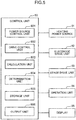
- FIG. 5 is an electrical block diagram of the hot filament CVD device 1 according to the present embodiment.
- the hot filament CVD device 1 further includes a control unit 80.
- the control unit 80 comprehensively controls operation of the hot filament CVD device 1, and is electrically connected to transmission-reception destinations of a control signal, such as the heating power source 81 (power source), the electrode drive unit 82 (holding part moving mechanism), the stage drive unit 83 (stage moving mechanism), an operation unit 84, and a display 85.
- the control unit 80 is also electrically connected to other units provided in the hot filament CVD device 1.
- the hot filament CVD device 1 also includes a control unit of a gas flow rate (not illustrated), and the like.
- the heating power source 81 allows a predetermined current to flow through the fixed electrode 71 and the movable electrode 72 so that the multiple filaments 60 are heated to about 2000°C to 2500°C.
- a high-frequency pulse power source having stable DC characteristics is desirably used.
- the electrode drive unit 82 includes a motor and a gear mechanism (not illustrated). The electrode drive unit 82 generates a driving force for moving the movable electrode 72 inside the chamber 2. The electrode drive unit 82 is connected to the right support 74.
- the stage drive unit 83 includes a motor and a gear mechanism (not illustrated).
- the stage drive unit 83 generates a driving force for moving the stage 3 up and down inside the chamber 2.
- the stage drive unit 83 is connected to the four legs 21.
- the operation unit 84 is formed of an operation panel (not illustrated) and accepts various operations for controlling the hot filament CVD device 1.
- the display 85 is formed of a liquid crystal panel (not illustrated) and displays information on various movements of the hot filament CVD device 1, for example.
- the control unit 80 is configured by a central processing unit (CPU), a read only memory (ROM) for storing a control program, a random access memory (RAM) used as a work area of the CPU, and the like, and operates to functionally include a power source control unit 801, a drive control unit 802, a calculation unit 803, a determination unit 804, a storage unit 805, and an output unit 806, when the CPU executes the control program.
- CPU central processing unit
- ROM read only memory
- RAM random access memory
- the power source control unit 801 controls the heating power source 81 according to operation information input to the operation unit 84.
- the power source control unit 801 controls output (kW), heating time, and the like of the heating power source 81.
- the drive control unit 802 causes the electrode drive unit 82 according to the operation information input to the operation unit 84 to move the movable electrode 72 to left and right.
- the drive control unit 802 causes the stage drive unit 83 according to the operation information input to the operation unit 84 to move the stage 3 up and down.
- the calculation unit 803 calculates the amount of thermal expansion of the filaments 60 in accordance with heating time of the filaments 60.
- the calculation unit 803 also calculates the amount of movement setting of the movable electrode 72 based on the amount of thermal expansion.
- the determination unit 804 determines disconnection of the filaments 60 based on change in a current value of the heating power source 81. When the determination unit 804 determines that the filament 60 is disconnected, information on the disconnection is displayed on the display 85.
- the storage unit 805 stores various parameters, threshold information, and the like for controlling the hot filament CVD device 1. As an example, the storage unit 805 stores parameters for the calculation unit 803 to calculate the amount of thermal expansion of each of the filaments 60.
- the output unit 806 outputs various command signals according to the control of the heating power source 81 and the electrode drive unit 82, being performed by the power source control unit 801 and the drive control unit 802.
- FIGS. 6 and 7 are each a perspective view of the filament electrode unit 6 including the multiple cartridges according to the present embodiment.
- FIG. 8 is a sectional view of a connecting member 63 of the filament electrode unit 6.
- the filament electrode unit 6 includes a first cartridge 6A, a second cartridge 6B, and a third cartridge 6C (multiple filament cartridges).
- the first cartridge 6A, the second cartridge 6B, and the third cartridge 6C each have the same structure.
- Each of the cartridges can be mounted inside the chamber 2 through the opening 2H ( FIG. 1 ) with the door open.
- the first cartridge 6A includes the multiple filaments 60, the left frame 61 (first frame), the right frame 62 (second frame), and paired connecting members 63.
- Each of the cartridges can be mounted in the chamber 2 even when it is flipped horizontally.
- the multiple filaments 60 extend in the left-right direction (first direction) and are disposed apart from each other in the front-rear direction (second direction intersecting the first direction).
- a wire made of a refractory metal such as tungsten or tantalum, having a wire diameter of 0.05 mm to 1.0 mm, is used.
- Each of the filament cartridges is provided with 20 filaments 60.
- the left frame 61 is a member extending in the front-rear direction and supports left ends of the multiple filaments 60.
- the left frame 61 includes a left frame front end portion 611, a left frame rear end portion 612, and multiple filament engaging portions 613.
- the left frame front end portion 611 is disposed at a front end of the left frame 61 and supports a left end portion of the connecting member 63 on a front side.
- the left frame rear end portion 612 is disposed at a rear end of the left frame 61 and supports a left end portion of the connecting member 63 on a rear side.
- the multiple filament engaging portions 613 each engage a left end portion of the corresponding one of the filaments 60 (refer to FIG. 13 ).
- the right frame 62 is a member extending in the front-rear direction and supports right ends of the multiple filaments 60.
- the right frame 62 includes a right frame front end portion 621, a right frame rear end portion 622, and multiple filament engaging portions (not illustrated, similar to the filament locking portions 613 described above).
- the right frame front end portion 621 is disposed at a front end of the right frame 62 and supports a right end portion of the connecting member 63 on the front side.
- the right frame rear end portion 622 is disposed at a rear end of the right frame 62 and supports a right end portion of the connecting member 63 on the rear side.
- the multiple filament engaging portions each lock a right end portion of the corresponding one of the filaments 60.
- each of the connecting members 63 connects respective opposite ends of the left frame 61 in the front-rear direction and corresponding opposite ends of the right frame 62 therein in the left-right direction.
- each of the connecting members 63 includes a first support rod 631 and a second support rod 632 that are made of metal, and an insulating bush 633.
- the first support rod 631 includes a small diameter portion 631A and a large diameter portion 631B.
- the second support rod 632 includes a leading end portion 632A.
- the large diameter portion 631B of the first support rod 631 is formed with a cavity in a cylindrical shape.
- the insulating bush 633 has a cylindrical shape and is preliminarily fitted into the cavity of the large diameter portion 631B. As illustrated in FIG. 8 , the leading end portion 632A of the second support rod 632 is inserted into the insulating bush 633 in the first support rod 631.
- the insulating bush 633 is made of an insulating material such as ceramic, and prevents electric discharge between the first support rod 631 and the second support rod 632.
- the insulating bush 633 has high slidability to the leading end portion 632A made of metal, and thus can reduce a drive load applied to the electrode drive unit 82 due to telescopic movement of each of the connecting members 63.
- the movable electrode 72 when the movable electrode 72 is moved left and right using a driving force generated by the electrode drive unit 82, the right frame 62 and the pair of front and rear second support rods 632, being connected to the movable electrode 72, move following the movable electrode 72. At this time, the leading end portion 632A of each of the second support rods 632 slides inside the insulating bush 633.
- the first cartridge 6A, the second cartridge 6B, and the third cartridge 6C each hold the multiple filaments 60 in parallel, and each of the connecting members 63 can be extended and contracted in a direction in which the filaments 60 extend.
- the large diameter portion 631B of the first support rod 631 and the leading end portion 632A of the second support rod 632 constitute a telescopic portion 63H ( FIG. 8 ) of the present invention.
- the telescopic portion 63H extends and contracts allowing a change in distance between the left frame 61 and the right frame 62.
- FIG. 9 is a front view illustrating an internal structure of the hot filament CVD device 1 according to the present embodiment, and is a front view of a state in which the filament electrode unit 6 is detached.
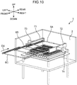
- FIG. 10 is a perspective view illustrating a state in which each cartridge of the filament electrode unit 6 is mounted on the fixed electrode 71 and the movable electrode 72.
- FIG. 11 is a perspective view illustrating a state in which each cartridge of the filament electrode unit 6 is held by the fixed electrode 71 and the movable electrode 72.
- FIG. 12 is a sectional view of the fixed electrode 71 of the hot filament CVD device 1
- FIG. 13 is a sectional view of a state in which each cartridge of the filament electrode unit 6 is held by the fixed electrode 71.
- the fixed electrode 71 and the movable electrode 72 each include a holding part for holding the filament electrode unit 6.
- the fixed electrode 71 and the movable electrode 72 are bilaterally symmetrical in shape, so that the fixed electrode 71 will be described below as an example.
- the fixed electrode 71 has a U-shape turned sideways, opening to the right, in section.
- the fixed electrode 71 includes an engaging recess 71H (holding part).
- the engaging recess 71H is formed throughout the fixed electrode 71 in the front-rear direction.
- the engaging recess 71H has an upper end portion formed with an electrode upper engaging portion 71J.
- the engaging recess 71H has a lower end portion formed with an electrode lower engaging portion 71K.
- the electrode upper engaging portion 71J has a triangular shape in section and is defined by an upper inclined portion 71J1 and an upper inner portion 71J2.
- the electrode lower engaging portion 71K has a triangular shape in section and is defined by a lower inclined portion 71K1 and a lower inner portion 71K2.
- the upper inclined portion 71J1 and the lower inclined portion 71K1 are parallel to each other and are inclined downward (to the left) toward the inside of the engaging recess 71H.
- the left frame 61 of each of the first cartridge 6A, the second cartridge 6B, and the third cartridge 6C has a shape that can be fitted into the engaging recess 71H of the fixed electrode 71. That is, the left frame 61 has an upper left end portion formed with an upper protrusion 61A and a lower left end portion formed with a lower protrusion 61B. A lower recess 61C is formed on the right of the lower protrusion 61B.
- the upper protrusion 61A and the lower protrusion 61B have inclined surfaces that are respectively in contact with the upper inclined portion 71J1 and the lower inclined portion 71K1 ( FIG. 13 ).
- the first cartridge 6A is inserted into the chamber 2 along the fixed electrode 71 while the lower protrusion 61B of the first cartridge 6A located at the lowermost position of the filament electrode unit 6 is fitted into the electrode lower engaging portion 71K ( FIG. 12 ) of the fixed electrode 71.
- the right frame 62 of the first cartridge 6A is also inserted into the chamber along the movable electrode 72 using a similar structure.
- the third cartridge 6C is inserted into the chamber 2 along the fixed electrode 71 while the upper protrusion 61A of the third cartridge 6C located at the uppermost position of the filament electrode unit 6 is fitted into the electrode upper engaging portion 71J ( FIG. 12 ) of the fixed electrode 71.
- the right frame 62 of the third cartridge 6C is also inserted into the chamber along the movable electrode 72 using a similar structure.
- the first cartridge 6A, the second cartridge 6B, and the third cartridge 6C of the filament electrode unit 6 may be inserted into the chamber 2 in this order from below as illustrated in FIGS. 6 and 10 .
- the fixed electrode 71 and the movable electrode 72 each have a shape for guiding the first cartridge 6A, the second cartridge 6B, and the third cartridge 6C that are inserted into the internal space of the chamber 2 through the opening 2H in a mounting direction (arrow DS in FIG. 10 ) parallel to the front-rear direction.
- the fixed electrode 71 and the movable electrode 72 respectively hold the left frame 61 and the right frame 62 of each of the cartridges such that the multiple filaments 60 face the corresponding multiple workpieces 5 in the vertical direction (a third direction intersecting a plane including the first direction and the second direction) ( FIGS. 3 and 4 ).
- the multiple filaments 60 of each of the first cartridge 6A, the second cartridge 6B, and the third cartridge 6C mounted in the chamber 2 are disposed at intervals in the vertical direction.
- a space is formed between the filaments 60 adjacent to each other in the left-right direction, the space passing through the first cartridge 6A, the second cartridge 6B, and the third cartridge 6C in the vertical direction.
- the workpieces 5 supported by the workpiece support blocks 4 are inserted into the space as described later.
- FIG. 14 is a perspective view illustrating an internal structure of the hot filament CVD device 1 according to the present embodiment, and is a perspective view illustrating a state of mounting the workpiece support blocks 4 on the stage 3.
- FIG. 15 is a plan view illustrating the internal structure of the hot filament CVD device 1, and is a plan view illustrating a state of mounting the workpiece support blocks 4 on the stage 3.
- the stage 3 includes the table 31.
- the table 31 is formed with the fixing portion 31S in a recessed shape ( FIG. 3 ).
- the fixing portion 31S has a width in the left-right direction that corresponds to a length acquired by adding a slight gap fitting tolerance to the sum of widths of the multiple (10) workpiece support blocks 4 in the left-right direction.
- the multiple workpiece support blocks 4 each have a rectangular parallelepiped shape extending in the front-rear direction, so that the multiple workpieces 5 ( FIG. 15 ) distributed throughout the table 31 can be divided and placed on the table 31.
- the fixing portion 31S in a recessed shape has a function of positioning the multiple workpiece support blocks 4 in the left-right direction.
- the table 31 includes a restriction portion 31T ( FIGS. 4 and 14 ) disposed at a rear end of the fixing portion 31S.
- the restriction portion 31T is a wall portion extending in the left-right direction, and regulates a rear end position of each of the workpiece support blocks 4 by being in contact with the multiple workpiece support blocks 4.
- positions of the multiple workpieces 5 supported on the corresponding multiple workpiece support blocks 4 in the front-rear and left-right directions are restricted.
- the multiple support holes 4H ( FIG. 9 ) formed in each workpiece support block 4 are opened in the workpiece support block 4 such that the multiple workpieces 5 are disposed between the corresponding multiple filaments 60 of each cartridge of the filament electrode unit 6 held by the fixed electrode 71 and the movable electrode 72 when viewed from the vertical direction (third direction).
- the fixing portion 31S of the table 31 restricts positions of the respective workpiece support blocks 4 such that the multiple workpieces 5 are disposed between the corresponding multiple filaments 60.
- FIG. 16 is a front view illustrating the internal structure of the hot filament CVD device 1 according to the present embodiment, and is a front view illustrating a state of raising the table 31 (stage 3).
- FIG. 17 is a perspective view illustrating the internal structure of the hot filament CVD device 1, and is a perspective view illustrating a state in which the table 31 is raised.
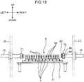
- FIG. 18 is a front view illustrating the internal structure of the hot filament CVD device 1, and is a front view illustrating a state in which the table 31 is raised.
- the coating treatment to the multiple workpieces 5 is prepared such that the filament electrode unit 6 is mounted on the fixed electrode 71 and the movable electrode 72, and the multiple workpiece support blocks 4 supporting the corresponding multiple workpieces 5 are mounted on the table 31.
- the door (not illustrated) is closed, the inside of the chamber 2 is evacuated by the vacuum pump and the mixed gas is introduced.
- the stage drive unit 83 moves the stage 3 upward (arrow DT in FIGS. 16 and 17 ).
- the multiple workpieces 5 are positioned between the corresponding multiple filaments 60 in a plane including the front-rear direction and the left-right direction.
- upward movement of the stage 3 is controlled such that the tip of each of the workpieces 5 is located between the filament 60 of the third cartridge 6C and the filament 60 of the second cartridge 6B.
- the power source control unit 801 causes the heating power source 81 to allow a current to flow into the fixed electrode 71 and the movable electrode 72 in response to operator's operation, heating of the multiple filaments 60 is started. Then, each of the filaments 60 thermally expands with the heating.
- the electrode drive unit 82 can move the movable electrode 72 in the left-right direction (extending direction of the filaments 60) as described above.
- the calculation unit 803 calculates the amount of thermal expansion ⁇ L (mm) of each of the filaments 60 from Equation 1.
- Equation 1 ⁇ ⁇ T 2 ⁇ T 1 ⁇ L
- ⁇ a coefficient of thermal expansion for each material
- T1 room temperature (°C)
- T2 the temperature of the filaments 60 measured with a radiation thermometer
- L (mm) is an original length of each of the filaments 60.
- the drive control unit 802 causes the electrode drive unit 82 to move the movable electrode 72 to the right (in the direction of pulling the filaments 60) by the amount of thermal expansion calculated by the calculation unit 803.
- the movable electrode 72 is moved by the amount of thermal expansion of the filaments 60, so that no extra tension is applied to the filaments 60.
- a central portion of each of the filaments 60 is prevented from hanging downward (deforming) due to the thermal expansion of each of the filaments 60.
- Such movement control of the movable electrode 72 (attitude control of the filaments 60) is mainly performed in an initial stage of heating where the temperature of the filaments 60 rises. Such control may be continued throughout coating treatment time for the workpieces 5.
- each of the filaments 60 reaches a predetermined heating temperature in accordance with input power of the heating power source 81, the filaments 60 heat the material gas in the chamber 2, and then graphite and other non-diamond carbons react with atomic hydrogen and evaporate.
- the atomic hydrogen reacts with an original hydrocarbon gas (methane) to form carbon-hydrogen species with high reactivity.
- methane original hydrocarbon gas
- this species decomposes, hydrogen is released, pure carbon or diamond is formed, and a diamond film is formed on each of the workpieces 5.
- each of the filaments 60 is prevented from hanging downward during the coating treatment, so that a distance between each of the filaments 60 and the corresponding one of the workpieces 5 is prevented from varying in a longitudinal direction (left-right direction) of each of the filaments 60. This prevents fluctuation in deposition speed of each of the workpieces 5 and variation in deposition result (film thickness, uniformity) from occurring depending on a position on the table 31.
- multiple filaments 60 are disposed adjacent to each other in the vertical and front-rear directions in the chamber 2 as in the present embodiment, direct measurement of temperature of each of the filaments 60 using a conventional radiation thermometer is likely to cause measurement accuracy to deteriorate. Additionally, each of the filaments 60 has a small diameter.
- the amount of thermal expansion of each of the filaments 60 is calculated in accordance with output power of the heating power source 81, and the movable electrode 72 is moved in accordance with the amount of the thermal expansion.
- control variation is reduced, an attitude of each of the filaments 60 is stably maintained, and coating quality for each of the workpieces 5 is improved.
- the filament cartridges 6A, 6B and 6C supporting the multiple filaments 60 are inserted into the chamber 2 through the opening 2H.
- the fixed electrode 71 and the movable electrode 72 guide each of the filament cartridges, so that each of the filament cartridges can be easily inserted into the chamber 2.
- the fixed electrode 71 and the movable electrode 72 also hold each of the filament cartridges in the chamber 2 so that the multiple filaments 60 face the corresponding multiple workpieces 5. This enables each of the multiple filaments 60 to be easily disposed at a coating treatment position inside the chamber 2. Additionally, when a part of the multiple filaments 60 is broken, the broken filament 60 can be easily removed by replacing the corresponding filament cartridge.
- multiple filament cartridges can be easily attached inside the chamber 2 and detached from inside the chamber 2.
- the filaments 60 of each of the multiple filament cartridges are disposed at intervals in the vertical direction, so that a coating treatment space in which each of the workpieces 5 is insertable can be formed between the filaments 60 adjacent to each other in the front-rear direction.
- each of the paired connecting members 63 of each filament cartridge has the telescopic portion 63H, so that the above deformation due to thermal expansion can be prevented while cartridge structure of the multiple filaments 60 is maintained.
- a coating treatment position of each of the workpieces 5 can be aligned with the corresponding one of the multiple filaments 60.
- each of the multiple workpieces 5 can be moved between the coating treatment position at which each of the multiple workpieces 5 is disposed close to the corresponding one of the multiple filaments 60, and a separation position disposed further apart from below the corresponding one of the multiple filaments 60 than the coating treatment position.
- the present invention is not limited to the embodiment.
- the hot filament CVD device according to the present invention the following modified embodiments are applicable.
- each of the cartridges may be inserted into the chamber 2 in the direction in which the multiple filaments 60 extend.
- the fixed electrode 71 and the movable electrode 72 of FIG. 10 may be disposed on the front side and the rear side of the chamber 2, respectively.
- any one of the electrodes to be disposed on the front side when each of the cartridges is attached or detached is desirably retracted downward or upward to prevent interference with attachment or detachment of each of the cartridges.
- the table 31 and each of the filament cartridges in the chamber 2 may be disposed in the vertical direction. That is, a structure in which the hot filament CVD device 1 in FIG. 1 is rotated 90 degrees around a horizontal axis may be used.
- the first cartridge 6A, the second cartridge 6B, and the third cartridge 6C may be each disposed with the filaments 60 each having a longitudinal direction intersecting (orthogonal to) a longitudinal direction of each of the workpiece support blocks 4.
- an electrode for applying voltage to the multiple filaments 60 may have another structure.
- paired holding parts each having an engaging recess 71H as in the above embodiment may be provided in the chamber 2, and voltage may be applied to each of the filaments 60 through a path different from the holding parts.
- the hot filament CVD device 1 may include only the cartridge structure of the filament electrode unit 6 without including a mechanism for moving the electrode (holding part).
- the workpiece support block 4 may be formed of one block placed on the table 31 without being divided into multiple blocks.
- Equation 1 (4) Although the above embodiment is described in which when the movable electrode 72 is moved in accordance with thermal expansion of the multiple filaments 60, the amount of movement of the movable electrode 72 is calculated using Equation 1, the present invention is not limited to this.
- the amount of thermal expansion of each of the filaments 60 in accordance with output of the heating power source 81 and heating time (voltage application time) of each of the filaments 60 may be preliminarily measured in an experiment (experimental data) and stored in the storage unit 805. In this case, the drive control unit 802 ( FIG.
- Equation 5 may refer to the corresponding amount of thermal expansion stored in the storage unit 805 in accordance with the output and the heating time of the heating power source 81 during the actual coating treatment, to cause the movable electrode 72 to move in accordance with the corresponding amount of thermal expansion.
- Equation 1 above and the experimental data may be combined to correct the amount of thermal expansion derived from Equation 1 using the experimental data, and movement control of the movable electrode 72, having higher accuracy of the thermal expansion of each of the filaments 60, may be performed.
- the present invention provides a hot filament CVD device that performs coating treatment on multiple base materials.
- the hot filament CVD device includes: a chamber including a chamber body provided with an opening, and a door attached to the chamber body to seal the opening and allow the opening to be openable; a base material support disposed inside the chamber to support the multiple base materials; at least one filament cartridge insertable into the chamber through the opening in a predetermined insertion direction, the at least one filament cartridge including: multiple filaments that extend in a first direction and are disposed apart from each other in a second direction intersecting the first direction; a first frame that extends in the second direction and supports one end of each of the multiple filaments in the first direction; a second frame that extends in the second direction and supports another end of each of the multiple filaments in the first direction; and paired connecting members that connect opposite ends of the first frame in the second direction and corresponding opposite ends of the second frame in the second direction in the first direction; a power source that allows a current to flow into the multiple filaments; and a paired holding
- the filament cartridge supporting the multiple filaments is inserted into the chamber through the opening.
- the paired holding parts guide the filament cartridge, so that the filament cartridge can be easily inserted into the chamber.
- the paired holding parts hold the filament cartridge in the chamber so that the multiple filaments face the corresponding multiple base materials. This enables each of the multiple filaments to be easily disposed at a coating treatment position inside the chamber. Additionally, when a part of the multiple filaments is broken, the broken filament can be easily removed by replacing the corresponding filament cartridge.
- the above configuration is desirably configured such that the at least one filament cartridge includes multiple filament cartridges, and the paired holding parts each have a shape guiding each of the multiple filament cartridges to be inserted into the chamber in the insertion direction, and holding the multiple filament cartridges allowing the multiple filaments provided in each of the multiple filament cartridges to be disposed at intervals in the third direction.
- the multiple filament cartridges can be easily attached inside the chamber and detached from inside the chamber.
- the filaments of each of the multiple filament cartridges are disposed at intervals in the third direction, so that a coating treatment space in which each of the base materials is insertable can be formed between the filaments adjacent to each other in the second direction.
- the hot filament CVD device further includes a holding part moving mechanism that moves at least one of the paired holding parts to change a distance between the first frame and the second frame in the first direction
- the paired connecting members each have a telescopic portion that is capable of being extended and contracted, allowing a change in distance between the first frame and the second frame.
- each of the paired connecting members of each filament cartridge has the telescopic portion, so that the above deformation can be prevented while the cartridge structure of the multiple filaments is maintained.
- the above configuration desirably further includes a stage that restricts a position of the base material support in each of the first direction and the second direction in the chamber, and holds the base material support, wherein the base material support opened with multiple holes into which the respective multiple base materials are allowed to be inserted, and opening positions of the respective multiple holes in the base material support are set to allow the multiple base materials to be disposed between the corresponding multiple filaments of the at least one filament cartridge held by the paired holding parts when viewed from the third direction.
- the multiple base materials can be aligned with the corresponding multiple filaments.
- the above configuration desirably further includes a stage moving mechanism that moves the stage in the third direction to move the multiple base materials between a coating treatment position at which the multiple base materials are disposed close to the corresponding multiple filaments and a separation position further apart from the multiple filaments than the coating treatment position in the third direction.
- the multiple base materials can be moved between the coating treatment position and the separation position.
Landscapes
- Chemical & Material Sciences (AREA)
- General Chemical & Material Sciences (AREA)
- Chemical Kinetics & Catalysis (AREA)
- Engineering & Computer Science (AREA)
- Materials Engineering (AREA)
- Mechanical Engineering (AREA)
- Metallurgy (AREA)
- Organic Chemistry (AREA)
- Inorganic Chemistry (AREA)
- Electrochemistry (AREA)
- Chemical Vapour Deposition (AREA)
- Crystals, And After-Treatments Of Crystals (AREA)
Abstract
Description
- The present invention relates to a hot filament CVD device that forms a coating film on a base material.
- Known examples of a coating device for forming a coating film such as a diamond thin film on a surface of a base material include a hot filament CVD device. In such a hot filament CVD device, a mixed gas of hydrocarbons (methane) and hydrogen is preheated by a filament heated to 1000 degrees or more, and the heated gas is introduced into the surface of the substrate to deposit diamond due to thermal decomposition of the hydrocarbons.
-
Patent Literature 1 discloses a technique in which a workpiece (base material) is disposed inside a filament wound in a cylindrical shape to deposit a uniform diamond coating film on a surface of the workpiece having a three-dimensional shape. The technique uses a structural member including multiple struts and a beam in the shape of a ring connecting the multiple struts. A single filament is stretched around the struts and the beam of the structural member to form a heating region in a cylindrical shape. - Patent Literature 1:
JP H4-6274 A -
Patent Literature 1 describes the technique in which when a filament is broken due to repeated coating treatment, the broken filament needs to be removed from the struts and the beam in order, and a new filament needs to be stretched around the struts and the beam. This causes a problem in that working hours increase in attaching, detaching, and replacing a filament in a hot filament CVD device. - It is an object of the present invention to provide a hot filament CVD device capable of easily attaching, detaching, and replacing a filament.
- The present invention provides a hot filament CVD device that performs coating treatment on multiple base materials. The hot filament CVD device includes: a chamber including a chamber body provided with an opening, and a door attached to the chamber body to seal the opening and allow the opening to be openable; a base material support disposed inside the chamber to support the multiple base materials; at least one filament cartridge insertable into the chamber through the opening in a predetermined insertion direction, the at least one filament cartridge including: multiple filaments that extend in a first direction and are disposed apart from each other in a second direction intersecting the first direction; a first frame that extends in the second direction and supports one end of each of the multiple filaments in the first direction; a second frame that extends in the second direction and supports another end of each of the multiple filaments in the first direction; and paired connecting members that connect opposite ends of the first frame in the second direction and corresponding opposite ends of the second frame in the second direction in the first direction; a power source that allows a current to flow into the multiple filaments; and a paired holding parts each having a shape for guiding the at least one filament cartridge in the insertion direction, the at least one filament cartridge being to be inserted into the chamber in the insertion direction through the opening, and for holding the at least one filament cartridge while allowing the multiple filaments to face the corresponding multiple base materials in a third direction intersecting a plane including the first direction and the second direction.
-
-
FIG. 1 is a perspective view of a hot filament CVD device according to an embodiment of the present invention. -
FIG. 2 is a perspective view illustrating an internal structure of the hot filament CVD device according to the embodiment of the present invention. -
FIG. 3 is a front view illustrating the internal structure of the hot filament CVD device according to the embodiment of the present invention. -
FIG. 4 is a plan view illustrating the internal structure of the hot filament CVD device according to the embodiment of the present invention. -
FIG. 5 is an electrical block diagram of the hot filament CVD device according to the embodiment of the present invention. -
FIG. 6 is a perspective view of multiple filament cartridges of the hot filament CVD device according to the embodiment of the present invention. -
FIG. 7 is a perspective view of multiple filament cartridges of the hot filament CVD device according to the embodiment of the present invention. -
FIG. 8 is a sectional view of a connecting member of the filament cartridge according to the embodiment of the present invention. -
FIG. 9 is a front view illustrating the internal structure of the hot filament CVD device according to the embodiment of the present invention, and is a front view of a state in which the filament cartridge is detached. -
FIG. 10 is a perspective view illustrating the internal structure of the hot filament CVD device according to the embodiment of the present invention, and is a perspective view illustrating a state in which the filament cartridge is attached. -
FIG. 11 is a perspective view illustrating the internal structure of the hot filament CVD device according to the embodiment of the present invention, and is a perspective view of a state in which the filament cartridge is attached. -
FIG. 12 is a sectional view of a holding part of the hot filament CVD device according to the embodiment of the present invention. -
FIG. 13 is a sectional view of a state in which the filament cartridge is supported by the holding part of the hot filament CVD device according to the embodiment of the present invention. -
FIG. 14 is a perspective view illustrating the internal structure of the hot filament CVD device according to the embodiment of the present invention, and is a perspective view illustrating a state of mounting a base material support. -
FIG. 15 is a plan view illustrating the internal structure of the hot filament CVD device according to the embodiment of the present invention, and is a plan view illustrating a state of mounting the base material support. -
FIG. 16 is a front view illustrating the internal structure of the hot filament CVD device according to the embodiment of the present invention, and is a front view illustrating a state of raising a stage. -
FIG. 17 is a perspective view illustrating the internal structure of the hot filament CVD device according to the embodiment of the present invention, and is a perspective view illustrating a state in which the stage is raised. -
FIG. 18 is a front view illustrating the internal structure of the hot filament CVD device according to the embodiment of the present invention, and is a front view illustrating a state in which the stage is raised. - Hereinafter, a hot
filament CVD device 1 according to an embodiment of the present invention will be described with reference to the drawings.FIG. 1 is a perspective view of the hotfilament CVD device 1 according to the present embodiment.FIGS. 2 to 4 are respectively a perspective view, a front view, and a plan view, illustrating the internal structure of the hotfilament CVD device 1.FIG. 2 illustrates achamber 2 described later that is partially eliminated. - The hot
filament CVD device 1 performs coating treatment on multiple workpieces 5 (base materials). Theworkpieces 5, for example, are each a drill blade in the present embodiment. As a material of each of theworkpieces 5, cemented carbide is typically used. A hot filament CVD method is for forming a thin film using a product of thermal decomposition or a chemical reaction. The hot filament CVD method is a type of chemical vapor deposition (CVD) and uses a decomposition product or a chemical reaction of a material gas due to thermal energy emitted by a filament. The hotfilament CVD device 1 can be suitably used for forming a carbon-based thin film, particularly a diamond thin film (polycrystalline diamond thin film). In the present embodiment, the hotfilament CVD device 1 forms a diamond thin film on a surface of each of theworkpieces 5 by the hot filament CVD method. As a material gas for forming such a diamond thin film, a mixed gas is used in which a carbon compound gas such as a hydrocarbon and a hydrogen gas are mixed. In the present embodiment, a mixed gas composed of 1% methane and 99% hydrogen by volume is used. - The hot
filament CVD device 1 includes thechamber 2 having an internal space. Thechamber 2 has achamber body 2S and a door (not illustrated). Thechamber body 2S defines the above internal space. Thechamber body 2S includes abottom 20, four (multiple)legs 21, afront flange 22, aright wall 23, atop plate 24, aleft wall 25, and a rear wall 26 (FIGS. 1 and2 ). Thefront flange 22 is provided with an opening 2H. The door (not illustrated) is attached to thechamber body 2S in an openable and closable manner. The door, when closed, seals the opening 2H. The door, when opened, opens the opening 2H. The fourlegs 21 each have a lower end extended downward from thebottom 20. Each of thelegs 21 has an air cylinder structure and can be extended and contracted. Each of thelegs 21 has an upper end that is disposed inside thechamber 2 and connected to astage 3 described later. The internal space of thechamber 2 communicates with a vacuum pump (not illustrated) to cause the internal space of thechamber 2 to be in a vacuum or a substantially vacuum state during the coating treatment. - The hot
filament CVD device 1 further includes thestage 3, multiple workpiece support blocks 4 (base material supports) for supporting the respectivemultiple workpieces 5, a filament electrode unit 6 (filament unit), and a fixed electrode 71 (first electrode), a movable electrode 72 (second electrode), aleft support 73, and aright support 74. - The
stage 3 is disposed horizontally inside thechamber 2 and supports the multipleworkpiece support blocks 4. Thestage 3 has a rectangular shape in plan view, and thelegs 21 described above are connected to four corners of a lower surface of thestage 3. When each of thelegs 21 is extended and contracted by astage drive unit 83 described later, thestage 3 moves up and down inside thechamber 2. Thestage 3 includes a table 31 in a rectangular shape in top view. The table 31 is formed with a fixingportion 31S in a recessed shape to allow the multiple workpiece support blocks 4 to be disposed without gaps in the left-right direction. - Each of the multiple workpiece support blocks 4 has a rectangular parallelepiped shape (strip shape) elongated in a front-rear direction. Each of the workpiece support blocks 4 is provided with
multiple support holes 4H (refer toFIG. 9 ) (holes) opened in its upper surface, into each of which aworkpiece 5 can be inserted in a vertical direction. Specifically, each of the workpiece support blocks 4 is provided with two rows of groups of themultiple support holes 4H at an interval in the left-right direction, and each of the groups ofmultiple support holes 4H includes themultiple support holes 4H disposed at intervals in the front-rear direction. At this time, the intervals in the front-rear direction of themultiple support holes 4H are set evenly. - As illustrated in
FIGS. 2 and3 , thefilament electrode unit 6 is disposed above the stage 3 (multiple workpieces 5) inside thechamber 2. Thefilament electrode unit 6 includes multiple filaments 60 (FIG. 4 ). Structure of thefilament electrode unit 6 will be described in more detail later. - The fixed
electrode 71 and themovable electrode 72 are disposed inside thechamber 2. As illustrated inFIGS. 2 and4 , the fixedelectrode 71 and themovable electrode 72 are disposed extending in the front-rear direction. The fixedelectrode 71 is electrically connected to a left end (one end in a first direction) of each of themultiple filaments 60. In contrast, themovable electrode 72 is electrically connected to a right end (the other end in the first direction) of each of themultiple filaments 60. The fixedelectrode 71 and themovable electrode 72 are electrically connected to aheating power source 81 described later. Upon receiving electric power of theheating power source 81, the fixedelectrode 71 and themovable electrode 72 allow a predetermined current to flow between the left end and the right end of each of themultiple filaments 60. As a result, themultiple filaments 60 are heated. - The
left support 73 and theright support 74 support the fixedelectrode 71 and themovable electrode 72, respectively. Theleft support 73 and theright support 74 electrically connect theheating power source 81 and thefilament electrode unit 6. Thus, electrical wiring (not illustrated) is provided inside theleft support 73 and theright support 74. Theleft support 73 includes a leftouter support 731 exposed to the outside of thechamber 2 and a leftinner support 732 located inside the chamber 2 (FIG. 3 ). Similarly, theright support 74 includes a rightouter support 741 exposed to the outside of thechamber 2 and a rightinner support 742 located inside thechamber 2. In the present embodiment, the rightinner support 742 of theright support 74 includes an extendable cylinder structure. The rightinner support 742 extends and contracts inside thechamber 2 in response to a driving force generated by an electrode drive unit 82 (FIG. 5 ) described later. As a result, themovable electrode 72 can be moved in the left-right direction inside the chamber 2 (refer to arrow DR inFIG. 4 ). - As illustrated in
FIGS. 3 and4 , throughholes left support 73 and theright support 74 pass are opened in theright side wall 23 and theleft side wall 25 of thechamber 2, respectively. Gaps between the through holes and the corresponding supports are sealed with a sealing material (not illustrated). -
FIG. 5 is an electrical block diagram of the hotfilament CVD device 1 according to the present embodiment. The hotfilament CVD device 1 further includes acontrol unit 80. Thecontrol unit 80 comprehensively controls operation of the hotfilament CVD device 1, and is electrically connected to transmission-reception destinations of a control signal, such as the heating power source 81 (power source), the electrode drive unit 82 (holding part moving mechanism), the stage drive unit 83 (stage moving mechanism), anoperation unit 84, and adisplay 85. Thecontrol unit 80 is also electrically connected to other units provided in the hotfilament CVD device 1. The hotfilament CVD device 1 also includes a control unit of a gas flow rate (not illustrated), and the like. - The
heating power source 81 allows a predetermined current to flow through the fixedelectrode 71 and themovable electrode 72 so that themultiple filaments 60 are heated to about 2000°C to 2500°C. For theheating power source 81, a high-frequency pulse power source having stable DC characteristics is desirably used. - The
electrode drive unit 82 includes a motor and a gear mechanism (not illustrated). Theelectrode drive unit 82 generates a driving force for moving themovable electrode 72 inside thechamber 2. Theelectrode drive unit 82 is connected to theright support 74. - The
stage drive unit 83 includes a motor and a gear mechanism (not illustrated). Thestage drive unit 83 generates a driving force for moving thestage 3 up and down inside thechamber 2. Thestage drive unit 83 is connected to the fourlegs 21. - The
operation unit 84 is formed of an operation panel (not illustrated) and accepts various operations for controlling the hotfilament CVD device 1. - The
display 85 is formed of a liquid crystal panel (not illustrated) and displays information on various movements of the hotfilament CVD device 1, for example. - The
control unit 80 is configured by a central processing unit (CPU), a read only memory (ROM) for storing a control program, a random access memory (RAM) used as a work area of the CPU, and the like, and operates to functionally include a powersource control unit 801, adrive control unit 802, acalculation unit 803, adetermination unit 804, astorage unit 805, and anoutput unit 806, when the CPU executes the control program. - The power
source control unit 801 controls theheating power source 81 according to operation information input to theoperation unit 84. The powersource control unit 801 controls output (kW), heating time, and the like of theheating power source 81. - The
drive control unit 802 causes theelectrode drive unit 82 according to the operation information input to theoperation unit 84 to move themovable electrode 72 to left and right. Thedrive control unit 802 causes thestage drive unit 83 according to the operation information input to theoperation unit 84 to move thestage 3 up and down. - The
calculation unit 803 calculates the amount of thermal expansion of thefilaments 60 in accordance with heating time of thefilaments 60. Thecalculation unit 803 also calculates the amount of movement setting of themovable electrode 72 based on the amount of thermal expansion. - The
determination unit 804 determines disconnection of thefilaments 60 based on change in a current value of theheating power source 81. When thedetermination unit 804 determines that thefilament 60 is disconnected, information on the disconnection is displayed on thedisplay 85. - The
storage unit 805 stores various parameters, threshold information, and the like for controlling the hotfilament CVD device 1. As an example, thestorage unit 805 stores parameters for thecalculation unit 803 to calculate the amount of thermal expansion of each of thefilaments 60. - The
output unit 806 outputs various command signals according to the control of theheating power source 81 and theelectrode drive unit 82, being performed by the powersource control unit 801 and thedrive control unit 802. - Next, structure of multiple filament cartridges according to the present embodiment will be described in more detail.
FIGS. 6 and7 are each a perspective view of thefilament electrode unit 6 including the multiple cartridges according to the present embodiment.FIG. 8 is a sectional view of a connectingmember 63 of thefilament electrode unit 6. - In the present embodiment, the
filament electrode unit 6 includes afirst cartridge 6A, asecond cartridge 6B, and athird cartridge 6C (multiple filament cartridges). Thefirst cartridge 6A, thesecond cartridge 6B, and thethird cartridge 6C each have the same structure. Each of the cartridges can be mounted inside thechamber 2 through theopening 2H (FIG. 1 ) with the door open. Hereinafter, the structure of thefirst cartridge 6A will be described as an example. Thefirst cartridge 6A includes themultiple filaments 60, the left frame 61 (first frame), the right frame 62 (second frame), and paired connectingmembers 63. Each of the cartridges can be mounted in thechamber 2 even when it is flipped horizontally. - The multiple filaments 60 (
FIG. 4 ) extend in the left-right direction (first direction) and are disposed apart from each other in the front-rear direction (second direction intersecting the first direction). For each of thefilaments 60, a wire made of a refractory metal such as tungsten or tantalum, having a wire diameter of 0.05 mm to 1.0 mm, is used. Each of the filament cartridges is provided with 20filaments 60. - The
left frame 61 is a member extending in the front-rear direction and supports left ends of themultiple filaments 60. Theleft frame 61 includes a left framefront end portion 611, a left framerear end portion 612, and multiplefilament engaging portions 613. The left framefront end portion 611 is disposed at a front end of theleft frame 61 and supports a left end portion of the connectingmember 63 on a front side. The left framerear end portion 612 is disposed at a rear end of theleft frame 61 and supports a left end portion of the connectingmember 63 on a rear side. The multiplefilament engaging portions 613 each engage a left end portion of the corresponding one of the filaments 60 (refer toFIG. 13 ). When theleft frame 61 is supported by the fixedelectrode 71, the left end portion of each of thefilaments 60 and theheating power source 81 are electrically connected to each other through the corresponding one of thefilament engaging portions 613. - Similarly, the
right frame 62 is a member extending in the front-rear direction and supports right ends of themultiple filaments 60. Theright frame 62 includes a right framefront end portion 621, a right framerear end portion 622, and multiple filament engaging portions (not illustrated, similar to thefilament locking portions 613 described above). The right framefront end portion 621 is disposed at a front end of theright frame 62 and supports a right end portion of the connectingmember 63 on the front side. The right framerear end portion 622 is disposed at a rear end of theright frame 62 and supports a right end portion of the connectingmember 63 on the rear side. The multiple filament engaging portions each lock a right end portion of the corresponding one of thefilaments 60. When theright frame 62 is supported by themovable electrode 72, the right end portion of each of thefilaments 60 and theheating power source 81 are electrically connected to each other through the corresponding one of the filament engaging portions. - The paired connecting
members 63 connects respective opposite ends of theleft frame 61 in the front-rear direction and corresponding opposite ends of theright frame 62 therein in the left-right direction. With reference toFIGS. 7 and8 , each of the connectingmembers 63 includes afirst support rod 631 and asecond support rod 632 that are made of metal, and an insulatingbush 633. Thefirst support rod 631 includes asmall diameter portion 631A and alarge diameter portion 631B. Thesecond support rod 632 includes aleading end portion 632A. As illustrated inFIG. 8 , thelarge diameter portion 631B of thefirst support rod 631 is formed with a cavity in a cylindrical shape. The insulatingbush 633 has a cylindrical shape and is preliminarily fitted into the cavity of thelarge diameter portion 631B. As illustrated inFIG. 8 , theleading end portion 632A of thesecond support rod 632 is inserted into the insulatingbush 633 in thefirst support rod 631. The insulatingbush 633 is made of an insulating material such as ceramic, and prevents electric discharge between thefirst support rod 631 and thesecond support rod 632. The insulatingbush 633 has high slidability to theleading end portion 632A made of metal, and thus can reduce a drive load applied to theelectrode drive unit 82 due to telescopic movement of each of the connectingmembers 63. As described above, when themovable electrode 72 is moved left and right using a driving force generated by theelectrode drive unit 82, theright frame 62 and the pair of front and rearsecond support rods 632, being connected to themovable electrode 72, move following themovable electrode 72. At this time, theleading end portion 632A of each of thesecond support rods 632 slides inside the insulatingbush 633. As described above, in the present embodiment, thefirst cartridge 6A, thesecond cartridge 6B, and thethird cartridge 6C each hold themultiple filaments 60 in parallel, and each of the connectingmembers 63 can be extended and contracted in a direction in which thefilaments 60 extend. Thelarge diameter portion 631B of thefirst support rod 631 and theleading end portion 632A of thesecond support rod 632 constitute atelescopic portion 63H (FIG. 8 ) of the present invention. When receiving a driving force of theelectrode drive unit 82 from theright support 74, thetelescopic portion 63H extends and contracts allowing a change in distance between theleft frame 61 and theright frame 62. -
FIG. 9 is a front view illustrating an internal structure of the hotfilament CVD device 1 according to the present embodiment, and is a front view of a state in which thefilament electrode unit 6 is detached.FIG. 10 is a perspective view illustrating a state in which each cartridge of thefilament electrode unit 6 is mounted on the fixedelectrode 71 and themovable electrode 72.FIG. 11 is a perspective view illustrating a state in which each cartridge of thefilament electrode unit 6 is held by the fixedelectrode 71 and themovable electrode 72.FIG. 12 is a sectional view of the fixedelectrode 71 of the hotfilament CVD device 1, andFIG. 13 is a sectional view of a state in which each cartridge of thefilament electrode unit 6 is held by the fixedelectrode 71. - In the present embodiment, the fixed
electrode 71 and themovable electrode 72 each include a holding part for holding thefilament electrode unit 6. The fixedelectrode 71 and themovable electrode 72 are bilaterally symmetrical in shape, so that the fixedelectrode 71 will be described below as an example. As illustrated inFIG. 12 , the fixedelectrode 71 has a U-shape turned sideways, opening to the right, in section. In other words, the fixedelectrode 71 includes anengaging recess 71H (holding part). The engagingrecess 71H is formed throughout the fixedelectrode 71 in the front-rear direction. The engagingrecess 71H has an upper end portion formed with an electrodeupper engaging portion 71J. The engagingrecess 71H has a lower end portion formed with an electrode lowerengaging portion 71K. The electrodeupper engaging portion 71J has a triangular shape in section and is defined by an upper inclined portion 71J1 and an upper inner portion 71J2. Similarly, the electrode lowerengaging portion 71K has a triangular shape in section and is defined by a lower inclined portion 71K1 and a lower inner portion 71K2. As illustrated inFIG. 12 , the upper inclined portion 71J1 and the lower inclined portion 71K1 are parallel to each other and are inclined downward (to the left) toward the inside of theengaging recess 71H. - Then, with reference to
FIG. 13 , theleft frame 61 of each of thefirst cartridge 6A, thesecond cartridge 6B, and thethird cartridge 6C has a shape that can be fitted into the engagingrecess 71H of the fixedelectrode 71. That is, theleft frame 61 has an upper left end portion formed with anupper protrusion 61A and a lower left end portion formed with alower protrusion 61B. Alower recess 61C is formed on the right of thelower protrusion 61B. Theupper protrusion 61A and thelower protrusion 61B have inclined surfaces that are respectively in contact with the upper inclined portion 71J1 and the lower inclined portion 71K1 (FIG. 13 ). - A case will be described in which the
first cartridge 6A, thesecond cartridge 6B, and thethird cartridge 6C are combined overlapping each other in advance as illustrated inFIG. 7 , and thefilament electrode unit 6 is integrally attached to the fixedelectrode 71 and themovable electrode 72. As illustrated inFIG. 13 , when theupper protrusion 61A of thefirst cartridge 6A is fitted into thelower recess 61C of thesecond cartridge 6B, and theupper protrusion 61A of thesecond cartridge 6B is fitted into thelower recess 61C of thethird cartridge 6C, the three cartridges are connected to each other. The same applies to themovable electrode 72 and theright frame 62. Then, thefirst cartridge 6A is inserted into thechamber 2 along the fixedelectrode 71 while thelower protrusion 61B of thefirst cartridge 6A located at the lowermost position of thefilament electrode unit 6 is fitted into the electrode lowerengaging portion 71K (FIG. 12 ) of the fixedelectrode 71. At this time, theright frame 62 of thefirst cartridge 6A is also inserted into the chamber along themovable electrode 72 using a similar structure. In contrast, thethird cartridge 6C is inserted into thechamber 2 along the fixedelectrode 71 while theupper protrusion 61A of thethird cartridge 6C located at the uppermost position of thefilament electrode unit 6 is fitted into the electrodeupper engaging portion 71J (FIG. 12 ) of the fixedelectrode 71. At this time, theright frame 62 of thethird cartridge 6C is also inserted into the chamber along themovable electrode 72 using a similar structure. Thefirst cartridge 6A, thesecond cartridge 6B, and thethird cartridge 6C of thefilament electrode unit 6 may be inserted into thechamber 2 in this order from below as illustrated inFIGS. 6 and10 . - As described above, in the present embodiment, the fixed
electrode 71 and themovable electrode 72 each have a shape for guiding thefirst cartridge 6A, thesecond cartridge 6B, and thethird cartridge 6C that are inserted into the internal space of thechamber 2 through theopening 2H in a mounting direction (arrow DS inFIG. 10 ) parallel to the front-rear direction. The fixedelectrode 71 and themovable electrode 72 respectively hold theleft frame 61 and theright frame 62 of each of the cartridges such that themultiple filaments 60 face the correspondingmultiple workpieces 5 in the vertical direction (a third direction intersecting a plane including the first direction and the second direction) (FIGS. 3 and4 ). Then, themultiple filaments 60 of each of thefirst cartridge 6A, thesecond cartridge 6B, and thethird cartridge 6C mounted in thechamber 2 are disposed at intervals in the vertical direction. As a result, a space is formed between thefilaments 60 adjacent to each other in the left-right direction, the space passing through thefirst cartridge 6A, thesecond cartridge 6B, and thethird cartridge 6C in the vertical direction. At the time of the coating treatment, theworkpieces 5 supported by the workpiece support blocks 4 are inserted into the space as described later. -
FIG. 14 is a perspective view illustrating an internal structure of the hotfilament CVD device 1 according to the present embodiment, and is a perspective view illustrating a state of mounting the workpiece support blocks 4 on thestage 3.FIG. 15 is a plan view illustrating the internal structure of the hotfilament CVD device 1, and is a plan view illustrating a state of mounting the workpiece support blocks 4 on thestage 3. As described above, thestage 3 includes the table 31. The table 31 is formed with the fixingportion 31S in a recessed shape (FIG. 3 ). The fixingportion 31S has a width in the left-right direction that corresponds to a length acquired by adding a slight gap fitting tolerance to the sum of widths of the multiple (10) workpiece support blocks 4 in the left-right direction. When each of theworkpieces 5 is a drill blade, the drill blade has a heavy weight, and thus it is difficult to placemany workpieces 5 on the table 31 at one time. In the present embodiment, as illustrated inFIGS. 14 and15 , the multiple workpiece support blocks 4 each have a rectangular parallelepiped shape extending in the front-rear direction, so that the multiple workpieces 5 (FIG. 15 ) distributed throughout the table 31 can be divided and placed on the table 31. The fixingportion 31S in a recessed shape has a function of positioning the multiple workpiece support blocks 4 in the left-right direction. The table 31 includes arestriction portion 31T (FIGS. 4 and14 ) disposed at a rear end of the fixingportion 31S. Therestriction portion 31T is a wall portion extending in the left-right direction, and regulates a rear end position of each of the workpiece support blocks 4 by being in contact with the multiple workpiece support blocks 4. As a result, positions of themultiple workpieces 5 supported on the corresponding multiple workpiece support blocks 4 in the front-rear and left-right directions are restricted. In other words, themultiple support holes 4H (FIG. 9 ) formed in eachworkpiece support block 4 are opened in theworkpiece support block 4 such that themultiple workpieces 5 are disposed between the correspondingmultiple filaments 60 of each cartridge of thefilament electrode unit 6 held by the fixedelectrode 71 and themovable electrode 72 when viewed from the vertical direction (third direction). Then, the fixingportion 31S of the table 31 restricts positions of the respective workpiece support blocks 4 such that themultiple workpieces 5 are disposed between the correspondingmultiple filaments 60. -
FIG. 16 is a front view illustrating the internal structure of the hotfilament CVD device 1 according to the present embodiment, and is a front view illustrating a state of raising the table 31 (stage 3).FIG. 17 is a perspective view illustrating the internal structure of the hotfilament CVD device 1, and is a perspective view illustrating a state in which the table 31 is raised. Further,FIG. 18 is a front view illustrating the internal structure of the hotfilament CVD device 1, and is a front view illustrating a state in which the table 31 is raised. - As described above, the coating treatment to the
multiple workpieces 5 is prepared such that thefilament electrode unit 6 is mounted on the fixedelectrode 71 and themovable electrode 72, and the multiple workpiece support blocks 4 supporting the correspondingmultiple workpieces 5 are mounted on the table 31. When the door (not illustrated) is closed, the inside of thechamber 2 is evacuated by the vacuum pump and the mixed gas is introduced. When the operator operates the operation unit 84 (FIG. 5 ), thestage drive unit 83 moves thestage 3 upward (arrow DT inFIGS. 16 and17 ). As a result, themultiple workpieces 5 are positioned between the correspondingmultiple filaments 60 in a plane including the front-rear direction and the left-right direction. In the present embodiment, as illustrated inFIG. 18 , upward movement of thestage 3 is controlled such that the tip of each of theworkpieces 5 is located between thefilament 60 of thethird cartridge 6C and thefilament 60 of thesecond cartridge 6B. - Next, when the power
source control unit 801 causes theheating power source 81 to allow a current to flow into the fixedelectrode 71 and themovable electrode 72 in response to operator's operation, heating of themultiple filaments 60 is started. Then, each of thefilaments 60 thermally expands with the heating. In the present embodiment, theelectrode drive unit 82 can move themovable electrode 72 in the left-right direction (extending direction of the filaments 60) as described above. Thecalculation unit 803 calculates the amount of thermal expansion ΔL (mm) of each of thefilaments 60 fromEquation 1.
Equation 1, α is a coefficient of thermal expansion for each material, T1 is room temperature (°C), T2 is the temperature of thefilaments 60 measured with a radiation thermometer, and L (mm) is an original length of each of thefilaments 60. - Then, the
drive control unit 802 causes theelectrode drive unit 82 to move themovable electrode 72 to the right (in the direction of pulling the filaments 60) by the amount of thermal expansion calculated by thecalculation unit 803. At this time, in the present embodiment, themovable electrode 72 is moved by the amount of thermal expansion of thefilaments 60, so that no extra tension is applied to thefilaments 60. As a result, a central portion of each of thefilaments 60 is prevented from hanging downward (deforming) due to the thermal expansion of each of thefilaments 60. Such movement control of the movable electrode 72 (attitude control of the filaments 60) is mainly performed in an initial stage of heating where the temperature of thefilaments 60 rises. Such control may be continued throughout coating treatment time for theworkpieces 5. - When each of the
filaments 60 reaches a predetermined heating temperature in accordance with input power of theheating power source 81, thefilaments 60 heat the material gas in thechamber 2, and then graphite and other non-diamond carbons react with atomic hydrogen and evaporate. Here, the atomic hydrogen reacts with an original hydrocarbon gas (methane) to form carbon-hydrogen species with high reactivity. When this species decomposes, hydrogen is released, pure carbon or diamond is formed, and a diamond film is formed on each of theworkpieces 5. - As described above, in the present embodiment, the central portion of each of the
filaments 60 is prevented from hanging downward during the coating treatment, so that a distance between each of thefilaments 60 and the corresponding one of theworkpieces 5 is prevented from varying in a longitudinal direction (left-right direction) of each of thefilaments 60. This prevents fluctuation in deposition speed of each of theworkpieces 5 and variation in deposition result (film thickness, uniformity) from occurring depending on a position on the table 31. Whenmultiple filaments 60 are disposed adjacent to each other in the vertical and front-rear directions in thechamber 2 as in the present embodiment, direct measurement of temperature of each of thefilaments 60 using a conventional radiation thermometer is likely to cause measurement accuracy to deteriorate. Additionally, each of thefilaments 60 has a small diameter. This causes measurement of infrared rays and electromagnetic waves emitted to be difficult, and measuring equipment to be expensive. In contrast, in the present embodiment, the amount of thermal expansion of each of thefilaments 60 is calculated in accordance with output power of theheating power source 81, and themovable electrode 72 is moved in accordance with the amount of the thermal expansion. Thus, as compared with a case where temperature of each of thefilaments 60 is directly measured, control variation is reduced, an attitude of each of thefilaments 60 is stably maintained, and coating quality for each of theworkpieces 5 is improved. - As described above, in the present embodiment, the
filament cartridges multiple filaments 60 are inserted into thechamber 2 through theopening 2H. At this time, the fixedelectrode 71 and themovable electrode 72 guide each of the filament cartridges, so that each of the filament cartridges can be easily inserted into thechamber 2. The fixedelectrode 71 and themovable electrode 72 also hold each of the filament cartridges in thechamber 2 so that themultiple filaments 60 face the correspondingmultiple workpieces 5. This enables each of themultiple filaments 60 to be easily disposed at a coating treatment position inside thechamber 2. Additionally, when a part of themultiple filaments 60 is broken, thebroken filament 60 can be easily removed by replacing the corresponding filament cartridge. - In the present embodiment, multiple filament cartridges can be easily attached inside the
chamber 2 and detached from inside thechamber 2. Thefilaments 60 of each of the multiple filament cartridges are disposed at intervals in the vertical direction, so that a coating treatment space in which each of theworkpieces 5 is insertable can be formed between thefilaments 60 adjacent to each other in the front-rear direction. - In the present embodiment, even when the
multiple filaments 60 are thermally expanded during the coating treatment, hanging down or deformation of themultiple filaments 60 can be prevented by changing a distance between theleft frame 61 and theright frame 62 using theelectrode drive unit 82. Each of the paired connectingmembers 63 of each filament cartridge has thetelescopic portion 63H, so that the above deformation due to thermal expansion can be prevented while cartridge structure of themultiple filaments 60 is maintained. - In the present embodiment, when the
workpieces 5 are inserted into the correspondingmultiple support holes 4H of each of the workpiece support blocks 4, and the workpiece support blocks 4 are held on the table 31 of thestage 3, a coating treatment position of each of theworkpieces 5 can be aligned with the corresponding one of themultiple filaments 60. - In the present embodiment, when the
stage drive unit 83 moves thestage 3 in the vertical direction, each of themultiple workpieces 5 can be moved between the coating treatment position at which each of themultiple workpieces 5 is disposed close to the corresponding one of themultiple filaments 60, and a separation position disposed further apart from below the corresponding one of themultiple filaments 60 than the coating treatment position. - Although the hot
filament CVD device 1 according to an embodiment of the present invention has been described above, the present invention is not limited to the embodiment. As the hot filament CVD device according to the present invention, the following modified embodiments are applicable. - (1) Although the above embodiment is described in which the
first cartridge 6A, thesecond cartridge 6B, and thethird cartridge 6C are inserted into thechamber 2 in the front-rear direction (arrow DS inFIG. 10 ) intersecting (orthogonal to) a direction (left-right direction) in which themultiple filaments 60 extend, each of the cartridges may be inserted into thechamber 2 in the direction in which themultiple filaments 60 extend. In this case, the fixedelectrode 71 and themovable electrode 72 ofFIG. 10 may be disposed on the front side and the rear side of thechamber 2, respectively. Any one of the electrodes to be disposed on the front side when each of the cartridges is attached or detached is desirably retracted downward or upward to prevent interference with attachment or detachment of each of the cartridges. The table 31 and each of the filament cartridges in thechamber 2 may be disposed in the vertical direction. That is, a structure in which the hotfilament CVD device 1 inFIG. 1 is rotated 90 degrees around a horizontal axis may be used. Thefirst cartridge 6A, thesecond cartridge 6B, and thethird cartridge 6C may be each disposed with thefilaments 60 each having a longitudinal direction intersecting (orthogonal to) a longitudinal direction of each of the workpiece support blocks 4. - (2) Although the above embodiment is described in which the fixed
electrode 71 and themovable electrode 72 each include the holding part of the present invention, an electrode for applying voltage to themultiple filaments 60 may have another structure. In this case, paired holding parts each having anengaging recess 71H as in the above embodiment may be provided in thechamber 2, and voltage may be applied to each of thefilaments 60 through a path different from the holding parts. - (3) Although the above embodiment is described in which the
electrode drive unit 82 moves themovable electrode 72 in accordance with thermal expansion of thefilaments 60, the present invention is not limited to this. The hotfilament CVD device 1 may include only the cartridge structure of thefilament electrode unit 6 without including a mechanism for moving the electrode (holding part). Theworkpiece support block 4 may be formed of one block placed on the table 31 without being divided into multiple blocks. - (4) Although the above embodiment is described in which when the
movable electrode 72 is moved in accordance with thermal expansion of themultiple filaments 60, the amount of movement of themovable electrode 72 is calculated usingEquation 1, the present invention is not limited to this. The amount of thermal expansion of each of thefilaments 60 in accordance with output of theheating power source 81 and heating time (voltage application time) of each of thefilaments 60 may be preliminarily measured in an experiment (experimental data) and stored in thestorage unit 805. In this case, the drive control unit 802 (FIG. 5 ) may refer to the corresponding amount of thermal expansion stored in thestorage unit 805 in accordance with the output and the heating time of theheating power source 81 during the actual coating treatment, to cause themovable electrode 72 to move in accordance with the corresponding amount of thermal expansion. Additionally,Equation 1 above and the experimental data may be combined to correct the amount of thermal expansion derived fromEquation 1 using the experimental data, and movement control of themovable electrode 72, having higher accuracy of the thermal expansion of each of thefilaments 60, may be performed. - The present invention provides a hot filament CVD device that performs coating treatment on multiple base materials. The hot filament CVD device includes: a chamber including a chamber body provided with an opening, and a door attached to the chamber body to seal the opening and allow the opening to be openable; a base material support disposed inside the chamber to support the multiple base materials; at least one filament cartridge insertable into the chamber through the opening in a predetermined insertion direction, the at least one filament cartridge including: multiple filaments that extend in a first direction and are disposed apart from each other in a second direction intersecting the first direction; a first frame that extends in the second direction and supports one end of each of the multiple filaments in the first direction; a second frame that extends in the second direction and supports another end of each of the multiple filaments in the first direction; and paired connecting members that connect opposite ends of the first frame in the second direction and corresponding opposite ends of the second frame in the second direction in the first direction; a power source that allows a current to flow into the multiple filaments; and a paired holding parts each having a shape for guiding the at least one filament cartridge in the insertion direction, the at least one filament cartridge being to be inserted into the chamber in the insertion direction through the opening, and for holding the at least one filament cartridge while allowing the multiple filaments to face the corresponding multiple base materials in a third direction intersecting a plane including the first direction and the second direction.
- According to the present configuration, the filament cartridge supporting the multiple filaments is inserted into the chamber through the opening. At this time, the paired holding parts guide the filament cartridge, so that the filament cartridge can be easily inserted into the chamber. The paired holding parts hold the filament cartridge in the chamber so that the multiple filaments face the corresponding multiple base materials. This enables each of the multiple filaments to be easily disposed at a coating treatment position inside the chamber. Additionally, when a part of the multiple filaments is broken, the broken filament can be easily removed by replacing the corresponding filament cartridge.
- The above configuration is desirably configured such that the at least one filament cartridge includes multiple filament cartridges, and the paired holding parts each have a shape guiding each of the multiple filament cartridges to be inserted into the chamber in the insertion direction, and holding the multiple filament cartridges allowing the multiple filaments provided in each of the multiple filament cartridges to be disposed at intervals in the third direction.
- According to the present configuration, the multiple filament cartridges can be easily attached inside the chamber and detached from inside the chamber. The filaments of each of the multiple filament cartridges are disposed at intervals in the third direction, so that a coating treatment space in which each of the base materials is insertable can be formed between the filaments adjacent to each other in the second direction.
- The above configuration is desirably configured such that the paired holding parts each have a shape for holding the first frame and the second frame, the hot filament CVD device further includes a holding part moving mechanism that moves at least one of the paired holding parts to change a distance between the first frame and the second frame in the first direction, and the paired connecting members each have a telescopic portion that is capable of being extended and contracted, allowing a change in distance between the first frame and the second frame.
- According to this configuration, even when the multiple filaments are thermally expanded during the coating treatment, deformation of the multiple filaments can be prevented by changing the distance between the first frame and the second frame using the holding part moving mechanism. Each of the paired connecting members of each filament cartridge has the telescopic portion, so that the above deformation can be prevented while the cartridge structure of the multiple filaments is maintained.
- The above configuration desirably further includes a stage that restricts a position of the base material support in each of the first direction and the second direction in the chamber, and holds the base material support, wherein the base material support opened with multiple holes into which the respective multiple base materials are allowed to be inserted, and opening positions of the respective multiple holes in the base material support are set to allow the multiple base materials to be disposed between the corresponding multiple filaments of the at least one filament cartridge held by the paired holding parts when viewed from the third direction.
- According to the present configuration, when the base materials are inserted into the respective multiple holes of the base material support and the base material support is held on the stage, the multiple base materials can be aligned with the corresponding multiple filaments.
- The above configuration desirably further includes a stage moving mechanism that moves the stage in the third direction to move the multiple base materials between a coating treatment position at which the multiple base materials are disposed close to the corresponding multiple filaments and a separation position further apart from the multiple filaments than the coating treatment position in the third direction.
- According to the present configuration, when the stage moving mechanism moves the stage in the third direction, the multiple base materials can be moved between the coating treatment position and the separation position.
Claims (5)
- A hot filament CVD device that performs coating treatment on multiple base materials, the hot filament CVD device comprising:a chamber including a chamber body provided with an opening, and a door attached to the chamber body to seal the opening and allow the opening to be openable;a base material support disposed inside the chamber to support the multiple base materials;at least one filament cartridge insertable into the chamber through the opening in a predetermined insertion direction,the at least one filament cartridge including:multiple filaments that extend in a first direction and are disposed apart from each other in a second direction intersecting the first direction;a first frame that extends in the second direction and supports one end of each of the multiple filaments in the first direction;a second frame that extends in the second direction and supports another end of each of the multiple filaments in the first direction; andpaired connecting members that connect opposite ends of the first frame in the second direction and corresponding opposite ends of the second frame in the second direction in the first direction;a power source that allows a current to flow into the multiple filaments; anda paired holding parts each having a shape for guiding the at least one filament cartridge in the insertion direction, the at least one filament cartridge being to be inserted into the chamber in the insertion direction through the opening, and for holding the at least one filament cartridge while allowing the multiple filaments to face the corresponding multiple base materials in a third direction intersecting a plane including the first direction and the second direction.
- The hot filament CVD device according to claim 1, wherein
the at least one filament cartridge includes multiple filament cartridges, and
the paired holding parts each have a shape guiding each of the multiple filament cartridges to be inserted into the chamber in the insertion direction, and holding the multiple filament cartridges allowing the multiple filaments provided in each of the multiple filament cartridges to be disposed at intervals in the third direction. - The hot filament CVD device according to claim 1 or 2, wherein
the paired holding parts each have a shape for holding the first frame and the second frame, the hot filament CVD device further comprises a holding part moving mechanism that moves at least one of the paired holding parts to change a distance between the first frame and the second frame in the first direction, and
the paired connecting members each have a telescopic portion that is capable of being extended and contracted, allowing a change in distance between the first frame and the second frame. - The hot filament CVD device according to claim 1, further comprising a stage that restricts a position of the base material support in each of the first direction and the second direction in the chamber, and holds the base material support,
wherein the base material support opened with multiple holes into which the respective multiple base materials are allowed to be inserted, and opening positions of the respective multiple holes in the base material support are set to allow the multiple base materials to be disposed between the corresponding multiple filaments of the at least one filament cartridge held by the paired holding parts when viewed from the third direction. - The hot filament CVD device according to claim 4, further comprising a stage moving mechanism that moves the stage in the third direction to move the multiple base materials between a coating treatment position at which the multiple base materials are disposed close to the corresponding multiple filaments and a separation position further apart from the multiple filaments than the coating treatment position in the third direction.
Applications Claiming Priority (2)
| Application Number | Priority Date | Filing Date | Title |
|---|---|---|---|
| JP2018168447A JP6994446B2 (en) | 2018-09-10 | 2018-09-10 | Thermal filament CVD equipment |
| PCT/JP2019/032300 WO2020054326A1 (en) | 2018-09-10 | 2019-08-19 | Hot filament cvd device |
Publications (2)
| Publication Number | Publication Date |
|---|---|
| EP3825439A1 true EP3825439A1 (en) | 2021-05-26 |
| EP3825439A4 EP3825439A4 (en) | 2022-04-06 |
Family
ID=69777985
Family Applications (1)
| Application Number | Title | Priority Date | Filing Date |
|---|---|---|---|
| EP19859554.8A Pending EP3825439A4 (en) | 2018-09-10 | 2019-08-19 | Hot filament cvd device |
Country Status (6)
| Country | Link |
|---|---|
| US (1) | US11846017B2 (en) |
| EP (1) | EP3825439A4 (en) |
| JP (1) | JP6994446B2 (en) |
| KR (1) | KR102594338B1 (en) |
| CN (1) | CN112534081B (en) |
| WO (1) | WO2020054326A1 (en) |
Families Citing this family (5)
| Publication number | Priority date | Publication date | Assignee | Title |
|---|---|---|---|---|
| JP7061049B2 (en) * | 2018-09-10 | 2022-04-27 | 株式会社神戸製鋼所 | Thermal filament CVD equipment |
| CN113265643B (en) * | 2021-05-13 | 2022-05-10 | 杭州超然金刚石有限公司 | Diamond processing equipment |
| CN115354301B (en) * | 2022-08-26 | 2024-02-23 | 苏州帕萨电子装备有限公司 | A horizontal hot wire CVD equipment |
| US20240102167A1 (en) * | 2022-09-28 | 2024-03-28 | California Institute Of Technology | Novel coating method of complex 3d structures using low pressure chemical vapor deposition |
| CN115961265B (en) * | 2023-02-01 | 2024-12-24 | 常州捷佳创精密机械有限公司 | A large-area horizontal CAT-CVD coating chamber and equipment |
Family Cites Families (21)
| Publication number | Priority date | Publication date | Assignee | Title |
|---|---|---|---|---|
| JPH046274A (en) * | 1990-04-25 | 1992-01-10 | Osaka Diamond Ind Co Ltd | Diamond coating device |
| US5833753A (en) * | 1995-12-20 | 1998-11-10 | Sp 3, Inc. | Reactor having an array of heating filaments and a filament force regulator |
| KR100688838B1 (en) | 2005-05-13 | 2007-03-02 | 삼성에스디아이 주식회사 | Catalytic Chemical Vapor Deposition Apparatus and Catalytic Chemical Vapor Deposition Method |
| TW200809924A (en) * | 2006-08-09 | 2008-02-16 | Kinik Co | Chemical vapor thin film deposition device |
| TW200809000A (en) | 2006-08-09 | 2008-02-16 | Kinik Co | Chemical vapor thin film deposition apparatus having vertical plating surface and power controlled heat wire |
| US20100209082A1 (en) * | 2008-05-30 | 2010-08-19 | Alta Devices, Inc. | Heating lamp system |
| JP5430979B2 (en) * | 2009-03-12 | 2014-03-05 | 大亜真空株式会社 | Hot filament CVD equipment |
| JP5439018B2 (en) * | 2009-04-20 | 2014-03-12 | 株式会社アルバック | Catalytic CVD equipment |
| JP5386332B2 (en) * | 2009-12-14 | 2014-01-15 | 株式会社カネカ | CVD apparatus and CVD method |
| US8852347B2 (en) | 2010-06-11 | 2014-10-07 | Tokyo Electron Limited | Apparatus for chemical vapor deposition control |
| US9139910B2 (en) | 2010-06-11 | 2015-09-22 | Tokyo Electron Limited | Method for chemical vapor deposition control |
| WO2011156055A1 (en) * | 2010-06-11 | 2011-12-15 | Tokyo Electron Limited | Apparatus and method for chemical vapor deposition control |
| JP5803003B2 (en) * | 2011-07-07 | 2015-11-04 | 地方独立行政法人東京都立産業技術研究センター | Hot filament CVD apparatus and film forming method |
| CN202643836U (en) * | 2012-05-06 | 2013-01-02 | 北京科技大学 | Large area deposition diamond film hot wire support |
| CN102634770A (en) * | 2012-05-06 | 2012-08-15 | 北京科技大学 | Hot filament rack for large-area deposited diamond film and manufacturing method of hot filament rack |
| US20140102364A1 (en) * | 2012-10-12 | 2014-04-17 | NCD Technologies, LLC | Coating apparatus |
| JP6538389B2 (en) * | 2015-03-23 | 2019-07-03 | 地方独立行政法人東京都立産業技術研究センター | Method of manufacturing diamond thin film, hot filament CVD apparatus and mechanical seal |
| DE102015105169A1 (en) * | 2015-04-02 | 2016-10-06 | Cemecon Ag | Charging of workpieces in a coating plant |
| CN106884155B (en) * | 2017-03-03 | 2019-11-05 | 深圳先进技术研究院 | Heated filament carrier and deposition of diamond thin films equipment |
| CN206635408U (en) * | 2017-03-03 | 2017-11-14 | 深圳先进技术研究院 | Heated filament carrier and deposition of diamond thin films equipment |
| US20190071776A1 (en) * | 2017-09-04 | 2019-03-07 | ICDAT, Ltd. | Interchangeable hot filaments cvd reactor |
-
2018
- 2018-09-10 JP JP2018168447A patent/JP6994446B2/en active Active
-
2019
- 2019-08-19 US US17/271,433 patent/US11846017B2/en active Active
- 2019-08-19 KR KR1020217009780A patent/KR102594338B1/en active Active
- 2019-08-19 EP EP19859554.8A patent/EP3825439A4/en active Pending
- 2019-08-19 CN CN201980054363.4A patent/CN112534081B/en active Active
- 2019-08-19 WO PCT/JP2019/032300 patent/WO2020054326A1/en not_active Ceased
Also Published As
| Publication number | Publication date |
|---|---|
| WO2020054326A1 (en) | 2020-03-19 |
| KR20210049166A (en) | 2021-05-04 |
| KR102594338B1 (en) | 2023-10-26 |
| CN112534081B (en) | 2023-06-06 |
| JP6994446B2 (en) | 2022-01-14 |
| US20210324511A1 (en) | 2021-10-21 |
| CN112534081A (en) | 2021-03-19 |
| US11846017B2 (en) | 2023-12-19 |
| EP3825439A4 (en) | 2022-04-06 |
| JP2020041180A (en) | 2020-03-19 |
Similar Documents
| Publication | Publication Date | Title |
|---|---|---|
| US11846017B2 (en) | Hot filament CVD device | |
| EP3831979B1 (en) | Hot filament cvd device | |
| US20220259759A1 (en) | Container made of sic | |
| US20180223446A1 (en) | Melt fixture and a sapphire component | |
| EP3828305A1 (en) | Hot filament cvd device | |
| TW202331764A (en) | Indirectly heated cathode ion source and target holder | |
| US6814802B2 (en) | Method and apparatus for growing multiple crystalline ribbons from a single crucible | |
| JP5270996B2 (en) | Silicon single crystal pulling device | |
| US7014707B2 (en) | Apparatus and process for producing crystal article, and thermocouple used therein | |
| CN107810542A (en) | Peripheral plasma processing unit with Forming Workpiece fixture | |
| US8916000B2 (en) | System and method for producing carbon nanotubes | |
| US10290519B2 (en) | Hot jet assisted systems and methods | |
| US20240327968A1 (en) | Thermal chemical vapor deposition device with single furnace and manufacturing method of transition metal dichalcogenide with this device | |
| CN101316791A (en) | Systems and methods for producing carbon nanotubes | |
| JPH08338889A (en) | Diamond coating device and diamond coating method for first wall of fusion reactor | |
| JP5536816B2 (en) | K-cell crucible, K-cell, and MBE device | |
| Miller | A halide transport chemical vapor deposition reactor system for deposition of ZnS: Mn electroluminescent phosphors | |
| Xiao et al. | Processing tungsten single crystal by chemical vapor deposition | |
| JPS6254915A (en) | Liquid-phase epitaxial device |
Legal Events
| Date | Code | Title | Description |
|---|---|---|---|
| STAA | Information on the status of an ep patent application or granted ep patent |
Free format text: STATUS: THE INTERNATIONAL PUBLICATION HAS BEEN MADE |
|
| PUAI | Public reference made under article 153(3) epc to a published international application that has entered the european phase |
Free format text: ORIGINAL CODE: 0009012 |
|
| STAA | Information on the status of an ep patent application or granted ep patent |
Free format text: STATUS: REQUEST FOR EXAMINATION WAS MADE |
|
| 17P | Request for examination filed |
Effective date: 20210217 |
|
| AK | Designated contracting states |
Kind code of ref document: A1 Designated state(s): AL AT BE BG CH CY CZ DE DK EE ES FI FR GB GR HR HU IE IS IT LI LT LU LV MC MK MT NL NO PL PT RO RS SE SI SK SM TR |
|
| DAV | Request for validation of the european patent (deleted) | ||
| DAX | Request for extension of the european patent (deleted) | ||
| A4 | Supplementary search report drawn up and despatched |
Effective date: 20220303 |
|
| RIC1 | Information provided on ipc code assigned before grant |
Ipc: C23C 16/27 20060101ALI20220225BHEP Ipc: C23C 16/458 20060101ALI20220225BHEP Ipc: C30B 29/04 20060101ALI20220225BHEP Ipc: C23C 16/44 20060101AFI20220225BHEP |