EP3825218B1 - Centrally mounted driving mechanism for power-assisted bicycle and power-assisted bicycle - Google Patents
Centrally mounted driving mechanism for power-assisted bicycle and power-assisted bicycle Download PDFInfo
- Publication number
- EP3825218B1 EP3825218B1 EP20208011.5A EP20208011A EP3825218B1 EP 3825218 B1 EP3825218 B1 EP 3825218B1 EP 20208011 A EP20208011 A EP 20208011A EP 3825218 B1 EP3825218 B1 EP 3825218B1
- Authority
- EP
- European Patent Office
- Prior art keywords
- bevel gear
- planetary gear
- support
- bearing
- annular protrusion
- Prior art date
- Legal status (The legal status is an assumption and is not a legal conclusion. Google has not performed a legal analysis and makes no representation as to the accuracy of the status listed.)
- Active
Links
Images


Classifications
-
- B—PERFORMING OPERATIONS; TRANSPORTING
- B62—LAND VEHICLES FOR TRAVELLING OTHERWISE THAN ON RAILS
- B62M—RIDER PROPULSION OF WHEELED VEHICLES OR SLEDGES; POWERED PROPULSION OF SLEDGES OR SINGLE-TRACK CYCLES; TRANSMISSIONS SPECIALLY ADAPTED FOR SUCH VEHICLES
- B62M6/00—Rider propulsion of wheeled vehicles with additional source of power, e.g. combustion engine or electric motor
- B62M6/40—Rider propelled cycles with auxiliary electric motor
- B62M6/55—Rider propelled cycles with auxiliary electric motor power-driven at crank shafts parts
-
- B—PERFORMING OPERATIONS; TRANSPORTING
- B62—LAND VEHICLES FOR TRAVELLING OTHERWISE THAN ON RAILS
- B62J—CYCLE SADDLES OR SEATS; AUXILIARY DEVICES OR ACCESSORIES SPECIALLY ADAPTED TO CYCLES AND NOT OTHERWISE PROVIDED FOR, e.g. ARTICLE CARRIERS OR CYCLE PROTECTORS
- B62J43/00—Arrangements of batteries
- B62J43/10—Arrangements of batteries for propulsion
- B62J43/13—Arrangements of batteries for propulsion on rider-propelled cycles with additional electric propulsion
-
- B—PERFORMING OPERATIONS; TRANSPORTING
- B62—LAND VEHICLES FOR TRAVELLING OTHERWISE THAN ON RAILS
- B62J—CYCLE SADDLES OR SEATS; AUXILIARY DEVICES OR ACCESSORIES SPECIALLY ADAPTED TO CYCLES AND NOT OTHERWISE PROVIDED FOR, e.g. ARTICLE CARRIERS OR CYCLE PROTECTORS
- B62J43/00—Arrangements of batteries
- B62J43/20—Arrangements of batteries characterised by the mounting
-
- B—PERFORMING OPERATIONS; TRANSPORTING
- B62—LAND VEHICLES FOR TRAVELLING OTHERWISE THAN ON RAILS
- B62M—RIDER PROPULSION OF WHEELED VEHICLES OR SLEDGES; POWERED PROPULSION OF SLEDGES OR SINGLE-TRACK CYCLES; TRANSMISSIONS SPECIALLY ADAPTED FOR SUCH VEHICLES
- B62M11/00—Transmissions characterised by the use of interengaging toothed wheels or frictionally-engaging wheels
- B62M11/02—Transmissions characterised by the use of interengaging toothed wheels or frictionally-engaging wheels of unchangeable ratio
-
- B—PERFORMING OPERATIONS; TRANSPORTING
- B62—LAND VEHICLES FOR TRAVELLING OTHERWISE THAN ON RAILS
- B62M—RIDER PROPULSION OF WHEELED VEHICLES OR SLEDGES; POWERED PROPULSION OF SLEDGES OR SINGLE-TRACK CYCLES; TRANSMISSIONS SPECIALLY ADAPTED FOR SUCH VEHICLES
- B62M6/00—Rider propulsion of wheeled vehicles with additional source of power, e.g. combustion engine or electric motor
- B62M6/80—Accessories, e.g. power sources; Arrangements thereof
- B62M6/90—Batteries
Definitions
- the present application relates to the technical field of assembly of reducing mechanisms, and in particular to a centrally mounted driving mechanism for a power-assisted bicycle.
- the present application further relates to a power-assisted bicycle having the centrally mounted driving mechanism.
- a power-assisted bicycle generally employs a centrally mounted driving mechanism.
- the centrally mounted driving mechanism generally includes the motor and the planetary gear connected with the motor.
- the output end of the planetary gear is connected to the bevel gear to reduce the speed
- the bevel gear is connected to the crankset support to drive the crankset to rotate, so as to provide assistance for the power-assisted bicycle.
- the output end of the planetary gear that is, the planetary gear output bracket requires a positioning structure, and a double row bearing positioning structure is usually employed in the conventional technology.
- the driving end of the bevel gear is also required to be provided with a separate positioning structure.
- the positioning structures of the output end of the planetary gear and the driving end of the bevel gear lead to a large size of the centrally mounted driving mechanism in the axial direction, making the driving mechanism not compact.
- the adjacent connecting members of the centrally mounted driving mechanism are sequentially arranged and respectively positioned in the axial direction of the motor, leading to a large size of the motor in the axial direction, which reduces the available mounting space on the seat tube of the bicycle frame, making it unable to mount the battery with larger capacity.
- US 2018/281897 A1 discloses a clutch type electric drive device for a bicycle, including a motor, a decelerating device, a unidirectional clutch bearing, an input gear shaft, an axle bracket, a fixing cover, an axle casing and a ratchet.
- the motor has a driving shaft, and the driving shaft can be connected with the decelerating device.
- the decelerating device can be configured on the driving shaft of the motor, driven by the driving shaft, and can output power through an output shaft.
- the input gear shaft has a fixing hole on the top thereof, wherein the outer ring of the unidirectional clutch bearing is correspondingly fixed in the fixing hole, and the input gear shaft has a first steering gear thereon.
- An inner end of the axle casing pierces into the axle bracket, and a second steering gear is configured on the inner end. Furthermore, the second steering gear directly engages the first steering gear, and the axle casing is connected with the inner surface of the fixing cover and the ratchet.
- the ratchet can be configured on the axle casing and in the fixing trough.
- an object of the present application is to provide a centrally mounted driving mechanism for a power-assisted bicycle.
- the centrally mounted driving mechanism can reserve enough length space for the seat tube of the bicycle frame by reducing the axial length, so as to accommodate a battery with larger capacity, so that the power-assisted bicycle has a greater output power and a longer battery life.
- Another object of the present application is to provide a power-assisted bicycle having the centrally mounted driving mechanism.
- a centrally mounted driving mechanism for a power-assisted bicycle which includes a housing, a motor for providing a driving force, a planetary gear mechanism coaxially connected with a motor output shaft, a bevel gear driving end and a bevel gear driven end engaged with the bevel gear driving end.
- the bevel gear driven end is connected with a crankset, and the planetary gear mechanism includes a planetary gear and a planetary gear output bracket.
- the centrally mounted driving mechanism further includes a bevel gear support sleeved outside the planetary gear output bracket, a clutch is provided between the planetary gear output bracket and the bevel gear support, and the planetary gear output bracket is in transmission connection with the bevel gear support through the clutch; the bevel gear driving end is coaxially and fixedly connected with the bevel gear support, and a support assembly is provided outside the bevel gear support, and the support assembly is configured to support the planetary gear output bracket and the bevel gear driving end.
- the planetary gear output bracket has a shaft portion.
- the bevel gear support has a second annular protrusion, and the second annular protrusion surrounds the shaft portion.
- the clutch is arranged between the second annular protrusion and the planetary gear output bracket, and the clutch is fitted with and connected to the bevel gear support and the planetary gear output bracket, to realize connection and separation of the bevel gear support and the planetary gear output bracket; and the support assembly is arranged outside the second annular protrusion; where the bevel gear support is provided with a first annular protrusion located at an inner side of the second annular protrusion, the bevel gear driving end is connected to an inner wall of the first annular protrusion; and a groove is provided at an end of the shaft portion away from the planetary gear, the first annular protrusion is inserted into the groove, and a gap is provided between the first annular protrusion and an inner wall of the groove.
- a sliding bearing is provided at each of two ends of the clutch, and the sliding bearing is supported between the shaft portion and the second annular protrusion.
- the centrally mounted driving mechanism includes a motor 2, a planetary gear mechanism, a clutch 6, a bevel gear mechanism, a crankset support 11 and a crankset 13.
- the bevel gear mechanism includes a bevel gear support 8, a bevel gear driving end 9 and a bevel gear driven end 10.
- An output shaft of the motor 2 is in transmission connection with the planetary gear mechanism, and the motor 2 is configured to provide a driving force.
- the planetary gear mechanism includes a planetary gear 4 and a planetary gear output bracket 5.
- the planetary gear 4 is in transmission connection with the output shaft of the motor 2, the planetary gear output bracket 5 is inserted into the bevel gear support 8, and the clutch 6 is mounted between the planetary gear output bracket 5 and the bevel gear support 8.
- the bevel gear support 8 is connected to the bevel gear driving end 9, and the bevel gear driving end 9 is connected with the bevel gear driven end 10 configured for driving the crankset support 11 to rotate.
- the bevel gear driven end 10 is fixedly connected to or integrally formed with the crankset support 11.
- an output end of the planetary gear is connected to the bevel gear mechanism for speed reduction, and finally, the bevel gear mechanism is connected to the crankset support 11 to drive the crankset 13 to rotate, so as to assist the power-assisted bicycle.
- the bevel gear support 8 protrudes downward and is connected with the bevel gear driving end 9, and the interference fit with a certain theoretical length will be designed to ensure the strength and reliability of the connection.
- the length of the bevel gear driving end 9 and the bevel gear support 8 in close fit is greater than a certain theoretical value, in this case, the bevel gear is closer to a lower end of the motor in the axial direction, which leads to a larger size in the axial direction, and a separate positioning member is required for positioning the bevel gear driving end 9.
- a gasket 3 is provided on an upper end face of the planetary gear 4, and the gasket 3 is configured for preventing the planetary gear 4 from being worn and preventing the planetary gear 4 from playing in the axial direction thereof.
- the gasket 3 may be an annular-shaped gasket, and a central hole of the annular-shaped gasket is configured to allow the output shaft of the motor 2 to pass through.
- a holder of the conventional planetary gear 4 includes an upper holder and a lower holder, an end of a positioning shaft of the planetary gear 4 is in clearance fit with the upper holder, and another end of the positioning shaft of the planetary gear 4 is in interference fit with the lower holder.
- the gasket 3 is arranged between the housing 1 and the planetary gear 4, so that an upper end of the planetary gear 4 is not required to be provided with a holder, which further reduces the axial length of the whole structure.
- the positioning shaft of the planetary gear 4 is not required to be in clearance fit with the upper holder, which can avoid frictions, reduce losses and improve transmission efficiency.
- a centrally mounted driving mechanism for a power-assisted bicycle is provided according to a second not claimed embodiment of the present application.
- the difference between the second not claimed embodiment and the first preferred embodiment lies in a planetary gear output bracket 5A, a clutch 6A, a support assembly 7A, a bevel gear support 8A and a bevel gear driving end 9A.
- the planetary gear output bracket 5A is connected with the clutch 6A
- the clutch 6A is connected with the bevel gear support 8A located outside the clutch 6A
- the bevel gear support 8A is connected with the bevel gear driving end 9A
- the support assembly 7A surrounds the bevel gear support 8A.
- the bevel gear support 8A is cup-shaped.
- the bevel gear support 8A has a bottom 81A and a second annular protrusion 82A.
- a through hole is provided at a central portion of the bottom 81A.
- the bevel gear driving end 9A is fixedly connected with the bevel gear support 8A through the through hole by means of interference fit, welding or threaded connection.
- the planetary gear output bracket 5A has a shaft portion 51A, and the shaft portion 5A is inserted into the second annular protrusion 82A.
- the clutch 6A is arranged between the shaft portion 51A and the second annular protrusion 82A, and the clutch 6A is fitted to and connected with the shaft portion 51A and the second annular protrusion 82A, to realize the connection and separation of the bevel gear support 8A and the planetary gear output bracket 5A.
- a wedge-type clutch is preferably employed.
- a tail end of the bevel gear driving end 9A is provided with a transition structure to facilitate screwed installation, but the tail end of the bevel gear driving end 9A does not form strong connection with the planetary gear output bracket 5A.
- the tail end of the bevel gear driving end 9A is arranged to run through the bottom 81A, and a groove 52A is provided at a corresponding position of the shaft portion 51A.
- the tail end of the bevel gear driving end 9A extends into the groove 52A, and a gap is reserved between the tail end of the bevel gear driving end 9A and an inner wall of the groove 52A, so as to prevent interference during rotation.
- a sliding bearing 61A is provided at each of two ends of the clutch 6A, and the sliding bearing 61A is supported between the shaft portion 51A and the second annular protrusion 82A.
- the position-limiting of the planetary gear output bracket 5A is realized through the two sliding bearings 61A, thereby avoiding deflection.
- the support assembly 7A includes a first bearing 71A and a second bearing 72A arranged side by side.
- the first bearing 71A and the second bearing 72A are respectively arranged around a side portion of the second annular protrusion 82A, the first bearing 71A and the second bearing 72A are arranged to be spaced apart from each other, the first bearing 71A is arranged at an end of the side portion close to the planetary gear 4, and the second bearing 72A is arranged at another end of the side portion away from the planetary gear 4.
- first bearing 71A and the second bearing 72A are arranged to be spaced apart from each other, a distance between central support surfaces of the first bearing 71A and the second bearing 72A may be increased, which extends a support arm, thus providing more stable support for the bevel gear driving end 9A.
- a spacer 73A is arranged between the two bearings to realize separation.
- the spacer 73A may be a gasket surrounding the bevel gear support 8A or a side protrusion integrally formed with the bevel gear support 8A.
- an inner diameter of the first bearing 71A is the same as that of the second bearing 72A, and an outer diameter of the first bearing 71A is less than that of the second bearing 72A. That is, a size of the second bearing 72A is greater than that of the first bearing 71A.
- the support assembly 7A forms a cantilever support structure for the bevel gear driving end 9A. Compared with the first bearing 71A, the second bearing 72A is closer to the bevel gear driving end 9A, and the second bearing 72A provides a stronger supporting force.
- the distance between the central support surfaces of the first bearing 71A and the second bearing 72A may be further increased, which extends the support arm, and thus the support for the bevel gear driving end 9A is more stable.
- a power-assisted bicycle includes the centrally mounted driving mechanism described in the preferred embodiments.
- a frame of the power-assisted bicycle includes a top tube 20, a down tube 30, a seat tube 40, a chain stay 50 and a battery pack 60.
- the top tube 20, the down tube 30 and the seat tube 40 are sequentially connected end to end to form a triangle structure, and the chain stay 50 is connected with the down tube 30 to connect a rear wheel.
- the centrally mounted driving mechanism is mounted in the down tube 30, and the centrally mounted driving mechanism is located at an end of the down tube 30 connected with the seat tube 40.
- the battery pack 60 is also mounted in the down tube 30.
Landscapes
- Engineering & Computer Science (AREA)
- Chemical & Material Sciences (AREA)
- Combustion & Propulsion (AREA)
- Mechanical Engineering (AREA)
- Transportation (AREA)
- Retarders (AREA)
- Gear Transmission (AREA)
Description
- The present application relates to the technical field of assembly of reducing mechanisms, and in particular to a centrally mounted driving mechanism for a power-assisted bicycle. The present application further relates to a power-assisted bicycle having the centrally mounted driving mechanism.
- In the conventional technology, a power-assisted bicycle generally employs a centrally mounted driving mechanism. The centrally mounted driving mechanism generally includes the motor and the planetary gear connected with the motor. The output end of the planetary gear is connected to the bevel gear to reduce the speed, the bevel gear is connected to the crankset support to drive the crankset to rotate, so as to provide assistance for the power-assisted bicycle. According to the centrally mounted driving mechanism in the conventional technology, the output end of the planetary gear, that is, the planetary gear output bracket requires a positioning structure, and a double row bearing positioning structure is usually employed in the conventional technology. Besides, the driving end of the bevel gear is also required to be provided with a separate positioning structure. The positioning structures of the output end of the planetary gear and the driving end of the bevel gear lead to a large size of the centrally mounted driving mechanism in the axial direction, making the driving mechanism not compact. The adjacent connecting members of the centrally mounted driving mechanism are sequentially arranged and respectively positioned in the axial direction of the motor, leading to a large size of the motor in the axial direction, which reduces the available mounting space on the seat tube of the bicycle frame, making it unable to mount the battery with larger capacity.
- Therefore, a technical problem to be solved by those skilled in the art is to avoid the great axial length of the conventional centrally mounted driving mechanism caused by the arrangement that the adjacent connecting members are sequentially arranged and respectively positioned in the axial direction of the motor.
US 2018/281897 A1 discloses a clutch type electric drive device for a bicycle, including a motor, a decelerating device, a unidirectional clutch bearing, an input gear shaft, an axle bracket, a fixing cover, an axle casing and a ratchet. The motor has a driving shaft, and the driving shaft can be connected with the decelerating device. The decelerating device can be configured on the driving shaft of the motor, driven by the driving shaft, and can output power through an output shaft. The input gear shaft has a fixing hole on the top thereof, wherein the outer ring of the unidirectional clutch bearing is correspondingly fixed in the fixing hole, and the input gear shaft has a first steering gear thereon. An inner end of the axle casing pierces into the axle bracket, and a second steering gear is configured on the inner end. Furthermore, the second steering gear directly engages the first steering gear, and the axle casing is connected with the inner surface of the fixing cover and the ratchet. The ratchet can be configured on the axle casing and in the fixing trough.
US 2018/281897 A1 discloses all of the features of the preamble ofclaim 1. - In view of this, an object of the present application is to provide a centrally mounted driving mechanism for a power-assisted bicycle. The centrally mounted driving mechanism can reserve enough length space for the seat tube of the bicycle frame by reducing the axial length, so as to accommodate a battery with larger capacity, so that the power-assisted bicycle has a greater output power and a longer battery life.
- Another object of the present application is to provide a power-assisted bicycle having the centrally mounted driving mechanism.
- In order to achieve the objects, a centrally mounted driving mechanism for a power-assisted bicycle is provided according to the present application, which includes a housing, a motor for providing a driving force, a planetary gear mechanism coaxially connected with a motor output shaft, a bevel gear driving end and a bevel gear driven end engaged with the bevel gear driving end. The bevel gear driven end is connected with a crankset, and the planetary gear mechanism includes a planetary gear and a planetary gear output bracket. The centrally mounted driving mechanism further includes a bevel gear support sleeved outside the planetary gear output bracket, a clutch is provided between the planetary gear output bracket and the bevel gear support, and the planetary gear output bracket is in transmission connection with the bevel gear support through the clutch; the bevel gear driving end is coaxially and fixedly connected with the bevel gear support, and a support assembly is provided outside the bevel gear support, and the support assembly is configured to support the planetary gear output bracket and the bevel gear driving end. The planetary gear output bracket has a shaft portion. The bevel gear support has a second annular protrusion, and the second annular protrusion surrounds the shaft portion. The clutch is arranged between the second annular protrusion and the planetary gear output bracket, and the clutch is fitted with and connected to the bevel gear support and the planetary gear output bracket, to realize connection and separation of the bevel gear support and the planetary gear output bracket; and the support assembly is arranged outside the second annular protrusion; where
the bevel gear support is provided with a first annular protrusion located at an inner side of the second annular protrusion, the bevel gear driving end is connected to an inner wall of the first annular protrusion; and a groove is provided at an end of the shaft portion away from the planetary gear, the first annular protrusion is inserted into the groove, and a gap is provided between the first annular protrusion and an inner wall of the groove. - Preferably, a sliding bearing is provided at each of two ends of the clutch, and the sliding bearing is supported between the shaft portion and the second annular protrusion.
- Preferably, the support assembly includes a first bearing and a second bearing arranged to be spaced apart from each other, and the first bearing and the second bearing are respectively arranged around a side portion of the second annular protrusion.
- Preferably, the first bearing is arranged at an end of the side portion close to the planetary gear, and the second bearing is arranged at another end of the side portion away from the planetary gear. An outer diameter of the first bearing is less than that of the second bearing.
- Preferably, the centrally mounted driving mechanism further includes a crankset support, and the bevel gear driven end is connected to the crankset through the crankset support. A bearing assembly for supporting and positioning the crankset support is provided between the crankset support and the housing.
- Preferably, a gasket is provided on an upper end face of the planetary gear, and the gasket is configured for preventing the planetary gear from being worn and preventing the planetary gear from playing in an axial direction thereof.
- A power-assisted bicycle is further provided according to the present application, which includes the centrally mounted driving mechanism, a down tube and a battery pack. The centrally mounted driving mechanism and the battery pack are mounted in the down tube.
- Compared with the conventional technology, the centrally mounted driving mechanism for the power-assisted bicycle and the power-assisted bicycle according to the present application has the following advantages. The length of the centrally mounted driving mechanism is relatively small in the axial direction of the motor, the structure is compact and the size is small; the centrally mounted driving mechanism has fewer positioning parts, thus the structure is more reliable and the operation stability is better; the power-assisted bicycle employing the centrally mounted driving mechanism may be mounted with a battery with larger capacity, and thereby the battery life is longer.
- For more clearly illustrating embodiments of the present application or the technical solutions in the conventional technology, drawings referred to describe the embodiments or the conventional technology will be briefly described hereinafter. Apparently, the drawings in the following description are only some examples of the present application, and for those skilled in the art, other drawings may be obtained based on these drawings without any creative efforts.
-
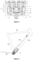
Figure 1 is a schematic sectional view showing a centrally mounted driving mechanism for a power-assisted bicycle according to a first preferred embodiment of the present application; -
Figure 2 is a schematic structural view showing the connection between a planetary gear output bracket and a bevel gear support in the first preferred embodiment; -
Figure 3 is a schematic view showing an assembly structure ofFigure 2 ; -
Figure 4 is a schematic sectional view showing a centrally mounted driving mechanism for a power-assisted bicycle according to a second not claimed embodiment of the present application; -
Figure 5 is a schematic structural view showing the connection between a planetary gear output bracket and a bevel gear support in the second not claimed embodiment; and -
Figure 6 is a schematic view showing the structure of a frame of a power-assisted bicycle employing the centrally mounted driving mechanism for the power-assisted bicycle according to the present application. - The technical solutions in the embodiments of the present application will be described clearly and completely hereinafter in conjunction with the drawings in the embodiments of the present application.
- An object of the present application is to provide a centrally mounted driving mechanism for a power-assisted bicycle, and the centrally mounted driving mechanism has the advantages of having a small axial length, compact structure and small size. Another object of the present application is to provide a power-assisted bicycle including the centrally mounted driving mechanism. The centrally mounted driving mechanism is mounted in a frame pipe of the power-assisted bicycle, which reserves more space to accommodate a battery with larger capacity, so that the power-assisted bicycle has greater output power and a longer battery life.
- In order to make those skilled in the art better understand technical solutions of the present application, the present application is further illustrated in detail with reference to the accompanying drawings and specific embodiments hereinafter.
- It should be noted that, the orientation terms such as "upper, lower, left, right" in the description hereinafter are defined based on the drawings of the specification.
- As shown in
Figure 1 , a centrally mounted driving mechanism for a power-assisted bicycle is provided according to a first preferred embodiment of the present application. The centrally mounted driving mechanism includes amotor 2, a planetary gear mechanism, aclutch 6, a bevel gear mechanism, acrankset support 11 and acrankset 13. The bevel gear mechanism includes abevel gear support 8, a bevelgear driving end 9 and a bevel gear drivenend 10. An output shaft of themotor 2 is in transmission connection with the planetary gear mechanism, and themotor 2 is configured to provide a driving force. The planetary gear mechanism includes aplanetary gear 4 and a planetarygear output bracket 5. Theplanetary gear 4 is in transmission connection with the output shaft of themotor 2, the planetarygear output bracket 5 is inserted into thebevel gear support 8, and theclutch 6 is mounted between the planetarygear output bracket 5 and thebevel gear support 8. Thebevel gear support 8 is connected to the bevelgear driving end 9, and the bevelgear driving end 9 is connected with the bevel gear drivenend 10 configured for driving thecrankset support 11 to rotate. The bevel gear drivenend 10 is fixedly connected to or integrally formed with thecrankset support 11. Thus, an output end of the planetary gear is connected to the bevel gear mechanism for speed reduction, and finally, the bevel gear mechanism is connected to thecrankset support 11 to drive thecrankset 13 to rotate, so as to assist the power-assisted bicycle. - Specifically, referring to
Figures 2 and3 , the planetarygear output bracket 5 has ashaft portion 51, and thebevel gear support 8 has a secondannular protrusion 82, and the secondannular protrusion 82 surrounds theshaft portion 51. Theclutch 6 is arranged between an inner wall of the secondannular protrusion 82 and theshaft portion 51, and theclutch 6 is fitted with and connected to thebevel gear support 8 and the planetarygear output bracket 5, to realize the connection and separation between thebevel gear support 8 and the planetarygear output bracket 5. Thus, in a case that themotor 2 is powered off or does not start, the transmission connection between thecrankset 13 and themotor 2 can be disconnected byclutch 6, thus avoiding the rotation of themotor 2 when a user pedals the power-assisted bicycle. A needle roller clutch is preferably employed, and the arrangement of the clutch 6 may refer to the conventional technology. - Further, the
bevel gear support 8 is provided with a firstannular protrusion 81 located at an inner side of the secondannular protrusion 82. The firstannular protrusion 81 is coaxial with the secondannular protrusion 82, and a preset gap is provided between the secondannular protrusion 82 and the firstannular protrusion 81. Agroove 52 is provided at an end of theshaft portion 51 away from theplanetary gear 4, and thegroove 52 is arranged to be coaxial with the planetarygear output bracket 5. The firstannular protrusion 81 is inserted into thegroove 52, and a gap is reserved between the firstannular protrusion 81 and an inner wall of thegroove 52. The bevelgear driving end 9 is connected with an inner wall of the firstannular protrusion 81. By inserting the firstannular protrusion 81 into thegroove 52, a connected length of the planetarygear output bracket 5 and the bevelgear driving end 9 is reduced, the connection is strong, and the axial length of the centrally mounted driving mechanism can be further reduced. - In addition, an outer wall of the second
annular protrusion 82 is connected with asupport assembly 7 configured for supporting and positioning thebevel gear support 8. Ahousing 1 is provided outside the planetarygear output bracket 5 for protection, and a bearingassembly 12 configured for supporting and positioning thecrankset support 11 is provided between thehousing 1 and thecrankset support 11. Certainly, according to practical requirements, thesupport assembly 7 and the bearingassembly 12 may be arranged as two bearings arranged side by side or as a double row bearing. - The
support assembly 7 is arranged around the outer wall of the secondannular protrusion 82, and thesupport assembly 7 is connected with thehousing 1, so that thebevel gear support 8 and the planetarygear output bracket 5 are supported at the same time. This arrangement not only simplify the structure, reduce the number of positioning members, but also reduce the axial length of the centrally mounted driving mechanism, thus an overall structure of the centrally mounted driving mechanism is more compact, and the size is smaller. - Further, the first
annular protrusion 81 is fixedly connected with the bevelgear driving end 9, the bevelgear driving end 9 is configured to transmit motion and power of thebevel gear support 8, and an outer wall of the bevelgear driving end 9 may be in interference fit with the inner wall of the firstannular protrusion 81. Certainly, according to practical requirements, in the premise that a torque transmission function is satisfied, the bevelgear driving end 9 may be welded to thebevel gear support 8. Certainly, the bevelgear driving end 9 may also be integrally formed with thebevel gear support 8, which may reduce a length for interference fit required by interference press-fit or even avoid the interference press-fit, thus further reducing the axial length of the centrally mounted driving mechanism. - In conventional technology, the
bevel gear support 8 protrudes downward and is connected with the bevelgear driving end 9, and the interference fit with a certain theoretical length will be designed to ensure the strength and reliability of the connection. In other words, the length of the bevelgear driving end 9 and thebevel gear support 8 in close fit is greater than a certain theoretical value, in this case, the bevel gear is closer to a lower end of the motor in the axial direction, which leads to a larger size in the axial direction, and a separate positioning member is required for positioning the bevelgear driving end 9. However, according to the present application, a portion where the bevelgear driving end 9 and the firstannular protrusion 81 are fitted with each other is located in thegroove 52, and an outer wall of thebevel gear support 8 surrounds theshaft portion 51 of the planetarygear output bracket 5, so that a portion where thebevel gear support 8 is in interference fit with the bevelgear driving end 9 overlaps with the planetarygear output bracket 5 in the axial direction of themotor 2, which reduces the axial dimension of the overall structure. In addition, only the outer wall of thebevel gear support 8 is required to be provided with a positioning mechanism, and the structure for positioning is simple. - In order to optimize the above embodiment, a
gasket 3 is provided on an upper end face of theplanetary gear 4, and thegasket 3 is configured for preventing theplanetary gear 4 from being worn and preventing theplanetary gear 4 from playing in the axial direction thereof. Thegasket 3 may be an annular-shaped gasket, and a central hole of the annular-shaped gasket is configured to allow the output shaft of themotor 2 to pass through. - In the conventional technology, a holder of the conventional
planetary gear 4 includes an upper holder and a lower holder, an end of a positioning shaft of theplanetary gear 4 is in clearance fit with the upper holder, and another end of the positioning shaft of theplanetary gear 4 is in interference fit with the lower holder. However, according to the present application, thegasket 3 is arranged between thehousing 1 and theplanetary gear 4, so that an upper end of theplanetary gear 4 is not required to be provided with a holder, which further reduces the axial length of the whole structure. Moreover, since the upper holder is not provided, the positioning shaft of theplanetary gear 4 is not required to be in clearance fit with the upper holder, which can avoid frictions, reduce losses and improve transmission efficiency. - As shown in
Figure 4 , a centrally mounted driving mechanism for a power-assisted bicycle is provided according to a second not claimed embodiment of the present application. The difference between the second not claimed embodiment and the first preferred embodiment lies in a planetarygear output bracket 5A, a clutch 6A, asupport assembly 7A, abevel gear support 8A and a bevelgear driving end 9A. The planetarygear output bracket 5A is connected with the clutch 6A, the clutch 6A is connected with thebevel gear support 8A located outside the clutch 6A, thebevel gear support 8A is connected with the bevelgear driving end 9A, and thesupport assembly 7A surrounds thebevel gear support 8A. - Specifically, referring to
Figure 5 , in the second not claimed embodiment, thebevel gear support 8A is cup-shaped. Thebevel gear support 8A has a bottom 81A and a secondannular protrusion 82A. A through hole is provided at a central portion of the bottom 81A. The bevelgear driving end 9A is fixedly connected with thebevel gear support 8A through the through hole by means of interference fit, welding or threaded connection. The planetarygear output bracket 5A has ashaft portion 51A, and theshaft portion 5A is inserted into the secondannular protrusion 82A. The clutch 6A is arranged between theshaft portion 51A and the secondannular protrusion 82A, and the clutch 6A is fitted to and connected with theshaft portion 51A and the secondannular protrusion 82A, to realize the connection and separation of thebevel gear support 8A and the planetarygear output bracket 5A. In order to ensure that the axial length of the whole structure will not be increased, a wedge-type clutch is preferably employed. - It should be noted that, a tail end of the bevel
gear driving end 9A is provided with a transition structure to facilitate screwed installation, but the tail end of the bevelgear driving end 9A does not form strong connection with the planetarygear output bracket 5A. In order to further reduce the axial length, the tail end of the bevelgear driving end 9A is arranged to run through the bottom 81A, and agroove 52A is provided at a corresponding position of theshaft portion 51A. The tail end of the bevelgear driving end 9A extends into thegroove 52A, and a gap is reserved between the tail end of the bevelgear driving end 9A and an inner wall of thegroove 52A, so as to prevent interference during rotation. - A sliding
bearing 61A is provided at each of two ends of the clutch 6A, and the slidingbearing 61A is supported between theshaft portion 51A and the secondannular protrusion 82A. The position-limiting of the planetarygear output bracket 5A is realized through the two slidingbearings 61A, thereby avoiding deflection. - The
support assembly 7A includes afirst bearing 71A and asecond bearing 72A arranged side by side. Thefirst bearing 71A and thesecond bearing 72A are respectively arranged around a side portion of the secondannular protrusion 82A, thefirst bearing 71A and thesecond bearing 72A are arranged to be spaced apart from each other, thefirst bearing 71A is arranged at an end of the side portion close to theplanetary gear 4, and thesecond bearing 72A is arranged at another end of the side portion away from theplanetary gear 4. With the arrangement that thefirst bearing 71A and thesecond bearing 72A are arranged to be spaced apart from each other, a distance between central support surfaces of thefirst bearing 71A and thesecond bearing 72A may be increased, which extends a support arm, thus providing more stable support for the bevelgear driving end 9A. Specifically, aspacer 73A is arranged between the two bearings to realize separation. Thespacer 73A may be a gasket surrounding thebevel gear support 8A or a side protrusion integrally formed with thebevel gear support 8A. - Further, an inner diameter of the
first bearing 71A is the same as that of thesecond bearing 72A, and an outer diameter of thefirst bearing 71A is less than that of thesecond bearing 72A. That is, a size of thesecond bearing 72A is greater than that of thefirst bearing 71A. Thesupport assembly 7A forms a cantilever support structure for the bevelgear driving end 9A. Compared with thefirst bearing 71A, thesecond bearing 72A is closer to the bevelgear driving end 9A, and thesecond bearing 72A provides a stronger supporting force. With the arrangement that the size of thesecond bearing 72A is greater than that of thefirst bearing 71A, the distance between the central support surfaces of thefirst bearing 71A and thesecond bearing 72A may be further increased, which extends the support arm, and thus the support for the bevelgear driving end 9A is more stable. - A power-assisted bicycle according to the present application includes the centrally mounted driving mechanism described in the preferred embodiments. As shown in
Figure 6 , a frame of the power-assisted bicycle includes atop tube 20, adown tube 30, aseat tube 40, achain stay 50 and abattery pack 60. Thetop tube 20, thedown tube 30 and theseat tube 40 are sequentially connected end to end to form a triangle structure, and thechain stay 50 is connected with thedown tube 30 to connect a rear wheel. The centrally mounted driving mechanism is mounted in thedown tube 30, and the centrally mounted driving mechanism is located at an end of thedown tube 30 connected with theseat tube 40. Thebattery pack 60 is also mounted in thedown tube 30. Since the axial length of the centrally mounted driving mechanism is reduced, a remaining space in thedown tube 30 is larger, so that more batteries may be accommodated in thedown tube 30, and thus improving the battery life of the power-assisted bicycle. Other parts of the power-assisted bicycle may refer to the conventional technology, which are not described herein.
Claims (7)
- A centrally mounted driving mechanism applicable to a power-assisted bicycle, comprising:a housing (1);a motor (2) configured for providing a driving force;a planetary gear mechanism in transmission connection with a motor output shaft;a bevel gear driving end (9, 9A);a bevel gear driven end (10) engaged with the bevel gear driving end (9, 9A), wherein the bevel gear driven end (10) is connected with a crankset (13), and the planetary gear mechanism comprises a planetary gear (4) and a planetary gear output bracket (5, 5A); and whereinthe centrally mounted driving mechanism further comprises a bevel gear support (8, 8A) sleeved outside the planetary gear output bracket (5, 5A), a clutch (6) is provided between the planetary gear output bracket (5, 5A) and the bevel gear support (8, 8A), and the planetary gear output bracket (5, 5A) is in transmission connection with the bevel gear support (8, 8A) through the clutch (6);the bevel gear driving end (9, 9A) is coaxially and fixedly connected with the bevel gear support (8, 8A), and a support assembly (7, 7A) is provided outside the bevel gear support (8, 8A), and the support assembly (7) is configured to support the planetary gear output bracket (5, 5A) and the bevel gear driving end (9, 9A);the planetary gear output bracket (5, 5A) has a shaft portion (51, 51A), the bevel gear support (8, 8A) has a second annular protrusion (82, 82A), and the second annular protrusion (82, 82A) is configured to surround the shaft portion (51, 51A);the clutch (6, 6A) is arranged between the second annular protrusion (82, 82A) and the planetary gear output bracket (5, 5A), and the clutch (6, 6A) is fitted with and connected to the bevel gear support (8, 8A) and the planetary gear output bracket (5, 5A), to realize connection and separation of the bevel gear support (8, 8A) and the planetary gear output bracket (5, 5A); andthe support assembly (7, 7A) is arranged outside the second annular protrusion (82, 82A); characterized in that,the bevel gear support (8) is provided with a first annular protrusion (81) located at an inner side of the second annular protrusion (82), the bevel gear driving end (9) is connected to an inner wall of the first annular protrusion (81); and a groove (52) is provided at an end of the shaft portion (51) away from the planetary gear (4), the first annular protrusion (81) is inserted into the groove (52), and a gap is provided between the first annular protrusion (81) and an inner wall of the groove (52).
- The centrally mounted driving mechanism according to claim 1, wherein a sliding bearing (61A) is provided at each of two ends of the clutch (6A), and the sliding bearing (61A) is supported between the shaft portion (51A) and the second annular protrusion (82A).
- The centrally mounted driving mechanism according to claim 1, wherein the support assembly (7A) comprises a first bearing (71A) and a second bearing (72A) arranged to be spaced apart from each other, and the first bearing (71A) and the second bearing (72A) are respectively arranged around a side portion of the second annular protrusion (82A).
- The centrally mounted driving mechanism according to claim 3, wherein the first bearing (71A) is arranged at an end of the side portion close to the planetary gear (4), and the second bearing (72A) is arranged at another end of the side portion away from the planetary gear (4), an outer diameter of the first bearing (71A) is less than that of the second bearing (72A).
- The centrally mounted driving mechanism according to claim 1, further comprising a crankset support (11), wherein the bevel gear driven end (10) is connected to the crankset (13) through the crankset support (11); and a bearing assembly configured for supporting and positioning the crankset support (11) is provided between the crankset support (11) and the housing (1).
- The centrally mounted driving mechanism according to claim 1, wherein a gasket (3) is provided on an upper end face of the planetary gear (4), and the gasket (3) is configured for preventing the planetary gear (4) from being worn and preventing the planetary gear (4) from playing in an axial direction thereof.
- A power-assisted bicycle, comprisingthe centrally mounted driving mechanism according to any one of claims 1 to 6;a down tube (20); anda battery pack (60), wherein the centrally mounted driving mechanism and the battery pack (60) are mounted in the down tube (20).
Applications Claiming Priority (2)
| Application Number | Priority Date | Filing Date | Title |
|---|---|---|---|
| CN201911134539 | 2019-11-19 | ||
| CN202010304310.8A CN112896409B (en) | 2019-11-19 | 2020-04-17 | A mid-mounted driving mechanism for power-assisted bicycle and power-assisted bicycle |
Publications (3)
| Publication Number | Publication Date |
|---|---|
| EP3825218A1 EP3825218A1 (en) | 2021-05-26 |
| EP3825218B1 true EP3825218B1 (en) | 2025-06-25 |
| EP3825218C0 EP3825218C0 (en) | 2025-06-25 |
Family
ID=73455578
Family Applications (1)
| Application Number | Title | Priority Date | Filing Date |
|---|---|---|---|
| EP20208011.5A Active EP3825218B1 (en) | 2019-11-19 | 2020-11-17 | Centrally mounted driving mechanism for power-assisted bicycle and power-assisted bicycle |
Country Status (3)
| Country | Link |
|---|---|
| US (1) | US12403982B2 (en) |
| EP (1) | EP3825218B1 (en) |
| WO (1) | WO2021098500A1 (en) |
Families Citing this family (1)
| Publication number | Priority date | Publication date | Assignee | Title |
|---|---|---|---|---|
| DE102024128279A1 (en) * | 2024-09-30 | 2026-04-02 | Porsche Ebike Performance Gmbh | Drive device for an electric bicycle and assembly for a drive device |
Citations (1)
| Publication number | Priority date | Publication date | Assignee | Title |
|---|---|---|---|---|
| US20190111998A1 (en) * | 2017-10-13 | 2019-04-18 | Shimano Inc. | Bicycle drive unit |
Family Cites Families (15)
| Publication number | Priority date | Publication date | Assignee | Title |
|---|---|---|---|---|
| JP2634121B2 (en) * | 1992-03-06 | 1997-07-23 | ヤマハ発動機株式会社 | Bicycle with electric motor and motor control method therefor |
| EP0820925A1 (en) * | 1996-07-22 | 1998-01-28 | Merida Industry Co., Ltd. | Electrical drive for a bicycle |
| US6554730B1 (en) * | 1997-01-29 | 2003-04-29 | Nsk Ltd. | Auxiliary device for bicycle with traction roller type gear |
| DE29911858U1 (en) | 1999-07-08 | 1999-10-07 | Lin, Chun San, Tachia Town, Taichung | Drive device for an electric bicycle |
| EP1070660A1 (en) * | 1999-07-22 | 2001-01-24 | Merida Industry Co., Ltd. | Electric drive for a bicycle |
| JP5818814B2 (en) * | 2010-01-22 | 2015-11-18 | フォスター・アセッツ・コーポレーション | Motor with built-in torque sensor |
| CN205327312U (en) * | 2015-12-30 | 2016-06-22 | 天津迪思科博科技发展有限公司 | Put motor among electric bicycle with trigger mechanism brakes |
| CN105449921B (en) * | 2015-12-30 | 2017-10-27 | 天津迪思科博科技发展有限公司 | Concealed type built-in motor and the electric bicycle for installing concealed type built-in motor |
| CN206691312U (en) * | 2016-09-07 | 2017-12-01 | 新安乃达驱动技术(上海)股份有限公司 | Electric bicycle and wherein put drive system |
| US10137959B2 (en) * | 2016-10-26 | 2018-11-27 | Chun-Hsiang Liu | Electric bicycle drive assembly with torque detection |
| TWI635022B (en) * | 2017-03-30 | 2018-09-11 | 黃永松 | Clutch bicycle electric drive |
| JP6787866B2 (en) * | 2017-10-13 | 2020-11-18 | 株式会社シマノ | Bicycle components |
| CN208085921U (en) * | 2017-12-29 | 2018-11-13 | 门德君 | Concealed bicycle power-assisted accessory and composition bicycle |
| JP7219013B2 (en) * | 2018-04-06 | 2023-02-07 | 株式会社シマノ | Components for human-powered vehicles |
| CN110282067A (en) * | 2019-08-12 | 2019-09-27 | 苏州万佳电器有限公司 | Driving mechanism is set in a kind of and with the moped for setting driving mechanism in this |
-
2020
- 2020-11-03 US US17/776,526 patent/US12403982B2/en active Active
- 2020-11-03 WO PCT/CN2020/126022 patent/WO2021098500A1/en not_active Ceased
- 2020-11-17 EP EP20208011.5A patent/EP3825218B1/en active Active
Patent Citations (1)
| Publication number | Priority date | Publication date | Assignee | Title |
|---|---|---|---|---|
| US20190111998A1 (en) * | 2017-10-13 | 2019-04-18 | Shimano Inc. | Bicycle drive unit |
Also Published As
| Publication number | Publication date |
|---|---|
| EP3825218A1 (en) | 2021-05-26 |
| US12403982B2 (en) | 2025-09-02 |
| US20220379996A1 (en) | 2022-12-01 |
| WO2021098500A1 (en) | 2021-05-27 |
| EP3825218C0 (en) | 2025-06-25 |
Similar Documents
| Publication | Publication Date | Title |
|---|---|---|
| US10000255B2 (en) | Bicycle drive unit and bicycle equipped with the drive unit | |
| US10661858B2 (en) | Electric-motor-assisted bicycle | |
| KR20190022743A (en) | Bicycle Mid Motor and Electric Assisted Bicycle | |
| CN217216272U (en) | Drive device and electric vehicle | |
| CN105083463A (en) | Bicycle drive unit | |
| CN215398893U (en) | Gear type automobile wire control electric power steering gear | |
| EP4393807A1 (en) | Hub assembly and bicycle | |
| EP3825218A1 (en) | Centrally mounted driving mechanism for power-assisted bicycle and power-assisted bicycle | |
| CN212766630U (en) | Middle driving mechanism of power-assisted bicycle | |
| CN211663398U (en) | Middle-mounted driving device and bicycle with same | |
| CN112896409B (en) | A mid-mounted driving mechanism for power-assisted bicycle and power-assisted bicycle | |
| CN213064584U (en) | Double-shaft synchronous output permanent magnet direct current motor | |
| CN212766631U (en) | A put actuating mechanism and moped in for moped | |
| CN220098451U (en) | Double-motor coaxial integrated heavy-load vertical power wheel and unmanned forklift using same | |
| CN220857821U (en) | Middle motor and electric bicycle | |
| CN216762053U (en) | Compact mid-motor adopting two-stage gear reduction mechanism | |
| EP4249360B1 (en) | Electric assistant motor module and reducing structure | |
| WO2023236046A1 (en) | Power-assisted drive assembly | |
| CN217216273U (en) | Drive device and electric vehicle | |
| CN214743073U (en) | Wheel-side speed reducing mechanism for front-wheel double-drive forklift | |
| CN214823908U (en) | Mid-mounted motor transmission mechanism, electric bicycle drive system and electric bicycle | |
| CN117318379A (en) | Mid-mounted motor of electric bicycle and its working method | |
| CN212785045U (en) | Variable speed motor | |
| CN113525583B (en) | A mid-mounted driving mechanism for a power-assisted bicycle | |
| CN224184101U (en) | Carrier and drive assembly for quick switching of flashlight thereof |
Legal Events
| Date | Code | Title | Description |
|---|---|---|---|
| PUAI | Public reference made under article 153(3) epc to a published international application that has entered the european phase |
Free format text: ORIGINAL CODE: 0009012 |
|
| STAA | Information on the status of an ep patent application or granted ep patent |
Free format text: STATUS: THE APPLICATION HAS BEEN PUBLISHED |
|
| AK | Designated contracting states |
Kind code of ref document: A1 Designated state(s): AL AT BE BG CH CY CZ DE DK EE ES FI FR GB GR HR HU IE IS IT LI LT LU LV MC MK MT NL NO PL PT RO RS SE SI SK SM TR |
|
| STAA | Information on the status of an ep patent application or granted ep patent |
Free format text: STATUS: REQUEST FOR EXAMINATION WAS MADE |
|
| 17P | Request for examination filed |
Effective date: 20211125 |
|
| RBV | Designated contracting states (corrected) |
Designated state(s): AL AT BE BG CH CY CZ DE DK EE ES FI FR GB GR HR HU IE IS IT LI LT LU LV MC MK MT NL NO PL PT RO RS SE SI SK SM TR |
|
| STAA | Information on the status of an ep patent application or granted ep patent |
Free format text: STATUS: EXAMINATION IS IN PROGRESS |
|
| 17Q | First examination report despatched |
Effective date: 20230317 |
|
| GRAP | Despatch of communication of intention to grant a patent |
Free format text: ORIGINAL CODE: EPIDOSNIGR1 |
|
| STAA | Information on the status of an ep patent application or granted ep patent |
Free format text: STATUS: GRANT OF PATENT IS INTENDED |
|
| INTG | Intention to grant announced |
Effective date: 20250117 |
|
| GRAS | Grant fee paid |
Free format text: ORIGINAL CODE: EPIDOSNIGR3 |
|
| GRAA | (expected) grant |
Free format text: ORIGINAL CODE: 0009210 |
|
| STAA | Information on the status of an ep patent application or granted ep patent |
Free format text: STATUS: THE PATENT HAS BEEN GRANTED |
|
| AK | Designated contracting states |
Kind code of ref document: B1 Designated state(s): AL AT BE BG CH CY CZ DE DK EE ES FI FR GB GR HR HU IE IS IT LI LT LU LV MC MK MT NL NO PL PT RO RS SE SI SK SM TR |
|
| REG | Reference to a national code |
Ref country code: GB Ref legal event code: FG4D |
|
| REG | Reference to a national code |
Ref country code: CH Ref legal event code: EP |
|
| REG | Reference to a national code |
Ref country code: DE Ref legal event code: R096 Ref document number: 602020053226 Country of ref document: DE |
|
| REG | Reference to a national code |
Ref country code: CH Ref legal event code: EP |
|
| REG | Reference to a national code |
Ref country code: IE Ref legal event code: FG4D |
|
| U01 | Request for unitary effect filed |
Effective date: 20250716 |
|
| U07 | Unitary effect registered |
Designated state(s): AT BE BG DE DK EE FI FR IT LT LU LV MT NL PT RO SE SI Effective date: 20250723 |
|
| PG25 | Lapsed in a contracting state [announced via postgrant information from national office to epo] |
Ref country code: NO Free format text: LAPSE BECAUSE OF FAILURE TO SUBMIT A TRANSLATION OF THE DESCRIPTION OR TO PAY THE FEE WITHIN THE PRESCRIBED TIME-LIMIT Effective date: 20250925 Ref country code: GR Free format text: LAPSE BECAUSE OF FAILURE TO SUBMIT A TRANSLATION OF THE DESCRIPTION OR TO PAY THE FEE WITHIN THE PRESCRIBED TIME-LIMIT Effective date: 20250926 |
|
| PG25 | Lapsed in a contracting state [announced via postgrant information from national office to epo] |
Ref country code: HR Free format text: LAPSE BECAUSE OF FAILURE TO SUBMIT A TRANSLATION OF THE DESCRIPTION OR TO PAY THE FEE WITHIN THE PRESCRIBED TIME-LIMIT Effective date: 20250625 |
|
| PG25 | Lapsed in a contracting state [announced via postgrant information from national office to epo] |
Ref country code: RS Free format text: LAPSE BECAUSE OF FAILURE TO SUBMIT A TRANSLATION OF THE DESCRIPTION OR TO PAY THE FEE WITHIN THE PRESCRIBED TIME-LIMIT Effective date: 20250925 |
|
| REG | Reference to a national code |
Ref country code: CH Ref legal event code: U11 Free format text: ST27 STATUS EVENT CODE: U-0-0-U10-U11 (AS PROVIDED BY THE NATIONAL OFFICE) Effective date: 20251211 |
|
| U20 | Renewal fee for the european patent with unitary effect paid |
Year of fee payment: 6 Effective date: 20251127 |
|
| PG25 | Lapsed in a contracting state [announced via postgrant information from national office to epo] |
Ref country code: IS Free format text: LAPSE BECAUSE OF FAILURE TO SUBMIT A TRANSLATION OF THE DESCRIPTION OR TO PAY THE FEE WITHIN THE PRESCRIBED TIME-LIMIT Effective date: 20251025 |
|
| PGFP | Annual fee paid to national office [announced via postgrant information from national office to epo] |
Ref country code: GB Payment date: 20251127 Year of fee payment: 6 |
|
| PG25 | Lapsed in a contracting state [announced via postgrant information from national office to epo] |
Ref country code: SM Free format text: LAPSE BECAUSE OF FAILURE TO SUBMIT A TRANSLATION OF THE DESCRIPTION OR TO PAY THE FEE WITHIN THE PRESCRIBED TIME-LIMIT Effective date: 20250625 |
|
| PGFP | Annual fee paid to national office [announced via postgrant information from national office to epo] |
Ref country code: CH Payment date: 20251211 Year of fee payment: 6 |
|
| PG25 | Lapsed in a contracting state [announced via postgrant information from national office to epo] |
Ref country code: CZ Free format text: LAPSE BECAUSE OF FAILURE TO SUBMIT A TRANSLATION OF THE DESCRIPTION OR TO PAY THE FEE WITHIN THE PRESCRIBED TIME-LIMIT Effective date: 20250625 |
|
| PG25 | Lapsed in a contracting state [announced via postgrant information from national office to epo] |
Ref country code: PL Free format text: LAPSE BECAUSE OF FAILURE TO SUBMIT A TRANSLATION OF THE DESCRIPTION OR TO PAY THE FEE WITHIN THE PRESCRIBED TIME-LIMIT Effective date: 20250625 |
|
| PG25 | Lapsed in a contracting state [announced via postgrant information from national office to epo] |
Ref country code: SK Free format text: LAPSE BECAUSE OF FAILURE TO SUBMIT A TRANSLATION OF THE DESCRIPTION OR TO PAY THE FEE WITHIN THE PRESCRIBED TIME-LIMIT Effective date: 20250625 |
|
| PG25 | Lapsed in a contracting state [announced via postgrant information from national office to epo] |
Ref country code: ES Free format text: LAPSE BECAUSE OF FAILURE TO SUBMIT A TRANSLATION OF THE DESCRIPTION OR TO PAY THE FEE WITHIN THE PRESCRIBED TIME-LIMIT Effective date: 20250625 |
|
| PLBE | No opposition filed within time limit |
Free format text: ORIGINAL CODE: 0009261 |
|
| STAA | Information on the status of an ep patent application or granted ep patent |
Free format text: STATUS: NO OPPOSITION FILED WITHIN TIME LIMIT |
|
| REG | Reference to a national code |
Ref country code: CH Ref legal event code: L10 Free format text: ST27 STATUS EVENT CODE: U-0-0-L10-L00 (AS PROVIDED BY THE NATIONAL OFFICE) Effective date: 20260507 |