EP3825094A1 - Slot die for manufacturing rechargeable battery electrode - Google Patents
Slot die for manufacturing rechargeable battery electrode Download PDFInfo
- Publication number
- EP3825094A1 EP3825094A1 EP20209037.9A EP20209037A EP3825094A1 EP 3825094 A1 EP3825094 A1 EP 3825094A1 EP 20209037 A EP20209037 A EP 20209037A EP 3825094 A1 EP3825094 A1 EP 3825094A1
- Authority
- EP
- European Patent Office
- Prior art keywords
- width
- slot
- block
- discharging direction
- discharging
- Prior art date
- Legal status (The legal status is an assumption and is not a legal conclusion. Google has not performed a legal analysis and makes no representation as to the accuracy of the status listed.)
- Granted
Links
Images







Classifications
-
- B—PERFORMING OPERATIONS; TRANSPORTING
- B05—SPRAYING OR ATOMISING IN GENERAL; APPLYING FLUENT MATERIALS TO SURFACES, IN GENERAL
- B05C—APPARATUS FOR APPLYING FLUENT MATERIALS TO SURFACES, IN GENERAL
- B05C5/00—Apparatus in which liquid or other fluent material is projected, poured or allowed to flow on to the surface of the work
- B05C5/02—Apparatus in which liquid or other fluent material is projected, poured or allowed to flow on to the surface of the work the liquid or other fluent material being discharged through an outlet orifice by pressure, e.g. from an outlet device in contact or almost in contact, with the work
- B05C5/0254—Coating heads with slot-shaped outlet
- B05C5/0262—Coating heads with slot-shaped outlet adjustable in width, i.e. having lips movable relative to each other in order to modify the slot width, e.g. to close it
-
- B—PERFORMING OPERATIONS; TRANSPORTING
- B05—SPRAYING OR ATOMISING IN GENERAL; APPLYING FLUENT MATERIALS TO SURFACES, IN GENERAL
- B05C—APPARATUS FOR APPLYING FLUENT MATERIALS TO SURFACES, IN GENERAL
- B05C5/00—Apparatus in which liquid or other fluent material is projected, poured or allowed to flow on to the surface of the work
- B05C5/02—Apparatus in which liquid or other fluent material is projected, poured or allowed to flow on to the surface of the work the liquid or other fluent material being discharged through an outlet orifice by pressure, e.g. from an outlet device in contact or almost in contact, with the work
- B05C5/0254—Coating heads with slot-shaped outlet
-
- B—PERFORMING OPERATIONS; TRANSPORTING
- B05—SPRAYING OR ATOMISING IN GENERAL; APPLYING FLUENT MATERIALS TO SURFACES, IN GENERAL
- B05C—APPARATUS FOR APPLYING FLUENT MATERIALS TO SURFACES, IN GENERAL
- B05C5/00—Apparatus in which liquid or other fluent material is projected, poured or allowed to flow on to the surface of the work
- B05C5/02—Apparatus in which liquid or other fluent material is projected, poured or allowed to flow on to the surface of the work the liquid or other fluent material being discharged through an outlet orifice by pressure, e.g. from an outlet device in contact or almost in contact, with the work
- B05C5/0254—Coating heads with slot-shaped outlet
- B05C5/0266—Coating heads with slot-shaped outlet adjustable in length, e.g. for coating webs of different width
-
- B—PERFORMING OPERATIONS; TRANSPORTING
- B05—SPRAYING OR ATOMISING IN GENERAL; APPLYING FLUENT MATERIALS TO SURFACES, IN GENERAL
- B05D—PROCESSES FOR APPLYING FLUENT MATERIALS TO SURFACES, IN GENERAL
- B05D1/00—Processes for applying liquids or other fluent materials
- B05D1/36—Successively applying liquids or other fluent materials, e.g. without intermediate treatment
-
- B—PERFORMING OPERATIONS; TRANSPORTING
- B29—WORKING OF PLASTICS; WORKING OF SUBSTANCES IN A PLASTIC STATE IN GENERAL
- B29C—SHAPING OR JOINING OF PLASTICS; SHAPING OF MATERIAL IN A PLASTIC STATE, NOT OTHERWISE PROVIDED FOR; AFTER-TREATMENT OF THE SHAPED PRODUCTS, e.g. REPAIRING
- B29C48/00—Extrusion moulding, i.e. expressing the moulding material through a die or nozzle which imparts the desired form; Apparatus therefor
- B29C48/03—Extrusion moulding, i.e. expressing the moulding material through a die or nozzle which imparts the desired form; Apparatus therefor characterised by the shape of the extruded material at extrusion
- B29C48/07—Flat, e.g. panels
- B29C48/08—Flat, e.g. panels flexible, e.g. films
-
- B—PERFORMING OPERATIONS; TRANSPORTING
- B29—WORKING OF PLASTICS; WORKING OF SUBSTANCES IN A PLASTIC STATE IN GENERAL
- B29C—SHAPING OR JOINING OF PLASTICS; SHAPING OF MATERIAL IN A PLASTIC STATE, NOT OTHERWISE PROVIDED FOR; AFTER-TREATMENT OF THE SHAPED PRODUCTS, e.g. REPAIRING
- B29C48/00—Extrusion moulding, i.e. expressing the moulding material through a die or nozzle which imparts the desired form; Apparatus therefor
- B29C48/25—Component parts, details or accessories; Auxiliary operations
- B29C48/30—Extrusion nozzles or dies
- B29C48/305—Extrusion nozzles or dies having a wide opening, e.g. for forming sheets
-
- H—ELECTRICITY
- H01—ELECTRIC ELEMENTS
- H01M—PROCESSES OR MEANS, e.g. BATTERIES, FOR THE DIRECT CONVERSION OF CHEMICAL ENERGY INTO ELECTRICAL ENERGY
- H01M4/00—Electrodes
- H01M4/02—Electrodes composed of, or comprising, active material
- H01M4/04—Processes of manufacture in general
- H01M4/0402—Methods of deposition of the material
-
- H—ELECTRICITY
- H01—ELECTRIC ELEMENTS
- H01M—PROCESSES OR MEANS, e.g. BATTERIES, FOR THE DIRECT CONVERSION OF CHEMICAL ENERGY INTO ELECTRICAL ENERGY
- H01M4/00—Electrodes
- H01M4/02—Electrodes composed of, or comprising, active material
- H01M4/04—Processes of manufacture in general
- H01M4/0402—Methods of deposition of the material
- H01M4/0404—Methods of deposition of the material by coating on electrode collectors
-
- H—ELECTRICITY
- H01—ELECTRIC ELEMENTS
- H01M—PROCESSES OR MEANS, e.g. BATTERIES, FOR THE DIRECT CONVERSION OF CHEMICAL ENERGY INTO ELECTRICAL ENERGY
- H01M4/00—Electrodes
- H01M4/02—Electrodes composed of, or comprising, active material
- H01M4/62—Selection of inactive substances as ingredients for active masses, e.g. binders, fillers
-
- B—PERFORMING OPERATIONS; TRANSPORTING
- B29—WORKING OF PLASTICS; WORKING OF SUBSTANCES IN A PLASTIC STATE IN GENERAL
- B29C—SHAPING OR JOINING OF PLASTICS; SHAPING OF MATERIAL IN A PLASTIC STATE, NOT OTHERWISE PROVIDED FOR; AFTER-TREATMENT OF THE SHAPED PRODUCTS, e.g. REPAIRING
- B29C48/00—Extrusion moulding, i.e. expressing the moulding material through a die or nozzle which imparts the desired form; Apparatus therefor
- B29C48/15—Extrusion moulding, i.e. expressing the moulding material through a die or nozzle which imparts the desired form; Apparatus therefor incorporating preformed parts or layers, e.g. extrusion moulding around inserts
- B29C48/154—Coating solid articles, i.e. non-hollow articles
- B29C48/155—Partial coating thereof
-
- B—PERFORMING OPERATIONS; TRANSPORTING
- B29—WORKING OF PLASTICS; WORKING OF SUBSTANCES IN A PLASTIC STATE IN GENERAL
- B29L—INDEXING SCHEME ASSOCIATED WITH SUBCLASS B29C, RELATING TO PARTICULAR ARTICLES
- B29L2031/00—Other particular articles
- B29L2031/34—Electrical apparatus, e.g. sparking plugs or parts thereof
- B29L2031/3468—Batteries, accumulators or fuel cells
-
- H—ELECTRICITY
- H01—ELECTRIC ELEMENTS
- H01M—PROCESSES OR MEANS, e.g. BATTERIES, FOR THE DIRECT CONVERSION OF CHEMICAL ENERGY INTO ELECTRICAL ENERGY
- H01M4/00—Electrodes
- H01M4/02—Electrodes composed of, or comprising, active material
- H01M2004/025—Electrodes composed of, or comprising, active material with shapes other than plane or cylindrical
-
- Y—GENERAL TAGGING OF NEW TECHNOLOGICAL DEVELOPMENTS; GENERAL TAGGING OF CROSS-SECTIONAL TECHNOLOGIES SPANNING OVER SEVERAL SECTIONS OF THE IPC; TECHNICAL SUBJECTS COVERED BY FORMER USPC CROSS-REFERENCE ART COLLECTIONS [XRACs] AND DIGESTS
- Y02—TECHNOLOGIES OR APPLICATIONS FOR MITIGATION OR ADAPTATION AGAINST CLIMATE CHANGE
- Y02E—REDUCTION OF GREENHOUSE GAS [GHG] EMISSIONS, RELATED TO ENERGY GENERATION, TRANSMISSION OR DISTRIBUTION
- Y02E60/00—Enabling technologies; Technologies with a potential or indirect contribution to GHG emissions mitigation
- Y02E60/10—Energy storage using batteries
Definitions
- the present invention relates to a slot die for manufacturing a rechargeable battery electrode. More particularly, the present invention relates to a slot die for manufacturing a rechargeable battery electrode including a shim member for controlling a discharging rate of an active material slurry coated on a substrate.
- a rechargeable battery repeats charging and discharging, differing from a primary cell.
- a small rechargeable battery is used for portable small electronic devices such as a mobile phone, a laptop computer, or a camcorder.
- a large capacity and high density rechargeable battery is used to store motor driving power or energy of hybrid vehicles and electric vehicles.
- the rechargeable battery includes an electrode assembly for charging and discharging a current, a case for receiving the electrode assembly and an electrolyte solution, a cap plate combined to an opening of the case, and an electrode end for drawing out the electrode assembly to an outside of the cap plate.
- the electrode assembly may be formed by disposing electrodes on respective sides of a separation film that is an electrical insulator, and spirally winding the separation films and the electrodes, stacking them, or mixing them.
- the separation film allows charging and discharging of the electrode assembly by separating the electrodes with different polarities and maintaining ion conductivity in the electrode assembly.
- the electrode is formed by coating an active material slurry on the substrate.
- a slot die is used when the electrode is manufactured by coating the active material slurry on the substrate.
- the slot die includes a lower block and an upper block for forming a chamber for supplying the active material slurry and setting a height of a slot for discharging the active material slurry, and a shim member installed therebetween and setting a width of a slot.
- the width of the slot set between respective ends of the shim member when a distribution of discharging rates of the active material slurry becomes non-uniform, a soaring phenomenon of the active material slurry is generated at edges of the respective ends of the substrate in a width direction, and a coating thickness of the active material slurry of the substrate in the width direction becomes non-uniform. In other words, the material slurry becomes higher at the edges relative to the rest of the substrate.
- the present invention has been made in an effort to provide a slot die for manufacturing a rechargeable battery electrode for providing a uniform coating thickness of an active material layer in terms of a width of a substrate by providing a uniform discharging rate distribution of an active material slurry in terms of a width of a slot.
- An exemplary embodiment of the present invention provides a slot die for manufacturing a rechargeable battery electrode, including: a first block; a second block facing the first block; and a shim member positioned between the first block and the second block, wherein the first block and the second block are combined to each other to form a slot for discharging an active material slurry
- the first block includes a chamber for receiving the active material slurry and forms a first side in a width direction and a discharging direction of the slot
- the second block faces the first side to form a second side in the width direction and the discharging direction of the slot
- the shim member includes end portions facing each other at respective ends of the first side and the second side and formed in a height direction of the slot, and the end portion includes a width adjuster protruding to a second reference point from a first reference point of the shim member in the width direction by a first adjusting width (Lw), inclined to a third reference point from the second reference point with a first angle ( ⁇ 1) with
- a width ratio (Lw/W) of the first adjusting width (Lw) vs. a width (W) of the slot may be greater than o and equal to or less than 0.1 (0 ⁇ Lw/W ⁇ 0.1).
- the width ratio (Lw/W) of the first adjusting width (Lw) vs. a width (W) of the slot may be equal to or greater than 0.02 and equal to or less than 0.06 (0.02 ⁇ Lw/W ⁇ 0.06).
- a length ratio (Ls/S) of the first adjusting length (Ls) vs. a length (S) of the slot in a discharging direction may be greater than 0 and equal to or less than 0.5 (0 ⁇ Ls/S ⁇ 0.5).
- the first angle ⁇ 1 may be greater than 0° and equal to or less than 30° (0° ⁇ ⁇ 1 ⁇ 30°).
- the width adjuster may include a width increased portion for gradually increasing a width of the slot from a minimum width of the slot in the discharging direction.
- the width adjuster may further include a width reduced portion connected to the width increased portion in the discharging direction and gradually reducing the width of the slot in the discharging direction.
- the width adjuster may be formed to be inclined with a second angle ⁇ 2 in an opposite direction to the first angle with respect to the discharging direction to a fourth reference point from the third reference point of the shim member.
- the second angle ⁇ 2 is greater than 0° and equal to or less than 15° (0° ⁇ ⁇ 2 ⁇ 15°).
- the width adjuster may further include a convex round portion further connected to the width reduced portion in the discharging direction, formed to be round at an end of the discharging direction, and increasing a width of the slot in the discharging direction.
- the width adjuster may include an additional width increased portion further connected to the width increased portion in the discharging direction and gradually additionally increasing a width of the slot in the discharging direction.
- the width adjuster may be formed to be inclined with a third angle ⁇ 3 in a direction of the first angle with respect to the discharging direction to a fifth reference point from the third reference point of the shim member.
- the third angle ⁇ 3 is greater than 0° and equal to or less than 25° (0° ⁇ ⁇ 3 ⁇ 25°).
- the width adjuster may further include a concave round portion further connected to the additional width increased portion in the discharging direction, formed to be round at the end of the discharging direction, and reducing the width of the slot in the discharging direction.
- the width adjuster may be formed in a straight line in the height direction so as to be vertically connected to the first side and the second side.
- the width adjuster may be formed to be concave round or convex round toward the slot so as to be connected to the first side and the second side in a round way.
- the slot die according to the exemplary embodiments of the present invention provides the uniform discharging rate distribution of the active material slurry to prevent the soaring shape of the active material slurry on the edges of the respective ends of the substrate in the width direction, in terms of the width of the slot set between the respective ends of the shim member. Therefore, the uniform coating thickness of the active material layer is obtained in the width direction of the substrate according to the exemplary embodiment.
- a slot die for manufacturing a rechargeable battery electrode comprising a first block, a second block facing the first block and a shim member positioned between the first block and the second block, the shim member having end portions spaced apart from one another to form a slot for discharging an active material slurry between the end portions and the facing surfaces of the first block and the second block, the first block includes a chamber for receiving the active material slurry, and each of the end portions includes a protrusion that reduces the width of the slot at the end opposite the end at which the active material slurry is discharged, wherein the angle of the protrusion is arranged to provide a substantially uniform discharge rate of the active material slurry across the width of the slot.
- FIG. 1 shows an exploded perspective view of a slot die for manufacturing a rechargeable battery electrode according to a first exemplary embodiment of the present invention
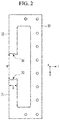
- FIG. 2 shows a top plan view of a shim member shown in FIG. 1
- FIG. 3 shows a cross-sectional view with respect to a line III-III of FIG. 1 .
- the slot die 1 for manufacturing a rechargeable battery electrode according to a first exemplary embodiment of the present invention includes a first block 10, a second block 20, and a shim member 30 installed therebetween.
- the first and second blocks 10 and 20 and the shim member 30 may be fastened by a fastening member 131 to form a slot die.
- the first block 10 includes a chamber 11 for temporarily storing a supplied active material slurry.
- a supply unit 12 is connected to a bottom of the first block 10 to supply the active material slurry to the chamber 11.
- the first and second blocks 10 and 20 combined to each other, in other words fixed together, form a slot 40 for discharging active material slurry.
- the slot 40 may be formed to be quadrangular in the x- and z-axis directions (refer to FIG. 9 ), or may be changed to be round in the x-axis direction according to the shape of the shim member 30.
- the first block 10 forms a first side 13 of the slot 40 in a width direction (x-axis direction) and a discharging direction (y-axis direction), which can also be seen as the bottom surface of the slot 40.
- the second block 20 forms a second side 23 of the slot 40 in the width direction (x-axis direction) and the discharging direction (y-axis direction), facing the first side 13, and can also be seen as the top surface of the slot.
- the shim member 30 is installed between the first and second blocks 10 and 20, and includes end portions 31 and 32 facing each other at the respective ends of the first side 13 and the second side 23 of the slot 40. These end portions 31, 32 form a third side 33 and a fourth side 34 of the slot 40 facing each other in the height direction (z-axis direction) and the discharging direction (y-axis direction).
- a thickness in the z-axis direction sets a height (H) of the slot 40
- a gap (a distance in the x-axis direction) between the end portions 31, 32 at the discharge side of the slot sets the width (W) of the slot 40
- the width of the third and fourth sides 33 and 34 in the discharging direction (y-axis direction) sets a length (S) of the slot 40.
- the slot die 1 temporarily stores the active material slurry supplied by the supply unit 12 in the chamber 11 and then discharges it through the slot 40, so the active material slurry is applied to the substrate (ES) proceeding to the front of the slot 40 to form an active material layer (AL) (refer to FIG. 12 and FIG. 14 ).
- FIG. 4 shows a top plan view of an end portion on one side of a shim member for setting a width of a slot shown in FIG. 2 .
- FIG. 4 will exemplify an end portion 32 on one side. Referring to FIG. 2 to FIG.
- the end portion 32 includes a width adjuster A1 protruding to a second reference point P2 from a first reference point P1 of the shim member 30 in the width direction (x-axis direction) by a first adjusting width (Lw), inclined to a third reference point P3 from the second reference point P2 with a first angle ⁇ 1 with respect to the discharging direction (y-axis direction), and formed in the discharging direction (y-axis direction) by a first adjusting length (Ls).
- a width adjuster A1 protruding to a second reference point P2 from a first reference point P1 of the shim member 30 in the width direction (x-axis direction) by a first adjusting width (Lw), inclined to a third reference point P3 from the second reference point P2 with a first angle ⁇ 1 with respect to the discharging direction (y-axis direction), and formed in the discharging direction (y-axis direction) by a first adjusting length (Ls).
- the width adjuster A1 is positioned on the facing third and fourth sides 33 and 34.
- the width adjuster A1 includes a width increased portion 341 for gradually increasing the width (W) of the slot 40 from a minimum width of the slot 40 with respect to the discharging direction (y-axis direction).
- the width increased portion 341 protrudes to the second reference point P2 from the first reference point P1 of the shim member 30 in the width direction (x-axis direction) by a first adjusting width (Lw), is inclined to the third reference point P3 from the second reference point P2 with the first angle ⁇ 1 with respect to the discharging direction (y-axis direction), and is formed in the discharging direction (y-axis direction) by the first adjusting length (Ls).
- a region L1 set with the first adjusting width (Lw) and the first adjusting length (Ls) at the end portion 32 of the shim member 30 increases the discharging rate of the active material slurry in a central portion of the slot 40 in the width direction (x-axis direction), and reduces the discharging rate of the active material slurry on the third and fourth sides 33 and 34 corresponding to the respective sides of the slot 40 in the width direction (x-axis direction). That is, the region L1 of the end portion 32 controls the discharging rate of the active material slurry throughout the width (W) of the slot 40 to be more uniform.
- a width ratio (Lw/W) of the first adjusting width (Lw) vs. width (W) of the slot 40 may be greater than 0 and equal to or less than 0.1 (0 ⁇ Lw/W ⁇ 0.1).
- the width ratio (Lw/W) is within the range (0 ⁇ Lw/W ⁇ 0.1)
- the discharging rate of the active material slurry appropriately falls, and the active material slurry may be uniformly coated on the substrate (ES).
- the width ratio (Lw/W) of the first adjusting width (Lw) vs. the width (W) of the slot 40 may be equal to or greater than 0.02 and equal to or less than 0.06 (0.02 ⁇ Lw/W ⁇ 0.06).
- the width ratio (Lw/W) may reduce the discharging rate of the active material slurry.
- the width increased portion 341 and the region L1 of the end portion 32 may control the discharging rate of the active material slurry throughout the width (W) of the slot 40 to be more uniform.
- a length ratio (Ls/S) of the first adjusting length (Ls) vs. the length (S) of the slot 40 in the discharging direction (y-axis direction) may be greater than 0 and equal to or less than 0.5 (0 ⁇ Ls/S ⁇ 0.5).
- the length ratio (Ls/S) is within the range (0 ⁇ Ls/S ⁇ 0.5)
- the reduced discharging rate of the active material slurry may be maintained for an appropriate time.
- the length ratio (Ls/S) of the first adjusting length (Ls) vs. the length (S) of the slot 40 in the discharging direction (y-axis direction) may be equal to or greater than 0.05 and equal to or less than 0.2 (0.05 ⁇ Ls/S ⁇ 0.2).
- the length ratio (Ls/S) may maintain the reduced discharging rate of the active material slurry for a predetermined time. Therefore, the width increased portion 341 and the region L1 of the end portion 32 may control the discharging rate of the active material slurry throughout the width (W) of the slot 40 to be more uniform.
- the first angle ⁇ 1 given when an inclined side for connecting the second reference point P2 and the third reference point P3 is set for the discharging direction (y-axis direction) may be greater than 0° and equal to or less than 30° (0° ⁇ ⁇ 1 ⁇ 30°).
- the first angle ⁇ 1 is within the range (0° ⁇ ⁇ 1 ⁇ 30°)
- the discharging rate of the active material slurry is appropriately reduced, and the active material slurry may be uniformly coated on the substrate (ES).
- the first angle ⁇ 1 may be equal to or greater than 5° and equal to or less than 25° (5° ⁇ ⁇ 1 ⁇ 25°). In this case, the first angle ⁇ 1 may appropriately reduce the discharging rate of the active material slurry. Therefore, the width increased portion 341 and the region L1 of the end portion 32 may control the discharging rate of the active material slurry throughout the width (W) of the slot 40 to be more uniform.
- an edge soaring phenomenon is generated, where the material height increases at the edges relative to the height away from the edges. That is, the edge soaring phenomenon may be generated because of reinforcement of surface tension of the active material slurry caused by a reduction of the discharging rate of the active material slurry on the respective sides of the slot 40 in the width direction (x-axis direction).
- the active material slurry has viscosity corresponding to a type of the configured material, and the discharging rate on the width direction of the slot 40 may become uniform within the required viscosity range.
- FIG. 5 shows a top plan view of an end portion on one side of a shim member for setting a width of a slot in a slot die for manufacturing a rechargeable battery electrode according to a second exemplary embodiment of the present invention.
- an end portion 35 of the shim member 230 includes a width adjuster A2 on a slot die according to a second exemplary embodiment.
- the width adjuster A2 further includes a width reduced portion 351 in the width increased portion 341 of the shim member 30 according to the first exemplary embodiment.
- the width reduced portion 351 is connected to the width increased portion 341 in the discharging direction (y-axis direction), and gradually reduces the width W2 of the slot 240 in the discharging direction.
- the width reduced portion 351 is formed to have the length (S-Ls) obtained by subtracting the first adjusting length (Ls) from the length (S) in the discharging direction (y-axis direction) in an inclined way with a second angle ⁇ 2 in an opposite direction to the first angle ⁇ 1 with respect to the discharging direction (y-axis direction) to the fourth reference point P4 from the third reference point P3 that is an end point of the width increased portion 341 in the shim member 230.
- the end portion 35 of the shim member 230 further controls the discharging rate of the active material slurry to the width reduced portion 351 in addition to the operation of the shim member 30 and the region L1 according to the first exemplary embodiment.
- the second angle ⁇ 2 for an inclined side connecting the third reference point P3 and the fourth reference point P4 to be set with respect to the discharging direction (y-axis direction) may be greater than 0° and equal to or less than 15° (0° ⁇ ⁇ 2 ⁇ 15°).
- the second angle ⁇ 2 is within the range (0° ⁇ ⁇ 2 ⁇ 15°)
- the reduced discharging rate of the active material slurry appropriately increases, so the active material slurry may be uniformly coated on the substrate (ES).
- the second angle ⁇ 2 may be equal to or greater than 5° and equal to or less than 10° (5° ⁇ ⁇ 2 ⁇ 10°). In this case, the second angle ⁇ 2 may appropriately increase the reduced discharging rate of the active material slurry. Hence, the width reduced portion 351 of the end portion 35 may control the discharging rate of the active material slurry throughout the width W2 of the slot 240 to be more uniform.
- FIG. 6 shows a top plan view of an end portion on one side of a shim member for setting a width of a slot in a slot die for manufacturing a rechargeable battery electrode according to a third exemplary embodiment of the present invention.
- the end portion 36 of the shim member 330 includes a width adjuster A3.
- the width adjuster A3 further includes a convex round portion 361 at the end of the width reduced portion 351 of the shim member 230 according to the second exemplary embodiment.
- the convex round portion 361 of the end portion 36 is made round at the end of the discharging direction to increase the width W3 of the slot 340 in the discharging direction.
- the convex round portion 361 of the width reduced portion 351 may appropriately reduce the increased discharging rate of the active material slurry.
- the convex round portion 361 of the width reduced portion 351 may control the discharging rate of the active material slurry throughout the width W3 of the slot 340 to be more uniform at the end portion 36.
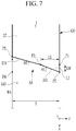
- FIG. 7 shows a top plan view of an end portion on one side of a shim member for setting a width of a slot in a slot die for manufacturing a rechargeable battery electrode according to a fourth exemplary embodiment of the present invention.
- the end portion 37 of the shim member 330 includes a width adjuster A4.
- the width adjuster A4 further includes an additional width increased portion 371 in the width increased portion 341 according to the first exemplary embodiment shim member 30.
- the additional width increased portion 371 is connected to the width increased portion 341 in the discharging direction (y-axis direction), and gradually additionally increases the width W4 of the slot 440 in the discharging direction (y-axis direction).
- the additional width increased portion 371 is formed to have the length (S-Ls) obtained by subtracting the first adjusting length (Ls) from the length (S) in the discharging direction (y-axis direction) in an inclined way with the third angle ⁇ 3 in a direction of the first angle ⁇ 1 with respect to the discharging direction to the fifth reference point P5 from the third reference point P3 that is the end point of the width increased portion 341 of the shim member 430.
- the end portion 37 of the shim member 430 further controls the discharging rate of the active material slurry with the additional width increased portion 371 in addition to the operation of the region L1 of the shim member 30 according to the first exemplary embodiment.
- the third angle ⁇ 3 for the inclined side connecting the third reference point P3 and the fifth reference point P5 to be set with respect to the discharging direction (y-axis direction) may be greater than 0° and equal to or less than 25° (0° ⁇ ⁇ 3 ⁇ 25°).
- the third angle ⁇ 3 is within the range (0° ⁇ ⁇ 3 ⁇ 25°)
- the reduced discharging rate of the active material slurry is additionally appropriately reduced, so the active material slurry may be uniformly coated on the substrate (ES).
- the third angle ⁇ 3 may be equal to or greater than 5° and equal to or less than 20° (5° ⁇ ⁇ 3 ⁇ 20°).
- the third angle ⁇ 3 may additionally appropriately reduce the reduced discharging rate of the active material slurry.
- the additional width increased portion 371 of the end portion 37 may control the discharging rate of the active material slurry throughout the width W4 of the slot 440 to be more uniform.
- FIG. 8 shows a top plan view of an end portion on one side of a shim member for setting a width of a slot in a slot die for manufacturing a rechargeable battery electrode according to a fifth exemplary embodiment of the present invention.
- the end portion 38 of the shim member 530 includes a width adjuster A5.
- the width adjuster A5 further includes a concave round portion 381 at the end of the additional width increased portion of the shim member 430 according to the fourth exemplary embodiment.
- the concave round portion 381 of the end portion 38 is formed to be round at the end of the discharging direction to reduce the width W5 of the slot 540 in the discharging direction.
- the concave round portion 381 of the additional width increased portion may appropriately increase the reduced discharging rate of the active material slurry.
- the concave round portion 381 of the additional width increased portion may control the discharging rate of the active material slurry throughout the width W5 of the slot 540 to be more uniform at the end portion 38.
- FIG. 9 shows a top plan view of an end portion on one side of a shim member for setting a width of a slot in a slot die for manufacturing a rechargeable battery electrode according to a sixth exemplary embodiment of the present invention.
- the width adjuster A6 installed in the end portion 44 of the shim member 630 is formed in a straight line toward the slot 640 in the height direction (z-axis direction) so as to be vertically connected to the first side 13 and the second side 23.
- the width adjuster A6 that forms a straight line controls the rate-controlled active material slurry to be uniform in the height direction of the slot 640.
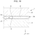
- FIG. 10 shows a top plan view of an end portion on one side of a shim member for setting a width of a slot in a slot die for manufacturing a rechargeable battery electrode according to a seventh exemplary embodiment of the present invention
- FIG. 11 shows a top plan view of an end portion on one side of a shim member for setting a width of a slot in a slot die for manufacturing a rechargeable battery electrode according to an eighth exemplary embodiment of the present invention.
- the width adjusters A7 and A8 installed in the end portions 45 and 46 of the shim members 730 and 830 are respectively formed to be concave round and convex round toward the slots 740 and 840 so as to be connected to the first side 13 and the second side 23 in a round way.
- the concave round width adjuster A7 adjusts the rate-adjusted active material slurry to be a minimum in a center of the slot 740 in the height direction (z-axis direction) and to be a maximum at the respective ends thereof.
- the convex round width adjuster A8 adjusts the rate-adjusted active material slurry to be a maximum in the center of the slot 840 in the height direction (z-axis direction) and to be a minimum at the respective ends thereof.
- the shim members 630, 730, and 830 of the slot dies 6, 7, and 8 according to sixth, seventh, and eighth exemplary embodiments may be selectively applied to the shim members 30, 230, 330, 430, and 530 of the slot dies according to first to fifth exemplary embodiments to more uniformly control the discharging rate of the active material slurry throughout the widths W, W2, W3, W4, and W5 of the slots 40, 240, 340, 440, and 540.
- FIG. 12 shows a graph of a coating thickness relationship of the active material slurry with respect to a width of the slot in the case of using one of slot dies according to exemplary embodiments of the present invention and in the case of using a slot die according to a comparative example.
- the respective ends of the shim member are formed to have a maximum width inside in the discharging direction (y-axis direction) and are formed to become gradually narrower in its width as it approaches an outside, regarding a slot die (not shown) according to a comparative example.
- the slot die according to a comparative example may form a width reduced portion from the first reference point P1 throughout the length (S) of the discharging direction (y-axis direction).
- the width reduced portion maybe formed to be inclined by the size of the first angle ⁇ 1 in the opposite direction to the first angle ⁇ 1.
- FIG. 12 shows a graph for comparing a thickness relationship of the active material slurry with respect to a width W3 of the slot 340, regarding a slot die to which a shim member according to a comparative example is applied and a slot die to which a shim member 330 according to an exemplary embodiment (e.g., a third exemplary embodiment) is applied.
- a relational line L0 according to a comparative example has an edge soaring shape for providing the maximum thickness of the active material slurry at the respective ends of the slot in the width direction.
- the relational line L3 according to an exemplary embodiment provides a generally uniform thickness of the active material slurry of the slot 340 in the width W3 direction.
- FIG. 13 shows a cross-sectional view of an electrode showing a coating thickness of an active material layer with respect to a width of the substrate in a comparative example of an evaluation example
- FIG. 14 shows a cross-sectional view of an electrode showing a coating thickness of an active material layer with respect to a width of the substrate in a comparative example of an evaluation example.
- the electrode Eo according to a comparative example has a big edge soaring shape of the active material layer ALo at the respective ends of the substrate ESo according to the relational line L0.
- the electrode E3 according to an exemplary embodiment may form an active material layer (AL) with a generally uniform thickness in the width direction of the substrate (ES) according to the relational line L3.
Landscapes
- Engineering & Computer Science (AREA)
- Manufacturing & Machinery (AREA)
- Chemical & Material Sciences (AREA)
- Chemical Kinetics & Catalysis (AREA)
- Electrochemistry (AREA)
- General Chemical & Material Sciences (AREA)
- Mechanical Engineering (AREA)
- Battery Electrode And Active Subsutance (AREA)
- Coating Apparatus (AREA)
Abstract
a first block (11) ;
a second block (30) facing the first block (11) ;
and a shim member (33) positioned between the first block (11) and the second block (30) , wherein the first block (11) and the second block (30) are combined to each other to form a slot (131) for discharging an active material slurry, the first block (11) includes a chamber for receiving the active material slurry and forms a first side in a width (01) direction and a discharging direction of the slot (131) , the second block (30) faces the first side to form a second side in the width (01) direction and the discharging direction of the slot (131) , the shim member (33) includes end portions facing each other at respective ends of the first side and the second side and formed in a height direction of the slot (131) , and the end portion (40) includes a width adjuster (A5) protruding to a second reference point (P3) from a first reference point (P2) of the shim member (33) in the width (01) direction by a first adjusting width (Lw), inclined to a third reference point (P4) from the second reference point (P3) with a first angle (81) with respect to the discharging direction, and formed in the discharging direction by a first adjusting length (Ls).
Description
- The present invention relates to a slot die for manufacturing a rechargeable battery electrode. More particularly, the present invention relates to a slot die for manufacturing a rechargeable battery electrode including a shim member for controlling a discharging rate of an active material slurry coated on a substrate.
- A rechargeable battery repeats charging and discharging, differing from a primary cell. A small rechargeable battery is used for portable small electronic devices such as a mobile phone, a laptop computer, or a camcorder. A large capacity and high density rechargeable battery is used to store motor driving power or energy of hybrid vehicles and electric vehicles.
- The rechargeable battery includes an electrode assembly for charging and discharging a current, a case for receiving the electrode assembly and an electrolyte solution, a cap plate combined to an opening of the case, and an electrode end for drawing out the electrode assembly to an outside of the cap plate.
- The electrode assembly may be formed by disposing electrodes on respective sides of a separation film that is an electrical insulator, and spirally winding the separation films and the electrodes, stacking them, or mixing them. The separation film allows charging and discharging of the electrode assembly by separating the electrodes with different polarities and maintaining ion conductivity in the electrode assembly.
- The electrode is formed by coating an active material slurry on the substrate. A slot die is used when the electrode is manufactured by coating the active material slurry on the substrate. The slot die includes a lower block and an upper block for forming a chamber for supplying the active material slurry and setting a height of a slot for discharging the active material slurry, and a shim member installed therebetween and setting a width of a slot.
- In general, regarding the width of the slot set between respective ends of the shim member, when a distribution of discharging rates of the active material slurry becomes non-uniform, a soaring phenomenon of the active material slurry is generated at edges of the respective ends of the substrate in a width direction, and a coating thickness of the active material slurry of the substrate in the width direction becomes non-uniform. In other words, the material slurry becomes higher at the edges relative to the rest of the substrate.
- The above information disclosed in this Background section is only for enhancement of understanding of the background of the invention, and therefore it may contain information that does not form the prior art that is already known to a person of ordinary skill in the art.
- The present invention has been made in an effort to provide a slot die for manufacturing a rechargeable battery electrode for providing a uniform coating thickness of an active material layer in terms of a width of a substrate by providing a uniform discharging rate distribution of an active material slurry in terms of a width of a slot.
- An exemplary embodiment of the present invention provides a slot die for manufacturing a rechargeable battery electrode, including: a first block; a second block facing the first block; and a shim member positioned between the first block and the second block, wherein the first block and the second block are combined to each other to form a slot for discharging an active material slurry, the first block includes a chamber for receiving the active material slurry and forms a first side in a width direction and a discharging direction of the slot, the second block faces the first side to form a second side in the width direction and the discharging direction of the slot, the shim member includes end portions facing each other at respective ends of the first side and the second side and formed in a height direction of the slot, and the end portion includes a width adjuster protruding to a second reference point from a first reference point of the shim member in the width direction by a first adjusting width (Lw), inclined to a third reference point from the second reference point with a first angle (θ1) with respect to the discharging direction, and formed in the discharging direction by a first adjusting length (Ls).
- A width ratio (Lw/W) of the first adjusting width (Lw) vs. a width (W) of the slot may be greater than o and equal to or less than 0.1 (0 < Lw/W ≤ 0.1). The width ratio (Lw/W) of the first adjusting width (Lw) vs. a width (W) of the slot may be equal to or greater than 0.02 and equal to or less than 0.06 (0.02 ≤ Lw/W ≤ 0.06).
- A length ratio (Ls/S) of the first adjusting length (Ls) vs. a length (S) of the slot in a discharging direction may be greater than 0 and equal to or less than 0.5 (0 < Ls/S ≤ 0.5).
- The first angle θ1 may be greater than 0° and equal to or less than 30° (0° < θ1 ≤ 30°).
- The width adjuster may include a width increased portion for gradually increasing a width of the slot from a minimum width of the slot in the discharging direction.
- The width adjuster may further include a width reduced portion connected to the width increased portion in the discharging direction and gradually reducing the width of the slot in the discharging direction.
- The width adjuster may be formed to be inclined with a second angle θ2 in an opposite direction to the first angle with respect to the discharging direction to a fourth reference point from the third reference point of the shim member.
- The second angle θ2 is greater than 0° and equal to or less than 15° (0° < θ2 ≤ 15°).
- The width adjuster may further include a convex round portion further connected to the width reduced portion in the discharging direction, formed to be round at an end of the discharging direction, and increasing a width of the slot in the discharging direction.
- The width adjuster may include an additional width increased portion further connected to the width increased portion in the discharging direction and gradually additionally increasing a width of the slot in the discharging direction.
- The width adjuster may be formed to be inclined with a third angle θ3 in a direction of the first angle with respect to the discharging direction to a fifth reference point from the third reference point of the shim member.
- The third angle θ3 is greater than 0° and equal to or less than 25° (0° < θ3 ≤ 25°).
- The width adjuster may further include a concave round portion further connected to the additional width increased portion in the discharging direction, formed to be round at the end of the discharging direction, and reducing the width of the slot in the discharging direction.
- The width adjuster may be formed in a straight line in the height direction so as to be vertically connected to the first side and the second side.
- The width adjuster may be formed to be concave round or convex round toward the slot so as to be connected to the first side and the second side in a round way.
- The slot die according to the exemplary embodiments of the present invention provides the uniform discharging rate distribution of the active material slurry to prevent the soaring shape of the active material slurry on the edges of the respective ends of the substrate in the width direction, in terms of the width of the slot set between the respective ends of the shim member. Therefore, the uniform coating thickness of the active material layer is obtained in the width direction of the substrate according to the exemplary embodiment.
- According to an aspect of the invention, there is provided a slot die for manufacturing a rechargeable battery electrode, comprising a first block, a second block facing the first block and a shim member positioned between the first block and the second block, the shim member having end portions spaced apart from one another to form a slot for discharging an active material slurry between the end portions and the facing surfaces of the first block and the second block, the first block includes a chamber for receiving the active material slurry, and each of the end portions includes a protrusion that reduces the width of the slot at the end opposite the end at which the active material slurry is discharged, wherein the angle of the protrusion is arranged to provide a substantially uniform discharge rate of the active material slurry across the width of the slot.
-
-
FIG. 1 shows an exploded perspective view of a slot die for manufacturing a rechargeable battery electrode according to a first exemplary embodiment of the present invention. -
FIG. 2 shows a top plan view of a shim member shown inFIG. 1 . -
FIG. 3 shows a cross-sectional view with respect to a line III-III ofFIG. 1 . -
FIG. 4 shows a top plan view of an end portion on one side of a shim member for setting a width of a slot shown inFIG. 2 . -
FIG. 5 shows a top plan view of an end portion on one side of a shim member for setting a width of a slot in a slot die for manufacturing a rechargeable battery electrode according to a second exemplary embodiment of the present invention. -
FIG. 6 shows a top plan view of an end portion on one side of a shim member for setting a width of a slot in a slot die for manufacturing a rechargeable battery electrode according to a third exemplary embodiment of the present invention. -
FIG. 7 shows a top plan view of an end portion on one side of a shim member for setting a width of a slot in a slot die for manufacturing a rechargeable battery electrode according to a fourth exemplary embodiment of the present invention. -
FIG. 8 shows a top plan view of an end portion on one side of a shim member for setting a width of a slot in a slot die for manufacturing a rechargeable battery electrode according to a fifth exemplary embodiment of the present invention. -
FIG. 9 shows a top plan view of an end portion on one side of a shim member for setting a width of a slot in a slot die for manufacturing a rechargeable battery electrode according to a sixth exemplary embodiment of the present invention. -
FIG. 10 shows a top plan view of an end portion on one side of a shim member for setting a width of a slot in a slot die for manufacturing a rechargeable battery electrode according to a seventh exemplary embodiment of the present invention. -
FIG. 11 shows a top plan view of an end portion on one side of a shim member for setting a width of a slot in a slot die for manufacturing a rechargeable battery electrode according to an eighth exemplary embodiment of the present invention. -
FIG. 12 shows a graph of a coating thickness relationship of an active material slurry with respect to a width of a slot in the case of using one of slot dies according to exemplary embodiments of the present invention and in the case of using a slot die according to a comparative example. -
FIG. 13 shows a cross-sectional view of an electrode showing a coating thickness of an active material layer with respect to a width of a substrate in a comparative example of an evaluation example. -
FIG. 14 shows a cross-sectional view of an electrode showing a coating thickness of an active material layer with respect to a width of a substrate in a comparative example of an evaluation example. - The present invention will be described more fully hereinafter with reference to the accompanying drawings, in which exemplary embodiments of the invention are shown. As those skilled in the art would realize, the described embodiments may be modified in various different ways, all without departing from the scope of the present invention. The drawings and description are to be regarded as illustrative in nature and not restrictive. Like reference numerals designate like elements throughout the specification.
-
FIG. 1 shows an exploded perspective view of a slot die for manufacturing a rechargeable battery electrode according to a first exemplary embodiment of the present invention,FIG. 2 shows a top plan view of a shim member shown inFIG. 1 , andFIG. 3 shows a cross-sectional view with respect to a line III-III ofFIG. 1 . - Referring to
FIG. 1 to FIG. 3 , the slot die 1 (a slot die, hereinafter) for manufacturing a rechargeable battery electrode according to a first exemplary embodiment of the present invention includes afirst block 10, asecond block 20, and ashim member 30 installed therebetween. The first andsecond blocks shim member 30 may be fastened by a fasteningmember 131 to form a slot die. - The
first block 10 includes achamber 11 for temporarily storing a supplied active material slurry. Asupply unit 12 is connected to a bottom of thefirst block 10 to supply the active material slurry to thechamber 11. The first andsecond blocks slot 40 for discharging active material slurry. Theslot 40 may be formed to be quadrangular in the x- and z-axis directions (refer toFIG. 9 ), or may be changed to be round in the x-axis direction according to the shape of theshim member 30. - The
first block 10 forms afirst side 13 of theslot 40 in a width direction (x-axis direction) and a discharging direction (y-axis direction), which can also be seen as the bottom surface of theslot 40. Thesecond block 20 forms asecond side 23 of theslot 40 in the width direction (x-axis direction) and the discharging direction (y-axis direction), facing thefirst side 13, and can also be seen as the top surface of the slot. - The
shim member 30 is installed between the first andsecond blocks end portions first side 13 and thesecond side 23 of theslot 40. Theseend portions third side 33 and afourth side 34 of theslot 40 facing each other in the height direction (z-axis direction) and the discharging direction (y-axis direction). - Regarding the
shim member 30, a thickness in the z-axis direction sets a height (H) of theslot 40, a gap (a distance in the x-axis direction) between theend portions slot 40, and the width of the third andfourth sides slot 40. - The slot die 1 temporarily stores the active material slurry supplied by the
supply unit 12 in thechamber 11 and then discharges it through theslot 40, so the active material slurry is applied to the substrate (ES) proceeding to the front of theslot 40 to form an active material layer (AL) (refer toFIG. 12 andFIG. 14 ). -
FIG. 4 shows a top plan view of an end portion on one side of a shim member for setting a width of a slot shown inFIG. 2 . For ease of description,FIG. 4 will exemplify anend portion 32 on one side. Referring toFIG. 2 to FIG. 4 , theend portion 32 includes a width adjuster A1 protruding to a second reference point P2 from a first reference point P1 of theshim member 30 in the width direction (x-axis direction) by a first adjusting width (Lw), inclined to a third reference point P3 from the second reference point P2 with a first angle θ1 with respect to the discharging direction (y-axis direction), and formed in the discharging direction (y-axis direction) by a first adjusting length (Ls). - Substantially, the width adjuster A1 is positioned on the facing third and
fourth sides portion 341 for gradually increasing the width (W) of theslot 40 from a minimum width of theslot 40 with respect to the discharging direction (y-axis direction). - The width increased
portion 341 protrudes to the second reference point P2 from the first reference point P1 of theshim member 30 in the width direction (x-axis direction) by a first adjusting width (Lw), is inclined to the third reference point P3 from the second reference point P2 with the first angle θ1 with respect to the discharging direction (y-axis direction), and is formed in the discharging direction (y-axis direction) by the first adjusting length (Ls). - A region L1 set with the first adjusting width (Lw) and the first adjusting length (Ls) at the
end portion 32 of theshim member 30 increases the discharging rate of the active material slurry in a central portion of theslot 40 in the width direction (x-axis direction), and reduces the discharging rate of the active material slurry on the third andfourth sides slot 40 in the width direction (x-axis direction). That is, the region L1 of theend portion 32 controls the discharging rate of the active material slurry throughout the width (W) of theslot 40 to be more uniform. - The width increased
portion 341 and the region L1 of theend portion 32 will now be described in detail. A width ratio (Lw/W) of the first adjusting width (Lw) vs. width (W) of theslot 40 may be greater than 0 and equal to or less than 0.1 (0 < Lw/W ≤ 0.1). When the width ratio (Lw/W) is within the range (0 < Lw/W ≤ 0.1), the discharging rate of the active material slurry appropriately falls, and the active material slurry may be uniformly coated on the substrate (ES). - Further, the width ratio (Lw/W) of the first adjusting width (Lw) vs. the width (W) of the
slot 40 may be equal to or greater than 0.02 and equal to or less than 0.06 (0.02 ≤ Lw/W ≤ 0.06). In this case, the width ratio (Lw/W) may reduce the discharging rate of the active material slurry. Hence, the width increasedportion 341 and the region L1 of theend portion 32 may control the discharging rate of the active material slurry throughout the width (W) of theslot 40 to be more uniform. - A length ratio (Ls/S) of the first adjusting length (Ls) vs. the length (S) of the
slot 40 in the discharging direction (y-axis direction) may be greater than 0 and equal to or less than 0.5 (0 < Ls/S ≤ 0.5). When the length ratio (Ls/S) is within the range (0 < Ls/S ≤ 0.5), the reduced discharging rate of the active material slurry may be maintained for an appropriate time. - Further, the length ratio (Ls/S) of the first adjusting length (Ls) vs. the length (S) of the
slot 40 in the discharging direction (y-axis direction) may be equal to or greater than 0.05 and equal to or less than 0.2 (0.05 ≤ Ls/S ≤ 0.2). In this case, the length ratio (Ls/S) may maintain the reduced discharging rate of the active material slurry for a predetermined time. Therefore, the width increasedportion 341 and the region L1 of theend portion 32 may control the discharging rate of the active material slurry throughout the width (W) of theslot 40 to be more uniform. - The first angle θ1 given when an inclined side for connecting the second reference point P2 and the third reference point P3 is set for the discharging direction (y-axis direction) may be greater than 0° and equal to or less than 30° (0° < θ1 ≤ 30°). When the first angle θ1 is within the range (0° < θ1 ≤ 30°), the discharging rate of the active material slurry is appropriately reduced, and the active material slurry may be uniformly coated on the substrate (ES).
- Further, the first angle θ1 may be equal to or greater than 5° and equal to or less than 25° (5° ≤ θ1 ≤ 25°). In this case, the first angle θ1 may appropriately reduce the discharging rate of the active material slurry. Therefore, the width increased
portion 341 and the region L1 of theend portion 32 may control the discharging rate of the active material slurry throughout the width (W) of theslot 40 to be more uniform. - In another way, when the active material slurry has lower viscosity than required, an edge spreading phenomenon increases, and an edge sinking phenomenon increases because of an increase of the discharging rate from the respective sides of the
slot 40 in the width direction (x-axis direction). - When the active material slurry has higher viscosity than required, an edge soaring phenomenon is generated, where the material height increases at the edges relative to the height away from the edges. That is, the edge soaring phenomenon may be generated because of reinforcement of surface tension of the active material slurry caused by a reduction of the discharging rate of the active material slurry on the respective sides of the
slot 40 in the width direction (x-axis direction). - Therefore, the active material slurry has viscosity corresponding to a type of the configured material, and the discharging rate on the width direction of the
slot 40 may become uniform within the required viscosity range. - Various exemplary embodiments of the present invention will now be described. The first exemplary embodiment and the above-described exemplary embodiments will be compared, the same configurations will be omitted, and different configurations will be described.
-
FIG. 5 shows a top plan view of an end portion on one side of a shim member for setting a width of a slot in a slot die for manufacturing a rechargeable battery electrode according to a second exemplary embodiment of the present invention. Referring toFIG. 5 , anend portion 35 of theshim member 230 includes a width adjuster A2 on a slot die according to a second exemplary embodiment. The width adjuster A2 further includes a width reducedportion 351 in the width increasedportion 341 of theshim member 30 according to the first exemplary embodiment. The width reducedportion 351 is connected to the width increasedportion 341 in the discharging direction (y-axis direction), and gradually reduces the width W2 of theslot 240 in the discharging direction. - The width reduced
portion 351 is formed to have the length (S-Ls) obtained by subtracting the first adjusting length (Ls) from the length (S) in the discharging direction (y-axis direction) in an inclined way with a second angle θ2 in an opposite direction to the first angle θ1 with respect to the discharging direction (y-axis direction) to the fourth reference point P4 from the third reference point P3 that is an end point of the width increasedportion 341 in theshim member 230. - The
end portion 35 of theshim member 230 further controls the discharging rate of the active material slurry to the width reducedportion 351 in addition to the operation of theshim member 30 and the region L1 according to the first exemplary embodiment. - The second angle θ2 for an inclined side connecting the third reference point P3 and the fourth reference point P4 to be set with respect to the discharging direction (y-axis direction) may be greater than 0° and equal to or less than 15° (0° < θ2 ≤ 15°). When the second angle θ2 is within the range (0° < θ2 ≤ 15°), the reduced discharging rate of the active material slurry appropriately increases, so the active material slurry may be uniformly coated on the substrate (ES).
- Further, the second angle θ2 may be equal to or greater than 5° and equal to or less than 10° (5° ≤ θ2 ≤ 10°). In this case, the second angle θ2 may appropriately increase the reduced discharging rate of the active material slurry. Hence, the width reduced
portion 351 of theend portion 35 may control the discharging rate of the active material slurry throughout the width W2 of theslot 240 to be more uniform. -
FIG. 6 shows a top plan view of an end portion on one side of a shim member for setting a width of a slot in a slot die for manufacturing a rechargeable battery electrode according to a third exemplary embodiment of the present invention. Referring toFIG. 6 , regarding the slot die according to a third exemplary embodiment, theend portion 36 of theshim member 330 includes a width adjuster A3. The width adjuster A3 further includes aconvex round portion 361 at the end of the width reducedportion 351 of theshim member 230 according to the second exemplary embodiment. - The
convex round portion 361 of theend portion 36 is made round at the end of the discharging direction to increase the width W3 of theslot 340 in the discharging direction. In this case, theconvex round portion 361 of the width reducedportion 351 may appropriately reduce the increased discharging rate of the active material slurry. Hence, theconvex round portion 361 of the width reducedportion 351 may control the discharging rate of the active material slurry throughout the width W3 of theslot 340 to be more uniform at theend portion 36. -
FIG. 7 shows a top plan view of an end portion on one side of a shim member for setting a width of a slot in a slot die for manufacturing a rechargeable battery electrode according to a fourth exemplary embodiment of the present invention. Referring toFIG. 7 , regarding the slot die according to the fourth exemplary embodiment, theend portion 37 of theshim member 330 includes a width adjuster A4. The width adjuster A4 further includes an additional width increasedportion 371 in the width increasedportion 341 according to the first exemplaryembodiment shim member 30. The additional width increasedportion 371 is connected to the width increasedportion 341 in the discharging direction (y-axis direction), and gradually additionally increases the width W4 of theslot 440 in the discharging direction (y-axis direction). - The additional width increased
portion 371 is formed to have the length (S-Ls) obtained by subtracting the first adjusting length (Ls) from the length (S) in the discharging direction (y-axis direction) in an inclined way with the third angle θ3 in a direction of the first angle θ1 with respect to the discharging direction to the fifth reference point P5 from the third reference point P3 that is the end point of the width increasedportion 341 of theshim member 430. - The
end portion 37 of theshim member 430 further controls the discharging rate of the active material slurry with the additional width increasedportion 371 in addition to the operation of the region L1 of theshim member 30 according to the first exemplary embodiment. - The third angle θ3 for the inclined side connecting the third reference point P3 and the fifth reference point P5 to be set with respect to the discharging direction (y-axis direction) may be greater than 0° and equal to or less than 25° (0° < θ3 ≤ 25°). When the third angle θ3 is within the range (0° < θ3 ≤ 25°), the reduced discharging rate of the active material slurry is additionally appropriately reduced, so the active material slurry may be uniformly coated on the substrate (ES).
- Further, the third angle θ3 may be equal to or greater than 5° and equal to or less than 20° (5° ≤ θ3 ≤ 20°). In this case, the third angle θ3 may additionally appropriately reduce the reduced discharging rate of the active material slurry. Hence, the additional width increased
portion 371 of theend portion 37 may control the discharging rate of the active material slurry throughout the width W4 of theslot 440 to be more uniform. -
FIG. 8 shows a top plan view of an end portion on one side of a shim member for setting a width of a slot in a slot die for manufacturing a rechargeable battery electrode according to a fifth exemplary embodiment of the present invention. Referring toFIG. 8 , regarding the slot die according to a fifth exemplary embodiment, theend portion 38 of theshim member 530 includes a width adjuster A5. The width adjuster A5 further includes aconcave round portion 381 at the end of the additional width increased portion of theshim member 430 according to the fourth exemplary embodiment. - The
concave round portion 381 of theend portion 38 is formed to be round at the end of the discharging direction to reduce the width W5 of theslot 540 in the discharging direction. In this case, theconcave round portion 381 of the additional width increased portion may appropriately increase the reduced discharging rate of the active material slurry. Hence, theconcave round portion 381 of the additional width increased portion may control the discharging rate of the active material slurry throughout the width W5 of theslot 540 to be more uniform at theend portion 38. -
FIG. 9 shows a top plan view of an end portion on one side of a shim member for setting a width of a slot in a slot die for manufacturing a rechargeable battery electrode according to a sixth exemplary embodiment of the present invention. Referring toFIG. 9 , regarding the slot die 6 according to a sixth exemplary embodiment, the width adjuster A6 installed in theend portion 44 of theshim member 630 is formed in a straight line toward theslot 640 in the height direction (z-axis direction) so as to be vertically connected to thefirst side 13 and thesecond side 23. The width adjuster A6 that forms a straight line controls the rate-controlled active material slurry to be uniform in the height direction of theslot 640. -
FIG. 10 shows a top plan view of an end portion on one side of a shim member for setting a width of a slot in a slot die for manufacturing a rechargeable battery electrode according to a seventh exemplary embodiment of the present invention, andFIG. 11 shows a top plan view of an end portion on one side of a shim member for setting a width of a slot in a slot die for manufacturing a rechargeable battery electrode according to an eighth exemplary embodiment of the present invention. - Referring to
FIG. 10 andFIG. 11 , regarding the slot dies 7 and 8 according to the seventh and eighth exemplary embodiments, the width adjusters A7 and A8 installed in theend portions shim members slots first side 13 and thesecond side 23 in a round way. - The concave round width adjuster A7 adjusts the rate-adjusted active material slurry to be a minimum in a center of the
slot 740 in the height direction (z-axis direction) and to be a maximum at the respective ends thereof. The convex round width adjuster A8 adjusts the rate-adjusted active material slurry to be a maximum in the center of theslot 840 in the height direction (z-axis direction) and to be a minimum at the respective ends thereof. - The
shim members shim members slots - An evaluation example of the coating thicknesses of the active material slurries ALo and AL on the substrates ESo and ES will now be described with reference to
FIG. 12 to FIG. 14 . -
FIG. 12 shows a graph of a coating thickness relationship of the active material slurry with respect to a width of the slot in the case of using one of slot dies according to exemplary embodiments of the present invention and in the case of using a slot die according to a comparative example. The respective ends of the shim member are formed to have a maximum width inside in the discharging direction (y-axis direction) and are formed to become gradually narrower in its width as it approaches an outside, regarding a slot die (not shown) according to a comparative example. - For example, referring to
FIG. 5 , the slot die according to a comparative example may form a width reduced portion from the first reference point P1 throughout the length (S) of the discharging direction (y-axis direction). The width reduced portion maybe formed to be inclined by the size of the first angle θ1 in the opposite direction to the first angle θ1. -
FIG. 12 shows a graph for comparing a thickness relationship of the active material slurry with respect to a width W3 of theslot 340, regarding a slot die to which a shim member according to a comparative example is applied and a slot die to which ashim member 330 according to an exemplary embodiment (e.g., a third exemplary embodiment) is applied. - A relational line L0 according to a comparative example has an edge soaring shape for providing the maximum thickness of the active material slurry at the respective ends of the slot in the width direction. Compared to this, the relational line L3 according to an exemplary embodiment provides a generally uniform thickness of the active material slurry of the
slot 340 in the width W3 direction. -
FIG. 13 shows a cross-sectional view of an electrode showing a coating thickness of an active material layer with respect to a width of the substrate in a comparative example of an evaluation example, andFIG. 14 shows a cross-sectional view of an electrode showing a coating thickness of an active material layer with respect to a width of the substrate in a comparative example of an evaluation example. - Referring to
FIG. 13 andFIG. 14 , the electrode Eo according to a comparative example has a big edge soaring shape of the active material layer ALo at the respective ends of the substrate ESo according to the relational line L0. Compared to this, the electrode E3 according to an exemplary embodiment may form an active material layer (AL) with a generally uniform thickness in the width direction of the substrate (ES) according to the relational line L3. - While this invention has been described in connection with what is presently considered to be practical exemplary embodiments, it is to be understood that the invention is not limited to the disclosed embodiments, but, on the contrary, is intended to cover various modifications and equivalent arrangements included within the scope of the appended claims.
-


Claims (15)
- A slot die for manufacturing a rechargeable battery electrode, comprising:a first block;a second block facing the first block; anda shim member positioned between the first block and the second block, the shim member having end portions spaced apart from one another to form a slot for discharging an active material slurry between the end portions and the facing surfaces of the first block and the second block,the first block includes a chamber for receiving the active material slurry, andeach of the end portions includes a width adjuster protruding to a second reference point from a first reference point of the shim member in the width direction by a first adjusting width (Lw), inclined to a third reference point from the second reference point with a first angle (θ1) with respect to the discharging direction, and formed in the discharging direction by a first adjusting length (Ls).
- The slot die of claim 1, wherein
a width ratio (Lw/W) of the first adjusting width (Lw) vs. a width (W) of the slot is greater than 0 and equal to or less than 0.1 (0 < Lw/W ≤ 0.1), optionally wherein
the width ratio (Lw/W) of the first adjusting width (Lw) vs. a width (W) of the slot is equal to or greater than 0.02 and equal to or less than 0.06 (0.02 ≤ Lw/W ≤ 0.06). - The slot die of claim 1, wherein
a length ratio (Ls/S) of the first adjusting length (Ls) vs. a length (S) of the slot in a discharging direction is greater than 0 and equal to or less than 0.5 (0 < Ls/S ≤ 0.5). - The slot die of claim 1, wherein
the first angle θ1 is greater than 0° and equal to or less than 30° (0° < θ1 ≤ 30°). - The slot die of claim 1, wherein
the width adjuster includes a width increased portion for gradually increasing a width of the slot from a minimum width of the slot in the discharging direction. - The slot die of claim 5, wherein
the width adjuster further includes a width reduced portion connected to the width increased portion in the discharging direction and gradually reducing the width of the slot in the discharging direction. - The slot die of claim 1, wherein
the width adjuster is further formed to be inclined with a second angle θ2 in an opposite direction to the first angle with respect to the discharging direction to a fourth reference point from the third reference point of the shim member. - The slot die of claim 7, wherein
the second angle θ2 is greater than 0° and equal to or less than 15° (0° < θ2 ≤ 15°). - The slot die of claim 6, wherein
the width adjuster further includes a convex round portion further connected to the width reduced portion in the discharging direction, formed to be round at an end of the discharging direction, and increasing a width of the slot in the discharging direction. - The slot die of claim 5, wherein
the width adjuster includes an additional width increased portion further connected to the width increased portion in the discharging direction and gradually additionally increasing a width of the slot in the discharging direction. - The slot die of claim 7, wherein
the width adjuster is formed to be inclined with a third angle θ3 in a direction of the first angle with respect to the discharging direction to a fifth reference point from the third reference point of the shim member. - The slot die of claim 11, wherein
the third angle θ3 is greater than 0° and equal to or less than 25° (0° < θ3 ≤ 25°). - The slot die of claim 10, wherein
the width adjuster further includes a concave round portion further connected to the additional width increased portion in the discharging direction, formed to be round at the end of the discharging direction, and reducing the width of the slot in the discharging direction. - The slot die of claim 1, wherein
the width adjuster is formed in a straight line in the height direction of the slot so as to be vertically connected to the first side and the second side. - The slot die of claim 1, wherein
the width adjuster is formed to be concave round or convex round toward the slot so as to be connected to the first side and the second side in a round way.
Applications Claiming Priority (1)
| Application Number | Priority Date | Filing Date | Title |
|---|---|---|---|
| KR1020190149286A KR102866099B1 (en) | 2019-11-20 | 2019-11-20 | Rechargeable battery electrode manufacturing slot die |
Publications (2)
| Publication Number | Publication Date |
|---|---|
| EP3825094A1 true EP3825094A1 (en) | 2021-05-26 |
| EP3825094B1 EP3825094B1 (en) | 2023-09-06 |
Family
ID=73543192
Family Applications (1)
| Application Number | Title | Priority Date | Filing Date |
|---|---|---|---|
| EP20209037.9A Active EP3825094B1 (en) | 2019-11-20 | 2020-11-20 | Slot die for manufacturing rechargeable battery electrode |
Country Status (6)
| Country | Link |
|---|---|
| US (1) | US11779953B2 (en) |
| EP (1) | EP3825094B1 (en) |
| KR (1) | KR102866099B1 (en) |
| CN (1) | CN112823910B (en) |
| HU (1) | HUE063882T2 (en) |
| PL (1) | PL3825094T3 (en) |
Families Citing this family (9)
| Publication number | Priority date | Publication date | Assignee | Title |
|---|---|---|---|---|
| EP4154994A4 (en) * | 2020-10-28 | 2024-01-31 | LG Energy Solution, Ltd. | Slot die coater |
| KR20220059744A (en) * | 2020-11-03 | 2022-05-10 | 주식회사 엘지에너지솔루션 | Shim for die coater, die coater including the same, and lithium secondary battery including a positive electrode manufactured using the same |
| CN114011645B (en) * | 2021-10-08 | 2024-01-23 | 安徽瑞露科技有限公司 | Battery pole piece coating device |
| KR20230063097A (en) | 2021-11-01 | 2023-05-09 | 주식회사 엘지에너지솔루션 | Apparatus and method for measuring gap of slot die |
| KR102536991B1 (en) | 2021-11-05 | 2023-05-26 | (주)피엔티 | Slot die coater and apparatus for regulating thickness of coated material automatically |
| KR102865379B1 (en) * | 2021-11-12 | 2025-09-25 | 주식회사 엘지에너지솔루션 | Apparatus and method for electrode coating |
| KR102913781B1 (en) * | 2022-01-07 | 2026-01-15 | 주식회사 엘지에너지솔루션 | Electrode for lithium secondary battery and manufacturing method thereof |
| CN114535004B (en) * | 2022-03-23 | 2022-12-27 | 北京大学长三角光电科学研究院 | Coating head and coating machine |
| EP4279184A1 (en) | 2022-05-19 | 2023-11-22 | LG Energy Solution, Ltd. | System for deposition of material |
Citations (6)
| Publication number | Priority date | Publication date | Assignee | Title |
|---|---|---|---|---|
| US20060099289A1 (en) * | 2002-06-17 | 2006-05-11 | Mikio Fukumura | Foam forming die and method of manufacturing foam-formed article using the die |
| CN102527576A (en) * | 2010-12-29 | 2012-07-04 | 三星Sdi株式会社 | Device for applying slurry and producing method thereof |
| US20130236651A1 (en) * | 2012-03-07 | 2013-09-12 | Nitto Denko Corporation | Shim member, die coater, and method for producing coating film |
| KR20160074331A (en) * | 2014-12-18 | 2016-06-28 | 율촌화학 주식회사 | Coating slot die and coating method using the same |
| CN106216179A (en) * | 2016-07-22 | 2016-12-14 | 屠春山 | A kind of convenient adjustment discharging uniform die head pad |
| JP2018089599A (en) * | 2016-12-07 | 2018-06-14 | トヨタ自動車株式会社 | Die |
Family Cites Families (11)
| Publication number | Priority date | Publication date | Assignee | Title |
|---|---|---|---|---|
| JP2004000864A (en) * | 2002-06-03 | 2004-01-08 | Toray Ind Inc | Slit die coater die and color filter manufacturing method using the same |
| JP2006255643A (en) * | 2005-03-18 | 2006-09-28 | Hitachi Chem Co Ltd | Coating machine and coating method using it |
| KR100709228B1 (en) * | 2006-02-21 | 2007-04-18 | 삼성에스디아이 주식회사 | Coater of Slurry Coating Equipment |
| KR101897827B1 (en) | 2012-02-28 | 2018-09-12 | 삼성에스디아이 주식회사 | Slot die for controlling slurry coating width |
| KR101750326B1 (en) | 2012-12-07 | 2017-06-23 | 주식회사 엘지화학 | Improved slot die for chamber structure and coating apparatus having the same |
| KR102106443B1 (en) | 2013-05-24 | 2020-05-04 | 삼성에스디아이 주식회사 | Slit nozzle and slit coating apparatus using thereof |
| KR101643034B1 (en) * | 2013-09-13 | 2016-07-26 | 주식회사 엘지화학 | Slot die coater for production of electrodes |
| KR20170037174A (en) | 2015-09-25 | 2017-04-04 | 코오롱인더스트리 주식회사 | Slot die and method for manufacturing organic solar cell by using the slot die |
| KR101841346B1 (en) | 2016-06-01 | 2018-03-22 | 고려대학교 산학협력단 | Shim for the uniform coating distribution of non-Newtonian coating liquids in side slot die and Slot die coater including the same |
| CN205797680U (en) | 2016-07-01 | 2016-12-14 | 合肥国轩高科动力能源有限公司 | A kind of slit die head for fluid coating of lithium ion battery |
| CN106000796B (en) | 2016-07-01 | 2018-09-18 | 合肥国轩高科动力能源有限公司 | A kind of slit die head for fluid coating of lithium ion battery |
-
2019
- 2019-11-20 KR KR1020190149286A patent/KR102866099B1/en active Active
-
2020
- 2020-11-19 US US16/952,354 patent/US11779953B2/en active Active
- 2020-11-20 HU HUE20209037A patent/HUE063882T2/en unknown
- 2020-11-20 CN CN202011306734.4A patent/CN112823910B/en active Active
- 2020-11-20 EP EP20209037.9A patent/EP3825094B1/en active Active
- 2020-11-20 PL PL20209037.9T patent/PL3825094T3/en unknown
Patent Citations (6)
| Publication number | Priority date | Publication date | Assignee | Title |
|---|---|---|---|---|
| US20060099289A1 (en) * | 2002-06-17 | 2006-05-11 | Mikio Fukumura | Foam forming die and method of manufacturing foam-formed article using the die |
| CN102527576A (en) * | 2010-12-29 | 2012-07-04 | 三星Sdi株式会社 | Device for applying slurry and producing method thereof |
| US20130236651A1 (en) * | 2012-03-07 | 2013-09-12 | Nitto Denko Corporation | Shim member, die coater, and method for producing coating film |
| KR20160074331A (en) * | 2014-12-18 | 2016-06-28 | 율촌화학 주식회사 | Coating slot die and coating method using the same |
| CN106216179A (en) * | 2016-07-22 | 2016-12-14 | 屠春山 | A kind of convenient adjustment discharging uniform die head pad |
| JP2018089599A (en) * | 2016-12-07 | 2018-06-14 | トヨタ自動車株式会社 | Die |
Also Published As
| Publication number | Publication date |
|---|---|
| KR102866099B1 (en) | 2025-09-26 |
| US11779953B2 (en) | 2023-10-10 |
| CN112823910A (en) | 2021-05-21 |
| HUE063882T2 (en) | 2024-02-28 |
| KR20210061578A (en) | 2021-05-28 |
| US20210151732A1 (en) | 2021-05-20 |
| EP3825094B1 (en) | 2023-09-06 |
| PL3825094T3 (en) | 2023-12-18 |
| CN112823910B (en) | 2023-04-11 |
Similar Documents
| Publication | Publication Date | Title |
|---|---|---|
| EP3825094B1 (en) | Slot die for manufacturing rechargeable battery electrode | |
| US7138210B2 (en) | Punched electrode and rechargeable lithium battery using the same | |
| CN108140872B (en) | Electrode assembly including electrode plate having bonded additional tab formed thereon | |
| US20130040191A1 (en) | Rechargeable battery | |
| EP4597738A1 (en) | Battery and electrical apparatus | |
| KR20180032083A (en) | Rechageable battery | |
| KR102734115B1 (en) | A positive electrode and an electrode assembly comprising the positive electrode | |
| KR20210155879A (en) | Slot die comprising protrusions and notches and electrode slurry coating device comprising the same | |
| JP2000082484A (en) | Electrode roll of secondary battery | |
| US20210159497A1 (en) | Electrode assembly | |
| KR102111310B1 (en) | Lithium ion cell for an electrical energy storage, and electrical energy storage | |
| US10910663B2 (en) | Secondary battery | |
| US20240391123A1 (en) | Electrode substrate notching device and gap setting method | |
| EP4485614A1 (en) | Battery pack | |
| EP4494768A1 (en) | Coating device for electrode substrate of rechargeable battery | |
| EP4566724A1 (en) | Slot die for manufacturing rechargeable battery electrode, rechargeable battery electrode, and manufacturing method using the same | |
| US20260077378A1 (en) | Slot die coater | |
| US20250316710A1 (en) | Device for coating electrode tab insulator | |
| EP4741068A1 (en) | Slot die for manufacturing secondary battery electrode | |
| US20260094861A1 (en) | Pouch-Type Battery Cell Pressing Member, Battery Module Including the Same, and Pouch-Type Battery Cell Pressing Method Using the Same | |
| EP4741069A1 (en) | Slot die for manufacturing secondary battery electrode | |
| US20260045618A1 (en) | Ess rack anchoring device and anchoring method | |
| US20250226493A1 (en) | Battery pack | |
| US20260135076A1 (en) | Slot die for manufacturing secondary battery electrode | |
| EP4007051A1 (en) | Battery module cover member having pattern of protrusions protruding in different directions formed thereon, manufacturing method therefor, and battery module including same |
Legal Events
| Date | Code | Title | Description |
|---|---|---|---|
| PUAI | Public reference made under article 153(3) epc to a published international application that has entered the european phase |
Free format text: ORIGINAL CODE: 0009012 |
|
| STAA | Information on the status of an ep patent application or granted ep patent |
Free format text: STATUS: REQUEST FOR EXAMINATION WAS MADE |
|
| 17P | Request for examination filed |
Effective date: 20201120 |
|
| AK | Designated contracting states |
Kind code of ref document: A1 Designated state(s): AL AT BE BG CH CY CZ DE DK EE ES FI FR GB GR HR HU IE IS IT LI LT LU LV MC MK MT NL NO PL PT RO RS SE SI SK SM TR |
|
| RIC1 | Information provided on ipc code assigned before grant |
Ipc: B29C 48/15 20190101ALN20230210BHEP Ipc: B29L 31/34 20060101ALN20230210BHEP Ipc: B05C 5/02 20060101ALI20230210BHEP Ipc: B29C 48/08 20190101ALI20230210BHEP Ipc: B29C 48/30 20190101AFI20230210BHEP |
|
| GRAP | Despatch of communication of intention to grant a patent |
Free format text: ORIGINAL CODE: EPIDOSNIGR1 |
|
| STAA | Information on the status of an ep patent application or granted ep patent |
Free format text: STATUS: GRANT OF PATENT IS INTENDED |
|
| RIC1 | Information provided on ipc code assigned before grant |
Ipc: B29C 48/15 20190101ALN20230309BHEP Ipc: B29L 31/34 20060101ALN20230309BHEP Ipc: B05C 5/02 20060101ALI20230309BHEP Ipc: B29C 48/08 20190101ALI20230309BHEP Ipc: B29C 48/30 20190101AFI20230309BHEP |
|
| INTG | Intention to grant announced |
Effective date: 20230327 |
|
| GRAS | Grant fee paid |
Free format text: ORIGINAL CODE: EPIDOSNIGR3 |
|
| GRAA | (expected) grant |
Free format text: ORIGINAL CODE: 0009210 |
|
| STAA | Information on the status of an ep patent application or granted ep patent |
Free format text: STATUS: THE PATENT HAS BEEN GRANTED |
|
| AK | Designated contracting states |
Kind code of ref document: B1 Designated state(s): AL AT BE BG CH CY CZ DE DK EE ES FI FR GB GR HR HU IE IS IT LI LT LU LV MC MK MT NL NO PL PT RO RS SE SI SK SM TR |
|
| REG | Reference to a national code |
Ref country code: GB Ref legal event code: FG4D |
|
| REG | Reference to a national code |
Ref country code: CH Ref legal event code: EP |
|
| REG | Reference to a national code |
Ref country code: IE Ref legal event code: FG4D |
|
| REG | Reference to a national code |
Ref country code: DE Ref legal event code: R096 Ref document number: 602020017140 Country of ref document: DE |
|
| REG | Reference to a national code |
Ref country code: SE Ref legal event code: TRGR |
|
| REG | Reference to a national code |
Ref country code: LT Ref legal event code: MG9D |
|
| REG | Reference to a national code |
Ref country code: NL Ref legal event code: MP Effective date: 20230906 |
|
| PG25 | Lapsed in a contracting state [announced via postgrant information from national office to epo] |
Ref country code: GR Free format text: LAPSE BECAUSE OF FAILURE TO SUBMIT A TRANSLATION OF THE DESCRIPTION OR TO PAY THE FEE WITHIN THE PRESCRIBED TIME-LIMIT Effective date: 20231207 |
|
| PG25 | Lapsed in a contracting state [announced via postgrant information from national office to epo] |
Ref country code: RS Free format text: LAPSE BECAUSE OF FAILURE TO SUBMIT A TRANSLATION OF THE DESCRIPTION OR TO PAY THE FEE WITHIN THE PRESCRIBED TIME-LIMIT Effective date: 20230906 Ref country code: NO Free format text: LAPSE BECAUSE OF FAILURE TO SUBMIT A TRANSLATION OF THE DESCRIPTION OR TO PAY THE FEE WITHIN THE PRESCRIBED TIME-LIMIT Effective date: 20231206 Ref country code: LV Free format text: LAPSE BECAUSE OF FAILURE TO SUBMIT A TRANSLATION OF THE DESCRIPTION OR TO PAY THE FEE WITHIN THE PRESCRIBED TIME-LIMIT Effective date: 20230906 Ref country code: LT Free format text: LAPSE BECAUSE OF FAILURE TO SUBMIT A TRANSLATION OF THE DESCRIPTION OR TO PAY THE FEE WITHIN THE PRESCRIBED TIME-LIMIT Effective date: 20230906 Ref country code: HR Free format text: LAPSE BECAUSE OF FAILURE TO SUBMIT A TRANSLATION OF THE DESCRIPTION OR TO PAY THE FEE WITHIN THE PRESCRIBED TIME-LIMIT Effective date: 20230906 Ref country code: GR Free format text: LAPSE BECAUSE OF FAILURE TO SUBMIT A TRANSLATION OF THE DESCRIPTION OR TO PAY THE FEE WITHIN THE PRESCRIBED TIME-LIMIT Effective date: 20231207 Ref country code: FI Free format text: LAPSE BECAUSE OF FAILURE TO SUBMIT A TRANSLATION OF THE DESCRIPTION OR TO PAY THE FEE WITHIN THE PRESCRIBED TIME-LIMIT Effective date: 20230906 |
|
| REG | Reference to a national code |
Ref country code: AT Ref legal event code: MK05 Ref document number: 1607939 Country of ref document: AT Kind code of ref document: T Effective date: 20230906 |
|
| REG | Reference to a national code |
Ref country code: HU Ref legal event code: AG4A Ref document number: E063882 Country of ref document: HU |
|
| PG25 | Lapsed in a contracting state [announced via postgrant information from national office to epo] |
Ref country code: NL Free format text: LAPSE BECAUSE OF FAILURE TO SUBMIT A TRANSLATION OF THE DESCRIPTION OR TO PAY THE FEE WITHIN THE PRESCRIBED TIME-LIMIT Effective date: 20230906 |
|
| PG25 | Lapsed in a contracting state [announced via postgrant information from national office to epo] |
Ref country code: IS Free format text: LAPSE BECAUSE OF FAILURE TO SUBMIT A TRANSLATION OF THE DESCRIPTION OR TO PAY THE FEE WITHIN THE PRESCRIBED TIME-LIMIT Effective date: 20240106 |
|
| PG25 | Lapsed in a contracting state [announced via postgrant information from national office to epo] |
Ref country code: AT Free format text: LAPSE BECAUSE OF FAILURE TO SUBMIT A TRANSLATION OF THE DESCRIPTION OR TO PAY THE FEE WITHIN THE PRESCRIBED TIME-LIMIT Effective date: 20230906 |
|
| PG25 | Lapsed in a contracting state [announced via postgrant information from national office to epo] |
Ref country code: ES Free format text: LAPSE BECAUSE OF FAILURE TO SUBMIT A TRANSLATION OF THE DESCRIPTION OR TO PAY THE FEE WITHIN THE PRESCRIBED TIME-LIMIT Effective date: 20230906 |
|
| PG25 | Lapsed in a contracting state [announced via postgrant information from national office to epo] |
Ref country code: SM Free format text: LAPSE BECAUSE OF FAILURE TO SUBMIT A TRANSLATION OF THE DESCRIPTION OR TO PAY THE FEE WITHIN THE PRESCRIBED TIME-LIMIT Effective date: 20230906 Ref country code: RO Free format text: LAPSE BECAUSE OF FAILURE TO SUBMIT A TRANSLATION OF THE DESCRIPTION OR TO PAY THE FEE WITHIN THE PRESCRIBED TIME-LIMIT Effective date: 20230906 Ref country code: IS Free format text: LAPSE BECAUSE OF FAILURE TO SUBMIT A TRANSLATION OF THE DESCRIPTION OR TO PAY THE FEE WITHIN THE PRESCRIBED TIME-LIMIT Effective date: 20240106 Ref country code: ES Free format text: LAPSE BECAUSE OF FAILURE TO SUBMIT A TRANSLATION OF THE DESCRIPTION OR TO PAY THE FEE WITHIN THE PRESCRIBED TIME-LIMIT Effective date: 20230906 Ref country code: EE Free format text: LAPSE BECAUSE OF FAILURE TO SUBMIT A TRANSLATION OF THE DESCRIPTION OR TO PAY THE FEE WITHIN THE PRESCRIBED TIME-LIMIT Effective date: 20230906 Ref country code: CZ Free format text: LAPSE BECAUSE OF FAILURE TO SUBMIT A TRANSLATION OF THE DESCRIPTION OR TO PAY THE FEE WITHIN THE PRESCRIBED TIME-LIMIT Effective date: 20230906 Ref country code: AT Free format text: LAPSE BECAUSE OF FAILURE TO SUBMIT A TRANSLATION OF THE DESCRIPTION OR TO PAY THE FEE WITHIN THE PRESCRIBED TIME-LIMIT Effective date: 20230906 Ref country code: SK Free format text: LAPSE BECAUSE OF FAILURE TO SUBMIT A TRANSLATION OF THE DESCRIPTION OR TO PAY THE FEE WITHIN THE PRESCRIBED TIME-LIMIT Effective date: 20230906 Ref country code: PT Free format text: LAPSE BECAUSE OF FAILURE TO SUBMIT A TRANSLATION OF THE DESCRIPTION OR TO PAY THE FEE WITHIN THE PRESCRIBED TIME-LIMIT Effective date: 20240108 |
|
| PG25 | Lapsed in a contracting state [announced via postgrant information from national office to epo] |
Ref country code: IT Free format text: LAPSE BECAUSE OF FAILURE TO SUBMIT A TRANSLATION OF THE DESCRIPTION OR TO PAY THE FEE WITHIN THE PRESCRIBED TIME-LIMIT Effective date: 20230906 |
|
| REG | Reference to a national code |
Ref country code: DE Ref legal event code: R097 Ref document number: 602020017140 Country of ref document: DE |
|
| REG | Reference to a national code |
Ref country code: CH Ref legal event code: PL |
|
| PG25 | Lapsed in a contracting state [announced via postgrant information from national office to epo] |
Ref country code: MC Free format text: LAPSE BECAUSE OF FAILURE TO SUBMIT A TRANSLATION OF THE DESCRIPTION OR TO PAY THE FEE WITHIN THE PRESCRIBED TIME-LIMIT Effective date: 20230906 |
|
| PG25 | Lapsed in a contracting state [announced via postgrant information from national office to epo] |
Ref country code: DK Free format text: LAPSE BECAUSE OF FAILURE TO SUBMIT A TRANSLATION OF THE DESCRIPTION OR TO PAY THE FEE WITHIN THE PRESCRIBED TIME-LIMIT Effective date: 20230906 |
|
| PLBE | No opposition filed within time limit |
Free format text: ORIGINAL CODE: 0009261 |
|
| STAA | Information on the status of an ep patent application or granted ep patent |
Free format text: STATUS: NO OPPOSITION FILED WITHIN TIME LIMIT |
|
| PG25 | Lapsed in a contracting state [announced via postgrant information from national office to epo] |
Ref country code: LU Free format text: LAPSE BECAUSE OF NON-PAYMENT OF DUE FEES Effective date: 20231120 |
|
| PG25 | Lapsed in a contracting state [announced via postgrant information from national office to epo] |
Ref country code: CH Free format text: LAPSE BECAUSE OF NON-PAYMENT OF DUE FEES Effective date: 20231130 |
|
| PG25 | Lapsed in a contracting state [announced via postgrant information from national office to epo] |
Ref country code: MC Free format text: LAPSE BECAUSE OF FAILURE TO SUBMIT A TRANSLATION OF THE DESCRIPTION OR TO PAY THE FEE WITHIN THE PRESCRIBED TIME-LIMIT Effective date: 20230906 Ref country code: LU Free format text: LAPSE BECAUSE OF NON-PAYMENT OF DUE FEES Effective date: 20231120 Ref country code: DK Free format text: LAPSE BECAUSE OF FAILURE TO SUBMIT A TRANSLATION OF THE DESCRIPTION OR TO PAY THE FEE WITHIN THE PRESCRIBED TIME-LIMIT Effective date: 20230906 Ref country code: CH Free format text: LAPSE BECAUSE OF NON-PAYMENT OF DUE FEES Effective date: 20231130 Ref country code: SI Free format text: LAPSE BECAUSE OF FAILURE TO SUBMIT A TRANSLATION OF THE DESCRIPTION OR TO PAY THE FEE WITHIN THE PRESCRIBED TIME-LIMIT Effective date: 20230906 |
|
| REG | Reference to a national code |
Ref country code: BE Ref legal event code: MM Effective date: 20231130 |
|
| 26N | No opposition filed |
Effective date: 20240607 |
|
| REG | Reference to a national code |
Ref country code: IE Ref legal event code: MM4A |
|
| PG25 | Lapsed in a contracting state [announced via postgrant information from national office to epo] |
Ref country code: IE Free format text: LAPSE BECAUSE OF NON-PAYMENT OF DUE FEES Effective date: 20231120 |
|
| PG25 | Lapsed in a contracting state [announced via postgrant information from national office to epo] |
Ref country code: BE Free format text: LAPSE BECAUSE OF NON-PAYMENT OF DUE FEES Effective date: 20231130 |
|
| PG25 | Lapsed in a contracting state [announced via postgrant information from national office to epo] |
Ref country code: IE Free format text: LAPSE BECAUSE OF NON-PAYMENT OF DUE FEES Effective date: 20231120 Ref country code: BE Free format text: LAPSE BECAUSE OF NON-PAYMENT OF DUE FEES Effective date: 20231130 |
|
| PG25 | Lapsed in a contracting state [announced via postgrant information from national office to epo] |
Ref country code: BG Free format text: LAPSE BECAUSE OF FAILURE TO SUBMIT A TRANSLATION OF THE DESCRIPTION OR TO PAY THE FEE WITHIN THE PRESCRIBED TIME-LIMIT Effective date: 20230906 |
|
| PG25 | Lapsed in a contracting state [announced via postgrant information from national office to epo] |
Ref country code: BG Free format text: LAPSE BECAUSE OF FAILURE TO SUBMIT A TRANSLATION OF THE DESCRIPTION OR TO PAY THE FEE WITHIN THE PRESCRIBED TIME-LIMIT Effective date: 20230906 |
|
| PG25 | Lapsed in a contracting state [announced via postgrant information from national office to epo] |
Ref country code: CY Free format text: LAPSE BECAUSE OF FAILURE TO SUBMIT A TRANSLATION OF THE DESCRIPTION OR TO PAY THE FEE WITHIN THE PRESCRIBED TIME-LIMIT; INVALID AB INITIO Effective date: 20201120 |
|
| PG25 | Lapsed in a contracting state [announced via postgrant information from national office to epo] |
Ref country code: TR Free format text: LAPSE BECAUSE OF FAILURE TO SUBMIT A TRANSLATION OF THE DESCRIPTION OR TO PAY THE FEE WITHIN THE PRESCRIBED TIME-LIMIT Effective date: 20230906 |
|
| PGFP | Annual fee paid to national office [announced via postgrant information from national office to epo] |
Ref country code: HU Payment date: 20251127 Year of fee payment: 6 |
|
| PGFP | Annual fee paid to national office [announced via postgrant information from national office to epo] |
Ref country code: DE Payment date: 20251104 Year of fee payment: 6 |
|
| PGFP | Annual fee paid to national office [announced via postgrant information from national office to epo] |
Ref country code: GB Payment date: 20251030 Year of fee payment: 6 |
|
| PGFP | Annual fee paid to national office [announced via postgrant information from national office to epo] |
Ref country code: FR Payment date: 20251117 Year of fee payment: 6 |
|
| PGFP | Annual fee paid to national office [announced via postgrant information from national office to epo] |
Ref country code: SE Payment date: 20251112 Year of fee payment: 6 |
|
| PGFP | Annual fee paid to national office [announced via postgrant information from national office to epo] |
Ref country code: PL Payment date: 20251031 Year of fee payment: 6 |