EP3824998A1 - Fluidized bed reactor - Google Patents
Fluidized bed reactor Download PDFInfo
- Publication number
- EP3824998A1 EP3824998A1 EP20827956.2A EP20827956A EP3824998A1 EP 3824998 A1 EP3824998 A1 EP 3824998A1 EP 20827956 A EP20827956 A EP 20827956A EP 3824998 A1 EP3824998 A1 EP 3824998A1
- Authority
- EP
- European Patent Office
- Prior art keywords
- fluidized bed
- bed reactor
- catalyst
- dust collector
- catalyst particles
- Prior art date
- Legal status (The legal status is an assumption and is not a legal conclusion. Google has not performed a legal analysis and makes no representation as to the accuracy of the status listed.)
- Granted
Links
Images

Classifications
-
- B—PERFORMING OPERATIONS; TRANSPORTING
- B01—PHYSICAL OR CHEMICAL PROCESSES OR APPARATUS IN GENERAL
- B01J—CHEMICAL OR PHYSICAL PROCESSES, e.g. CATALYSIS OR COLLOID CHEMISTRY; THEIR RELEVANT APPARATUS
- B01J8/00—Chemical or physical processes in general, conducted in the presence of fluids and solid particles; Apparatus for such processes
- B01J8/18—Chemical or physical processes in general, conducted in the presence of fluids and solid particles; Apparatus for such processes with fluidised particles
- B01J8/24—Chemical or physical processes in general, conducted in the presence of fluids and solid particles; Apparatus for such processes with fluidised particles according to "fluidised-bed" technique
- B01J8/38—Chemical or physical processes in general, conducted in the presence of fluids and solid particles; Apparatus for such processes with fluidised particles according to "fluidised-bed" technique with fluidised bed containing a rotatable device or being subject to rotation or to a circulatory movement, i.e. leaving a vessel and subsequently re-entering it
- B01J8/384—Chemical or physical processes in general, conducted in the presence of fluids and solid particles; Apparatus for such processes with fluidised particles according to "fluidised-bed" technique with fluidised bed containing a rotatable device or being subject to rotation or to a circulatory movement, i.e. leaving a vessel and subsequently re-entering it being subject to a circulatory movement only
- B01J8/388—Chemical or physical processes in general, conducted in the presence of fluids and solid particles; Apparatus for such processes with fluidised particles according to "fluidised-bed" technique with fluidised bed containing a rotatable device or being subject to rotation or to a circulatory movement, i.e. leaving a vessel and subsequently re-entering it being subject to a circulatory movement only externally, i.e. the particles leaving the vessel and subsequently re-entering it
-
- B—PERFORMING OPERATIONS; TRANSPORTING
- B01—PHYSICAL OR CHEMICAL PROCESSES OR APPARATUS IN GENERAL
- B01J—CHEMICAL OR PHYSICAL PROCESSES, e.g. CATALYSIS OR COLLOID CHEMISTRY; THEIR RELEVANT APPARATUS
- B01J8/00—Chemical or physical processes in general, conducted in the presence of fluids and solid particles; Apparatus for such processes
- B01J8/0015—Feeding of the particles in the reactor; Evacuation of the particles out of the reactor
- B01J8/004—Feeding of the particles in the reactor; Evacuation of the particles out of the reactor by means of a nozzle
-
- B—PERFORMING OPERATIONS; TRANSPORTING
- B01—PHYSICAL OR CHEMICAL PROCESSES OR APPARATUS IN GENERAL
- B01J—CHEMICAL OR PHYSICAL PROCESSES, e.g. CATALYSIS OR COLLOID CHEMISTRY; THEIR RELEVANT APPARATUS
- B01J8/00—Chemical or physical processes in general, conducted in the presence of fluids and solid particles; Apparatus for such processes
- B01J8/005—Separating solid material from the gas/liquid stream
- B01J8/0055—Separating solid material from the gas/liquid stream using cyclones
-
- B—PERFORMING OPERATIONS; TRANSPORTING
- B01—PHYSICAL OR CHEMICAL PROCESSES OR APPARATUS IN GENERAL
- B01J—CHEMICAL OR PHYSICAL PROCESSES, e.g. CATALYSIS OR COLLOID CHEMISTRY; THEIR RELEVANT APPARATUS
- B01J8/00—Chemical or physical processes in general, conducted in the presence of fluids and solid particles; Apparatus for such processes
- B01J8/005—Separating solid material from the gas/liquid stream
- B01J8/006—Separating solid material from the gas/liquid stream by filtration
-
- B—PERFORMING OPERATIONS; TRANSPORTING
- B01—PHYSICAL OR CHEMICAL PROCESSES OR APPARATUS IN GENERAL
- B01J—CHEMICAL OR PHYSICAL PROCESSES, e.g. CATALYSIS OR COLLOID CHEMISTRY; THEIR RELEVANT APPARATUS
- B01J8/00—Chemical or physical processes in general, conducted in the presence of fluids and solid particles; Apparatus for such processes
- B01J8/18—Chemical or physical processes in general, conducted in the presence of fluids and solid particles; Apparatus for such processes with fluidised particles
- B01J8/1818—Feeding of the fluidising gas
- B01J8/1827—Feeding of the fluidising gas the fluidising gas being a reactant
-
- B—PERFORMING OPERATIONS; TRANSPORTING
- B01—PHYSICAL OR CHEMICAL PROCESSES OR APPARATUS IN GENERAL
- B01J—CHEMICAL OR PHYSICAL PROCESSES, e.g. CATALYSIS OR COLLOID CHEMISTRY; THEIR RELEVANT APPARATUS
- B01J8/00—Chemical or physical processes in general, conducted in the presence of fluids and solid particles; Apparatus for such processes
- B01J8/18—Chemical or physical processes in general, conducted in the presence of fluids and solid particles; Apparatus for such processes with fluidised particles
- B01J8/1836—Heating and cooling the reactor
-
- B—PERFORMING OPERATIONS; TRANSPORTING
- B01—PHYSICAL OR CHEMICAL PROCESSES OR APPARATUS IN GENERAL
- B01J—CHEMICAL OR PHYSICAL PROCESSES, e.g. CATALYSIS OR COLLOID CHEMISTRY; THEIR RELEVANT APPARATUS
- B01J8/00—Chemical or physical processes in general, conducted in the presence of fluids and solid particles; Apparatus for such processes
- B01J8/18—Chemical or physical processes in general, conducted in the presence of fluids and solid particles; Apparatus for such processes with fluidised particles
- B01J8/20—Chemical or physical processes in general, conducted in the presence of fluids and solid particles; Apparatus for such processes with fluidised particles with liquid as a fluidising medium
- B01J8/22—Chemical or physical processes in general, conducted in the presence of fluids and solid particles; Apparatus for such processes with fluidised particles with liquid as a fluidising medium gas being introduced into the liquid
- B01J8/224—Chemical or physical processes in general, conducted in the presence of fluids and solid particles; Apparatus for such processes with fluidised particles with liquid as a fluidising medium gas being introduced into the liquid the particles being subject to a circulatory movement
- B01J8/228—Chemical or physical processes in general, conducted in the presence of fluids and solid particles; Apparatus for such processes with fluidised particles with liquid as a fluidising medium gas being introduced into the liquid the particles being subject to a circulatory movement externally, i.e. the particles leaving the vessel and subsequently re-entering it
-
- B—PERFORMING OPERATIONS; TRANSPORTING
- B01—PHYSICAL OR CHEMICAL PROCESSES OR APPARATUS IN GENERAL
- B01J—CHEMICAL OR PHYSICAL PROCESSES, e.g. CATALYSIS OR COLLOID CHEMISTRY; THEIR RELEVANT APPARATUS
- B01J8/00—Chemical or physical processes in general, conducted in the presence of fluids and solid particles; Apparatus for such processes
- B01J8/18—Chemical or physical processes in general, conducted in the presence of fluids and solid particles; Apparatus for such processes with fluidised particles
- B01J8/24—Chemical or physical processes in general, conducted in the presence of fluids and solid particles; Apparatus for such processes with fluidised particles according to "fluidised-bed" technique
-
- C—CHEMISTRY; METALLURGY
- C07—ORGANIC CHEMISTRY
- C07C—ACYCLIC OR CARBOCYCLIC COMPOUNDS
- C07C253/00—Preparation of carboxylic acid nitriles
- C07C253/24—Preparation of carboxylic acid nitriles by ammoxidation of hydrocarbons or substituted hydrocarbons
- C07C253/26—Preparation of carboxylic acid nitriles by ammoxidation of hydrocarbons or substituted hydrocarbons containing carbon-to-carbon multiple bonds, e.g. unsaturated aldehydes
-
- C—CHEMISTRY; METALLURGY
- C07—ORGANIC CHEMISTRY
- C07C—ACYCLIC OR CARBOCYCLIC COMPOUNDS
- C07C255/00—Carboxylic acid nitriles
- C07C255/01—Carboxylic acid nitriles having cyano groups bound to acyclic carbon atoms
- C07C255/06—Carboxylic acid nitriles having cyano groups bound to acyclic carbon atoms of an acyclic and unsaturated carbon skeleton
- C07C255/07—Mononitriles
- C07C255/08—Acrylonitrile; Methacrylonitrile
-
- B—PERFORMING OPERATIONS; TRANSPORTING
- B01—PHYSICAL OR CHEMICAL PROCESSES OR APPARATUS IN GENERAL
- B01J—CHEMICAL OR PHYSICAL PROCESSES, e.g. CATALYSIS OR COLLOID CHEMISTRY; THEIR RELEVANT APPARATUS
- B01J2208/00—Processes carried out in the presence of solid particles; Reactors therefor
- B01J2208/00008—Controlling the process
- B01J2208/00017—Controlling the temperature
- B01J2208/00106—Controlling the temperature by indirect heat exchange
- B01J2208/00115—Controlling the temperature by indirect heat exchange with heat exchange elements inside the bed of solid particles
- B01J2208/00141—Coils
-
- B—PERFORMING OPERATIONS; TRANSPORTING
- B01—PHYSICAL OR CHEMICAL PROCESSES OR APPARATUS IN GENERAL
- B01J—CHEMICAL OR PHYSICAL PROCESSES, e.g. CATALYSIS OR COLLOID CHEMISTRY; THEIR RELEVANT APPARATUS
- B01J2208/00—Processes carried out in the presence of solid particles; Reactors therefor
- B01J2208/00008—Controlling the process
- B01J2208/00654—Controlling the process by measures relating to the particulate material
-
- B—PERFORMING OPERATIONS; TRANSPORTING
- B01—PHYSICAL OR CHEMICAL PROCESSES OR APPARATUS IN GENERAL
- B01J—CHEMICAL OR PHYSICAL PROCESSES, e.g. CATALYSIS OR COLLOID CHEMISTRY; THEIR RELEVANT APPARATUS
- B01J2208/00—Processes carried out in the presence of solid particles; Reactors therefor
- B01J2208/00796—Details of the reactor or of the particulate material
- B01J2208/00893—Feeding means for the reactants
-
- B—PERFORMING OPERATIONS; TRANSPORTING
- B01—PHYSICAL OR CHEMICAL PROCESSES OR APPARATUS IN GENERAL
- B01J—CHEMICAL OR PHYSICAL PROCESSES, e.g. CATALYSIS OR COLLOID CHEMISTRY; THEIR RELEVANT APPARATUS
- B01J2208/00—Processes carried out in the presence of solid particles; Reactors therefor
- B01J2208/00796—Details of the reactor or of the particulate material
- B01J2208/00893—Feeding means for the reactants
- B01J2208/00902—Nozzle-type feeding elements
-
- B—PERFORMING OPERATIONS; TRANSPORTING
- B01—PHYSICAL OR CHEMICAL PROCESSES OR APPARATUS IN GENERAL
- B01J—CHEMICAL OR PHYSICAL PROCESSES, e.g. CATALYSIS OR COLLOID CHEMISTRY; THEIR RELEVANT APPARATUS
- B01J2208/00—Processes carried out in the presence of solid particles; Reactors therefor
- B01J2208/00796—Details of the reactor or of the particulate material
- B01J2208/00938—Flow distribution elements
-
- B—PERFORMING OPERATIONS; TRANSPORTING
- B01—PHYSICAL OR CHEMICAL PROCESSES OR APPARATUS IN GENERAL
- B01J—CHEMICAL OR PHYSICAL PROCESSES, e.g. CATALYSIS OR COLLOID CHEMISTRY; THEIR RELEVANT APPARATUS
- B01J2208/00—Processes carried out in the presence of solid particles; Reactors therefor
- B01J2208/00796—Details of the reactor or of the particulate material
- B01J2208/00991—Disengagement zone in fluidised-bed reactors
-
- B—PERFORMING OPERATIONS; TRANSPORTING
- B01—PHYSICAL OR CHEMICAL PROCESSES OR APPARATUS IN GENERAL
- B01J—CHEMICAL OR PHYSICAL PROCESSES, e.g. CATALYSIS OR COLLOID CHEMISTRY; THEIR RELEVANT APPARATUS
- B01J8/00—Chemical or physical processes in general, conducted in the presence of fluids and solid particles; Apparatus for such processes
- B01J8/18—Chemical or physical processes in general, conducted in the presence of fluids and solid particles; Apparatus for such processes with fluidised particles
- B01J8/1872—Details of the fluidised bed reactor
Definitions
- the present invention relates to a fluidized bed reactor, and more particularly, to a fluidized bed reactor including a filter portion for collecting a fine catalyst.
- a fluidized bed reactor has been used for various industrial reactions.
- a nitrile compound such as acrylonitrile has been industrially produced by ammoxidation of a hydrocarbon such as propylene.
- a method of producing a nitrile compound a method of carrying out a gas-phase ammoxidation reaction in the presence of a metal oxide catalyst has been generally known.
- a hydrocarbon that is a raw material, ammonia, and oxygen-containing gas such as air may be put into a reactor to carry out an ammoxidation reaction in the presence of the metal oxide catalyst, thereby producing a nitrile compound.
- a catalyst bed is filled with a catalyst, gases such as propylene, ammonia, air, and oxygen are sprayed at a lower portion, the sprayed gaseous components are subjected to an ammoxidation reaction while passing through the catalyst bed, and a stream containing a product obtained by the ammoxidation reaction is discharged as a stream discharged toward an upper portion of the fluidized bed reactor.
- gases such as propylene, ammonia, air, and oxygen
- a dust collector is installed in the fluidized bed reactor to collect the fine catalyst particles, and a stream containing the collected particles is re-supplied to the catalyst bed through a dipleg.
- the stream that is re-supplied to the catalyst bed contains the product in addition to the fine catalyst particles, coke is formed due to the product, which is problematic.
- the collected catalyst is not subjected to the ammoxidation reaction, but is maintained at a reduced state, which causes a reduction in yield of the product.
- the present invention has been made in an effort to solve the problems mentioned in the background art, a fluidized bed reactor for increasing the yield of a product by minimizing a loss of fine catalyst particles and increasing a catalytic activity may be provided.
- an object of the present invention is to reduce fine catalyst particles escaping toward an upper portion of a fluidized bed reactor and prevent coke from being formed due to a product by providing a filter portion below a dust collector provided in the fluidized bed reactor.
- the present invention provides a fluidized bed reactor including: a fluidized bed reactor in which a catalyst bed is provided; a dust collector provided in an upper portion of the fluidized bed reactor and collecting catalyst particles in a gas discharged toward the upper portion of the fluidized bed reactor; and a filter portion provided in a region between the dust collector and the catalyst bed, wherein the filter portion includes a filtering screen and a plurality of conical caps coupled to the filtering screen.
- the fluidized bed reactor according to the present invention may include the filter portion provided below the dust collector to effectively collect fine catalyst particles escaping toward the upper portion of the fluidized bed reactor, and may re-supply the collected fine catalyst particles to the catalyst bed to increase a catalyst activity and the yield of a product.
- the filter portion is installed below the dust collector, such that it is possible to minimize an influence on a behavior of a stream moving from a lower portion of the fluidized bed reactor to the upper portion of the fluidized bed reactor, and minimize the fine catalyst particles discharged toward the upper portion.
- the amount of fine catalyst particles collected by the dust collector and the amount of product are reduced to minimize the amount of stream re-supplied from the dust collector to the catalyst layer, thereby suppressing formation of coke.
- a term "stream” in the present invention may mean a flow of fluid in a process, or may mean a fluid itself flowing in a pipe.
- the "stream” may mean both a fluid itself flowing in a pipe connecting respective devices, and a flow of the fluid.
- the fluid may mean a gas or liquid.
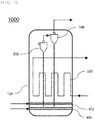
- a fluidized bed reactor 1000 may include: a fluidized bed reactor 1000 in which a catalyst bed 100 is provided; a dust collector 200 provided on an upper portion of the fluidized bed reactor 1000 and collecting catalyst particles in a gas discharged toward the upper portion of the fluidized bed reactor 1000; and a filter portion 300 provided in a region between the dust collector 200 and the catalyst bed 100, in which the filter portion 300 may include a filtering screen 310 and a plurality of conical caps 320 coupled to the filtering screen 310.
- the fluidized bed reactor 1000 may be used in various processes.
- the fluidized bed reactor 1000 may be used in a process of producing acrylonitrile using an ammoxidation reaction of supplied propylene.
- the catalyst bed 100 is provided in the fluidized bed reactor 1000, and gases such as propylene, ammonia, air, and oxygen are sprayed upward from a lower portion of the fluidized bed reactor 1000, and the gas stream is subjected to the ammoxidation reaction while passing through the catalyst bed 100.
- gases such as propylene, ammonia, air, and oxygen
- Acrylonitrile may be produced as a product obtained by the ammoxidation reaction.
- the product obtained by the ammoxidation reaction passes through the catalyst bed 100, moves to the upper portion of the fluidized bed reactor 1000, and is discharged as a stream discharged toward the upper portion of the fluidized bed reactor 1000.
- An operating pressure of the fluidized bed reactor 1000 may be 1 bar to 4 bar.
- the operating pressure of the fluidized bed reactor 1000 may be 1 bar to 3.5 bar, 1 bar to 3 bar, or 1.5 bar to 2.5 bar.
- an operating temperature of the fluidized bed reactor 1000 may be 400°C to 460°C.
- the operating temperature of the fluidized bed reactor 1000 may be 410°C to 450°C, 415°C to 445°C, or 420°C to 440°C.
- the fluidized bed reactor 1000 may be operated under the above-described condition to carry out the ammoxidation reaction of propylene.
- the catalyst bed 100 may be filled with metal oxide catalyst particles.
- the metal oxide catalyst particles may include, for example, one or more metals selected from the group consisting of Mo, Bi, Fe, Co, and K.
- An average size of the catalyst particles may be 150 ⁇ m or less.
- the average size of the catalyst particles may be 50 ⁇ m to 150 ⁇ m, 60 ⁇ m to 130 ⁇ m, or 70 ⁇ m to 110 ⁇ m.
- the catalyst bed 100 may be filled with catalyst particles having an average size within the above range for a large surface area, thereby promoting the ammoxidation reaction of propylene.
- the catalyst particles that fill the catalyst bed 100 may include fine catalyst particles.
- an average size of the fine catalyst particles may be 40 ⁇ m or less.
- the average size of the fine catalyst particles may be 1 ⁇ m to 40 ⁇ m, 1 ⁇ m to 30 ⁇ m, or 10 ⁇ m to 30 ⁇ m.
- the dust collector 200 is installed in the fluidized bed reactor 1000 to collect fine catalyst particles, and a stream containing the collected particles is re-supplied to the catalyst bed 100 through a dipleg.
- the stream that is re-supplied to the catalyst bed 100 contains the product in addition to the fine catalyst particles, coke is formed due to the product, which is problematic.
- the collected catalyst is not subjected to the ammoxidation reaction, but is maintained at a reduced state, which causes a reduction in yield of the product.
- the filter portion 300 to be described later may be provided in a region between the dust collector 200 and the catalyst bed 100 to effectively collect the fine catalyst particles escaping toward the upper portion of the fluidized bed reactor 1000, and the collected fine catalyst particles may be re-supplied to the catalyst bed 100, thereby increasing a catalyst activity and the yield of the product. Further, the amount of the stream re-supplied to the catalyst bed 100 may be minimized to suppress formation of coke.
- the fluidized bed reactor 1000 may include a first spraying portion 400 configured to spray a mixed gas containing propylene and ammonia and provided in the lower portion of the fluidized bed reactor 1000.
- the first spraying portion 400 may include separate pipes for supplying the propylene and the ammonia, respectively.
- the pipe for supplying a propylene stream and the pipe for supplying an ammonia stream may be coupled to each other at an arbitrary region, and the propylene stream and the ammonia stream may be supplied into the fluidized bed reactor 1000 through a main pipe in a next region of the region where the pipes are coupled to each other.
- the main pipe connected to the inside of the fluidized bed reactor 1000 may be freely designed to have a position and shape in accordance with the size and shape of the fluidized bed reactor 1000.
- the first spraying portion 400 may include a spraying nozzle connected to the main pipe.
- the spraying nozzle may spray, toward the upper portion of the fluidized bed reactor 1000, the mixed gas stream containing propylene and ammonia and supplied through the main pipe.
- a plurality of spraying nozzles may be provided on the main pipe while being spaced apart from each other at a predetermined interval.
- a spraying pressure of the spraying nozzle included in the first spraying portion 400 may be 3 bar to 8 bar.
- the spraying pressure of the spraying nozzle may be 4 bar to 7 bar, 4.5 bar to 6.5 bar, or 5 bar to 6 bar.
- the fluidized bed reactor 1000 may include a second spraying portion 410 configured to spray air and provided in a region below the first spraying portion 400.
- the air may mean oxygen (O 2 ).
- the second spraying portion 410 may include a pipe for supplying an air stream. The air stream may be supplied into the fluidized bed reactor 1000 through the pipe.
- the pipe connected to the inside of the fluidized bed reactor 1000 may be freely designed to have a position and shape in accordance with the size and shape of the fluidized bed reactor 1000.
- the second spraying portion 410 may include a spraying nozzle connected to the pipe.
- the spraying nozzle may spray, toward the upper portion of the fluidized bed reactor 1000, the air stream supplied through the main pipe.
- a plurality of spraying nozzles may be provided on the pipe while being spaced apart from each other at a predetermined interval.
- a spraying pressure of the spraying nozzle included in the second spraying portion 410 may be 3 bar to 8 bar.
- the spraying pressure of the spraying nozzle may be 4 bar to 7 bar, 4.5 bar to 6.5 bar, or 5 bar to 6 bar.
- a linear velocity of each of the mixed gas stream containing propylene and ammonia, and the air stream that is discharged toward the upper portion of the fluidized bed reactor 1000 through the first spraying portion 400 and the second spraying portion 410, respectively may be 20 cm/s to 80 cm/s.
- a linear velocity of a stream discharged toward the upper portion of the fluidized bed reactor 1000 through each of the first spraying portion 400 and the second spraying portion 410 may be 30 cm/s to 70 cm/s, 35 cm/s to 65 cm/s, or 40 cm/s to 60 cm/s.
- the mixed gas stream containing propylene and ammonia, and the air stream that are discharged toward the upper portion of the fluidized bed reactor 1000 through the first spraying portion 400 and the second spraying portion 410, respectively, are supplied to the catalyst bed 100 at a linear velocity of 20 cm/s to 80 cm/s, pass the catalyst bed 100, and move to above the catalyst bed 100 together with the fine catalyst particles that fill the catalyst bed 100.
- the fine catalyst particles in the stream may be collected. Fine catalyst particles that are not collected by the filter portion 300 may be separated by the dust collector 200. As a result, it is possible to prevent the fine catalyst particles from being discharged as a stream discharged toward the upper portion of the fluidized bed reactor 1000.
- the filter portion 300 may be provided in the region between the dust collector 200 and the catalyst bed 100, and may collect and separate the fine catalyst particles contained in the stream moving toward the upper portion of the fluidized bed reactor 1000.
- Two or more filter portions 300 may be provided at different heights.
- the filter portion 300 may be installed at a height between a height at which the dust collector 200 of the fluidized bed reactor 1000 is installed and a height at which the uppermost end of the catalyst bed 100 is positioned, and the number of installed filter portions 300 may be freely adjusted depending on the size and shape of the fluidized bed reactor 1000, and the amount of supplied stream.
- two to five filter portions 300 may be provided at different heights in the fluidized bed reactor 1000.
- two or three filter portions 300 may be installed.
- the conical caps 320 installed in each filter portion 300 may be arranged so as not to be positioned on the same vertical line. In this case, it is possible to minimize an influence on a behavior of the stream moving toward the upper portion of the fluidized bed reactor 1000.
- the filter portion 300 may include the filtering screen 310 and the plurality of conical caps 320 coupled to the filtering screen 310.
- the filtering screen 310 may have a mesh form having a size of 5 cm to 20 cm.
- the mesh size of the filtering screen 310 may be 6 cm to 18 cm, 7 cm to 15 cm, or 8 cm to 13 cm.
- the mesh form of the filtering screen 310 is formed using stainless steel wires, and an average diameter of the wires may be 1 mm to 5 mm.
- the average diameter of the wires forming the filtering screen 310 may be 1 mm to 4 mm, 1 mm to 3 mm, or 2 mm to 3 mm.
- the plurality of conical caps 320 may be provided on the filtering screen 310 while being spaced apart from each other at a predetermined interval.
- the number of conical caps 320 may be freely adjusted depending on the size and shape of the fluidized bed reactor 1000.
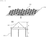
- the conical cap 320 may include a collecting portion 321 in a hollow cone shape collecting the catalyst particles in the gas discharged toward the upper portion of the fluidized bed reactor 1000; and a plurality of connecting portions 322 provided at a predetermined interval along a circumference of the collecting portion 321 and coupled to the filtering screen 310.
- a form in which the filtering screen 310 and the conical cap 320 are coupled to each other is not particularly limited.
- a bottom surface of the cone shape of the conical cap 320 may have an average diameter A of 20 mm to 40 mm, a height B from a vertex of the cone shape in a vertical direction may be 5 mm to 25 mm, and a length C of the connecting portion 322 may be 10 mm to 50 mm.
- the average diameter A of the bottom surface of the cone shape may be 23 mm to 40 mm, 23 mm to 38 mm, or 25 mm to 35 mm.
- the height B from the vertex of the cone shape in the vertical direction may be 5 mm to 20 mm, 5 mm to 20 mm, or 10 mm to 20 mm.
- the length C of the connecting portion 322 may be 10 mm to 45 mm, 13 mm to 45 mm, or 15 mm to 50 mm.
- the average diameter A of the bottom surface of the cone shape, the height B from the vertex of the cone shape in the vertical direction, and the length C of the connecting portion 322 in the conical cap 320 are within the above ranges, respectively, it is possible to minimize an influence on a behavior of the stream moving toward the upper portion of the fluidized bed reactor 1000, and effectively collect the catalyst particles contained in the stream.
- the catalyst particles collected in the collecting portion 321 may be fine catalyst particles having the average size of 40 ⁇ m or less.
- the fine catalyst particles collected in the collecting portion 321 may fall to the catalyst bed 100 again.
- the fine catalyst particles that are not subjected to an ammoxidation reaction of a reactant and are remained at an activated state may be reused, thereby increasing the yield of the product.
- the plurality of conical caps 320 may each have a different height.
- the height of the conical cap 320 may correspond to a sum of the height B from the vertex of the cone shape in the vertical direction and the length C of the connecting portion 322.
- the plurality of conical caps 320 coupled to the filtering screen 310 are designed to each have a different height, it is possible to minimize a change in flow and flow rate of the stream moving upward caused by a reduction in cross-sectional area in the fluidized bed reactor 1000.
- the dust collector 200 may be installed in a region above the filter portion 300 to collect fine catalyst particles that are not collected by the filter portion 300 among fine catalyst particles contained in the stream moving toward the upper portion of the fluidized bed reactor 1000.
- the dust collector 200 may be a cyclone.
- Two or more dust collectors 200 may be installed at different heights in the region above the filter portion 300.
- an exhaust gas may be discharged through an upper portion of the dust collector 200 positioned in the uppermost portion of the fluidized bed reactor 1000.
- the fine catalyst particles collected by the dust collector 200 may be re-supplied to the catalyst bed 100.
- a re-supply line (not illustrated) connected between the dust collector 200 and the catalyst bed 100 may be provided, and the stream containing the fine catalyst particles collected by the dust collector 200 may be re-supplied to the catalyst bed 100 through the re-supply line.
- the fluidized bed reactor 1000 may include a cooling pipe 500 that passes through the catalyst bed 100 in the fluidized bed reactor 1000 and is configured to control a temperature by cooling an ammoxidation reactant in the fluidized bed reactor 1000.
- a cooling water may be supplied to the cooling pipe 500.
- an ammoxidation reaction of a reactant in the fluidized bed reactor 1000 may be carried out at a predetermined temperature.
Landscapes
- Chemical & Material Sciences (AREA)
- Organic Chemistry (AREA)
- Chemical Kinetics & Catalysis (AREA)
- Engineering & Computer Science (AREA)
- Combustion & Propulsion (AREA)
- Devices And Processes Conducted In The Presence Of Fluids And Solid Particles (AREA)
- Low-Molecular Organic Synthesis Reactions Using Catalysts (AREA)
- Catalysts (AREA)
Abstract
Description
- The present application claims the benefit of priority to Korean Patent Application No.
10-2019-0117211, filed on September 24, 2019 - The present invention relates to a fluidized bed reactor, and more particularly, to a fluidized bed reactor including a filter portion for collecting a fine catalyst.
- A fluidized bed reactor has been used for various industrial reactions. For example, a nitrile compound such as acrylonitrile has been industrially produced by ammoxidation of a hydrocarbon such as propylene. As a method of producing a nitrile compound, a method of carrying out a gas-phase ammoxidation reaction in the presence of a metal oxide catalyst has been generally known. As for the gas-phase ammoxidation reaction, a hydrocarbon that is a raw material, ammonia, and oxygen-containing gas such as air may be put into a reactor to carry out an ammoxidation reaction in the presence of the metal oxide catalyst, thereby producing a nitrile compound.
- In the fluidized bed reactor, a catalyst bed is filled with a catalyst, gases such as propylene, ammonia, air, and oxygen are sprayed at a lower portion, the sprayed gaseous components are subjected to an ammoxidation reaction while passing through the catalyst bed, and a stream containing a product obtained by the ammoxidation reaction is discharged as a stream discharged toward an upper portion of the fluidized bed reactor.
- Here, when the stream containing the product is discharged toward the upper portion of the fluidized bed reactor, since a linear velocity of the stream rising to the upper portion of the fluidized bed reactor is high, fine catalyst particles such as a large amount of fine dust are discharged toward the upper portion of the fluidized bed reactor together with the stream rising upward.
- To prevent such a problem, a dust collector is installed in the fluidized bed reactor to collect the fine catalyst particles, and a stream containing the collected particles is re-supplied to the catalyst bed through a dipleg.
- However, since the stream that is re-supplied to the catalyst bed contains the product in addition to the fine catalyst particles, coke is formed due to the product, which is problematic. In addition, the collected catalyst is not subjected to the ammoxidation reaction, but is maintained at a reduced state, which causes a reduction in yield of the product.
- The present invention has been made in an effort to solve the problems mentioned in the background art, a fluidized bed reactor for increasing the yield of a product by minimizing a loss of fine catalyst particles and increasing a catalytic activity may be provided.
- That is, an object of the present invention is to reduce fine catalyst particles escaping toward an upper portion of a fluidized bed reactor and prevent coke from being formed due to a product by providing a filter portion below a dust collector provided in the fluidized bed reactor.
- According to an embodiment of the present invention for solving the above-described problems, the present invention provides a fluidized bed reactor including: a fluidized bed reactor in which a catalyst bed is provided; a dust collector provided in an upper portion of the fluidized bed reactor and collecting catalyst particles in a gas discharged toward the upper portion of the fluidized bed reactor; and a filter portion provided in a region between the dust collector and the catalyst bed, wherein the filter portion includes a filtering screen and a plurality of conical caps coupled to the filtering screen.
- The fluidized bed reactor according to the present invention may include the filter portion provided below the dust collector to effectively collect fine catalyst particles escaping toward the upper portion of the fluidized bed reactor, and may re-supply the collected fine catalyst particles to the catalyst bed to increase a catalyst activity and the yield of a product.
- In addition, according to the present invention, the filter portion is installed below the dust collector, such that it is possible to minimize an influence on a behavior of a stream moving from a lower portion of the fluidized bed reactor to the upper portion of the fluidized bed reactor, and minimize the fine catalyst particles discharged toward the upper portion.
- According to the present invention, the amount of fine catalyst particles collected by the dust collector and the amount of product are reduced to minimize the amount of stream re-supplied from the dust collector to the catalyst layer, thereby suppressing formation of coke.
-
-
FIG. 1 is a schematic diagram illustrating a configuration of a fluidized bed reactor according to an embodiment. -
FIG. 2 is a schematic enlarged diagram illustrating a filter portion included in the fluidized bed reactor according to the embodiment, and a conical cap. -
FIG. 3 is a schematic diagram illustrating a configuration of a fluidized bed reactor according to a comparative example. - Terms and words used in the present invention and claims are not to be construed as a general or dictionary meaning but are to be construed as meanings and concepts meeting the technical ideas of the present invention based on a principle that the inventors can appropriately define the concepts of terms in order to describe their own inventions in the best mode.
- A term "stream" in the present invention may mean a flow of fluid in a process, or may mean a fluid itself flowing in a pipe. Specifically, the "stream" may mean both a fluid itself flowing in a pipe connecting respective devices, and a flow of the fluid. Further, the fluid may mean a gas or liquid.
- Hereinafter, the present invention will be described in more detail with reference to
FIGS. 1 and2 to assist in understanding of the present invention. - According to the present invention, a fluidized
bed reactor 1000 is provided. Thefluidized bed reactor 1000 may include: afluidized bed reactor 1000 in which acatalyst bed 100 is provided; adust collector 200 provided on an upper portion of thefluidized bed reactor 1000 and collecting catalyst particles in a gas discharged toward the upper portion of the fluidizedbed reactor 1000; and afilter portion 300 provided in a region between thedust collector 200 and thecatalyst bed 100, in which thefilter portion 300 may include afiltering screen 310 and a plurality ofconical caps 320 coupled to the filteringscreen 310. - According to an embodiment of the present invention, the fluidized
bed reactor 1000 may be used in various processes. For example, the fluidizedbed reactor 1000 may be used in a process of producing acrylonitrile using an ammoxidation reaction of supplied propylene. - Specifically, the
catalyst bed 100 is provided in the fluidizedbed reactor 1000, and gases such as propylene, ammonia, air, and oxygen are sprayed upward from a lower portion of the fluidizedbed reactor 1000, and the gas stream is subjected to the ammoxidation reaction while passing through thecatalyst bed 100. Acrylonitrile may be produced as a product obtained by the ammoxidation reaction. The product obtained by the ammoxidation reaction passes through thecatalyst bed 100, moves to the upper portion of the fluidizedbed reactor 1000, and is discharged as a stream discharged toward the upper portion of thefluidized bed reactor 1000. - An operating pressure of the fluidized
bed reactor 1000 may be 1 bar to 4 bar. For example, the operating pressure of the fluidizedbed reactor 1000 may be 1 bar to 3.5 bar, 1 bar to 3 bar, or 1.5 bar to 2.5 bar. Further, an operating temperature of the fluidizedbed reactor 1000 may be 400°C to 460°C. For example, the operating temperature of the fluidizedbed reactor 1000 may be 410°C to 450°C, 415°C to 445°C, or 420°C to 440°C. The fluidizedbed reactor 1000 may be operated under the above-described condition to carry out the ammoxidation reaction of propylene. - According to an embodiment of the present invention, the
catalyst bed 100 may be filled with metal oxide catalyst particles. The metal oxide catalyst particles may include, for example, one or more metals selected from the group consisting of Mo, Bi, Fe, Co, and K. - An average size of the catalyst particles may be 150 µm or less. For example, the average size of the catalyst particles may be 50 µm to 150 µm, 60 µm to 130 µm, or 70 µm to 110 µm. The
catalyst bed 100 may be filled with catalyst particles having an average size within the above range for a large surface area, thereby promoting the ammoxidation reaction of propylene. - The catalyst particles that fill the
catalyst bed 100 may include fine catalyst particles. For example, an average size of the fine catalyst particles may be 40 µm or less. For example, the average size of the fine catalyst particles may be 1 µm to 40 µm, 1 µm to 30 µm, or 10 µm to 30 µm. - Since a linear velocity of the stream rising to the upper portion of the fluidized
bed reactor 1000 is high, fine catalyst particles having an average size within the above range are discharged toward the upper portion of the fluidizedbed reactor 1000 together with the stream. To prevent such a problem, according to the related art, thedust collector 200 is installed in the fluidizedbed reactor 1000 to collect fine catalyst particles, and a stream containing the collected particles is re-supplied to thecatalyst bed 100 through a dipleg. - However, since the stream that is re-supplied to the
catalyst bed 100 contains the product in addition to the fine catalyst particles, coke is formed due to the product, which is problematic. In addition, the collected catalyst is not subjected to the ammoxidation reaction, but is maintained at a reduced state, which causes a reduction in yield of the product. - In this regard, according to the present invention, the
filter portion 300 to be described later may be provided in a region between thedust collector 200 and thecatalyst bed 100 to effectively collect the fine catalyst particles escaping toward the upper portion of thefluidized bed reactor 1000, and the collected fine catalyst particles may be re-supplied to thecatalyst bed 100, thereby increasing a catalyst activity and the yield of the product. Further, the amount of the stream re-supplied to thecatalyst bed 100 may be minimized to suppress formation of coke. - According to an embodiment of the present invention, the fluidized
bed reactor 1000 may include afirst spraying portion 400 configured to spray a mixed gas containing propylene and ammonia and provided in the lower portion of the fluidizedbed reactor 1000. Thefirst spraying portion 400 may include separate pipes for supplying the propylene and the ammonia, respectively. The pipe for supplying a propylene stream and the pipe for supplying an ammonia stream may be coupled to each other at an arbitrary region, and the propylene stream and the ammonia stream may be supplied into thefluidized bed reactor 1000 through a main pipe in a next region of the region where the pipes are coupled to each other. - The main pipe connected to the inside of the fluidized
bed reactor 1000 may be freely designed to have a position and shape in accordance with the size and shape of the fluidizedbed reactor 1000. - The
first spraying portion 400 may include a spraying nozzle connected to the main pipe. The spraying nozzle may spray, toward the upper portion of the fluidizedbed reactor 1000, the mixed gas stream containing propylene and ammonia and supplied through the main pipe. - A plurality of spraying nozzles may be provided on the main pipe while being spaced apart from each other at a predetermined interval.
- A spraying pressure of the spraying nozzle included in the first spraying
portion 400 may be 3 bar to 8 bar. For example, the spraying pressure of the spraying nozzle may be 4 bar to 7 bar, 4.5 bar to 6.5 bar, or 5 bar to 6 bar. - According to an embodiment of the present invention, the
fluidized bed reactor 1000 may include asecond spraying portion 410 configured to spray air and provided in a region below thefirst spraying portion 400. For example, the air may mean oxygen (O2). Thesecond spraying portion 410 may include a pipe for supplying an air stream. The air stream may be supplied into thefluidized bed reactor 1000 through the pipe. The pipe connected to the inside of thefluidized bed reactor 1000 may be freely designed to have a position and shape in accordance with the size and shape of thefluidized bed reactor 1000. - The
second spraying portion 410 may include a spraying nozzle connected to the pipe. The spraying nozzle may spray, toward the upper portion of thefluidized bed reactor 1000, the air stream supplied through the main pipe. - A plurality of spraying nozzles may be provided on the pipe while being spaced apart from each other at a predetermined interval.
- A spraying pressure of the spraying nozzle included in the
second spraying portion 410 may be 3 bar to 8 bar. For example, the spraying pressure of the spraying nozzle may be 4 bar to 7 bar, 4.5 bar to 6.5 bar, or 5 bar to 6 bar. - According to an embodiment of the present invention, a linear velocity of each of the mixed gas stream containing propylene and ammonia, and the air stream that is discharged toward the upper portion of the
fluidized bed reactor 1000 through thefirst spraying portion 400 and thesecond spraying portion 410, respectively, may be 20 cm/s to 80 cm/s. For example, a linear velocity of a stream discharged toward the upper portion of thefluidized bed reactor 1000 through each of thefirst spraying portion 400 and thesecond spraying portion 410 may be 30 cm/s to 70 cm/s, 35 cm/s to 65 cm/s, or 40 cm/s to 60 cm/s. - The mixed gas stream containing propylene and ammonia, and the air stream that are discharged toward the upper portion of the
fluidized bed reactor 1000 through thefirst spraying portion 400 and thesecond spraying portion 410, respectively, are supplied to thecatalyst bed 100 at a linear velocity of 20 cm/s to 80 cm/s, pass thecatalyst bed 100, and move to above thecatalyst bed 100 together with the fine catalyst particles that fill thecatalyst bed 100. When the mixed gas stream, the air stream, and a stream containing the fine catalyst particles moved to above thecatalyst bed 100 pass through thefilter portion 300 to be described later, the fine catalyst particles in the stream may be collected. Fine catalyst particles that are not collected by thefilter portion 300 may be separated by thedust collector 200. As a result, it is possible to prevent the fine catalyst particles from being discharged as a stream discharged toward the upper portion of thefluidized bed reactor 1000. - According to an embodiment of the present invention, the
filter portion 300 may be provided in the region between thedust collector 200 and thecatalyst bed 100, and may collect and separate the fine catalyst particles contained in the stream moving toward the upper portion of thefluidized bed reactor 1000. - Two or
more filter portions 300 may be provided at different heights. For example, thefilter portion 300 may be installed at a height between a height at which thedust collector 200 of thefluidized bed reactor 1000 is installed and a height at which the uppermost end of thecatalyst bed 100 is positioned, and the number of installedfilter portions 300 may be freely adjusted depending on the size and shape of thefluidized bed reactor 1000, and the amount of supplied stream. For example, two to fivefilter portions 300 may be provided at different heights in thefluidized bed reactor 1000. For example, two or threefilter portions 300 may be installed. - For example, in a case where two
filter portions 300 are installed at different heights in thefluidized bed reactor 1000, it may be possible to more effectively collect the fine catalyst particles in the stream moving toward the upper portion of thefluidized bed reactor 1000. Further, in a case where twofilter portions 300 are installed at different heights in thefluidized bed reactor 1000, theconical caps 320 installed in eachfilter portion 300 may be arranged so as not to be positioned on the same vertical line. In this case, it is possible to minimize an influence on a behavior of the stream moving toward the upper portion of thefluidized bed reactor 1000. - The
filter portion 300 may include thefiltering screen 310 and the plurality ofconical caps 320 coupled to thefiltering screen 310. - The
filtering screen 310 may have a mesh form having a size of 5 cm to 20 cm. For example, the mesh size of thefiltering screen 310 may be 6 cm to 18 cm, 7 cm to 15 cm, or 8 cm to 13 cm. As thefiltering screen 310 having the mesh size within the above range is installed, it is possible to minimize an influence on a behavior of the stream moving toward the upper portion of thefluidized bed reactor 1000. - The mesh form of the
filtering screen 310 is formed using stainless steel wires, and an average diameter of the wires may be 1 mm to 5 mm. For example, the average diameter of the wires forming thefiltering screen 310 may be 1 mm to 4 mm, 1 mm to 3 mm, or 2 mm to 3 mm. In a case of forming thefiltering screen 310 by using the stainless steel wires having the above average diameter, it is possible to prevent corrosion in thefluidized bed reactor 1000, and minimize an influence on a behavior of the stream moving toward the upper portion of thefluidized bed reactor 1000. - The plurality of
conical caps 320 may be provided on thefiltering screen 310 while being spaced apart from each other at a predetermined interval. For example, the number ofconical caps 320 may be freely adjusted depending on the size and shape of thefluidized bed reactor 1000. - The
conical cap 320 may include a collectingportion 321 in a hollow cone shape collecting the catalyst particles in the gas discharged toward the upper portion of thefluidized bed reactor 1000; and a plurality of connectingportions 322 provided at a predetermined interval along a circumference of the collectingportion 321 and coupled to thefiltering screen 310. A form in which thefiltering screen 310 and theconical cap 320 are coupled to each other is not particularly limited. - A bottom surface of the cone shape of the
conical cap 320 may have an average diameter A of 20 mm to 40 mm, a height B from a vertex of the cone shape in a vertical direction may be 5 mm to 25 mm, and a length C of the connectingportion 322 may be 10 mm to 50 mm. - For example, the average diameter A of the bottom surface of the cone shape may be 23 mm to 40 mm, 23 mm to 38 mm, or 25 mm to 35 mm. Further, the height B from the vertex of the cone shape in the vertical direction may be 5 mm to 20 mm, 5 mm to 20 mm, or 10 mm to 20 mm. Further, the length C of the connecting
portion 322 may be 10 mm to 45 mm, 13 mm to 45 mm, or 15 mm to 50 mm. In a case where the average diameter A of the bottom surface of the cone shape, the height B from the vertex of the cone shape in the vertical direction, and the length C of the connectingportion 322 in theconical cap 320 are within the above ranges, respectively, it is possible to minimize an influence on a behavior of the stream moving toward the upper portion of thefluidized bed reactor 1000, and effectively collect the catalyst particles contained in the stream. - As described above, the catalyst particles collected in the collecting
portion 321 may be fine catalyst particles having the average size of 40 µm or less. The fine catalyst particles collected in the collectingportion 321 may fall to thecatalyst bed 100 again. As a result, the fine catalyst particles that are not subjected to an ammoxidation reaction of a reactant and are remained at an activated state may be reused, thereby increasing the yield of the product. - The plurality of
conical caps 320 may each have a different height. Here, the height of theconical cap 320 may correspond to a sum of the height B from the vertex of the cone shape in the vertical direction and the length C of the connectingportion 322. As such, as the plurality ofconical caps 320 coupled to thefiltering screen 310 are designed to each have a different height, it is possible to minimize a change in flow and flow rate of the stream moving upward caused by a reduction in cross-sectional area in thefluidized bed reactor 1000. - According to an embodiment of the present invention, the
dust collector 200 may be installed in a region above thefilter portion 300 to collect fine catalyst particles that are not collected by thefilter portion 300 among fine catalyst particles contained in the stream moving toward the upper portion of thefluidized bed reactor 1000. For example, thedust collector 200 may be a cyclone. - Two or
more dust collectors 200 may be installed at different heights in the region above thefilter portion 300. Here, an exhaust gas may be discharged through an upper portion of thedust collector 200 positioned in the uppermost portion of thefluidized bed reactor 1000. - According to an embodiment of the present invention, the fine catalyst particles collected by the
dust collector 200 may be re-supplied to thecatalyst bed 100. Specifically, according to the present invention, a re-supply line (not illustrated) connected between thedust collector 200 and thecatalyst bed 100 may be provided, and the stream containing the fine catalyst particles collected by thedust collector 200 may be re-supplied to thecatalyst bed 100 through the re-supply line. As a result, the fine catalyst particles that are not subjected to an ammoxidation reaction of a reactant and are remained at an activated state may be reused, thereby increasing the yield of the product. - According to an embodiment of the present invention, the
fluidized bed reactor 1000 may include acooling pipe 500 that passes through thecatalyst bed 100 in thefluidized bed reactor 1000 and is configured to control a temperature by cooling an ammoxidation reactant in thefluidized bed reactor 1000. A cooling water may be supplied to thecooling pipe 500. As a result, an ammoxidation reaction of a reactant in thefluidized bed reactor 1000 may be carried out at a predetermined temperature. - Although the fluidized bed reactor according to the present invention has been described above and illustrated in the drawings, in the above description and the drawings, only the main configuration for assisting in understanding of the present invention have been described and illustrated. In addition to the processes and devices described above and illustrated in the drawings, processes and devices that are not separately described and illustrated may be appropriately applied and used to implement a particle homogenizing device according to the present invention.
Claims (11)
- A fluidized bed reactor comprising:a fluidized bed reactor in which a catalyst bed is provided;a dust collector provided in an upper portion of the fluidized bed reactor and collecting catalyst particles in a gas discharged toward the upper portion of the fluidized bed reactor; anda filter portion provided in a region between the dust collector and the catalyst bed,wherein the filter portion includes a filtering screen and a plurality of conical caps coupled to the filtering screen.
- The fluidized bed reactor of claim 1, wherein the conical cap includes:a collecting portion in a hollow cone shape collecting the catalyst particles in the gas discharged toward the upper portion of the fluidized bed reactor; anda plurality of connecting portions provided at a predetermined interval along a circumference of the collecting portion and coupled to the filtering screen.
- The fluidized bed reactor of claim 2, wherein an average size of the catalyst particles collected by the collecting portion is 40 µm or less.
- The fluidized bed reactor of claim 2, wherein in the collecting portion, an average diameter of a bottom surface of the cone shape is 20 mm to 40 mm, a height from a vertex of the cone shape in a vertical direction is 5 mm to 25 mm, and a length of the connecting portion is 10 mm to 50 mm.
- The fluidized bed reactor of claim 1, wherein a mesh size of the filtering screen is 5 cm to 20 cm.
- The fluidized bed reactor of claim 1, wherein the plurality of conical caps each have a different height.
- The fluidized bed reactor of claim 1, wherein two or more filter portions are provided at different heights.
- The fluidized bed reactor of claim 1, wherein the fluidized bed reactor is used in a process of producing acrylonitrile using an ammoxidation reaction of supplied propylene.
- The fluidized bed reactor of claim 1, further comprising a first spraying portion configured to spray a mixed gas containing propylene and ammonia and provided in a lower portion of the fluidized bed reactor.
- The fluidized bed reactor of claim 9, further comprising a second spraying portion configured to spray air and provided in a region below the first spraying portion.
- The fluidized bed reactor of claim 1, further comprising a re-supply line connected between the dust collector and the catalyst bed and supplying a stream containing a catalyst collected by the dust collector to the catalyst bed.
Applications Claiming Priority (2)
| Application Number | Priority Date | Filing Date | Title |
|---|---|---|---|
| KR1020190117211A KR102404282B1 (en) | 2019-09-24 | 2019-09-24 | Fluidized bed reactor |
| PCT/KR2020/010585 WO2021060698A1 (en) | 2019-09-24 | 2020-08-11 | Fluidized bed reactor |
Publications (3)
| Publication Number | Publication Date |
|---|---|
| EP3824998A1 true EP3824998A1 (en) | 2021-05-26 |
| EP3824998A4 EP3824998A4 (en) | 2021-11-24 |
| EP3824998B1 EP3824998B1 (en) | 2024-04-10 |
Family
ID=75165094
Family Applications (1)
| Application Number | Title | Priority Date | Filing Date |
|---|---|---|---|
| EP20827956.2A Active EP3824998B1 (en) | 2019-09-24 | 2020-08-11 | Fluidized bed reactor |
Country Status (5)
| Country | Link |
|---|---|
| US (1) | US11369934B2 (en) |
| EP (1) | EP3824998B1 (en) |
| KR (1) | KR102404282B1 (en) |
| CN (1) | CN114828995B (en) |
| WO (1) | WO2021060698A1 (en) |
Family Cites Families (24)
| Publication number | Priority date | Publication date | Assignee | Title |
|---|---|---|---|---|
| US4933149A (en) * | 1984-08-24 | 1990-06-12 | Union Carbide Chemicals And Plastics Company Inc. | Fluidized bed polymerization reactors |
| US6143915A (en) * | 1998-11-23 | 2000-11-07 | Uop Llc | Reaction process in hybrid reactor for propylene ammoxidation |
| CN2484324Y (en) * | 2001-06-21 | 2002-04-03 | 浙江江山化工股份有限公司 | Novel aminomethane synthesizing reactor |
| KR20030089016A (en) * | 2002-05-15 | 2003-11-21 | 송승구 | filtering method for fluidized equipment |
| JP2004290760A (en) * | 2003-03-26 | 2004-10-21 | Hitachi Plant Eng & Constr Co Ltd | Fluidized bed activated carbon water treatment equipment strainer |
| CN1784264A (en) * | 2003-05-09 | 2006-06-07 | 标准石油公司 | Fluidized bed reactor with gas cooler |
| CA2558955A1 (en) * | 2004-03-08 | 2005-09-15 | Shell Internationale Research Maatschappij B.V. | Filter system with filter means retractable into a housing |
| CN101094905B (en) * | 2004-12-30 | 2012-07-25 | 埃克森美孚化学专利公司 | Fluidizing a population of catalyst particles having a low catalyst fines content |
| CN101293637B (en) * | 2008-06-27 | 2010-06-02 | 清华大学 | A device and method for producing chlorine by catalytic oxidation of hydrogen chloride |
| CN201454508U (en) * | 2009-01-19 | 2010-05-12 | 中国石油化工股份有限公司 | Fluidized bed reactor with dust fall ware |
| CN101780389B (en) * | 2009-01-19 | 2012-08-29 | 中国石油化工股份有限公司 | Fluid bed reactor used for gasoline desulfuration |
| KR101586879B1 (en) * | 2013-04-30 | 2016-01-19 | 주식회사 엘지화학 | Fluidized bed reactor and process for manufacturing carbon nanostructures using same |
| CN104587911B (en) | 2013-10-31 | 2017-02-08 | 中国石油化工股份有限公司 | Fluidized bed reactor and application thereof |
| JP6486015B2 (en) * | 2014-04-25 | 2019-03-20 | 三菱ケミカル株式会社 | Fluidized bed reactor |
| CN107252663A (en) * | 2014-06-27 | 2017-10-17 | 英尼奥斯欧洲股份公司 | The control that ammonia for ammonia oxidation reactor is fed |
| JP2016010783A (en) * | 2014-06-30 | 2016-01-21 | フロイント産業株式会社 | Fluidized bed equipment |
| KR20160036305A (en) * | 2014-09-25 | 2016-04-04 | 주식회사 엘지화학 | Distribution Plate Device For Fluidizing Bed Reactor And Fluidizing Bed Reactor With The Same |
| JP6488869B2 (en) * | 2015-05-11 | 2019-03-27 | 三菱ケミカル株式会社 | Fluidized bed reactor and method for producing nitrile compound using the same |
| WO2017069722A1 (en) * | 2015-10-20 | 2017-04-27 | Chidubem Raphael Koroma | Unique exhaust tail pipe/emissions filter |
| CN206715576U (en) * | 2017-01-24 | 2017-12-08 | 李莉 | A kind of filtrating equipment of flue gas of smelting furnace |
| RU2738110C1 (en) | 2017-07-03 | 2020-12-08 | Асахи Касеи Кабусики Кайся | Method of producing unsaturated nitrile |
| JP7105052B2 (en) * | 2017-10-30 | 2022-07-22 | 旭化成株式会社 | Method for producing (meth)acrylonitrile |
| JP2019156737A (en) * | 2018-03-09 | 2019-09-19 | 旭化成株式会社 | Fluid bed reactor and acrylic nitrile production method |
| CN109046186B (en) * | 2018-08-03 | 2020-11-10 | 新奥科技发展有限公司 | Catalyst fluidization unit and fluidized bed catalytic reactor |
-
2019
- 2019-09-24 KR KR1020190117211A patent/KR102404282B1/en active Active
-
2020
- 2020-08-11 WO PCT/KR2020/010585 patent/WO2021060698A1/en not_active Ceased
- 2020-08-11 CN CN202080003912.8A patent/CN114828995B/en active Active
- 2020-08-11 EP EP20827956.2A patent/EP3824998B1/en active Active
- 2020-08-11 US US17/256,573 patent/US11369934B2/en active Active
Also Published As
| Publication number | Publication date |
|---|---|
| KR20210035435A (en) | 2021-04-01 |
| EP3824998B1 (en) | 2024-04-10 |
| CN114828995B (en) | 2024-04-12 |
| KR102404282B1 (en) | 2022-05-30 |
| US11369934B2 (en) | 2022-06-28 |
| US20210370256A1 (en) | 2021-12-02 |
| WO2021060698A1 (en) | 2021-04-01 |
| CN114828995A (en) | 2022-07-29 |
| EP3824998A4 (en) | 2021-11-24 |
Similar Documents
| Publication | Publication Date | Title |
|---|---|---|
| US12485397B2 (en) | Fluidized bed reactor, heat removal water pipe and application thereof in acrylonitrile production | |
| US10363535B1 (en) | Gas-liquid-solid three-phase slurry bed industrial reactor capable of achieving continuous operation | |
| JP2010517763A (en) | Fluidized bed sparger | |
| CN107107013B (en) | Particle Separation Catalytic Chemical Reactors and Particle Separators | |
| US12116331B2 (en) | Gas replacement process, gas replacement apparatus, and nitro compound hydrogenation reaction process | |
| JPH0339807A (en) | Method and device for adjusting temperature level of pulverized solid, provided with heat exchanger with fluidized bed or moving bed section | |
| US11161806B2 (en) | Process for producing compound | |
| US11369934B2 (en) | Fluidized bed reactor | |
| CN106732208B (en) | A kind of injection circulation reactor and application method | |
| EP0878464A1 (en) | PROCESS FOR PRODUCING $g(a).$g(b)-UNSATURATED NITRILE | |
| EP3471873B1 (en) | System components of fluid catalytic reactor systems | |
| CN118718899B (en) | Liquid phase entrainment coupling gas phase feeding device, slurry bed reactor and application thereof | |
| US8968693B2 (en) | Internal cyclone for fluidized bed reactor | |
| CN110099741B (en) | Fluidized catalytic reactor comprising flow directors | |
| KR20260030173A (en) | Swirl nozzle, tubular distributor, fluidized bed reactor, and hydrocarbon ammoxidation method | |
| JP7712217B2 (en) | Catalytic reactor with floating particle trap | |
| CN202909706U (en) | Efficient gas-liquid reactor | |
| CN219051260U (en) | Carbon tube reactor | |
| JPH04202171A (en) | Apparatus for producing alpha,beta-unsaturated nitrile | |
| CA3027702C (en) | System components of fluid catalytic reactor systems | |
| JP2020083832A (en) | Method for producing unsaturated nitrile | |
| US20150202583A1 (en) | Apparatus to reduce catalyst fluidization in regeneration units |
Legal Events
| Date | Code | Title | Description |
|---|---|---|---|
| STAA | Information on the status of an ep patent application or granted ep patent |
Free format text: STATUS: UNKNOWN |
|
| STAA | Information on the status of an ep patent application or granted ep patent |
Free format text: STATUS: THE INTERNATIONAL PUBLICATION HAS BEEN MADE |
|
| PUAI | Public reference made under article 153(3) epc to a published international application that has entered the european phase |
Free format text: ORIGINAL CODE: 0009012 |
|
| STAA | Information on the status of an ep patent application or granted ep patent |
Free format text: STATUS: REQUEST FOR EXAMINATION WAS MADE |
|
| 17P | Request for examination filed |
Effective date: 20201228 |
|
| AK | Designated contracting states |
Kind code of ref document: A1 Designated state(s): AL AT BE BG CH CY CZ DE DK EE ES FI FR GB GR HR HU IE IS IT LI LT LU LV MC MK MT NL NO PL PT RO RS SE SI SK SM TR |
|
| A4 | Supplementary search report drawn up and despatched |
Effective date: 20211022 |
|
| RIC1 | Information provided on ipc code assigned before grant |
Ipc: B01J 8/18 20060101AFI20211018BHEP |
|
| DAV | Request for validation of the european patent (deleted) | ||
| DAX | Request for extension of the european patent (deleted) | ||
| GRAP | Despatch of communication of intention to grant a patent |
Free format text: ORIGINAL CODE: EPIDOSNIGR1 |
|
| STAA | Information on the status of an ep patent application or granted ep patent |
Free format text: STATUS: GRANT OF PATENT IS INTENDED |
|
| INTG | Intention to grant announced |
Effective date: 20240124 |
|
| GRAS | Grant fee paid |
Free format text: ORIGINAL CODE: EPIDOSNIGR3 |
|
| GRAA | (expected) grant |
Free format text: ORIGINAL CODE: 0009210 |
|
| STAA | Information on the status of an ep patent application or granted ep patent |
Free format text: STATUS: THE PATENT HAS BEEN GRANTED |
|
| AK | Designated contracting states |
Kind code of ref document: B1 Designated state(s): AL AT BE BG CH CY CZ DE DK EE ES FI FR GB GR HR HU IE IS IT LI LT LU LV MC MK MT NL NO PL PT RO RS SE SI SK SM TR |
|
| REG | Reference to a national code |
Ref country code: GB Ref legal event code: FG4D |
|
| REG | Reference to a national code |
Ref country code: CH Ref legal event code: EP |
|
| REG | Reference to a national code |
Ref country code: DE Ref legal event code: R096 Ref document number: 602020028893 Country of ref document: DE |
|
| REG | Reference to a national code |
Ref country code: IE Ref legal event code: FG4D |
|
| REG | Reference to a national code |
Ref country code: LT Ref legal event code: MG9D |
|
| REG | Reference to a national code |
Ref country code: NL Ref legal event code: MP Effective date: 20240410 |
|
| REG | Reference to a national code |
Ref country code: AT Ref legal event code: MK05 Ref document number: 1674365 Country of ref document: AT Kind code of ref document: T Effective date: 20240410 |
|
| PG25 | Lapsed in a contracting state [announced via postgrant information from national office to epo] |
Ref country code: NL Free format text: LAPSE BECAUSE OF FAILURE TO SUBMIT A TRANSLATION OF THE DESCRIPTION OR TO PAY THE FEE WITHIN THE PRESCRIBED TIME-LIMIT Effective date: 20240410 |
|
| PG25 | Lapsed in a contracting state [announced via postgrant information from national office to epo] |
Ref country code: NL Free format text: LAPSE BECAUSE OF FAILURE TO SUBMIT A TRANSLATION OF THE DESCRIPTION OR TO PAY THE FEE WITHIN THE PRESCRIBED TIME-LIMIT Effective date: 20240410 |
|
| PG25 | Lapsed in a contracting state [announced via postgrant information from national office to epo] |
Ref country code: IS Free format text: LAPSE BECAUSE OF FAILURE TO SUBMIT A TRANSLATION OF THE DESCRIPTION OR TO PAY THE FEE WITHIN THE PRESCRIBED TIME-LIMIT Effective date: 20240810 |
|
| PG25 | Lapsed in a contracting state [announced via postgrant information from national office to epo] |
Ref country code: BG Free format text: LAPSE BECAUSE OF FAILURE TO SUBMIT A TRANSLATION OF THE DESCRIPTION OR TO PAY THE FEE WITHIN THE PRESCRIBED TIME-LIMIT Effective date: 20240410 |
|
| PG25 | Lapsed in a contracting state [announced via postgrant information from national office to epo] |
Ref country code: HR Free format text: LAPSE BECAUSE OF FAILURE TO SUBMIT A TRANSLATION OF THE DESCRIPTION OR TO PAY THE FEE WITHIN THE PRESCRIBED TIME-LIMIT Effective date: 20240410 Ref country code: FI Free format text: LAPSE BECAUSE OF FAILURE TO SUBMIT A TRANSLATION OF THE DESCRIPTION OR TO PAY THE FEE WITHIN THE PRESCRIBED TIME-LIMIT Effective date: 20240410 |
|
| PG25 | Lapsed in a contracting state [announced via postgrant information from national office to epo] |
Ref country code: GR Free format text: LAPSE BECAUSE OF FAILURE TO SUBMIT A TRANSLATION OF THE DESCRIPTION OR TO PAY THE FEE WITHIN THE PRESCRIBED TIME-LIMIT Effective date: 20240711 |
|
| PG25 | Lapsed in a contracting state [announced via postgrant information from national office to epo] |
Ref country code: PT Free format text: LAPSE BECAUSE OF FAILURE TO SUBMIT A TRANSLATION OF THE DESCRIPTION OR TO PAY THE FEE WITHIN THE PRESCRIBED TIME-LIMIT Effective date: 20240812 |
|
| PG25 | Lapsed in a contracting state [announced via postgrant information from national office to epo] |
Ref country code: ES Free format text: LAPSE BECAUSE OF FAILURE TO SUBMIT A TRANSLATION OF THE DESCRIPTION OR TO PAY THE FEE WITHIN THE PRESCRIBED TIME-LIMIT Effective date: 20240410 |
|
| PG25 | Lapsed in a contracting state [announced via postgrant information from national office to epo] |
Ref country code: AT Free format text: LAPSE BECAUSE OF FAILURE TO SUBMIT A TRANSLATION OF THE DESCRIPTION OR TO PAY THE FEE WITHIN THE PRESCRIBED TIME-LIMIT Effective date: 20240410 |
|
| PG25 | Lapsed in a contracting state [announced via postgrant information from national office to epo] |
Ref country code: PL Free format text: LAPSE BECAUSE OF FAILURE TO SUBMIT A TRANSLATION OF THE DESCRIPTION OR TO PAY THE FEE WITHIN THE PRESCRIBED TIME-LIMIT Effective date: 20240410 |
|
| PG25 | Lapsed in a contracting state [announced via postgrant information from national office to epo] |
Ref country code: LV Free format text: LAPSE BECAUSE OF FAILURE TO SUBMIT A TRANSLATION OF THE DESCRIPTION OR TO PAY THE FEE WITHIN THE PRESCRIBED TIME-LIMIT Effective date: 20240410 |
|
| PG25 | Lapsed in a contracting state [announced via postgrant information from national office to epo] |
Ref country code: PT Free format text: LAPSE BECAUSE OF FAILURE TO SUBMIT A TRANSLATION OF THE DESCRIPTION OR TO PAY THE FEE WITHIN THE PRESCRIBED TIME-LIMIT Effective date: 20240812 Ref country code: PL Free format text: LAPSE BECAUSE OF FAILURE TO SUBMIT A TRANSLATION OF THE DESCRIPTION OR TO PAY THE FEE WITHIN THE PRESCRIBED TIME-LIMIT Effective date: 20240410 Ref country code: NO Free format text: LAPSE BECAUSE OF FAILURE TO SUBMIT A TRANSLATION OF THE DESCRIPTION OR TO PAY THE FEE WITHIN THE PRESCRIBED TIME-LIMIT Effective date: 20240710 Ref country code: LV Free format text: LAPSE BECAUSE OF FAILURE TO SUBMIT A TRANSLATION OF THE DESCRIPTION OR TO PAY THE FEE WITHIN THE PRESCRIBED TIME-LIMIT Effective date: 20240410 Ref country code: IS Free format text: LAPSE BECAUSE OF FAILURE TO SUBMIT A TRANSLATION OF THE DESCRIPTION OR TO PAY THE FEE WITHIN THE PRESCRIBED TIME-LIMIT Effective date: 20240810 Ref country code: HR Free format text: LAPSE BECAUSE OF FAILURE TO SUBMIT A TRANSLATION OF THE DESCRIPTION OR TO PAY THE FEE WITHIN THE PRESCRIBED TIME-LIMIT Effective date: 20240410 Ref country code: GR Free format text: LAPSE BECAUSE OF FAILURE TO SUBMIT A TRANSLATION OF THE DESCRIPTION OR TO PAY THE FEE WITHIN THE PRESCRIBED TIME-LIMIT Effective date: 20240711 Ref country code: FI Free format text: LAPSE BECAUSE OF FAILURE TO SUBMIT A TRANSLATION OF THE DESCRIPTION OR TO PAY THE FEE WITHIN THE PRESCRIBED TIME-LIMIT Effective date: 20240410 Ref country code: ES Free format text: LAPSE BECAUSE OF FAILURE TO SUBMIT A TRANSLATION OF THE DESCRIPTION OR TO PAY THE FEE WITHIN THE PRESCRIBED TIME-LIMIT Effective date: 20240410 Ref country code: BG Free format text: LAPSE BECAUSE OF FAILURE TO SUBMIT A TRANSLATION OF THE DESCRIPTION OR TO PAY THE FEE WITHIN THE PRESCRIBED TIME-LIMIT Effective date: 20240410 Ref country code: AT Free format text: LAPSE BECAUSE OF FAILURE TO SUBMIT A TRANSLATION OF THE DESCRIPTION OR TO PAY THE FEE WITHIN THE PRESCRIBED TIME-LIMIT Effective date: 20240410 Ref country code: RS Free format text: LAPSE BECAUSE OF FAILURE TO SUBMIT A TRANSLATION OF THE DESCRIPTION OR TO PAY THE FEE WITHIN THE PRESCRIBED TIME-LIMIT Effective date: 20240710 |
|
| REG | Reference to a national code |
Ref country code: DE Ref legal event code: R097 Ref document number: 602020028893 Country of ref document: DE |
|
| PG25 | Lapsed in a contracting state [announced via postgrant information from national office to epo] |
Ref country code: DK Free format text: LAPSE BECAUSE OF FAILURE TO SUBMIT A TRANSLATION OF THE DESCRIPTION OR TO PAY THE FEE WITHIN THE PRESCRIBED TIME-LIMIT Effective date: 20240410 |
|
| PG25 | Lapsed in a contracting state [announced via postgrant information from national office to epo] |
Ref country code: EE Free format text: LAPSE BECAUSE OF FAILURE TO SUBMIT A TRANSLATION OF THE DESCRIPTION OR TO PAY THE FEE WITHIN THE PRESCRIBED TIME-LIMIT Effective date: 20240410 |
|
| PG25 | Lapsed in a contracting state [announced via postgrant information from national office to epo] |
Ref country code: CZ Free format text: LAPSE BECAUSE OF FAILURE TO SUBMIT A TRANSLATION OF THE DESCRIPTION OR TO PAY THE FEE WITHIN THE PRESCRIBED TIME-LIMIT Effective date: 20240410 |
|
| PG25 | Lapsed in a contracting state [announced via postgrant information from national office to epo] |
Ref country code: SK Free format text: LAPSE BECAUSE OF FAILURE TO SUBMIT A TRANSLATION OF THE DESCRIPTION OR TO PAY THE FEE WITHIN THE PRESCRIBED TIME-LIMIT Effective date: 20240410 Ref country code: RO Free format text: LAPSE BECAUSE OF FAILURE TO SUBMIT A TRANSLATION OF THE DESCRIPTION OR TO PAY THE FEE WITHIN THE PRESCRIBED TIME-LIMIT Effective date: 20240410 |
|
| PG25 | Lapsed in a contracting state [announced via postgrant information from national office to epo] |
Ref country code: SM Free format text: LAPSE BECAUSE OF FAILURE TO SUBMIT A TRANSLATION OF THE DESCRIPTION OR TO PAY THE FEE WITHIN THE PRESCRIBED TIME-LIMIT Effective date: 20240410 |
|
| PG25 | Lapsed in a contracting state [announced via postgrant information from national office to epo] |
Ref country code: SM Free format text: LAPSE BECAUSE OF FAILURE TO SUBMIT A TRANSLATION OF THE DESCRIPTION OR TO PAY THE FEE WITHIN THE PRESCRIBED TIME-LIMIT Effective date: 20240410 Ref country code: SK Free format text: LAPSE BECAUSE OF FAILURE TO SUBMIT A TRANSLATION OF THE DESCRIPTION OR TO PAY THE FEE WITHIN THE PRESCRIBED TIME-LIMIT Effective date: 20240410 Ref country code: RO Free format text: LAPSE BECAUSE OF FAILURE TO SUBMIT A TRANSLATION OF THE DESCRIPTION OR TO PAY THE FEE WITHIN THE PRESCRIBED TIME-LIMIT Effective date: 20240410 Ref country code: EE Free format text: LAPSE BECAUSE OF FAILURE TO SUBMIT A TRANSLATION OF THE DESCRIPTION OR TO PAY THE FEE WITHIN THE PRESCRIBED TIME-LIMIT Effective date: 20240410 Ref country code: DK Free format text: LAPSE BECAUSE OF FAILURE TO SUBMIT A TRANSLATION OF THE DESCRIPTION OR TO PAY THE FEE WITHIN THE PRESCRIBED TIME-LIMIT Effective date: 20240410 Ref country code: CZ Free format text: LAPSE BECAUSE OF FAILURE TO SUBMIT A TRANSLATION OF THE DESCRIPTION OR TO PAY THE FEE WITHIN THE PRESCRIBED TIME-LIMIT Effective date: 20240410 |
|
| PG25 | Lapsed in a contracting state [announced via postgrant information from national office to epo] |
Ref country code: IT Free format text: LAPSE BECAUSE OF FAILURE TO SUBMIT A TRANSLATION OF THE DESCRIPTION OR TO PAY THE FEE WITHIN THE PRESCRIBED TIME-LIMIT Effective date: 20240410 |
|
| PLBE | No opposition filed within time limit |
Free format text: ORIGINAL CODE: 0009261 |
|
| STAA | Information on the status of an ep patent application or granted ep patent |
Free format text: STATUS: NO OPPOSITION FILED WITHIN TIME LIMIT |
|
| 26N | No opposition filed |
Effective date: 20250113 |
|
| REG | Reference to a national code |
Ref country code: CH Ref legal event code: PL |
|
| PG25 | Lapsed in a contracting state [announced via postgrant information from national office to epo] |
Ref country code: LU Free format text: LAPSE BECAUSE OF NON-PAYMENT OF DUE FEES Effective date: 20240811 |
|
| PG25 | Lapsed in a contracting state [announced via postgrant information from national office to epo] |
Ref country code: SI Free format text: LAPSE BECAUSE OF FAILURE TO SUBMIT A TRANSLATION OF THE DESCRIPTION OR TO PAY THE FEE WITHIN THE PRESCRIBED TIME-LIMIT Effective date: 20240410 Ref country code: MC Free format text: LAPSE BECAUSE OF FAILURE TO SUBMIT A TRANSLATION OF THE DESCRIPTION OR TO PAY THE FEE WITHIN THE PRESCRIBED TIME-LIMIT Effective date: 20240410 Ref country code: CH Free format text: LAPSE BECAUSE OF NON-PAYMENT OF DUE FEES Effective date: 20240831 |
|
| REG | Reference to a national code |
Ref country code: BE Ref legal event code: MM Effective date: 20240831 |
|
| PG25 | Lapsed in a contracting state [announced via postgrant information from national office to epo] |
Ref country code: BE Free format text: LAPSE BECAUSE OF NON-PAYMENT OF DUE FEES Effective date: 20240831 |
|
| PG25 | Lapsed in a contracting state [announced via postgrant information from national office to epo] |
Ref country code: IE Free format text: LAPSE BECAUSE OF NON-PAYMENT OF DUE FEES Effective date: 20240811 |
|
| PG25 | Lapsed in a contracting state [announced via postgrant information from national office to epo] |
Ref country code: SE Free format text: LAPSE BECAUSE OF FAILURE TO SUBMIT A TRANSLATION OF THE DESCRIPTION OR TO PAY THE FEE WITHIN THE PRESCRIBED TIME-LIMIT Effective date: 20240410 |
|
| PGFP | Annual fee paid to national office [announced via postgrant information from national office to epo] |
Ref country code: DE Payment date: 20250721 Year of fee payment: 6 |
|
| PGFP | Annual fee paid to national office [announced via postgrant information from national office to epo] |
Ref country code: GB Payment date: 20250722 Year of fee payment: 6 |
|
| PGFP | Annual fee paid to national office [announced via postgrant information from national office to epo] |
Ref country code: FR Payment date: 20250725 Year of fee payment: 6 |
|
| PG25 | Lapsed in a contracting state [announced via postgrant information from national office to epo] |
Ref country code: CY Free format text: LAPSE BECAUSE OF FAILURE TO SUBMIT A TRANSLATION OF THE DESCRIPTION OR TO PAY THE FEE WITHIN THE PRESCRIBED TIME-LIMIT; INVALID AB INITIO Effective date: 20200811 |
|
| PG25 | Lapsed in a contracting state [announced via postgrant information from national office to epo] |
Ref country code: HU Free format text: LAPSE BECAUSE OF FAILURE TO SUBMIT A TRANSLATION OF THE DESCRIPTION OR TO PAY THE FEE WITHIN THE PRESCRIBED TIME-LIMIT; INVALID AB INITIO Effective date: 20200811 |