EP3824953B1 - Obtention d'un spectre d'énergie d'un domaine technique à faisceau ionique focalisé - Google Patents
Obtention d'un spectre d'énergie d'un domaine technique à faisceau ionique focalisé Download PDFInfo
- Publication number
- EP3824953B1 EP3824953B1 EP19210528.6A EP19210528A EP3824953B1 EP 3824953 B1 EP3824953 B1 EP 3824953B1 EP 19210528 A EP19210528 A EP 19210528A EP 3824953 B1 EP3824953 B1 EP 3824953B1
- Authority
- EP
- European Patent Office
- Prior art keywords
- energy
- ion beam
- spectrum
- idd
- focused ion
- Prior art date
- Legal status (The legal status is an assumption and is not a legal conclusion. Google has not performed a legal analysis and makes no representation as to the accuracy of the status listed.)
- Active
Links
- 238000010884 ion-beam technique Methods 0.000 title claims description 108
- 238000001228 spectrum Methods 0.000 title claims description 89
- 238000009826 distribution Methods 0.000 claims description 27
- 238000004590 computer program Methods 0.000 claims description 23
- 238000000034 method Methods 0.000 claims description 23
- 238000004422 calculation algorithm Methods 0.000 claims description 11
- 150000002500 ions Chemical class 0.000 description 8
- 238000002560 therapeutic procedure Methods 0.000 description 7
- 238000010586 diagram Methods 0.000 description 6
- 230000005855 radiation Effects 0.000 description 4
- 206010028980 Neoplasm Diseases 0.000 description 3
- 230000006870 function Effects 0.000 description 3
- 238000005259 measurement Methods 0.000 description 3
- 230000003287 optical effect Effects 0.000 description 3
- 201000011510 cancer Diseases 0.000 description 2
- 210000000920 organ at risk Anatomy 0.000 description 2
- 238000001959 radiotherapy Methods 0.000 description 2
- 238000013459 approach Methods 0.000 description 1
- 238000004364 calculation method Methods 0.000 description 1
- 229910052799 carbon Inorganic materials 0.000 description 1
- -1 carbon ions Chemical class 0.000 description 1
- 238000010894 electron beam technology Methods 0.000 description 1
- 238000002665 ion therapy Methods 0.000 description 1
- 239000002245 particle Substances 0.000 description 1
- 230000002093 peripheral effect Effects 0.000 description 1
- 230000002085 persistent effect Effects 0.000 description 1
- 238000003860 storage Methods 0.000 description 1
Images


Classifications
-
- A—HUMAN NECESSITIES
- A61—MEDICAL OR VETERINARY SCIENCE; HYGIENE
- A61N—ELECTROTHERAPY; MAGNETOTHERAPY; RADIATION THERAPY; ULTRASOUND THERAPY
- A61N5/00—Radiation therapy
- A61N5/10—X-ray therapy; Gamma-ray therapy; Particle-irradiation therapy
- A61N5/1048—Monitoring, verifying, controlling systems and methods
- A61N5/1064—Monitoring, verifying, controlling systems and methods for adjusting radiation treatment in response to monitoring
- A61N5/1065—Beam adjustment
-
- A—HUMAN NECESSITIES
- A61—MEDICAL OR VETERINARY SCIENCE; HYGIENE
- A61N—ELECTROTHERAPY; MAGNETOTHERAPY; RADIATION THERAPY; ULTRASOUND THERAPY
- A61N5/00—Radiation therapy
- A61N5/10—X-ray therapy; Gamma-ray therapy; Particle-irradiation therapy
- A61N5/103—Treatment planning systems
-
- H—ELECTRICITY
- H01—ELECTRIC ELEMENTS
- H01J—ELECTRIC DISCHARGE TUBES OR DISCHARGE LAMPS
- H01J37/00—Discharge tubes with provision for introducing objects or material to be exposed to the discharge, e.g. for the purpose of examination or processing thereof
- H01J37/30—Electron-beam or ion-beam tubes for localised treatment of objects
- H01J37/304—Controlling tubes by information coming from the objects or from the beam, e.g. correction signals
-
- A—HUMAN NECESSITIES
- A61—MEDICAL OR VETERINARY SCIENCE; HYGIENE
- A61N—ELECTROTHERAPY; MAGNETOTHERAPY; RADIATION THERAPY; ULTRASOUND THERAPY
- A61N5/00—Radiation therapy
- A61N5/10—X-ray therapy; Gamma-ray therapy; Particle-irradiation therapy
- A61N5/1048—Monitoring, verifying, controlling systems and methods
- A61N5/1071—Monitoring, verifying, controlling systems and methods for verifying the dose delivered by the treatment plan
-
- H—ELECTRICITY
- H01—ELECTRIC ELEMENTS
- H01J—ELECTRIC DISCHARGE TUBES OR DISCHARGE LAMPS
- H01J37/00—Discharge tubes with provision for introducing objects or material to be exposed to the discharge, e.g. for the purpose of examination or processing thereof
- H01J37/02—Details
- H01J37/04—Arrangements of electrodes and associated parts for generating or controlling the discharge, e.g. electron-optical arrangement, ion-optical arrangement
- H01J37/05—Electron or ion-optical arrangements for separating electrons or ions according to their energy or mass
-
- A—HUMAN NECESSITIES
- A61—MEDICAL OR VETERINARY SCIENCE; HYGIENE
- A61N—ELECTROTHERAPY; MAGNETOTHERAPY; RADIATION THERAPY; ULTRASOUND THERAPY
- A61N5/00—Radiation therapy
- A61N5/10—X-ray therapy; Gamma-ray therapy; Particle-irradiation therapy
- A61N2005/1085—X-ray therapy; Gamma-ray therapy; Particle-irradiation therapy characterised by the type of particles applied to the patient
- A61N2005/1087—Ions; Protons
- A61N2005/1088—Ions; Protons generated by laser radiation
Definitions
- the present disclosure relates to the field of radiation therapy and in particular to generating radiation therapy plans while restricting to a subset of fluence elements.
- a beam of ions e.g. protons or heavier ions, such as carbon ions
- the target volume can e.g. represent a cancer tumour.
- the ions penetrate the tissue and deliver a dose of energy to destroy cancer cells.
- An advantage of ion beam therapy is that there is a significant peak in the dose distribution, known as the Bragg peak.
- the Bragg peak is a peak of dose delivery occurring at a certain depth, after which the dose delivery falls of quickly. This can be compared with electron beam therapy or X-ray therapy where the peak occurs very close to entering the tissue and dose fall off cannot be controlled with the same sharp fall off as for ion therapy.
- the depth of the Bragg peak in the patient can be controlled by adjusting an energy amount of the ions. Lateral position can be controlled using electromagnets to deflect the beam.
- a spot in ion beam therapy refers to a collection of ions of a specific energy level at a specific lateral location. The number of particles delivered to a spot is commonly referred to as the spot weight.
- the target volume can be covered with a desired dose distribution. This procedure is called active scanning ion beam therapy, also known as pencil beam scanning.
- the planning of how the spots should be delivered is performed in a treatment planning system.
- the treatment planning system determines a set of spots, typically to fulfil some criteria with respect to target coverage and healthy tissue sparing.
- the spots are then communicated to the ion beam treatment delivery system, which delivers the ion beam.
- the treatment planning system and the ion beam treatment delivery system are connected in a way that is known in the art per se.
- a Bragg peak chamber is often used to measure delivery of a single spot in the form of an integrated depth dose (IDD).
- IDD integrated depth dose
- a fraction of the dose delivered by the single spot may be lost in the measurement, with the result that the measured IDD does not represent the complete IDD. If this discrepancy is not accounted for, the modelled delivery may significantly deviate from the total delivered dose. In the prior art, this discrepancy has been compensated for by adjusting the measured IDDs prior to using them in the beam modelling of the Treatment Planning System (TPS).
- TPS Treatment Planning System
- Prior art document WO 2004/109717 describes a method for calculating and simulating the proton/ion energy spectrum of a radiation treatment.
- One object is to improve modelling of delivery of ion beams.
- the method is performed in a spectrum determiner and comprises the steps of: simulating doses, in at least two dimensions, of a set of nominally mono energetic focused ion beams, wherein the energies of the set cover a range of supported energies of the ion beam treatment delivery system; determining a lateral extension of a Bragg peak chamber to evaluate; calculating a set of theoretic component IDD curves, CIDDs, by laterally integrating the dose of the simulated set of the nominally mono energetic focused ion beams, over the lateral extension of the Bragg peak chamber; storing calculated CIDDs; obtaining a measured IDD of a focused ion beam with a nominal energy using the Bragg peak chamber; and performing a fit of a linear combination of CIDDs, wherein all CIDD weights are equal to, or greater than zero, to the measured IDD, to determine an energy spectrum for the focused ion beam with the nominal beam energy.
- each simulated nominally mono energetic focused ion beam may have an energy distribution with a standard deviation that is smaller than the standard deviation of the energy distribution of the focused ion beam of the treatment delivery system.
- each simulated nominally mono energetic focused ion beam may be strictly mono energetic.
- the steps of obtaining a measured IDD and performing a fit may be repeated for a plurality of nominal beam energies.
- the method further comprises the step of: determining the energy spectrum for an additional nominal beam energy of the ion beam treatment delivery system by interpolation between previously determined energy spectra.
- the method may further comprise the step of: using the energy spectrum as input to Monte Carlo based dose computation algorithms.
- the method may further comprise the step of: generating a complete IDD using the energy spectrum and a second set of CIDDs that are laterally integrated over a larger area than that used to determine the CIDDs used for determining the energy spectra, the complete IDD being usable as input to analytical dose computation algorithms.
- a spectrum determiner for obtaining an energy spectrum of a focused ion beam, generated by an ion beam treatment delivery system, for a specific nominal energy, when a Bragg peak chamber is used to measure an integrated depth dose, IDD.
- the spectrum determiner comprises: a processor; and a memory storing instructions that, when executed by the processor, cause the spectrum determiner to: simulate doses, in at least two dimensions, of a set of nominally mono energetic focused ion beams, wherein the energies of the set cover a range of supported energies of the ion beam treatment delivery system; determine a lateral extension of a Bragg peak chamber to evaluate; calculate a set of theoretic component IDD curves, CIDDs, by laterally integrating the dose of the simulated set of the nominally mono energetic focused ion beams, over the lateral extension of the Bragg peak chamber; store calculated CIDDs; obtain a measured IDD of a focused ion beam with a nominal energy using the Bragg peak chamber; and perform a fit of a linear combination of CIDDs, wherein all CIDD weights are equal to, or greater than zero, to the measured IDD, to determine an energy spectrum for the focused ion beam with the nominal beam energy.
- the energy distribution of each simulated nominally mono energetic focused ion beam may have an energy distribution with a standard deviation that is smaller than the standard deviation of the energy distribution of the focused ion beam of the treatment delivery system
- each simulated nominally mono energetic focused ion beam may be strictly mono energetic.
- the spectrum determiner may further comprise instructions that, when executed by the processor, cause the spectrum determiner to: repeat the instructions to obtain a measured IDD and perform a fit for a plurality of nominal beam energies, and determine the energy spectrum for an additional nominal beam energy of the ion beam treatment delivery system by interpolation between previously determined energy spectra.
- the spectrum determiner may further comprise instructions that, when executed by the processor, cause the spectrum determiner to: use the energy spectrum as input to Monte Carlo based dose computation algorithms.
- the spectrum determiner may further comprise instructions that, when executed by the processor, cause the spectrum determiner to: generate a complete IDD using the energy spectrum and a second set of CIDDs that are laterally integrated over a larger area than that used to determine the CIDDs used for determining the energy spectra, the complete IDD being usable as input to analytical dose computation algorithms.
- a computer program for obtaining an energy spectrum of a focused ion beam, generated by an ion beam treatment delivery system, for a specific nominal energy, when a Bragg peak chamber is used to measure an integrated depth dose, IDD.
- the computer program comprises computer program code which, when run on a spectrum determiner causes the spectrum determiner to: simulate doses, in at least two dimensions, of a set of nominally mono energetic focused ion beams, wherein the energies of the set cover a range of supported energies of the ion beam treatment delivery system; determine a lateral extension of a Bragg peak chamber to evaluate; calculate a set of theoretic component IDD curves, CIDDs, by laterally integrating the dose of the simulated set of the nominally mono energetic focused ion beams, over the lateral extension of the Bragg peak chamber; store calculated CIDDs; obtain a measured IDD of a focused ion beam with a nominal energy using the Bragg peak chamber; and perform a fit of a linear combination of CIDDs, wherein all CIDD weights are equal to, or greater than zero, to the measured IDD, to determine an energy spectrum for the focused ion beam with the nominal beam energy.
- a computer program product comprising a computer program according to the third aspect and a computer readable means on which the computer program is stored.
- FIG 1 is a schematic drawing illustrating an environment in which embodiments presented herein can be applied.
- a treatment planning system 1 determines how radiation doses are to be delivered to a target volume 3 of a patient. More specifically, the treatment planning system 1 supplies a treatment plan 7 to an ion beam treatment delivery system 2.
- the treatment plan 7 specifies weights for a plurality of geometrically defined scanning spots. Each weight defines an amount of radiation provided at the respective scanning spot, to thereby provide radiation dose to the target volume 3.
- the treatment plan is delivered by the ion beam treatment delivery system 2 using a scanned ion beam, delivering dose to the patient in scanning spots.
- the scanning spot is defined by a lateral scan position for the beam and a beam energy.
- the treatment plan 7 is made up of a distribution of scanning spots for ion beam therapy, to thereby define dose delivery in three dimensions to the target volume 3.
- the ion beam treatment delivery system 2 Based on the treatment plan 7, the ion beam treatment delivery system 2 generates an ion beam 12 that is scanned spot by spot over the target volume 3 of a patient. Each scanning spot generates a spot dose distribution in the target volume 3 of the patient.
- depth is represented along a z axis.
- the location of the dose maximum (Bragg peak) of a spot dose distribution depthwise, i.e. along the z axis, is controlled by the kinetic energy of the ions; higher energy results in a deeper location of the dose maximum.
- the lateral position in two dimensions is controlled using electromagnets to deflect the beam 12. In this way, the ion beam treatment delivery system 2 delivers the scanning spots in three dimensions in accordance with the treatment plan 7.
- Fig 2 is a schematic diagram illustrating lateral extension as a function of depth of the dose delivered by a single focused ion beam 11. Depth is indicated by the z axis and the vertical axis indicates a lateral direction. It can there be seen how a core dose delivery 11 (containing most of the dose delivery) of the ion beam 12 extends laterally from the centre of the ion beam 12, especially as it approaches the Bragg peak.
- a Bragg peak chamber is used to measure dose delivery in the form of integrated depth dose (IDD).
- the Bragg peak chamber to be any type of dosimetric device that is used to measure the IDD of a focused ion beam.
- the Bragg peak chamber has a finite lateral extension 14.
- lateral extension 14 of the Bragg peak chamber covers the lateral extension of the core dose delivery 11, there is a small amount of dose that is delivered all the way to a peripheral dose delivery 13. Consequently, there will be some delivery of dose outside the finite lateral extension 14 of the Bragg peak chamber, which will thus not be captured by the Bragg peak chamber.
- Fig 3 is a schematic diagram illustrating the difference between total dose delivery 10 and measured dose delivery 10', measured using a Bragg peak chamber.
- the total dose delivery 10 as well as the measured dose delivery 10' illustrate the presence of the Bragg peak at a specific depth and a sharp drop-off thereafter.
- the finite lateral extension 14 of the Bragg peak chamber due to the finite lateral extension 14 of the Bragg peak chamber, there will be small amounts of dose delivery which is not captured by the Bragg peak chamber. It is for this reason that there is a discrepancy between the measured dose delivery 10' and the total dose delivery 10. In the prior art, this discrepancy has been compensated for numerically.
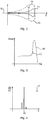
- Fig 4 is a schematic histogram illustrating the energy spectrum of a single ion beam in the ion beam treatment delivery system 2 of Fig 1 .
- the single ion beam has a nominal energy, which is the configured energy in the ion beam treatment delivery system for this particular ion beam.
- Energy E is shown along the x axis and the y axis indicates distribution of energies in the ion beam, dN/dE.
- the energy intervals, i.e. the size of each bin for the energies, along the x axis can e.g. be 0.2 MeV.
- the ion beam has a certain nominal energy 18. However, as seen in the histogram, there is some variation in dose delivery for different energies around the nominal energy 18. In other words, in a real ion beam treatment delivery system, there is some variation in the energy level in ions of the ion beam, reflected by the energy spectrum 17 illustrated in Fig 4 .
- Figs 5A-C are flow charts illustrating methods for obtaining an energy spectrum of a focused ion beam.
- the focused ion beam is generated by the ion beam treatment delivery system, for a specific nominal energy.
- a Bragg peak chamber is used to measure an integrated depth dose, IDD. The methods are performed in a spectrum determiner. First, embodiments illustrated by Fig 5A will be described.
- the spectrum determiner simulates doses, in at least two dimensions (i.e. in two or three dimensions), of a set of nominally mono energetic focused ion beams.
- the energies of the set cover a range of supported energies of the ion beam treatment delivery system. As an example, the energies of the set cover between 5 MeV to 250 MeV. In one embodiment, the spacing between the simulated nominally mono energetic ion beams in the set is 0.2 MeV.
- each simulated nominally mono energetic focused ion beam does not need to be strictly mono energetic, as long as the energy distribution of the simulated ion beam is narrow compared to that of the ion beam treatment delivery system.
- the energy distribution of the mono energetic focused ion beams can have a standard deviation that is smaller than the standard deviation of the energy distribution of the focused ion beam of the treatment delivery system.
- the energy distribution of each simulated nominally mono energetic focused ion beam is strictly mono energetic.
- the spectrum determiner determines a lateral extension of a Bragg peak chamber to evaluate.
- the lateral extension can be a diameter of a circular Bragg peak chamber or the area of the Bragg peak chamber.
- the spectrum determiner calculates a set of theoretic component IDD curves, here denoted CIDDs. This calculation is performed by laterally integrating the dose of the simulated set of the nominally mono energetic focused ion beams, over the lateral extension of the Bragg peak chamber.
- the CIDDs are simulated measurements corresponding to in lateral extension to the size of the Bragg peak chamber.
- the spectrum determiner stores the calculated CIDDs.
- the CIDDs can be precalculated and stored in advance, long before the measurement with the Bragg peak chamber occurs. Furthermore, CIDDs can be precalculated for several sizes of Bragg peak chambers, and only the CIDDs of the Bragg peak chamber used is later employed.
- the spectrum determiner obtains a measured IDD of a focused ion beam with a nominal energy using the Bragg peak chamber.
- the spectrum determiner performs a fit of a linear combination of CIDDs to the measured IDD (with the CIDDs corresponding in lateral extension to the Bragg peak chamber used in step 48). All CIDD weights are equal to, or greater than zero in this linear combination. In this way, an energy spectrum for the focused ion beam with the nominal beam energy is determined.
- the fit can e.g. be performed using a least squares method.
- steps 48 and 50 are repeated for a plurality of nominal beam energies.
- the method can further comprise an optional determine additional energy spectrum step 52.
- the spectrum determiner determines the energy spectrum for an additional nominal beam energy of the ion beam treatment delivery system by interpolation between previously determined energy spectra.
- step 52 can optionally be performed in this embodiment also.
- the spectrum determiner uses the energy spectrum as input to Monte Carlo based dose computation algorithms.
- step 52 can optionally be performed in this embodiment also.
- the spectrum determiner In a generate IDD step 56, the spectrum determiner generates a complete IDD (corresponding to the example shown in Fig 3 ) using the energy spectrum and a second set of CIDDs that are laterally integrated over a larger area than that used to determine the CIDDs used for determining the energy spectra.
- the complete IDD is then usable as input to analytical dose computation algorithms.
- Fig 6 is a schematic diagram illustrating components of the spectrum determiner 5 of Fig 1 according to one embodiment.
- the spectrum determiner 1 forms part of a host device, such as the treatment planning system 1 of Fig 1
- one or more of the mentioned components can be shared with the host device.
- a processor 60 is provided using any combination of one or more of a suitable central processing unit (CPU), multiprocessor, microcontroller, digital signal processor (DSP), application specific integrated circuit etc., capable of executing software instructions 67 stored in a memory 64, which can thus be a computer program product.
- the processor 60 can be configured to execute the method described with reference to Figs 5A-C above.
- the memory 64 can be any combination of random-access memory (RAM) and read only memory (ROM).
- the memory 64 also comprises persistent storage, which, for example, can be any single one or combination of magnetic memory, optical memory, solid-state memory or even remotely mounted memory.
- a data memory 66 is also provided for reading and/or storing data during execution of software instructions in the processor 60.
- the data memory 66 can be any combination of random-access memory (RAM) and read only memory (ROM).
- the spectrum determiner 5 further comprises an I/O interface 62 for communicating with other external entities.
- the I/O interface 62 also includes a user interface.
- Fig 7 shows one example of a computer program product comprising computer readable means.
- a computer program 91 can be stored, which computer program can cause a processor to execute a method according to embodiments described herein.
- the computer program product is an optical disc, such as a CD (compact disc) or a DVD (digital versatile disc) or a Blu-Ray disc.
- the computer program product could also be embodied in a memory of a device, such as the computer program product 64 of Fig 6 .
- the computer program 91 is here schematically shown as a track on the depicted optical disk, the computer program can be stored in any way which is suitable for the computer program product, such as a removable solid-state memory, e.g. a Universal Serial Bus (USB) drive.
- USB Universal Serial Bus
Claims (14)
- Procédé d'obtention d'un spectre d'énergie d'un faisceau ionique focalisé, généré par un système d'administration de traitement par faisceau ionique (2), pour une énergie nominale spécifique, lorsqu'une chambre de pic de Bragg (30) est utilisée pour mesurer une dose en profondeur intégrée, IDD (10'), le procédé étant mis en œuvre dans un déterminateur de spectre (1) et comprenant les étapes consistant à :simuler (40) des doses, dans au moins deux dimensions, d'un ensemble de faisceaux ioniques focalisés nominalement monoénergétiques, dans lequel les énergies de l'ensemble couvrent une plage d'énergies supportées du système d'administration de traitement par faisceau ionique (2) ;déterminer (42) une extension latérale d'une chambre de pic de Bragg (20) à évaluer ;calculer (44) un ensemble de courbes IDD composantes, CIDD, théoriques en intégrant latéralement la dose de l'ensemble simulé des faisceaux ioniques focalisés nominalement monoénergétiques, sur l'extension latérale de la chambre de pic de Bragg (20) ;stocker (46) les CIDD calculées ;obtenir (48) une IDD mesurée d'un faisceau ionique focalisé avec une énergie nominale en utilisant la chambre de pic de Bragg (20) ; etmettre en œuvre (50) un ajustement d'une combinaison linéaire de CIDD, dans lequel tous les poids de CIDD sont égaux ou supérieurs à zéro, à l'IDD mesurée, pour déterminer un spectre d'énergie pour le faisceau ionique focalisé avec l'énergie nominale de faisceau.
- Procédé selon la revendication 1, dans lequel la distribution d'énergie de chaque faisceau ionique focalisé nominalement monoénergétique simulé a une distribution d'énergie avec un écart type qui est plus petit que l'écart type de la distribution d'énergie du faisceau ionique focalisé du système d'administration de traitement.
- Procédé selon la revendication 1 ou 2, dans lequel la distribution d'énergie de chaque faisceau ionique focalisé nominalement monoénergétique simulé est strictement monoénergétique.
- Procédé selon l'une quelconque des revendications précédentes, dans lequel les étapes d'obtention (48) d'une IDD mesurée et de mise en œuvre (50) d'un ajustement sont répétées pour une pluralité d'énergies nominales de faisceau, et dans lequel le procédé comprend en outre l'étape consistant à :
déterminer (52) le spectre d'énergie pour une énergie nominale de faisceau supplémentaire du système d'administration de traitement par faisceau ionique par interpolation entre des spectres d'énergie précédemment déterminés. - Procédé selon l'une quelconque des revendications précédentes, comprenant en outre l'étape consistant à :
utiliser (54) le spectre d'énergie en guise d'entrée à des algorithmes de calcul de doses basés sur Monte-Carlo. - Procédé selon l'une quelconque des revendications précédentes, comprenant en outre l'étape consistant à :
générer (56) une IDD complète en utilisant le spectre d'énergie et un deuxième ensemble de CIDD qui sont latéralement intégrées sur une aire plus grande que celle utilisée pour déterminer les CIDD utilisées pour déterminer les spectres d'énergie, l'IDD complète étant utilisable en guise d'entrée à des algorithmes de calcul de doses analytiques. - Déterminateur de spectre (1) pour obtenir un spectre d'énergie d'un faisceau ionique focalisé, généré par un système d'administration de traitement par faisceau ionique (2), pour une énergie nominale spécifique, lorsqu'une chambre de pic de Bragg (30) est utilisée pour mesurer une dose en profondeur intégrée, IDD (10'), le déterminateur de spectre (1) comprenant :un processeur (60) ; etune mémoire (64) stockant des instructions (67) qui, lorsqu'elles sont exécutées par le processeur, amènent le déterminateur de spectre (1) à :simuler des doses, dans au moins deux dimensions, d'un ensemble de faisceaux ioniques focalisés nominalement monoénergétiques, dans lequel les énergies de l'ensemble couvrent une plage d'énergies supportées du système d'administration de traitement par faisceau ionique (2) ;déterminer une extension latérale d'une chambre de pic de Bragg (20) à évaluer ;calculer un ensemble de courbes IDD composantes, CIDD, théoriques en intégrant latéralement (46) la dose de l'ensemble simulé des faisceaux ioniques focalisés nominalement monoénergétiques, sur l'extension latérale de la chambre de pic de Bragg (20) ;stocker les CIDD calculées ;obtenir une IDD mesurée d'un faisceau ionique focalisé avec une énergie nominale en utilisant la chambre de pic de Bragg (20) ; etmettre en œuvre un ajustement d'une combinaison linéaire de CIDD, dans lequel tous les poids de CIDD sont égaux ou supérieurs à zéro, à l'IDD mesurée, pour déterminer un spectre d'énergie pour le faisceau ionique focalisé avec l'énergie nominale de faisceau.
- Déterminateur de spectre (1) selon la revendication 7, dans lequel la distribution d'énergie de chaque faisceau ionique focalisé nominalement monoénergétique simulé a une distribution d'énergie avec un écart type qui est plus petit que l'écart type de la distribution d'énergie du faisceau ionique focalisé du système d'administration de traitement
- Déterminateur de spectre (1) selon la revendication 7 ou 8, dans lequel la distribution d'énergie de chaque faisceau ionique focalisé nominalement monoénergétique simulé est strictement monoénergétique.
- Déterminateur de spectre (1) selon l'une quelconque des revendications 7 à 9, comprenant en outre des instructions (67) qui, lorsqu'elles sont exécutées par le processeur, amènent le déterminateur de spectre (1) à :répéter les instructions pour obtenir une IDD mesurée et mettre en œuvre un ajustement pour une pluralité d'énergies nominales de faisceau, etdéterminer le spectre d'énergie pour une énergie nominale de faisceau supplémentaire du système d'administration de traitement par faisceau ionique par interpolation entre des spectres d'énergie précédemment déterminés.
- Déterminateur de spectre (1) selon l'une quelconque des revendications 7 à 10, comprenant en outre des instructions (67) qui, lorsqu'elles sont exécutées par le processeur, amènent le déterminateur de spectre (1) à :
utiliser le spectre d'énergie en guise d'entrée à des algorithmes de calcul de doses basés sur Monte-Carlo. - Déterminateur de spectre (1) selon l'une quelconque des revendications 7 à 11, comprenant en outre des instructions (67) qui, lorsqu'elles sont exécutées par le processeur, amènent le déterminateur de spectre (1) à :
générer une IDD complète en utilisant le spectre d'énergie et un deuxième ensemble de CIDD qui sont latéralement intégrées sur une aire plus grande que celle utilisée pour déterminer les CIDD utilisées pour déterminer les spectres d'énergie, l'IDD complète étant utilisable en guise d'entrée à des algorithmes de calcul de doses analytiques. - Programme informatique (67, 91) pour obtenir un spectre d'énergie d'un faisceau ionique focalisé, généré par un système d'administration de traitement par faisceau ionique (2), pour une énergie nominale spécifique, lorsqu'une chambre de pic de Bragg (30) est utilisée pour mesurer une dose en profondeur intégrée, IDD (10'), le programme informatique comprenant un code de programme informatique qui, lorsqu'il est exécuté sur un déterminateur de spectre (1) amène le déterminateur de spectre (1) à :simuler des doses, dans au moins deux dimensions, d'un ensemble de faisceaux ioniques focalisés nominalement monoénergétiques, dans lequel les énergies de l'ensemble couvrent une plage d'énergies supportées du système d'administration de traitement par faisceau ionique (2) ;déterminer une extension latérale d'une chambre de pic de Bragg (20) à évaluer ;calculer un ensemble de courbes IDD composantes, CIDD, théoriques en intégrant latéralement (46) la dose de l'ensemble simulé des faisceaux ioniques focalisés nominalement monoénergétiques, sur l'extension latérale de la chambre de pic de Bragg (20) ;stocker les CIDD calculées ;obtenir une IDD mesurée d'un faisceau ionique focalisé avec une énergie nominale en utilisant la chambre de pic de Bragg (20) ; etmettre en œuvre un ajustement d'une combinaison linéaire de CIDD, dans lequel tous les poids de CIDD sont égaux ou supérieurs à zéro, à l'IDD mesurée, pour déterminer un spectre d'énergie pour le faisceau ionique focalisé avec l'énergie nominale de faisceau.
- Produit programme informatique (64, 90) comprenant un programme informatique selon la revendication 13 et un moyen lisible par un ordinateur sur lequel le programme d'ordinateur est stocké.
Priority Applications (4)
| Application Number | Priority Date | Filing Date | Title |
|---|---|---|---|
| EP19210528.6A EP3824953B1 (fr) | 2019-11-21 | 2019-11-21 | Obtention d'un spectre d'énergie d'un domaine technique à faisceau ionique focalisé |
| JP2020185769A JP2021097997A (ja) | 2019-11-21 | 2020-11-06 | 集束イオンビームのエネルギースペクトルを得ること |
| US17/097,199 US11170974B2 (en) | 2019-11-21 | 2020-11-13 | Obtaining an energy spectrum of a focused ion beam |
| CN202011283856.6A CN112823820B (zh) | 2019-11-21 | 2020-11-17 | 获得聚焦离子束的能谱技术领域 |
Applications Claiming Priority (1)
| Application Number | Priority Date | Filing Date | Title |
|---|---|---|---|
| EP19210528.6A EP3824953B1 (fr) | 2019-11-21 | 2019-11-21 | Obtention d'un spectre d'énergie d'un domaine technique à faisceau ionique focalisé |
Publications (2)
| Publication Number | Publication Date |
|---|---|
| EP3824953A1 EP3824953A1 (fr) | 2021-05-26 |
| EP3824953B1 true EP3824953B1 (fr) | 2022-01-05 |
Family
ID=68653318
Family Applications (1)
| Application Number | Title | Priority Date | Filing Date |
|---|---|---|---|
| EP19210528.6A Active EP3824953B1 (fr) | 2019-11-21 | 2019-11-21 | Obtention d'un spectre d'énergie d'un domaine technique à faisceau ionique focalisé |
Country Status (4)
| Country | Link |
|---|---|
| US (1) | US11170974B2 (fr) |
| EP (1) | EP3824953B1 (fr) |
| JP (1) | JP2021097997A (fr) |
| CN (1) | CN112823820B (fr) |
Families Citing this family (1)
| Publication number | Priority date | Publication date | Assignee | Title |
|---|---|---|---|---|
| WO2024020874A1 (fr) * | 2022-07-27 | 2024-02-01 | 上海联影医疗科技股份有限公司 | Procédé et système d'acquisition de spectre d'énergie, et support de stockage |
Family Cites Families (9)
| Publication number | Priority date | Publication date | Assignee | Title |
|---|---|---|---|---|
| JP2007525249A (ja) * | 2003-06-02 | 2007-09-06 | フォックス・チェイス・キャンサー・センター | 高エネルギー連続エネルギーイオン選択システム、イオン線治療システム、およびイオン線治療施設 |
| EP1690323A4 (fr) * | 2003-12-02 | 2010-04-28 | Fox Chase Cancer Ct | Procede de modulation de protons acceleres par laser pour la radiotherapie |
| EP2229981A1 (fr) * | 2009-03-17 | 2010-09-22 | Paul Scherrer Institut | Procédé d'évaluation de données de modèle de rayonnement dans des applications de rayonnement à faisceaux de particules |
| US10376713B2 (en) * | 2014-09-24 | 2019-08-13 | Hitachi, Ltd. | Radiation therapy planning system, radiation therapy planning method, and radiation therapy system |
| WO2016063548A1 (fr) * | 2014-10-24 | 2016-04-28 | 国立研究開発法人放射線医学総合研究所 | Appareil de planification d'irradiation et procédé de correction de plan d'irradiation |
| CN106853272A (zh) * | 2015-12-08 | 2017-06-16 | 南京中硼联康医疗科技有限公司 | 射束的照射角度评价方法 |
| WO2018160763A1 (fr) * | 2017-02-28 | 2018-09-07 | Sun Nuclear Corporation | Vérification de traitement par radiothérapie avec des images de transit de dispositif d'imagerie de portail électronique |
| US10661100B2 (en) * | 2017-03-08 | 2020-05-26 | Mayo Foundation For Medical Education And Research | Method for measuring field size factor for radiation treatment planning using proton pencil beam scanning |
| CN109407134B (zh) * | 2018-10-19 | 2020-06-12 | 神州数码医疗科技股份有限公司 | 剂量分布计算方法及系统 |
-
2019
- 2019-11-21 EP EP19210528.6A patent/EP3824953B1/fr active Active
-
2020
- 2020-11-06 JP JP2020185769A patent/JP2021097997A/ja active Pending
- 2020-11-13 US US17/097,199 patent/US11170974B2/en active Active
- 2020-11-17 CN CN202011283856.6A patent/CN112823820B/zh active Active
Also Published As
| Publication number | Publication date |
|---|---|
| CN112823820B (zh) | 2022-05-24 |
| CN112823820A (zh) | 2021-05-21 |
| US20210159047A1 (en) | 2021-05-27 |
| JP2021097997A (ja) | 2021-07-01 |
| US11170974B2 (en) | 2021-11-09 |
| EP3824953A1 (fr) | 2021-05-26 |
Similar Documents
| Publication | Publication Date | Title |
|---|---|---|
| EP2313155B1 (fr) | Dispositif et procédé de surveillance et de contrôle de thérapie particulaire | |
| Fogliata et al. | Dosimetric validation of the Acuros XB Advanced Dose Calculation algorithm: fundamental characterization in water | |
| US20150095043A1 (en) | Automatic creation and selection of dose prediction models for treatment plans | |
| Tessonnier et al. | Phase space generation for proton and carbon ion beams for external users’ applications at the Heidelberg Ion Therapy Center | |
| CN110152206B (zh) | 用于辐射疗法治疗计划的系统 | |
| Calvo et al. | On the quantification of the dosimetric accuracy of collapsed cone convolution superposition (CCCS) algorithm for small lung volumes using IMRT | |
| Koch et al. | Monte Carlo calculations and measurements of absorbed dose per monitor unit for the treatment of uveal melanoma with proton therapy | |
| Naqvi et al. | Convolution/superposition using the Monte Carlo method | |
| Park et al. | Analysis of dose distribution according to the initial electron beam of the linear accelerator: a Monte Carlo study | |
| Cranmer-Sargison et al. | Modelling an extreme water–lung interface using a single pencil beam algorithm and the Monte Carlo method | |
| US11170974B2 (en) | Obtaining an energy spectrum of a focused ion beam | |
| Brualla et al. | Comparison between PENELOPE and electron Monte Carlo simulations of electron fields used in the treatment of conjunctival lymphoma | |
| EP3869517A1 (fr) | Génération d'une pluralité de plans de traitement potentiels pour l'optimisation à critères multiples | |
| Hoshida et al. | Monte Carlo dose verification for a single-isocenter VMAT plan in multiple brain metastases | |
| Tacke et al. | Assessment of a new multileaf collimator concept using GEANT4 Monte Carlo simulations | |
| Ekinci et al. | Simulation based analysis of 4He, 7Li, 8Be and 10B ions for heavy ion therapy | |
| Lehmann et al. | Dosimetry for quantitative analysis of the effects of low-dose ionizing radiation in radiation therapy patients | |
| US11602644B2 (en) | Determining a distribution of spots of varying sizes for ion beam therapy based on user configuration | |
| Wright et al. | A comparison of four skull models for independent dose calculations for Gamma Knife® PERFEXION™ | |
| WO2021152881A1 (fr) | Dispositif de planification de traitement, système de thérapie par faisceau de particules, et programme informatique | |
| Lutz et al. | Precision modeling of the IBA Universal Nozzle double scattering mode at the University Proton Therapy Dresden for Monte Carlo simulation | |
| Paganetti | Protons: Clinical considerations and applications | |
| Northway et al. | A quantitative framework for patient‐specific collision detection in proton therapy | |
| Foo et al. | Depth dose comparison of measured and calculated dose for the Eclipse virtual carbon couch top models with air gap variation | |
| Cronholm | Monte Carlo Treatment Planning for Advanced Radiotherapy |
Legal Events
| Date | Code | Title | Description |
|---|---|---|---|
| PUAI | Public reference made under article 153(3) epc to a published international application that has entered the european phase |
Free format text: ORIGINAL CODE: 0009012 |
|
| STAA | Information on the status of an ep patent application or granted ep patent |
Free format text: STATUS: REQUEST FOR EXAMINATION WAS MADE |
|
| 17P | Request for examination filed |
Effective date: 20200615 |
|
| AK | Designated contracting states |
Kind code of ref document: A1 Designated state(s): AL AT BE BG CH CY CZ DE DK EE ES FI FR GB GR HR HU IE IS IT LI LT LU LV MC MK MT NL NO PL PT RO RS SE SI SK SM TR |
|
| GRAP | Despatch of communication of intention to grant a patent |
Free format text: ORIGINAL CODE: EPIDOSNIGR1 |
|
| STAA | Information on the status of an ep patent application or granted ep patent |
Free format text: STATUS: GRANT OF PATENT IS INTENDED |
|
| GRAS | Grant fee paid |
Free format text: ORIGINAL CODE: EPIDOSNIGR3 |
|
| INTG | Intention to grant announced |
Effective date: 20211019 |
|
| GRAA | (expected) grant |
Free format text: ORIGINAL CODE: 0009210 |
|
| STAA | Information on the status of an ep patent application or granted ep patent |
Free format text: STATUS: THE PATENT HAS BEEN GRANTED |
|
| AK | Designated contracting states |
Kind code of ref document: B1 Designated state(s): AL AT BE BG CH CY CZ DE DK EE ES FI FR GB GR HR HU IE IS IT LI LT LU LV MC MK MT NL NO PL PT RO RS SE SI SK SM TR |
|
| REG | Reference to a national code |
Ref country code: GB Ref legal event code: FG4D |
|
| REG | Reference to a national code |
Ref country code: CH Ref legal event code: EP |
|
| REG | Reference to a national code |
Ref country code: AT Ref legal event code: REF Ref document number: 1459996 Country of ref document: AT Kind code of ref document: T Effective date: 20220115 |
|
| REG | Reference to a national code |
Ref country code: DE Ref legal event code: R096 Ref document number: 602019010643 Country of ref document: DE |
|
| REG | Reference to a national code |
Ref country code: IE Ref legal event code: FG4D |
|
| REG | Reference to a national code |
Ref country code: LT Ref legal event code: MG9D |
|
| REG | Reference to a national code |
Ref country code: NL Ref legal event code: MP Effective date: 20220105 |
|
| REG | Reference to a national code |
Ref country code: AT Ref legal event code: MK05 Ref document number: 1459996 Country of ref document: AT Kind code of ref document: T Effective date: 20220105 |
|
| PG25 | Lapsed in a contracting state [announced via postgrant information from national office to epo] |
Ref country code: NL Free format text: LAPSE BECAUSE OF FAILURE TO SUBMIT A TRANSLATION OF THE DESCRIPTION OR TO PAY THE FEE WITHIN THE PRESCRIBED TIME-LIMIT Effective date: 20220105 |
|
| PG25 | Lapsed in a contracting state [announced via postgrant information from national office to epo] |
Ref country code: SE Free format text: LAPSE BECAUSE OF FAILURE TO SUBMIT A TRANSLATION OF THE DESCRIPTION OR TO PAY THE FEE WITHIN THE PRESCRIBED TIME-LIMIT Effective date: 20220105 Ref country code: RS Free format text: LAPSE BECAUSE OF FAILURE TO SUBMIT A TRANSLATION OF THE DESCRIPTION OR TO PAY THE FEE WITHIN THE PRESCRIBED TIME-LIMIT Effective date: 20220105 Ref country code: PT Free format text: LAPSE BECAUSE OF FAILURE TO SUBMIT A TRANSLATION OF THE DESCRIPTION OR TO PAY THE FEE WITHIN THE PRESCRIBED TIME-LIMIT Effective date: 20220505 Ref country code: NO Free format text: LAPSE BECAUSE OF FAILURE TO SUBMIT A TRANSLATION OF THE DESCRIPTION OR TO PAY THE FEE WITHIN THE PRESCRIBED TIME-LIMIT Effective date: 20220405 Ref country code: LT Free format text: LAPSE BECAUSE OF FAILURE TO SUBMIT A TRANSLATION OF THE DESCRIPTION OR TO PAY THE FEE WITHIN THE PRESCRIBED TIME-LIMIT Effective date: 20220105 Ref country code: HR Free format text: LAPSE BECAUSE OF FAILURE TO SUBMIT A TRANSLATION OF THE DESCRIPTION OR TO PAY THE FEE WITHIN THE PRESCRIBED TIME-LIMIT Effective date: 20220105 Ref country code: ES Free format text: LAPSE BECAUSE OF FAILURE TO SUBMIT A TRANSLATION OF THE DESCRIPTION OR TO PAY THE FEE WITHIN THE PRESCRIBED TIME-LIMIT Effective date: 20220105 Ref country code: BG Free format text: LAPSE BECAUSE OF FAILURE TO SUBMIT A TRANSLATION OF THE DESCRIPTION OR TO PAY THE FEE WITHIN THE PRESCRIBED TIME-LIMIT Effective date: 20220405 |
|
| RAP4 | Party data changed (patent owner data changed or rights of a patent transferred) |
Owner name: RAYSEARCH LABORATORIES AB |
|
| PG25 | Lapsed in a contracting state [announced via postgrant information from national office to epo] |
Ref country code: PL Free format text: LAPSE BECAUSE OF FAILURE TO SUBMIT A TRANSLATION OF THE DESCRIPTION OR TO PAY THE FEE WITHIN THE PRESCRIBED TIME-LIMIT Effective date: 20220105 Ref country code: LV Free format text: LAPSE BECAUSE OF FAILURE TO SUBMIT A TRANSLATION OF THE DESCRIPTION OR TO PAY THE FEE WITHIN THE PRESCRIBED TIME-LIMIT Effective date: 20220105 Ref country code: GR Free format text: LAPSE BECAUSE OF FAILURE TO SUBMIT A TRANSLATION OF THE DESCRIPTION OR TO PAY THE FEE WITHIN THE PRESCRIBED TIME-LIMIT Effective date: 20220406 Ref country code: FI Free format text: LAPSE BECAUSE OF FAILURE TO SUBMIT A TRANSLATION OF THE DESCRIPTION OR TO PAY THE FEE WITHIN THE PRESCRIBED TIME-LIMIT Effective date: 20220105 Ref country code: AT Free format text: LAPSE BECAUSE OF FAILURE TO SUBMIT A TRANSLATION OF THE DESCRIPTION OR TO PAY THE FEE WITHIN THE PRESCRIBED TIME-LIMIT Effective date: 20220105 |
|
| PG25 | Lapsed in a contracting state [announced via postgrant information from national office to epo] |
Ref country code: IS Free format text: LAPSE BECAUSE OF FAILURE TO SUBMIT A TRANSLATION OF THE DESCRIPTION OR TO PAY THE FEE WITHIN THE PRESCRIBED TIME-LIMIT Effective date: 20220505 |
|
| REG | Reference to a national code |
Ref country code: DE Ref legal event code: R097 Ref document number: 602019010643 Country of ref document: DE |
|
| PG25 | Lapsed in a contracting state [announced via postgrant information from national office to epo] |
Ref country code: SM Free format text: LAPSE BECAUSE OF FAILURE TO SUBMIT A TRANSLATION OF THE DESCRIPTION OR TO PAY THE FEE WITHIN THE PRESCRIBED TIME-LIMIT Effective date: 20220105 Ref country code: SK Free format text: LAPSE BECAUSE OF FAILURE TO SUBMIT A TRANSLATION OF THE DESCRIPTION OR TO PAY THE FEE WITHIN THE PRESCRIBED TIME-LIMIT Effective date: 20220105 Ref country code: RO Free format text: LAPSE BECAUSE OF FAILURE TO SUBMIT A TRANSLATION OF THE DESCRIPTION OR TO PAY THE FEE WITHIN THE PRESCRIBED TIME-LIMIT Effective date: 20220105 Ref country code: EE Free format text: LAPSE BECAUSE OF FAILURE TO SUBMIT A TRANSLATION OF THE DESCRIPTION OR TO PAY THE FEE WITHIN THE PRESCRIBED TIME-LIMIT Effective date: 20220105 Ref country code: DK Free format text: LAPSE BECAUSE OF FAILURE TO SUBMIT A TRANSLATION OF THE DESCRIPTION OR TO PAY THE FEE WITHIN THE PRESCRIBED TIME-LIMIT Effective date: 20220105 Ref country code: CZ Free format text: LAPSE BECAUSE OF FAILURE TO SUBMIT A TRANSLATION OF THE DESCRIPTION OR TO PAY THE FEE WITHIN THE PRESCRIBED TIME-LIMIT Effective date: 20220105 |
|
| PLBE | No opposition filed within time limit |
Free format text: ORIGINAL CODE: 0009261 |
|
| STAA | Information on the status of an ep patent application or granted ep patent |
Free format text: STATUS: NO OPPOSITION FILED WITHIN TIME LIMIT |
|
| PG25 | Lapsed in a contracting state [announced via postgrant information from national office to epo] |
Ref country code: AL Free format text: LAPSE BECAUSE OF FAILURE TO SUBMIT A TRANSLATION OF THE DESCRIPTION OR TO PAY THE FEE WITHIN THE PRESCRIBED TIME-LIMIT Effective date: 20220105 |
|
| 26N | No opposition filed |
Effective date: 20221006 |
|
| PG25 | Lapsed in a contracting state [announced via postgrant information from national office to epo] |
Ref country code: MC Free format text: LAPSE BECAUSE OF FAILURE TO SUBMIT A TRANSLATION OF THE DESCRIPTION OR TO PAY THE FEE WITHIN THE PRESCRIBED TIME-LIMIT Effective date: 20220105 |
|
| REG | Reference to a national code |
Ref country code: CH Ref legal event code: PL |
|
| REG | Reference to a national code |
Ref country code: BE Ref legal event code: MM Effective date: 20221130 |
|
| PG25 | Lapsed in a contracting state [announced via postgrant information from national office to epo] |
Ref country code: LI Free format text: LAPSE BECAUSE OF NON-PAYMENT OF DUE FEES Effective date: 20221130 Ref country code: IT Free format text: LAPSE BECAUSE OF FAILURE TO SUBMIT A TRANSLATION OF THE DESCRIPTION OR TO PAY THE FEE WITHIN THE PRESCRIBED TIME-LIMIT Effective date: 20220105 Ref country code: CH Free format text: LAPSE BECAUSE OF NON-PAYMENT OF DUE FEES Effective date: 20221130 |
|
| PG25 | Lapsed in a contracting state [announced via postgrant information from national office to epo] |
Ref country code: LU Free format text: LAPSE BECAUSE OF NON-PAYMENT OF DUE FEES Effective date: 20221121 |
|
| P01 | Opt-out of the competence of the unified patent court (upc) registered |
Effective date: 20230731 |
|
| PG25 | Lapsed in a contracting state [announced via postgrant information from national office to epo] |
Ref country code: IE Free format text: LAPSE BECAUSE OF NON-PAYMENT OF DUE FEES Effective date: 20221121 |
|
| PG25 | Lapsed in a contracting state [announced via postgrant information from national office to epo] |
Ref country code: BE Free format text: LAPSE BECAUSE OF NON-PAYMENT OF DUE FEES Effective date: 20221130 |
|
| PGFP | Annual fee paid to national office [announced via postgrant information from national office to epo] |
Ref country code: GB Payment date: 20231127 Year of fee payment: 5 |
|
| PGFP | Annual fee paid to national office [announced via postgrant information from national office to epo] |
Ref country code: FR Payment date: 20231127 Year of fee payment: 5 Ref country code: DE Payment date: 20231129 Year of fee payment: 5 |