EP3824524B1 - Method for testing a disconnection point of a photovoltaic converter and such a photovoltaic converter - Google Patents
Method for testing a disconnection point of a photovoltaic converter and such a photovoltaic converter Download PDFInfo
- Publication number
- EP3824524B1 EP3824524B1 EP19779492.8A EP19779492A EP3824524B1 EP 3824524 B1 EP3824524 B1 EP 3824524B1 EP 19779492 A EP19779492 A EP 19779492A EP 3824524 B1 EP3824524 B1 EP 3824524B1
- Authority
- EP
- European Patent Office
- Prior art keywords
- disconnection point
- switching
- voltages
- phase
- output
- Prior art date
- Legal status (The legal status is an assumption and is not a legal conclusion. Google has not performed a legal analysis and makes no representation as to the accuracy of the status listed.)
- Active
Links
- 238000012360 testing method Methods 0.000 title claims description 36
- 238000000034 method Methods 0.000 title claims description 26
- 239000004020 conductor Substances 0.000 claims description 71
- 230000007935 neutral effect Effects 0.000 claims description 70
- 238000011156 evaluation Methods 0.000 claims description 12
- 239000003990 capacitor Substances 0.000 claims description 11
- 230000008878 coupling Effects 0.000 claims description 8
- 238000010168 coupling process Methods 0.000 claims description 8
- 238000005859 coupling reaction Methods 0.000 claims description 8
- 230000005405 multipole Effects 0.000 claims description 6
- 238000000926 separation method Methods 0.000 description 104
- 238000010998 test method Methods 0.000 description 7
- 238000005259 measurement Methods 0.000 description 5
- 238000012935 Averaging Methods 0.000 description 4
- 230000005540 biological transmission Effects 0.000 description 3
- 230000003213 activating effect Effects 0.000 description 1
- 230000000712 assembly Effects 0.000 description 1
- 238000000429 assembly Methods 0.000 description 1
- 238000010276 construction Methods 0.000 description 1
- 230000006378 damage Effects 0.000 description 1
- 238000010586 diagram Methods 0.000 description 1
- 238000012432 intermediate storage Methods 0.000 description 1
- 238000002955 isolation Methods 0.000 description 1
- 238000012544 monitoring process Methods 0.000 description 1
- 230000003071 parasitic effect Effects 0.000 description 1
- 230000001105 regulatory effect Effects 0.000 description 1
- 230000001960 triggered effect Effects 0.000 description 1
Images

Classifications
-
- G—PHYSICS
- G01—MEASURING; TESTING
- G01R—MEASURING ELECTRIC VARIABLES; MEASURING MAGNETIC VARIABLES
- G01R31/00—Arrangements for testing electric properties; Arrangements for locating electric faults; Arrangements for electrical testing characterised by what is being tested not provided for elsewhere
- G01R31/327—Testing of circuit interrupters, switches or circuit-breakers
- G01R31/3271—Testing of circuit interrupters, switches or circuit-breakers of high voltage or medium voltage devices
- G01R31/3275—Fault detection or status indication
-
- G—PHYSICS
- G01—MEASURING; TESTING
- G01R—MEASURING ELECTRIC VARIABLES; MEASURING MAGNETIC VARIABLES
- G01R31/00—Arrangements for testing electric properties; Arrangements for locating electric faults; Arrangements for electrical testing characterised by what is being tested not provided for elsewhere
- G01R31/40—Testing power supplies
- G01R31/42—AC power supplies
-
- G—PHYSICS
- G01—MEASURING; TESTING
- G01R—MEASURING ELECTRIC VARIABLES; MEASURING MAGNETIC VARIABLES
- G01R31/00—Arrangements for testing electric properties; Arrangements for locating electric faults; Arrangements for electrical testing characterised by what is being tested not provided for elsewhere
- G01R31/005—Testing of electric installations on transport means
- G01R31/006—Testing of electric installations on transport means on road vehicles, e.g. automobiles or trucks
-
- G—PHYSICS
- G01—MEASURING; TESTING
- G01R—MEASURING ELECTRIC VARIABLES; MEASURING MAGNETIC VARIABLES
- G01R31/00—Arrangements for testing electric properties; Arrangements for locating electric faults; Arrangements for electrical testing characterised by what is being tested not provided for elsewhere
- G01R31/327—Testing of circuit interrupters, switches or circuit-breakers
- G01R31/3271—Testing of circuit interrupters, switches or circuit-breakers of high voltage or medium voltage devices
- G01R31/3272—Apparatus, systems or circuits therefor
- G01R31/3274—Details related to measuring, e.g. sensing, displaying or computing; Measuring of variables related to the contact pieces, e.g. wear, position or resistance
-
- G—PHYSICS
- G01—MEASURING; TESTING
- G01R—MEASURING ELECTRIC VARIABLES; MEASURING MAGNETIC VARIABLES
- G01R31/00—Arrangements for testing electric properties; Arrangements for locating electric faults; Arrangements for electrical testing characterised by what is being tested not provided for elsewhere
- G01R31/327—Testing of circuit interrupters, switches or circuit-breakers
- G01R31/3277—Testing of circuit interrupters, switches or circuit-breakers of low voltage devices, e.g. domestic or industrial devices, such as motor protections, relays, rotation switches
- G01R31/3278—Testing of circuit interrupters, switches or circuit-breakers of low voltage devices, e.g. domestic or industrial devices, such as motor protections, relays, rotation switches of relays, solenoids or reed switches
-
- H—ELECTRICITY
- H02—GENERATION; CONVERSION OR DISTRIBUTION OF ELECTRIC POWER
- H02J—CIRCUIT ARRANGEMENTS OR SYSTEMS FOR SUPPLYING OR DISTRIBUTING ELECTRIC POWER; SYSTEMS FOR STORING ELECTRIC ENERGY
- H02J3/00—Circuit arrangements for ac mains or ac distribution networks
- H02J3/38—Arrangements for parallely feeding a single network by two or more generators, converters or transformers
- H02J3/381—Dispersed generators
-
- H—ELECTRICITY
- H02—GENERATION; CONVERSION OR DISTRIBUTION OF ELECTRIC POWER
- H02S—GENERATION OF ELECTRIC POWER BY CONVERSION OF INFRARED RADIATION, VISIBLE LIGHT OR ULTRAVIOLET LIGHT, e.g. USING PHOTOVOLTAIC [PV] MODULES
- H02S40/00—Components or accessories in combination with PV modules, not provided for in groups H02S10/00 - H02S30/00
- H02S40/30—Electrical components
- H02S40/32—Electrical components comprising DC/AC inverter means associated with the PV module itself, e.g. AC modules
-
- H—ELECTRICITY
- H02—GENERATION; CONVERSION OR DISTRIBUTION OF ELECTRIC POWER
- H02S—GENERATION OF ELECTRIC POWER BY CONVERSION OF INFRARED RADIATION, VISIBLE LIGHT OR ULTRAVIOLET LIGHT, e.g. USING PHOTOVOLTAIC [PV] MODULES
- H02S50/00—Monitoring or testing of PV systems, e.g. load balancing or fault identification
-
- H—ELECTRICITY
- H01—ELECTRIC ELEMENTS
- H01H—ELECTRIC SWITCHES; RELAYS; SELECTORS; EMERGENCY PROTECTIVE DEVICES
- H01H11/00—Apparatus or processes specially adapted for the manufacture of electric switches
- H01H11/0062—Testing or measuring non-electrical properties of switches, e.g. contact velocity
-
- H—ELECTRICITY
- H01—ELECTRIC ELEMENTS
- H01H—ELECTRIC SWITCHES; RELAYS; SELECTORS; EMERGENCY PROTECTIVE DEVICES
- H01H47/00—Circuit arrangements not adapted to a particular application of the relay and designed to obtain desired operating characteristics or to provide energising current
- H01H47/002—Monitoring or fail-safe circuits
-
- H—ELECTRICITY
- H02—GENERATION; CONVERSION OR DISTRIBUTION OF ELECTRIC POWER
- H02J—CIRCUIT ARRANGEMENTS OR SYSTEMS FOR SUPPLYING OR DISTRIBUTING ELECTRIC POWER; SYSTEMS FOR STORING ELECTRIC ENERGY
- H02J2300/00—Systems for supplying or distributing electric power characterised by decentralized, dispersed, or local generation
- H02J2300/20—The dispersed energy generation being of renewable origin
- H02J2300/22—The renewable source being solar energy
- H02J2300/24—The renewable source being solar energy of photovoltaic origin
-
- H—ELECTRICITY
- H02—GENERATION; CONVERSION OR DISTRIBUTION OF ELECTRIC POWER
- H02M—APPARATUS FOR CONVERSION BETWEEN AC AND AC, BETWEEN AC AND DC, OR BETWEEN DC AND DC, AND FOR USE WITH MAINS OR SIMILAR POWER SUPPLY SYSTEMS; CONVERSION OF DC OR AC INPUT POWER INTO SURGE OUTPUT POWER; CONTROL OR REGULATION THEREOF
- H02M1/00—Details of apparatus for conversion
- H02M1/32—Means for protecting converters other than automatic disconnection
-
- Y—GENERAL TAGGING OF NEW TECHNOLOGICAL DEVELOPMENTS; GENERAL TAGGING OF CROSS-SECTIONAL TECHNOLOGIES SPANNING OVER SEVERAL SECTIONS OF THE IPC; TECHNICAL SUBJECTS COVERED BY FORMER USPC CROSS-REFERENCE ART COLLECTIONS [XRACs] AND DIGESTS
- Y02—TECHNOLOGIES OR APPLICATIONS FOR MITIGATION OR ADAPTATION AGAINST CLIMATE CHANGE
- Y02E—REDUCTION OF GREENHOUSE GAS [GHG] EMISSIONS, RELATED TO ENERGY GENERATION, TRANSMISSION OR DISTRIBUTION
- Y02E10/00—Energy generation through renewable energy sources
- Y02E10/50—Photovoltaic [PV] energy
- Y02E10/56—Power conversion systems, e.g. maximum power point trackers
Definitions
- the invention relates to a method for testing a separation point of a photovoltaic inverter with an intermediate circuit, the separation point having at least two lines with two switching contacts in series in each line, which switching contacts are controlled accordingly for testing functionality.
- the invention further relates to a photovoltaic inverter for converting a direct voltage into an alternating voltage for feeding the alternating voltage into a supply network and / or for supplying consumers, with an input DC-DC converter, an intermediate circuit, an output DC-AC Converter and a separation point with at least two lines with two switching contacts in series in each line.
- an arrangement of one relay pair per line is used as the separation point between the photovoltaic inverter and the supply network or the consumers, in order to achieve reliable separation from the supply network or the consumer.
- Adherence to the relevant standards and regulations is a prerequisite for approval for grid-parallel feed with inverters without galvanic isolation.
- a separation point from two mutually independent devices for network monitoring with associated switches in series is prescribed. The functionality of the switching points must be checked to ensure that an intact double switch contact set is available before switching on the relays and before starting feed-in operation and that all current-carrying conductors can still be disconnected if a single switch contact is stuck.
- the EP 2 837 012 B1 and the AT 513 866 B1 describe methods for testing a separation point of a photovoltaic inverter and a photovoltaic inverter of the type in question, the switching contacts being switched step by step according to a certain switching pattern and the voltages measured before and after the separation point and the functionality of the measured therefrom Switching contacts is derived. Further prior art is in the EP 2 608 375 A2 , US 2011/298470 A1 , US 2016/268923 A1 , JP 2004 187362 A and US 2016/099569 A1 listed.
- the present invention is applicable to three-phase networks with three phases and a neutral conductor, single-phase networks with one phase and a neutral conductor, but also three-phase networks without a neutral conductor or single-phase networks without a neutral conductor, such as the American split-phase grid or single-phase three-wire network.
- the object of the present invention is to create an above-mentioned method for testing a separation point of a photovoltaic inverter and such a photovoltaic inverter, which can be implemented simply and inexpensively and with the least possible hardware outlay.
- the functionality of the separation point should be able to be checked as quickly as possible and with little measurement effort. Disadvantages of known methods should be avoided or at least reduced.
- the object according to the invention is achieved in that, in a test mode between the input of each line of the separation point and an intermediate circuit potential, an auxiliary voltage generated by the photovoltaic inverter is impressed, the first switching contacts of the separation point are alternately closed and each time corresponding to a switching pattern the second switch contacts are opened and then the second switch contacts are closed and the first switch contacts are opened and the voltages between the output of each line of the isolating point and the intermediate circuit potential are measured for each switching pattern of the switching contacts and from the measured voltages for each switching pattern of the switching contacts the functionality of each switching contact is derived.
- the separation point is tested in test mode using an auxiliary voltage generated by the photovoltaic inverter, in particular its output DC-AC converter, so that the method, in contrast to the prior art, is independent of the presence of a specific mains voltage.
- the test procedure in question can also be used for stand-alone inverters and also for isolated networks and circuits, including emergency circuits, in which the photovoltaic inverter is switched on also no voltage is applied.
- the auxiliary voltage is generated with the existing hardware of the photovoltaic inverter, the hardware outlay is particularly low, so that the method can be carried out very easily and inexpensively.
- a certain sequence is necessary for the execution of the test mode, which can be implemented relatively easily in software in an existing control device of the photovoltaic inverter or in a dedicated control device (e.g. a microprocessor). From the various voltages measured at the intermediate circuit potential, the voltage drop across each switching contact can be calculated for each switching pattern, and from these calculated voltages, conclusions can be drawn about the functionality of the switching contacts and thus the correct functioning of the isolating point. In previous test procedures, the mains voltage was used to test the switching contacts. The disadvantage here is that with functioning switching contacts, clock filter capacitors, which are arranged parallel to the mains voltage fed in, couple the mains voltage into the intermediate circuit and a 50 Hz voltage is superimposed on the photovoltaic modules.
- an impermissibly high current can flow via the intermediate circuit into the parasitic capacitance of the solar module and the fault current switch can be triggered.
- the present test method essentially does not generate any leakage currents that could trigger the residual current switch. Since various voltages are measured before and after the separation point for various controls in photovoltaic inverters, these devices can also be used to carry out the test mode of the separation point. It is important that circuits are formed via the auxiliary voltages fed in, which allow conclusions to be drawn about the voltage applied to each switching contact in order to be able to determine whether a switching contact is closed or stuck in an undesired manner. Low voltages are preferably used as auxiliary voltages, which are usually understood to mean voltages below 25 V (AC).
- all of the first switching contacts of the separation point are alternately closed at the same time and all of the second switching contacts are opened and then all of them second switching contacts closed at the same time and all first switching contacts opened.
- auxiliary voltages generated by the photovoltaic inverter are used between the input of each phase of the separation point and the intermediate circuit potential and, via a coupling capacitor, at least one auxiliary voltage between the input of the neutral conductor of the separation point and impressed on the intermediate circuit potential, and the voltages between the output of each phase and the output of the neutral conductor of the separation point and the voltage between the output of the neutral conductor of the separation point and the intermediate circuit potential and at least one voltage between the input of a phase and the input of the neutral conductor the separation point is measured, and the functionality of each switching contact is derived from the measured voltages for each switching pattern of the switching contacts.
- three auxiliary voltages are applied to the input of the isolating point, with at least one auxiliary voltage via a coupling capacitor in the neutral conductor for testing the two switching contacts the neutral conductor is coupled.
- the input of the neutral conductor of the isolating point is not connected to the intermediate circuit potential during the test mode.
- two auxiliary voltages generated by the photovoltaic inverter are between the input of the phase of the separation point and the intermediate circuit potential and between the input of the neutral conductor of the separation point and the intermediate circuit potential, and the voltage between the output of the phase of the separation point and the output of the neutral conductor of the separation point and the voltage between the output of the Measured neutral conductor of the separation point and the intermediate circuit potential, and derived from the measured voltages for each switching pattern of the switching contacts, the functionality of each switching contact.
- a so-called split-phase grid In a photovoltaic inverter for a single-phase supply network with two phases without a neutral conductor, a so-called split-phase grid, two auxiliary voltages generated by the photovoltaic inverter are impressed between the input of each phase of the separation point and the intermediate circuit potential, and the voltage between the outputs the phases of the separation point and the voltage between the output of a phase of the separation point and the intermediate circuit potential are measured, and the functionality of each switching contact is derived from the measured voltages for each switching pattern of the switching contacts.
- This procedure is similar to the test procedure described above for a single-phase network with a neutral conductor.
- the procedure can be carried out particularly quickly and easily.
- several devices for measuring the voltages are necessary, but these are usually present in photovoltaic inverters anyway. It is also conceivable, with fewer devices for measuring the voltages between the lines (phases and any neutral conductor), to measure the voltages that are required for deriving the functionality of the switching contacts, one after the other.
- the voltages measured in the test mode can be measured over several, preferably 2 to 20, periods and the measured values averaged.
- the signal-to-noise ratio can be improved by averaging several measured values.
- the averaging can take place in different ways, for example by forming a root mean square (RMS).
- RMS root mean square
- an error message can be output.
- the error message can be transmitted acoustically, visually or remotely via a user interface in order to be able to quickly report an error at the separation point to the user of the photovoltaic inverter in a suitable manner.
- a current limitation is activated when a predetermined limit value is exceeded.
- a line filter can be placed in front of the separation point.
- Such a network filter can prevent the transmission of impermissibly high frequencies into the supply network or to the consumers.
- the object of the invention is also achieved by an above-mentioned photovoltaic inverter, the output DC-AC converter being designed in a test mode for testing the switching contacts of the separation point to generate auxiliary voltages, the auxiliary voltages between the input of each line of the separation point and an intermediate circuit potential can be impressed, a control device is designed in such a way that, in accordance with a switching pattern, the first switching contacts of the isolating point are alternately closed and the second switching contacts are opened and then the second switching contacts are closed and all first switching contacts are opened, and that devices are provided for measuring the voltages between the output of each line of the separation point and the intermediate circuit potential and an evaluation device is provided for deriving the functionality of each switching contact from the measured voltages for each switching pattern of the switching contacts.
- the photovoltaic inverter according to the invention is characterized by a particularly low hardware expenditure. With regard to the further advantages that can be achieved in this way, reference is made to the above description of the test method.
- the output DC-AC converter of the photovoltaic inverter is designed to generate three auxiliary voltages, the auxiliary voltages between the input of each phase of the separation point and the intermediate circuit potential and via a coupling capacitor at least an auxiliary voltage can be impressed between the input of the neutral conductor of the separation point and the intermediate circuit potential, and devices for measuring the voltages between the output of each phase of the separation point and a device for measuring the voltage between the output of the neutral conductor of the separation point and the intermediate circuit potential are provided at least one device for measuring the voltage between the input of a phase and the input of the neutral conductor of the isolating point is provided, and the evaluation device for deriving the functionality of each switching contact from the measured voltages at each switching circuit formed ster of switching contacts.
- the at least one coupling capacitor is formed by the capacitor of a line filter
- existing hardware can be used for the test device.
- a line filter arranged in front of the separation point can prevent the transmission of high-frequency signals and EMC (electromagnetic compatibility) regulations can be complied with.
- the output DC-AC converter is used to generate formed two auxiliary voltages, the auxiliary voltages between the input of the phase of the separation point and between the input of the neutral conductor of the separation point and the intermediate circuit potential can be impressed, and is a device for measuring the voltages between the output of the phase and the output of the neutral conductor of the separation point and a device for measuring the voltage between the output of the neutral conductor of the separation point and the intermediate circuit potential is provided, and the evaluation device is designed to derive the functionality of each switching contact from the measured voltages for each switching pattern of the switching contacts.
- the output DC-AC converter is designed to generate two auxiliary voltages, whereby the auxiliary voltages can be impressed between the inputs of the phases of the separation point and the intermediate circuit potential, and is a device for measuring the voltage between the outputs of the phases of the separation point and a device for measuring the voltage between the output of a phase of the separation point and the intermediate circuit potential is provided, and the evaluation device is designed to derive the functionality of each switching contact from the measured voltages for each switching pattern of the switching contacts.
- the signal-to-noise ratio can be improved.
- a warning device for outputting an error message in the event that a lack of functionality of a switching contact of the separation point is detected, the operator of the photovoltaic inverter can be informed quickly and easily of a lack of functionality of the separation point.
- a device is preferably provided for limiting the current through each phase in the test mode. In this way, as already stated above in connection with the test method, a limitation of the current can be achieved in the event of unintentional simultaneous closing of both switching contacts arranged in series will.
- the respective first switching contacts of all lines can be formed by at least one multi-pole relay and the respective second switching contacts of all lines can be formed by at least one further multi-pole relay.
- the switching contacts can thus be formed by double relays or multiple relays. In the simplest case, all of the first switching contacts are formed by a multi-pole relay and all of the second switching contacts by a further multi-pole relay, so that only two relays are required for realizing the separation point.
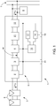
- the photovoltaic inverter 1 has at least one input DC-DC converter 2, an intermediate circuit 3 and an output DC-AC converter 4.
- An energy source 5 is connected to the input DC-DC converter 2, which are preferably formed from one or more solar modules 6 connected in parallel and / or in series with one another.
- the photovoltaic inverter 1 and the solar modules 6 are also referred to as a photovoltaic system or as a PV system.
- the output of the photovoltaic inverter 1 or the output DC-AC converter 4 can be connected to a supply network 7, such as a public or private AC voltage network or a multi-phase network, and / or with at least one electrical consumer 8, which represents a load , be connected.
- a consumer 8 is formed by a motor, refrigerator, radio device, etc.
- the consumer 8 can also represent a domestic supply.
- Such a photovoltaic inverter 1 preferably serves as a so-called grid-connected photovoltaic inverter 1, the energy management of which is optimized to feed as much energy into the supply network 7 as possible.
- the photovoltaic inverter 1 can also serve exclusively to supply loads 8. In this case one speaks of a so-called stand-alone inverter.
- the control device 10 of the photovoltaic inverter 1 is formed, for example, by a microprocessor, microcontroller or computer.
- a corresponding control of the individual components of the photovoltaic inverter 1, such as the input DC-DC converter 2 or the output DC-AC converter 4, in particular the switching elements arranged therein, can be carried out via the control device 10.
- the individual regulating or control sequences are stored in the control device 10 by means of corresponding software programs and / or data or characteristic curves.
- operating elements 11 can be connected to the control device 10 via the data bus 9, by means of which the user can configure the photovoltaic inverter 1 and / or display and set operating states or parameters (for example by means of light-emitting diodes).
- the Operating elements 11 are connected to the control device 10, for example via the data bus 9 or directly.
- Such operating elements 11 are arranged, for example, on a front of the photovoltaic inverter 1, so that operation from the outside is possible.
- the operating elements 11 can also be arranged directly on assemblies and / or modules within the photovoltaic inverter 1.
- auxiliary voltages are applied to the lines of the separation point 12 in a test mode via a control device, which can be formed by the existing control device 10 of the photovoltaic inverter 1, the switching contacts of the separation point 12 are actuated according to a switching pattern and various voltages at the output of the Separation point 12, measured at the separation point 12 and possibly at the input of the separation point 12, from which the individual voltages at the individual switching contacts of the separation point 12 can be back-calculated for each switching pattern and thus the correct functioning of all switching contacts can be determined.
- the voltages are measured against an intermediate circuit potential M of the intermediate circuit 3.
- devices for voltage measurement that are present in any case are preferably used.
- a device 18 serves for the intermediate storage and any averaging of the measured voltages over several periods.
- a warning device 19 can be used to issue a warning to a user or operator of the photovoltaic system in different ways, for example acoustically, visually or the like.
- a line filter 21 can be arranged, which prevents the transmission of impermissible high frequencies via the output AC voltage UAC into the supply network 7 or to the loads 8.
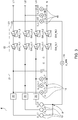
- Fig. 2 the structure of a separation point 12 for four lines Lx, preferably for a three-phase network with three phases L1, L2, L3 and a neutral conductor N is shown.
- each line Lx there are two switching contacts SW_Lx, 1 and SW_Lx, 2 in series.
- All lines Lx of the separation point 12 have inputs E_Lx, in the example shown the inputs E_Li of the phases Li and the input E_N of the neutral conductor N as well as outputs A_Lx, here in particular the outputs A_Li of the phases Li and the output A_N of the neutral conductor N.
- auxiliary voltages U_Lx are applied to the inputs E_Lx of the separation point 12 and, according to a switching pattern, the first switching contacts SW_Lx, 1 of the separation point 12 are alternately closed and the second switching contacts SW_Lx, 2 are opened and then the second switching contacts SW_Lx, 2 closed and the first switch contacts SW_Lx, 1 opened.
- voltages between the output A_Lx of each line Lx of the separation point 12 and the intermediate circuit potential M of the photovoltaic inverter 1 are measured.
- the functionality of each switch contact SW_Lx, j is finally derived from these measured voltages for each switching pattern of the switching contacts SW_Lx, j.
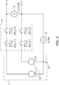
- Fig. 3 the structure of a separation point 12 between a photovoltaic inverter 1 and a supply network 7 or consumer 8 in a three-phase network with three phases L1, L2 and L3 and a neutral conductor using the method according to the invention for checking the separation point 12 is shown.
- auxiliary voltages U_Li are generated by corresponding devices 13, which are impressed between the input E_L1, E_L2, E_L3 of each phase L1, L2, L3 of the separation point 12 and the intermediate circuit potential M in the test mode for testing the switching contacts SW_Li, j and SW_N, j will.
- an auxiliary voltage U_L1 is supplied via a coupling capacitor C between the input E_N of the neutral conductor N of the separation point 12 and the intermediate circuit potential M impressed.
- the voltages U_L1, GD; U_L2, GD; U_L3, GD between the output A_L1; A_L2; A_L3 of each phase L1; L2; L3 of the separation point 12 and the output A_N of the neutral conductor N of the separation point 12 are measured.
- the voltage U_MN between the output A_N of the neutral conductor N of the isolating point 12 and the intermediate circuit potential M is detected via a device 16.
- At least one device 14 for measuring the voltage U_L1, LT between the input E_L1 of phase L1 and the input E_N of the neutral conductor N of the separation point 12 is also provided at the input of the separation point 12.
- the evaluation device 17 the calculation of the voltages at all switch contacts SW_Li, j and SW_N, j takes place to derive the functionality of each switch contact SW_Li, j and SW_N, j from the measured voltages for each switching pattern of the switch contacts SW_Li, j and SW_N, j. It is crucial that sufficient measurement information is available in order to be able to determine the voltages dropping across the switching contacts in order to be able to draw conclusions about their functionality.
- the test of the separation point 12 can be carried out with a single switching operation during the test mode. If the voltage difference at the switch contact is virtually zero, this is an indication that the switch contact is sticking, i.e. not working properly. If the voltage difference at a switch contact essentially corresponds to the impressed auxiliary voltage U_Li, U_N, the corresponding switch contact SW_Li, j or SW_N, j works.
- the following table shows the switching pattern for testing the switching contacts SW_Li, j; SW_N, j of the separation point 12 according to Fig. 3 .
- the total of eight switching contacts are activated according to a switching pattern, which contains two switching states 1 and 2, and the corresponding voltages are measured for each switching state 1 or 2, so that the differential voltages at all switching contacts SW_Lx, j are calculated back and thus sticking of the switching contacts SW_Lx , j can be determined.
Description
Die Erfindung betrifft ein Verfahren zur Prüfung einer Trennstelle eines Photovoltaik-Wechselrichters mit einem Zwischenkreis, wobei die Trennstelle zumindest zwei Leitungen mit jeweils zwei Schaltkontakten in Serie in jeder Leitung aufweist, welche Schaltkontakte zur Prüfung auf Funktionalität entsprechend angesteuert werden.The invention relates to a method for testing a separation point of a photovoltaic inverter with an intermediate circuit, the separation point having at least two lines with two switching contacts in series in each line, which switching contacts are controlled accordingly for testing functionality.
Die Erfindung betrifft weiters einen Photovoltaik-Wechselrichter zur Umwandlung einer Gleichspannung in eine Wechselspannung zur Einspeisung der Wechselspannung in ein Versorgungsnetz und/oder zur Versorgung von Verbrauchern, mit einem Eingangs-DC-DC-Wandler, einem Zwischenkreis, einem Ausgangs-DC-AC-Wandler und einer Trennstelle mit zumindest zwei Leitungen mit jeweils zwei Schaltkontakten in Serie in jeder Leitung.The invention further relates to a photovoltaic inverter for converting a direct voltage into an alternating voltage for feeding the alternating voltage into a supply network and / or for supplying consumers, with an input DC-DC converter, an intermediate circuit, an output DC-AC Converter and a separation point with at least two lines with two switching contacts in series in each line.
Üblicherweise wird als Trennstelle zwischen dem Photovoltaik-Wechselrichter und dem Versorgungsnetz bzw. den Verbrauchern eine Anordnung aus jeweils einem Relaispaar pro Leitung verwendet, um eine sichere Trennung zum Versorgungsnetz bzw. dem Verbraucher zu erreichen. Für die Zulassung zur netzparallelen Einspeisung mit Wechselrichtern ohne galvanische Trennung, ist die Einhaltung einschlägiger Normen und Vorschriften vorausgesetzt. Bspw. ist eine Trennstelle aus zwei voneinander unabhängigen Einrichtungen zur Netzüberwachung mit zugeordneten Schaltern in Serie vorgeschrieben. Die Funktionstüchtigkeit der Schaltstellen ist zu überprüfen, um sicherzustellen, dass vor dem Zuschalten der Relais und vor dem Beginnen eines Einspeisebetriebs ein intakter doppelter Schaltkontaktsatz vorhanden ist und bei Kleben eines einzelnen Schaltkontakts noch alle stromführenden Leiter getrennt werden können.Usually, an arrangement of one relay pair per line is used as the separation point between the photovoltaic inverter and the supply network or the consumers, in order to achieve reliable separation from the supply network or the consumer. Adherence to the relevant standards and regulations is a prerequisite for approval for grid-parallel feed with inverters without galvanic isolation. For example, a separation point from two mutually independent devices for network monitoring with associated switches in series is prescribed. The functionality of the switching points must be checked to ensure that an intact double switch contact set is available before switching on the relays and before starting feed-in operation and that all current-carrying conductors can still be disconnected if a single switch contact is stuck.
Die
Die vorliegende Erfindung ist sowohl bei dreiphasigen Netzen mit drei Phasen und einem Neutralleiter, einphasigen Netzen mit einer Phase und einem Neutralleiter, aber auch dreiphasigen Netzen ohne Neutralleiter oder einphasigen Netzen ohne Neutralleiter wie z.B. dem amerikanischen split-phase-grid oder Einphasendreileiternetz anwendbar.The present invention is applicable to three-phase networks with three phases and a neutral conductor, single-phase networks with one phase and a neutral conductor, but also three-phase networks without a neutral conductor or single-phase networks without a neutral conductor, such as the American split-phase grid or single-phase three-wire network.
Die Aufgabe der vorliegenden Erfindung besteht in der Schaffung eines oben genannten Verfahrens zur Prüfung einer Trennstelle eines Photovoltaik-Wechselrichters und eines solchen Photovoltaik-Wechselrichters, welche einfach und kostengünstig und mit möglichst geringem Hardware-Aufwand realisierbar sind. Die Funktionalität der Trennstelle soll möglichst rasch und mit geringem Messaufwand überprüft werden können. Nachteile bekannter Verfahren sollen vermieden oder zumindest reduziert werden.The object of the present invention is to create an above-mentioned method for testing a separation point of a photovoltaic inverter and such a photovoltaic inverter, which can be implemented simply and inexpensively and with the least possible hardware outlay. The functionality of the separation point should be able to be checked as quickly as possible and with little measurement effort. Disadvantages of known methods should be avoided or at least reduced.
Gelöst wird die erfindungsgemäße Aufgabe in verfahrensmäßiger Hinsicht dadurch, dass in einem Prüfmodus zwischen dem Eingang jeder Leitung der Trennstelle und einem Zwischenkreis-Potential jeweils eine vom Photovoltaik-Wechselrichter erzeugte Hilfsspannung eingeprägt wird, entsprechend einem Schaltmuster abwechselnd jeweils die ersten Schaltkontakte der Trennstelle geschlossen und jeweils die zweiten Schaltkontakte geöffnet und danach jeweils die zweiten Schaltkontakte geschlossen und jeweils die ersten Schaltkontakte geöffnet werden und bei jedem Schaltmuster der Schaltkontakte die Spannungen zwischen dem Ausgang jeder Leitung der Trennstelle und dem Zwischenkreis-Potential gemessen werden und aus den gemessenen Spannungen bei jedem Schaltmuster der Schaltkontakte die Funktionalität jedes Schaltkontakts abgeleitet wird. Erfindungsgemäß wird die Prüfung der Trennstelle im Prüfmodus unter Heranziehung einer vom Photovoltaik-Wechselrichter, insbesondere dessen Ausgangs-DC-AC-Wandler, erzeugten Hilfsspannung vorgenommen, sodass das Verfahren, im Gegensatz zum Stand der Technik, unabhängig vom Anliegen einer bestimmten Netzspannung ist. Dadurch kann das gegenständliche Prüfverfahren auch bei Inselwechselrichtern und auch bei isolierten Netzen und Stromkreisen, einschließlich von Notstromkreisen, in denen vor Zuschalten des Photovoltaik-Wechselrichters auch keine Spannung anliegt, angewendet werden. Dadurch, dass die Hilfsspannung mit vorhandener Hardware des Photovoltaik-Wechselrichters erzeugt wird, ist der Hardware-Aufwand besonders gering, wodurch das Verfahren sehr einfach und kostengünstig durchgeführt werden kann. Im Wesentlichen ist für die Durchführung des Prüfungsmodus ein bestimmter Ablauf nötig, der softwaremäßig in einer vorhandenen Steuervorrichtung des Photovoltaik-Wechselrichters oder in einer eigenen dafür vorgesehenen Steuervorrichtung (bspw. einem Mikroprozessor) relativ einfach implementiert werden kann. Aus den verschiedenen zum Zwischenkreis-Potential gemessenen Spannungen kann bei jedem Schaltmuster die an jedem Schaltkontakt abfallende Spannung berechnet werden und aus diesen berechneten Spannungen auf die Funktionalität der Schaltkontakte und somit das einwandfreie Funktionieren der Trennstelle rückgeschlossen werden. Bei bisherigen Testverfahren, wurde zum Testen der Schaltkontakte die Netzspannung herangezogen. Nachteilig dabei ist, dass bei funktionierenden Schaltkontakten Taktfilterkondensatoren, die parallel zur eingespeisten Netzspannung angeordnet sind, die Netzspannung in den Zwischenkreis einkoppeln und an die Photovoltaikmodule eine 50Hz Spannung überlagert wird. Dadurch kann ein unzulässig hoher Strom über den Zwischenkreis in die parasitäre Kapazität des Solarmoduls fließen und der Fehlerstromschalter kann ausgelöst werden. Das vorliegende Testverfahren erzeugt hingegen im Wesentlichen keine Ableitströme, welche den Fehlerstromschalter auslösen könnten. Da bei Photovoltaik-Wechselrichter für verschiedene Regelungen ohnedies diverse Spannungen vor und nach der Trennstelle gemessen werden, können diese Einrichtungen auch für die Durchführung des Prüfmodus der Trennstelle verwendet werden. Wichtig ist, dass über die eingespeisten Hilfsspannungen Stromkreise gebildet werden, welche einen Rückschluss auf die an jedem Schaltkontakt anliegende Spannung erlauben, um feststellen zu können, ob ein Schaltkontakt in unerwünschter Weise geschlossen ist bzw. klebt. Als Hilfsspannungen kommen vorzugsweise Kleinspannungen zur Anwendung, worunter üblicherweise Spannungen unter 25 V (AC) verstanden werden.In terms of the method, the object according to the invention is achieved in that, in a test mode between the input of each line of the separation point and an intermediate circuit potential, an auxiliary voltage generated by the photovoltaic inverter is impressed, the first switching contacts of the separation point are alternately closed and each time corresponding to a switching pattern the second switch contacts are opened and then the second switch contacts are closed and the first switch contacts are opened and the voltages between the output of each line of the isolating point and the intermediate circuit potential are measured for each switching pattern of the switching contacts and from the measured voltages for each switching pattern of the switching contacts the functionality of each switching contact is derived. According to the invention, the separation point is tested in test mode using an auxiliary voltage generated by the photovoltaic inverter, in particular its output DC-AC converter, so that the method, in contrast to the prior art, is independent of the presence of a specific mains voltage. As a result, the test procedure in question can also be used for stand-alone inverters and also for isolated networks and circuits, including emergency circuits, in which the photovoltaic inverter is switched on also no voltage is applied. Because the auxiliary voltage is generated with the existing hardware of the photovoltaic inverter, the hardware outlay is particularly low, so that the method can be carried out very easily and inexpensively. Essentially, a certain sequence is necessary for the execution of the test mode, which can be implemented relatively easily in software in an existing control device of the photovoltaic inverter or in a dedicated control device (e.g. a microprocessor). From the various voltages measured at the intermediate circuit potential, the voltage drop across each switching contact can be calculated for each switching pattern, and from these calculated voltages, conclusions can be drawn about the functionality of the switching contacts and thus the correct functioning of the isolating point. In previous test procedures, the mains voltage was used to test the switching contacts. The disadvantage here is that with functioning switching contacts, clock filter capacitors, which are arranged parallel to the mains voltage fed in, couple the mains voltage into the intermediate circuit and a 50 Hz voltage is superimposed on the photovoltaic modules. As a result, an impermissibly high current can flow via the intermediate circuit into the parasitic capacitance of the solar module and the fault current switch can be triggered. The present test method, however, essentially does not generate any leakage currents that could trigger the residual current switch. Since various voltages are measured before and after the separation point for various controls in photovoltaic inverters, these devices can also be used to carry out the test mode of the separation point. It is important that circuits are formed via the auxiliary voltages fed in, which allow conclusions to be drawn about the voltage applied to each switching contact in order to be able to determine whether a switching contact is closed or stuck in an undesired manner. Low voltages are preferably used as auxiliary voltages, which are usually understood to mean voltages below 25 V (AC).
Vorteilhafterweise werden abwechselnd alle jeweils ersten Schaltkontakte der Trennstelle gleichzeitig geschlossen und alle jeweils zweiten Schaltkontakte geöffnet und danach alle jeweils zweiten Schaltkontakte gleichzeitig geschlossen und alle jeweils ersten Schaltkontakte geöffnet. Durch das gleichzeitige Schließen und Öffnen der jeweils ersten und jeweils zweiten Schaltkontakte aller Leitungen (Phasen und allenfalls Neutralleiter) der Trennstelle kann das Prüfverfahren besonders rasch und einfach mit einem einmaligen Umschaltvorgang durchgeführt werden.Advantageously, all of the first switching contacts of the separation point are alternately closed at the same time and all of the second switching contacts are opened and then all of them second switching contacts closed at the same time and all first switching contacts opened. By simultaneously closing and opening the respective first and second switching contacts of all lines (phases and possibly the neutral conductor) of the separation point, the test method can be carried out particularly quickly and easily with a single switching process.
Bei einem Photovoltaik-Wechselrichter für ein dreiphasiges Versorgungsnetz mit drei Phasen und einem Neutralleiter werden drei vom Photovoltaik-Wechselrichter erzeugte Hilfsspannungen zwischen dem Eingang jeder Phase der Trennstelle und dem Zwischenkreis-Potential und über einen Koppelkondensator zumindest eine Hilfsspannung zwischen dem Eingang des Neutralleiters der Trennstelle und dem Zwischenkreis-Potential eingeprägt, und die Spannungen zwischen dem Ausgang jeder Phase und dem Ausgang des Neutralleiters der Trennstelle und die Spannung zwischen dem Ausgang des Neutralleiters der Trennstelle und dem Zwischenkreis-Potential sowie zumindest eine Spannung zwischen dem Eingang einer Phase und dem Eingang des Neutralleiters der Trennstelle gemessen, und es wird aus den gemessenen Spannungen bei jedem Schaltmuster der Schaltkontakte die Funktionalität jedes Schaltkontakts abgeleitet. Dies stellt für ein dreiphasiges Netz mit Neutralleiter eine bevorzugte Methode für die Durchführung des Verfahrens zum Prüfen der Teststelle dar. Im einfachsten Fall werden drei Hilfsspannungen an den Eingang der Trennstelle angelegt, wobei zum Testen der beiden Schaltkontakte im Neutralleiter zumindest eine Hilfsspannung über einen Koppelkondensator in den Neutralleiter eingekoppelt wird. In diesem Fall ist während des Prüfmodus der Eingang des Neutralleiters der Trennstelle nicht mit dem Zwischenkreis-Potential verbunden. Durch das Messen der entsprechenden Spannungen am Ausgang der Trennstelle, an der Trennstelle und zumindest einer Spannung am Eingang der Trennstelle können die Spannungen an allen Schaltkontakten der Trennstelle abgeleitet bzw. berechnet werden und auf die Funktionalität der Schaltkontakte der Trennstelle rückgeschlossen werden.In a photovoltaic inverter for a three-phase supply network with three phases and a neutral conductor, three auxiliary voltages generated by the photovoltaic inverter are used between the input of each phase of the separation point and the intermediate circuit potential and, via a coupling capacitor, at least one auxiliary voltage between the input of the neutral conductor of the separation point and impressed on the intermediate circuit potential, and the voltages between the output of each phase and the output of the neutral conductor of the separation point and the voltage between the output of the neutral conductor of the separation point and the intermediate circuit potential and at least one voltage between the input of a phase and the input of the neutral conductor the separation point is measured, and the functionality of each switching contact is derived from the measured voltages for each switching pattern of the switching contacts. For a three-phase network with a neutral conductor, this is a preferred method for carrying out the method for testing the test point. In the simplest case, three auxiliary voltages are applied to the input of the isolating point, with at least one auxiliary voltage via a coupling capacitor in the neutral conductor for testing the two switching contacts the neutral conductor is coupled. In this case, the input of the neutral conductor of the isolating point is not connected to the intermediate circuit potential during the test mode. By measuring the corresponding voltages at the output of the separation point, at the separation point and at least one voltage at the input of the separation point, the voltages at all switching contacts of the separation point can be derived or calculated and conclusions can be drawn about the functionality of the switching contacts of the separation point.
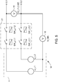
Bei einem Photovoltaik-Wechselrichter für ein einphasiges Versorgungsnetz mit einer Phase und einem Neutralleiter werden zwei vom Photovoltaik-Wechselrichter erzeugte Hilfsspannungen zwischen dem Eingang der Phase der Trennstelle und dem Zwischenkreis-Potential und zwischen dem Eingang des Neutralleiters der Trennstelle und dem Zwischenkreis-Potential eingeprägt, und die Spannung zwischen dem Ausgang der Phase der Trennstelle und dem Ausgang des Neutralleiters der Trennstelle und die Spannung zwischen dem Ausgang des Neutralleiters der Trennstelle und dem Zwischenkreis-Potential gemessen, und aus den gemessenen Spannungen bei jedem Schaltmuster der Schaltkontakte die Funktionalität jedes Schaltkontakts abgeleitet. Dies stellt eine bevorzugte Ausführungsvariante für ein einphasiges Netz mit Neutralleiter dar, bei dem zwei Hilfsspannungen eingeprägt und lediglich zwei Spannungen an geeigneten Stellen nach der Trennstelle und an der Trennstelle gemessen werden, wodurch auf die Funktionalität aller vier Schaltkontakte der Trennstelle rückgeschlossen werden kann.In a photovoltaic inverter for a single-phase supply network with one phase and a neutral conductor, two auxiliary voltages generated by the photovoltaic inverter are between the input of the phase of the separation point and the intermediate circuit potential and between the input of the neutral conductor of the separation point and the intermediate circuit potential, and the voltage between the output of the phase of the separation point and the output of the neutral conductor of the separation point and the voltage between the output of the Measured neutral conductor of the separation point and the intermediate circuit potential, and derived from the measured voltages for each switching pattern of the switching contacts, the functionality of each switching contact. This represents a preferred embodiment variant for a single-phase network with a neutral conductor, in which two auxiliary voltages are impressed and only two voltages are measured at suitable points after the separation point and at the separation point, which allows conclusions to be drawn about the functionality of all four switching contacts of the separation point.
Bei einem Photovoltaik-Wechselrichter für ein einphasiges Versorgungsnetz mit zwei Phasen ohne Neutralleiter, einem sogenannten split-phase-grid werden zwei vom Photovoltaik-Wechselrichter erzeugte Hilfsspannungen zwischen dem Eingang jeder Phase der Trennstelle und dem Zwischenkreis-Potential eingeprägt, und die Spannung zwischen den Ausgängen der Phasen der Trennstelle und die Spannung zwischen dem Ausgang einer Phase der Trennstelle und dem Zwischenkreispotential gemessen, und aus den gemessenen Spannungen bei jedem Schaltmuster der Schaltkontakte die Funktionalität jedes Schaltkontakts abgeleitet. Dieses Verfahren ist ähnlich dem oben beschriebenen Prüfverfahren bei einem einphasigen Netz mit Neutralleiter.In a photovoltaic inverter for a single-phase supply network with two phases without a neutral conductor, a so-called split-phase grid, two auxiliary voltages generated by the photovoltaic inverter are impressed between the input of each phase of the separation point and the intermediate circuit potential, and the voltage between the outputs the phases of the separation point and the voltage between the output of a phase of the separation point and the intermediate circuit potential are measured, and the functionality of each switching contact is derived from the measured voltages for each switching pattern of the switching contacts. This procedure is similar to the test procedure described above for a single-phase network with a neutral conductor.
Wenn im Prüfmodus die verschiedenen Spannungen gleichzeitig gemessen werden, kann das Verfahren besonders rasch und einfach vorgenommen werden. Natürlich sind in diesem Fall mehrere Einrichtungen zur Messung der Spannungen notwendig, welche jedoch üblicherweise in Photovoltaik-Wechselrichtern ohnedies vorhanden sind. Es ist auch denkbar, mit weniger Einrichtungen zur Messung der Spannungen zwischen den Leitungen (Phasen und dem allfälligen Neutralleiter) die Spannungen, welche für die Ableitung der Funktionalität der Schaltkontakte erforderlich sind, auch hintereinander zu messen.If the various voltages are measured simultaneously in the test mode, the procedure can be carried out particularly quickly and easily. In this case, of course, several devices for measuring the voltages are necessary, but these are usually present in photovoltaic inverters anyway. It is also conceivable, with fewer devices for measuring the voltages between the lines (phases and any neutral conductor), to measure the voltages that are required for deriving the functionality of the switching contacts, one after the other.
Die im Prüfmodus gemessenen Spannungen können über mehrere, vorzugsweise 2 bis 20, Perioden gemessen und die Messwerte gemittelt werden. Durch eine Mittelwertbildung mehrerer Messwerte kann das Signal-zu-Rausch-Verhältnis verbessert werden. Die Mittelwertbildung kann unterschiedlich, bspw. durch Bildung eines quadratischen Mittelwerts (RMS, root mean square) erfolgen.The voltages measured in the test mode can be measured over several, preferably 2 to 20, periods and the measured values averaged. The signal-to-noise ratio can be improved by averaging several measured values. The averaging can take place in different ways, for example by forming a root mean square (RMS).
Im Falle der mangelnden Funktionalität eines Schaltkontakts der Trennstelle kann eine Fehlermeldung ausgegeben werden. Die Fehlermeldung kann akustisch, optisch oder auch über ein User Interface fernübertragen werden, um dem Benutzer des Photovoltaik-Wechselrichters in geeigneter Weise rasch einen Fehler der Trennstelle melden zu können.In the case of insufficient functionality of a switching contact of the separation point, an error message can be output. The error message can be transmitted acoustically, visually or remotely via a user interface in order to be able to quickly report an error at the separation point to the user of the photovoltaic inverter in a suitable manner.
Gemäß einem weiteren Merkmal der Erfindung ist vorgesehen, dass im Prüfmodus der Strom in jeder Leitung gemessen wird und bei Überschreitung eines vorgegebenen Grenzwerts eine Strombegrenzung aktiviert wird. Durch die Aktivierung einer solchen Strombegrenzung, welche in vielen Photovoltaik-Wechselrichtern ohnedies vorhanden ist, kann verhindert werden, dass bei ungewolltem gleichzeitigen Schließen beider in Serie geschalteten Schaltkontakte einer Phase oder des Neutralleiters, ein zu hoher Strom fließt, der zu Zerstörungen von Schaltungsteilen führen könnte.According to a further feature of the invention it is provided that in the test mode the current is measured in each line and a current limitation is activated when a predetermined limit value is exceeded. By activating such a current limitation, which is already present in many photovoltaic inverters, it can be prevented that an excessive current flows, which could lead to the destruction of circuit parts, if both switching contacts connected in series of a phase or the neutral conductor are unintentionally closed at the same time .
Vor der Trennstelle kann ein Netzfilter angeordnet werden. Durch ein solches Netzfilter kann eine Übertragung unzulässiger hoher Frequenzen in das Versorgungsnetz bzw. zu den Verbrauchern verhindert werden.A line filter can be placed in front of the separation point. Such a network filter can prevent the transmission of impermissibly high frequencies into the supply network or to the consumers.
Gelöst wird die erfindungsgemäße Aufgabe auch durch einen oben genannten Photovoltaik-Wechselrichter, wobei der Ausgangs-DC-AC-Wandler in einem Prüfmodus zur Prüfung der Schaltkontakte der Trennstelle zur Erzeugung von Hilfsspannungen ausgebildet ist, wobei die Hilfsspannungen zwischen dem Eingang jeder Leitung der Trennstelle und einem Zwischenkreis-Potential einprägbar ist, eine Steuervorrichtung derart ausgebildet ist, dass entsprechend einem Schaltmuster abwechselnd jeweils die ersten Schaltkontakte der Trennstelle geschlossen und jeweils die zweiten Schaltkontakte geöffnet und danach jeweils die zweiten Schaltkontakte geschlossen und alle jeweils ersten Schaltkontakte geöffnet werden, und dass Einrichtungen zur Messung der Spannungen zwischen dem Ausgang jeder Leitung der Trennstelle und dem ZwischenkreisPotential vorgesehen sind und eine Auswerteeinrichtung zur Ableitung der Funktionalität jedes Schaltkontakts aus den gemessenen Spannungen bei jedem Schaltmuster der Schaltkontakte vorgesehen ist. Wie bereits weiter oben erwähnt, zeichnet sich der erfindungsgemäße Photovoltaik-Wechselrichter durch einen besonders geringen Hardware-Aufwand aus. Bezüglich der weiteren dadurch erzielbaren Vorteile wird auf die obige Beschreibung des Prüfverfahrens verwiesen.The object of the invention is also achieved by an above-mentioned photovoltaic inverter, the output DC-AC converter being designed in a test mode for testing the switching contacts of the separation point to generate auxiliary voltages, the auxiliary voltages between the input of each line of the separation point and an intermediate circuit potential can be impressed, a control device is designed in such a way that, in accordance with a switching pattern, the first switching contacts of the isolating point are alternately closed and the second switching contacts are opened and then the second switching contacts are closed and all first switching contacts are opened, and that devices are provided for measuring the voltages between the output of each line of the separation point and the intermediate circuit potential and an evaluation device is provided for deriving the functionality of each switching contact from the measured voltages for each switching pattern of the switching contacts. As already mentioned above, the photovoltaic inverter according to the invention is characterized by a particularly low hardware expenditure. With regard to the further advantages that can be achieved in this way, reference is made to the above description of the test method.
Für ein dreiphasiges Versorgungsnetz mit drei Phasen und einem Neutralleiter ist der Ausgangs-DC-AC-Wandler des Photovoltaik-Wechselrichters zur Erzeugung von drei Hilfsspannungen ausgebildet, wobei die Hilfsspannungen zwischen dem Eingang jeder Phase der Trennstelle und dem Zwischenkreis-Potential und über einen Koppelkondensator zumindest eine Hilfsspannung zwischen dem Eingang des Neutralleiters der Trennstelle und dem ZwischenkreisPotential einprägbar sind, und es sind Einrichtungen zur Messung der Spannungen zwischen dem Ausgang jeder Phase der Trennstelle und eine Einrichtung zur Messung der Spannung zwischen dem Ausgang des Neutralleiters der Trennstelle und dem ZwischenkreisPotential vorgesehen sowie ist zumindest eine Einrichtung zur Messung der Spannung zwischen dem Eingang einer Phase und dem Eingang des Neutralleiters der Trennstelle vorgesehen, und die Auswerteeinrichtung zur Ableitung der Funktionalität jedes Schaltkontakts aus den gemessenen Spannungen bei jedem Schaltmuster der Schaltkontakte ausgebildet.For a three-phase supply network with three phases and a neutral conductor, the output DC-AC converter of the photovoltaic inverter is designed to generate three auxiliary voltages, the auxiliary voltages between the input of each phase of the separation point and the intermediate circuit potential and via a coupling capacitor at least an auxiliary voltage can be impressed between the input of the neutral conductor of the separation point and the intermediate circuit potential, and devices for measuring the voltages between the output of each phase of the separation point and a device for measuring the voltage between the output of the neutral conductor of the separation point and the intermediate circuit potential are provided at least one device for measuring the voltage between the input of a phase and the input of the neutral conductor of the isolating point is provided, and the evaluation device for deriving the functionality of each switching contact from the measured voltages at each switching circuit formed ster of switching contacts.
Wenn der zumindest eine Koppelkondensator durch den Kondensator eines Netzfilters gebildet ist, kann für die Testvorrichtung vorhandene Hardware eingesetzt werden. Durch ein vor der Trennstelle angeordnetes Netzfilter kann eine Übertragung hochfrequenter Signale verhindert werden und es können EMV (Elektromagnetische Verträglichkeit)-Bestimmungen eingehalten werden.If the at least one coupling capacitor is formed by the capacitor of a line filter, existing hardware can be used for the test device. A line filter arranged in front of the separation point can prevent the transmission of high-frequency signals and EMC (electromagnetic compatibility) regulations can be complied with.
Für ein einphasiges Versorgungsnetz mit einer Phase und einem Neutralleiter ist der Ausgangs-DC-AC-Wandler zur Erzeugung von zwei Hilfsspannungen ausgebildet, wobei die Hilfsspannungen zwischen dem Eingang der Phase der Trennstelle und zwischen dem Eingang des Neutralleiters der Trennstelle und dem Zwischenkreis-Potential einprägbar sind, und ist eine Einrichtung zur Messung der Spannungen zwischen dem Ausgang der Phase und dem Ausgang des Neutralleiters der Trennstelle und eine Einrichtung zur Messung der Spannung zwischen dem Ausgang des Neutralleiters der Trennstelle und dem Zwischenkreispotential vorgesehen, und ist die Auswerteeinrichtung zur Ableitung der Funktionalität jedes Schaltkontakts aus den gemessenen Spannungen bei jedem Schaltmuster der Schaltkontakte ausgebildet.For a single-phase supply network with one phase and one neutral conductor, the output DC-AC converter is used to generate formed two auxiliary voltages, the auxiliary voltages between the input of the phase of the separation point and between the input of the neutral conductor of the separation point and the intermediate circuit potential can be impressed, and is a device for measuring the voltages between the output of the phase and the output of the neutral conductor of the separation point and a device for measuring the voltage between the output of the neutral conductor of the separation point and the intermediate circuit potential is provided, and the evaluation device is designed to derive the functionality of each switching contact from the measured voltages for each switching pattern of the switching contacts.
Für ein einphasiges Versorgungsnetz mit zwei Phasen ohne Neutralleiter ist der Ausgangs-DC-AC-Wandler zur Erzeugung von zwei Hilfsspannungen ausgebildet, wobei die Hilfsspannungen zwischen den Eingängen der Phasen der Trennstelle und dem ZwischenkreisPotential einprägbar sind, und ist eine Einrichtung zur Messung der Spannung zwischen den Ausgängen der Phasen der Trennstelle und eine Einrichtung zur Messung der Spannung zwischen dem Ausgang einer Phase der Trennstelle und dem Zwischenkreis-Potential vorgesehen, und ist die Auswerteeinrichtung zur Ableitung der Funktionalität jedes Schaltkontakts aus den gemessenen Spannungen bei jedem Schaltmuster der Schaltkontakte ausgebildet.For a single-phase supply network with two phases without a neutral conductor, the output DC-AC converter is designed to generate two auxiliary voltages, whereby the auxiliary voltages can be impressed between the inputs of the phases of the separation point and the intermediate circuit potential, and is a device for measuring the voltage between the outputs of the phases of the separation point and a device for measuring the voltage between the output of a phase of the separation point and the intermediate circuit potential is provided, and the evaluation device is designed to derive the functionality of each switching contact from the measured voltages for each switching pattern of the switching contacts.
Wenn eine Einrichtung zum Zwischenspeichern und zur Mittelwertbildung der gemessenen Spannungen vor und nach der Trennstelle über mehrere, vorzugsweise 2 bis 20, Perioden vorgesehen ist, kann das Signal-zu-Rausch-Verhältnis verbessert werden.If a device is provided for temporarily storing and averaging the measured voltages before and after the separation point over several, preferably 2 to 20, periods, the signal-to-noise ratio can be improved.
Wenn eine Warneinrichtung zur Ausgabe einer Fehlermeldung im Falle der Erkennung einer mangelnden Funktionalität eines Schaltkontakts der Trennstelle vorgesehen ist, kann der Betreiber des Photovoltaik-Wechselrichters rasch und einfach von einer mangelnden Funktionalität der Trennstelle informiert werden.If a warning device is provided for outputting an error message in the event that a lack of functionality of a switching contact of the separation point is detected, the operator of the photovoltaic inverter can be informed quickly and easily of a lack of functionality of the separation point.
Vorzugsweise ist eine Einrichtung zu Begrenzung des Stromes durch jede Phase im Prüfmodus vorgesehen. Dadurch kann, wie bereits oben im Zusammenhang mit dem Prüfverfahren festgehalten, eine Begrenzung des Stromes bei ungewolltem gleichzeitigem Schließen beider in Serie angeordneter Schaltkontakte erreicht werden.A device is preferably provided for limiting the current through each phase in the test mode. In this way, as already stated above in connection with the test method, a limitation of the current can be achieved in the event of unintentional simultaneous closing of both switching contacts arranged in series will.
Die jeweils ersten Schaltkontakte aller Leitungen können durch zumindest ein mehrpoliges Relais gebildet sind und die jeweils zweiten Schaltkontakte aller Leitungen durch zumindest ein weiteres mehrpoliges Relais gebildet sein. Die Schaltkontakte können somit durch Doppelrelais oder Mehrfachrelais gebildet werden. Im einfachsten Fall werden sämtlich erste Schaltkontakte durch ein mehrpoliges Relais und sämtliche zweite Schaltkontakte durch ein weiteres mehrpoliges Relais gebildet, wodurch nur zwei Relais für die Realisierung der Trennstelle erforderlich sind.The respective first switching contacts of all lines can be formed by at least one multi-pole relay and the respective second switching contacts of all lines can be formed by at least one further multi-pole relay. The switching contacts can thus be formed by double relays or multiple relays. In the simplest case, all of the first switching contacts are formed by a multi-pole relay and all of the second switching contacts by a further multi-pole relay, so that only two relays are required for realizing the separation point.
Die vorliegende Erfindung wird anhand der beigefügten Zeichnungen näher erläutert. Darin zeigen:
- Fig. 1
- ein schematisches Blockschaltbild eines Photovoltaik-Wechselrichters;
- Fig. 2
- den Aufbau einer Trennstelle zwischen einem Photovoltaik-Wechselrichter und einem Versorgungsnetz bzw. Verbraucher bei einem dreiphasigen Netz;
- Fig. 3
- den schematischen Aufbau einer Trennstelle zwischen einem Photovoltaik-Wechselrichter und einem dreiphasigen Versorgungsnetz mit Neutralleiter mit der Anwendung des erfindungsgemäßen Verfahrens zur Überprüfung der Trennstelle;
- Fig. 4
- den schematischen Aufbau einer Trennstelle zwischen einem Photovoltaik-Wechselrichter und einem einphasigen Versorgungsnetz mit Neutralleiter mit der Anwendung des erfindungsgemäßen Verfahrens zur Überprüfung der Trennstelle; und
- Fig. 5
- den schematischen Aufbau einer Trennstelle zwischen einem Photovoltaik-Wechselrichter und einem einphasigen Versorgungsnetz ohne Neutralleiter mit der Anwendung des erfindungsgemäßen Verfahrens zur Überprüfung der Trennstelle.
- Fig. 1
- a schematic block diagram of a photovoltaic inverter;
- Fig. 2
- the construction of a separation point between a photovoltaic inverter and a supply network or consumer in a three-phase network;
- Fig. 3
- the schematic structure of a separation point between a photovoltaic inverter and a three-phase supply network with a neutral conductor with the application of the method according to the invention for checking the separation point;
- Fig. 4
- the schematic structure of a separation point between a photovoltaic inverter and a single-phase supply network with a neutral conductor with the application of the method according to the invention for checking the separation point; and
- Fig. 5
- the schematic structure of a separation point between a photovoltaic inverter and a single-phase supply network without a neutral conductor with the application of the method according to the invention for checking the separation point.
In
Bevorzugt dient ein derartiger Photovoltaik-Wechselrichter 1 als sogenannter netzgekoppelter Photovoltaik-Wechselrichter 1, dessen Energiemanagement daraufhin optimiert ist, möglichst viel Energie in das Versorgungsnetz 7 einzuspeisen. Alternativ dazu kann der Photovoltaik-Wechselrichter 1 auch ausschließlich zur Versorgung von Verbrauchern 8 dienen. In diesem Fall spricht man von einem sogenannten Inselwechselrichter.Such a
Die einzelnen Komponenten des Photovoltaik-Wechselrichters 1, wie der Eingangs-DC-DC-Wandler 2 usw., können über einen Datenbus 9 mit einer Steuervorrichtung 10 verbunden sein. Die Steuervorrichtung 10 des Photovoltaik-Wechselrichters 1 ist beispielsweise durch einen Mikroprozessor, Mikrocontroller oder Rechner gebildet. Über die Steuervorrichtung 10 kann eine entsprechende Steuerung der einzelnen Komponenten des Photovoltaik-Wechselrichters 1, wie dem Eingangs-DC-DC-Wandler 2 oder dem Ausgangs-DC-AC-Wandler 4, insbesondere der darin angeordneten Schaltelemente, vorgenommen werden. In der Steuervorrichtung 10 sind hierzu die einzelnen Regel- bzw. Steuerabläufe durch entsprechende Software-Programme und/oder Daten bzw. Kennlinien gespeichert.The individual components of the
Des Weiteren können über den Datenbus 9 mit der Steuervorrichtung 10 Bedienelemente 11 verbunden sein, durch welche der Benutzer beispielsweise den Photovoltaik-Wechselrichter 1 konfigurieren und/oder Betriebszustände oder Parameter anzeigen (beispielsweise mittels Leuchtdioden) und einstellen kann. Die Bedienelemente 11 sind dabei beispielsweise über den Datenbus 9 oder direkt mit der Steuervorrichtung 10 verbunden. Derartige Bedienelemente 11 sind beispielsweise an einer Front des Photovoltaik-Wechselrichters 1 angeordnet, sodass eine Bedienung von außen möglich ist. Ebenso können die Bedienelemente 11 auch direkt an Baugruppen und/oder Modulen innerhalb des Photovoltaik-Wechselrichters 1 angeordnet sein.Furthermore, operating
Insbesondere bei Verwendung eines Photovoltaik-Wechselrichters 1 zur Einspeisung in ein Versorgungsnetz 7 ist es normativ notwendig, eine Trennstelle 12 zwischen dem Photovoltaik-Wechselrichter 1 und dem Versorgungsnetz 7 zwischenzuschalten. Diese Trennstelle 12 muss vor dem Aufschalten des Photovoltaik-Wechselrichters 1 auf das Versorgungsnetz 7 oder den Verbraucher 8 auf die ordnungsgemäße Funktion überprüft werden. Zu diesem Zweck werden in einem Prüfmodus über eine Steuervorrichtung, welche durch die vorhandene Steuervorrichtung 10 des Photovoltaik-Wechselrichters 1 gebildet sein kann, Hilfsspannungen an die Leitungen der Trennstelle 12 angelegt, die Schaltkontakte der Trennstelle 12 entsprechend einem Schaltmuster betätigt und diverse Spannungen am Ausgang der Trennstelle 12, an der Trennstelle 12 und allenfalls am Eingang der Trennstelle 12 gemessen, aus welchen auf die einzelnen Spannungen an den einzelnen Schaltkontakten der Trennstelle 12 bei jedem Schaltmuster rückgerechnet und dadurch das einwandfreie Funktionieren aller Schaltkontakte festgestellt werden kann. Die Spannungen werden gegenüber einem Zwischenkreis-Potential M des Zwischenkreises 3 gemessen. Zur Messung der Spannungen werden vorzugsweise ohnedies vorhandene Einrichtungen zur Spannungsmessung herangezogen. In einer mit der Steuervorrichtung 10 verbunden Auswerteeinrichtung 17 werden die Spannungen an den einzelnen Schaltkontakten ermittelt und es wird auf die Funktionalität der Schaltkontakte rückgeschlossen. Eine Einrichtung 18 dient dem Zwischenspeichern und allfälligen Mittelwertbildung der gemessenen Spannungen über mehrere Perioden. Über eine Warneinrichtung 19 kann in unterschiedlicher Weise, zum Beispiel akustisch, optisch oder dgl. eine Warnung an einen Benutzer oder Betreiber der Photovoltaikanlage abgegeben werden.In particular when using a
Zwischen dem Ausgangs-DC-AC-Wandler 4 und der Trennstelle 12 kann ein Netzfilter 21 angeordnet sein, welches eine Übertragung unzulässiger hoher Frequenzen über die Ausgangswechselspannung UAC in das Versorgungsnetz 7 bzw. zu den Verbrauchern 8 verhindert.Between the output DC-
In
In
Die folgende Tabelle zeigt das Schaltmuster für die Prüfung der Schaltkontakte SW_Li,j; SW_N,j der Trennstelle 12 gemäß
Die Berechnung der Spannungen an den einzelnen Schaltkontakten SW_Li,j und SW_N,j erfolgt beispielsweise folgendermaßen:
Für die Messung der Spannungen an den Schaltkontakten SW_Li,j der Phasen Li sind die Spannungen U_Li,LT nicht notwendig.
- 1.) Berechnung von der Relaispannung der Phase L1:


- 2.) Berechnung von der Relaisspannung der Phase L2:


- 3.) Berechnung von der Relaisspannung der Phase L3:


- 4.) Berechnung von der Relaisspannung des Neutralleiters N (3 Möglichkeiten):
For the measurement of the voltages at the switch contacts SW_Li, j of the phases Li, the voltages U_Li, LT are not necessary.
- 1.) Calculation of the relay voltage of phase L1:
- 2.) Calculation of the relay voltage of phase L2:
- 3.) Calculation of the relay voltage of phase L3:
- 4.) Calculation of the relay voltage of the neutral conductor N (3 possibilities):
Für die Messung der Spannungen an den Schaltkontakten SW_N,j des Neutralleiters N sind die Spannungen U_Li,GD nach der Trennstelle 12 nicht notwendig. ![]()
![]()
![]()
![]()
![]()
![]()
![]()
![]()
![]()
![]()
![]()
![]()
- 1.) Berechnung der Relaisspannung an Phase L1:


- 2.) Berechnung der Relaisspannung am Neutralleiter N:
Hierfür wird U_L1N,GD nicht benötigt

- 1.) Calculation of the relay voltage at phase L1:
- 2.) Calculation of the relay voltage at the neutral conductor N:
U_L1N, GD is not required for this
- 1.) Berechnung der Relaisspannung an Phase L1:

- 2.) Berechnung der Relaisspannung an Phase L2:
Hierfür wird U_L1L2,GD nicht benötigt.
- 1.) Calculation of the relay voltage at phase L1:
- 2.) Calculation of the relay voltage at phase L2:
U_L1L2, GD is not required for this.
Natürlich sind andere Anordnungen der Spannungsmesseinrichtungen auch denkbar, wobei darauf geachtet werden muss, dass immer entsprechend viele Spannungen gemessen werden, dass eindeutig auf die Spannungen an den einzelnen Schaltkontakten der Trennstelle 12 rückgerechnet werden kann.Of course, other arrangements of the voltage measuring devices are also conceivable, whereby it must be ensured that a corresponding number of voltages are always measured so that the voltages at the individual switching contacts of the
Claims (15)
- Method for testing a disconnection point (12) of a photovoltaic inverter (1) having an intermediate circuit (3), wherein the disconnection point (12) has at least two lines (Lx) each having two switching contacts (SW_Lx,j) in series in each line (Lx), which switching contacts (SW_Lx,j) are controlled accordingly for testing functionality, characterized in that in a testing mode, an auxiliary voltage (U_Lx) generated by the photovoltaic inverter (1) is applied between the input (E_Lx) of each line (Lx) of the disconnection point (12) and an intermediate circuit potential (M) in each case, alternately according to a switching pattern the first switching contacts (SW_Lx,1) of the disconnection point (12) are closed and the second switching contacts (SW_Lx,2) are opened and then the second switching contacts (SW_Lx,2) are closed and the first switching contacts (SW_Lx,1) are opened and, for each switching pattern of the switching contacts (SW_Lx,j), the voltages (U_Lx,GD; U_MN) between the output (A_Lx) of each line (Lx) of the disconnection point (12) and the intermediate circuit potential (M) are measured, and from the measured voltages (U_Lx,GD; U_MN) for each switching pattern of the switching contacts (SW_Lx,j) the functionality of each switching contact (SW_Lx,j) is derived.
- Method according to Claim 1, characterized in that alternately, all the first switching contacts (SW_Lx,1) of the disconnection point (12) are closed simultaneously and all the second switching contacts (SW_Lx,2) are opened and then all the second switching contacts (SW_Lx,2) are closed simultaneously and all the first switching contacts (SW_Lx,1) are opened.
- Method according to Claim 1 or 2, characterized in that in a photovoltaic inverter (1) for a three-phase supply network (7) with three phases (L1, L2, L3) and a neutral conductor (N), three auxiliary voltages (U_L1, U_L2, U_L3) generated by the photovoltaic inverter (1) are applied between the input (E_L1, E_L2, E_L3) of each phase (L1, L2, L3) of the disconnection point (12) and the intermediate circuit potential (M) and at least one auxiliary voltage (U_L1) is applied between the input (E_N) of the neutral conductor (N) of the disconnection point (12) and the intermediate circuit potential (M) via a coupling capacitor (C), and the voltages (U_L1,GD, U_L2,GD, U_L3,GD) between the output (A_L1, A_L2, A L3) of each phase (L1, L2, L3) and the output (A_N) of the neutral conductor (N) of the disconnection point (12) and the voltage (U MN) between the output (A_N) of the neutral conductor (N) of the disconnection point (12) and the intermediate circuit potential (M) as well as at least one voltage (U_Li,LT) between the input (E_Li) of a phase (Li) and the input (E_N) of the neutral conductor (N) of the disconnection point (12) are measured, and from the measured voltages (U_L1,GD, U_L2,GD, U_L3,GD, U_MN, U_Li,LT) for each switching pattern of the switching contacts (SW_Li,j; SW_N,j) the functionality of each switching contact (SW_Li,j; SW_N,j) is derived.
- Method according to Claim 1 or 2, characterized in that in a photovoltaic inverter (1) for a single-phase supply network (7) with one phase (L1) and a neutral conductor (N), two auxiliary voltages (U_L1, U_N) generated by the photovoltaic inverter (1) are applied between the input (E_L1) of the phase (L1) of the disconnection point (12) and the intermediate circuit potential (M) and between the input (E_N) of the neutral conductor (N) of the disconnection point (12) and the intermediate circuit potential (M), and the voltage (U_L1N,GD) between the output (A_L1) of the phase (L1) of the disconnection point (12) and the output (A_N) of the neutral conductor (N) of the disconnection point (12) and the voltage (U MN) between the output (A_N) of the neutral conductor (N) of the disconnection point (12) and the intermediate circuit potential (M) are measured, and from the measured voltages (U_L1N,GD; U_MN) for each switching pattern of the switching contacts (SW_Li,j; SW_N,j) the functionality of each switching contact (SW_Li,j; SW_N,j) is derived.
- Method according to Claim 1 or 2, characterized in that in a photovoltaic inverter (1) for a single-phase supply network (7) with two phases (L1, L2), two auxiliary voltages (U_L1, U_L2) generated by the photovoltaic inverter (1) are applied between the input (E_L1, E_L2) of each phase (L1, L2) of the disconnection point (12) and the intermediate circuit potential (M), and the voltage (U_L1L2,GD) between the outputs (A_L1, A_L2) of the phases (L1, L2) of the disconnection point (12) and the voltage (U_MN) between the output (A_L2) of one phase (L2) of the disconnection point (12) and the intermediate circuit potential (M) are measured, and from the measured voltages (U_L1L2,GD; U_MN) for each switching pattern of the switching contacts (SW_Li,j) the functionality of each switching contact (SW_Li,j) is derived.
- Method according to any one of Claims 1 to 5, characterized in that the voltages (U_Lx,LT; U_Lx,GD; U_MN) measured in the testing mode are measured over a plurality of periods, preferably 2 to 20 periods, and the measured values are averaged.
- Method according to any one of Claims 1 to 6, characterized in that in the testing mode, the current (I Lx) in each line (Lx) is measured and a current limiter is activated when a specified limit value (I_Lx,g) is exceeded.
- Photovoltaic inverter (1) for converting a DC voltage (UDC) into an AC voltage (UAC) for feeding the AC voltage (UAC) into a power supply grid (7) and/or for supplying consumers (8), having an input DC-DC converter (2), an intermediate circuit (3), an output DC-AC converter (4) and a disconnection point (12) with at least two lines (Lx), each with two switching contacts (SW_Lx,j) in series in each line (Lx), characterized in that in a testing mode for testing the switching contacts (SW_Lx,j) of the disconnection point (12) the output DC-AC converter (4) is designed to generate auxiliary voltages (U_Lx), wherein the auxiliary voltages (U_Lx) can be applied between the input (E Lx) of each line (Lx) of the disconnection point (12) and an intermediate circuit potential (M), a control device (10) is designed in such a way that, alternately according to a switching pattern, the first switching contacts (SW_Lx,1) of the disconnection point (12) are closed and the second switching contacts (SW_Lx,2) are opened and then the second switching contacts (SW_Lx,2) are closed and all the first switching contacts (SW_Lx,1) are opened, and that devices (14) for measuring the voltages (U_Lx,GD; U_MN) between the output (A_Lx) of each line (Lx) of the disconnection point (12) and the intermediate circuit potential (M) are provided, and an evaluation device (17) is provided for deriving the functionality of each switching contact (SW_Lx,j) from the measured voltages (U_Lx,LT; U_Lx,GD; U_MN) for each switching pattern of the switching contacts (SW_Lx,j).
- Photovoltaic inverter (1) according to Claim 8, characterized in that for a three-phase supply network (7) with three phases (L1, L2, L3) and a neutral conductor (N) the output DC-AC converter (4) is designed to generate three auxiliary voltages (U_L1, U_L2, U_L3), wherein the auxiliary voltages (U_Li) are applied between the input (E_L1; E L2; E L3) of each phase (L1; L2; L3) of the disconnection point (12) and the intermediate circuit potential (M) and at least one auxiliary voltage (U_L1) can be applied between the input (E_N) of the neutral conductor (N) of the disconnection point (12) and the intermediate circuit potential (M) via a coupling capacitor (C), and that devices (14) are provided for measuring the voltages (U_L1,GD; U_L2,GD; U_L3,GD) between the output (A_L1; A_L2; A_L3) of each phase (L1; L2; L3) of the disconnection point (12) and the output (A_N) of the neutral conductor (N) of the disconnection point (12), a device (16) for measuring the voltage (U_MN) between the output (A_N) of the neutral conductor (N) of the disconnection point (12) and the intermediate circuit potential (M) is provided as well as at least one device (14) for measuring the voltage (U_Li,LT) between the input (E Li) of a phase (Li) and the input (E_N) of the neutral conductor (N) of the disconnection point (12), and that the evaluation device (17) is designed to derive the functionality of each switching contact (SW_Li,j; SW_N,j) from the measured voltages (U_L1,GD; U_L2,GD; U_L3,GD; U_MN; U_L1, LT) for each switching pattern of the switching contacts (SW_Li,j; SW_N,j).
- Photovoltaic inverter (1) according to Claim 9, characterized in that the at least one coupling capacitor (C) is formed by the capacitor (C) of a line filter (21).
- Photovoltaic inverter (1) according to Claim 8, characterized in that for a single-phase supply network (7) with a phase (L1) and a neutral conductor (N) the output DC-AC converter (4) is designed to generate two auxiliary voltages (U_L1, U_N), wherein the auxiliary voltages (U_L1, U_N) can be applied between the input (E_L1) of the phase (L1) of the disconnection point (12) and between the input (E_N) of the neutral conductor (N) of the disconnection point (12) and the intermediate circuit potential (M), and that a device (14) is provided for measuring the voltages (U_L1N,GD) between the output (A_L1) of the phase (L1) and the output (A_N) of the neutral conductor (N) of the disconnection point (12), and a device (16) is provided for measuring the voltage (U MN) between the output (A_N) of the neutral conductor (N) of the disconnection point (12) and the intermediate circuit potential (M), and that the evaluation device (17) is designed to derive the functionality of each switching contact (SW_Li,j; SW_N,j) from the measured voltages (U_L1N,GD; U_MN) for each switching pattern of the switching contacts (SW_Li,j; SW_N,j).
- Photovoltaic inverter (1) according to Claim 8, characterized in that for a single-phase supply network (7) with two phases (L1, L2) of the output DC-AC converter (4) for generating two auxiliary voltages (U_L1, U_L2), wherein the auxiliary voltages (U_L1, U_L2) can be applied between the inputs (E_L1, E_L2) of the phases (L1, L2) of the disconnection point (12) and the DC-link potential (M), and that a device (15) is provided for measuring the voltage (U_L1L2,GD) between the outputs (A_L1, A_L2) of the phases (L1, L2) of the disconnection point (12) and a device (16) is provided for measuring the voltage (U_MN) between the output (A_L2) of a phase (L2) of the disconnection point (12) and the intermediate circuit potential (M), and that the evaluation device (17) is designed for deriving the functionality of each switching contact (SW_Li,j; SW_N,j) from the measured voltages (U_L1L2,GD; U MN) for each switching pattern of the switching contacts (SW_Li,j; SW_N,j).
- Photovoltaic inverter (1) according to any one of Claims 8 to 12, characterized in that a warning device (19) for outputting an error message if a lack of functionality of a switching contact (SW_Lx,j) of the disconnection point (12) is detected.
- Photovoltaic inverter (1) according to any one of Claims 8 to 13, characterized in that a device (20) is provided for limiting the current (I_Lx) through each line (Lx) in the testing mode.
- Photovoltaic inverter (1) according to any one of Claims 8 to 14, characterized in that the first switching contacts (SW_Lx,1) of all lines (Lx) of the disconnection point (12) are formed by at least one multi-pole relay (22) and the second switching contacts (SW_Lx,2) of all lines (Lx) of the disconnection point (12) are formed by at least one further multi-pole relay (23).
Priority Applications (1)
| Application Number | Priority Date | Filing Date | Title |
|---|---|---|---|
| PL19779492T PL3824524T3 (en) | 2018-10-03 | 2019-10-03 | Method for testing a disconnection point of a photovoltaic converter and such a photovoltaic converter |
Applications Claiming Priority (2)
| Application Number | Priority Date | Filing Date | Title |
|---|---|---|---|
| EP18198509.4A EP3633817A1 (en) | 2018-10-03 | 2018-10-03 | Method for testing a disconnection point of a photovoltaic converter and such a photovoltaic converter |
| PCT/EP2019/076788 WO2020070234A1 (en) | 2018-10-03 | 2019-10-03 | Method for testing a disconnection point of a photovoltaic inverter, and a photovoltaic inverter of this type |
Publications (2)
| Publication Number | Publication Date |
|---|---|
| EP3824524A1 EP3824524A1 (en) | 2021-05-26 |
| EP3824524B1 true EP3824524B1 (en) | 2021-12-08 |
Family
ID=63762321
Family Applications (2)
| Application Number | Title | Priority Date | Filing Date |
|---|---|---|---|
| EP18198509.4A Withdrawn EP3633817A1 (en) | 2018-10-03 | 2018-10-03 | Method for testing a disconnection point of a photovoltaic converter and such a photovoltaic converter |
| EP19779492.8A Active EP3824524B1 (en) | 2018-10-03 | 2019-10-03 | Method for testing a disconnection point of a photovoltaic converter and such a photovoltaic converter |
Family Applications Before (1)
| Application Number | Title | Priority Date | Filing Date |
|---|---|---|---|
| EP18198509.4A Withdrawn EP3633817A1 (en) | 2018-10-03 | 2018-10-03 | Method for testing a disconnection point of a photovoltaic converter and such a photovoltaic converter |
Country Status (7)
| Country | Link |
|---|---|
| US (1) | US11125833B1 (en) |
| EP (2) | EP3633817A1 (en) |
| CN (1) | CN112771749B (en) |
| AU (1) | AU2019352740B2 (en) |
| ES (1) | ES2906373T3 (en) |
| PL (1) | PL3824524T3 (en) |
| WO (1) | WO2020070234A1 (en) |
Families Citing this family (1)
| Publication number | Priority date | Publication date | Assignee | Title |
|---|---|---|---|---|
| DK3619783T3 (en) * | 2017-05-05 | 2021-08-30 | Signify Holding Bv | POWER CONVERSION SYSTEM AND METHOD |
Family Cites Families (11)
| Publication number | Priority date | Publication date | Assignee | Title |
|---|---|---|---|---|
| JP3979278B2 (en) * | 2002-11-29 | 2007-09-19 | 松下電工株式会社 | Grid-connected inverter device |
| WO2011153427A2 (en) * | 2010-06-04 | 2011-12-08 | Abb Inc. | Detection of welded switch contacts in a line converter system |
| CN102565691A (en) | 2011-12-14 | 2012-07-11 | 广州三晶电气有限公司 | Relay failure detection device and method for grid-connected inverter |
| DE102011122359A1 (en) * | 2011-12-23 | 2013-06-27 | Kostal Industrie Elektrik Gmbh | Circuit arrangement with an inverter and method for functional testing of electromechanical switches |
| AT512983B1 (en) * | 2012-06-13 | 2014-06-15 | Fronius Int Gmbh | Method for testing a separation point of a photovoltaic inverter and photovoltaic inverter |
| AT513866B1 (en) | 2013-02-14 | 2015-12-15 | Fronius Int Gmbh | Method for testing a separation point of a photovoltaic inverter and photovoltaic inverter |
| DE102013104629A1 (en) * | 2013-05-06 | 2014-11-06 | Refusol Gmbh | Energy generating device with functionally reliable potential separation |
| DE102013110240B4 (en) * | 2013-09-17 | 2017-09-07 | Sma Solar Technology Ag | Circuit arrangement for a photovoltaic inverter for off-load relief with short-circuit switches and uses of the circuit arrangement |
| DE102013113000A1 (en) * | 2013-11-25 | 2015-05-28 | Sma Solar Technology Ag | Method for operating an inverter and inverter with a switch between a mid-point of a DC intermediate circuit and a connection for a neutral conductor of an AC network |
| CN203981841U (en) * | 2014-07-04 | 2014-12-03 | 广东易事特电源股份有限公司 | Single-phase photovoltaic grid-connected inverter auto-cutout device |
| EP3252937A1 (en) * | 2016-06-03 | 2017-12-06 | Fronius International GmbH | Inverter and method for operating an inverter |
-
2018
- 2018-10-03 EP EP18198509.4A patent/EP3633817A1/en not_active Withdrawn
-
2019
- 2019-10-03 US US17/274,245 patent/US11125833B1/en active Active
- 2019-10-03 AU AU2019352740A patent/AU2019352740B2/en active Active
- 2019-10-03 PL PL19779492T patent/PL3824524T3/en unknown
- 2019-10-03 ES ES19779492T patent/ES2906373T3/en active Active
- 2019-10-03 EP EP19779492.8A patent/EP3824524B1/en active Active
- 2019-10-03 WO PCT/EP2019/076788 patent/WO2020070234A1/en unknown
- 2019-10-03 CN CN201980059047.6A patent/CN112771749B/en active Active
Also Published As
| Publication number | Publication date |
|---|---|
| CN112771749A (en) | 2021-05-07 |
| PL3824524T3 (en) | 2022-04-19 |
| BR112021003879A2 (en) | 2021-05-18 |
| CN112771749B (en) | 2021-11-09 |
| WO2020070234A1 (en) | 2020-04-09 |
| AU2019352740B2 (en) | 2021-09-23 |
| ES2906373T3 (en) | 2022-04-18 |
| AU2019352740A1 (en) | 2021-04-01 |
| EP3824524A1 (en) | 2021-05-26 |
| EP3633817A1 (en) | 2020-04-08 |
| US20210311130A1 (en) | 2021-10-07 |
| US11125833B1 (en) | 2021-09-21 |
Similar Documents
| Publication | Publication Date | Title |
|---|---|---|
| DE102011054002B4 (en) | Decentralized power generation plant with device and method for island detection | |
| EP3059828B1 (en) | Device and method for detecting residual curent | |
| EP2994340B1 (en) | Operating method of charging device for single and multiphase charging of energy storage device of vehicle and charging device | |
| EP3391519B1 (en) | Inverter and method for operating an inverter | |
| EP3625863B1 (en) | Localisation of an earth fault in an it network | |
| DE102012104560B4 (en) | Detecting the string configuration for a multi-string inverter | |
| EP2837012B1 (en) | Method for checking a separation point of a photovoltaic inverter, and photovoltaic inverter | |
| EP3254351B9 (en) | Filter monitoring | |
| DE102015114452B4 (en) | Method of operating an inverter and inverter | |
| EP2994767A1 (en) | Energy generation apparatus having functionally reliable electrical isolation | |
| DE102014202426B4 (en) | Method for testing a separation point of a photovoltaic inverter and photovoltaic inverter | |
| EP3824524B1 (en) | Method for testing a disconnection point of a photovoltaic converter and such a photovoltaic converter | |
| EP3696927A1 (en) | Device and method for monitoring a plurality of feeders in a power grid | |
| WO2019007691A1 (en) | Uninterruptible power supply | |
| EP2869072A1 (en) | Device and method for detecting electric energy from single or multiple phase consumers | |
| EP2709226B1 (en) | Circuit arrangement, and level converter and comparator circuit for the circuit arrangement | |
| WO2022112393A1 (en) | Monitoring device for emergency standby operation | |
| EP3629041A1 (en) | Method and arrangement for performing a switch-off test in a transformer | |
| EP2572921A1 (en) | Circuit monitoring |
Legal Events
| Date | Code | Title | Description |
|---|---|---|---|
| STAA | Information on the status of an ep patent application or granted ep patent |
Free format text: STATUS: UNKNOWN |
|
| STAA | Information on the status of an ep patent application or granted ep patent |
Free format text: STATUS: THE INTERNATIONAL PUBLICATION HAS BEEN MADE |
|
| STAA | Information on the status of an ep patent application or granted ep patent |
Free format text: STATUS: THE INTERNATIONAL PUBLICATION HAS BEEN MADE |
|
| PUAI | Public reference made under article 153(3) epc to a published international application that has entered the european phase |
Free format text: ORIGINAL CODE: 0009012 |
|
| STAA | Information on the status of an ep patent application or granted ep patent |
Free format text: STATUS: REQUEST FOR EXAMINATION WAS MADE |
|
| 17P | Request for examination filed |
Effective date: 20210216 |
|
| AK | Designated contracting states |
Kind code of ref document: A1 Designated state(s): AL AT BE BG CH CY CZ DE DK EE ES FI FR GB GR HR HU IE IS IT LI LT LU LV MC MK MT NL NO PL PT RO RS SE SI SK SM TR |
|
| GRAP | Despatch of communication of intention to grant a patent |
Free format text: ORIGINAL CODE: EPIDOSNIGR1 |
|
| STAA | Information on the status of an ep patent application or granted ep patent |
Free format text: STATUS: GRANT OF PATENT IS INTENDED |
|
| INTG | Intention to grant announced |
Effective date: 20210624 |
|
| GRAS | Grant fee paid |
Free format text: ORIGINAL CODE: EPIDOSNIGR3 |
|
| GRAA | (expected) grant |
Free format text: ORIGINAL CODE: 0009210 |
|
| STAA | Information on the status of an ep patent application or granted ep patent |
Free format text: STATUS: THE PATENT HAS BEEN GRANTED |
|
| DAV | Request for validation of the european patent (deleted) | ||
| DAX | Request for extension of the european patent (deleted) | ||
| AK | Designated contracting states |
Kind code of ref document: B1 Designated state(s): AL AT BE BG CH CY CZ DE DK EE ES FI FR GB GR HR HU IE IS IT LI LT LU LV MC MK MT NL NO PL PT RO RS SE SI SK SM TR |
|
| REG | Reference to a national code |
Ref country code: GB Ref legal event code: FG4D Free format text: NOT ENGLISH |
|
| REG | Reference to a national code |
Ref country code: AT Ref legal event code: REF Ref document number: 1454473 Country of ref document: AT Kind code of ref document: T Effective date: 20211215 Ref country code: CH Ref legal event code: EP |
|
| REG | Reference to a national code |
Ref country code: DE Ref legal event code: R096 Ref document number: 502019002972 Country of ref document: DE |
|
| REG | Reference to a national code |
Ref country code: IE Ref legal event code: FG4D Free format text: LANGUAGE OF EP DOCUMENT: GERMAN |
|
| REG | Reference to a national code |
Ref country code: LT Ref legal event code: MG9D |
|
| REG | Reference to a national code |
Ref country code: NL Ref legal event code: MP Effective date: 20211208 |
|
| REG | Reference to a national code |
Ref country code: ES Ref legal event code: FG2A Ref document number: 2906373 Country of ref document: ES Kind code of ref document: T3 Effective date: 20220418 |
|
| PG25 | Lapsed in a contracting state [announced via postgrant information from national office to epo] |
Ref country code: RS Free format text: LAPSE BECAUSE OF FAILURE TO SUBMIT A TRANSLATION OF THE DESCRIPTION OR TO PAY THE FEE WITHIN THE PRESCRIBED TIME-LIMIT Effective date: 20211208 Ref country code: LT Free format text: LAPSE BECAUSE OF FAILURE TO SUBMIT A TRANSLATION OF THE DESCRIPTION OR TO PAY THE FEE WITHIN THE PRESCRIBED TIME-LIMIT Effective date: 20211208 Ref country code: FI Free format text: LAPSE BECAUSE OF FAILURE TO SUBMIT A TRANSLATION OF THE DESCRIPTION OR TO PAY THE FEE WITHIN THE PRESCRIBED TIME-LIMIT Effective date: 20211208 Ref country code: BG Free format text: LAPSE BECAUSE OF FAILURE TO SUBMIT A TRANSLATION OF THE DESCRIPTION OR TO PAY THE FEE WITHIN THE PRESCRIBED TIME-LIMIT Effective date: 20220308 |
|
| PG25 | Lapsed in a contracting state [announced via postgrant information from national office to epo] |
Ref country code: SE Free format text: LAPSE BECAUSE OF FAILURE TO SUBMIT A TRANSLATION OF THE DESCRIPTION OR TO PAY THE FEE WITHIN THE PRESCRIBED TIME-LIMIT Effective date: 20211208 Ref country code: NO Free format text: LAPSE BECAUSE OF FAILURE TO SUBMIT A TRANSLATION OF THE DESCRIPTION OR TO PAY THE FEE WITHIN THE PRESCRIBED TIME-LIMIT Effective date: 20220308 Ref country code: LV Free format text: LAPSE BECAUSE OF FAILURE TO SUBMIT A TRANSLATION OF THE DESCRIPTION OR TO PAY THE FEE WITHIN THE PRESCRIBED TIME-LIMIT Effective date: 20211208 Ref country code: HR Free format text: LAPSE BECAUSE OF FAILURE TO SUBMIT A TRANSLATION OF THE DESCRIPTION OR TO PAY THE FEE WITHIN THE PRESCRIBED TIME-LIMIT Effective date: 20211208 Ref country code: GR Free format text: LAPSE BECAUSE OF FAILURE TO SUBMIT A TRANSLATION OF THE DESCRIPTION OR TO PAY THE FEE WITHIN THE PRESCRIBED TIME-LIMIT Effective date: 20220309 |
|
| PG25 | Lapsed in a contracting state [announced via postgrant information from national office to epo] |
Ref country code: NL Free format text: LAPSE BECAUSE OF FAILURE TO SUBMIT A TRANSLATION OF THE DESCRIPTION OR TO PAY THE FEE WITHIN THE PRESCRIBED TIME-LIMIT Effective date: 20211208 |
|
| PG25 | Lapsed in a contracting state [announced via postgrant information from national office to epo] |
Ref country code: SM Free format text: LAPSE BECAUSE OF FAILURE TO SUBMIT A TRANSLATION OF THE DESCRIPTION OR TO PAY THE FEE WITHIN THE PRESCRIBED TIME-LIMIT Effective date: 20211208 Ref country code: SK Free format text: LAPSE BECAUSE OF FAILURE TO SUBMIT A TRANSLATION OF THE DESCRIPTION OR TO PAY THE FEE WITHIN THE PRESCRIBED TIME-LIMIT Effective date: 20211208 Ref country code: RO Free format text: LAPSE BECAUSE OF FAILURE TO SUBMIT A TRANSLATION OF THE DESCRIPTION OR TO PAY THE FEE WITHIN THE PRESCRIBED TIME-LIMIT Effective date: 20211208 Ref country code: PT Free format text: LAPSE BECAUSE OF FAILURE TO SUBMIT A TRANSLATION OF THE DESCRIPTION OR TO PAY THE FEE WITHIN THE PRESCRIBED TIME-LIMIT Effective date: 20220408 Ref country code: EE Free format text: LAPSE BECAUSE OF FAILURE TO SUBMIT A TRANSLATION OF THE DESCRIPTION OR TO PAY THE FEE WITHIN THE PRESCRIBED TIME-LIMIT Effective date: 20211208 Ref country code: CZ Free format text: LAPSE BECAUSE OF FAILURE TO SUBMIT A TRANSLATION OF THE DESCRIPTION OR TO PAY THE FEE WITHIN THE PRESCRIBED TIME-LIMIT Effective date: 20211208 |
|
| REG | Reference to a national code |
Ref country code: DE Ref legal event code: R097 Ref document number: 502019002972 Country of ref document: DE |
|
| PG25 | Lapsed in a contracting state [announced via postgrant information from national office to epo] |
Ref country code: IS Free format text: LAPSE BECAUSE OF FAILURE TO SUBMIT A TRANSLATION OF THE DESCRIPTION OR TO PAY THE FEE WITHIN THE PRESCRIBED TIME-LIMIT Effective date: 20220408 |
|
| PLBE | No opposition filed within time limit |
Free format text: ORIGINAL CODE: 0009261 |
|
| STAA | Information on the status of an ep patent application or granted ep patent |
Free format text: STATUS: NO OPPOSITION FILED WITHIN TIME LIMIT |
|
| PG25 | Lapsed in a contracting state [announced via postgrant information from national office to epo] |
Ref country code: DK Free format text: LAPSE BECAUSE OF FAILURE TO SUBMIT A TRANSLATION OF THE DESCRIPTION OR TO PAY THE FEE WITHIN THE PRESCRIBED TIME-LIMIT Effective date: 20211208 Ref country code: AL Free format text: LAPSE BECAUSE OF FAILURE TO SUBMIT A TRANSLATION OF THE DESCRIPTION OR TO PAY THE FEE WITHIN THE PRESCRIBED TIME-LIMIT Effective date: 20211208 |
|
| 26N | No opposition filed |
Effective date: 20220909 |
|
| PG25 | Lapsed in a contracting state [announced via postgrant information from national office to epo] |
Ref country code: MC Free format text: LAPSE BECAUSE OF FAILURE TO SUBMIT A TRANSLATION OF THE DESCRIPTION OR TO PAY THE FEE WITHIN THE PRESCRIBED TIME-LIMIT Effective date: 20211208 |
|
| REG | Reference to a national code |
Ref country code: CH Ref legal event code: PL |
|
| P01 | Opt-out of the competence of the unified patent court (upc) registered |
Effective date: 20230516 |
|
| REG | Reference to a national code |
Ref country code: BE Ref legal event code: MM Effective date: 20221031 |
|
| PG25 | Lapsed in a contracting state [announced via postgrant information from national office to epo] |
Ref country code: LU Free format text: LAPSE BECAUSE OF NON-PAYMENT OF DUE FEES Effective date: 20221003 |
|
| PG25 | Lapsed in a contracting state [announced via postgrant information from national office to epo] |
Ref country code: LI Free format text: LAPSE BECAUSE OF NON-PAYMENT OF DUE FEES Effective date: 20221031 Ref country code: CH Free format text: LAPSE BECAUSE OF NON-PAYMENT OF DUE FEES Effective date: 20221031 |
|
| PG25 | Lapsed in a contracting state [announced via postgrant information from national office to epo] |
Ref country code: BE Free format text: LAPSE BECAUSE OF NON-PAYMENT OF DUE FEES Effective date: 20221031 |
|
| PG25 | Lapsed in a contracting state [announced via postgrant information from national office to epo] |
Ref country code: IE Free format text: LAPSE BECAUSE OF NON-PAYMENT OF DUE FEES Effective date: 20221003 |
|
| PGFP | Annual fee paid to national office [announced via postgrant information from national office to epo] |
Ref country code: PL Payment date: 20230921 Year of fee payment: 5 |
|
| REG | Reference to a national code |
Ref country code: DE Ref legal event code: R082 Ref document number: 502019002972 Country of ref document: DE Representative=s name: BRATOVIC, NINO, DR. RER. NAT., DE |
|
| PGFP | Annual fee paid to national office [announced via postgrant information from national office to epo] |
Ref country code: ES Payment date: 20231110 Year of fee payment: 5 |
|
| PGFP | Annual fee paid to national office [announced via postgrant information from national office to epo] |
Ref country code: IT Payment date: 20231024 Year of fee payment: 5 Ref country code: FR Payment date: 20231026 Year of fee payment: 5 Ref country code: DE Payment date: 20231027 Year of fee payment: 5 |