EP3824250B1 - Drehwinkelmesssystem - Google Patents
Drehwinkelmesssystem Download PDFInfo
- Publication number
- EP3824250B1 EP3824250B1 EP19739586.6A EP19739586A EP3824250B1 EP 3824250 B1 EP3824250 B1 EP 3824250B1 EP 19739586 A EP19739586 A EP 19739586A EP 3824250 B1 EP3824250 B1 EP 3824250B1
- Authority
- EP
- European Patent Office
- Prior art keywords
- sensor
- shaft
- unit
- measuring system
- sensor unit
- Prior art date
- Legal status (The legal status is an assumption and is not a legal conclusion. Google has not performed a legal analysis and makes no representation as to the accuracy of the status listed.)
- Active
Links
Images

Classifications
-
- G—PHYSICS
- G01—MEASURING; TESTING
- G01D—MEASURING NOT SPECIALLY ADAPTED FOR A SPECIFIC VARIABLE; ARRANGEMENTS FOR MEASURING TWO OR MORE VARIABLES NOT COVERED IN A SINGLE OTHER SUBCLASS; TARIFF METERING APPARATUS; MEASURING OR TESTING NOT OTHERWISE PROVIDED FOR
- G01D5/00—Mechanical means for transferring the output of a sensing member; Means for converting the output of a sensing member to another variable where the form or nature of the sensing member does not constrain the means for converting; Transducers not specially adapted for a specific variable
- G01D5/12—Mechanical means for transferring the output of a sensing member; Means for converting the output of a sensing member to another variable where the form or nature of the sensing member does not constrain the means for converting; Transducers not specially adapted for a specific variable using electric or magnetic means
- G01D5/14—Mechanical means for transferring the output of a sensing member; Means for converting the output of a sensing member to another variable where the form or nature of the sensing member does not constrain the means for converting; Transducers not specially adapted for a specific variable using electric or magnetic means influencing the magnitude of a current or voltage
- G01D5/142—Mechanical means for transferring the output of a sensing member; Means for converting the output of a sensing member to another variable where the form or nature of the sensing member does not constrain the means for converting; Transducers not specially adapted for a specific variable using electric or magnetic means influencing the magnitude of a current or voltage using Hall-effect devices
- G01D5/145—Mechanical means for transferring the output of a sensing member; Means for converting the output of a sensing member to another variable where the form or nature of the sensing member does not constrain the means for converting; Transducers not specially adapted for a specific variable using electric or magnetic means influencing the magnitude of a current or voltage using Hall-effect devices influenced by the relative movement between the Hall device and magnetic fields
-
- G—PHYSICS
- G01—MEASURING; TESTING
- G01D—MEASURING NOT SPECIALLY ADAPTED FOR A SPECIFIC VARIABLE; ARRANGEMENTS FOR MEASURING TWO OR MORE VARIABLES NOT COVERED IN A SINGLE OTHER SUBCLASS; TARIFF METERING APPARATUS; MEASURING OR TESTING NOT OTHERWISE PROVIDED FOR
- G01D2205/00—Indexing scheme relating to details of means for transferring or converting the output of a sensing member
- G01D2205/20—Detecting rotary movement
- G01D2205/26—Details of encoders or position sensors specially adapted to detect rotation beyond a full turn of 360°, e.g. multi-rotation
Definitions
- the invention relates to a rotation angle measuring system for detecting a rotational movement of a shaft, with a rotor unit which is connected to the shaft in a rotationally fixed manner and radially encloses the shaft and has at least one sensor magnet, a fixed stator unit with a stator board, and a multi-turn sensor unit which is arranged radially spaced from the shaft on the stator board and functionally cooperates with the sensor magnet to detect shaft revolutions, with a Wiegand sensor, at least one Hall sensor and an evaluation unit which is electrically connected to the Wiegand sensor and the Hall sensor.
- angle measuring systems are used to measure the rotary movements of a shaft and are often referred to as angle measuring devices, angle sensors or rotary encoders. Such systems are used in particular to control and monitor electric motors, especially servo motors, in machines, systems or vehicles.
- Contact-free angle measuring systems for example optical or magnetically excited systems, play a special role here, as they have a long service life due to the wear-free sensors.
- a magnet-based angle measuring system for detecting the rotation of a shaft.
- the measuring system comprises a rotating rotor unit on which several sensor magnets are arranged, and a fixed stator unit on which a multi-turn sensor unit is arranged at a radial distance from the shaft, with a Wiegand sensor, a Hall sensor and an evaluation unit.
- the rotor unit is connected to the shaft in a rotationally fixed manner, so that when the shaft rotates, the sensor magnets are moved past the fixed multi-turn sensor unit, with the magnetic field of the sensor magnets being detected by the Wiegand sensor and the Hall sensor of the multi-turn sensor unit.
- a rotation angle measuring system is known in which the rotor unit is arranged at an axial end of the shaft and the multi-turn sensor unit is arranged axially spaced from the shaft on a stator board of the stator unit.
- a rotation angle measuring system is known in which the rotor unit is arranged at an axial end of an additional sensor shaft which is arranged radially adjacent to the shaft to be monitored and is coupled to it via a gear transmission, and the multi-turn sensor unit is arranged axially spaced from the sensor shaft on a stator board of the stator unit.
- the shaft detected by the angle of rotation measuring system can have different designs and can also have different outer diameters.
- the angle of rotation measuring system In order to enable reliable detection of the rotational movement of the shaft, the angle of rotation measuring system must be adapted to the specific shaft geometry. In this case, an exact alignment between the sensor magnet of the rotor unit and the Wiegand sensor as well as the Hall sensor of the multi-turn sensor unit is crucial, so that in the case of a Rotation of the shaft ensures that the magnetic field of the sensor magnet can be reliably detected by the multiturn sensor unit.
- the task is therefore to create an angle measuring system for detecting the rotational movement of a shaft that can be easily adapted to different shaft geometries.
- the multi-turn sensor unit has a separate sensor unit board which is attached to the stator board of the stator unit and on which the Wiegand sensor, the at least one Hall sensor and the evaluation unit are arranged.
- the multi-turn sensor unit is thus designed as an independent module which can be easily positioned and aligned differently on the stator board in order to ensure reliable detection of the magnetic field of the sensor magnet and thus reliable detection of the rotational movement of the shaft depending on the shaft geometry.
- the rotation angle measuring system according to the invention can therefore be easily adapted to different shaft geometries.
- the Wiegand sensor is arranged on a first axial side of the sensor unit board and the Hall sensor is arranged on a second axial side of the sensor unit board opposite the first axial side.
- the Hall sensor is generally arranged on the axial side of the sensor unit board facing the rotor unit, so that the sensor magnet is guided past the Hall sensor at a very small axial distance.
- the sensor magnetic field thus has a large axial magnetic field component so that the sensor magnetic field can be reliably detected by the Hall sensor.
- the Wiegand sensor is generally arranged on the axial side of the sensor unit board facing away from the rotor unit and is thus arranged at a greater distance from the sensor magnet.
- the sensor magnetic field thus has a large transverse magnetic field component at the position of the Wiegand sensor so that the sensor magnetic field can be reliably detected by the Wiegand wire of the Wiegand sensor, which generally extends radially to the shaft and thus in a transverse plane.
- the arrangement of the Wiegand sensor and the Hall sensor on opposite axial sides of the sensor unit board ensures reliable and precise detection of the rotary movement of the shaft.
- the Wiegand sensor and the Hall sensor are arranged laterally, i.e. in the circumferential direction of the shaft, at a distance from one another on the sensor unit board.
- a sensor magnet is therefore located either on the lateral side of the Wiegand sensor facing the Hall sensor or on the lateral side of the Wiegand sensor facing away from the Hall sensor at the time at which its magnetic field is detected by the Wiegand sensor, and thus at a different distance from the Hall sensor.
- the multiturn sensor unit advantageously has an integrated circuit that forms the evaluation unit and the Hall sensor.
- integrated circuits are commercially available and can be easily arranged on the sensor unit board. This enables a cost-effective and reliable angle measuring system.
- the integrated circuit is arranged on the axial side of the sensor unit board facing the rotor unit and the stator board has a recess on the axial side facing away from the rotor unit, into which the integrated circuit with the Hall sensor is at least partially immersed.
- the axial distance between the sensor magnet and the Hall sensor is therefore very small, so that the sensor magnetic field can be reliably detected by the Hall sensor.
- the rotor unit has four sensor magnets evenly distributed around the circumference. This means that the Wiegand sensor can detect half a revolution of the shaft, which enables reliable detection of the rotational movement of the shaft.
- the shaft is a hollow shaft.
- the rotation angle measuring system according to the invention is particularly suitable for detecting the rotational movement of a hollow shaft, where a conventional arrangement of the sensor at an axial end of the shaft is not possible without special precautions.
- a capacitive single-turn sensor unit is advantageously provided for detecting partial shaft rotations, which comprises a first single-turn sensor element connected to the shaft in a rotationally fixed manner and a fixed second single-turn sensor element.
- the capacitive single-turn sensor unit can be easily integrated into the rotation angle measuring system and enables particularly precise detection of the shaft rotational movement.
- the Figure 1 shows a rotation angle measuring system 10 for detecting the rotational movement of a shaft 12.
- the shaft 12 is a hollow shaft that extends essentially in the axial direction and is driven by a drive motor 14 with a static motor housing 16.
- the rotation angle measuring system 10 comprises a rotor unit 18 and a stator unit 20.
- the rotor unit 18 has a rotor plate 22 which radially surrounds the shaft 12 and is attached directly to the shaft 12. The rotor unit 18 is thus connected to the shaft 12 in a rotationally fixed manner.
- Four sensor magnets 24 are arranged on the axial upper side of the rotor plate 22 and are evenly distributed along its circumference.
- the stator unit 20 has a stator plate 26 which radially surrounds the shaft 12. The stator plate 26 is fixedly attached to the static motor housing 16 via a plurality of stator fastening means 28.
- a multi-turn sensor unit 30 is arranged on the axial underside of the stator board 26, radially spaced from the shaft 12.
- the multi-turn sensor unit 30 has a separate sensor unit board 32 on which a Wiegand sensor 34 and an integrated circuit 36 are arranged.
- the sensor unit board 32 is attached to the axial underside of the stator board 26, for example via an adhesive connection or a plug connection.
- the integrated circuit 36 comprises an evaluation unit 38 and a Hall sensor 40, which are electrically connected to one another.
- the evaluation unit 38 is also electrically connected to the Wiegand sensor 34 and is connected in terms of signal technology to a non-volatile data memory (not shown in detail), in which a revolution count value is stored and read out by the evaluation unit 38.
- the integrated circuit 36 also comprises a control logic (not shown in detail) and an energy management (not shown in detail), which enable energy-autonomous operation of the multi-turn sensor unit 30 via the electrical energy obtained from the Wiegand sensor 34.
- the basic functionality of the multi-turn sensor unit 30 can essentially be described as follows: DE 102 59 223 B3 which are explicitly referred to in this context.
- the Wiegand sensor 34 is arranged on a first axial side A1, here the axial underside, of the sensor unit board 32 and is fastened to the sensor unit board 32.
- the integrated circuit 36 is arranged on a second axial side A2, here the axial top side, of the sensor unit board 32 opposite the first axial side A1 and is fastened to the sensor unit board 32.
- the integrated circuit 36 is essentially completely immersed in a corresponding stator board recess 42 which is formed on the axial underside of the stator board 26.
- the multi-turn sensor unit 34 is positioned and aligned in such a way that when the shaft 12 rotates, the magnetic fields of the sensor magnets 24, which rotate with the shaft 12, can be reliably detected by both the Wiegand sensor 34 and the Hall sensor 40.
- the Wiegand sensor 34 and the integrated circuit 36 are laterally arranged at a distance from one another on the sensor unit board 32, so that the Wiegand sensor 34 and the Hall sensor 40 are positioned offset from one another in the circumferential direction.
- a Hall sensor measurement value detected by the Hall sensor 40 is evaluated by the evaluation unit 38.
- the sensor magnet 24 is located at this detection time either on the lateral side of the Wiegand sensor 34 facing the Hall sensor 40 or on the lateral side of the Wiegand sensor 34 facing away from the Hall sensor 40, and thus at a different distance from the Hall sensor 40. This results in different Hall sensor measured values for the detection time depending on the direction of rotation, so that the direction of rotation of the shaft 12 can be easily determined by evaluating the Hall sensor measured value for the detection time.
- the rotation angle measuring system 10 comprises a capacitive single-turn sensor unit (not shown in detail) with a first single-turn sensor element that is arranged on the axial underside of the rotor unit 18 and is thus connected in a rotationally fixed manner to the shaft 12, and with a second sensor element that is fixedly arranged on the axial top side of the stator unit 20.
- the rotation angle measuring system 10 also has a central logic unit (not shown in detail) that is connected in terms of signal technology to the multi-turn sensor unit 34 and the single-turn sensor unit in order to determine both the absolute number of shaft rotations and the current relative rotation angle of the shaft.
- the central logic unit can be formed, for example, by a microcontroller or by a so-called "field programmable gate array" (FPGA).
Landscapes
- Physics & Mathematics (AREA)
- General Physics & Mathematics (AREA)
- Transmission And Conversion Of Sensor Element Output (AREA)
- Measurement Of Length, Angles, Or The Like Using Electric Or Magnetic Means (AREA)
Description
- Die Erfindung betrifft ein Drehwinkelmesssystem zur Erfassung einer Drehbewegung einer Welle, mit einer mit der Welle drehfest verbundenen und die Welle radial umschließenden Rotoreinheit, die mindestens einen Sensormagnet aufweist, einer feststehenden Statoreinheit mit einer Statorplatine, und einer Multiturn-Sensoreinheit, die radial beabstandet zur Welle auf der Statorplatine angeordnet ist und zur Erfassung von Wellenumdrehungen funktional mit dem Sensormagnet zusammenwirkt, mit einem Wiegand-Sensor, mindestens einem Hall-Sensor und einer Auswerteeinheit, die elektrisch mit dem Wiegand-Sensor und dem Hall-Sensor verbunden ist.
- Derartige Drehwinkelmesssysteme dienen zur Messung von Drehbewegungen einer Welle und werden vielfach auch als Winkelmesseinrichtung, Drehwinkelsensor oder Drehgeber bezeichnet. Solche Systeme werden insbesondere zur Steuerung und Überwachung von Elektromotoren, insbesondere Servomotoren, in Maschinen, Anlagen oder Fahrzeugen eingesetzt. Eine besondere Rolle spielen dabei kontaktfreie Drehwinkelmesssysteme, beispielsweise optische oder magnetisch-erregte Systeme, da diese aufgrund der verschleißfreien Sensorik eine lange Lebensdauer haben.
- Aus der
DE 10 2009 019 719 A1 ist beispielsweise ein Magnet-basiertes Drehwinkelmesssystem zur Erfassung der Drehbewegung einer Welle bekannt. Bei Magnet-basierten Drehwinkelmesssystemen wird die Umdrehung der Welle mittels des Messsystems rein magnetisch oder magnetisch-optisch erfasst. Das Messsystem umfasst eine rotierende Rotoreinheit, auf der mehrere Sensormagnete angeordnet sind, und eine feststehende Statoreinheit, auf der radial beabstandet zu der Welle eine Multiturn-Sensoreinheit angeordnet ist, mit einem Wiegand-Sensor, einem Hall-Sensor und einer Auswerteeinheit. Die Rotoreinheit ist drehfest mit der Welle verbunden, sodass bei einer Drehung der Welle die Sensormagnete an der feststehenden Multiturn-Sensoreinheit vorbeibewegt werden, wobei das Magnetfeld der Sensormagnete von dem Wiegand-Sensor und dem Hall-Sensor der Multiturn-Sensoreinheit erfasst wird. - Aus der
DE 10 2009 051 978 A1 ist ein Drehwinkelmesssystem bekannt, bei dem die Rotoreinheit an einem axialen Ende der Welle angeordnet ist und die Multiturn-Sensoreinheit axial beabstandet zu der Welle auf einer Statorplatine der Statoreinheit angeordnet ist. - Aus der
EP 2 159 547 A2 ist ein Drehwinkelmesssystem bekannt, bei dem die Rotoreinheit an einem axialen Ende einer zusätzlichen Sensorwelle angeordnet ist, die radial benachbart zu der zu überwachenden Welle angeordnet und über ein Zahnradgetriebe mit dieser gekoppelt ist, und die Multiturn-Sensoreinheit axial beabstandet zu der Sensorwelle auf einer Statorplatine der Statoreinheit angeordnet ist. - Abhängig vom Anwendungsbereich kann die von dem Drehwinkelmesssystem erfasste Welle unterschiedlich ausgebildet sein und kann insbesondere auch unterschiedliche Außendurchmesser aufweisen. Um eine zuverlässige Erfassung der Drehbewegung der Welle zu ermöglich, muss das Drehwinkelmesssystem an die spezielle Wellengeometrie angepasst werden. Hierbei ist vor allem eine exakte Ausrichtung zwischen dem Sensormagnet der Rotoreinheit und dem Wiegand-Sensor sowie dem Hall-Sensor der Multiturn-Sensoreinheit entscheidend, sodass bei einer Drehung der Welle das Magnetfeld des Sensormagneten zuverlässig von der Multiturn-Sensoreinheit erfassbar ist.
- Es stellt sich daher die Aufgabe, ein Drehwinkelmesssystem zur Erfassung der Drehbewegung einer Welle zu schaffen, das auf einfache Weise an unterschiedliche Wellengeometrien anpassbar ist.
- Diese Aufgabe wird durch ein Drehwinkelmesssystem zur Erfassung der Drehbewegung einer Welle mit den Merkmalen des Hauptanspruchs 1 gelöst.
- Erfindungsgemäß weist die Multiturn-Sensoreinheit eine separate Sensoreinheit-Platine auf, die an der Statorplatine der Statoreinheit befestigt ist und auf der der Wiegand-Sensor, der mindestens eine Hall-Sensor und die Auswerteeinheit angeordnet sind. Die Multiturn-Sensoreinheit ist somit als eigenständiges Modul ausgebildet, das auf einfache Weise unterschiedlich auf der Statorplatine positioniert und ausgerichtet werden kann, um abhängig von der Wellengeometrie eine zuverlässige Erfassung des Magnetfelds des Sensormagneten und somit eine zuverlässige Erfassung der Drehbewegung der Welle sicherzustellen. Das erfindungsgemäße Drehwinkelmesssystem ist folglich auf einfache Weise an verschiedene Wellengeometrien anpassbar.
- Erfindungsgemäß ist der Wiegand-Sensor auf einer ersten axialen Seite der Sensoreinheit-Platine angeordnet und ist der Hall-Sensor auf einer der ersten axialen Seite gegenüberliegenden zweiten axialen Seite der Sensoreinheit-Platine angeordnet. Hierbei ist der Hall-Sensor im Allgemeinen auf der der Rotoreinheit zugewandten axialen Seite der der Sensoreinheit-Platine angeordnet, sodass der Sensormagnet in einem sehr kleinen axialen Abstand an dem Hall-Sensor vorbeigeführt wird. Das Sensormagnetfeld weist somit an der Position des Hall-Sensors eine große axiale Magnetfeld-Komponente auf, sodass das Sensormagnetfeld zuverlässig von dem Hall-Sensor erfassbar ist. Der Wiegand-Sensor ist im Allgemeinen auf der von der Rotoreinheit abgewandten axialen Seite der Sensoreinheit-Platine angeordnet und somit in einem größeren Abstand zu dem Sensormagneten angeordnet. Das Sensormagnetfeld weist somit an der Position des Wiegand-Sensors eine große transversale Magnetfeld-Komponente auf, sodass das Sensormagnetfeld zuverlässig von dem Wiegand-Draht des Wiegand-Sensor erfassbar ist, der sich im Allgemeinen radial zur Welle und somit in einer Transversalebene erstreckt. Durch die Anordnung des Wiegand-Sensors und des Hall-Sensors auf gegenüberliegenden axialen Seiten der Sensoreinheit-Platine ist somit eine zuverlässige und exakte Erfassung der Drehbewegung der Welle sichergestellt.
- Vorzugsweise sind der Wiegand-Sensor und der Hall-Sensor lateral, also in Umfangsrichtung der Welle, beabstandet zueinander auf der Sensoreinheit-Platine angeordnet. In Abhängigkeit von der Drehrichtung der Welle befindet sich ein Sensormagnet folglich zu dem Zeitpunkt, an dem sein Magnetfeld von dem Wiegand-Sensor erfasst wird, entweder auf der dem Hall-Sensor zugewandten lateralen Seite des Wiegand-Sensors oder auf der von dem Hall-Sensor abgewandten lateralen Seite des Wiegand-Sensors, und somit in einem unterschiedlichen Abstand zu dem Hall-Sensor. Hieraus ergeben sich je nach Drehrichtung unterschiedliche Hall-Sensor-Messwerte für diesen Zeitpunkt, sodass durch Auswertung des Hall-Sensor-Messwertes für diesen Zeitpunkt die Drehrichtung der Welle auf einfache Weise bestimmbar ist.
- Vorteilhafterweise weist die Multiturn-Sensoreinheit einen integrierten Schaltkreis auf, durch den die Auswerteeinheit und der Hall-Sensor gebildet sind. Derartige integrierte Schaltkreise sind kommerziell verfügbar und können auf einfache Weise auf der Sensoreinheit-Platine angeordnet werden. Dies ermöglicht ein kostengünstiges und zuverlässiges Drehwinkelmesssystem.
- In einer besonders vorteilhaften Ausführung der Erfindung ist der integrierte Schaltkreis auf der der Rotoreinheit zugewandten axialen Seite der Sensoreinheit-Platine angeordnet und weist die Statorplatine auf der von der Rotoreinheit abgewandten axialen Seite eine Aussparung auf, in die der integrierte Schaltkreis mit dem Hall-Sensor mindestens teilweise eintaucht. Der axiale Abstand zwischen dem Sensormagnet und dem Hall-Sensor ist folglich sehr klein, sodass das Sensormagnetfeld von dem Hall-Sensor zuverlässig erfassbar ist.
- Vorzugsweise weist die Rotoreinheit vier gleichmäßig entlang des Umfangs verteilte Sensormagnete auf. Hierdurch können von dem Wiegand-Sensor bereits halbe Umdrehungen der Welle erfasst werden, wodurch eine zuverlässige Erfassung der Drehbewegung der Welle ermöglicht wird.
- In einer bevorzugten Ausführung der Erfindung ist die Welle eine Hohlwelle. Das erfindungsgemäße Drehwinkelmesssystem ist insbesondere auch für die Erfassung der Drehbewegung einer Hohlwelle geeignet, bei der eine konventionelle Anordnung der Sensorik an einem axialen Ende der Welle nicht ohne besondere Vorkehrungen möglich ist.
- Vorteilhafterweise ist eine kapazitive Singleturn-Sensoreinheit zur Erfassung von Wellen-Teildrehungen vorgesehen, die ein drehfest mit der Welle verbundenes erstes Singleturn-Sensorelement und ein feststehendes zweites Singleturn-Sensorelement umfasst. Die kapazitive Singleturn-Sensoreinheit ist auf einfache Weise in das Drehwinkelmesssystem integrierbar und ermöglicht eine besonders exakte Erfassung der Wellen-Drehbewegung.
- Ein Ausführungsbeispiel eines erfindungsgemäßen Drehwinkelmesssystems wird nachfolgend anhand der beigefügten Figuren beschrieben, wobei
-
Figur 1 einen Längsschnitt eines erfindungsgemäßen Drehwinkelmesssystems zeigt, -
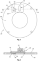
Figur 2 eine Draufsicht auf die axiale Unterseite einer Statorplatine des Drehwinkelmesssystems ausFigur 1 zeigt, auf der eine Multiturn-Sensoreinheit angeordnet ist, -
Figur 3 eine Schnittdarstellung der entlang der Linie III-III geschnittenen Statorplatine und Sensoreinheit ausFigur 2 zeigt, und -
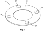
Figur 4 eine perspektivische Darstellung der axialen Oberseite einer Rotoreinheit des Drehwinkelmesssystems ausFigur 1 zeigt. - Die
Figur 1 zeigt ein Drehwinkelmesssystem 10 zur Erfassung der Drehbewegung einer Welle 12. Die Welle 12 ist im vorliegenden Ausführungsbeispiel eine Hohlwelle, die sich im Wesentlichen in axialer Richtung erstreckt und von einem Antriebsmotor 14 mit einem statischen Motorgehäuse 16 angetrieben wird. Das Drehwinkelmesssystem 10 umfasst eine Rotoreinheit 18 und eine Statoreinheit 20. - Die Rotoreinheit 18 weist eine Rotorplatine 22 auf, die die Welle 12 radial umschließt und direkt an der Welle 12 befestigt ist. Die Rotoreinheit 18 ist somit drehfest mit der Welle 12 verbunden. Auf der axialen Oberseite der Rotorplatine 22 sind vier gleichmäßig entlang ihres Umfangs verteilte Sensormagnete 24 angeordnet. Die Statoreinheit 20 weist eine Statorplatine 26 auf, die die Welle 12 radial umschließt. Die Statorplatine 26 ist über mehrere Stator-Befestigungsmittel 28 feststehend an dem statischen Motorgehäuse 16 befestigt.
- Auf der axialen Unterseite der Statorplatine 26 ist radial beabstandet zu der Welle 12 eine Multiturn-Sensoreinheit 30 angeordnet. Die Multiturn-Sensoreinheit 30 weist eine separate Sensoreinheit-Platine 32, auf der ein Wiegand-Sensor 34 und ein integrierter Schaltkreis 36 angeordnet sind. Die Sensoreinheit-Platine 32 ist an der axialen Unterseite der Statorplatine 26 befestigt, beispielsweise über eine Klebeverbindung oder eine Steckverbindung. Der integrierte Schaltkreis 36 umfasst eine Auswerteinheit 38 und einen Hall-Sensor 40, die elektrisch miteinander verbunden sind. Die Auswerteinheit 38 ist ferner elektrisch mit dem Wiegand-Sensor 34 verbunden und ist signaltechnisch mit einem nicht näher gezeigten nicht-flüchtigen Datenspeicher verbunden, in dem ein Umdrehungs-Zählwert von der Auswerteeinheit 38 abgespeichert und ausgelesen wird. Der integrierte Schaltkreis 36 umfasst ferner eine nicht näher dargestellte Steuerlogik und eine nicht näher dargestellte Energieverwaltung, die einen energieautarken Betrieb der Multiturn-Sensoreinheit 30 über die aus dem Wiegand-Sensor 34 gewonnene elektrische Energie ermöglichen. Die grundlegende Funktionsweise der Multiturn-Sensoreinheit 30 kann im Wesentlichen der
DE 102 59 223 B3 entnommen werden, auf die in diesem Zusammenhang explizit verwiesen wird. - Der Wiegand-Sensor 34 ist auf einer ersten axialen Seite A1, hier die axiale Unterseite, der Sensoreinheit-Platine 32 angeordnet und an der Sensoreinheit-Platine 32 befestigt. Der integrierte Schaltkreis 36 auf einer der ersten axialen Seite A1 gegenüberliegenden zweiten axialen Seite A2, hier die axiale Oberseite, der Sensoreinheit-Platine 32 angeordnet und an der Sensoreinheit-Platine 32 befestigt. Der integrierte Schaltkreis 36 taucht im Wesentlichen vollständig in eine korrespondierende Statorplatinen-Aussparung 42 ein, die auf der axialen Unterseite der Statorplatine 26 ausgebildet ist. Die Multiturn-Sensoreinheit 34 ist derart positioniert und ausgerichtet, dass bei einer Rotation der Welle 12 die Magnetfelder der Sensormagnete 24, die mit der Welle 12 mitdrehen, sowohl von dem Wiegand-Sensor 34 als auch von dem Hall-Sensor 40 zuverlässig erfassbar sind. Der Wiegand-Sensor 34 und der integrierte Schaltkreis 36 sind lateral beabstandet zueinander auf der Sensoreinheit-Platine 32 angeordnet, sodass der Wiegand-Sensor 34 und der Hall-Sensor 40 in Umfangsrichtung versetzt zueinander positioniert sind. Sobald der Wiegand-Sensor 34 das Magnetfeld eines Sensormagneten 24 erfasst, wird von der Auswerteeinheit 38 ein von dem Hall-Sensor 40 erfasster Hall-Sensor-Messwert ausgewertet. Abhängig von der Drehrichtung der Welle 12 befindet sich der Sensormagnet 24 zu diesem Erfassungszeitpunkt entweder auf der dem Hall-Sensor 40 zugewandten lateralen Seite des Wiegand-Sensors 34 oder auf der von dem Hall-Sensor 40 abgewandten lateralen Seite des Wiegand-Sensors 34, und somit in einem unterschiedlichen Abstand zu dem Hall-Sensor 40. Hieraus ergeben sich je nach Drehrichtung unterschiedliche Hall-Sensor-Messwerte für den Erfassungszeitpunkt, sodass durch Auswertung des Hall-Sensor-Messwertes für den Erfassungszeitpunkt die Drehrichtung der Welle 12 auf einfache Weise bestimmbar ist.
- Zur Verbesserung der Winkelauflösung umfasst das Drehwinkelmesssystems 10 eine nicht näher dargestellte kapazitive Singleturn-Sensoreinheit mit einem ersten Singleturn-Sensorelement, das an der axialen Unterseite der Rotoreinheit 18 angeordnet ist und somit drehfest mit der Welle 12 verbunden ist, und mit einem zweiten Sensorelement, das feststehend an der axialen Oberseite der Statoreinheit 20 angeordnet ist. Das Drehwinkelmesssystems 10 weist ferner eine nicht näher dargestellte zentrale Logikeinheit auf, die signaltechnisch mit der Multiturn-Sensoreinheit 34 und der Singleturn-Sensoreinheit verbunden ist, um sowohl die absolute Anzahl der Wellendrehungen, als auch den aktuellen relativen Drehwinkelwinkel der Welle zu bestimmen. Die zentrale Logikeinheit kann beispielsweise durch einen Mikrocontroller oder durch ein sogenanntes "Field Programmable Gate Array" (FPGA) gebildet sein.
-
- 10
- Drehwinkelmesssystem
- 12
- Welle
- 14
- Antriebsmotor
- 16
- Motorgehäuse
- 18
- Rotoreinheit
- 20
- Statoreinheit
- 22
- Rotorplatine
- 24
- Sensormagnete
- 26
- Statorplatine
- 28
- Stator-Befestigungsmittel
- 30
- Multiturn-Sensoreinheit
- 32
- Sensoreinheit-Platine
- 34
- Wiegand-Sensor
- 36
- integrierter Schaltkreis
- 38
- Auswerteinheit
- 40
- Hall-Sensor
- 42
- Statorplatinen-Aussparung
- A1
- erste axiale Seite
- A2
- zweite axiale Seite
Claims (7)
- Drehwinkelmesssystem (10) zur Erfassung einer Drehbewegung einer Welle (12), miteiner mit der Welle (12) drehfest verbundenen und die Welle (12) radial umschließenden Rotoreinheit (18), die mindestens einen Sensormagnet (24) aufweist,einer feststehenden Statoreinheit (20) mit einer Statorplatine (26), undeiner Multiturn-Sensoreinheit (30), die radial beabstandet zur Welle (12) auf der Statorplatine (26) angeordnet ist und zur Erfassung von Wellenumdrehungen funktional mit dem Sensormagnet (24) zusammenwirkt, miteinem Wiegand-Sensor (34),mindestens einem Hall-Sensor (40) undeiner Auswerteeinheit (38), die elektrisch mit dem Wiegand-Sensor (34) und dem Hall-Sensor (40) verbunden ist,dadurch gekennzeichnet, dassdie Multiturn-Sensoreinheit (30) eine separate Sensoreinheit-Platine (32) aufweist, die an der Statorplatine (26) befestigt ist und auf der der Wiegand-Sensor (34), der mindestens eine Hall-Sensor (40) und die Auswerteeinheit (38) angeordnet sind, wobei der Wiegand-Sensor (34) auf einer ersten axialen Seite (A1) der Sensoreinheit-Platine (32) angeordnet ist und der Hall-Sensor (40) auf einer der ersten axialen Seite (A1) in axialer Richtunggegenüberliegenden zweiten axialen Seite (A2) der Sensoreinheit-Platine (32) angeordnet ist.
- Drehwinkelmesssystem (10) nach Anspruch 1, wobei der Wiegand-Sensor (34) und der Hall-Sensor (40) lateral beabstandet zueinander auf der Sensoreinheit-Platine (32) angeordnet sind.
- Drehwinkelmesssystem (10) nach einem der vorigen Ansprüche, wobei die Multiturn-Sensoreinheit (30) einen integrierten Schaltkreis (36) aufweist, durch den die Auswerteeinheit (38) und der Hall-Sensor (40) gebildet sind.
- Drehwinkelmesssystem (10) nach Anspruch 3, wobei der integrierte Schaltkreis (36) auf der zweiten axialen Seite (A2) der Sensoreinheit-Platine (32) angeordnet ist und die Statorplatine (26) auf der von der Rotoreinheit (18) abgewandten axialen Seite eine Aussparung (42) aufweist, in die der integrierte Schaltkreis (36) mindestens teilweise eintaucht.
- Drehwinkelmesssystem (10) nach einem der vorigen Ansprüche, wobei die Rotoreinheit (18) vier gleichmäßig entlang des Umfangs verteilte Sensormagnete (24) aufweist.
- Drehwinkelmesssystem (10) nach einem der vorigen Ansprüche, wobei die Welle (12) eine Hohlwelle ist.
- Drehwinkelmesssystem (10) nach einem der vorigen Ansprüche, wobei zusätzlich eine kapazitive Singleturn-Sensoreinheit zur Erfassung von Wellen-Teildrehungen vorhanden ist, die ein drehfest mit der Welle verbundenes erstes Singleturn-Sensorelement und ein feststehendes zweites Singleturn-Sensorelement umfasst.
Applications Claiming Priority (2)
| Application Number | Priority Date | Filing Date | Title |
|---|---|---|---|
| DE102018117600.7A DE102018117600A1 (de) | 2018-07-20 | 2018-07-20 | Drehwinkelmesssystem |
| PCT/EP2019/068690 WO2020016098A1 (de) | 2018-07-20 | 2019-07-11 | Drehwinkelmesssystem |
Publications (2)
| Publication Number | Publication Date |
|---|---|
| EP3824250A1 EP3824250A1 (de) | 2021-05-26 |
| EP3824250B1 true EP3824250B1 (de) | 2024-08-28 |
Family
ID=67262318
Family Applications (1)
| Application Number | Title | Priority Date | Filing Date |
|---|---|---|---|
| EP19739586.6A Active EP3824250B1 (de) | 2018-07-20 | 2019-07-11 | Drehwinkelmesssystem |
Country Status (6)
| Country | Link |
|---|---|
| US (1) | US11460322B2 (de) |
| EP (1) | EP3824250B1 (de) |
| JP (1) | JP7192110B2 (de) |
| CN (1) | CN112513578B (de) |
| DE (1) | DE102018117600A1 (de) |
| WO (1) | WO2020016098A1 (de) |
Families Citing this family (5)
| Publication number | Priority date | Publication date | Assignee | Title |
|---|---|---|---|---|
| EP4320410B1 (de) * | 2021-04-07 | 2025-12-03 | Fraba B.V. | Verfahren zur initialisierung eines drehwinkelmesssystems und drehwinkelmesssystem |
| JP7682031B2 (ja) * | 2021-06-08 | 2025-05-23 | オリエンタルモーター株式会社 | 位置検出器 |
| US20250020685A1 (en) * | 2021-12-03 | 2025-01-16 | Fraba B.V. | Magnet-based detection system for detecting a movement of a movable object |
| EP4658978A1 (de) * | 2024-03-19 | 2025-12-10 | Fraba B.V. | Absolutwert-drehgeber zum erfassen einer drehbewegung einer welle |
| GB2642873A (en) * | 2024-07-23 | 2026-01-28 | Zf Automotive Uk Ltd | Magnetic encoder assembly |
Family Cites Families (14)
| Publication number | Priority date | Publication date | Assignee | Title |
|---|---|---|---|---|
| DE10259223B3 (de) | 2002-11-20 | 2004-02-12 | Mehnert, Walter, Dr. | Positionsdetektor |
| DE102007039051B8 (de) * | 2007-08-17 | 2023-09-28 | Avago Technologies International Sales Pte. Limited | Absoluter feinauflösender Segment- oder Umdrehungszähler |
| DE102007039050B8 (de) * | 2007-08-17 | 2024-02-15 | Avago Technologies International Sales Pte. Limited | Linearsegment- oder Umdrehungszähler mit einem ferromagnetischen Element |
| EP2159547A3 (de) | 2008-08-30 | 2014-06-11 | Walter Mehnert | Sensorbaugruppe für einen Drehgeber und mit einer solchen Sensorbaugruppe ausgestatteter Drehgeber |
| DE102008051083A1 (de) | 2008-10-09 | 2010-04-15 | Dr. Johannes Heidenhain Gmbh | Multiturn-Drehgeber |
| EP2180296A1 (de) | 2008-10-21 | 2010-04-28 | Hella KG Hueck & Co. | Drehwinkelbestimmungsvorrichtung, insbesondere für die Lenkungswelle eines Kraftfahrzeugs |
| DE102009034744A1 (de) | 2009-02-24 | 2010-09-30 | Mehnert, Walter, Dr. | Absoluter magnetischer Positionsgeber |
| DE102009019719A1 (de) | 2009-05-05 | 2010-11-11 | Attosensor Gmbh | Energieautarke magnetische Erfassungsanordnung |
| DE102009051978C5 (de) | 2009-11-04 | 2018-03-08 | Sew-Eurodrive Gmbh & Co Kg | Anordnung zur Winkellageerkennung einer Welle und Elektromotor |
| DE102012002204B4 (de) * | 2012-01-27 | 2019-06-13 | Avago Technologies International Sales Pte. Limited | Magnetfeldsensor |
| KR101987169B1 (ko) | 2012-12-17 | 2019-06-10 | 엘지이노텍 주식회사 | 모터 |
| CN103925933B (zh) | 2013-01-11 | 2016-12-28 | 江苏多维科技有限公司 | 一种多圈绝对磁编码器 |
| EP2965043B1 (de) * | 2013-03-05 | 2018-10-24 | Avago Technologies General IP (Singapore) Pte. Ltd. | Magnetischer linear- oder drehgeber |
| US10759276B2 (en) * | 2016-07-12 | 2020-09-01 | Panasonic Intellectual Property Management Co., Ltd. | Magnetic sensor and detection device using same |
-
2018
- 2018-07-20 DE DE102018117600.7A patent/DE102018117600A1/de active Pending
-
2019
- 2019-07-11 CN CN201980046949.6A patent/CN112513578B/zh active Active
- 2019-07-11 JP JP2021520467A patent/JP7192110B2/ja active Active
- 2019-07-11 WO PCT/EP2019/068690 patent/WO2020016098A1/de not_active Ceased
- 2019-07-11 US US17/261,032 patent/US11460322B2/en active Active
- 2019-07-11 EP EP19739586.6A patent/EP3824250B1/de active Active
Also Published As
| Publication number | Publication date |
|---|---|
| US11460322B2 (en) | 2022-10-04 |
| US20210302201A1 (en) | 2021-09-30 |
| JP2021528667A (ja) | 2021-10-21 |
| DE102018117600A1 (de) | 2020-01-23 |
| WO2020016098A1 (de) | 2020-01-23 |
| CN112513578B (zh) | 2023-06-06 |
| JP7192110B2 (ja) | 2022-12-19 |
| CN112513578A (zh) | 2021-03-16 |
| EP3824250A1 (de) | 2021-05-26 |
Similar Documents
| Publication | Publication Date | Title |
|---|---|---|
| WO2020016098A1 (de) | Drehwinkelmesssystem | |
| EP3775785B1 (de) | Vorrichtung zur bestimmung einer position eines sich bewegenden teils und verfahren zu deren betrieb | |
| EP2748053B1 (de) | Kombinierter lenkmoment-lenkwinkelsensor | |
| EP3824249B1 (de) | Drehwinkelmesssystem | |
| DE102009051978B4 (de) | Anordnung zur Winkellageerkennung einer Welle und Elektromotor | |
| EP3403056B1 (de) | Anordnung eines drehwinkelmesssystems an einem gehäuse | |
| AT4639U1 (de) | Winkelmesseinrichtung | |
| DE102019134949B4 (de) | Ventilvorrichtung | |
| WO2013186001A1 (de) | Magnetgeberring einer rotorlagesensorik eines elektrisch kommutierten elektromotors | |
| DE102013226516A1 (de) | Messanordnung | |
| WO2018121912A1 (de) | Bürstenlose elektrische maschine | |
| EP3400423B2 (de) | Abschirmsystem für magnetisches drehgeber-sensorsystem | |
| EP4320410B1 (de) | Verfahren zur initialisierung eines drehwinkelmesssystems und drehwinkelmesssystem | |
| EP3645980B1 (de) | Verfahren und vorrichtung zur justierung einer position eines magneten zu einem gmr-sensor | |
| EP2524193B1 (de) | Redundante anordnung zur bestimmung der winkellage eines drehbar gelagerten tells | |
| EP2309232B1 (de) | Positionsgeber mit Multiturn-Positionserfassung | |
| EP0902255B1 (de) | Winkelsensor | |
| DE202008018076U1 (de) | Drehwinkelbestimmungsvorrichtung, insbesondere für die Lenkungswelle eines Kraftfahrzeuges | |
| DE102021214471A1 (de) | Rotorwelle und Rotor | |
| DE102018213649A1 (de) | Sensorsystem zur Bestimmung mindestens einer Rotationseigenschaft eines rotierenden Elements | |
| DE102004009839A1 (de) | Drehwinkelsensor | |
| WO2015082512A2 (de) | Hydrodynamische maschine mit messsystem | |
| EP3057850B1 (de) | Sensoranordnung zur erfassung von drehwinkeln an einem rotierenden bauteil in einem fahrzeug | |
| DE202015103893U1 (de) | Anordnung einer Mikrogenerator-Schaltung | |
| EP3128294A2 (de) | Sensor zur bestimmung der winkelposition eines motors sowie ein motor mit einem sensor zur bestimmung der winkelposition |
Legal Events
| Date | Code | Title | Description |
|---|---|---|---|
| STAA | Information on the status of an ep patent application or granted ep patent |
Free format text: STATUS: UNKNOWN |
|
| STAA | Information on the status of an ep patent application or granted ep patent |
Free format text: STATUS: THE INTERNATIONAL PUBLICATION HAS BEEN MADE |
|
| PUAI | Public reference made under article 153(3) epc to a published international application that has entered the european phase |
Free format text: ORIGINAL CODE: 0009012 |
|
| STAA | Information on the status of an ep patent application or granted ep patent |
Free format text: STATUS: REQUEST FOR EXAMINATION WAS MADE |
|
| 17P | Request for examination filed |
Effective date: 20210128 |
|
| AK | Designated contracting states |
Kind code of ref document: A1 Designated state(s): AL AT BE BG CH CY CZ DE DK EE ES FI FR GB GR HR HU IE IS IT LI LT LU LV MC MK MT NL NO PL PT RO RS SE SI SK SM TR |
|
| DAV | Request for validation of the european patent (deleted) | ||
| DAX | Request for extension of the european patent (deleted) | ||
| STAA | Information on the status of an ep patent application or granted ep patent |
Free format text: STATUS: EXAMINATION IS IN PROGRESS |
|
| 17Q | First examination report despatched |
Effective date: 20220922 |
|
| GRAP | Despatch of communication of intention to grant a patent |
Free format text: ORIGINAL CODE: EPIDOSNIGR1 |
|
| STAA | Information on the status of an ep patent application or granted ep patent |
Free format text: STATUS: GRANT OF PATENT IS INTENDED |
|
| INTG | Intention to grant announced |
Effective date: 20240403 |
|
| GRAS | Grant fee paid |
Free format text: ORIGINAL CODE: EPIDOSNIGR3 |
|
| GRAA | (expected) grant |
Free format text: ORIGINAL CODE: 0009210 |
|
| STAA | Information on the status of an ep patent application or granted ep patent |
Free format text: STATUS: THE PATENT HAS BEEN GRANTED |
|
| AK | Designated contracting states |
Kind code of ref document: B1 Designated state(s): AL AT BE BG CH CY CZ DE DK EE ES FI FR GB GR HR HU IE IS IT LI LT LU LV MC MK MT NL NO PL PT RO RS SE SI SK SM TR |
|
| REG | Reference to a national code |
Ref country code: GB Ref legal event code: FG4D Free format text: NOT ENGLISH |
|
| REG | Reference to a national code |
Ref country code: CH Ref legal event code: EP |
|
| REG | Reference to a national code |
Ref country code: DE Ref legal event code: R096 Ref document number: 502019011994 Country of ref document: DE |
|
| REG | Reference to a national code |
Ref country code: IE Ref legal event code: FG4D Free format text: LANGUAGE OF EP DOCUMENT: GERMAN |
|
| REG | Reference to a national code |
Ref country code: LT Ref legal event code: MG9D |
|
| PG25 | Lapsed in a contracting state [announced via postgrant information from national office to epo] |
Ref country code: NO Free format text: LAPSE BECAUSE OF FAILURE TO SUBMIT A TRANSLATION OF THE DESCRIPTION OR TO PAY THE FEE WITHIN THE PRESCRIBED TIME-LIMIT Effective date: 20241128 |
|
| PG25 | Lapsed in a contracting state [announced via postgrant information from national office to epo] |
Ref country code: NL Free format text: LAPSE BECAUSE OF FAILURE TO SUBMIT A TRANSLATION OF THE DESCRIPTION OR TO PAY THE FEE WITHIN THE PRESCRIBED TIME-LIMIT Effective date: 20240828 Ref country code: PL Free format text: LAPSE BECAUSE OF FAILURE TO SUBMIT A TRANSLATION OF THE DESCRIPTION OR TO PAY THE FEE WITHIN THE PRESCRIBED TIME-LIMIT Effective date: 20240828 Ref country code: FI Free format text: LAPSE BECAUSE OF FAILURE TO SUBMIT A TRANSLATION OF THE DESCRIPTION OR TO PAY THE FEE WITHIN THE PRESCRIBED TIME-LIMIT Effective date: 20240828 Ref country code: GR Free format text: LAPSE BECAUSE OF FAILURE TO SUBMIT A TRANSLATION OF THE DESCRIPTION OR TO PAY THE FEE WITHIN THE PRESCRIBED TIME-LIMIT Effective date: 20241129 Ref country code: PT Free format text: LAPSE BECAUSE OF FAILURE TO SUBMIT A TRANSLATION OF THE DESCRIPTION OR TO PAY THE FEE WITHIN THE PRESCRIBED TIME-LIMIT Effective date: 20241230 |
|
| PG25 | Lapsed in a contracting state [announced via postgrant information from national office to epo] |
Ref country code: BG Free format text: LAPSE BECAUSE OF FAILURE TO SUBMIT A TRANSLATION OF THE DESCRIPTION OR TO PAY THE FEE WITHIN THE PRESCRIBED TIME-LIMIT Effective date: 20240828 |
|
| PG25 | Lapsed in a contracting state [announced via postgrant information from national office to epo] |
Ref country code: LV Free format text: LAPSE BECAUSE OF FAILURE TO SUBMIT A TRANSLATION OF THE DESCRIPTION OR TO PAY THE FEE WITHIN THE PRESCRIBED TIME-LIMIT Effective date: 20240828 |
|
| REG | Reference to a national code |
Ref country code: NL Ref legal event code: MP Effective date: 20240828 |
|
| PG25 | Lapsed in a contracting state [announced via postgrant information from national office to epo] |
Ref country code: IS Free format text: LAPSE BECAUSE OF FAILURE TO SUBMIT A TRANSLATION OF THE DESCRIPTION OR TO PAY THE FEE WITHIN THE PRESCRIBED TIME-LIMIT Effective date: 20241228 |
|
| PG25 | Lapsed in a contracting state [announced via postgrant information from national office to epo] |
Ref country code: HR Free format text: LAPSE BECAUSE OF FAILURE TO SUBMIT A TRANSLATION OF THE DESCRIPTION OR TO PAY THE FEE WITHIN THE PRESCRIBED TIME-LIMIT Effective date: 20240828 |
|
| PG25 | Lapsed in a contracting state [announced via postgrant information from national office to epo] |
Ref country code: RS Free format text: LAPSE BECAUSE OF FAILURE TO SUBMIT A TRANSLATION OF THE DESCRIPTION OR TO PAY THE FEE WITHIN THE PRESCRIBED TIME-LIMIT Effective date: 20241128 Ref country code: ES Free format text: LAPSE BECAUSE OF FAILURE TO SUBMIT A TRANSLATION OF THE DESCRIPTION OR TO PAY THE FEE WITHIN THE PRESCRIBED TIME-LIMIT Effective date: 20240828 |
|
| PG25 | Lapsed in a contracting state [announced via postgrant information from national office to epo] |
Ref country code: RS Free format text: LAPSE BECAUSE OF FAILURE TO SUBMIT A TRANSLATION OF THE DESCRIPTION OR TO PAY THE FEE WITHIN THE PRESCRIBED TIME-LIMIT Effective date: 20241128 Ref country code: PT Free format text: LAPSE BECAUSE OF FAILURE TO SUBMIT A TRANSLATION OF THE DESCRIPTION OR TO PAY THE FEE WITHIN THE PRESCRIBED TIME-LIMIT Effective date: 20241230 Ref country code: PL Free format text: LAPSE BECAUSE OF FAILURE TO SUBMIT A TRANSLATION OF THE DESCRIPTION OR TO PAY THE FEE WITHIN THE PRESCRIBED TIME-LIMIT Effective date: 20240828 Ref country code: NO Free format text: LAPSE BECAUSE OF FAILURE TO SUBMIT A TRANSLATION OF THE DESCRIPTION OR TO PAY THE FEE WITHIN THE PRESCRIBED TIME-LIMIT Effective date: 20241128 Ref country code: NL Free format text: LAPSE BECAUSE OF FAILURE TO SUBMIT A TRANSLATION OF THE DESCRIPTION OR TO PAY THE FEE WITHIN THE PRESCRIBED TIME-LIMIT Effective date: 20240828 Ref country code: LV Free format text: LAPSE BECAUSE OF FAILURE TO SUBMIT A TRANSLATION OF THE DESCRIPTION OR TO PAY THE FEE WITHIN THE PRESCRIBED TIME-LIMIT Effective date: 20240828 Ref country code: IS Free format text: LAPSE BECAUSE OF FAILURE TO SUBMIT A TRANSLATION OF THE DESCRIPTION OR TO PAY THE FEE WITHIN THE PRESCRIBED TIME-LIMIT Effective date: 20241228 Ref country code: HR Free format text: LAPSE BECAUSE OF FAILURE TO SUBMIT A TRANSLATION OF THE DESCRIPTION OR TO PAY THE FEE WITHIN THE PRESCRIBED TIME-LIMIT Effective date: 20240828 Ref country code: GR Free format text: LAPSE BECAUSE OF FAILURE TO SUBMIT A TRANSLATION OF THE DESCRIPTION OR TO PAY THE FEE WITHIN THE PRESCRIBED TIME-LIMIT Effective date: 20241129 Ref country code: FI Free format text: LAPSE BECAUSE OF FAILURE TO SUBMIT A TRANSLATION OF THE DESCRIPTION OR TO PAY THE FEE WITHIN THE PRESCRIBED TIME-LIMIT Effective date: 20240828 Ref country code: ES Free format text: LAPSE BECAUSE OF FAILURE TO SUBMIT A TRANSLATION OF THE DESCRIPTION OR TO PAY THE FEE WITHIN THE PRESCRIBED TIME-LIMIT Effective date: 20240828 Ref country code: BG Free format text: LAPSE BECAUSE OF FAILURE TO SUBMIT A TRANSLATION OF THE DESCRIPTION OR TO PAY THE FEE WITHIN THE PRESCRIBED TIME-LIMIT Effective date: 20240828 |
|
| PG25 | Lapsed in a contracting state [announced via postgrant information from national office to epo] |
Ref country code: RO Free format text: LAPSE BECAUSE OF FAILURE TO SUBMIT A TRANSLATION OF THE DESCRIPTION OR TO PAY THE FEE WITHIN THE PRESCRIBED TIME-LIMIT Effective date: 20240828 Ref country code: SM Free format text: LAPSE BECAUSE OF FAILURE TO SUBMIT A TRANSLATION OF THE DESCRIPTION OR TO PAY THE FEE WITHIN THE PRESCRIBED TIME-LIMIT Effective date: 20240828 Ref country code: DK Free format text: LAPSE BECAUSE OF FAILURE TO SUBMIT A TRANSLATION OF THE DESCRIPTION OR TO PAY THE FEE WITHIN THE PRESCRIBED TIME-LIMIT Effective date: 20240828 |
|
| PG25 | Lapsed in a contracting state [announced via postgrant information from national office to epo] |
Ref country code: EE Free format text: LAPSE BECAUSE OF FAILURE TO SUBMIT A TRANSLATION OF THE DESCRIPTION OR TO PAY THE FEE WITHIN THE PRESCRIBED TIME-LIMIT Effective date: 20240828 |
|
| PG25 | Lapsed in a contracting state [announced via postgrant information from national office to epo] |
Ref country code: CZ Free format text: LAPSE BECAUSE OF FAILURE TO SUBMIT A TRANSLATION OF THE DESCRIPTION OR TO PAY THE FEE WITHIN THE PRESCRIBED TIME-LIMIT Effective date: 20240828 |
|
| PG25 | Lapsed in a contracting state [announced via postgrant information from national office to epo] |
Ref country code: IT Free format text: LAPSE BECAUSE OF FAILURE TO SUBMIT A TRANSLATION OF THE DESCRIPTION OR TO PAY THE FEE WITHIN THE PRESCRIBED TIME-LIMIT Effective date: 20240828 Ref country code: SK Free format text: LAPSE BECAUSE OF FAILURE TO SUBMIT A TRANSLATION OF THE DESCRIPTION OR TO PAY THE FEE WITHIN THE PRESCRIBED TIME-LIMIT Effective date: 20240828 |
|
| REG | Reference to a national code |
Ref country code: DE Ref legal event code: R097 Ref document number: 502019011994 Country of ref document: DE |
|
| PLBE | No opposition filed within time limit |
Free format text: ORIGINAL CODE: 0009261 |
|
| STAA | Information on the status of an ep patent application or granted ep patent |
Free format text: STATUS: NO OPPOSITION FILED WITHIN TIME LIMIT |
|
| 26N | No opposition filed |
Effective date: 20250530 |
|
| PG25 | Lapsed in a contracting state [announced via postgrant information from national office to epo] |
Ref country code: SE Free format text: LAPSE BECAUSE OF FAILURE TO SUBMIT A TRANSLATION OF THE DESCRIPTION OR TO PAY THE FEE WITHIN THE PRESCRIBED TIME-LIMIT Effective date: 20240828 |
|
| PGFP | Annual fee paid to national office [announced via postgrant information from national office to epo] |
Ref country code: DE Payment date: 20250722 Year of fee payment: 7 |
|
| PGFP | Annual fee paid to national office [announced via postgrant information from national office to epo] |
Ref country code: GB Payment date: 20250724 Year of fee payment: 7 |
|
| PGFP | Annual fee paid to national office [announced via postgrant information from national office to epo] |
Ref country code: FR Payment date: 20250723 Year of fee payment: 7 |
|
| REG | Reference to a national code |
Ref country code: CH Ref legal event code: H13 Free format text: ST27 STATUS EVENT CODE: U-0-0-H10-H13 (AS PROVIDED BY THE NATIONAL OFFICE) Effective date: 20260224 |
|
| PG25 | Lapsed in a contracting state [announced via postgrant information from national office to epo] |
Ref country code: LU Free format text: LAPSE BECAUSE OF NON-PAYMENT OF DUE FEES Effective date: 20250711 |
|
| REG | Reference to a national code |
Ref country code: BE Ref legal event code: MM Effective date: 20250731 |
|
| PG25 | Lapsed in a contracting state [announced via postgrant information from national office to epo] |
Ref country code: BE Free format text: LAPSE BECAUSE OF NON-PAYMENT OF DUE FEES Effective date: 20250731 |
|
| PG25 | Lapsed in a contracting state [announced via postgrant information from national office to epo] |
Ref country code: CH Free format text: LAPSE BECAUSE OF NON-PAYMENT OF DUE FEES Effective date: 20250731 |