EP3824226B1 - Electric heater for tank - Google Patents
Electric heater for tank Download PDFInfo
- Publication number
- EP3824226B1 EP3824226B1 EP19762858.9A EP19762858A EP3824226B1 EP 3824226 B1 EP3824226 B1 EP 3824226B1 EP 19762858 A EP19762858 A EP 19762858A EP 3824226 B1 EP3824226 B1 EP 3824226B1
- Authority
- EP
- European Patent Office
- Prior art keywords
- wall
- electric heater
- stretch
- tank
- axis
- Prior art date
- Legal status (The legal status is an assumption and is not a legal conclusion. Google has not performed a legal analysis and makes no representation as to the accuracy of the status listed.)
- Active
Links
Images

Classifications
-
- F—MECHANICAL ENGINEERING; LIGHTING; HEATING; WEAPONS; BLASTING
- F24—HEATING; RANGES; VENTILATING
- F24H—FLUID HEATERS, e.g. WATER OR AIR HEATERS, HAVING HEAT-GENERATING MEANS, e.g. HEAT PUMPS, IN GENERAL
- F24H1/00—Water heaters, e.g. boilers, continuous-flow heaters or water-storage heaters
- F24H1/18—Water-storage heaters
- F24H1/20—Water-storage heaters with immersed heating elements, e.g. electric elements or furnace tubes
- F24H1/201—Water-storage heaters with immersed heating elements, e.g. electric elements or furnace tubes using electric energy supply
- F24H1/202—Water-storage heaters with immersed heating elements, e.g. electric elements or furnace tubes using electric energy supply with resistances
-
- F—MECHANICAL ENGINEERING; LIGHTING; HEATING; WEAPONS; BLASTING
- F24—HEATING; RANGES; VENTILATING
- F24H—FLUID HEATERS, e.g. WATER OR AIR HEATERS, HAVING HEAT-GENERATING MEANS, e.g. HEAT PUMPS, IN GENERAL
- F24H1/00—Water heaters, e.g. boilers, continuous-flow heaters or water-storage heaters
- F24H1/10—Continuous-flow heaters, i.e. heaters in which heat is generated only while the water is flowing, e.g. with direct contact of the water with the heating medium
- F24H1/12—Continuous-flow heaters, i.e. heaters in which heat is generated only while the water is flowing, e.g. with direct contact of the water with the heating medium in which the water is kept separate from the heating medium
- F24H1/121—Continuous-flow heaters, i.e. heaters in which heat is generated only while the water is flowing, e.g. with direct contact of the water with the heating medium in which the water is kept separate from the heating medium using electric energy supply
- F24H1/122—Continuous-flow heaters, i.e. heaters in which heat is generated only while the water is flowing, e.g. with direct contact of the water with the heating medium in which the water is kept separate from the heating medium using electric energy supply combined with storage tank
-
- F—MECHANICAL ENGINEERING; LIGHTING; HEATING; WEAPONS; BLASTING
- F01—MACHINES OR ENGINES IN GENERAL; ENGINE PLANTS IN GENERAL; STEAM ENGINES
- F01N—GAS-FLOW SILENCERS OR EXHAUST APPARATUS FOR MACHINES OR ENGINES IN GENERAL; GAS-FLOW SILENCERS OR EXHAUST APPARATUS FOR INTERNAL-COMBUSTION ENGINES
- F01N3/00—Exhaust or silencing apparatus having means for purifying, rendering innocuous, or otherwise treating exhaust
- F01N3/08—Exhaust or silencing apparatus having means for purifying, rendering innocuous, or otherwise treating exhaust for rendering innocuous
- F01N3/10—Exhaust or silencing apparatus having means for purifying, rendering innocuous, or otherwise treating exhaust for rendering innocuous by thermal or catalytic conversion of noxious components of exhaust
- F01N3/18—Exhaust or silencing apparatus having means for purifying, rendering innocuous, or otherwise treating exhaust for rendering innocuous by thermal or catalytic conversion of noxious components of exhaust characterised by methods of operation; Control
- F01N3/20—Exhaust or silencing apparatus having means for purifying, rendering innocuous, or otherwise treating exhaust for rendering innocuous by thermal or catalytic conversion of noxious components of exhaust characterised by methods of operation; Control specially adapted for catalytic conversion
- F01N3/206—Adding periodically or continuously substances to exhaust gases for promoting purification, e.g. catalytic material in liquid form, NOx reducing agents
- F01N3/2066—Selective catalytic reduction [SCR]
-
- F—MECHANICAL ENGINEERING; LIGHTING; HEATING; WEAPONS; BLASTING
- F24—HEATING; RANGES; VENTILATING
- F24H—FLUID HEATERS, e.g. WATER OR AIR HEATERS, HAVING HEAT-GENERATING MEANS, e.g. HEAT PUMPS, IN GENERAL
- F24H1/00—Water heaters, e.g. boilers, continuous-flow heaters or water-storage heaters
- F24H1/10—Continuous-flow heaters, i.e. heaters in which heat is generated only while the water is flowing, e.g. with direct contact of the water with the heating medium
- F24H1/101—Continuous-flow heaters, i.e. heaters in which heat is generated only while the water is flowing, e.g. with direct contact of the water with the heating medium using electric energy supply
- F24H1/102—Continuous-flow heaters, i.e. heaters in which heat is generated only while the water is flowing, e.g. with direct contact of the water with the heating medium using electric energy supply with resistance
-
- H—ELECTRICITY
- H05—ELECTRIC TECHNIQUES NOT OTHERWISE PROVIDED FOR
- H05B—ELECTRIC HEATING; ELECTRIC LIGHT SOURCES NOT OTHERWISE PROVIDED FOR; CIRCUIT ARRANGEMENTS FOR ELECTRIC LIGHT SOURCES, IN GENERAL
- H05B1/00—Details of electric heating devices
- H05B1/02—Automatic switching arrangements specially adapted to apparatus ; Control of heating devices
- H05B1/0227—Applications
- H05B1/023—Industrial applications
- H05B1/0236—Industrial applications for vehicles
-
- H—ELECTRICITY
- H05—ELECTRIC TECHNIQUES NOT OTHERWISE PROVIDED FOR
- H05B—ELECTRIC HEATING; ELECTRIC LIGHT SOURCES NOT OTHERWISE PROVIDED FOR; CIRCUIT ARRANGEMENTS FOR ELECTRIC LIGHT SOURCES, IN GENERAL
- H05B1/00—Details of electric heating devices
- H05B1/02—Automatic switching arrangements specially adapted to apparatus ; Control of heating devices
- H05B1/0227—Applications
- H05B1/023—Industrial applications
- H05B1/0244—Heating of fluids
-
- H—ELECTRICITY
- H05—ELECTRIC TECHNIQUES NOT OTHERWISE PROVIDED FOR
- H05B—ELECTRIC HEATING; ELECTRIC LIGHT SOURCES NOT OTHERWISE PROVIDED FOR; CIRCUIT ARRANGEMENTS FOR ELECTRIC LIGHT SOURCES, IN GENERAL
- H05B3/00—Ohmic-resistance heating
- H05B3/78—Heating arrangements specially adapted for immersion heating
- H05B3/82—Fixedly-mounted immersion heaters
-
- F—MECHANICAL ENGINEERING; LIGHTING; HEATING; WEAPONS; BLASTING
- F01—MACHINES OR ENGINES IN GENERAL; ENGINE PLANTS IN GENERAL; STEAM ENGINES
- F01N—GAS-FLOW SILENCERS OR EXHAUST APPARATUS FOR MACHINES OR ENGINES IN GENERAL; GAS-FLOW SILENCERS OR EXHAUST APPARATUS FOR INTERNAL-COMBUSTION ENGINES
- F01N2240/00—Combination or association of two or more different exhaust treating devices, or of at least one such device with an auxiliary device, not covered by indexing codes F01N2230/00 or F01N2250/00, one of the devices being
- F01N2240/16—Combination or association of two or more different exhaust treating devices, or of at least one such device with an auxiliary device, not covered by indexing codes F01N2230/00 or F01N2250/00, one of the devices being an electric heater, i.e. a resistance heater
-
- F—MECHANICAL ENGINEERING; LIGHTING; HEATING; WEAPONS; BLASTING
- F01—MACHINES OR ENGINES IN GENERAL; ENGINE PLANTS IN GENERAL; STEAM ENGINES
- F01N—GAS-FLOW SILENCERS OR EXHAUST APPARATUS FOR MACHINES OR ENGINES IN GENERAL; GAS-FLOW SILENCERS OR EXHAUST APPARATUS FOR INTERNAL-COMBUSTION ENGINES
- F01N2610/00—Adding substances to exhaust gases
- F01N2610/02—Adding substances to exhaust gases the substance being ammonia or urea
-
- F—MECHANICAL ENGINEERING; LIGHTING; HEATING; WEAPONS; BLASTING
- F01—MACHINES OR ENGINES IN GENERAL; ENGINE PLANTS IN GENERAL; STEAM ENGINES
- F01N—GAS-FLOW SILENCERS OR EXHAUST APPARATUS FOR MACHINES OR ENGINES IN GENERAL; GAS-FLOW SILENCERS OR EXHAUST APPARATUS FOR INTERNAL-COMBUSTION ENGINES
- F01N2610/00—Adding substances to exhaust gases
- F01N2610/10—Adding substances to exhaust gases the substance being heated, e.g. by heating tank or supply line of the added substance
-
- F—MECHANICAL ENGINEERING; LIGHTING; HEATING; WEAPONS; BLASTING
- F01—MACHINES OR ENGINES IN GENERAL; ENGINE PLANTS IN GENERAL; STEAM ENGINES
- F01N—GAS-FLOW SILENCERS OR EXHAUST APPARATUS FOR MACHINES OR ENGINES IN GENERAL; GAS-FLOW SILENCERS OR EXHAUST APPARATUS FOR INTERNAL-COMBUSTION ENGINES
- F01N2610/00—Adding substances to exhaust gases
- F01N2610/14—Arrangements for the supply of substances, e.g. conduits
- F01N2610/1406—Storage means for substances, e.g. tanks or reservoirs
-
- F—MECHANICAL ENGINEERING; LIGHTING; HEATING; WEAPONS; BLASTING
- F01—MACHINES OR ENGINES IN GENERAL; ENGINE PLANTS IN GENERAL; STEAM ENGINES
- F01N—GAS-FLOW SILENCERS OR EXHAUST APPARATUS FOR MACHINES OR ENGINES IN GENERAL; GAS-FLOW SILENCERS OR EXHAUST APPARATUS FOR INTERNAL-COMBUSTION ENGINES
- F01N2610/00—Adding substances to exhaust gases
- F01N2610/14—Arrangements for the supply of substances, e.g. conduits
- F01N2610/1486—Means to prevent the substance from freezing
-
- H—ELECTRICITY
- H05—ELECTRIC TECHNIQUES NOT OTHERWISE PROVIDED FOR
- H05B—ELECTRIC HEATING; ELECTRIC LIGHT SOURCES NOT OTHERWISE PROVIDED FOR; CIRCUIT ARRANGEMENTS FOR ELECTRIC LIGHT SOURCES, IN GENERAL
- H05B2203/00—Aspects relating to Ohmic resistive heating covered by group H05B3/00
- H05B2203/021—Heaters specially adapted for heating liquids
Definitions
- the present invention relates to an electric heater for heating a substance, in particular a substance or solution comprising water and urea, contained in a tank of a motor vehicle.
- the tank and the aqueous solution comprising urea are used in particular to save fuel and reduce pollution of the motor vehicle.
- New technologies for saving fuel and reducing pollution in the automotive sector require tanks containing a liquid, particularly water, or an aqueous solution, such as an aqueous solution containing urea.
- a liquid particularly water
- an aqueous solution such as an aqueous solution containing urea.
- the AdBlue ® solution is an example of an aqueous solution comprising urea.
- the liquid freezes and is therefore substantially unusable.
- the frozen mass must be thawed quickly and in precise quantities to ensure the correct operation of the vehicle.
- the present invention achieves at least one of such objects, and other objects which will become apparent in light of the present description, by means of an electric heater for heating, in particular thawing, an aqueous substance or an aqueous solution comprising urea inside a tank for saving fuel and reduce pollution of a motor vehicle, as defined in independent claim 1.
- the electric heater can be apt to heat another type of solution for saving fuel and reducing the pollution of a vehicle.
- the invention also comprises a tank for containing an aqueous solution comprising urea for saving fuel and reducing the pollution of a motor vehicle, the tank comprising at least one electric heater, in particular according to any of the claims 1 to 13.
- the invention also relates to a system for saving fuel and reducing pollution of a motor vehicle comprising an electric heater, in particular according to any one of the claims from 1 to 13 or a tank according to claim 14, 15 or 16.
- the frozen mass is thawed in the zone needed to take the liquid from the tank. Furthermore, the heat can be diffused as much as possible by conduction within the frozen mass. Indeed, the body or diffuser penetrates into the frozen mass, thus increasing the diffusion of heat by conduction.
- This aspect is particularly advantageous in view of the fact that conduction heating is more efficient and effective, particularly in terms of speed, with respect to convection and radiation, in order to achieve rapid thawing.
- said body is monolithic.
- said body is obtained by die-casting by injection of material around said stretch of the at least one heating element which is inside said wall of the body.
- the manufacturing process to obtain the electric heater, as well as the assembly of the electric heater with the tank, are advantageously easy to perform.
- the heating element is an sheathed resistor or a positive temperature coefficient (PTC) resistor.
- PTC positive temperature coefficient
- the additional heating elements are also preferably armored resistors or of the PTC type.
- the electric heater comprises only one heating element, i.e. only one element which produces heat by the Joule effect.
- such a heating element is a sheathed electrical resistor.
- the electric heater does not comprise Joule heating elements of any other type than sheathed resistors.
- an electric heater 1 in particular to heat a substance inside a tank 100, e.g. a tank for a water-injection system.
- the electric heater 1 comprises a body 20 made of thermally conductive material, and at least one heating element 40.
- the body 20 is provided with a wall 23, preferably only one wall, which at least partially or only partially extends around an axis Z.
- the axis Z is preferably a straight axis, preferably a central axis, defined by the body 20.
- the wall 23 comprises two mutually opposite faces 21, 22, which are preferably the outer face and inner face of the wall 23, respectively.
- the body 20 is also provided with a plurality of fins 24, 25 which extend transversally from at least one first face of said two faces 21, 22.
- a plurality of fins 24 which extend from the face 21 and/or a plurality of fins 25 which extend from the face 22 of the wall 23 can be provided.
- the entire space delimited by the face 22 is preferably empty.
- the heater 1 can therefore be arranged around a pump 101 of the tank 100, as will be further described.
- the body 20 is open at the top and bottom.
- the body 20, in particular the wall 23 and the fins 24, 25, is made of metal, preferably aluminum or aluminum alloy.
- the material of the body 20 can advantageously be chosen according to the substance with which it will come into contact.
- the material of the body 20 is chosen so that the body 20 can be immersed in water or an aqueous solution containing urea, and that it is not an electrical conductor or has a very low electrical conductivity, such as aluminum.
- the body 20 is coated with polymer or ceramic material, or in any case with a material compatible with the liquid.
- the body 20 can be coated with polytetrafluoroethylene, e.g. Teflon@.
- the entire body 20, comprising the fins 24 and/or 25, is coated with polymer or ceramic material.
- the wall 23 is monolithic and preferably the body 20 is monolithic.
- the wall 23 and the fins 24, 25 form a monolithic component, i.e. the fins 24, 25 are integral with the wall 23.
- the body 20 is preferably obtained by die-casting.
- the body 20 is preferably obtained by die-casting by injection of material, in particular of the material of which body 20 is made, around the stretch 41 of the at least one heating element 40 which is inside the wall 23.
- the body 20, especially the wall 23, is a self-supporting structure.
- the height, in particular the maximum height, of the wall 23 parallel to the axis Z is between 50 and 90 mm, e.g. between 60 and 80 mm.
- Such a height is preferably constant or substantially constant.
- the maximum height of the wall 23 corresponds to the maximum height of the body 20.
- the height of the fins 24, 25 parallel to the axis Z is lower than the height of the wall 23.
- the fins 24, 25 are spaced from the lower edge 26 and/or from the upper edge 27 of the wall 23.
- the fins 24 are equally spaced between each other and/or the fins 25 are equally spaced between each other.
- each fin 24 is optionally aligned with a respective fin 25, i.e. they are coplanar.
- the fins 24 and 25 can be mutually offset.
- the width "L1", “L2" ( Fig. 1 ), or radial extension, of each fin 24, 25 is between 2 and 20 mm.
- such a width is the extension along an axis perpendicular to the axis Z and to the respective face 21, 22 from which the fin 24, 25 extends.
- the width L1, L2 of each fin 24, 25 can be either constant or variable.
- the width of the fins 24 and/or the fins 25 increases towards the upper edge 27 of the wall 23.
- each fin 24, 26 is between 1 and 10 mm.
- the thickness of each fin 24, 25 can be either constant or variable.
- the fins 24, 25 extend perpendicularly from the respective face 21, 22.
- the fins 24 extend radially outwards and the fins 25 extend radially inwards.
- the electric heater comprises at least one heating element 40.
- the at least one heating element 40 is adapted to be connected to a source of electricity (not shown) to generate heat, in particular by Joule effect.
- the least one heating element 40 comprises a stretch 41 (shown in Fig. 2 ), preferably a single stretch 41, which is arranged inside the wall 23, preferably completely inside the wall 23.
- a stretch 41 is located inside and in contact, more in particular in direct contact, with the wall 23.
- the stretch 41 extends along wall 23, around the axis Z.
- the stretch 41 is substantially immersed in or surrounded by, in particular completely immersed in or surrounded by, the wall 23.
- the heat generated by the at least one heating element 40 can be transmitted to the body 20, which in turn transmits it to the substance to be heated.
- the body 20 serves as a diffuser.
- the heating element 40 crosses the wall 23, so that two stretches 42, 43 of the at least one heating element 4, between which said stretch 41 extends, protrude from the wall 23.
- the stretch 42 protrudes from the first end 235 of the wall 23 and/or the stretch 43 protrudes from the second end 236 of the wall 23.
- the stretch 41 extends substantially on a single plane.
- the axis (preferably central) defined by the stretch 41, around which the outer wall or casing of the stretch 41 extends extends substantially only on one plane.
- the stretch 41 is substantially flat.
- the stretch 41 does not form a winding.
- the electrical resistor 1 can therefore be easily made.
- the stretch 41 is shaped as an open ring, i.e. it has an open annular shape.
- the electric heater 1, and in particular the body 20, is configured to avoid the passage to the gaseous phase of the substance to be heated.
- the electric heater 1 is preferably configured so that the body 20 can reach a maximum temperature of about 90 °C, e.g. 90 °C.
- heating element 40 there is provided only one heating element 40, although further heating elements can be provided.
- the heating element 40 is an sheathed resistor.
- sheathed resistor comprises a casing containing at least one resistive element, such as a resistive wire.
- the casing which is preferably tubular, is made of thermally conductive material, preferably metal, such as steel.
- the resistive element is preferably surrounded by or immersed in an electrically insulating material, e.g. magnesium oxide, contained in the casing.
- the stretch 41 extends between two stretches 42, 43, which protrude from the wall 23.
- the stretches 42, 43 are adjacent to the stretch 41.
- Such stretches 42, 43 are preferably folded, comprising at least one curved stretch, so as to be able to cross a wall of the tank 100, e.g. its bottom wall 112, as will be described below.
- the source of electricity to which the heating element 40 may be connected to generate heat is preferably the battery (not shown) of the motor-vehicle, which typically, but not exclusively, operates at a voltage of about 13 V.
- the heating element 40 is proximal to an edge, e.g. the lower edge 26, of the wall 23 and distal to the opposite edge, e.g. the upper edge 27, of the wall 23.
- the stretch 41 of the heating element 40 is arranged inside the lower edge 26 of the wall 23.
- the wall 23 has a thickness, perpendicular to the axis Z, between 1 and 20 mm.
- the wall thickness 23 can be constant or variable.
- the wall thickness 23 corresponds to the distance, in particular the minimum distance, along a direction orthogonal to the axis Z, between the face 21 and the face 22 of the wall 23.
- the wall thickness 23 may have a portion with variable thickness and a portion with constant thickness.
- the variable thickness portion has a height, parallel to the axis Z, greater than the height of the constant thickness portion.
- all or part of the portion 230 of the wall 23 comprised between the stretch 41 and the upper edge 27 has a decreasing thickness towards the upper edge 27.
- the maximum thickness of the portion 230 can be between 10 and 20 mm; and the minimum thickness of the portion 230 can be between 1 and 10 mm.
- only one part 231 of the portion 230 has a decreasing thickness.
- the part, or stretch, 232 of the portion 230, adjacent to the portion 231 has a constant thickness, preferably equal to the minimum thickness of the part 231.
- the constant thickness of the part 232 has a value between 1 and 10 mm.
- the portion 230 and its parts or sub-portions 231, 232 substantially are portions of height of the wall 23, which extend along the entire length of the wall 23 (the length is the dimension which at least partially extends around the axis Z).
- the portion 230 and its parts 231, 232 are also indicated with dotted lines.
- the part 231 is distal with respect to the upper edge 27, and the part 232 is proximal to the upper edge 27 of the wall 23. More in detail, the part 232 comprises the upper edge 27.
- the lower edge 26 has a thickness, perpendicular to the axis Z, greater than the maximum thickness of the portion 230.
- a thickness of the lower edge 26 also comprises the dimension of the stretch 41 of the heating element 40.
- the height, or extension, parallel to the axis Z of the wall 23 between the outer face, i.e. the lower face, of the lower edge 26 and the stretch 41 has a value between 1 and 40 mm. In a particular, non-limiting example, such a height is between 1 and 5 mm.
- the stretch 41 extends over a plane which is approximately half the height of the entire wall 23.
- the entire wall 23 extends around the axis Z and the entire stretch 41 of the heating element 40 extends around the axis Z.
- the wall 23 is shaped as a ring, preferably as an open ring, as shown in the figures, or alternatively is shaped as a closed ring.
- the wall 23 comprises two separate end surfaces 235, 236.
- the end surfaces 235, 236 are transversal, e.g. orthogonal, to the faces 21, 22.
- the wall 23 can optionally have one or more inlets facing outwards and/or inwards.
- the ring shape is such that the length, around the axis Z, of the wall 23 defines a curved axis, preferably an arc of a circle.
- the wall 23 has an inner diameter between 100 and 150 mm.
- the minimum distance, along an axis perpendicular to the axis Z, between any two opposite points of the face 22 of the wall 23 is between 100 and 150 mm.
- the stretch 41 of the heating element 40 defines a curvilinear axis which is substantially parallel to the curvilinear axis of wall 23.
- the curvilinear axis of the stretch 41 lies in a plane perpendicular to the axis Z.
- the curvilinear axis of stretch 41 lies completely on said plane perpendicular to the axis Z.
- the invention also comprises a tank 100, partially shown, to contain a substance, in particular a substance comprising water.
- the tank 100 is provided with at least one electric heater 1, preferably only one electric heater 1, arranged inside it.
- the 100 tank is preferably made of plastic, e.g. polyethylene.
- the tank 100 is preferably the tank of a motor vehicle.
- the tank 100 is adapted to contain a liquid, e.g. water or an aqueous solution, e.g. such as a substance or an aqueous solution comprising urea.
- the tank 100 is preferably adapted to be connected to a system (not shown) for saving fuel and reducing pollution of the motor vehicle, e.g. a system called water-injection.
- the tank 100 comprises an injection module 110.
- the injection module 110 comprises a support or flange 102, with which the pump 101 for the liquid is associated, in particular to which the pump 101 is fixed.
- the pump 101 crosses the flange 102.
- the pump 101 or pumping device is used to draw the liquid from the tank 100.
- the pump 101 is diagrammatically shown in Fig. 5 .
- the flange 102 is a base support, preferably substantially flat.
- the flange 102 is preferably made of plastic, e.g. high-density polyethylene (HDPE).
- the flange 102 is fixed to the tank 100, e.g. to the bottom wall 112 of the tank 100.
- a bottom wall 112 preferably has an opening which is closed by the flange 102.
- the flange 102 and the bottom wall 112 are preferably fixed to each other by welding, e.g. ultrasonic welding, gluing or interlocking.
- the flange 102 is fixed internally to the tank 100.
- the electric heater 1 is preferably fixed to the flange 102 which, as described above, is fixed in turn to the tank 100.
- the lower edge 26 of the body 20, more in particular the lower surface (or outer face) of the lower edge 26, is preferably fixed to the flange 102 of the injection module 110.
- the fixing is preferably a mechanical fixing, e.g. by interlocking, or by gluing.
- the wall 23 rises vertically from the flange 102, i.e. it is preferable that the axis Z is substantially perpendicular to the flange 102.
- the assembly comprising the injection module 110 and the heater 1 is shown in Fig. 5 .
- the bottom wall 102 of the tank 100 comprises two side portions between which a central portion extends, to which the injection module 110 is fixed, and thus also the electric heater 1.
- the side portions are inclined so as to form an obtuse angle of less than 180° inside the tank 100 with the central portion.
- the outer casing of the pump 101 is made of plastic, e.g. polyethylene.
- the pump 101 is arranged in a central zone of the bottom wall 112.
- the electric heater 1 is arranged around the pump 101. More in particular, the pump 101 is arranged in the space defined by the inner face 22 of the wall 23. Thereby, the frozen mass which is near the pump 101 can be thawed, so that the liquid can be effectively drawn from the tank 100.
- the axis of the pump 101 is preferably near to or coincides with the axis Z defined by the electric heater 1.
- a liquid level sensor 103 and/or a further sensor 104 are also located in the space delimited by the inner face 22 of the wall 23.
- Both sensors 103, 104 are diagrammatically shown in Fig. 5 and are preferably part of the injection module 110, e.g. being fixed to the flange 102.
- the height of the wall 23 from the flange 102 is higher than the height of the pump 101 from the flange 102.
- the fins 24, 25 are spaced by the flange 102.
- the stretches 42, 43 of the heating element cross the bottom wall 112, so that their ends are outside the tank 100.
- the zones of the bottom wall 112 crossed by the stretches 42, 43 are appropriately sealed to prevent the liquid from escaping.
- the disclosure also relates to a process, in particular a die-casting process, to obtain an electric heater 1, wherein there is provided a step of injecting material around said stretch 41 of at least one heating element 40 to obtain the body 20.
- the invention also relates to a system for saving fuel and reducing pollution of a motor vehicle comprising an electric heater 1 or a tank 100.
Landscapes
- Engineering & Computer Science (AREA)
- Chemical & Material Sciences (AREA)
- General Engineering & Computer Science (AREA)
- Combustion & Propulsion (AREA)
- Mechanical Engineering (AREA)
- Thermal Sciences (AREA)
- Physics & Mathematics (AREA)
- Chemical Kinetics & Catalysis (AREA)
- Health & Medical Sciences (AREA)
- Toxicology (AREA)
- Exhaust Gas After Treatment (AREA)
- Resistance Heating (AREA)
- Heat-Pump Type And Storage Water Heaters (AREA)
Description
- The present invention relates to an electric heater for heating a substance, in particular a substance or solution comprising water and urea, contained in a tank of a motor vehicle. The tank and the aqueous solution comprising urea are used in particular to save fuel and reduce pollution of the motor vehicle.
- New technologies for saving fuel and reducing pollution in the automotive sector require tanks containing a liquid, particularly water, or an aqueous solution, such as an aqueous solution containing urea. The AdBlue® solution is an example of an aqueous solution comprising urea.
- At low temperatures, e.g. about 0 °C for water and about -11 °C for some aqueous solutions, the liquid freezes and is therefore substantially unusable.
- The frozen mass must be thawed quickly and in precise quantities to ensure the correct operation of the vehicle.
- For thawing, especially for relatively large masses, it is not possible to use heating systems with an excessively high power concentration. Indeed, excessive overheating causes the mass to pass from the solid state directly into the gaseous state, i.e. a sublimation occurs.
- This implies the formation of a gas layer which does not allow an effective thawing of the remaining part of the mass to be thawed. Furthermore, the gas may affect the operation of the system connected to the tank, because such a system is designed to operate with a liquid.
- The need is therefore felt to be able to heat a substance in a tank in a rapid and reliable manner.
- Document
EP 3 319 399 A1 discloses an electric fluid heater comprising the features of the preamble ofindependent claim 1. - It is an object of the present invention to provide an electric heater capable of effectively and quickly thawing a frozen mass or substance, in particular an aqueous solution containing urea, contained in a tank.
- In particular, it is one of the objects of the invention to thaw the aqueous solution containing urea which is inside the tank, avoiding its sublimation.
- It is a further object of the present invention to provide such an electric heater which allows an optimal diffusion of heat.
- It is a further object of the present invention to provide such an electric heater which can be manufactured easily and at low costs.
- The present invention achieves at least one of such objects, and other objects which will become apparent in light of the present description, by means of an electric heater for heating, in particular thawing, an aqueous substance or an aqueous solution comprising urea inside a tank for saving fuel and reduce pollution of a motor vehicle, as defined in
independent claim 1. - In any case, the electric heater can be apt to heat another type of solution for saving fuel and reducing the pollution of a vehicle.
- According to an aspect, the invention also comprises a tank for containing an aqueous solution comprising urea for saving fuel and reducing the pollution of a motor vehicle, the tank comprising at least one electric heater, in particular according to any of the
claims 1 to 13. - According to an aspect, the invention also relates to a system for saving fuel and reducing pollution of a motor vehicle comprising an electric heater, in particular according to any one of the claims from 1 to 13 or a tank according to claim 14, 15 or 16.
- Advantageously, by arranging the electric heater around the pump of the tank, the frozen mass is thawed in the zone needed to take the liquid from the tank. Furthermore, the heat can be diffused as much as possible by conduction within the frozen mass. Indeed, the body or diffuser penetrates into the frozen mass, thus increasing the diffusion of heat by conduction. This aspect is particularly advantageous in view of the fact that conduction heating is more efficient and effective, particularly in terms of speed, with respect to convection and radiation, in order to achieve rapid thawing.
- Preferably, said body is monolithic. Preferably, said body is obtained by die-casting by injection of material around said stretch of the at least one heating element which is inside said wall of the body.
- Some further advantageous aspects of the electric heater are listed below, such as:
- it has preferably a self-supporting structure, whereby it can be easily fixed to the flange of the injection module, which in turn can be fixed to the tank;
- it is particularly adapted to heat a frozen mass subject to several freezing and thawing cycles;
- it is particularly resistant to mechanical stresses, in particular to shocks and vibrations;
- it preferably always produces the maximum available power;
- it is preferably configured so as not to cause the substance to change to a gaseous state and to reach temperatures that do not deteriorate any plastic components;
- it is made of materials suitable for contact with the liquid contained in the tank and can optionally be coated with polymer or ceramic material or other materials compatible with the liquid, e.g. coated with polytetrafluoroethylene, such as Teflon;
- it is capable of operating at a voltage supplied by the car battery, for example at about 13 V.
- Furthermore, the manufacturing process to obtain the electric heater, as well as the assembly of the electric heater with the tank, are advantageously easy to perform. Preferably, the heating element is an sheathed resistor or a positive temperature coefficient (PTC) resistor. When additional heating elements are provided, the additional heating elements are also preferably armored resistors or of the PTC type. Optionally, the electric heater comprises only one heating element, i.e. only one element which produces heat by the Joule effect. Preferably, such a heating element is a sheathed electrical resistor.
- Optionally, the electric heater does not comprise Joule heating elements of any other type than sheathed resistors.
- Further features and advantages of the present invention will be more apparent in light of the detailed description of preferred, but not exclusive embodiments.
- The dependent claims describe particular embodiments of the invention.
- The description of the invention refers to the accompanying drawings, which are provided by way of non-limiting example, in which:
-
Fig. 1 shows a perspective view of an electric heater according to the invention; -
Fig. 2 shows a perspective view of a component of the electric heater inFig. 1 ; -
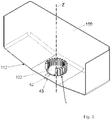
Fig. 3 shows a perspective view of part of a tank provided with the electric heater inFig. 1 ; -
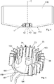
Fig. 4 shows a front view of the part of the tank inFig. 3 ; -
Fig. 5 shows a perspective view of the heater inFig. 1 and some parts of the tank. - The same references in the figures identify the same elements or components.
- With reference to the Figures, it is described an
electric heater 1, in particular to heat a substance inside atank 100, e.g. a tank for a water-injection system. - In general, the
electric heater 1 comprises abody 20 made of thermally conductive material, and at least oneheating element 40. - The
body 20 is provided with awall 23, preferably only one wall, which at least partially or only partially extends around an axis Z. The axis Z is preferably a straight axis, preferably a central axis, defined by thebody 20. - The
wall 23 comprises two mutuallyopposite faces wall 23, respectively. - The
body 20 is also provided with a plurality offins faces - In particular, a plurality of
fins 24 which extend from theface 21 and/or a plurality offins 25 which extend from theface 22 of thewall 23 can be provided. - The
face 22 and therespective fins 25, when provided, delimit an empty space. In particular, the entire space delimited by theface 22 is preferably empty. Theheater 1 can therefore be arranged around apump 101 of thetank 100, as will be further described. - Furthermore, the
body 20 is open at the top and bottom. - Preferably, the
body 20, in particular thewall 23 and thefins body 20 can advantageously be chosen according to the substance with which it will come into contact. In particular, the material of thebody 20 is chosen so that thebody 20 can be immersed in water or an aqueous solution containing urea, and that it is not an electrical conductor or has a very low electrical conductivity, such as aluminum. Optionally, thebody 20 is coated with polymer or ceramic material, or in any case with a material compatible with the liquid. For example, thebody 20 can be coated with polytetrafluoroethylene, e.g. Teflon@. By way of example, theentire body 20, comprising thefins 24 and/or 25, is coated with polymer or ceramic material. - Preferably, the
wall 23 is monolithic and preferably thebody 20 is monolithic. - In particular, preferably, the
wall 23 and thefins fins wall 23. In general, thebody 20 is preferably obtained by die-casting. In particular, thebody 20 is preferably obtained by die-casting by injection of material, in particular of the material of whichbody 20 is made, around thestretch 41 of the at least oneheating element 40 which is inside thewall 23. - Advantageously, the
body 20, especially thewall 23, is a self-supporting structure. Preferably, the height, in particular the maximum height, of thewall 23 parallel to the axis Z is between 50 and 90 mm, e.g. between 60 and 80 mm. Such a height is preferably constant or substantially constant. - Preferably, the maximum height of the
wall 23 corresponds to the maximum height of thebody 20. - Preferably, the height of the
fins wall 23. - Preferably, the
fins lower edge 26 and/or from theupper edge 27 of thewall 23. - Preferably, the
fins 24 are equally spaced between each other and/or thefins 25 are equally spaced between each other. - Preferably, a
fin 25 is provided at eachfin 24. In particular, eachfin 24 is optionally aligned with arespective fin 25, i.e. they are coplanar. Alternatively, thefins - Preferably, the width "L1", "L2" (
Fig. 1 ), or radial extension, of eachfin fin respective face fin - The width L1, L2 of each
fin - Preferably, the width of the
fins 24 and/or thefins 25 increases towards theupper edge 27 of thewall 23. - Preferably, the thickness "S1", "S2" (
Fig. 1 ) of eachfin - For each
fin - The thickness of each
fin - Preferably, the
fins respective face fins 24 extend radially outwards and thefins 25 extend radially inwards. - As mentioned above, the electric heater comprises at least one
heating element 40. The at least oneheating element 40 is adapted to be connected to a source of electricity (not shown) to generate heat, in particular by Joule effect. - The least one
heating element 40 comprises a stretch 41 (shown inFig. 2 ), preferably asingle stretch 41, which is arranged inside thewall 23, preferably completely inside thewall 23. In particular, such astretch 41 is located inside and in contact, more in particular in direct contact, with thewall 23. Thestretch 41 extends alongwall 23, around the axis Z. Thestretch 41 is substantially immersed in or surrounded by, in particular completely immersed in or surrounded by, thewall 23. - Therefore, the heat generated by the at least one
heating element 40 can be transmitted to thebody 20, which in turn transmits it to the substance to be heated. In other words, thebody 20 serves as a diffuser. - Preferably, the
heating element 40 crosses thewall 23, so that two stretches 42, 43 of the at least one heating element 4, between which saidstretch 41 extends, protrude from thewall 23. For example, thestretch 42 protrudes from thefirst end 235 of thewall 23 and/or thestretch 43 protrudes from thesecond end 236 of thewall 23. Preferably, thestretch 41 extends substantially on a single plane. In particular, the axis (preferably central) defined by thestretch 41, around which the outer wall or casing of thestretch 41 extends, extends substantially only on one plane. In other words, thestretch 41 is substantially flat. In particular, thestretch 41 does not form a winding. Theelectrical resistor 1 can therefore be easily made. Preferably, thestretch 41 is shaped as an open ring, i.e. it has an open annular shape. - Preferably, the
electric heater 1, and in particular thebody 20, is configured to avoid the passage to the gaseous phase of the substance to be heated. For example, theelectric heater 1 is preferably configured so that thebody 20 can reach a maximum temperature of about 90 °C, e.g. 90 °C. - Preferably, there is provided only one
heating element 40, although further heating elements can be provided. - Preferably, the
heating element 40 is an sheathed resistor. Preferably, such sheathed resistor comprises a casing containing at least one resistive element, such as a resistive wire. The casing, which is preferably tubular, is made of thermally conductive material, preferably metal, such as steel. The resistive element is preferably surrounded by or immersed in an electrically insulating material, e.g. magnesium oxide, contained in the casing. - Preferably, as mentioned, the
stretch 41 extends between twostretches wall 23. In particular, thestretches stretch 41. Such stretches 42, 43 are preferably folded, comprising at least one curved stretch, so as to be able to cross a wall of thetank 100, e.g. itsbottom wall 112, as will be described below. - The ends of
stretches - The source of electricity to which the
heating element 40 may be connected to generate heat is preferably the battery (not shown) of the motor-vehicle, which typically, but not exclusively, operates at a voltage of about 13 V. - Preferably, the
heating element 40 is proximal to an edge, e.g. thelower edge 26, of thewall 23 and distal to the opposite edge, e.g. theupper edge 27, of thewall 23. Preferably, thestretch 41 of theheating element 40 is arranged inside thelower edge 26 of thewall 23. - Preferably, the
wall 23 has a thickness, perpendicular to the axis Z, between 1 and 20 mm. Thewall thickness 23 can be constant or variable. Preferably, thewall thickness 23 corresponds to the distance, in particular the minimum distance, along a direction orthogonal to the axis Z, between theface 21 and theface 22 of thewall 23. - Furthermore, optionally, the
wall thickness 23 may have a portion with variable thickness and a portion with constant thickness. Preferably, the variable thickness portion has a height, parallel to the axis Z, greater than the height of the constant thickness portion. - Preferably, for a better heat distribution, all or part of the
portion 230 of thewall 23 comprised between thestretch 41 and theupper edge 27 has a decreasing thickness towards theupper edge 27. For example, the maximum thickness of theportion 230, can be between 10 and 20 mm; and the minimum thickness of theportion 230 can be between 1 and 10 mm. - In the example shown, only one
part 231 of theportion 230 has a decreasing thickness. - In this case, preferably, the part, or stretch, 232 of the
portion 230, adjacent to theportion 231 has a constant thickness, preferably equal to the minimum thickness of thepart 231. For example, the constant thickness of thepart 232 has a value between 1 and 10 mm. - The
portion 230 and its parts orsub-portions wall 23, which extend along the entire length of the wall 23 (the length is the dimension which at least partially extends around the axis Z). For illustrative purposes, inFig. 1 theportion 230 and itsparts part 231 is distal with respect to theupper edge 27, and thepart 232 is proximal to theupper edge 27 of thewall 23. More in detail, thepart 232 comprises theupper edge 27. - Preferably, the
lower edge 26 has a thickness, perpendicular to the axis Z, greater than the maximum thickness of theportion 230. Such a thickness of thelower edge 26 also comprises the dimension of thestretch 41 of theheating element 40. Preferably, the height, or extension, parallel to the axis Z of thewall 23 between the outer face, i.e. the lower face, of thelower edge 26 and thestretch 41 has a value between 1 and 40 mm. In a particular, non-limiting example, such a height is between 1 and 5 mm. In another particular example, thestretch 41 extends over a plane which is approximately half the height of theentire wall 23. - Preferably, the
entire wall 23 extends around the axis Z and theentire stretch 41 of theheating element 40 extends around the axis Z. - Preferably, but not exclusively, the
wall 23 is shaped as a ring, preferably as an open ring, as shown in the figures, or alternatively is shaped as a closed ring. When thewall 23 is shaped as an open ring, in particular, thewall 23 comprises twoseparate end surfaces faces - In the scope of the ring shape, the
wall 23 can optionally have one or more inlets facing outwards and/or inwards. - Preferably, the ring shape is such that the length, around the axis Z, of the
wall 23 defines a curved axis, preferably an arc of a circle. - Preferably, the
wall 23 has an inner diameter between 100 and 150 mm. Preferably, the minimum distance, along an axis perpendicular to the axis Z, between any two opposite points of theface 22 of thewall 23 is between 100 and 150 mm. - Preferably, the
stretch 41 of theheating element 40 defines a curvilinear axis which is substantially parallel to the curvilinear axis ofwall 23. - Preferably, the curvilinear axis of the
stretch 41 lies in a plane perpendicular to the axis Z. Preferably, the curvilinear axis ofstretch 41 lies completely on said plane perpendicular to the axis Z. - The invention also comprises a
tank 100, partially shown, to contain a substance, in particular a substance comprising water. Thetank 100 is provided with at least oneelectric heater 1, preferably only oneelectric heater 1, arranged inside it. - The 100 tank is preferably made of plastic, e.g. polyethylene.
- The
tank 100 is preferably the tank of a motor vehicle. In particular, thetank 100 is adapted to contain a liquid, e.g. water or an aqueous solution, e.g. such as a substance or an aqueous solution comprising urea. Thetank 100 is preferably adapted to be connected to a system (not shown) for saving fuel and reducing pollution of the motor vehicle, e.g. a system called water-injection. - Preferably, the
tank 100 comprises aninjection module 110. Theinjection module 110 comprises a support orflange 102, with which thepump 101 for the liquid is associated, in particular to which thepump 101 is fixed. Preferably, thepump 101 crosses theflange 102. Thepump 101 or pumping device is used to draw the liquid from thetank 100. Thepump 101 is diagrammatically shown inFig. 5 . - For example, the
flange 102 is a base support, preferably substantially flat. - The
flange 102 is preferably made of plastic, e.g. high-density polyethylene (HDPE). Theflange 102 is fixed to thetank 100, e.g. to thebottom wall 112 of thetank 100. In particular, such abottom wall 112 preferably has an opening which is closed by theflange 102. Theflange 102 and thebottom wall 112 are preferably fixed to each other by welding, e.g. ultrasonic welding, gluing or interlocking. - Preferably, the
flange 102 is fixed internally to thetank 100. - The
electric heater 1 is preferably fixed to theflange 102 which, as described above, is fixed in turn to thetank 100. - In particular, the
lower edge 26 of thebody 20, more in particular the lower surface (or outer face) of thelower edge 26, is preferably fixed to theflange 102 of theinjection module 110. The fixing is preferably a mechanical fixing, e.g. by interlocking, or by gluing. Preferably, thewall 23 rises vertically from theflange 102, i.e. it is preferable that the axis Z is substantially perpendicular to theflange 102. The assembly comprising theinjection module 110 and theheater 1 is shown inFig. 5 . - Preferably, the
bottom wall 102 of thetank 100 comprises two side portions between which a central portion extends, to which theinjection module 110 is fixed, and thus also theelectric heater 1. The side portions are inclined so as to form an obtuse angle of less than 180° inside thetank 100 with the central portion. - Preferably, the outer casing of the
pump 101 is made of plastic, e.g. polyethylene. - Preferably, the
pump 101 is arranged in a central zone of thebottom wall 112. - Advantageously, the
electric heater 1 is arranged around thepump 101. More in particular, thepump 101 is arranged in the space defined by theinner face 22 of thewall 23. Thereby, the frozen mass which is near thepump 101 can be thawed, so that the liquid can be effectively drawn from thetank 100. - More in particular, the axis of the
pump 101 is preferably near to or coincides with the axis Z defined by theelectric heater 1. - Optionally, a
liquid level sensor 103 and/or afurther sensor 104, e.g. a temperature sensor, are also located in the space delimited by theinner face 22 of thewall 23. Bothsensors Fig. 5 and are preferably part of theinjection module 110, e.g. being fixed to theflange 102. - Preferably, the height of the
wall 23 from theflange 102 is higher than the height of thepump 101 from theflange 102. - Preferably, the
fins flange 102. - Preferably, the
stretches bottom wall 112, so that their ends are outside thetank 100. - The zones of the
bottom wall 112 crossed by thestretches - According to an aspect, the disclosure also relates to a process, in particular a die-casting process, to obtain an
electric heater 1, wherein there is provided a step of injecting material around saidstretch 41 of at least oneheating element 40 to obtain thebody 20. - According to an aspect, the invention also relates to a system for saving fuel and reducing pollution of a motor vehicle comprising an
electric heater 1 or atank 100.
Claims (17)
- An electric heater (1) for heating, in particular thawing, an aqueous solution comprising urea inside a tank (100) to save fuel and reduce pollution of a motor vehicle, the electric heater (1) comprising- a thermally conductive body (20), provided witha wall (23) which at least partially extends around an axis (Z), comprising two opposite faces (21, 22);a plurality of fins (24, 25) which extend from at least one first face (21) of said two faces (21, 22);- at least one heating element (40),whereby in use of the electric heater (1) the heat generated by the at least one heating element (40) is transmitted to the body (20) which transmits the heat to a solution to be heated;
adapted to be connected to a source of electricity to generate heat, comprising a stretch (41) arranged inside the wall (23), which extends along the wall (23) around the axis (Z),wherein the stretch (41) of the heating element (40) defines a curvilinear axis which is substantially parallel to the curvilinear axis of wall (23);characterized in thatthe curvilinear axis defined by the stretch (41) lies completely in a plane perpendicular to the axis (Z). - An electric heater (1) according to claim 1, wherein said stretch (41) of the at least one heating element (40) is proximal to a lower edge (26) of the wall (23) and distal with respect to an upper edge (27) of the wall (23), or wherein said stretch (41) of the at least one heating element (40) is arranged at about half the height of the wall (23) along the axis (Z).
- An electric heater (1) according to claim 2, wherein said stretch (41) of the at least one heating element (40) is arranged in the lower edge (26) of the wall (23).
- An electric heater (1) according to any one of the preceding claims, wherein said wall (23) has an annular, preferably open annular, shape.
- An electric heater (1) according to any one of the preceding claims, wherein the thickness of said wall (23), perpendicular to said axis (Z), is between 1 and 20 mm; and/or wherein the height of said wall (23), parallel to said axis (Z), is between 50 and 90 mm.
- An electric heater (1) according to any one of the preceding claims, wherein a portion (230) of the wall (23) which extends between the stretch (41) and the upper edge (27) at least partially has a decreasing thickness towards the upper edge (27), and preferably has an end stretch (232) comprising the upper edge (27) and having a constant thickness.
- An electric heater (1) according to any one of the preceding claims, wherein there is provided only one heating element (40).
- An electric heater (1) according to any one of the preceding claims, wherein said heating element (40) is an sheathed resistor, and preferably wherein the stretch (41) extends between two stretches (42, 43) which protrude from the wall (23).
- An electric heater (1) according to any one of the preceding claims, wherein said fins (24, 25) extend both from the first face (21) and from a second face (22) of said two faces (21, 22).
- An electric heater (1) according to any one of the preceding claims, wherein the body (20) is made of metal, preferably aluminum or aluminum alloy.
- An electric heater (1) according to any one of the preceding claims, wherein the body (20) is coated with polymer or ceramic material, preferably polytetrafluoroethylene.
- An electric heater (1) according to any one of the preceding claims, configured so that the body (20) can reach a maximum temperature of about 90 °C.
- An electric heater (1) according to any one of the preceding claims, wherein the axis around which the outer part of said stretch (41) extends, substantially extends on a single plane and/or wherein said stretch has an open annular shape.
- A tank (100) for containing an aqueous solution comprising urea for saving fuel and reducing pollution of a motor vehicle, the tank (100) comprising therein at least one electric heater (1) according to any one of the preceding claims.
- A tank (100) according to claim 14, wherein said at least one electric heater (1) is fixed to an inner wall of the tank (100), preferably said inner wall (102) being a bottom wall of the tank (100).
- A tank (100) according to claim 14 or 15, comprising a pumping device (101) for the solution, wherein the electric heater (1) is arranged around said pumping device (101).
- A system for saving fuel and reducing pollution of a motor vehicle comprising an electric heater (1) according to any one of the claims from 1 to 13 or a tank (100) according to claim 14, 15 or 16.
Applications Claiming Priority (2)
| Application Number | Priority Date | Filing Date | Title |
|---|---|---|---|
| IT102018000007346A IT201800007346A1 (en) | 2018-07-19 | 2018-07-19 | ELECTRIC HEATER FOR TANK |
| PCT/IB2019/056197 WO2020016849A1 (en) | 2018-07-19 | 2019-07-19 | Electric heater for tank |
Publications (2)
| Publication Number | Publication Date |
|---|---|
| EP3824226A1 EP3824226A1 (en) | 2021-05-26 |
| EP3824226B1 true EP3824226B1 (en) | 2022-09-07 |
Family
ID=63834532
Family Applications (1)
| Application Number | Title | Priority Date | Filing Date |
|---|---|---|---|
| EP19762858.9A Active EP3824226B1 (en) | 2018-07-19 | 2019-07-19 | Electric heater for tank |
Country Status (4)
| Country | Link |
|---|---|
| US (1) | US20210262696A1 (en) |
| EP (1) | EP3824226B1 (en) |
| IT (1) | IT201800007346A1 (en) |
| WO (1) | WO2020016849A1 (en) |
Families Citing this family (2)
| Publication number | Priority date | Publication date | Assignee | Title |
|---|---|---|---|---|
| IT201900012903A1 (en) * | 2019-07-25 | 2021-01-25 | Irca Spa | ELECTRIC HEATER |
| IT201900022797A1 (en) * | 2019-12-03 | 2021-06-03 | Irca Spa | ELECTRIC HEATER TO HEAT A SUBSTANCE IN A MOTOR VEHICLE |
Family Cites Families (26)
| Publication number | Priority date | Publication date | Assignee | Title |
|---|---|---|---|---|
| US1766802A (en) * | 1929-04-18 | 1930-06-24 | Richard D Sanders | Fluid-heating apparatus |
| US5835679A (en) * | 1994-12-29 | 1998-11-10 | Energy Converters, Inc. | Polymeric immersion heating element with skeletal support and optional heat transfer fins |
| US6957013B2 (en) * | 2001-06-08 | 2005-10-18 | Algas-Sdi International Llc | Fluid heater |
| US6611660B1 (en) * | 2002-04-30 | 2003-08-26 | Cool Options, Inc. A New Hampshire Corp. | Radial fin thermal transfer element and method of manufacturing same |
| FR2916188B1 (en) * | 2007-05-16 | 2011-05-06 | Inergy Automotive Systems Res | A UREA AND EMBASE TANK WITH INTEGRATED HEATING ELEMENT. |
| US20110062137A1 (en) * | 2007-07-18 | 2011-03-17 | Chia-Hsiung Wu | Vehicular fluid heater |
| DE102007034370A1 (en) * | 2007-07-24 | 2009-01-29 | Bleckmann Gmbh & Co. Kg | Compact high-pressure spiral flow heating unit |
| US20110056927A1 (en) * | 2007-07-30 | 2011-03-10 | Chia-Hsiung Wu | Binding process for an air heater and structure thereof |
| CN201141687Y (en) * | 2007-09-04 | 2008-10-29 | 厦门灿坤实业股份有限公司 | a heater |
| DE102009041938B4 (en) * | 2009-09-17 | 2013-10-31 | Seuffer Gmbh & Co.Kg | Heating arrangement |
| JP2012124222A (en) * | 2010-12-06 | 2012-06-28 | Mitsubishi Heavy Ind Ltd | Heat medium heating apparatus |
| DE102011014626A1 (en) * | 2011-03-21 | 2012-09-27 | Eichenauer Heizelemente Gmbh & Co. Kg | Electric heater |
| CN103517469B (en) * | 2012-06-27 | 2015-03-04 | 比亚迪股份有限公司 | PTC electrical heating element, electric heater unit and electric car |
| DE102013001237B4 (en) * | 2013-01-25 | 2015-04-16 | Kautex Textron Gmbh & Co. Kg | Filter device for a liquid container, in particular for aqueous urea solution |
| DE102014105288B4 (en) * | 2014-04-14 | 2021-04-01 | Eichenauer Heizelemente Gmbh & Co. Kg | Filter heater for reducing agents and method for producing a heater |
| CN107072435B (en) * | 2014-07-31 | 2019-11-08 | I.R.C.A.(共同)股份公司工业铠装及类似电阻 | Heat Exchanger |
| CN106659353B (en) * | 2014-08-22 | 2019-03-15 | Lg 电子株式会社 | Pump and dishwasher including the same |
| EP3013116A1 (en) * | 2014-10-21 | 2016-04-27 | Bleckmann GmbH & Co. KG | Heating system component and method for producing same |
| US11207438B2 (en) * | 2015-05-27 | 2021-12-28 | S. C. Johnson & Son, Inc. | Low wattage powered wax warmers |
| EP3319399A4 (en) * | 2015-06-30 | 2018-07-25 | Calsonic Kansei Corporation | Fluid heating device |
| JP6471109B2 (en) * | 2015-06-30 | 2019-02-13 | カルソニックカンセイ株式会社 | Fluid heating device |
| US20170131019A1 (en) * | 2015-11-05 | 2017-05-11 | General Electric Company | Refrigerator Appliance |
| ITUB20155359A1 (en) * | 2015-11-06 | 2017-05-06 | Eltek Spa | TANK COMPONENT, IN PARTICULAR FOR GAS EXHAUST SYSTEMS FOR INTERNAL COMBUSTION ENGINES |
| IT201600078782A1 (en) * | 2016-07-27 | 2018-01-27 | Irca Spa | COVER FOR CENTRIFUGAL PUMP |
| FR3062710B1 (en) * | 2017-02-06 | 2019-03-22 | Akwel | CORROSIVE FLUID HEATER FOR METALS, RESERVOIR, AND MANUFACTURING METHOD THEREFOR. |
| IT201700048641A1 (en) * | 2017-05-05 | 2018-11-05 | Eltek Spa | ELECTRIC HEATER DEVICE, PARTICULARLY WITH PTC EFFECT |
-
2018
- 2018-07-19 IT IT102018000007346A patent/IT201800007346A1/en unknown
-
2019
- 2019-07-19 WO PCT/IB2019/056197 patent/WO2020016849A1/en not_active Ceased
- 2019-07-19 US US17/260,679 patent/US20210262696A1/en not_active Abandoned
- 2019-07-19 EP EP19762858.9A patent/EP3824226B1/en active Active
Also Published As
| Publication number | Publication date |
|---|---|
| WO2020016849A1 (en) | 2020-01-23 |
| IT201800007346A1 (en) | 2020-01-19 |
| US20210262696A1 (en) | 2021-08-26 |
| EP3824226A1 (en) | 2021-05-26 |
Similar Documents
| Publication | Publication Date | Title |
|---|---|---|
| CN104144806B (en) | Cooling water heating type heating | |
| CN103261607B (en) | Tank loading type module, liquid tank | |
| CN108882417B (en) | Electric heater | |
| EP2948233B1 (en) | Filter apparatus for a liquid vessel, in particular for aqueous urea solution | |
| US20210262696A1 (en) | Electric heater for tank | |
| WO2018050895A1 (en) | Demineralized water tank on board of a vehicle | |
| US4883943A (en) | Electric heater for fuel tank discharge opening coupling to prevent fuel waxing | |
| KR20140004470A (en) | Cooling-water heating type heater | |
| US11378000B2 (en) | Coolant heater for a vehicle | |
| KR101894465B1 (en) | Cooling-water heating type heater | |
| EP4070625B1 (en) | Electric heater for heating a substance in a motor vehicle | |
| KR101895480B1 (en) | Cooling-water heating type heater | |
| RU2242096C2 (en) | Tubular electric heater | |
| KR20150098862A (en) | Cooling-water heating type heater | |
| EP3824694B1 (en) | Electric heater for tank | |
| EP3639622B1 (en) | Flexible resistor | |
| EP4070624B1 (en) | Electric heater for heating a substance in a motor vehicle | |
| KR102820166B1 (en) | Battery heating device of electric motor vehicle | |
| KR101973522B1 (en) | Coolant heater | |
| KR102768005B1 (en) | Battery heating device of electric motor vehicle | |
| KR20180112575A (en) | Electric heating type cooling water heater | |
| KR20220079343A (en) | Electric heating type urea sender and urea tank having the same | |
| BR202016005451U2 (en) | EXTENDED AREA HEATER AND HIGH PERFORMANCE FOR FUEL HEATING |
Legal Events
| Date | Code | Title | Description |
|---|---|---|---|
| STAA | Information on the status of an ep patent application or granted ep patent |
Free format text: STATUS: UNKNOWN |
|
| STAA | Information on the status of an ep patent application or granted ep patent |
Free format text: STATUS: THE INTERNATIONAL PUBLICATION HAS BEEN MADE |
|
| PUAI | Public reference made under article 153(3) epc to a published international application that has entered the european phase |
Free format text: ORIGINAL CODE: 0009012 |
|
| STAA | Information on the status of an ep patent application or granted ep patent |
Free format text: STATUS: REQUEST FOR EXAMINATION WAS MADE |
|
| 17P | Request for examination filed |
Effective date: 20210217 |
|
| AK | Designated contracting states |
Kind code of ref document: A1 Designated state(s): AL AT BE BG CH CY CZ DE DK EE ES FI FR GB GR HR HU IE IS IT LI LT LU LV MC MK MT NL NO PL PT RO RS SE SI SK SM TR |
|
| DAV | Request for validation of the european patent (deleted) | ||
| DAX | Request for extension of the european patent (deleted) | ||
| GRAP | Despatch of communication of intention to grant a patent |
Free format text: ORIGINAL CODE: EPIDOSNIGR1 |
|
| STAA | Information on the status of an ep patent application or granted ep patent |
Free format text: STATUS: GRANT OF PATENT IS INTENDED |
|
| RIC1 | Information provided on ipc code assigned before grant |
Ipc: H05B 3/78 20060101ALI20220202BHEP Ipc: H05B 3/82 20060101ALI20220202BHEP Ipc: F24H 1/12 20060101ALI20220202BHEP Ipc: F01N 3/20 20060101ALI20220202BHEP Ipc: F01N 3/00 20060101ALI20220202BHEP Ipc: F24H 1/10 20060101AFI20220202BHEP |
|
| INTG | Intention to grant announced |
Effective date: 20220221 |
|
| GRAS | Grant fee paid |
Free format text: ORIGINAL CODE: EPIDOSNIGR3 |
|
| GRAA | (expected) grant |
Free format text: ORIGINAL CODE: 0009210 |
|
| STAA | Information on the status of an ep patent application or granted ep patent |
Free format text: STATUS: THE PATENT HAS BEEN GRANTED |
|
| AK | Designated contracting states |
Kind code of ref document: B1 Designated state(s): AL AT BE BG CH CY CZ DE DK EE ES FI FR GB GR HR HU IE IS IT LI LT LU LV MC MK MT NL NO PL PT RO RS SE SI SK SM TR |
|
| REG | Reference to a national code |
Ref country code: GB Ref legal event code: FG4D |
|
| REG | Reference to a national code |
Ref country code: CH Ref legal event code: EP Ref country code: AT Ref legal event code: REF Ref document number: 1517357 Country of ref document: AT Kind code of ref document: T Effective date: 20220915 |
|
| REG | Reference to a national code |
Ref country code: IE Ref legal event code: FG4D |
|
| REG | Reference to a national code |
Ref country code: DE Ref legal event code: R096 Ref document number: 602019019360 Country of ref document: DE |
|
| REG | Reference to a national code |
Ref country code: LT Ref legal event code: MG9D |
|
| REG | Reference to a national code |
Ref country code: NL Ref legal event code: MP Effective date: 20220907 |
|
| PG25 | Lapsed in a contracting state [announced via postgrant information from national office to epo] |
Ref country code: SE Free format text: LAPSE BECAUSE OF FAILURE TO SUBMIT A TRANSLATION OF THE DESCRIPTION OR TO PAY THE FEE WITHIN THE PRESCRIBED TIME-LIMIT Effective date: 20220907 Ref country code: RS Free format text: LAPSE BECAUSE OF FAILURE TO SUBMIT A TRANSLATION OF THE DESCRIPTION OR TO PAY THE FEE WITHIN THE PRESCRIBED TIME-LIMIT Effective date: 20220907 Ref country code: NO Free format text: LAPSE BECAUSE OF FAILURE TO SUBMIT A TRANSLATION OF THE DESCRIPTION OR TO PAY THE FEE WITHIN THE PRESCRIBED TIME-LIMIT Effective date: 20221207 Ref country code: LV Free format text: LAPSE BECAUSE OF FAILURE TO SUBMIT A TRANSLATION OF THE DESCRIPTION OR TO PAY THE FEE WITHIN THE PRESCRIBED TIME-LIMIT Effective date: 20220907 Ref country code: LT Free format text: LAPSE BECAUSE OF FAILURE TO SUBMIT A TRANSLATION OF THE DESCRIPTION OR TO PAY THE FEE WITHIN THE PRESCRIBED TIME-LIMIT Effective date: 20220907 Ref country code: FI Free format text: LAPSE BECAUSE OF FAILURE TO SUBMIT A TRANSLATION OF THE DESCRIPTION OR TO PAY THE FEE WITHIN THE PRESCRIBED TIME-LIMIT Effective date: 20220907 |
|
| REG | Reference to a national code |
Ref country code: AT Ref legal event code: MK05 Ref document number: 1517357 Country of ref document: AT Kind code of ref document: T Effective date: 20220907 |
|
| PG25 | Lapsed in a contracting state [announced via postgrant information from national office to epo] |
Ref country code: HR Free format text: LAPSE BECAUSE OF FAILURE TO SUBMIT A TRANSLATION OF THE DESCRIPTION OR TO PAY THE FEE WITHIN THE PRESCRIBED TIME-LIMIT Effective date: 20220907 Ref country code: GR Free format text: LAPSE BECAUSE OF FAILURE TO SUBMIT A TRANSLATION OF THE DESCRIPTION OR TO PAY THE FEE WITHIN THE PRESCRIBED TIME-LIMIT Effective date: 20221208 |
|
| PG25 | Lapsed in a contracting state [announced via postgrant information from national office to epo] |
Ref country code: SM Free format text: LAPSE BECAUSE OF FAILURE TO SUBMIT A TRANSLATION OF THE DESCRIPTION OR TO PAY THE FEE WITHIN THE PRESCRIBED TIME-LIMIT Effective date: 20220907 Ref country code: RO Free format text: LAPSE BECAUSE OF FAILURE TO SUBMIT A TRANSLATION OF THE DESCRIPTION OR TO PAY THE FEE WITHIN THE PRESCRIBED TIME-LIMIT Effective date: 20220907 Ref country code: PT Free format text: LAPSE BECAUSE OF FAILURE TO SUBMIT A TRANSLATION OF THE DESCRIPTION OR TO PAY THE FEE WITHIN THE PRESCRIBED TIME-LIMIT Effective date: 20230109 Ref country code: ES Free format text: LAPSE BECAUSE OF FAILURE TO SUBMIT A TRANSLATION OF THE DESCRIPTION OR TO PAY THE FEE WITHIN THE PRESCRIBED TIME-LIMIT Effective date: 20220907 Ref country code: CZ Free format text: LAPSE BECAUSE OF FAILURE TO SUBMIT A TRANSLATION OF THE DESCRIPTION OR TO PAY THE FEE WITHIN THE PRESCRIBED TIME-LIMIT Effective date: 20220907 Ref country code: AT Free format text: LAPSE BECAUSE OF FAILURE TO SUBMIT A TRANSLATION OF THE DESCRIPTION OR TO PAY THE FEE WITHIN THE PRESCRIBED TIME-LIMIT Effective date: 20220907 |
|
| PG25 | Lapsed in a contracting state [announced via postgrant information from national office to epo] |
Ref country code: SK Free format text: LAPSE BECAUSE OF FAILURE TO SUBMIT A TRANSLATION OF THE DESCRIPTION OR TO PAY THE FEE WITHIN THE PRESCRIBED TIME-LIMIT Effective date: 20220907 Ref country code: PL Free format text: LAPSE BECAUSE OF FAILURE TO SUBMIT A TRANSLATION OF THE DESCRIPTION OR TO PAY THE FEE WITHIN THE PRESCRIBED TIME-LIMIT Effective date: 20220907 Ref country code: IS Free format text: LAPSE BECAUSE OF FAILURE TO SUBMIT A TRANSLATION OF THE DESCRIPTION OR TO PAY THE FEE WITHIN THE PRESCRIBED TIME-LIMIT Effective date: 20230107 Ref country code: EE Free format text: LAPSE BECAUSE OF FAILURE TO SUBMIT A TRANSLATION OF THE DESCRIPTION OR TO PAY THE FEE WITHIN THE PRESCRIBED TIME-LIMIT Effective date: 20220907 |
|
| REG | Reference to a national code |
Ref country code: DE Ref legal event code: R097 Ref document number: 602019019360 Country of ref document: DE |
|
| PG25 | Lapsed in a contracting state [announced via postgrant information from national office to epo] |
Ref country code: NL Free format text: LAPSE BECAUSE OF FAILURE TO SUBMIT A TRANSLATION OF THE DESCRIPTION OR TO PAY THE FEE WITHIN THE PRESCRIBED TIME-LIMIT Effective date: 20220907 Ref country code: AL Free format text: LAPSE BECAUSE OF FAILURE TO SUBMIT A TRANSLATION OF THE DESCRIPTION OR TO PAY THE FEE WITHIN THE PRESCRIBED TIME-LIMIT Effective date: 20220907 |
|
| P01 | Opt-out of the competence of the unified patent court (upc) registered |
Effective date: 20230525 |
|
| PLBE | No opposition filed within time limit |
Free format text: ORIGINAL CODE: 0009261 |
|
| STAA | Information on the status of an ep patent application or granted ep patent |
Free format text: STATUS: NO OPPOSITION FILED WITHIN TIME LIMIT |
|
| PG25 | Lapsed in a contracting state [announced via postgrant information from national office to epo] |
Ref country code: DK Free format text: LAPSE BECAUSE OF FAILURE TO SUBMIT A TRANSLATION OF THE DESCRIPTION OR TO PAY THE FEE WITHIN THE PRESCRIBED TIME-LIMIT Effective date: 20220907 |
|
| 26N | No opposition filed |
Effective date: 20230608 |
|
| PG25 | Lapsed in a contracting state [announced via postgrant information from national office to epo] |
Ref country code: SI Free format text: LAPSE BECAUSE OF FAILURE TO SUBMIT A TRANSLATION OF THE DESCRIPTION OR TO PAY THE FEE WITHIN THE PRESCRIBED TIME-LIMIT Effective date: 20220907 |
|
| PG25 | Lapsed in a contracting state [announced via postgrant information from national office to epo] |
Ref country code: MC Free format text: LAPSE BECAUSE OF FAILURE TO SUBMIT A TRANSLATION OF THE DESCRIPTION OR TO PAY THE FEE WITHIN THE PRESCRIBED TIME-LIMIT Effective date: 20220907 |
|
| PG25 | Lapsed in a contracting state [announced via postgrant information from national office to epo] |
Ref country code: MC Free format text: LAPSE BECAUSE OF FAILURE TO SUBMIT A TRANSLATION OF THE DESCRIPTION OR TO PAY THE FEE WITHIN THE PRESCRIBED TIME-LIMIT Effective date: 20220907 |
|
| REG | Reference to a national code |
Ref country code: CH Ref legal event code: PL |
|
| REG | Reference to a national code |
Ref country code: BE Ref legal event code: MM Effective date: 20230731 |
|
| PG25 | Lapsed in a contracting state [announced via postgrant information from national office to epo] |
Ref country code: LU Free format text: LAPSE BECAUSE OF NON-PAYMENT OF DUE FEES Effective date: 20230719 |
|
| PG25 | Lapsed in a contracting state [announced via postgrant information from national office to epo] |
Ref country code: LU Free format text: LAPSE BECAUSE OF NON-PAYMENT OF DUE FEES Effective date: 20230719 |
|
| REG | Reference to a national code |
Ref country code: IE Ref legal event code: MM4A |
|
| PG25 | Lapsed in a contracting state [announced via postgrant information from national office to epo] |
Ref country code: CH Free format text: LAPSE BECAUSE OF NON-PAYMENT OF DUE FEES Effective date: 20230731 |
|
| PG25 | Lapsed in a contracting state [announced via postgrant information from national office to epo] |
Ref country code: BE Free format text: LAPSE BECAUSE OF NON-PAYMENT OF DUE FEES Effective date: 20230731 |
|
| PG25 | Lapsed in a contracting state [announced via postgrant information from national office to epo] |
Ref country code: IE Free format text: LAPSE BECAUSE OF NON-PAYMENT OF DUE FEES Effective date: 20230719 |
|
| PG25 | Lapsed in a contracting state [announced via postgrant information from national office to epo] |
Ref country code: IE Free format text: LAPSE BECAUSE OF NON-PAYMENT OF DUE FEES Effective date: 20230719 |
|
| PG25 | Lapsed in a contracting state [announced via postgrant information from national office to epo] |
Ref country code: BG Free format text: LAPSE BECAUSE OF FAILURE TO SUBMIT A TRANSLATION OF THE DESCRIPTION OR TO PAY THE FEE WITHIN THE PRESCRIBED TIME-LIMIT Effective date: 20220907 |
|
| PG25 | Lapsed in a contracting state [announced via postgrant information from national office to epo] |
Ref country code: BG Free format text: LAPSE BECAUSE OF FAILURE TO SUBMIT A TRANSLATION OF THE DESCRIPTION OR TO PAY THE FEE WITHIN THE PRESCRIBED TIME-LIMIT Effective date: 20220907 |
|
| PG25 | Lapsed in a contracting state [announced via postgrant information from national office to epo] |
Ref country code: CY Free format text: LAPSE BECAUSE OF FAILURE TO SUBMIT A TRANSLATION OF THE DESCRIPTION OR TO PAY THE FEE WITHIN THE PRESCRIBED TIME-LIMIT; INVALID AB INITIO Effective date: 20190719 |
|
| PG25 | Lapsed in a contracting state [announced via postgrant information from national office to epo] |
Ref country code: HU Free format text: LAPSE BECAUSE OF FAILURE TO SUBMIT A TRANSLATION OF THE DESCRIPTION OR TO PAY THE FEE WITHIN THE PRESCRIBED TIME-LIMIT; INVALID AB INITIO Effective date: 20190719 |
|
| PGFP | Annual fee paid to national office [announced via postgrant information from national office to epo] |
Ref country code: DE Payment date: 20250722 Year of fee payment: 7 |
|
| PGFP | Annual fee paid to national office [announced via postgrant information from national office to epo] |
Ref country code: IT Payment date: 20250730 Year of fee payment: 7 |
|
| PGFP | Annual fee paid to national office [announced via postgrant information from national office to epo] |
Ref country code: GB Payment date: 20250722 Year of fee payment: 7 |
|
| PGFP | Annual fee paid to national office [announced via postgrant information from national office to epo] |
Ref country code: FR Payment date: 20250725 Year of fee payment: 7 |
|
| PG25 | Lapsed in a contracting state [announced via postgrant information from national office to epo] |
Ref country code: TR Free format text: LAPSE BECAUSE OF FAILURE TO SUBMIT A TRANSLATION OF THE DESCRIPTION OR TO PAY THE FEE WITHIN THE PRESCRIBED TIME-LIMIT Effective date: 20220907 |