EP3823536B1 - Ultrasound patch for detecting fluid flow - Google Patents
Ultrasound patch for detecting fluid flow Download PDFInfo
- Publication number
- EP3823536B1 EP3823536B1 EP19838308.5A EP19838308A EP3823536B1 EP 3823536 B1 EP3823536 B1 EP 3823536B1 EP 19838308 A EP19838308 A EP 19838308A EP 3823536 B1 EP3823536 B1 EP 3823536B1
- Authority
- EP
- European Patent Office
- Prior art keywords
- patient
- transducer
- elements
- ultrasound
- transmit
- Prior art date
- Legal status (The legal status is an assumption and is not a legal conclusion. Google has not performed a legal analysis and makes no representation as to the accuracy of the status listed.)
- Active
Links
Images













Classifications
-
- A—HUMAN NECESSITIES
- A61—MEDICAL OR VETERINARY SCIENCE; HYGIENE
- A61B—DIAGNOSIS; SURGERY; IDENTIFICATION
- A61B8/00—Diagnosis using ultrasonic, sonic or infrasonic waves
- A61B8/44—Constructional features of the ultrasonic, sonic or infrasonic diagnostic device
- A61B8/4483—Constructional features of the ultrasonic, sonic or infrasonic diagnostic device characterised by features of the ultrasound transducer
- A61B8/4488—Constructional features of the ultrasonic, sonic or infrasonic diagnostic device characterised by features of the ultrasound transducer the transducer being a phased array
-
- A—HUMAN NECESSITIES
- A61—MEDICAL OR VETERINARY SCIENCE; HYGIENE
- A61B—DIAGNOSIS; SURGERY; IDENTIFICATION
- A61B8/00—Diagnosis using ultrasonic, sonic or infrasonic waves
- A61B8/06—Measuring blood flow
-
- A—HUMAN NECESSITIES
- A61—MEDICAL OR VETERINARY SCIENCE; HYGIENE
- A61B—DIAGNOSIS; SURGERY; IDENTIFICATION
- A61B8/00—Diagnosis using ultrasonic, sonic or infrasonic waves
- A61B8/08—Clinical applications
- A61B8/0883—Clinical applications for diagnosis of the heart
-
- A—HUMAN NECESSITIES
- A61—MEDICAL OR VETERINARY SCIENCE; HYGIENE
- A61B—DIAGNOSIS; SURGERY; IDENTIFICATION
- A61B8/00—Diagnosis using ultrasonic, sonic or infrasonic waves
- A61B8/42—Details of probe positioning or probe attachment to the patient
- A61B8/4209—Details of probe positioning or probe attachment to the patient by using holders, e.g. positioning frames
- A61B8/4236—Details of probe positioning or probe attachment to the patient by using holders, e.g. positioning frames characterised by adhesive patches
-
- A—HUMAN NECESSITIES
- A61—MEDICAL OR VETERINARY SCIENCE; HYGIENE
- A61B—DIAGNOSIS; SURGERY; IDENTIFICATION
- A61B8/00—Diagnosis using ultrasonic, sonic or infrasonic waves
- A61B8/42—Details of probe positioning or probe attachment to the patient
- A61B8/4272—Details of probe positioning or probe attachment to the patient involving the acoustic interface between the transducer and the tissue
- A61B8/4281—Details of probe positioning or probe attachment to the patient involving the acoustic interface between the transducer and the tissue characterised by sound-transmitting media or devices for coupling the transducer to the tissue
-
- A—HUMAN NECESSITIES
- A61—MEDICAL OR VETERINARY SCIENCE; HYGIENE
- A61B—DIAGNOSIS; SURGERY; IDENTIFICATION
- A61B8/00—Diagnosis using ultrasonic, sonic or infrasonic waves
- A61B8/48—Diagnostic techniques
- A61B8/488—Diagnostic techniques involving Doppler signals
-
- A—HUMAN NECESSITIES
- A61—MEDICAL OR VETERINARY SCIENCE; HYGIENE
- A61B—DIAGNOSIS; SURGERY; IDENTIFICATION
- A61B8/00—Diagnosis using ultrasonic, sonic or infrasonic waves
- A61B8/56—Details of data transmission or power supply
-
- B—PERFORMING OPERATIONS; TRANSPORTING
- B06—GENERATING OR TRANSMITTING MECHANICAL VIBRATIONS IN GENERAL
- B06B—METHODS OR APPARATUS FOR GENERATING OR TRANSMITTING MECHANICAL VIBRATIONS OF INFRASONIC, SONIC, OR ULTRASONIC FREQUENCY, e.g. FOR PERFORMING MECHANICAL WORK IN GENERAL
- B06B1/00—Methods or apparatus for generating mechanical vibrations of infrasonic, sonic, or ultrasonic frequency
- B06B1/02—Methods or apparatus for generating mechanical vibrations of infrasonic, sonic, or ultrasonic frequency making use of electrical energy
- B06B1/06—Methods or apparatus for generating mechanical vibrations of infrasonic, sonic, or ultrasonic frequency making use of electrical energy operating with piezoelectric effect or with electrostriction
- B06B1/0607—Methods or apparatus for generating mechanical vibrations of infrasonic, sonic, or ultrasonic frequency making use of electrical energy operating with piezoelectric effect or with electrostriction using multiple elements
-
- B—PERFORMING OPERATIONS; TRANSPORTING
- B06—GENERATING OR TRANSMITTING MECHANICAL VIBRATIONS IN GENERAL
- B06B—METHODS OR APPARATUS FOR GENERATING OR TRANSMITTING MECHANICAL VIBRATIONS OF INFRASONIC, SONIC, OR ULTRASONIC FREQUENCY, e.g. FOR PERFORMING MECHANICAL WORK IN GENERAL
- B06B1/00—Methods or apparatus for generating mechanical vibrations of infrasonic, sonic, or ultrasonic frequency
- B06B1/02—Methods or apparatus for generating mechanical vibrations of infrasonic, sonic, or ultrasonic frequency making use of electrical energy
- B06B1/06—Methods or apparatus for generating mechanical vibrations of infrasonic, sonic, or ultrasonic frequency making use of electrical energy operating with piezoelectric effect or with electrostriction
- B06B1/0607—Methods or apparatus for generating mechanical vibrations of infrasonic, sonic, or ultrasonic frequency making use of electrical energy operating with piezoelectric effect or with electrostriction using multiple elements
- B06B1/0622—Methods or apparatus for generating mechanical vibrations of infrasonic, sonic, or ultrasonic frequency making use of electrical energy operating with piezoelectric effect or with electrostriction using multiple elements on one surface
Definitions
- the disclosed technology relates to ultrasound devices designed to detect fluid flow in a vessel.
- WO 2018/102911 A1 discloses a device for automatically assessing functional hemodynamic properties of a patient is provided, the device comprising: a housing; an ultrasound unit coupled to the housing and adapted for adducing ultrasonic waves into the patient at a vessel; a detector adapted to sense signals obtained as a result of adducing ultrasonic waves into the patient at the vessel and to record the; and a processor adapted for receiving the recorded signals as data and transforming the data for output at an interface.
- Other devices, systems, methods, and/or computer-readable media may be provided in relation to assessing functional hemodynamics of a patient.
- US 2017/105700 A1 discloses a system for continuous ultrasonic monitoring including an ultrasound transducer.
- the ultrasound transducer includes an array of ultrasonic transducer elements.
- the ultrasonic transducer elements are operable to steer and focus an ultrasound beam to a selectable location and to receive an ultrasound signal from the selectable location.
- a holder is provided for holding the ultrasound transducer, the holder being attachable to a skin surface of a patient.
- a controller is configured to repeatedly steer and focus the ultrasound beam to identify a target section of an object inside the body of the patient and to acquire an ultrasound image such that the target section is maintained within the acquired ultrasound image.
- the invention provides an ultrasound patch according to claim 1.
- Optional features are set out in the dependent claims.
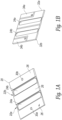
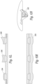
- Figures 1A and 1B are isometric front and back views of a printed circuit board 20 that is configured to support a pair of piezoelectric transducer elements.
- the circuit board 20 is rectangular and includes a pair of spaced, parallel milled slots 22a, 22b, running from one edge to another edge. Each slot includes an opening or hole 24a, 24b that is nearly the size of the slot and extends through the printed circuit board.
- the holes 24a, 24b provide an opening to the rear surface of the transducer elements (not shown) when they are mounted in the slots on the printed circuit board.
- the circuit board 20 is about 3 cm. on each side although the printed circuit board could be made larger or smaller.
- a top surface of the printed circuit board 20 includes a common ground electrode 26 made of a conductive material such as gold, copper or aluminum.
- the common ground electrode covers the entire top surface of the printed circuit board except for the area of the milled slots 22.
- a pair of through holes or vias 30a, 30b extend from the top surface of the board to the rear surface of the board for an electrical connection to the ground electrode on the front of the printed circuit board.
- FIG 1B shows a rear surface of the printed circuit board 20 shown in Figure 1A .
- the rear surface includes a pair of signal electrodes 32a, 32b surrounding each of the back sides of the slots and the openings 24a, 24b.
- the signal electrodes 32a, 32b are not electrically connected to each other so that the transducer elements on the front surface of the printed circuit board can be driven separately.
- the rear surface of the printed circuit board also includes a pair of ground electrodes 34a, 34b. In one embodiment, these ground electrodes 34a, 34b on the back side of the printed circuit board are electrically coupled to the ground electrodes 26 on the front surface of the printed circuit board through the vias 30a, 30b or another conductive path.
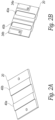
- FIGs 2A and 2B show the printed circuit board of Figures 1A, 1B with a pair of transducer elements 40a, 40b secured thereto.
- each of the transducers elements 40a, 40b comprises a rectangular sheet of PZT or other piezoelectric material.
- the transducer elements 40a, 40b are secured in the slots of the printed circuit board with a non-conductive epoxy.
- the top and bottom surfaces of the transducer elements include a conductive electrode such as a metallic coating (gold, copper or the like).
- Figure 2B shows the printed circuit board 20 with the transducer elements 40a, 40b secured in the slots and the openings 24a, 24b aligned with rear surface of the transducer elements.
- the electrodes on the PZT sheets are electrically connected to the conductive traces on the printed circuit board 20 with a conductive epoxy such as EPO-TEK H20E that bridges the gap between the surface of the printed circuit board and the electrodes on the PZT sheets.
- a metal foil or other conductor could be used to electrically connect the traces on the printed circuit board to the electrodes on the transducer elements.
- micro-coaxial conductors (not shown) are connected to the signal electrodes.
- the signal electrodes for each transducer element are electrically separate while the ground electrodes on the printed circuit board and the transducer elements are commonly connected.
- the ground electrodes on the transducer elements are facing forward and the signal electrodes are on the rear surface. It will be appreciated that this could be reversed with the ground electrode on the rear surface and the signal electrodes on the front surface.
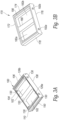
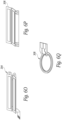
- Figures 3A and 3B show two embodiments of a frame that supports the printed circuit board and the transducer elements.
- a frame 100 includes bottom floor 102 and a set of sidewalls 104, 106, 108, 110 that extend outwardly from the bottom floor and surround the perimeter of the bottom floor 102.
- a center beam 120 connects the sidewall 104 to the sidewall 108 and divides the open space between the sidewalls of the frame into a first cavity 126a and a second cavity 126b.
- the cavities 126a, 126b are air filled and are aligned behind the exposed rear surfaces of the transducer elements.
- the sidewalls 104 and 108 also include pairs of aligned holes 130 through which a micro-coaxial cable or other conductor can be passed.
- the top perimeter of the sidewalls 104, 106, 108, 110 includes a lip around the interior of the edge that is sized to receive the perimeter of the printed circuit board 20 shown in Figures 1A, 1B , 2A, 2B .
- the printed circuit board 20 is held in the frame 100 with an adhesive.
- the sidewalls 106, 110 include a horizontally extending groove 150 on the exterior of opposing sidewalls 106, 110 that is configured to receive a flexible member such a metal, plastic or graphite rod in order to keep multiple frames aligned as will be explained in further detail below.
- a frame 170 is formed without the bottom floor.
- the frame 170 includes four connected sidewalls 172, 174, 176, 178 where the sidewalls 172 and 176 are joined by a center beam 180 that divides the open space between the sidewalls into a pair of cavities 182a, 182b.
- a lip 190 around the interior of the top surface of the sidewalls is sized to receive the outer perimeter of the printed circuit board so that the printed circuit board can be secured to the frame 170 with an adhesive or the like.
- the sidewall 176 also includes pair of holes 192a, 192b through which electrical connectors such as micro-coaxial cables can pass.
- the holes 192a, 192b are only on the sidewall 176 and therefore the frame is not designed to be electrically connected to other frames. In this embodiment, because the frame 170 lacks a bottom floor, the cavities 182a, 182b are open to the air.
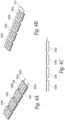
- Figure 4A shows a number of frames 100a, 100b, 100c, 100d that are positioned side by side in a line.
- a pair of flexible alignment members 198 such as flexible metal, plastic or graphite rods are positioned in the sidewall grooves of each frame to align the frames and to permit the frames to bend and conform to a curved shape of a subject's anatomy.
- a set of conductors such as micro-coaxial cables 202a, 202b electrically connect the transducer elements in each frame in parallel.
- one transducer element in each frame is a transmit (TX) element and the other transducer element is a receive (RX) element.
- all the TX transducer elements of the aligned frames are connected in parallel while all the RX transducer elements are connected in parallel.
- each of the TX and RX elements can be controlled separately. This has the benefit of being to select a TX/RX pair that is best positioned over a desired vessel to produce the signals required to analyze flow.
- Figure 4C shows a side view of a series of aligned transducer frames 100a, 100b, 100c, 100d. Because the micro co-axial cables or the flex circuit joining the frames are flexible, the arrangement of connected transducer frames can bend and conform to a subject's anatomy such as the subject's neck if the device is to measure blood flow in the carotid artery.
- the transducer elements are flat and are aligned to transmit and receive ultrasound signals in a direction that is normal to a face of the piezoelectric sheets.
- it is easier to detect fluid flow in a vessel by the measuring a Doppler shift in ultrasound signals that are transmitted and received at an angle to the fluid flow being measured. If the circuit boards described above are placed directly on a subject's anatomy, the ultrasound signals will be primarily transmitted and received in a direction that is nearly orthogonal to the fluid flow in the vessel.
- the ramp 236 is not located on the front surface of the patient pad.
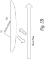
- Figure 5B shows an embodiment where the transducers are positioned behind (e.g. proximal to) the front surface of the patient pad 230 and are oriented in a desired direction with a ramp formed 238 on the rear/proximal surface of the patient pad.
- the ramp 238 is angled with respect to the front or distal surface of the patient pad such that ultrasound signals are transmitted and received in a direction that is not orthogonal to the direction of fluid flowing in a vessel of interest.
- signals are transmitted and received through the elastomeric material that makes up the patient pad and the ramp. Therefore, the elastomeric material used for the patient pad and ramp should be made of a material that is relatively transparent to ultrasound at the frequency of operation.
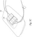
- FIG. 5C illustrates a transducer where a pair of transmit/receive elements are set in a molded patient pad of the type described in connection with Figure 5A .
- two sets of TX/RX transducers are positioned on the ramp 236 to increase the width of the transmitted and received beams.
- the ramp 236 is sized in height and width to push the transducers into a notch or recess in the subject's neck below the jaw and to the side of the trachea in a manner that the transducers are closer to the carotid and jugular vessels.
- each transducer is driven by a separate set of cables.
- the transducer elements could be wired in parallel or attached to a flex circuit as described above.
- FIGS 5D and 5E show another embodiment of a transducer in accordance with the disclosed technology.
- an ultrasound patch has a patient pad 250 formed of a flexible elastomeric sheet (molded silicone, impregnated fabric or the like) that conforms to the subject's anatomy.
- a rigid housing 260 is secured behind the patient pad 250 and contains the battery, electronics and speaker etc. that generate the ultrasound signals, detect a Doppler shift in a vessel and produce an output indicative of the Doppler shift as well as transmit the signal data to a remote device.
- the ends of the elastomeric sheet 250 can flex away from the housing 260 to conform to a subject's anatomy.
- the ramp 236 is sized to allow the transducer elements to fit within a notch between the sternocleidomastoid muscle and the trachea to be closer to the carotid artery and the jugular vein of the subject.
- the ramp is offset along the short dimension of the patient pad to provide an indication of which way round the transducer should be oriented on the subject's neck. As can be seen, the ramp is closer to one edge of the patient pad than the other while being symmetrically placed between ends on the long dimension of the patient pad so that the transducer can be positioned on either side of the neck.
- the transducer elements 240a, 240b can be oriented so they lie parallel with respect to the skin surface of the subject and a lens used to steer the signals transmitted from and received by the transducer elements in a direction away from normal due to the slight delay or advancement caused by the sound waves travelling through the thicker part of the lens depending on the lens material.
- the flex circuit extends outwardly from the PCB layers to provide a flexible connection to the front and rear surfaces of a piezoelectric transducer element.
- An airgap behind the transducer element provides an acoustic impedance mismatch to prevent/limit the rearward transmission of the ultrasound signals and reflect signals forward to increase transmission power of transducer.
- the depth of the airgap behind the transducer should be selected such that the glue used for the top PCB layer isn't drawn into the airgap by capillary forces.
- FIG. 6C is cross-sectional end view of a transducer in accordance with some embodiments of the disclosed technology.
- the transducer 270 includes a rectangular sheet of piezoelectric material, such as PZT, that is seated within a corresponding slot, aperture or cutout in a first layer 278 of PCB material such as FR4.
- a second layer 280 of flex circuit material is behind (proximal) to the first layer 278.
- the flex circuit includes a slot or aperture over a portion of the PZT sheet to form an airgap 284 that is behind the PZT material.
- a third layer of PCB material such as FR4 overlays the second layer 280 of flex circuit layer material to seal the airgap 284.
- Figure 6D is a cross-sectional view of the transducer and shows how an electrode layer is sputter coated from the flex circuit to the rear or proximal side of the PZT sheet 276 to provide an electrical contact to the PZT material.
- the third layer 282 is placed over the flex circuit layer after the sputter coating to seal the electrical connection under the third layer and to cover/seal the airgap 284.
- Figure 6E is a side view of a long edge of a transducer in accordance with some embodiments of the technology.
- the top and bottom surfaces of the PZT element is coated with a metal conductor such as gold or gold plus chromium via a sputtering or other deposition process.
- a metal conductor such as gold or gold plus chromium via a sputtering or other deposition process.
- Other conductive metals such as copper or aluminum etc. could also be used.
- the PZT sheet is plated on both flat sides and then tilted and plated on one edge so that there is a continuous electrical path from the front surface to the rear surface via the plated edge.
- Figures 6G-6K show a number of manufacturing steps that can be used to make a number of electrodes in a batch process.
- Figure 6G shows an assembly jig 294 that includes a number of rectangular recesses into which plated PZT elements are placed. Fiducial rods or pins 296 are placed on opposite corners of the jig to align the various layers and masks used in the manufacturing process.
- the jig is preferably made of a silicone impregnated plastic material that acts as a release. However, it may be useful to place a sheet of plastic wrap over the jig 294 before placing the transducer elements into the jig to prevent the transducer elements from becoming stuck in the jig.
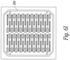
- Figure 6H shows a sheet of the first PCB layer 278 placed over the transducer elements in the jig 294.
- the first PCB layer can be secured to the jig and the PZT elements placed into the cutouts of the first layer.
- the first PCB layer 287 has as number of routed slots into which the PZT elements are fitted.
- the recesses in the jig 294 are dimensioned such that top of PZT elements and the top surface of the first PCB layer 278 are co-planer when the PZT elements are seated in the recesses of the jig.
- the glue is applied to the surface of the flex layer with a roller or the like (and the second PCB layer) in order to get a thin, even layer of glue and to avoid covering the electrodes on the PZT with glue and would interfere with creating an electrical connection to the PZT as described below.
- the assembly jig allows firm pressure to be applied evenly across the entire stack while the adhesive is curing. This helps ensure flatness, good adhesion and good sealing of the air gap.
- the next step is to place a mask (not shown) over the flex circuit layer to shield the slots in the PZT elements and the traces on the flex circuit from a sputtering process.
- the sputtering process forms a conductive path from traces surrounding the slots in the flex circuit layer to the plated transducer elements.
- the conductive path could be made with conductive ink or a conductive epoxy.
- Lens elements having different shapes such as convex 294, concave 296 or tilted concave 298 can be secured via an adhesive to the front surface of the PZT elements to focus the beam from the transducer elements.
- the lens material could be cast directly onto the surface rather than being applied with a separate adhesive.
- Such lenses can be made of silicone rubber or other materials depending on the type of focusing desired.
- Figure 6M shows an embodiment where a protective layer 300 including molded lens elements is placed over a number of adjacent transducer elements.
- the protective layer 300 covers the spaces between the transducer elements and the lenses are positioned in front of the transducer elements.
- the protective layer 300 can cushion the transducer from shocks or drops while the lens elements focuses the ultrasound in a desired direction.
- Figure 6N shows an example of a lens 302 that is over molded onto a pair of transducer elements that are set on a ramp as discussed above.
- the ramp for the transmit element may have a different angle compared with the angle of the ramp for the receive element so that the focus area for the transducer elements overlap in an area of interest.
- the lens 302 is molded over the front surface of the transducer elements to focus the ultrasound in a desired direction and can serve to protect the exposed PZT elements.
- the air-backed transducer elements are generally singular elements.
- Figures 6O and 6P show two alternative designs where a single flex circuit is connected to a pair of transducer elements.
- a flex circuit at either short end of two adjacent transducer elements joins the transducer elements so that they are hinged together.
- Figure 6P shows an embodiment 306 where a single flex circuit joins two transducer elements from the long side so that they are foldable with respect to one another.
- a transducer element 308 is round and not rectangular.
- the round PZT element is plated on both sides plus at least a portion of an edge.
- One side of the PZT transducer element includes a slot or channel to break the electrical connection from the plated first side of the PZT transducer element to the second plated side of the transducer element.
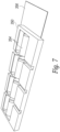
- Figure 7 shows another alternative embodiment of a frame that supports a number of transducer pairs.
- a frame 350 is molded or 3D printed to support a number of TX and RX transducer 354 elements at an angle to a front face of the transducer.
- the frame 350 supports four TX elements and four RX elements.
- the TX and RX transducer elements are supported by the frame 350 at an angle between 20 and 60 degrees with respect to a face of the transducer.
- the frame can include angled side rails in which edges of the transducer elements are fitted so that the backs of the transducer elements are open or the transducer frame can include a number of angled, acoustically transparent backing supports that support the transducer elements along their length.
- a printed flex circuit 356 includes conductors or traces (not shown) that connect to the front and rear surfaces of each transducer element.
- the frame 350 allows the rear surface of the transducer elements to be exposed (e.g. air-backed).
- a light foam material can be placed on the rear surface of the transducer elements when they are in the frame.
- the angle of the TX and RX elements is preferably set either by physically orienting the transducers in the frame or by the use of a lens or a ramp as shown in Figures 5A and 5B .
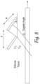
- the angle ⁇ of the transducers is set such that the Doppler angle to the flow in a vessel is between 20 and 60 degrees.
- the angle ⁇ is selected to compensate for the change in beam direction from the Snell's law effect at the transducer/tissue boundary.
- the angle of the TX and RX elements need not be the same and in some embodiments, are different so that the TX and RX beams overlap in the area of the vessel.
- the flexible phased array transducer is manufactured from a sheet of piezoelectric material 400 such as PZT or other known piezoelectric material.
- the sheet 400 starts with a thickness greater than the resonant mode thickness.
- the sheet 400 is lapped or ground to a desired thickness (e.g. about 1000 um) and is diced with a saw or patterning laser to create a number of square pillars 410 as shown in Figure 10B .
- the pillars are about 125 um on each side and are separated by 60 um kerf cuts.
- the pillars are about 500 um in height.
- other sizes could be used depending on the frequencies to be used.
- other shapes besides square pillars could be used such as triangles, pentagons, hexagons, rectangles etc. Having a large number of small pillars in the transducer allows the transducer to flex as will be described below.
- the pattern of pillars 410 is then coated with a flexible adhesive such as a flexible epoxy 430 in a manner that avoids trapping air bubbles between the pillars (e.g. under vacuum) as shown in Figure 10C .
- a flexible adhesive such as a flexible epoxy 430
- the substrate is lapped or ground on both sides to a desired thickness corresponding to the piezoelectric resonance frequency (e.g. ⁇ 500 um) as shown in Figures 10D, 10E , leaving only the pillars 410 joined by the adhesive.
- the piezoelectric resonance frequency e.g. ⁇ 500 um
- the deposited electrode metal forms fan out tabs 440 at the ends of the transducer elements to provide an electrical connection to the TX and RX elements.
- one side of the transducer has fan out tabs for all the even numbered transmit and receive elements while the other side of the transducer has the fan out tabs for the odd numbered transmit and receive elements.
- the transmit elements 430 are separated from the receive elements 432 by cutting the transmit elements from the receive elements in the piezoelectric sheet 400 with a saw or laser as shown in Figures 10I and 10J .
- the transmit and receive elements are then rejoined to create a completed phased array transducer 450 by placing an adhesive foam strip 440, soft epoxy, RTV or other dampening material between the sheet containing the transmit elements and the sheet containing the receive elements as shown in Figures 10K and 10L .
- the transducer 450 is mounted on a flex circuit 500 as shown in Figures 10M and 10N .
- the flex circuit 500 includes a pair of ZIFF connectors 510 that receive the fan out tabs of the transducer to make an electrical connection to the transmit and receive elements.
- one ZIFF connector 510 makes connections to the even numbered transmit and receive elements and the other ZIFF connector 510 makes connections to the odd numbered transmit and receive elements.
- the transducer elements are permanently bonded to the flex circuit by soldering, wire bonding or laser-welding.
- Figure 10M shows a top surface of the flex circuit 500.
- the top surface of the flex circuit 500 also includes a number of traces (not shown) that are patterned to make connections to the other circuit components (not shown) to be placed on the flex circuit.
- the flex circuit includes a number of holes 520 about its perimeter through which wires can be passed to make connections to features on the other side of the flex circuit.
- the holes 520 can be plated through or filled with a conductive material to make an electrical connection between features on the top and bottom surfaces of the flex circuit 500.
- Figure 10N shows the bottom surface of the flex circuit 500.
- the bottom surface 530 includes a rectangular opening 540 behind which the transducer 450 is placed.
- all or a majority of the bottom surface 30 of the flex circuit 500 includes a common electrode that is electrically coupled to the electrode on the front face of the transducer via one or more tabs 550 on the flex circuit and a conductive adhesive.
- the common electrode on the bottom surface of the flex circuit can be connected to components or electrodes on the top surface of the flex circuit through a conductor passed through one or more of the holes 520, via a plating or other conductive material in the holes 520 or via a conductor (wire or foil etc.) that wraps over an edge of the flex circuit 500.
- the opening 540 exposes the bottom ground electrode surface of the transducer 450 and provides an acoustic window to allow ultrasound energy to pass through.
- a spacer 560 such as a strip of adhesive foam is placed around the perimeter of a rear surface of the transducer 450.
- the spacer 560 has an opening 570 positioned over the electrodes for the transmit and receive transducer elements as shown in Figure 10O .
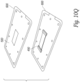
- a cover 580 is placed over the spacer 560 ( Figure 10P ) to create an air gap behind the transducer elements. With the cover 580 in place, the transducer 450 and the flex circuit 500 can be placed in a mold and encapsulated in a flexible elastomeric material 600 such as silicone as shown in Figure 10Q . Once encapsulated, ultrasound signals created by the transducer elements and the corresponding return echo signals pass through the flexible material 600.
- the transmit and receive transducer elements are formed of a number of electrically connected, piezoelectric pillars that are joined by a flexible adhesive, the transducer 450 can bend to conform to a subject's anatomy.
- the transducer can be made to be rigid.
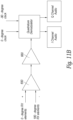
- the receive circuitry shown in Figure 11B processes the signals received by the transducer receive elements.
- signals from the 0 and 180-degree elements are applied to a differential amplifier 650 that produces a difference between the signals or equivalently, a sum of the two signals with one channel phase-shifted 180 degrees.
- the output of the difference amplifier 650 is fed to a radio frequency (RF) amplifier 660 that increases the signal strength of the difference signals.
- the output of the RF amplifier 660 is fed to a pair of demodulators (mixers and envelope detectors) that mix the signals back to baseband using the 0 and 90-degree clock signals that are used to drive the transmit elements ( Figure 11A ).
- CVP central venous pressure
- the central venous pressure waveform has been used to diagnose restrictive cardiac disease such as cardiac tamponade, constrictive pericarditis, right ventricular dysfunction, pulmonary hypertension, tricuspid regurgitation etc. Similar physiology in the hepatic veins has been used to estimate fluid responsiveness.
- the Doppler amplitude or Doppler power of the blood flowing though the carotid versus the jugular vein is compared and used to estimate central venous pressure as shown in Figure 16 .
- the Doppler power of blood flow in the carotid at some point in the cardiac cycle such as peak systole is compared with the Doppler power in the jugular at the same moment in time. If the ratio of the Doppler power in the jugular is low compared to the Doppler power in the carotid, e.g. 0.5:1, then central venous pressure is estimated to be low. On the other hand, if the ratio of the Doppler power in the jugular is high compared with the Doppler power in the carotid for example 2:1, then the central venous pressure is estimated to be high.
- the Doppler power or Doppler amplitude within the jugular relates to the size of the jugular vein compared to the size of the carotid at some point and has a relationship to CVP.
- multiple Doppler amplitude or Doppler power readings for blood flowing in the jugular (reverse flow) and carotid (forward flow) are computed and stored by a processor over a cardiac cycle. Variations of more than 1.0 over a cardiac cycle may signal an increased risk for high CVP.
- ECG signals are obtained simultaneously with the Doppler measurements to correlate the Doppler measurements with the cardiac cycle.
- a processor is programmed to analyze the variations in the Doppler amplitude or Doppler power over the cardiac cycle and compare against data from studies relating the Doppler amplitude and Doppler power variations to CVP.
- the processor may store the relationship data in a memory on the ultrasound patch.
- the processor of the ultrasound patch transmits the Doppler measurements to a remote computer over a wired or wireless link to a computer that stores the relationship data.
- Jugular venous velocity profiles may be used to estimate right heart function. Jugular venous physiology has also been validated in the superior vena cava. The Doppler venous velocity profile follows the time-course of the central venous pressure waveform.
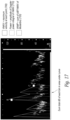
- the ratio is > 60% then normal CVP is indicated. If the ratio is between 50-60%, then rising CVP is indicated and if the ratio is ⁇ 50%, then high CVP is indicated as shown in Figure 17 .
- the particular threshold percentages may be adjusted as additional clinical data is obtained.
- measurements of the Doppler velocity profile of the jugular vein are continuously and non-invasively measured (over at least several cardiac cycles and preferably longer such as over several minutes or hours).
- the data are analyzed for systolic and diastolic peak jugular vein velocity as well as jugular vein systolic velocity time integral (VTI) relative to diastolic vein VTI as a qualitative and quantitative assessment of CVP, right ventricular function, fluid responsiveness and fluid tolerance.
- VTI jugular vein systolic velocity time integral
- jugular venous Doppler power is continuously and non-invasively monitored as a surrogate for vein diameter. Continuously monitored Doppler power throughout a respiration cycle is used as a surrogate for jugular vein size, collapsibility and therefore CVP.
- jugular venous power is continuously and non-invasively monitored and compared to carotid artery power - also measured by the same continuous wave ultrasound patch. The comparison is used as a surrogate for relative vascular diameters and compute a ratio as a qualitative estimation of CVP.
- the jugular venous waveform and Doppler power are continuously and non-invasively monitored, measured and compared to carotid power and waveform to identify venous waveform abnormalities.
- This data is provided to an artificial intelligence engine or neural network along with clinical data to continuously refine and enhance the non-invasive measurement of the CVP and detect cardiovascular abnormalities (e.g. tricuspid regurgitation) as well as to detect both fluid responsiveness and fluid tolerance.
- each method described has varying sensitivity and specificity for estimating an elevated central venous pressure.
- the method which has the greatest receiver operative curve statistic is an internal jugular vein area relative to carotid artery area of more than 2.0.
- the transducers are incorporated in a device with processing power (e.g. microprocessor or microcontroller), signal processing circuitry and memory that can record and store measurement data obtained over a period of time.
- processing power e.g. microprocessor or microcontroller
- the device includes circuitry to send the data to a remote computer system via a wired or wireless communication link.
- the data can be analyzed using artificial intelligence or other algorithms to estimate CVP.
- One aspect of the disclosed device is that it can record the aforementioned data for storage and analysis.
- the quadrature signal processing circuitry is configured to allow estimates of the fluid flow in both directions toward and away from the transducer elements corresponding to flow in the carotid and the jugular. Because transducer pairs overlap both the carotid artery and jugular vein, measurements of flow in both vessels can be simultaneously detected and analyzed.
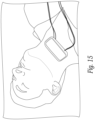
- Figure 15 shows a prototype flow measuring device in position on a subject's neck. With the elastomeric patient pad, the device is designed to be comfortable for extended subject flow monitoring.
- Figures 16A shows an anatomy in which the ramp on the bottom of some embodiments of the patient pad is designed to place the transducers near the carotid artery in a subject.
- the ramp is designed to place the transducers in the physical region between the trachea and the sternocleidomastoid muscle where tissue pliability accommodates a 10-30 mm angled wedge into the neck to create the desired Doppler angle.
- the ultrasound patch has transducers that are wide enough to produce a beam that intersects the carotid artery, the jugular vein or both.
- the disclosed technology is useful in investigating the relationship between Doppler signals detected in the carotid or other vessels and congestive heart failure.
- Congestive heart failure CHF is the most common cause of hospitalization in adults over the age of 65 years old; the burden upon the health care system of this disease is immense.
- left ventricular systolic function is ubiquitously assessed using standard echocardiography and quantified using the ejection fraction.
- an ejection fraction of less than 35-40% has major clinical implications because life-preserving pharmacological and electrophysiological therapies are indicated.
- the left ventricular ejection time is the duration (typically in milliseconds) of systole - defined on the pressure waveform from end-diastole to the dicrotic notch.
- the LVET is the duration that the aortic valve is open - ejecting blood into the arterial tree.
- there is a known, direct relationship between the LVET and ejection fraction in other words, as ejection fraction falls, so too does the LVET, in milliseconds. The relationship is robust enough that authors have advocated using the LVET to monitor heart failure therapy.
- the LVET has classically been measured using the pressure waveform, it has also been validated using the Doppler-derived spectrogram from both the left ventricular outflow tract and aorta and, quite notably, the common carotid artery. Accordingly, measurement of the common carotid ejection time has both diagnostic and therapeutic implications for the left ventricle.
- one group created an index of PEP / LVET using aortic Doppler from a transthoracic echocardiogram and found an excellent association with left ventricular ejection fraction; further, some therapies may be specifically-monitored using the PEP / LVET ratio.
- the disclosed ultrasound patch includes one or more integrated or connected ECG electrodes to detect a subject's ECG signals.
- Circuitry within the patch conditions the ECG signals for wired or wireless communication to a remote device such as an ECG detector along with ultrasound signals detected from a subject's vessel.
- a processor within the patch can also be programmed to analyze the detected ECG signals to measure the PEP, systolic ejection time, PEP/ LVET ratio as well as other combinations of electrophysiological and Doppler indices as markers of left ventricular function.
- indices have been found helpful in diagnosis of depressed left ventricular function, their diagnostic abilities are not perfect and could be refined. Additionally, other aspects of the carotid waveform may help predict cardiac ejection fraction. Artificial intelligence and machine learning could greatly improve the above-mentioned predictive metrics pulled from a wearable ultrasound patch with integrated ECG functionality. Additional, cryptic indices could be assessed and analyzed with respect to cardiac function, given that the morphology of the Doppler waveform is also determined by downstream vascular impedance. Artificial intelligence may serve to pull out the effects of both cardiac function and vascular impedance on the pulse of a major artery like the carotid.
- the ultrasound patch described above is continuous wave, rather than pulsed wave, such that the velocity profiles of the entire carotid lumen may be obtained.
- additional parameters such as spectral broadening and maximum-to-mean velocity profiles may be captured and scrutinized in the healthy and CHF populations.
- the maximum-to-mean velocity in the carotid during early systole/ejection is known to be nearly 1:1, i.e. adopt a 'plug like' profile. This is likely not the same with impaired cardiac contractility.
- power or amplitude profiles of the blood may change with diuretic-induced hemoconcentration or other pharmacological interventions - all such metrics may be teased apart with advanced machine learning.
- Data acquired from a wearable, continuous wave ultrasound patch over the common carotid artery may be analyzed and integrated to greatly improve both diagnostic and therapeutic facets of congestive heart failure - especially if integrated with an imbedded electrocardiogram.
- a convenient-to-apply ultrasound patch can improve access to care in underserved communities where cardiologists and echocardiographers are unavailable. By similar reasoning, remote monitoring of CHF therapy will be enhanced.
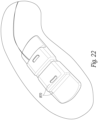
- each end of the housing for the ultrasound patch includes two openings or slots 870 on a top and side surface thereof through which a tracheostomy strap (not shown) can be passed in order to secure the patch to the subject.
- Tracheostomy straps generally include a pad that fits behind the neck and two self-adhering straps (such as hook and loop straps, e.g., Velcro ® ).
Landscapes
- Health & Medical Sciences (AREA)
- Life Sciences & Earth Sciences (AREA)
- Engineering & Computer Science (AREA)
- Physics & Mathematics (AREA)
- Molecular Biology (AREA)
- Surgery (AREA)
- Pathology (AREA)
- Radiology & Medical Imaging (AREA)
- Biophysics (AREA)
- Biomedical Technology (AREA)
- Heart & Thoracic Surgery (AREA)
- Medical Informatics (AREA)
- Veterinary Medicine (AREA)
- Nuclear Medicine, Radiotherapy & Molecular Imaging (AREA)
- Animal Behavior & Ethology (AREA)
- General Health & Medical Sciences (AREA)
- Public Health (AREA)
- Hematology (AREA)
- Acoustics & Sound (AREA)
- Computer Networks & Wireless Communication (AREA)
- Gynecology & Obstetrics (AREA)
- Cardiology (AREA)
- Ultra Sonic Daignosis Equipment (AREA)
- Measurement And Recording Of Electrical Phenomena And Electrical Characteristics Of The Living Body (AREA)
Description
- The disclosed technology relates to ultrasound devices designed to detect fluid flow in a vessel.
- In many clinical and diagnostic settings, physicians or other medical personnel often use ultrasound to assess how well blood is flowing through a subject's vasculature. Most ultrasound systems require that an operator use one hand to hold an ultrasound transducer at a particular angle to a vessel while using the other hand to control a base unit of the ultrasound imaging system, thereby preventing the performance of other tasks while measuring flow. Another approach to measuring flow is to use a dedicated ultrasound flow measuring device such as described in
PCT/CA2016/051451 US 2017-0293277 A1 andU.S. Patent Application No. 15/877,251, filed Jan. 22, 2018 U.S. 2018-0353157 A1 ). The devices described in these applications can be affixed to a subject to continuously or periodically measure flow in a vessel thereby freeing up the hands of the caregiver. - The disclosed technology relates to improvements in the design of the transducers for use in such a dedicated ultrasound flow measuring device (also referred to as an ultrasound patch) and for use of such a flow measuring device to measure flow in a vessel, changes in velocity to estimate changes in vessel diameter and central venous pressure (CVP), and changes to detect a relationship between Doppler flow and hemodynamic pathologies including sepsis, shock and congestive heart failure (CHF).
WO 2018/102911 A1 discloses a device for automatically assessing functional hemodynamic properties of a patient is provided, the device comprising: a housing; an ultrasound unit coupled to the housing and adapted for adducing ultrasonic waves into the patient at a vessel; a detector adapted to sense signals obtained as a result of adducing ultrasonic waves into the patient at the vessel and to record the; and a processor adapted for receiving the recorded signals as data and transforming the data for output at an interface. Other devices, systems, methods, and/or computer-readable media may be provided in relation to assessing functional hemodynamics of a patient.
US 2017/105700 A1 discloses a system for continuous ultrasonic monitoring including an ultrasound transducer. The ultrasound transducer includes an array of ultrasonic transducer elements. The ultrasonic transducer elements are operable to steer and focus an ultrasound beam to a selectable location and to receive an ultrasound signal from the selectable location. A holder is provided for holding the ultrasound transducer, the holder being attachable to a skin surface of a patient. A controller is configured to repeatedly steer and focus the ultrasound beam to identify a target section of an object inside the body of the patient and to acquire an ultrasound image such that the target section is maintained within the acquired ultrasound image.
US 8876720 B2 discloses a device for acquiring ultrasound-generated data from a patient including a securing system and a probe configured for connection to the securing system, the probe including a base having an interfacing surface, an imaging mechanism adjustable relative to the base and configured to send and receive ultrasound signals along an imaging direction, and an adjustment mechanism configured to adjust the imaging mechanism relative to the base thereby adjusting the imaging direction. - The invention provides an ultrasound patch according to
claim 1. Optional features are set out in the dependent claims. -
-
Figures 1A and 1B are front and rear isometric views of a printed circuit board that supports an air-backed array of ultrasound transducer elements in accordance with one embodiment of the disclosed technology; -
Figures 2A and 2B are front and rear isometric views of a pair of piezoelectric transducer elements secured to the printed circuit board shown inFigures 1A and 1B ; -
Figures 3A and 3B are isometric views of two different embodiments of a frame that supports the air-backed transducer elements in accordance with embodiments of the disclosed technology; -
Figure 4A shows a number of transducer frames connected with co-axial cables in accordance with an embodiment of the disclosed technology; -
Figure 4B shows a number of transducer frames connected by a flex circuit in accordance with an embodiment of the disclosed technology; -
Figure 4C is a side view of a number of electrically connected transducer frames in accordance with an embodiment of the disclosed technology; -
Figures 5A-5F show several different embodiments of a patient pad for a transducer that includes a ramp that sets an angle of the transducer elements in accordance with embodiments of the disclosed technology; -
Figures 6A-6K show a structure of an air-backed transducer and a method for manufacturing a number of air-backed transducers in accordance with some embodiments of the disclosed technology; -
Figures 6L-6N show a number of different lenses that can be secured to the front of a transducer in accordance with some embodiments of the disclosed technology; -
Figures 6O-6Q show alternative air-backed transducer configurations in accordance with some embodiments of the disclosed technology; -
Figure 7 shows a frame for supporting transducer elements at an angle in accordance with another embodiment of the disclosed technology; -
Figure 8 shows one orientation of a pair of transmit/receive transducer elements with respect to a vessel in order to detect a Doppler shift in the ultrasound signals that are directed to the vessel; -
Figure 9 shows a number of measured beam plots for a transducer constructed in accordance with one embodiment of the disclosed technology; -
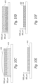
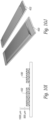
Figures 10A-10Q illustrate a number of manufacturing steps to fabricate a flexible phased array transducer in accordance with some embodiments of the disclosed technology; -
Figure 11A is a block diagram of a portion of a transmit circuit for driving elements of a phased array transducer in accordance with some embodiments of the disclosed technology; -
Figure 11B is a block diagram of a portion of a receive circuit to detect Doppler signals from a phased array transducer in accordance with some embodiments of the disclosed technology; -
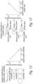
Figure 12 is a graph of a variability in internal jugular vein diameter versus central venous pressure (CVP) during a cardiac cycle; -
Figure 13 is a graph of a ratio of internal jugular and carotid Doppler powers versus central venous pressure; -
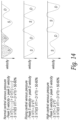
Figure 14 are graphs of systolic and diastolic venous flow velocity time integrals (VTI) away from a transducer during cardiac cycles for normal, rising and high central venous pressures; -
Figure 15 illustrates a prototype ultrasound flow measuring device in position over the carotid artery of a subject; -
Figures 16 is an anatomical illustration showing a physical area in which the flow measuring device in accordance with some embodiments of the disclosed technology is placed; -
Figure 17 shows a Doppler scan and measurements made in accordance with an embodiment of the disclosed technology; -
Figure 18 shows how Doppler power and VAMP measurements track VMAX in a resting state in accordance with an embodiment of the disclosed technology; -
Figure 19 shows how Doppler power and VAMP measurements vary with a fluid intervention in accordance with an embodiment of the disclosed technology; -
Figure 20A shows a relationship between an ECG signal and a Doppler velocity waveform andFigure 20B shows an ultrasound patch with ECG electrodes to detect an ECG signal in accordance with some embodiments of the disclosed technology; -
Figure 21 is a block diagram of a system including an ultrasound patch with one or more ECG electrodes that provide an ECG signal to an ECG recorder to correlate detected Doppler signals with ejection fraction or other cardiac output measures in accordance with some embodiments of the disclosed technology; and -
Figure 22 shows an embodiment of an ultrasound patch with slots in a housing to receive a strap that secures the patch to a subject in accordance with some embodiments of the disclosed technology. - The disclosed technology relates to improved transducer designs for use with an ultrasound patch device that is configured to detect flow in a vessel. As will be discussed in detail below, in some embodiments, the transducers include air or foam-backed piezoelectric elements that produce ultrasonic acoustic energy for delivery towards a vessel and produce electronic signals from the corresponding acoustic echo signals received.
-
Figures 1A and 1B are isometric front and back views of a printedcircuit board 20 that is configured to support a pair of piezoelectric transducer elements. In one embodiment, thecircuit board 20 is rectangular and includes a pair of spaced, parallelmilled slots hole holes circuit board 20 is about 3 cm. on each side although the printed circuit board could be made larger or smaller. - In the embodiment shown, a top surface of the printed
circuit board 20 includes acommon ground electrode 26 made of a conductive material such as gold, copper or aluminum. In the embodiment show, the common ground electrode covers the entire top surface of the printed circuit board except for the area of the milled slots 22. A pair of through holes orvias -
Figure 1B shows a rear surface of the printedcircuit board 20 shown inFigure 1A . The rear surface includes a pair ofsignal electrodes openings signal electrodes ground electrodes ground electrodes ground electrodes 26 on the front surface of the printed circuit board through thevias -
Figures 2A and 2B show the printed circuit board ofFigures 1A, 1B with a pair oftransducer elements transducers elements transducer elements Figure 2B shows the printedcircuit board 20 with thetransducer elements openings circuit board 20 with a conductive epoxy such as EPO-TEK H20E that bridges the gap between the surface of the printed circuit board and the electrodes on the PZT sheets. In other embodiments, a metal foil or other conductor could be used to electrically connect the traces on the printed circuit board to the electrodes on the transducer elements. In one embodiment, micro-coaxial conductors (not shown) are connected to the signal electrodes. In one embodiment, the signal electrodes for each transducer element are electrically separate while the ground electrodes on the printed circuit board and the transducer elements are commonly connected. - In the embodiment shown, the ground electrodes on the transducer elements are facing forward and the signal electrodes are on the rear surface. It will be appreciated that this could be reversed with the ground electrode on the rear surface and the signal electrodes on the front surface.
-
Figures 3A and 3B show two embodiments of a frame that supports the printed circuit board and the transducer elements. As shown inFigure 3A , aframe 100 includesbottom floor 102 and a set ofsidewalls bottom floor 102. Acenter beam 120 connects thesidewall 104 to thesidewall 108 and divides the open space between the sidewalls of the frame into afirst cavity 126a and asecond cavity 126b. In one embodiment, thecavities sidewalls holes 130 through which a micro-coaxial cable or other conductor can be passed. The top perimeter of thesidewalls circuit board 20 shown inFigures 1A, 1B ,2A, 2B . In some embodiments, the printedcircuit board 20 is held in theframe 100 with an adhesive. - In the embodiment shown in
Figure 3A , thesidewalls groove 150 on the exterior of opposingsidewalls - In the embodiment shown in
Figure 3B , aframe 170 is formed without the bottom floor. In this embodiment, theframe 170 includes fourconnected sidewalls sidewalls center beam 180 that divides the open space between the sidewalls into a pair of cavities 182a, 182b. Alip 190 around the interior of the top surface of the sidewalls is sized to receive the outer perimeter of the printed circuit board so that the printed circuit board can be secured to theframe 170 with an adhesive or the like. Thesidewall 176 also includes pair ofholes holes sidewall 176 and therefore the frame is not designed to be electrically connected to other frames. In this embodiment, because theframe 170 lacks a bottom floor, thecavities -
Figure 4A shows a number offrames flexible alignment members 198 such as flexible metal, plastic or graphite rods are positioned in the sidewall grooves of each frame to align the frames and to permit the frames to bend and conform to a curved shape of a subject's anatomy. A set of conductors such asmicro-coaxial cables -
Figure 4B shows an alternative embodiment where a series of fourframes flex circuit 210 including traces that electrically connect the transducer elements together. In one embodiment, the TX elements of each frame are electrically connected in parallel and the RX elements are electrically connected in parallel. However, traces in the flex circuit could connect to each transducer element individually. -
Figure 4C shows a side view of a series of alignedtransducer frames - In the embodiments shown in
Figures 1A, 1B ,2A, 2B ,3A, 3B ,4A, 4B and 4C , the transducer elements are flat and are aligned to transmit and receive ultrasound signals in a direction that is normal to a face of the piezoelectric sheets. As will be appreciated by those skilled in the art, it is easier to detect fluid flow in a vessel by the measuring a Doppler shift in ultrasound signals that are transmitted and received at an angle to the fluid flow being measured. If the circuit boards described above are placed directly on a subject's anatomy, the ultrasound signals will be primarily transmitted and received in a direction that is nearly orthogonal to the fluid flow in the vessel. - To steer the signals in a direction that is not orthogonal to the fluid flow, the circuit boards can be tilted at an angle to the vessel using a molded
patient pad 230 as shown inFigure 5A . Thepatient pad 230 includes a lowerskin contacting portion 232 on a bottom surface. The bottom surface of thepatient pad 230 includes aramp 236 that holds the transducer elements at an angle with respect to a direction normal to the skin surface or the bottom of the patient pad. In one embodiment, the ramp is sized to fit in a notch in a subject's neck near the carotid artery and jugular vein as will be explained in further detail below. - In one embodiment, the
ramp 236 is shaped to set a transmit/receive direction in a range from about 20-60 degrees (and preferably 30 degrees) with respect to the direction of flow in a vessel. In the embodiment shown, the direction of the transmit and receiveelements 240a, 240b are set by theramp 236 at the same angle with respect to the subject. In other embodiments, the transmit and receive elements may have separate ramps that are oriented at different angles to normal (or separate angles on the same ramp) so that the transmit and receive beam directions can be tailored as desired. - In some embodiments, the
ramp 236 is not located on the front surface of the patient pad.Figure 5B shows an embodiment where the transducers are positioned behind (e.g. proximal to) the front surface of thepatient pad 230 and are oriented in a desired direction with a ramp formed 238 on the rear/proximal surface of the patient pad. The ramp 238 is angled with respect to the front or distal surface of the patient pad such that ultrasound signals are transmitted and received in a direction that is not orthogonal to the direction of fluid flowing in a vessel of interest. In this embodiment, signals are transmitted and received through the elastomeric material that makes up the patient pad and the ramp. Therefore, the elastomeric material used for the patient pad and ramp should be made of a material that is relatively transparent to ultrasound at the frequency of operation. -
Figure 5C illustrates a transducer where a pair of transmit/receive elements are set in a molded patient pad of the type described in connection withFigure 5A . In the embodiment shown, two sets of TX/RX transducers are positioned on theramp 236 to increase the width of the transmitted and received beams. Theramp 236 is sized in height and width to push the transducers into a notch or recess in the subject's neck below the jaw and to the side of the trachea in a manner that the transducers are closer to the carotid and jugular vessels. In the embodiment shown, each transducer is driven by a separate set of cables. However, the transducer elements could be wired in parallel or attached to a flex circuit as described above. -
Figures 5D and 5E show another embodiment of a transducer in accordance with the disclosed technology. In this embodiment, an ultrasound patch has apatient pad 250 formed of a flexible elastomeric sheet (molded silicone, impregnated fabric or the like) that conforms to the subject's anatomy. Arigid housing 260 is secured behind thepatient pad 250 and contains the battery, electronics and speaker etc. that generate the ultrasound signals, detect a Doppler shift in a vessel and produce an output indicative of the Doppler shift as well as transmit the signal data to a remote device. As can be seen inFigure 5E , the ends of theelastomeric sheet 250 can flex away from thehousing 260 to conform to a subject's anatomy. - The front face of the
patient pad 250 includes aramp 236 that is molded thereon and that supports the TX/RX transducer elements at an angle (e.g. between 20 and 60 degrees) with respect to the front face of the patient pad. The ramp includes a recess 252 into which a circuit board of the type shown inFigures 1A and 1B can be fitted.Holes 258 within the recess 252 extend through the ramp and the patient pad to allow micro-coaxial wires or other conductors to reach the transducer elements through the body of the ramp. In some embodiments, theramp 236 is wide enough to support two or more pairs of transducer elements side by side. In other embodiments, theramp 236 is sized to hold a single pair of TX and RX transducer elements. In the embodiment shown, theramp 236 is sized to allow the transducer elements to fit within a notch between the sternocleidomastoid muscle and the trachea to be closer to the carotid artery and the jugular vein of the subject. -
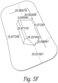
Figure 5F provides CAD measurements of a patient pad including a ramp to support transducer elements at 30 degrees in accordance with one embodiment of the disclosed technology. The 30-degree angle is selected to create a Doppler shift angle of between 45 and 60 degrees with respect to the carotid and jugular vessels in most subjects depending on their anatomy. The patient pad is preferably made of a compliant material such as molded silicon while the transducer elements are mounted on rigid printed circuit boards to allow them to be pointed towards the carotid and jugular vessels. The placement of the ramp on the surface of the patient pad is symmetric so that the pad can be placed on either side of the subject's neck. In one embodiment, the ramp is offset along the short dimension of the patient pad to provide an indication of which way round the transducer should be oriented on the subject's neck. As can be seen, the ramp is closer to one edge of the patient pad than the other while being symmetrically placed between ends on the long dimension of the patient pad so that the transducer can be positioned on either side of the neck. - In some embodiments, the
transducer elements 240a, 240b can be oriented so they lie parallel with respect to the skin surface of the subject and a lens used to steer the signals transmitted from and received by the transducer elements in a direction away from normal due to the slight delay or advancement caused by the sound waves travelling through the thicker part of the lens depending on the lens material. -
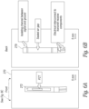
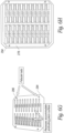
Figures 6A-6J show an embodiment of an air-backedultrasound transducer 270 that can be made in batches in accordance with some embodiments of the disclosed technology.Figures 6A shows the front ordistal side 272 of a transducer andFigure 6B shows the rear or proximal side 274 of the transducer. In some embodiments, the transducer comprises a sandwich structure of a first layer, a middle layer and a second layer where the middle layer has an aperture therein that lies behind the transducer element to form an air gap that is sealed by the second layer. In one embodiment the first and second layers are made of printed circuit board (PCB) material such as FR4 and the middle layer is a layer of flex circuit. However, other materials could be used. The flex circuit extends outwardly from the PCB layers to provide a flexible connection to the front and rear surfaces of a piezoelectric transducer element. An airgap behind the transducer element provides an acoustic impedance mismatch to prevent/limit the rearward transmission of the ultrasound signals and reflect signals forward to increase transmission power of transducer. The depth of the airgap behind the transducer should be selected such that the glue used for the top PCB layer isn't drawn into the airgap by capillary forces. -
Figure 6C is cross-sectional end view of a transducer in accordance with some embodiments of the disclosed technology. Thetransducer 270 includes a rectangular sheet of piezoelectric material, such as PZT, that is seated within a corresponding slot, aperture or cutout in afirst layer 278 of PCB material such as FR4. Asecond layer 280 of flex circuit material is behind (proximal) to thefirst layer 278. The flex circuit includes a slot or aperture over a portion of the PZT sheet to form anairgap 284 that is behind the PZT material. A third layer of PCB material such as FR4 overlays thesecond layer 280 of flex circuit layer material to seal theairgap 284. -
Figure 6D is a cross-sectional view of the transducer and shows how an electrode layer is sputter coated from the flex circuit to the rear or proximal side of thePZT sheet 276 to provide an electrical contact to the PZT material. Thethird layer 282 is placed over the flex circuit layer after the sputter coating to seal the electrical connection under the third layer and to cover/seal theairgap 284. -
Figure 6E is a side view of a long edge of a transducer in accordance with some embodiments of the technology. In the embodiment shown, the top and bottom surfaces of the PZT element is coated with a metal conductor such as gold or gold plus chromium via a sputtering or other deposition process. Other conductive metals such as copper or aluminum etc. could also be used. The PZT sheet is plated on both flat sides and then tilted and plated on one edge so that there is a continuous electrical path from the front surface to the rear surface via the plated edge. The PZT sheet also includes a slot orchannel 292 cut on the top or bottom surface with a dicing saw or laser to break the electrical connection on one of the top or bottom surfaces so that an electrical connection can be made to both the top and bottom surfaces of the PZT element from the same side. In other embodiments, the slot orchannel 292 could be made by masking a channel feature when the PZT sheet is sputter coated or screen printed etc. -
Figure 6F shows a sheet ofPZT material 276 that is plated on atop surface 276a, aside edge 276b and a bottom surface (not shown). Theslot 292 breaks the electrical connection between thetop surface 276a and the bottom surface via the plating on the edge. The sheet can be cut lengthwise along the dotted lines with a dicing saw or a patterning laser to form a number of individual PZT transducer elements. -
Figures 6G-6K show a number of manufacturing steps that can be used to make a number of electrodes in a batch process.Figure 6G shows anassembly jig 294 that includes a number of rectangular recesses into which plated PZT elements are placed. Fiducial rods or pins 296 are placed on opposite corners of the jig to align the various layers and masks used in the manufacturing process. The jig is preferably made of a silicone impregnated plastic material that acts as a release. However, it may be useful to place a sheet of plastic wrap over thejig 294 before placing the transducer elements into the jig to prevent the transducer elements from becoming stuck in the jig. -
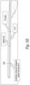
Figure 6H shows a sheet of thefirst PCB layer 278 placed over the transducer elements in thejig 294. Alternatively, the first PCB layer can be secured to the jig and the PZT elements placed into the cutouts of the first layer. The first PCB layer 287 has as number of routed slots into which the PZT elements are fitted. The recesses in thejig 294 are dimensioned such that top of PZT elements and the top surface of thefirst PCB layer 278 are co-planer when the PZT elements are seated in the recesses of the jig. - The next step is to glue a
flex layer 280 to thefirst PCB layer 278 as shown inFigure 6I . The flex layer has circuit traces formed therein and includes elongated slots or apertures that are positioned to align with a portion of the PZT elements. The dimensions of the slots/apertures in the flex layer define the dimensions of the airgaps to be formed behind the PZT elements. The dimensions of the slots in the flex layer are slightly smaller than the size of the PZT elements so that the edges of the slots lie over the back the PZT elements and can be secured to the PZT elements with an adhesive. In one technique the glue is applied to the surface of the flex layer with a roller or the like (and the second PCB layer) in order to get a thin, even layer of glue and to avoid covering the electrodes on the PZT with glue and would interfere with creating an electrical connection to the PZT as described below. The assembly jig allows firm pressure to be applied evenly across the entire stack while the adhesive is curing. This helps ensure flatness, good adhesion and good sealing of the air gap. - The next step is to place a mask (not shown) over the flex circuit layer to shield the slots in the PZT elements and the traces on the flex circuit from a sputtering process. The sputtering process forms a conductive path from traces surrounding the slots in the flex circuit layer to the plated transducer elements. As an alternative to creating the conductive path with sputtering, the conductive path could be made with conductive ink or a conductive epoxy.
- After the traces in the flex circuit are electrically connected to the transducer elements, the
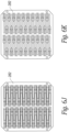
top PCB layer 282 is glued to the flex circuit layer as shown inFigure 6J . Thetop PCB layer 282 covers the slots/apertures in the flex circuit thereby sealing the airgaps behind each transducer element. After thethird PCB layer 282 is glued to theflex layer 280, the transducer elements can be separated from the jig and sawn to create individual transducers. The front face of the batch of transducers can be seen inFigure 6K . - Individual transducer elements can be fitted with a lens as shown in
Figure 6L . Lens elements having different shapes such as convex 294, concave 296 or tilted concave 298 can be secured via an adhesive to the front surface of the PZT elements to focus the beam from the transducer elements. In other embodiments, the lens material could be cast directly onto the surface rather than being applied with a separate adhesive. Such lenses can be made of silicone rubber or other materials depending on the type of focusing desired. -
Figure 6M shows an embodiment where aprotective layer 300 including molded lens elements is placed over a number of adjacent transducer elements. Theprotective layer 300 covers the spaces between the transducer elements and the lenses are positioned in front of the transducer elements. Theprotective layer 300 can cushion the transducer from shocks or drops while the lens elements focuses the ultrasound in a desired direction. -
Figure 6N shows an example of alens 302 that is over molded onto a pair of transducer elements that are set on a ramp as discussed above. As indicated above, in some embodiments, the ramp for the transmit element may have a different angle compared with the angle of the ramp for the receive element so that the focus area for the transducer elements overlap in an area of interest. Thelens 302 is molded over the front surface of the transducer elements to focus the ultrasound in a desired direction and can serve to protect the exposed PZT elements. - In the embodiments shown in
Figures 6A-6K , the air-backed transducer elements are generally singular elements.Figures 6O and 6P show two alternative designs where a single flex circuit is connected to a pair of transducer elements. InFigure 6O , a flex circuit at either short end of two adjacent transducer elements joins the transducer elements so that they are hinged together. There is a gap between the flex circuits along the length of the transducer elements.Figure 6P shows anembodiment 306 where a single flex circuit joins two transducer elements from the long side so that they are foldable with respect to one another. - In the embodiment shown in
Figure 6Q , atransducer element 308 is round and not rectangular. The round PZT element is plated on both sides plus at least a portion of an edge. One side of the PZT transducer element includes a slot or channel to break the electrical connection from the plated first side of the PZT transducer element to the second plated side of the transducer element. - The transducer elements shown in
Figures 6O-6P can be batch made with the same sandwich configuration described above. In the examples described above, the transducers include three layers. The first PCB layer is primarily used to position the PZT elements and provide stability. Therefore, in some embodiments, the first PCB layer could be omitted. Similarly, more than three layers could be used. In other embodiments, the flex circuit tabs used to connect the PZT elements could be replaced with surface mount connectors. Furthermore, a single flex circuit could be used to connect to multiple PZT elements similar to the embodiment shown inFigure 4C . -
Figure 7 shows another alternative embodiment of a frame that supports a number of transducer pairs. In this embodiment, aframe 350 is molded or 3D printed to support a number of TX andRX transducer 354 elements at an angle to a front face of the transducer. In the embodiment shown, theframe 350 supports four TX elements and four RX elements. In one embodiment, the TX and RX transducer elements are supported by theframe 350 at an angle between 20 and 60 degrees with respect to a face of the transducer. The frame can include angled side rails in which edges of the transducer elements are fitted so that the backs of the transducer elements are open or the transducer frame can include a number of angled, acoustically transparent backing supports that support the transducer elements along their length. A printedflex circuit 356 includes conductors or traces (not shown) that connect to the front and rear surfaces of each transducer element. Theframe 350 allows the rear surface of the transducer elements to be exposed (e.g. air-backed). In some embodiments, a light foam material can be placed on the rear surface of the transducer elements when they are in the frame. - In some embodiments, the
frame 350 and flex circuit are encapsulated in a material that provides a good acoustic match to the tissue to be examined such an elastomer e.g. silicone or a powder-loaded silicone. - As indicated above, the angle of the TX and RX elements is preferably set either by physically orienting the transducers in the frame or by the use of a lens or a ramp as shown in
Figures 5A and5B . As shown inFigure 8 , the angle α of the transducers is set such that the Doppler angle to the flow in a vessel is between 20 and 60 degrees. The angle α is selected to compensate for the change in beam direction from the Snell's law effect at the transducer/tissue boundary. The angle of the TX and RX elements need not be the same and in some embodiments, are different so that the TX and RX beams overlap in the area of the vessel. -
Figure 9 shows sample beam plots for air-backed TX and RX elements with an element size of 2.4 mm. in elevation and 12 mm. in the azimuthal direction when operated at a center frequency of 4 MHz. The beam pattern has a generally flat sheet-like shape of approximately 1 cm. thick out to a distance of 45 mm. from the transducer and a nearly uniform power across the face of the transducer to at least 30 mm. from the transducer. In one embodiment, several TX/RX transducer pairs are aligned side by side so that the flat planes of ultrasound transducers will intersect the subject's vessel regardless of variations in placement by the operator. If wired separately, the TX/RX pair producing the best signals for a vessel of interest can be selected to produce the signals that are analyzed to estimate flow in the vessel. - In some embodiments, steering the transmit and receive beams is accomplished with a flexible phased array transducer instead of physically orienting the transducer elements at an angle.
Figures 10A-10Q show a number of manufacturing steps employed to make a flexible phased array transducer that can be driven to steer the beam at a desired angle with respect to the surface of a subject's skin in order to detect Doppler signals from a vessel. The phased array disclosed is useful for measuring flow at locations where the skin is relatively flat such as on the wrist, ankle or thigh where the ramp design described above may be uncomfortable to wear for long periods of time. - In one embodiment, the flexible phased array transducer is manufactured from a sheet of
piezoelectric material 400 such as PZT or other known piezoelectric material. In one embodiment shown inFigure 10A , thesheet 400 starts with a thickness greater than the resonant mode thickness. Thesheet 400 is lapped or ground to a desired thickness (e.g. about 1000 um) and is diced with a saw or patterning laser to create a number ofsquare pillars 410 as shown inFigure 10B . In one embodiment, for a 4 MHz transducer, the pillars are about 125 um on each side and are separated by 60 um kerf cuts. The pillars are about 500 um in height. However, other sizes could be used depending on the frequencies to be used. In addition, other shapes besides square pillars could be used such as triangles, pentagons, hexagons, rectangles etc. Having a large number of small pillars in the transducer allows the transducer to flex as will be described below. - The pattern of
pillars 410 is then coated with a flexible adhesive such as aflexible epoxy 430 in a manner that avoids trapping air bubbles between the pillars (e.g. under vacuum) as shown inFigure 10C . Once the pillars are filled and the adhesive has cured, the substrate is lapped or ground on both sides to a desired thickness corresponding to the piezoelectric resonance frequency (e.g. < 500 um) as shown inFigures 10D, 10E , leaving only thepillars 410 joined by the adhesive. The result is a flexible 1-3 composite transducer. - The top and
bottom surfaces pillars 410 and adhesive are then coated with an electrode such as gold, copper, aluminum, or other conductive metal by sputter coating or other metal depositing technique as shown inFigure 10F . In one embodiment, the bottom electrode is only deposited in an active area of the transducer and not over the entire surface. Individual elements for the phased array are then formed by cutting the top electrode surface into rows. Such patterning can be with a saw, a patterning laser or by using a photolithographic technique. In the embodiment shown inFigure 10G , the transmitelements 430 are a single pillar wide so that kerf cuts or spaces in the electrode are placed between each row of pillars. In the embodiment shown, the receiveelements 432 are two pillars wide so that kerf cuts are made on every other row. The transmit elements therefore consist of a single row of pillars electrically connected by a common electrode that extends along the long dimension of the transducer face. The receive elements consist of two adjacent rows of pillar elements electrically connected by a common electrode that extends along the long dimension of the transducer face. In some embodiments, the kerf cuts for the elements remove some of the adhesive between adjacent rows of pillars. In other embodiments, such as if the element patterning is done with a laser, only the top electrode is removed in between the pillars and the majority of the adhesive is left between the adjacent rows of pillars. In other embodiments, the electrodes are not aligned with pillars such as in randomized 1-3 composites, 0-3 composites and film transducers. - In addition to forming the transducer TX and RX elements, the deposited electrode metal forms fan out
tabs 440 at the ends of the transducer elements to provide an electrical connection to the TX and RX elements. In one embodiment, one side of the transducer has fan out tabs for all the even numbered transmit and receive elements while the other side of the transducer has the fan out tabs for the odd numbered transmit and receive elements. - In some embodiments, to reduce cross-talk between the transmit and receive elements, the transmit
elements 430 are separated from the receiveelements 432 by cutting the transmit elements from the receive elements in thepiezoelectric sheet 400 with a saw or laser as shown inFigures 10I and 10J . In some embodiments, the transmit and receive elements are then rejoined to create a completed phasedarray transducer 450 by placing anadhesive foam strip 440, soft epoxy, RTV or other dampening material between the sheet containing the transmit elements and the sheet containing the receive elements as shown inFigures 10K and 10L . - Once the
transducer 450 is complete, it is mounted on aflex circuit 500 as shown inFigures 10M and 10N . In the embodiment shown, theflex circuit 500 includes a pair ofZIFF connectors 510 that receive the fan out tabs of the transducer to make an electrical connection to the transmit and receive elements. In some embodiments, oneZIFF connector 510 makes connections to the even numbered transmit and receive elements and theother ZIFF connector 510 makes connections to the odd numbered transmit and receive elements. In some embodiments, the transducer elements are permanently bonded to the flex circuit by soldering, wire bonding or laser-welding. -
Figure 10M shows a top surface of theflex circuit 500. The top surface of theflex circuit 500 also includes a number of traces (not shown) that are patterned to make connections to the other circuit components (not shown) to be placed on the flex circuit. In some embodiments, the flex circuit includes a number ofholes 520 about its perimeter through which wires can be passed to make connections to features on the other side of the flex circuit. Alternatively, theholes 520 can be plated through or filled with a conductive material to make an electrical connection between features on the top and bottom surfaces of theflex circuit 500. -
Figure 10N shows the bottom surface of theflex circuit 500. Thebottom surface 530 includes arectangular opening 540 behind which thetransducer 450 is placed. In some embodiments, all or a majority of thebottom surface 30 of theflex circuit 500 includes a common electrode that is electrically coupled to the electrode on the front face of the transducer via one ormore tabs 550 on the flex circuit and a conductive adhesive. The common electrode on the bottom surface of the flex circuit can be connected to components or electrodes on the top surface of the flex circuit through a conductor passed through one or more of theholes 520, via a plating or other conductive material in theholes 520 or via a conductor (wire or foil etc.) that wraps over an edge of theflex circuit 500. As can be seen inFigure 10N , theopening 540 exposes the bottom ground electrode surface of thetransducer 450 and provides an acoustic window to allow ultrasound energy to pass through. - To create an air backing for the pillars of the
transducer 450, aspacer 560 such as a strip of adhesive foam is placed around the perimeter of a rear surface of thetransducer 450. Thespacer 560 has anopening 570 positioned over the electrodes for the transmit and receive transducer elements as shown inFigure 10O . Acover 580 is placed over the spacer 560 (Figure 10P ) to create an air gap behind the transducer elements. With thecover 580 in place, thetransducer 450 and theflex circuit 500 can be placed in a mold and encapsulated in a flexibleelastomeric material 600 such as silicone as shown inFigure 10Q . Once encapsulated, ultrasound signals created by the transducer elements and the corresponding return echo signals pass through theflexible material 600. - Because the transmit and receive transducer elements are formed of a number of electrically connected, piezoelectric pillars that are joined by a flexible adhesive, the
transducer 450 can bend to conform to a subject's anatomy. In some embodiments, the transducer can be made to be rigid. -
Figures 11A and11B are block diagrams of a portion of a transmit and receive circuit used to drive the flexible phased array transducer described above. In one embodiment, aclock source 600 is divided by a clock divider and phase logic circuit 610 to produce four corresponding clock signals at 0, 90, 180 and 270 degrees with respect to the input clock. In one embodiment, theclock source 600 has a frequency of 16 MHz and the divided clock signals have a frequency of 4 MHz, which is the transmit frequency of some embodiments of the ultrasound patch. In one embodiment, the clock divider and phase logic 610 is implemented with D-type flip flops in a Johnson ring counter configuration. Each of the divided clock signals is amplified by a corresponding amplifier 620a-620d and applied to the rows of the transmit elements in a repeating pattern. In one embodiment, the various phase clock signals are applied to adjacent transmit elements in theorder 
- where lambda is the wavelength of the ultrasound within the propagation medium and theta is the desired Doppler angle. In another embodiment, the various phase signals are applied to adjacent transmit elements in the
order 
- where lambda is the wavelength of the ultrasound within the propagation medium and theta is the desired Doppler angle. In one embodiment, pairs of receive elements in the transducer selectively receive ultrasound energy at angles of +(45-55) and -(45-55) degrees depending on the size and spacing of the elements when the two signals are processed as if they are 180 degrees out of phase. Because no signals are being received from -(45-55) degrees, there is little or no interference with the desired signal. The element-to-element pitch 'p' with this embodiment is designed according to the following formula:

- where lambda is the wavelength of the ultrasound within the propagation medium and theta is the desired Doppler angle.
- In one embodiment, the receive circuitry shown in
Figure 11B processes the signals received by the transducer receive elements. In one embodiment, signals from the 0 and 180-degree elements are applied to adifferential amplifier 650 that produces a difference between the signals or equivalently, a sum of the two signals with one channel phase-shifted 180 degrees. The output of thedifference amplifier 650 is fed to a radio frequency (RF)amplifier 660 that increases the signal strength of the difference signals. The output of theRF amplifier 660 is fed to a pair of demodulators (mixers and envelope detectors) that mix the signals back to baseband using the 0 and 90-degree clock signals that are used to drive the transmit elements (Figure 11A ). The result is a pair of baseband I and Q channel signals that can processed with the components shown and described in Figure 32 of U.S. Patent Publication No.US 2018-0353157 A1 . Other circuits for detecting Doppler shifts from analog baseband signals could also be used. - As indicated above, one of the benefits of using a flexible phased array transducer is that it is directs and detects ultrasound signals at an angle with respect to a flat bottom surface of a patient pad. Because the bottom surface of the patient pad is generally flat and the transducer is flexible, the discomfort associated with wearing the ultrasound patch for longer periods of time is reduced. In addition, the flexibility of the transducer allows it to conform to the subject's anatomy allowing it to be used in more places than in the neck area of the subject. Finally, because of the flexibility, the transducer is also less likely to break because of accidental drops or contact etc.
- As discussed above, the ultrasound patch of the disclosed technology is useful for detecting fluid flow in a vessel (e.g. artery or vein) of a subject. The readings from the sensor provide useful information to a physician, health care professional or researcher. One measurement that can be made with the disclosed transducer is an estimation of central venous pressure (CVP).
- Measurement of the central venous pressure (CVP), or right atrial pressure is an important metric for venous congestion, particularly for the abdominal organs such as the kidney. As well, because the CVP is the back pressure for all venous returns, an elevated CVP raises the risk of venous congestion throughout the body. The central venous pressure waveform has been used to diagnose restrictive cardiac disease such as cardiac tamponade, constrictive pericarditis, right ventricular dysfunction, pulmonary hypertension, tricuspid regurgitation etc. Similar physiology in the hepatic veins has been used to estimate fluid responsiveness.
- There are numerous means of non-invasively assessing the CVP via the jugular vein which predominantly exploit measurements of the absolute diameter of the jugular vein versus respiratory variation in the jugular vein diameter as shown in
Figure 15 . The flow measuring devices of the disclosed technology measure Doppler signals that are related to vessel diameter and vessel flow. From these estimates, a correlation to central venous pressure can be made. As shown inFigure 12 , the variability of jugular vein size over the cardiac cycle has an inverse relation to central venous pressure. If the vessel changes size during the cycle by a variability of 2:1 for example, central venous pressure is low. On the other hand, if the vessel stays about the same size (variability of 0.5) then central venous pressure is higher. In another embodiment, the Doppler amplitude or Doppler power of the blood flowing though the carotid versus the jugular vein is compared and used to estimate central venous pressure as shown inFigure 16 . In this embodiment, the Doppler power of blood flow in the carotid at some point in the cardiac cycle such as peak systole, is compared with the Doppler power in the jugular at the same moment in time. If the ratio of the Doppler power in the jugular is low compared to the Doppler power in the carotid, e.g. 0.5:1, then central venous pressure is estimated to be low. On the other hand, if the ratio of the Doppler power in the jugular is high compared with the Doppler power in the carotid for example 2:1, then the central venous pressure is estimated to be high. - In the relationship shown in
Figure 13 , the Doppler power or Doppler amplitude within the jugular relates to the size of the jugular vein compared to the size of the carotid at some point and has a relationship to CVP. In one embodiment, multiple Doppler amplitude or Doppler power readings for blood flowing in the jugular (reverse flow) and carotid (forward flow) are computed and stored by a processor over a cardiac cycle. Variations of more than 1.0 over a cardiac cycle may signal an increased risk for high CVP. In some embodiments, ECG signals are obtained simultaneously with the Doppler measurements to correlate the Doppler measurements with the cardiac cycle. A processor is programmed to analyze the variations in the Doppler amplitude or Doppler power over the cardiac cycle and compare against data from studies relating the Doppler amplitude and Doppler power variations to CVP. In one embodiment, the processor may store the relationship data in a memory on the ultrasound patch. In another embodiment, the processor of the ultrasound patch transmits the Doppler measurements to a remote computer over a wired or wireless link to a computer that stores the relationship data. - Jugular venous velocity profiles may be used to estimate right heart function. Jugular venous physiology has also been validated in the superior vena cava. The Doppler venous velocity profile follows the time-course of the central venous pressure waveform.
- A continuous wave Doppler ultrasound patch of the types disclosed can be placed on the neck to continuously and non-invasively measure both internal jugular venous waveform velocity/morphology and Doppler power (i.e. amplitometry) in the jugular vein. This data is obtained continuously and integrated to give quantitative and qualitative assessments of the central venous pressure in a continuous and hands-free method. In one embodiment, estimates of normal, rising or high CVP are calculated by integrating the venous velocity (VTI) over the systolic (S) and diastolic (D) phases of the heart cycle. A ratio of the systolic VTI to the sum of the systolic and diastolic VTI's is used as a guide to CVP.
- In one embodiment, if the ratio is > 60% then normal CVP is indicated. If the ratio is between 50-60%, then rising CVP is indicated and if the ratio is < 50%, then high CVP is indicated as shown in
Figure 17 . The particular threshold percentages may be adjusted as additional clinical data is obtained. - In one embodiment, measurements of the Doppler velocity profile of the jugular vein (or accompanying vein next to any major artery throughout the body) are continuously and non-invasively measured (over at least several cardiac cycles and preferably longer such as over several minutes or hours). The data are analyzed for systolic and diastolic peak jugular vein velocity as well as jugular vein systolic velocity time integral (VTI) relative to diastolic vein VTI as a qualitative and quantitative assessment of CVP, right ventricular function, fluid responsiveness and fluid tolerance.
- In one embodiment, jugular venous Doppler power is continuously and non-invasively monitored as a surrogate for vein diameter. Continuously monitored Doppler power throughout a respiration cycle is used as a surrogate for jugular vein size, collapsibility and therefore CVP.
- In one embodiment, jugular venous power is continuously and non-invasively monitored and compared to carotid artery power - also measured by the same continuous wave ultrasound patch. The comparison is used as a surrogate for relative vascular diameters and compute a ratio as a qualitative estimation of CVP.
- In one embodiment, the jugular venous waveform and Doppler power are continuously and non-invasively monitored, measured and compared to carotid power and waveform to identify venous waveform abnormalities. This data is provided to an artificial intelligence engine or neural network along with clinical data to continuously refine and enhance the non-invasive measurement of the CVP and detect cardiovascular abnormalities (e.g. tricuspid regurgitation) as well as to detect both fluid responsiveness and fluid tolerance.
- In one embodiment, instantaneous changes in jugular venous waveforms and jugular Doppler power in response to provocative maneuvers such as passive leg raise, fluid administration, and intravenous contrast injection (e.g. agitated saline) are measured to help assess instantaneous cardiac preload prior to interpretation of fluid responsiveness in the carotid artery and/or diagnose cardiovascular abnormalities.
- An integrated approach to data capture and assessment is required in the device as each method described has varying sensitivity and specificity for estimating an elevated central venous pressure. For example, the method which has the greatest receiver operative curve statistic is an internal jugular vein area relative to carotid artery area of more than 2.0.
- As disclosed in
U.S. Patent Application No. 15/877,251 (U.S. Patent Publication No.US 2018-0353157 A1 ), the transducers are incorporated in a device with processing power (e.g. microprocessor or microcontroller), signal processing circuitry and memory that can record and store measurement data obtained over a period of time. The device includes circuitry to send the data to a remote computer system via a wired or wireless communication link. The data can be analyzed using artificial intelligence or other algorithms to estimate CVP. One aspect of the disclosed device is that it can record the aforementioned data for storage and analysis. The quadrature signal processing circuitry is configured to allow estimates of the fluid flow in both directions toward and away from the transducer elements corresponding to flow in the carotid and the jugular. Because transducer pairs overlap both the carotid artery and jugular vein, measurements of flow in both vessels can be simultaneously detected and analyzed. -
Figure 15 shows a prototype flow measuring device in position on a subject's neck. With the elastomeric patient pad, the device is designed to be comfortable for extended subject flow monitoring. - Figures 16A shows an anatomy in which the ramp on the bottom of some embodiments of the patient pad is designed to place the transducers near the carotid artery in a subject. The ramp is designed to place the transducers in the physical region between the trachea and the sternocleidomastoid muscle where tissue pliability accommodates a 10-30 mm angled wedge into the neck to create the desired Doppler angle. The ultrasound patch has transducers that are wide enough to produce a beam that intersects the carotid artery, the jugular vein or both.
-
Figure 17 shows a sample Doppler signal from a subject's vessel. Aline 700 on the graph shows the max flow velocity (VMAX) at each point in the cardiac cycle. Aline 710 is the Doppler power of the flow at each point. In one embodiment, the power is determined by summing the power in a number of different frequency bins (e.g. 50 Hz bins) up to the maximum frequency detected at each point in time. The power at any point in time serves as surrogate for vessel diameter. A new measurement can be made by binning frequencies under the max frequency/velocity curve per unit time. In one embodiment, the measurement, VAMP 720(also referred to as VTIP), is made by multiplying frequency/velocity bins in a given unit of time (e.g., 10ms) by the amplitude of the mode frequency in a bin to produce a surrogate measure of a number of red blood cells passing through the ultrasound beam and summing over all the bins present in the Doppler signal at that point in time. VAMP serves as a surrogate for flow in a vessel. -
Figure 18 shows how VMAX, calculated power and VAMP track during a rest state.Figure 19 shows how the calculatedpower 710 andVAMP 720 vary versusVMAX 700 during an interventional fluid event such as a leg raise. While theVMAX 700 stays relatively constant, thepower 710 andVAMP 720 measurements increase during the event and produce useful clinical information. In one embodiment, the graphs are normalized so they can all be plotted on the same chart. - In some embodiments, the disclosed technology is useful in investigating the relationship between Doppler signals detected in the carotid or other vessels and congestive heart failure. Congestive heart failure (CHF) is the most common cause of hospitalization in adults over the age of 65 years old; the burden upon the health care system of this disease is immense. In subjects with heart failure symptoms, left ventricular systolic function is ubiquitously assessed using standard echocardiography and quantified using the ejection fraction. Importantly, an ejection fraction of less than 35-40% has major clinical implications because life-preserving pharmacological and electrophysiological therapies are indicated.
- As shown in
Figure 20A , the left ventricular ejection time (LVET) is the duration (typically in milliseconds) of systole - defined on the pressure waveform from end-diastole to the dicrotic notch. In other words, the LVET is the duration that the aortic valve is open - ejecting blood into the arterial tree. Interestingly, there is a known, direct relationship between the LVET and ejection fraction; in other words, as ejection fraction falls, so too does the LVET, in milliseconds. The relationship is robust enough that authors have advocated using the LVET to monitor heart failure therapy. While the LVET has classically been measured using the pressure waveform, it has also been validated using the Doppler-derived spectrogram from both the left ventricular outflow tract and aorta and, quite notably, the common carotid artery. Accordingly, measurement of the common carotid ejection time has both diagnostic and therapeutic implications for the left ventricle. - In addition to the LVET, the aortic pre-ejection phase (PEP) has also been measured as a marker of left ventricular function. The PEP is measured as the duration - again in milliseconds - from the onset of systole on the ECG, to the upstroke in the aortic pressure waveform. As above, the PEP has also been validated using Doppler velocity in the aorta. Contrary to the LVET, the PEP has an inverse relationship with left ventricular function; that is, as the duration from the electrocardiographic impulse to the mechanical impulse rises, cardiac function is notably poorer. Given that the PEP is indirectly related to cardiac function while the LVET is directly related to cardiac function, one group created an index of PEP / LVET using aortic Doppler from a transthoracic echocardiogram and found an excellent association with left ventricular ejection fraction; further, some therapies may be specifically-monitored using the PEP / LVET ratio.
- As shown in
Figure 20B , in some embodiments, the disclosed ultrasound patch includes one or more integrated or connected ECG electrodes to detect a subject's ECG signals. Circuitry within the patch conditions the ECG signals for wired or wireless communication to a remote device such as an ECG detector along with ultrasound signals detected from a subject's vessel. A processor within the patch can also be programmed to analyze the detected ECG signals to measure the PEP, systolic ejection time, PEP/ LVET ratio as well as other combinations of electrophysiological and Doppler indices as markers of left ventricular function. - While the above-mentioned indices have been found helpful in diagnosis of depressed left ventricular function, their diagnostic abilities are not perfect and could be refined. Additionally, other aspects of the carotid waveform may help predict cardiac ejection fraction. Artificial intelligence and machine learning could greatly improve the above-mentioned predictive metrics pulled from a wearable ultrasound patch with integrated ECG functionality. Additional, cryptic indices could be assessed and analyzed with respect to cardiac function, given that the morphology of the Doppler waveform is also determined by downstream vascular impedance. Artificial intelligence may serve to pull out the effects of both cardiac function and vascular impedance on the pulse of a major artery like the carotid.
- In some embodiments, the ultrasound patch described above is continuous wave, rather than pulsed wave, such that the velocity profiles of the entire carotid lumen may be obtained. With this enriched data, additional parameters such as spectral broadening and maximum-to-mean velocity profiles may be captured and scrutinized in the healthy and CHF populations. For example, in healthy adults the maximum-to-mean velocity in the carotid during early systole/ejection is known to be nearly 1:1, i.e. adopt a 'plug like' profile. This is likely not the same with impaired cardiac contractility. Additionally, power or amplitude profiles of the blood may change with diuretic-induced hemoconcentration or other pharmacological interventions - all such metrics may be teased apart with advanced machine learning.
- To investigate these relationships, some embodiments of the ultrasound patch include integrated or connected ECG electrodes to measure a subject's electrocardiogram. As shown in
Figure 21 , theultrasound patch 800 includes one or moreintegrated ECG electrodes 810 and may be connected to one or moreremote ECG electrodes 812. ECGsignal detection circuitry 820 within the ultrasound patch receives and conditions ECG signals captured by the electrodes. In some embodiments, a processor (not shown) analyzes the signals to measure portions of the signals such as PEP, systolic ejection time etc.Ultrasound detection circuitry 830 captures Doppler signals from a vessel of interest. The Doppler and ECG signals are transmitted via a wired orwireless communication circuit 840 to a remote device such as anECG recorder 850. In some embodiments, the Doppler and ECG data are analyzed by anartificial intelligence engine 860 that is programmed to correlate Doppler and EGC signals with CHF or other medical conditions. - Data acquired from a wearable, continuous wave ultrasound patch over the common carotid artery may be analyzed and integrated to greatly improve both diagnostic and therapeutic facets of congestive heart failure - especially if integrated with an imbedded electrocardiogram. A convenient-to-apply ultrasound patch can improve access to care in underserved communities where cardiologists and echocardiographers are unavailable. By similar reasoning, remote monitoring of CHF therapy will be enhanced.
- In some embodiments, the ultrasound patch is to remain on a subject for a period of time and can be prone to coming out of contact with the subject's skin. In one embodiment shown in
Figure 22 , each end of the housing for the ultrasound patch includes two openings orslots 870 on a top and side surface thereof through which a tracheostomy strap (not shown) can be passed in order to secure the patch to the subject. Tracheostomy straps generally include a pad that fits behind the neck and two self-adhering straps (such as hook and loop straps, e.g., Velcro®). Theslots 870 on the ends of the housing allow the straps to be passed through a corner of the housing and folded and secured back on themselves to secure the patch against a subject's neck (or other anatomy such as the wrist, thigh, knee, ankle, etc.). Other configurations to secure the strap besides an opening could be used such as a bar extending outwardly from the housing that the strap can fit underneath if it is desirable to maintain a waterresistant housing. - From the foregoing, it will be appreciated that specific embodiments of the invention have been described herein for purposes of illustration, but that various modifications may be made without deviating from the scope of the invention. Accordingly, the invention is not limited except as by the appended claims.
Claims (9)
- An ultrasound patch configured for use on the skin of a patient to detect fluid flow in a vessel in the patient, comprising:one or more piezoelectric transmit elements (240a);one or more piezoelectric receive elements (240b) adjacent the one or more piezoelectric transmit elements (240a);a rigid housing (260) including a top surface and a bottom surface opposite the top surface, the top surface configured to face away from the skin of the patient and the bottom surface configured to face toward the skin of the patient during use with the patient;a flexible patient pad (250) secured to the rigid housing and including a patient contacting surface configured to conform to the patient's anatomy and a ramp (236) that extends outwardly from the patient contacting surface and supports the one or more piezoelectric transmit and receive elements (240a, 240b) at an angle with respect to a plane of the patient contacting surface of the patient pad, such that the one or more piezoelectric transmit and receive elements (240a) are positioned to transmit and receive ultrasound in a direction toward the vessel in the patient, wherein the direction is not orthogonal to the direction of fluid flowing in a vessel of interest.
- The ultrasound patch of claim 1, wherein the angle is about 30 degrees.
- The ultrasound patch of claim 1, wherein ramp comprises separate ramps that support the transmit and receive elements at different angles.
- The ultrasound patch of claim 1, wherein the one or more piezoelectric transmit and receive elements (240a, 240b) are mounted to a circuit board having a slot behind the one or more piezoelectric transmit and receive elements (240a, 240b) to provide an air gap behind the one or more piezoelectric transmit and receive elements (240a, 240b) and wherein the ramp (236) includes a recess into which the circuit board is fitted.
- The ultrasound patch of claim 1, wherein the ramp (236) is sized to fit within a space between a sternocleidomastoid muscle and a trachea of the patient and is symmetrically placed on the patient pad enabling placement on both sides of the patient's neck.
- The ultrasound patch of claim 1, further comprising one or more electrocardiogram (ECG) electrodes that are configured to detect an ECG signal from the patient.
- The ultrasound patch of claim 1, further comprising ECG signal detection circuitry configured to detect an ECG signal from a remote ECG electrode on the patient.
- The ultrasound patch of claim 7, further comprising:ultrasound detection circuitry configured to capture Doppler signals from the vessel; anda communication circuit configured to transmit the ECG signal and the Doppler signals to a remote device.
- The ultrasound patch of claim 1, further comprising a processor that is configured to detect a power of Doppler flow in an artery and a power of Doppler flow in a vein and to compare the powers as an estimate of central venous pressure.
Applications Claiming Priority (3)
| Application Number | Priority Date | Filing Date | Title |
|---|---|---|---|
| US201862699571P | 2018-07-17 | 2018-07-17 | |
| US16/377,028 US11109831B2 (en) | 2018-07-17 | 2019-04-05 | Ultrasound patch for detecting fluid flow |
| PCT/CA2019/050918 WO2020014771A1 (en) | 2018-07-17 | 2019-07-03 | Ultrasound patch for detecting fluid flow |
Publications (4)
| Publication Number | Publication Date |
|---|---|
| EP3823536A1 EP3823536A1 (en) | 2021-05-26 |
| EP3823536A4 EP3823536A4 (en) | 2022-04-13 |
| EP3823536B1 true EP3823536B1 (en) | 2025-04-09 |
| EP3823536C0 EP3823536C0 (en) | 2025-04-09 |
Family
ID=69160924
Family Applications (1)
| Application Number | Title | Priority Date | Filing Date |
|---|---|---|---|
| EP19838308.5A Active EP3823536B1 (en) | 2018-07-17 | 2019-07-03 | Ultrasound patch for detecting fluid flow |
Country Status (5)
| Country | Link |
|---|---|
| US (3) | US11109831B2 (en) |
| EP (1) | EP3823536B1 (en) |
| JP (2) | JP7202039B2 (en) |
| CN (1) | CN112739270B (en) |
| WO (1) | WO2020014771A1 (en) |
Families Citing this family (20)
| Publication number | Priority date | Publication date | Assignee | Title |
|---|---|---|---|---|
| WO2019169508A1 (en) | 2018-03-09 | 2019-09-12 | 1929803 Ontario Corp. D/B/A Flosonics Medical | Dynamically controllable patient fluid control device |
| US11109831B2 (en) | 2018-07-17 | 2021-09-07 | 1929803 Ontario Corp, (o/a FloSonics Medical) | Ultrasound patch for detecting fluid flow |
| US11779302B2 (en) * | 2018-10-20 | 2023-10-10 | Massachusetts Institute Of Technology | Methods and apparatus for imaging with conformable ultrasound patch |
| WO2021029401A1 (en) * | 2019-08-14 | 2021-02-18 | テイクティ有限会社 | Vibration-generating device |
| US12667286B2 (en) * | 2020-06-16 | 2026-06-30 | Abbott Diabetes Care Inc. | Analyte sensors featuring working electrode asperity planing for decreasing interferent signal |
| US11937976B2 (en) | 2020-07-06 | 2024-03-26 | 1929803 Ontario Corp | Ultrasound patch with integrated flexible transducer assembly |
| CA3182587A1 (en) | 2020-07-08 | 2022-01-13 | Stephen OJA | Analyte sensors featuring enhancements for decreasing interferent signal |
| CN116897015A (en) | 2020-12-23 | 2023-10-17 | 雅培糖尿病护理公司 | Analyte sensors and methods with reduced interference signal |
| CN113304339B (en) * | 2021-04-16 | 2022-10-18 | 顺德职业技术学院 | Arteriovenous fistula monitoring bracelet and equipment |
| EP4326157A4 (en) * | 2021-04-19 | 2025-01-15 | Veintech Pty Ltd | PORTABLE ULTRASOUND DEVICE AND METHOD FOR ULTRASOUND IMAGING |
| JP7666217B2 (en) * | 2021-08-05 | 2025-04-22 | セイコーエプソン株式会社 | Ultrasonic devices, ultrasonic diagnostic equipment |
| JP2024534887A (en) * | 2021-09-03 | 2024-09-26 | ソーリン シーアールエム エス ア エス | Real-time adaptation of a personalized cardiac model |
| KR102732534B1 (en) * | 2022-03-25 | 2024-11-19 | 재단법인대구경북과학기술원 | Patch with detachable and individually controllable ultrasound sensors |
| WO2023184024A1 (en) * | 2022-03-28 | 2023-10-05 | Moonrise Medical, Inc. | Systems, devices and methods for ultrasound detection of vascular hemodynamic measures |
| US12144682B2 (en) * | 2022-07-19 | 2024-11-19 | EchoNous, Inc. | Automation-assisted venous congestion assessment in point of care ultrasound |
| EP4342387A1 (en) * | 2022-09-23 | 2024-03-27 | Koninklijke Philips N.V. | Fluid responsiveness using ultrasound data |
| CN116549015A (en) * | 2023-04-26 | 2023-08-08 | 武汉大学 | Wearable device for ultrasound detection of knee joint movement and blood flow changes |
| EP4487784B1 (en) | 2023-07-05 | 2026-02-25 | GAMPT mbH, Gesellschaft für Angewandte Medizinische Physik und Technik | Ultrasonic blood flow measurement for blood vessel |
| US20250031577A1 (en) * | 2023-07-18 | 2025-01-23 | GE Precision Healthcare LLC | Integrated ultrasonic transducer microelectronic assembly method, ultrasound probe, and system |
| US12690840B2 (en) * | 2023-11-10 | 2026-07-28 | 1929803 Ontario Corp. | Ultrasound patch with integrated flexible transducer assembly |
Family Cites Families (97)
| Publication number | Priority date | Publication date | Assignee | Title |
|---|---|---|---|---|
| US4103679A (en) | 1977-03-22 | 1978-08-01 | Biosonics, Inc. | Method and apparatus for measuring blood flow noninvasively |
| DK139085B (en) * | 1977-04-19 | 1978-12-11 | Brueel & Kjaer As | Accelerometer. |
| JPS58118739A (en) * | 1982-01-05 | 1983-07-14 | テルモ株式会社 | Ultasonic probe and production thereof |
| EP0208771A4 (en) | 1985-01-15 | 1988-03-03 | Applied Biometrics | Method and apparatus for measuring arterial blood flow. |
| FR2585944B1 (en) | 1985-08-12 | 1988-07-08 | Alvar Electronic Sa | IMPLANTABLE ULTRASOUND PROBE AND ITS MANUFACTURING PROCESS |
| US5113867A (en) | 1990-05-16 | 1992-05-19 | Janszen David A | Fluid flow characterizing |
| JP3208845B2 (en) * | 1992-06-16 | 2001-09-17 | 松下電器産業株式会社 | Ultrasonic probe |
| JPH07124159A (en) * | 1993-10-29 | 1995-05-16 | Toshiba Corp | Ultrasonic probe and manufacturing method thereof |
| US6398734B1 (en) * | 1997-10-14 | 2002-06-04 | Vascusense, Inc. | Ultrasonic sensors for monitoring the condition of flow through a cardiac valve |
| US7004924B1 (en) | 1998-02-11 | 2006-02-28 | Nxstage Medical, Inc. | Methods, systems, and kits for the extracorporeal processing of blood |
| IL127112A0 (en) | 1998-11-18 | 1999-09-22 | Biosonix Ltd | System for measuring flow and method therefor |
| US6142946A (en) | 1998-11-20 | 2000-11-07 | Atl Ultrasound, Inc. | Ultrasonic diagnostic imaging system with cordless scanheads |
| IL129461A0 (en) | 1999-04-15 | 2000-02-29 | F R A Y Project Dev Ltd | 3-D ultrasound imaging system |
| US6554774B1 (en) | 2000-03-23 | 2003-04-29 | Tensys Medical, Inc. | Method and apparatus for assessing hemodynamic properties within the circulatory system of a living subject |
| US20070016046A1 (en) | 2000-09-29 | 2007-01-18 | New Health Sciences, Inc. | Systems and methods for using dynamic vascular assessment to distinguish among vascular states and for investigating intracranial pressure |
| US6755789B2 (en) * | 2002-02-05 | 2004-06-29 | Inceptio Medical Technologies, Llc | Ultrasonic vascular imaging system and method of blood vessel cannulation |
| DE60329986D1 (en) * | 2002-03-15 | 2009-12-24 | Bjorn A J Angelsen | ULTRASONIC DISPLAY OF OBJECTS IN MULTIPLE SCANEBENES |
| EP1808674B1 (en) | 2002-06-04 | 2012-05-23 | The Tokyo Electric Power Company Incorporated | Doppler type ultrasonic flowmeter, flow rate measuring method using doppler type ultrasonic flowmeter and flow rate measuring program used in this doppler type ultrasonic flowmeter |
| US20040116969A1 (en) | 2002-08-26 | 2004-06-17 | Owen James M. | Pulse detection using patient physiological signals |
| US20060135940A1 (en) | 2003-01-06 | 2006-06-22 | The Trustees Of Columbia | Programmed pulsed infusion methods and devices |
| US6843771B2 (en) | 2003-01-15 | 2005-01-18 | Salutron, Inc. | Ultrasonic monitor for measuring heart rate and blood flow rate |
| JP2004344564A (en) | 2003-05-26 | 2004-12-09 | Aloka Co Ltd | Ultrasonic diagnostic equipment |
| US7109642B2 (en) * | 2003-11-29 | 2006-09-19 | Walter Guy Scott | Composite piezoelectric apparatus and method |
| US7542188B2 (en) * | 2004-01-20 | 2009-06-02 | National University Of Singapore | Optical scanning using vibratory diffraction gratings |
| US20070222339A1 (en) * | 2004-04-20 | 2007-09-27 | Mark Lukacs | Arrayed ultrasonic transducer |
| EP1791471A1 (en) | 2004-09-13 | 2007-06-06 | Koninklijke Philips Electronics N.V. | Method and apparatus for measuring and/or detecting flow behavior of a body fluid using ultrasound |
| JP4746302B2 (en) * | 2004-10-05 | 2011-08-10 | オリンパス株式会社 | Ultrasonic probe |
| US7798970B2 (en) * | 2004-11-17 | 2010-09-21 | Salutron, Inc | Ultrasonic monitor for measuring blood flow and pulse rates |
| US7857763B2 (en) * | 2005-02-08 | 2010-12-28 | Alan Chi-Chung Tai | Automatic signal-optimizing transducer assembly for blood flow measurement |
| JP2008534071A (en) | 2005-03-23 | 2008-08-28 | ニュー・ヘルス・サイエンシーズ・インコーポレイテッド | System and method for discrimination between vascular conditions using dynamic vascular assessment and for investigation of intracranial pressure |
| US7815575B2 (en) * | 2005-05-09 | 2010-10-19 | Salutron, Inc. | Ultrasonic monitor with a biocompatible oil based transmission medium |
| US8162837B2 (en) | 2005-06-13 | 2012-04-24 | Spentech, Inc. | Medical doppler ultrasound system for locating and tracking blood flow |
| CA2627927A1 (en) * | 2005-11-02 | 2007-06-14 | Visualsonics Inc. | Arrayed ultrasonic transducer |
| JP2009515631A (en) * | 2005-11-17 | 2009-04-16 | コーニンクレッカ フィリップス エレクトロニクス エヌ ヴィ | CPR guided by blood flow measurements |
| CN101375178A (en) | 2006-01-27 | 2009-02-25 | 皇家飞利浦电子股份有限公司 | Automated ultrasonic Doppler measurement |
| JP5254043B2 (en) | 2006-02-22 | 2013-08-07 | ヘンリー フォード ヘルス システム | Topical citrate anticoagulant delivery system and method to extracorporeal blood circuit |
| US7539533B2 (en) | 2006-05-16 | 2009-05-26 | Bao Tran | Mesh network monitoring appliance |
| JP5551936B2 (en) * | 2006-09-29 | 2014-07-16 | コーニンクレッカ フィリップス エヌ ヴェ | Hands-free ultrasonic diagnostic equipment |
| ATE515978T1 (en) | 2006-10-26 | 2011-07-15 | Cardiogal Ltd | NON-INVASIVE HEART PARAMETERS MEASUREMENT |
| KR20090094447A (en) * | 2006-12-20 | 2009-09-07 | 코닌클리케 필립스 일렉트로닉스 엔.브이. | Multi-beam transmit separation |
| US9380992B2 (en) | 2007-03-30 | 2016-07-05 | General Electric Company | Method and apparatus for measuring flow in multi-dimensional ultrasound |
| CN101677807A (en) | 2007-06-01 | 2010-03-24 | 皇家飞利浦电子股份有限公司 | Wireless ultrasound probe with audible indicator |
| JP5294998B2 (en) * | 2008-06-18 | 2013-09-18 | キヤノン株式会社 | Ultrasonic probe, photoacoustic / ultrasonic system including the ultrasonic probe, and specimen imaging apparatus |
| US20160206292A1 (en) * | 2008-08-05 | 2016-07-21 | Guardsman Scientific, Inc. | Systems and methods for managing a patient |
| US8876720B2 (en) * | 2008-08-05 | 2014-11-04 | Guardsman Scientific, Inc. | Peripheral ultrasound device providing pivotal adjustment of an imaging mechanism about two axes |
| US20120184854A1 (en) | 2009-02-24 | 2012-07-19 | Koninklijke Philips Electronics N.V. | Ultrasonic vascular flow sensor with triangular sensor geometry |
| US8508103B2 (en) | 2009-03-23 | 2013-08-13 | Sonavation, Inc. | Piezoelectric identification device and applications thereof |
| EP2506760B1 (en) * | 2009-12-03 | 2015-09-16 | Deltex Medical Limited | Method and apparatus for hemodynamic monitoring using combined blood flow and blood pressure measurement |
| EP2519323B1 (en) | 2009-12-31 | 2024-12-18 | ZetrOZ Systems, LLC | Portable ultrasound system |
| JP5499939B2 (en) * | 2010-06-25 | 2014-05-21 | セイコーエプソン株式会社 | Measuring device, biopsy device, flow velocity measuring method, and pressure measuring method |
| IN2013CN03726A (en) * | 2010-11-18 | 2015-08-07 | Koninkl Philips Electronics Nv | |
| US20120138533A1 (en) | 2010-12-01 | 2012-06-07 | Curtis James R | Dialysis system control system with user interface |
| US8864670B2 (en) * | 2011-01-28 | 2014-10-21 | Hospira, Inc. | Ultrasonic monitoring device for measuring physiological parameters of a mammal |
| US20120271202A1 (en) * | 2011-03-23 | 2012-10-25 | Cutera, Inc. | Ultrasonic therapy device with diffractive focusing |
| US20120296216A1 (en) | 2011-05-16 | 2012-11-22 | Cardiogal Ltd. | Methods and systems of aiming sensor(s) for measuring cardiac parameters |
| CN102871645A (en) | 2011-07-11 | 2013-01-16 | 浙江大学 | Near-infrared imaging ultrasonic vascular therapeutic apparatus |
| WO2013042773A1 (en) * | 2011-09-22 | 2013-03-28 | 株式会社東芝 | Ultrasonic diagnosis device |
| CA2851641C (en) | 2011-10-19 | 2019-10-01 | Verasonics, Inc. | Estimation and display for vector doppler imaging using plane wave transmissions |
| WO2013070775A1 (en) | 2011-11-07 | 2013-05-16 | C.R. Bard, Inc | Ruggedized ultrasound hydrogel insert |
| CN104105449B (en) | 2011-12-01 | 2018-07-17 | 毛伊图像公司 | Motion detection using acoustic pulse and multi-hole Doppler ultrasound |
| WO2013139872A1 (en) | 2012-03-20 | 2013-09-26 | Intelligendt Systems & Services Gmbh | Ultrasound probe |
| JP5733835B2 (en) | 2012-08-27 | 2015-06-10 | ジーイー・メディカル・システムズ・グローバル・テクノロジー・カンパニー・エルエルシー | Measuring device and ultrasonic diagnostic device |
| WO2014036170A1 (en) * | 2012-08-29 | 2014-03-06 | Thync, Inc. | Systems and devices for coupling ultrasound energy to a body |
| US20150289838A1 (en) | 2012-10-26 | 2015-10-15 | University Of Washington Through Its Center For Commercialization | Systems and methods for real-time assessment of the presence and quantity of carotid blood flow during cardiac arrest |
| EP2916725A4 (en) | 2012-11-08 | 2016-07-06 | Le Thai | Improved blood pressure monitor and method |
| US10842931B2 (en) | 2012-12-17 | 2020-11-24 | Board Of Regents Of The University Of Texas System | System of intravenous fluid/medication delivery that employs signature flow amplitudes of frequencies to facilitate the detection of intravenous infiltration |
| JP2014168603A (en) * | 2013-03-05 | 2014-09-18 | Jikei Univ | Ultrasonic obturator detection device |
| CN104208865B (en) * | 2013-06-03 | 2018-06-05 | 飞比特公司 | Fitness monitoring device with altimeter |
| WO2015074015A1 (en) | 2013-11-18 | 2015-05-21 | The Johns Hopkins University | Pulse detector |
| EP2894631B1 (en) * | 2013-12-20 | 2018-08-22 | Samsung Medison Co., Ltd. | Ultrasonic diagnostic apparatus and manufacturing method thereof |
| EP3089479B1 (en) * | 2014-01-29 | 2019-03-13 | Sogang University Research Foundation | Intravascular ultrasonic transducer structure |
| US10595791B2 (en) | 2014-03-07 | 2020-03-24 | Zoll Circulation, Inc. | Endovascular heat exchange systems and methods with blood flow monitoring and notification functions |
| WO2015142764A1 (en) | 2014-03-15 | 2015-09-24 | Thync. Inc. | Thin and wearable ultrasound phased array devices |
| EP3338826B1 (en) | 2014-05-26 | 2023-08-23 | Neurescue ApS | A device for providing cardiac output redistribution in emergency medical conditions |
| WO2015184073A1 (en) | 2014-05-28 | 2015-12-03 | University Of Washington | Device and method for guiding cardiopulmonary resuscitation during cardiac arrest |
| JP6599968B2 (en) * | 2014-07-08 | 2019-10-30 | クアルコム,インコーポレイテッド | Piezoelectric ultrasonic transducer and process |
| WO2016009337A2 (en) * | 2014-07-15 | 2016-01-21 | Koninklijke Philips N.V. | Devices and methods for intrahepatic shunts |
| CA2962317C (en) | 2014-10-13 | 2023-08-08 | Agco Corporation | Electric motor addressing for planters |
| US10864553B2 (en) * | 2015-01-16 | 2020-12-15 | The Regents Of The University Of California | Piezoelectric transducers and methods of making and using the same |
| US10161926B2 (en) * | 2015-06-11 | 2018-12-25 | Flodesign Sonics, Inc. | Acoustic methods for separation of cells and pathogens |
| WO2016207889A1 (en) | 2015-06-23 | 2016-12-29 | Hemonitor Medical Ltd. | Continuous ultrasonic monitoring |
| US10335830B2 (en) * | 2015-06-26 | 2019-07-02 | Toshiba Medical Systems Corporation | Ultrasonic probe |
| EP3340862B1 (en) * | 2015-08-26 | 2023-06-07 | Element Science, Inc. | Wearable defibrillation devices |
| US20190021659A1 (en) * | 2015-08-31 | 2019-01-24 | Renew Group Private Limited | Wireless Medical Evaluation Device |
| US10497748B2 (en) * | 2015-10-14 | 2019-12-03 | Qualcomm Incorporated | Integrated piezoelectric micromechanical ultrasonic transducer pixel and array |
| US10987085B2 (en) | 2015-12-10 | 2021-04-27 | 1929803 Ontario Corp | Systems and methods for automated fluid response measurement |
| CN108778146B (en) | 2015-12-10 | 2022-03-11 | 1929803安大略Dba Ke2科技公司 | System and method for automated fluid response measurement |
| EP3196952B1 (en) * | 2016-01-21 | 2019-06-19 | AT & S Austria Technologie & Systemtechnik Aktiengesellschaft | Mems piezoelectric transducer formed at a pcb support structure |
| US10772192B2 (en) * | 2016-05-03 | 2020-09-08 | Keyssa Systems, Inc. | Board-to-board contactless connectors and methods for the assembly thereof |
| US20180020982A1 (en) * | 2016-07-20 | 2018-01-25 | Intel Corporation | Wellness monitoring using a patch system |
| US11793487B2 (en) * | 2017-01-26 | 2023-10-24 | Annamarie Saarinen | Transducer array device, method and system for cardiac conditions |
| US10813620B2 (en) * | 2017-08-24 | 2020-10-27 | General Electric Company | Method and system for enhanced ultrasound image acquisition using ultrasound patch probes with interchangeable brackets |
| US10925629B2 (en) * | 2017-09-18 | 2021-02-23 | Novuson Surgical, Inc. | Transducer for therapeutic ultrasound apparatus and method |
| WO2019169508A1 (en) | 2018-03-09 | 2019-09-12 | 1929803 Ontario Corp. D/B/A Flosonics Medical | Dynamically controllable patient fluid control device |
| US11109831B2 (en) | 2018-07-17 | 2021-09-07 | 1929803 Ontario Corp, (o/a FloSonics Medical) | Ultrasound patch for detecting fluid flow |
| US12659197B2 (en) * | 2022-10-10 | 2026-06-16 | Aronix LLC | Ultrasound beam quality test apparatus and methods |
| CN122070088A (en) * | 2023-09-27 | 2026-05-19 | 瑞士卡纳里医疗股份公司 | Implantable medical devices with mechanical stress sensors |
-
2019
- 2019-04-05 US US16/377,028 patent/US11109831B2/en active Active
- 2019-07-03 WO PCT/CA2019/050918 patent/WO2020014771A1/en not_active Ceased
- 2019-07-03 CN CN201980061028.7A patent/CN112739270B/en active Active
- 2019-07-03 EP EP19838308.5A patent/EP3823536B1/en active Active
- 2019-07-03 JP JP2021525339A patent/JP7202039B2/en active Active
-
2021
- 2021-06-11 US US17/346,012 patent/US11744539B2/en active Active
-
2022
- 2022-06-30 JP JP2022106081A patent/JP2022121628A/en not_active Withdrawn
-
2023
- 2023-08-24 US US18/455,516 patent/US20240206844A1/en active Pending
Also Published As
| Publication number | Publication date |
|---|---|
| EP3823536A1 (en) | 2021-05-26 |
| JP7202039B2 (en) | 2023-01-11 |
| US20200022670A1 (en) | 2020-01-23 |
| JP2021529651A (en) | 2021-11-04 |
| WO2020014771A1 (en) | 2020-01-23 |
| US11109831B2 (en) | 2021-09-07 |
| CN112739270B (en) | 2024-12-06 |
| EP3823536A4 (en) | 2022-04-13 |
| US20240206844A1 (en) | 2024-06-27 |
| US20210298713A1 (en) | 2021-09-30 |
| JP2022121628A (en) | 2022-08-19 |
| EP3823536C0 (en) | 2025-04-09 |
| US11744539B2 (en) | 2023-09-05 |
| CN112739270A (en) | 2021-04-30 |
Similar Documents
| Publication | Publication Date | Title |
|---|---|---|
| US20240206844A1 (en) | Ultrasound patch for detecting fluid flow | |
| US12544038B2 (en) | Ultrasound patch with integrated flexible transducer assembly | |
| US20240000427A1 (en) | Systems and methods for automated fluid response measurement | |
| JP7344282B2 (en) | Ultrasonic transducer system for wearable monitoring devices | |
| US12402855B2 (en) | System and method for continuous non-invasive ultrasonic monitoring of blood vessels and central organs | |
| EP2386250B1 (en) | Cardiac parameter measurement | |
| US20230355204A1 (en) | Wearable ultrasound patch for monitoring subjects in motion using machine learning and wireless electronics | |
| US20080167566A1 (en) | Systems and methods for determining systolic time intervals | |
| US12232853B2 (en) | Physiological parameter sensing systems and methods | |
| US12207965B2 (en) | Heart valve dysfunction detection | |
| CN111568468B (en) | Ultrasonic chip, ultrasonic detection device and method for detecting blood pressure | |
| JP2006051105A (en) | Ultrasonic probe and biological information measurement system | |
| CN121816156A (en) | Wearable ultrasound patch for monitoring a subject in motion using machine learning and wireless electronics | |
| US20240225597A1 (en) | System and method for medical ultrasound with monitoring pad and multifunction monitoring system | |
| WO2024167902A9 (en) | Transcranial volumetric imaging using a conformal ultrasound patch | |
| WO2025129147A1 (en) | Patient monitoring system using ultrasound and bioimpedance |
Legal Events
| Date | Code | Title | Description |
|---|---|---|---|
| STAA | Information on the status of an ep patent application or granted ep patent |
Free format text: STATUS: THE INTERNATIONAL PUBLICATION HAS BEEN MADE |
|
| PUAI | Public reference made under article 153(3) epc to a published international application that has entered the european phase |
Free format text: ORIGINAL CODE: 0009012 |
|
| STAA | Information on the status of an ep patent application or granted ep patent |
Free format text: STATUS: REQUEST FOR EXAMINATION WAS MADE |
|
| 17P | Request for examination filed |
Effective date: 20210113 |
|
| AK | Designated contracting states |
Kind code of ref document: A1 Designated state(s): AL AT BE BG CH CY CZ DE DK EE ES FI FR GB GR HR HU IE IS IT LI LT LU LV MC MK MT NL NO PL PT RO RS SE SI SK SM TR |
|
| DAV | Request for validation of the european patent (deleted) | ||
| DAX | Request for extension of the european patent (deleted) | ||
| A4 | Supplementary search report drawn up and despatched |
Effective date: 20220314 |
|
| RIC1 | Information provided on ipc code assigned before grant |
Ipc: A61B 8/08 20060101ALI20220308BHEP Ipc: A61B 8/00 20060101ALI20220308BHEP Ipc: A61B 8/14 20060101ALI20220308BHEP Ipc: A61B 8/13 20060101ALI20220308BHEP Ipc: A61B 5/026 20060101ALI20220308BHEP Ipc: A61B 8/06 20060101AFI20220308BHEP |
|
| STAA | Information on the status of an ep patent application or granted ep patent |
Free format text: STATUS: EXAMINATION IS IN PROGRESS |
|
| 17Q | First examination report despatched |
Effective date: 20230131 |
|
| GRAP | Despatch of communication of intention to grant a patent |
Free format text: ORIGINAL CODE: EPIDOSNIGR1 |
|
| STAA | Information on the status of an ep patent application or granted ep patent |
Free format text: STATUS: GRANT OF PATENT IS INTENDED |
|
| INTG | Intention to grant announced |
Effective date: 20241108 |
|
| GRAS | Grant fee paid |
Free format text: ORIGINAL CODE: EPIDOSNIGR3 |
|
| GRAA | (expected) grant |
Free format text: ORIGINAL CODE: 0009210 |
|
| STAA | Information on the status of an ep patent application or granted ep patent |
Free format text: STATUS: THE PATENT HAS BEEN GRANTED |
|
| AK | Designated contracting states |
Kind code of ref document: B1 Designated state(s): AL AT BE BG CH CY CZ DE DK EE ES FI FR GB GR HR HU IE IS IT LI LT LU LV MC MK MT NL NO PL PT RO RS SE SI SK SM TR |
|
| REG | Reference to a national code |
Ref country code: GB Ref legal event code: FG4D |
|
| REG | Reference to a national code |
Ref country code: CH Ref legal event code: EP |
|
| REG | Reference to a national code |
Ref country code: DE Ref legal event code: R096 Ref document number: 602019068509 Country of ref document: DE |
|
| REG | Reference to a national code |
Ref country code: IE Ref legal event code: FG4D |
|
| U01 | Request for unitary effect filed |
Effective date: 20250508 |
|
| U07 | Unitary effect registered |
Designated state(s): AT BE BG DE DK EE FI FR IT LT LU LV MT NL PT RO SE SI Effective date: 20250515 |
|
| U20 | Renewal fee for the european patent with unitary effect paid |
Year of fee payment: 7 Effective date: 20250717 |
|
| PG25 | Lapsed in a contracting state [announced via postgrant information from national office to epo] |
Ref country code: ES Free format text: LAPSE BECAUSE OF FAILURE TO SUBMIT A TRANSLATION OF THE DESCRIPTION OR TO PAY THE FEE WITHIN THE PRESCRIBED TIME-LIMIT Effective date: 20250409 |
|
| PG25 | Lapsed in a contracting state [announced via postgrant information from national office to epo] |
Ref country code: GR Free format text: LAPSE BECAUSE OF FAILURE TO SUBMIT A TRANSLATION OF THE DESCRIPTION OR TO PAY THE FEE WITHIN THE PRESCRIBED TIME-LIMIT Effective date: 20250710 Ref country code: NO Free format text: LAPSE BECAUSE OF FAILURE TO SUBMIT A TRANSLATION OF THE DESCRIPTION OR TO PAY THE FEE WITHIN THE PRESCRIBED TIME-LIMIT Effective date: 20250709 |
|
| PG25 | Lapsed in a contracting state [announced via postgrant information from national office to epo] |
Ref country code: PL Free format text: LAPSE BECAUSE OF FAILURE TO SUBMIT A TRANSLATION OF THE DESCRIPTION OR TO PAY THE FEE WITHIN THE PRESCRIBED TIME-LIMIT Effective date: 20250409 |
|
| PG25 | Lapsed in a contracting state [announced via postgrant information from national office to epo] |
Ref country code: HR Free format text: LAPSE BECAUSE OF FAILURE TO SUBMIT A TRANSLATION OF THE DESCRIPTION OR TO PAY THE FEE WITHIN THE PRESCRIBED TIME-LIMIT Effective date: 20250409 |
|
| PG25 | Lapsed in a contracting state [announced via postgrant information from national office to epo] |
Ref country code: RS Free format text: LAPSE BECAUSE OF FAILURE TO SUBMIT A TRANSLATION OF THE DESCRIPTION OR TO PAY THE FEE WITHIN THE PRESCRIBED TIME-LIMIT Effective date: 20250709 |
|
| PG25 | Lapsed in a contracting state [announced via postgrant information from national office to epo] |
Ref country code: IS Free format text: LAPSE BECAUSE OF FAILURE TO SUBMIT A TRANSLATION OF THE DESCRIPTION OR TO PAY THE FEE WITHIN THE PRESCRIBED TIME-LIMIT Effective date: 20250809 |
|
| PG25 | Lapsed in a contracting state [announced via postgrant information from national office to epo] |
Ref country code: SM Free format text: LAPSE BECAUSE OF FAILURE TO SUBMIT A TRANSLATION OF THE DESCRIPTION OR TO PAY THE FEE WITHIN THE PRESCRIBED TIME-LIMIT Effective date: 20250409 |
|
| PG25 | Lapsed in a contracting state [announced via postgrant information from national office to epo] |
Ref country code: CZ Free format text: LAPSE BECAUSE OF FAILURE TO SUBMIT A TRANSLATION OF THE DESCRIPTION OR TO PAY THE FEE WITHIN THE PRESCRIBED TIME-LIMIT Effective date: 20250409 |
|
| PG25 | Lapsed in a contracting state [announced via postgrant information from national office to epo] |
Ref country code: SK Free format text: LAPSE BECAUSE OF FAILURE TO SUBMIT A TRANSLATION OF THE DESCRIPTION OR TO PAY THE FEE WITHIN THE PRESCRIBED TIME-LIMIT Effective date: 20250409 |
|
| PLBE | No opposition filed within time limit |
Free format text: ORIGINAL CODE: 0009261 |
|
| STAA | Information on the status of an ep patent application or granted ep patent |
Free format text: STATUS: NO OPPOSITION FILED WITHIN TIME LIMIT |
|
| REG | Reference to a national code |
Ref country code: CH Ref legal event code: L10 Free format text: ST27 STATUS EVENT CODE: U-0-0-L10-L00 (AS PROVIDED BY THE NATIONAL OFFICE) Effective date: 20260218 |
|
| REG | Reference to a national code |
Ref country code: CH Ref legal event code: H13 Free format text: ST27 STATUS EVENT CODE: U-0-0-H10-H13 (AS PROVIDED BY THE NATIONAL OFFICE) Effective date: 20260224 |
|
| 26N | No opposition filed |
Effective date: 20260112 |
|
| GBPC | Gb: european patent ceased through non-payment of renewal fee |
Effective date: 20250709 |
|
| PG25 | Lapsed in a contracting state [announced via postgrant information from national office to epo] |
Ref country code: GB Free format text: LAPSE BECAUSE OF NON-PAYMENT OF DUE FEES Effective date: 20250709 |
|
| PG25 | Lapsed in a contracting state [announced via postgrant information from national office to epo] |
Ref country code: CH Free format text: LAPSE BECAUSE OF NON-PAYMENT OF DUE FEES Effective date: 20250731 |
|
| PG25 | Lapsed in a contracting state [announced via postgrant information from national office to epo] |
Ref country code: IE Free format text: LAPSE BECAUSE OF NON-PAYMENT OF DUE FEES Effective date: 20250703 |
|
| PG25 | Lapsed in a contracting state [announced via postgrant information from national office to epo] |
Ref country code: MC Free format text: LAPSE BECAUSE OF FAILURE TO SUBMIT A TRANSLATION OF THE DESCRIPTION OR TO PAY THE FEE WITHIN THE PRESCRIBED TIME-LIMIT Effective date: 20250409 |
|
| U20 | Renewal fee for the european patent with unitary effect paid |
Year of fee payment: 8 Effective date: 20260702 |
|
| PG25 | Lapsed in a contracting state [announced via postgrant information from national office to epo] |
Ref country code: CY Free format text: LAPSE BECAUSE OF FAILURE TO SUBMIT A TRANSLATION OF THE DESCRIPTION OR TO PAY THE FEE WITHIN THE PRESCRIBED TIME-LIMIT Effective date: 20250409 |