EP3823285A1 - Apparatus for performing intra-prediction using adaptive filter - Google Patents
Apparatus for performing intra-prediction using adaptive filter Download PDFInfo
- Publication number
- EP3823285A1 EP3823285A1 EP21150984.9A EP21150984A EP3823285A1 EP 3823285 A1 EP3823285 A1 EP 3823285A1 EP 21150984 A EP21150984 A EP 21150984A EP 3823285 A1 EP3823285 A1 EP 3823285A1
- Authority
- EP
- European Patent Office
- Prior art keywords
- filter
- current block
- prediction
- apply
- prediction mode
- Prior art date
- Legal status (The legal status is an assumption and is not a legal conclusion. Google has not performed a legal analysis and makes no representation as to the accuracy of the status listed.)
- Pending
Links
Images


Classifications
-
- H—ELECTRICITY
- H04—ELECTRIC COMMUNICATION TECHNIQUE
- H04N—PICTORIAL COMMUNICATION, e.g. TELEVISION
- H04N19/00—Methods or arrangements for coding, decoding, compressing or decompressing digital video signals
- H04N19/10—Methods or arrangements for coding, decoding, compressing or decompressing digital video signals using adaptive coding
- H04N19/102—Methods or arrangements for coding, decoding, compressing or decompressing digital video signals using adaptive coding characterised by the element, parameter or selection affected or controlled by the adaptive coding
- H04N19/117—Filters, e.g. for pre-processing or post-processing
-
- H—ELECTRICITY
- H04—ELECTRIC COMMUNICATION TECHNIQUE
- H04N—PICTORIAL COMMUNICATION, e.g. TELEVISION
- H04N19/00—Methods or arrangements for coding, decoding, compressing or decompressing digital video signals
- H04N19/10—Methods or arrangements for coding, decoding, compressing or decompressing digital video signals using adaptive coding
- H04N19/102—Methods or arrangements for coding, decoding, compressing or decompressing digital video signals using adaptive coding characterised by the element, parameter or selection affected or controlled by the adaptive coding
- H04N19/103—Selection of coding mode or of prediction mode
- H04N19/105—Selection of the reference unit for prediction within a chosen coding or prediction mode, e.g. adaptive choice of position and number of pixels used for prediction
-
- H—ELECTRICITY
- H04—ELECTRIC COMMUNICATION TECHNIQUE
- H04N—PICTORIAL COMMUNICATION, e.g. TELEVISION
- H04N19/00—Methods or arrangements for coding, decoding, compressing or decompressing digital video signals
- H04N19/10—Methods or arrangements for coding, decoding, compressing or decompressing digital video signals using adaptive coding
- H04N19/102—Methods or arrangements for coding, decoding, compressing or decompressing digital video signals using adaptive coding characterised by the element, parameter or selection affected or controlled by the adaptive coding
- H04N19/103—Selection of coding mode or of prediction mode
- H04N19/11—Selection of coding mode or of prediction mode among a plurality of spatial predictive coding modes
-
- H—ELECTRICITY
- H04—ELECTRIC COMMUNICATION TECHNIQUE
- H04N—PICTORIAL COMMUNICATION, e.g. TELEVISION
- H04N19/00—Methods or arrangements for coding, decoding, compressing or decompressing digital video signals
- H04N19/10—Methods or arrangements for coding, decoding, compressing or decompressing digital video signals using adaptive coding
- H04N19/134—Methods or arrangements for coding, decoding, compressing or decompressing digital video signals using adaptive coding characterised by the element, parameter or criterion affecting or controlling the adaptive coding
- H04N19/136—Incoming video signal characteristics or properties
-
- H—ELECTRICITY
- H04—ELECTRIC COMMUNICATION TECHNIQUE
- H04N—PICTORIAL COMMUNICATION, e.g. TELEVISION
- H04N19/00—Methods or arrangements for coding, decoding, compressing or decompressing digital video signals
- H04N19/10—Methods or arrangements for coding, decoding, compressing or decompressing digital video signals using adaptive coding
- H04N19/134—Methods or arrangements for coding, decoding, compressing or decompressing digital video signals using adaptive coding characterised by the element, parameter or criterion affecting or controlling the adaptive coding
- H04N19/157—Assigned coding mode, i.e. the coding mode being predefined or preselected to be further used for selection of another element or parameter
-
- H—ELECTRICITY
- H04—ELECTRIC COMMUNICATION TECHNIQUE
- H04N—PICTORIAL COMMUNICATION, e.g. TELEVISION
- H04N19/00—Methods or arrangements for coding, decoding, compressing or decompressing digital video signals
- H04N19/10—Methods or arrangements for coding, decoding, compressing or decompressing digital video signals using adaptive coding
- H04N19/169—Methods or arrangements for coding, decoding, compressing or decompressing digital video signals using adaptive coding characterised by the coding unit, i.e. the structural portion or semantic portion of the video signal being the object or the subject of the adaptive coding
- H04N19/17—Methods or arrangements for coding, decoding, compressing or decompressing digital video signals using adaptive coding characterised by the coding unit, i.e. the structural portion or semantic portion of the video signal being the object or the subject of the adaptive coding the unit being an image region, e.g. an object
- H04N19/176—Methods or arrangements for coding, decoding, compressing or decompressing digital video signals using adaptive coding characterised by the coding unit, i.e. the structural portion or semantic portion of the video signal being the object or the subject of the adaptive coding the unit being an image region, e.g. an object the region being a block, e.g. a macroblock
-
- H—ELECTRICITY
- H04—ELECTRIC COMMUNICATION TECHNIQUE
- H04N—PICTORIAL COMMUNICATION, e.g. TELEVISION
- H04N19/00—Methods or arrangements for coding, decoding, compressing or decompressing digital video signals
- H04N19/44—Decoders specially adapted therefor, e.g. video decoders which are asymmetric with respect to the encoder
-
- H—ELECTRICITY
- H04—ELECTRIC COMMUNICATION TECHNIQUE
- H04N—PICTORIAL COMMUNICATION, e.g. TELEVISION
- H04N19/00—Methods or arrangements for coding, decoding, compressing or decompressing digital video signals
- H04N19/50—Methods or arrangements for coding, decoding, compressing or decompressing digital video signals using predictive coding
- H04N19/593—Methods or arrangements for coding, decoding, compressing or decompressing digital video signals using predictive coding involving spatial prediction techniques
-
- H—ELECTRICITY
- H04—ELECTRIC COMMUNICATION TECHNIQUE
- H04N—PICTORIAL COMMUNICATION, e.g. TELEVISION
- H04N19/00—Methods or arrangements for coding, decoding, compressing or decompressing digital video signals
- H04N19/80—Details of filtering operations specially adapted for video compression, e.g. for pixel interpolation
- H04N19/82—Details of filtering operations specially adapted for video compression, e.g. for pixel interpolation involving filtering within a prediction loop
-
- H—ELECTRICITY
- H04—ELECTRIC COMMUNICATION TECHNIQUE
- H04N—PICTORIAL COMMUNICATION, e.g. TELEVISION
- H04N19/00—Methods or arrangements for coding, decoding, compressing or decompressing digital video signals
- H04N19/10—Methods or arrangements for coding, decoding, compressing or decompressing digital video signals using adaptive coding
- H04N19/134—Methods or arrangements for coding, decoding, compressing or decompressing digital video signals using adaptive coding characterised by the element, parameter or criterion affecting or controlling the adaptive coding
- H04N19/146—Data rate or code amount at the encoder output
- H04N19/147—Data rate or code amount at the encoder output according to rate distortion criteria
-
- H—ELECTRICITY
- H04—ELECTRIC COMMUNICATION TECHNIQUE
- H04N—PICTORIAL COMMUNICATION, e.g. TELEVISION
- H04N19/00—Methods or arrangements for coding, decoding, compressing or decompressing digital video signals
- H04N19/10—Methods or arrangements for coding, decoding, compressing or decompressing digital video signals using adaptive coding
- H04N19/169—Methods or arrangements for coding, decoding, compressing or decompressing digital video signals using adaptive coding characterised by the coding unit, i.e. the structural portion or semantic portion of the video signal being the object or the subject of the adaptive coding
- H04N19/182—Methods or arrangements for coding, decoding, compressing or decompressing digital video signals using adaptive coding characterised by the coding unit, i.e. the structural portion or semantic portion of the video signal being the object or the subject of the adaptive coding the unit being a pixel
Definitions
- the present invention relates to video coding, and more particularly, to a method and apparatus for performing intra-prediction by applying an adaptive filter to the surrounding pixel values of a block to be predicted or the predicted pixel values of a current block.
- ITU-T VCEG Video Coding Experts Group
- JVT Joint Video Team
- the H. 264 standard may also be called AVC (Advanced Video Coding).
- AVC Advanced Video Coding
- Prediction for the video may be performed using the likeness between inter-block values as described above, and a difference between the video and an original video can be encoded. This is called intra-prediction.
- the efficiency of video coding can be increased by intra-prediction.
- a filter may be applied before the intra-prediction is performed.
- a filter is applied to reference pixel values, and the values to which the filter has been applied are used for the intra-prediction.
- the performance of video coding may be increased when the intra-prediction is performed without applying the filter rather than when the intra-prediction is performed after the filter is applied, according to circumstances.
- An object of the present invention is to provide a method and apparatus for performing intra-prediction by applying an adaptive filter to surrounding pixel values of a block to be predicted or the predicted pixel values of a current block in video encoding. More particularly, after an adaptive filter (i.e., a pre-filter) is applied to reference pixel values of a current block for performing intra-prediction, prediction is performed. Furthermore, a residual signal is calculated after applying an adaptive filter (i.e., a post-filter) to the pixel values of a predicted current block.
- an adaptive filter i.e., a pre-filter
- the method of performing intra-prediction includes determining whether to apply a first filter to a reference pixel value based on information about surrounding blocks of a current block, if, as a result of the determination, the first filter is determined to be applied, applying the first filter to the reference pixel values, performing intra-prediction for the current block based on the reference pixel value, determining whether to apply a second filter to a prediction value for each prediction mode of the current block, predicted by performing the intra-prediction based on the information about the surrounding blocks, and if, as a result of the determination, the second filter is determined to be applied, applying the second filter to the prediction values for each prediction mode.
- Whether to apply the first filter may be determined based on the prediction mode of the current block determined based on the information about the surrounding blocks.
- Whether to apply the first filter may be determined based on the size of the current block.
- Whether to apply the first filter may be previously designated based on the prediction mode of the current block and the size of the current block.
- Whether to apply the first filter may be determined based on whether the surrounding blocks have been subjected to intra-frame coding or inter-frame coding.
- the first filter may be at least any one of a 3-tap filter and a 2-tap filter.
- Whether to apply the second filter may be determined based on the prediction mode of the current block determined based on the information about the surrounding blocks.
- Whether to apply the second filter may be determined based on the size of the current block.
- Whether to apply the second filter may be determined based on whether the surrounding blocks have been subjected to intra-frame encoding or inter-frame encoding.
- the second filter may be applied to prediction values of pixels adjacent to the boundary of the reference pixel value.
- the second filter may be at least any one of a 3-tap filter and a 2-tap filter.
- the encoder includes a processor and memory connected to the processor and configured to store pieces of information for driving the processor.
- the processor is configured to determine whether to apply a first filter to a reference pixel value based on information about surrounding blocks of a current block, if, as a result of the determination, the first filter is determined to be applied, apply the first filter to the reference pixel value, perform intra-prediction for the current block based on the reference pixel value, determine whether to apply a second filter to a prediction value for each prediction mode of the current block, predicted by performing the intra-prediction based on the information about the surrounding blocks, and if, as a result of the determination, the second filter is determined to be applied, apply the second filter to the prediction value for each prediction mode.
- the decoder includes a processor and memory connected to the processor and configured to store pieces of information for driving the processor.
- the processor is configured to determine whether to apply a first filter to a reference pixel value based on information about surrounding blocks of a current block, if, as a result of the determination, the first filter is determined to be applied, apply the first filter to the reference pixel value, perform intra-prediction for the current block based on the reference pixel value, determine whether to apply a second filter to a prediction value for each prediction mode of the current block, predicted by performing the intra-prediction based on the information about the surrounding blocks, and if, as a result of the determination, the second filter is determined to be applied, apply the second filter to the prediction value for each prediction mode.
- the performance of coding is improved by effectively predicting a luminance or chrominance signal block to be encoded.
- any part includes (or comprises) any element, it means that the corresponding part may further include other elements unless otherwise described without excluding the elements.
- FIG. 1 is a block diagram of an encoder according to the H. 264/AVC (Advanced Video Coding) standard.
- H. 264/AVC Advanced Video Coding
- the encoder includes two kinds of data flow paths. One of them is a forward path, and the other thereof is a reconstruction path.
- Encoding is performed for an input frame F n for each macroblock.
- the macroblock has the size of 16 ⁇ 16 pixels in an original video.
- Intra-prediction or inter-prediction is performed for each input frame.
- prediction is performed using a likeness between inter-block values within the frame, and a difference between the original video and a relevant video is encoded.
- inter-prediction prediction is performed using a likeness between inter-block values between frames, and a difference between the original video and a relevant video is encoded.
- P i.e., a prediction macroblock
- the prediction macroblock P may be formed from samples within a previously encoded current frame, a decoded current frame, or a reconstructed current frame uF n '.
- the prediction macroblock P may be formed from one or more reference frames through motion compensation or motion prediction. In FIG. 1 , it is assumed that the reference frame is a previously encoded frame F n-1 '.
- each prediction macroblock may be formed from a previous 1 frame or previous 2 frames already encoded or reconstructed, or a subsequent frame or subsequent 2 frames.
- NAL Network Abstraction Layer
- the reconstruction path is described below.
- the quantized macroblock coefficients X are decoded in order to generate a reconstructed frame which is used to encode other macroblocks.
- X are inverse quantized (Q -1 ) and then inverse transformed (T -1 ), thus generating a macroblock D n ' .
- the difference macroblock D n ' generated in the reconstruction path is not the same as the difference macroblock D n generated in the forward path. Loss is generated because of the quantization, and thus the macroblock D n ' may have a distorted form of D n .
- the prediction macroblock P is added to the macroblock D n ', and a reconstruction macroblock uF n ' is generated.
- the reconstruction macroblock uF n ' may also have a distorted form of the original macroblock Fn.
- a filter may be applied.
- a reconstructed frame may be formed from a plurality of reconstruction macroblocks to which the filter has been applied.
- FIG. 2 is a block diagram of a decoder according to the H. 264/AVC standard.
- the decoder receives a compressed bit stream from an NAL.
- the received data is subjected to entropy decoding in order to generate a set of quantized coefficients X and then reordered. Inverse quantization and inverse transform are performed for the quantized coefficients X, thereby generating D n '.
- the decoder generates the same prediction macroblock P as a prediction macroblock, generated at an encoder, using header information decoded from the bit stream.
- uF n ' is generated by adding D n ' to P, and uFn' may experience a filter, thereby generating a decoded macroblock F n '.
- a prediction block (or a macroblock) P may be formed on the basis of encoded blocks (or macroblocks) or reconstructed blocks (or macroblocks). P is subtracted from an original video, and a difference from which P has been subtracted is encoded and then transmitted.
- the intra-prediction may be performed according to a luma prediction mode or a chroma prediction mode. In the luma prediction mode, the intra-prediction may be performed in the unit of a 4 ⁇ 4 sub-block size or a 16 ⁇ 16 macroblock size. A total of 9 additional prediction modes exist in the 4 ⁇ 4 luma prediction mode, and a total of 4 additional prediction modes exist in the 16 ⁇ 16 luma prediction mode.
- the unit in which the intra-prediction is performed is not limited to the sub-block or the macroblock, but may be performed using various sizes as the unit.
- the unit of a pixel in which the intra-prediction is performed may be called a Coding Unit (CU) or a Prediction Unit (PU).
- the size of the CU or the PU may be the same as the size of a sub-block or a macroblock as described above.
- FIG. 3 is a diagram showing an example of labeled prediction samples in the 4 ⁇ 4 luma prediction mode.
- a prediction block P is A to H or I to L and is calculated on the basis of labeled samples.
- FIG. 4 is a diagram showing 9 kinds of prediction modes within the 4 ⁇ 4 luma prediction mode.
- An encoder may select any one of the 9 prediction modes for each block in order to minimize a difference between a prediction block P and a block to be encoded.
- the 9 prediction modes are as follows.
- the arrow indicates a direction in which prediction is performed within each mode.
- the samples within the prediction block P are formed from a weighted average of the prediction samples A to H or I to L.
- a sample d placed on the right upper side of the prediction block P may be predicted as round (B/4+C/2+D/4).
- the encoder calculates the Sum of Absolute Errors (SAE) for a prediction block generated by each of the prediction modes and performs intra-prediction based on the prediction mode having the smallest SAE.
- SAE Sum of Absolute Errors
- FIG. 5 is a diagram showing an example of a method of applying a filter before intra-prediction is performed.
- a filter is applied to samples used in the H. 264/AVC standard, and intra-prediction is then performed.
- the samples may also be called reference pixel values.
- a filter is a low-pass filter and is applied to only an 8 ⁇ 8 block.
- Equation 1 is an example of Equation showing a 3-tap filter applied to a reference pixel value.
- h Z A + 2 ⁇ Z + Q / 4
- h A Z + 2 ⁇ A + B / 4
- h B 0 + 3 ⁇ P / 4
- h Q Z + 2 ⁇ Q + R / 4
- h X W + 3 ⁇ X / 4
- h[Z] indicates a value calculated by applying the filter to Z.
- filtering for the reference pixel value is performed by applying filter coefficients (1,2,1), and intra-prediction according to the 9 prediction modes is performed on the basis of reference pixel values h[A] ⁇ h[Z] that has been filtered.
- the filter may be applied even in a decoding process.
- the performance of encoding may be improved when the filtering is not performed. Accordingly, a method of performing intra-prediction by adaptively applying the filter may be proposed.
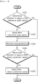
- FIG. 6 is a diagram showing an embodiment of the proposed method of performing intra-prediction using an adaptive filter.
- an encoder determines whether to apply the adaptive filter to a reference pixel value.
- the encoder may determine whether to apply the adaptive filter on the basis of information about a surrounding block or according to a Rate-Distortion Optimization (RDO) method.
- RDO Rate-Distortion Optimization
- a prediction mode of a current block may be determined based on prediction mode information (i.e., a Most Probable Mode (MPM) about the surrounding block, and whether to apply the adaptive filter to the reference pixel value may be determined according to the determined prediction mode of the current block. For example, assuming that a current block is 'C' , an upper block is 'A' , and a left block is 'B' , when a prediction mode of the current block is the same as a prediction mode of the upper block 'A' , the prediction mode of the upper block 'A' may be determined as the prediction mode of the current block.
- prediction mode information i.e., a Most Probable Mode (MPM) about the surrounding block
- MPM Most Probable Mode
- the prediction mode of the left block 'B' may be determined as the prediction mode of the current block.
- the prediction mode of the current block is a prediction mode other than the prediction mode of the upper block 'A' or the prediction mode of the left block 'B'
- a relevant prediction mode is encoded and transmitted. Whether to apply the adaptive filter to the reference pixel value may be determined according to the prediction mode of the current block determined as described above. Even when the current block, the upper block, and the left block have different sizes, the prediction mode of a current block may be determined based on the prediction mode of a surrounding block.
- whether to apply the adaptive filter may be determined on the basis of a shift in the surrounding reference pixel value. For example, assuming that a reference pixel value to which the filter will be applied is p[n], a difference between p[n-1] and p[n+1] (i.e., surrounding reference pixel values) may be calculated, and whether to apply the filter may be determined by comparing the difference with a specific threshold.
- whether to apply the filter to the reference pixel value may be determined based on the size of a current block other than a prediction mode of the current block.
- whether to apply the filter is previously designated based on the prediction mode of the current block and the size of the current block, and whether to apply the filter is adaptively determined according to the relevant prediction mode or the relevant size.
- Table 1 indicates whether to apply the filter according to the prediction mode of a current block and the size of the current block.
- '0' indicates that the filter is not applied
- '1' indicates that the filter is applied. For example, when the size of the current block is 4 ⁇ 4, if the prediction mode of the current block is 1, the filter may not be applied. If the prediction mode of the current block is 3, the filter may be applied.
- whether to apply the filter to the reference pixel value may be determined according to whether surrounding blocks have been subjected to intra-frame encoding or inter-frame encoding. For example, when constrained intra-prediction is performed, a value subjected to the inter-frame encoding is filled with the value of a surrounding block subjected to intra-frame encoding when the surrounding block is subjected to the inter-frame encoding.
- filter may not be applied.
- the encoder applies the filter to the reference pixel value at step S202.
- the applied filter may be a common filter.
- the 3-tap filter of Equation 1 may be used, or a 2-tap filter may be used.
- various filter coefficients such as (1/8, 7/8), (2/8, 6/8), and (3/8, 5/8), may be used.
- the reference pixel value to which the filter has been applied may be used when the filter is applied to other reference pixel values.
- the filter may be applied to all reference pixel values or only some of the reference pixel values.
- the encoder performs intra-prediction on the basis of the reference pixel value to which the filter has been applied or to which the filter has not been applied.
- the encoder determines whether to apply the filter to a prediction value for each prediction mode, predicted by performing the intra-prediction, in order to encode a current block.
- each prediction mode may be each of the 9 prediction modes in the 4 ⁇ 4 luma prediction mode.
- whether to apply the filter may be determined based on information about a surrounding block or according to the RDO method.
- a prediction mode of the current block may be determined based on prediction mode information (MPM) about the surrounding block, and whether to apply the filter to the prediction value may be determined based on the determined prediction mode of the current block. For example, assuming that a current block is 'C' , an upper block is 'A' , and a left block is 'B' , when a prediction mode of the current block is the same as a prediction mode of the upper block 'A' , the prediction mode of the upper block 'A' may be determined as the prediction mode of the current block.
- MPM prediction mode information
- the prediction mode of the left block 'B' may be determined as the prediction mode of the current block.
- the prediction mode of the current block is a prediction mode other than the prediction mode of the upper block 'A' or the prediction mode of the left block 'B'
- a relevant prediction mode is encoded and transmitted.
- the prediction mode of the current block is a specific prediction mode (DC or planar)
- a difference between a reference pixel value and a prediction value may be relatively greater than that of other prediction modes.
- a difference between a reference pixel value and a prediction value in the planar prediction mode may be relatively greater than that of other prediction modes.
- the prediction value in the planar prediction mode may be calculated by averaging a first prediction value, obtained by horizontally performing linear interpolation for each row, and a second prediction value obtained by vertically performing linear interpolation for each column.
- a right value is the same as a value placed at a right upward position (i.e., D in FIG. 3 ), from among the reference pixel values.
- a downward value is the same as a value placed at a left downward position (i.e., L in FIG. 3 ), from among the reference pixel values. Since the prediction value is not directly obtained from the reference pixel value, a difference between the reference pixel value and the prediction value may be relatively great.
- intra-prediction efficiency may be increased by applying the filter to the prediction value.
- Whether to apply the filter to the prediction value may be determined according to the prediction mode of the current block determined as described above. Even when a current block, an upper block, and a left block have different sizes, a prediction mode of the current block may be determined according to the prediction mode of a surrounding block.
- whether to apply the filter to the prediction value may be determined according to the size of a current block besides the prediction mode of a current block.
- whether to apply the filter according to the prediction mode of the current block and the size of the current block is previously designated, and whether to apply the filter is adaptively determined according to the relevant prediction mode or the relevant size.
- whether to apply the filter to the prediction value may be determined according to whether surrounding blocks have been subjected to intra-frame encoding or inter-frame encoding.
- the encoder applies the filter to the prediction value at step S205. Accordingly, the prediction of the current block is completed, and the encoder calculates a residual signal and performs entropy coding.
- FIG. 7 is a diagram showing an example in which the filter is applied to the prediction value according to the proposed method of performing intra-prediction using the adaptive filter.
- the filter may be applied to only the prediction values of pixels adjacent to the boundary with surrounding restored reference pixel values. For example, filtering may be performed for prediction values corresponding to a1 ⁇ a8, and b1, c1, d1, e1, f1, g1, and h1 corresponding to the pixels of one line which is placed at the boundary in FIG. 7 .
- filtering may be performed for prediction values corresponding to a1 ⁇ a8, b1 ⁇ b8, and c1 ⁇ c2, d1 ⁇ d2, e1 ⁇ e2, f1 ⁇ f2, g1 ⁇ g2, and h1 ⁇ h2 corresponding to the pixels of two lines which are placed at the boundary in FIG. 7 .
- the applied filter may be a common filter.
- the 3-tap filter of Equation 1 may be used or a 2-tap filter may be used.
- various filter coefficients such as (1/8, 7/8), (2/8, 6/8), and (3/8, 5/8), may be used.
- any one of the 2-tap filter and the 3-tap filter may be selected and sued according to the positions of pixels.
- the filter may be applied to prediction values which correspond to a1 ⁇ a8 having a relatively great difference between the reference pixel value and the prediction value. Furthermore, in the case where the prediction mode of a current block is a prediction mode using the reference pixel values corresponding to Q ⁇ X as in the mode 1 or the mode 8, the filter may be applied to prediction values which correspond to a1, b1, c1, d1, e1, f1, g1, and h1 having a relatively great difference between the reference pixel value and the prediction value
- Equation 2 is an example of Equation, indicating the filter applied to prediction values when the 2-tap filter or the 3-tap filter is selected and used according to the positions of pixels.
- f a 1 2 ⁇ A + 4 ⁇ a 1 + 2 ⁇ Q / 8
- f b 1 2 ⁇ B + 6 ⁇ b 1 / 8
- f c 1 2 ⁇ C + 6 ⁇ c 1 / 8
- f a 2 2 ⁇ R + 6 ⁇ a 2 / 8
- f a 3 2 ⁇ S + 6 ⁇ a 3 / 8 ...
- Equation 2 f[a1] is a value in which the filter is applied to the prediction value a1, and A and Q indicate the reference pixel values. From Equation 2, it can be seen that the 3-tap filter is applied to the prediction value of a pixel where the prediction value a1 is placed, and the 2-tap filter is applied to the prediction values of remaining pixels.
- Equation 3 is another example of Equation, indicating the filter applied to prediction values when the filter is applied to the prediction values according to the proposed method of performing intra-prediction using the adaptive filter.
- Vertical low ⁇ pass filter v a 1 A + 2 ⁇ a 1 + a 2 / 4
- v a 2 v a 1 + 2 ⁇ a 2 + a 3 / 4
- v a 8 v a 7 + 3 ⁇ a 8 / 4
- v b 1 B + 2 ⁇ b 1 + b 2 / 4 ... 2.
- the filter may be used when the adaptive filter is applied according to the method using information about surrounding blocks or the RDO method for each of the prediction modes.
- a low-pass filter having filter coefficients (1, 2, 1) is sequentially applied to two vertical and horizontal directions. First, the filter is applied to the vertical direction, and the filter is applied to the horizontal direction based on a prediction value to which the filter has been applied. The prediction value to which the filter has been applied may be used when the filter is applied to other prediction values.
- the method of performing intra-prediction described with reference to FIG. 6 may be repeatedly performed.
- FIG. 8 is a block diagram of an encoder and a decoder in which the embodiments of the present invention are implemented.
- the encoder 800 includes a processor 810 and memory 820.
- the processor 810 implements the proposed functions, processes, and/or methods.
- the processor 810 is configured to determine whether to apply a first filter to reference pixel values based on information about surrounding blocks of a current block, apply the first filter to the reference pixel values if, as a result of the determination, the first filter is determined to be applied, perform intra-prediction for the current block on the basis of the reference pixel values, determine whether to apply a second filter to a prediction value for each prediction mode of the current block which has been predicted by performing the intra-prediction based on the information about surrounding blocks, and apply the second filter to the prediction value for each prediction mode of the current block if, as a result of the determination, the second filter is determined to be applied.
- the memory 820 is connected to the processor 810 and is configured to store various pieces of information for driving the processor 810.
- the decoder 900 includes a processor 910 and memory 920.
- the processor 910 implements the proposed functions, processes, and/or methods.
- the processor 910 is configured to determine whether to apply a first filter to reference pixel values based on information about surrounding blocks of a current block, apply the first filter to the reference pixel values if, as a result of the determination, the first filter is determined to be applied, perform intra-prediction for the current block on the basis of the reference pixel values, determine whether to apply a second filter to a prediction value for each prediction mode of the current block which has been predicted by performing the intra-prediction based on the information about surrounding blocks, and apply the second filter to the prediction value for each prediction mode of the current block if, as a result of the determination, the second filter is determined to be applied.
- the memory 920 is connected to the processor 910 and is configured to store various pieces of information for driving the processor 910.
- the processor 810, 910 may include Application-Specific Integrated Circuits (ASICs), other chipsets, logic circuits, and/or data processors.
- the memory 820, 920 may include Read-Only Memory (ROM), Random Access Memory (RAM), flash memory, a memory card, a storage medium, and/or other storage devices.
- ROM Read-Only Memory
- RAM Random Access Memory
- flash memory a memory card
- storage medium a storage medium
- the above schemes may be implemented using a module (or a process or function) for performing the above functions.
- the module may be stored in the memory 820, 920 and may be executed by the processor 810, 910.
- the memory 820, 920 may be internal or external to the processor 810, 910 and may be coupled to the processor 810, 910 using a variety of well-known means.
- a method of performing intra-prediction comprising:
- the first filter is at least any one of a 3-tap filter and a 2-tap filter.
- the second filter is at least any one of a 3-tap filter and a 2-tap filter.
- An encoder comprising:
- a decoder comprising:
Abstract
Description
- The present invention relates to video coding, and more particularly, to a method and apparatus for performing intra-prediction by applying an adaptive filter to the surrounding pixel values of a block to be predicted or the predicted pixel values of a current block.
- With the recent advent of digital TV, etc., technology in the broadcasting TV and home entertainment fields are abruptly being developed. Technology of the fields is being commercialized by the standardization of video compression technology. For video compression, an ITU-T (International Telecommunications Union-Telecommunication) H. 263 standard is being widely used. MPEG-4 which is the next standard of MPEG (Motion Picture Experts Group) is being used for Internet-based video applications.
- After the H. 263 standard was completed, ITU-T VCEG (Video Coding Experts Group) has devoted itself to achieve a short-term target for adding additional characteristics to the H. 263 standard and a long-term target for developing a new standard for visual communication of a low bit rate. In the year of 2001, JVT (Joint Video Team) consisting of the experts of MPEG and VCEG was constructed, and the JVT has performed a standardization task of ITU-T H. 264/MPEG-4 part 10 which is a new standard for the coding of video. The H. 264 standard may also be called AVC (Advanced Video Coding). The technological target of the H. 264/AVC is for the significant improvement of coding efficiency, coding technology robust to loss and error, network-friendly coding technology, low latency capability, accurate match decoding, and so on.
- Most of surrounding pixels within video have similar values. The same principle applies to 4×4 blocks or 16×16 blocks which are a minimum block size of the H. 264/AVC standard. Prediction for the video may be performed using the likeness between inter-block values as described above, and a difference between the video and an original video can be encoded. This is called intra-prediction. The efficiency of video coding can be increased by intra-prediction.
- Furthermore, in performs intra-prediction, a filter may be applied before the intra-prediction is performed. In typical cases, when intra-prediction is performed in the H. 264/AVC standard, a filter is applied to reference pixel values, and the values to which the filter has been applied are used for the intra-prediction. However, the performance of video coding may be increased when the intra-prediction is performed without applying the filter rather than when the intra-prediction is performed after the filter is applied, according to circumstances.
- Accordingly, there may be proposed a method of determining whether to apply a filter when performing intra-prediction.
- An object of the present invention is to provide a method and apparatus for performing intra-prediction by applying an adaptive filter to surrounding pixel values of a block to be predicted or the predicted pixel values of a current block in video encoding. More particularly, after an adaptive filter (i.e., a pre-filter) is applied to reference pixel values of a current block for performing intra-prediction, prediction is performed. Furthermore, a residual signal is calculated after applying an adaptive filter (i.e., a post-filter) to the pixel values of a predicted current block.
- In an aspect, there is provided a method of performing intra-prediction. The method of performing intra-prediction includes determining whether to apply a first filter to a reference pixel value based on information about surrounding blocks of a current block, if, as a result of the determination, the first filter is determined to be applied, applying the first filter to the reference pixel values, performing intra-prediction for the current block based on the reference pixel value, determining whether to apply a second filter to a prediction value for each prediction mode of the current block, predicted by performing the intra-prediction based on the information about the surrounding blocks, and if, as a result of the determination, the second filter is determined to be applied, applying the second filter to the prediction values for each prediction mode.
- Whether to apply the first filter may be determined based on the prediction mode of the current block determined based on the information about the surrounding blocks.
- Whether to apply the first filter may be determined based on the size of the current block.
- Whether to apply the first filter may be previously designated based on the prediction mode of the current block and the size of the current block.
- Whether to apply the first filter may be determined based on whether the surrounding blocks have been subjected to intra-frame coding or inter-frame coding.
- The first filter may be at least any one of a 3-tap filter and a 2-tap filter.
- Whether to apply the second filter may be determined based on the prediction mode of the current block determined based on the information about the surrounding blocks.
- Whether to apply the second filter may be determined based on the size of the current block.
- Whether to apply the second filter may be determined based on whether the surrounding blocks have been subjected to intra-frame encoding or inter-frame encoding.
- The second filter may be applied to prediction values of pixels adjacent to the boundary of the reference pixel value.
- The second filter may be at least any one of a 3-tap filter and a 2-tap filter.
- In another aspect, there is a provided encoder. The encoder includes a processor and memory connected to the processor and configured to store pieces of information for driving the processor. The processor is configured to determine whether to apply a first filter to a reference pixel value based on information about surrounding blocks of a current block, if, as a result of the determination, the first filter is determined to be applied, apply the first filter to the reference pixel value, perform intra-prediction for the current block based on the reference pixel value, determine whether to apply a second filter to a prediction value for each prediction mode of the current block, predicted by performing the intra-prediction based on the information about the surrounding blocks, and if, as a result of the determination, the second filter is determined to be applied, apply the second filter to the prediction value for each prediction mode.
- In yet another aspect, there is a provided decoder. The decoder includes a processor and memory connected to the processor and configured to store pieces of information for driving the processor. The processor is configured to determine whether to apply a first filter to a reference pixel value based on information about surrounding blocks of a current block, if, as a result of the determination, the first filter is determined to be applied, apply the first filter to the reference pixel value, perform intra-prediction for the current block based on the reference pixel value, determine whether to apply a second filter to a prediction value for each prediction mode of the current block, predicted by performing the intra-prediction based on the information about the surrounding blocks, and if, as a result of the determination, the second filter is determined to be applied, apply the second filter to the prediction value for each prediction mode.
- The performance of coding is improved by effectively predicting a luminance or chrominance signal block to be encoded.
-
-
FIG. 1 is a block diagram of an encoder according to the H. 264/AVC (Advanced Video Coding) standard. -
FIG. 2 is a block diagram of a decoder according to the H. 264/AVC standard. -
FIG. 3 is a diagram showing an example of labeled prediction samples in a 4×4 luma prediction mode. -
FIG. 4 is a diagram showing 9 kinds of prediction modes within the 4×4 luma prediction mode. -
FIG. 5 is a diagram showing an example of a method of applying a filter before intra-prediction is performed. -
FIG. 6 is a diagram showing an embodiment of a proposed method of performing intra-prediction using an adaptive filter. -
FIG. 7 is a diagram showing an example in which a filter is applied to a prediction value according to the proposed method of performing intra-prediction using the adaptive filter. -
FIG. 8 is a block diagram of an encoder and a decoder in which the embodiments of the present invention are implemented. - Hereinafter, embodiments of the present invention are described in detail with reference to the accompanying drawings in order for those skilled in the art to be able to readily implement the present invention. However, the present invention may be implemented in various different ways and are not limited to the following embodiments. In order to clarify a description of the present invention, parts not related to the description are omitted, and similar reference numbers are used throughout the drawings to refer to similar parts. Furthermore, a description of parts which can be readily understood by those skilled in the art is omitted.
- Furthermore, when it is said that any part "includes (or comprises)" any element, it means that the corresponding part may further include other elements unless otherwise described without excluding the elements.
-
FIG. 1 is a block diagram of an encoder according to the H. 264/AVC (Advanced Video Coding) standard. - Referring to
FIG. 1 , the encoder includes two kinds of data flow paths. One of them is a forward path, and the other thereof is a reconstruction path. - First, the forward path is described. Encoding is performed for an input frame Fn for each macroblock. The macroblock has the size of 16×16 pixels in an original video. Intra-prediction or inter-prediction is performed for each input frame. In the intra-prediction, prediction is performed using a likeness between inter-block values within the frame, and a difference between the original video and a relevant video is encoded. In the inter-prediction, prediction is performed using a likeness between inter-block values between frames, and a difference between the original video and a relevant video is encoded. At the time of the intra-prediction or the inter-prediction, P (i.e., a prediction macroblock) is formed on the basis of the reconstructed frame. At the time of the intra-prediction, the prediction macroblock P may be formed from samples within a previously encoded current frame, a decoded current frame, or a reconstructed current frame uFn'. When the prediction macroblock P is formed from the reconstructed current frame, unfiltered samples may be used. At the time of the inter-prediction, the prediction macroblock P may be formed from one or more reference frames through motion compensation or motion prediction. In
FIG. 1 , it is assumed that the reference frame is a previously encoded frame Fn-1'. However, the present invention is not limited thereto, and each prediction macroblock may be formed from a previous 1 frame or previous 2 frames already encoded or reconstructed, or a subsequent frame or subsequent 2 frames. - P is subtracted from the current macroblock in order to generate a residual or different macroblock Dn. The macroblock Dn is transformed (T) using a block transform and quantized (Q), thus generating X. X is a set of encoded coefficients. The encoded coefficients are reordered and then subjected to entropy coding. The entropy-coded coefficients form a compressed bit stream, along with information necessary to decode the macroblock. The compressed bit stream is sent to a Network Abstraction Layer (NAL) for transmission or storage.
- The reconstruction path is described below. The quantized macroblock coefficients X are decoded in order to generate a reconstructed frame which is used to encode other macroblocks. X are inverse quantized (Q-1) and then inverse transformed (T-1), thus generating a macroblock Dn' . The difference macroblock Dn' generated in the reconstruction path is not the same as the difference macroblock Dn generated in the forward path. Loss is generated because of the quantization, and thus the macroblock Dn' may have a distorted form of Dn. The prediction macroblock P is added to the macroblock Dn', and a reconstruction macroblock uFn' is generated. The reconstruction macroblock uFn' may also have a distorted form of the original macroblock Fn. In order to reduce blocking distortion for the reconstruction macroblock uFn', a filter may be applied. A reconstructed frame may be formed from a plurality of reconstruction macroblocks to which the filter has been applied.
-
FIG. 2 is a block diagram of a decoder according to the H. 264/AVC standard. - Referring to
FIG. 2 , the decoder receives a compressed bit stream from an NAL. The received data is subjected to entropy decoding in order to generate a set of quantized coefficients X and then reordered. Inverse quantization and inverse transform are performed for the quantized coefficients X, thereby generating Dn'. The decoder generates the same prediction macroblock P as a prediction macroblock, generated at an encoder, using header information decoded from the bit stream. uFn' is generated by adding Dn' to P, and uFn' may experience a filter, thereby generating a decoded macroblock Fn'. - Intra-prediction is described below.
- When the intra-prediction is performed for a block (or a macroblock), a prediction block (or a macroblock) P may be formed on the basis of encoded blocks (or macroblocks) or reconstructed blocks (or macroblocks). P is subtracted from an original video, and a difference from which P has been subtracted is encoded and then transmitted. The intra-prediction may be performed according to a luma prediction mode or a chroma prediction mode. In the luma prediction mode, the intra-prediction may be performed in the unit of a 4×4 sub-block size or a 16×16 macroblock size. A total of 9 additional prediction modes exist in the 4×4 luma prediction mode, and a total of 4 additional prediction modes exist in the 16×16 luma prediction mode. The unit in which the intra-prediction is performed is not limited to the sub-block or the macroblock, but may be performed using various sizes as the unit. The unit of a pixel in which the intra-prediction is performed may be called a Coding Unit (CU) or a Prediction Unit (PU). The size of the CU or the PU may be the same as the size of a sub-block or a macroblock as described above.
-
FIG. 3 is a diagram showing an example of labeled prediction samples in the 4×4 luma prediction mode. Referring toFIG. 3 , a prediction block P is A to H or I to L and is calculated on the basis of labeled samples. -
FIG. 4 is a diagram showing 9 kinds of prediction modes within the 4×4 luma prediction mode. - An encoder may select any one of the 9 prediction modes for each block in order to minimize a difference between a prediction block P and a block to be encoded. The 9 prediction modes are as follows.
- 1) mode 0 (vertical): A to D which are upper samples of the prediction block are vertically extrapolated.
- 2) mode 1 (horizontal): I to L which are left samples of the prediction block are horizontally extrapolated.
- 3) mode 2 (DC); all the samples A to D and I to L within the prediction block P are predicted by average.
- 4) mode 3 (diagonal down-left): samples within the prediction block P are interpolated at an angle of 45° between a left down and a right up.
- 5) mode 4 (diagonal down-right): samples within the prediction block P are extrapolated right downward at an angle of 45°.
- 6) mode 5 (vertical-right): samples within the prediction block P are extrapolated or interpolated to the right at an angle of about 26.6° in a vertical axis.
- 7) mode 6 (horizontal-down): samples within the prediction block P are extrapolated downward at an angle of about 26.6° in a horizontal axis.
- 8) mode 7 (vertical-left): samples within the prediction block P are extrapolated to the left at an angle of about 26.6° in the vertical axis.
- 9) mode 8 (horizontal-up): samples within the prediction block P are interpolated upward at an angle of about 26.6° in the horizontal axis.
- In
FIG. 4 , the arrow indicates a direction in which prediction is performed within each mode. Meanwhile, in relation to themode 3 to themode 8, the samples within the prediction block P are formed from a weighted average of the prediction samples A to H or I to L. For example, in themode 4, a sample d placed on the right upper side of the prediction block P may be predicted as round (B/4+C/2+D/4). The encoder calculates the Sum of Absolute Errors (SAE) for a prediction block generated by each of the prediction modes and performs intra-prediction based on the prediction mode having the smallest SAE. -
FIG. 5 is a diagram showing an example of a method of applying a filter before intra-prediction is performed. - In general, a filter is applied to samples used in the H. 264/AVC standard, and intra-prediction is then performed. The samples may also be called reference pixel values. In the example of
FIG. 5 , it is assumed that a filter is a low-pass filter and is applied to only an 8×8 block. -
Equation 1 is an example of Equation showing a 3-tap filter applied to a reference pixel value.
- h[Z] indicates a value calculated by applying the filter to Z. Referring to
Equation 1, filtering for the reference pixel value is performed by applying filter coefficients (1,2,1), and intra-prediction according to the 9 prediction modes is performed on the basis of reference pixel values h[A]∼h[Z] that has been filtered. Like in the encoding process, the filter may be applied even in a decoding process. - In performing filtering before intra-prediction is performed, the performance of encoding may be improved when the filtering is not performed. Accordingly, a method of performing intra-prediction by adaptively applying the filter may be proposed.
-
FIG. 6 is a diagram showing an embodiment of the proposed method of performing intra-prediction using an adaptive filter. - Referring to
FIG. 6 , at step S201, an encoder determines whether to apply the adaptive filter to a reference pixel value. When determining whether to apply the adaptive filter, the encoder may determine whether to apply the adaptive filter on the basis of information about a surrounding block or according to a Rate-Distortion Optimization (RDO) method. - When determining whether to apply the adaptive filter to the reference pixel value based on the information about a surrounding block, a prediction mode of a current block may be determined based on prediction mode information (i.e., a Most Probable Mode (MPM) about the surrounding block, and whether to apply the adaptive filter to the reference pixel value may be determined according to the determined prediction mode of the current block. For example, assuming that a current block is 'C' , an upper block is 'A' , and a left block is 'B' , when a prediction mode of the current block is the same as a prediction mode of the upper block 'A' , the prediction mode of the upper block 'A' may be determined as the prediction mode of the current block. When the prediction mode of the current block is the same as a prediction mode of the left block 'B' , the prediction mode of the left block 'B' may be determined as the prediction mode of the current block. Alternatively, when the prediction mode of the current block is a prediction mode other than the prediction mode of the upper block 'A' or the prediction mode of the left block 'B' , a relevant prediction mode is encoded and transmitted. Whether to apply the adaptive filter to the reference pixel value may be determined according to the prediction mode of the current block determined as described above. Even when the current block, the upper block, and the left block have different sizes, the prediction mode of a current block may be determined based on the prediction mode of a surrounding block.
- Alternatively, in determining whether to apply the adaptive filter to the reference pixel value based on the information about a surrounding block, whether to apply the adaptive filter may be determined on the basis of a shift in the surrounding reference pixel value. For example, assuming that a reference pixel value to which the filter will be applied is p[n], a difference between p[n-1] and p[n+1] (i.e., surrounding reference pixel values) may be calculated, and whether to apply the filter may be determined by comparing the difference with a specific threshold.
- Alternatively, whether to apply the filter to the reference pixel value may be determined based on the size of a current block other than a prediction mode of the current block. Here, whether to apply the filter is previously designated based on the prediction mode of the current block and the size of the current block, and whether to apply the filter is adaptively determined according to the relevant prediction mode or the relevant size.
- Table 1 indicates whether to apply the filter according to the prediction mode of a current block and the size of the current block.
[Table 1] PREDICTION MODE OF CURRENT BLOCK SIZE OF CURRENT BLOCK 4×4 8×8 16×16 32×32 0 0 0 0 0 1 0 0 0 0 2 0 0 0 0 3 1 1 1 1 4 0 1 1 1 ··· ··· ··· ··· ··· - Referring to Table 1, '0' indicates that the filter is not applied, and '1' indicates that the filter is applied. For example, when the size of the current block is 4×4, if the prediction mode of the current block is 1, the filter may not be applied. If the prediction mode of the current block is 3, the filter may be applied.
- Furthermore, whether to apply the filter to the reference pixel value may be determined according to whether surrounding blocks have been subjected to intra-frame encoding or inter-frame encoding. For example, when constrained intra-prediction is performed, a value subjected to the inter-frame encoding is filled with the value of a surrounding block subjected to intra-frame encoding when the surrounding block is subjected to the inter-frame encoding. Here, filter may not be applied.
- If, as a result of the determination, the filter is determined to be applied to the reference pixel value, the encoder applies the filter to the reference pixel value at step S202. The applied filter may be a common filter. For example, the 3-tap filter of
Equation 1 may be used, or a 2-tap filter may be used. When the 2-tap filter is used, various filter coefficients, such as (1/8, 7/8), (2/8, 6/8), and (3/8, 5/8), may be used. The reference pixel value to which the filter has been applied may be used when the filter is applied to other reference pixel values. Furthermore, when the filter is applied to the reference pixel value, the filter may be applied to all reference pixel values or only some of the reference pixel values. - At step S203, the encoder performs intra-prediction on the basis of the reference pixel value to which the filter has been applied or to which the filter has not been applied.
- At step S204, the encoder determines whether to apply the filter to a prediction value for each prediction mode, predicted by performing the intra-prediction, in order to encode a current block. Here, each prediction mode may be each of the 9 prediction modes in the 4×4 luma prediction mode. When determining whether to apply the filter to a prediction value for each prediction mode, whether to apply the filter may be determined based on information about a surrounding block or according to the RDO method.
- When determining whether to apply the filter to the prediction value based on the information about a surrounding block, a prediction mode of the current block may be determined based on prediction mode information (MPM) about the surrounding block, and whether to apply the filter to the prediction value may be determined based on the determined prediction mode of the current block. For example, assuming that a current block is 'C' , an upper block is 'A' , and a left block is 'B' , when a prediction mode of the current block is the same as a prediction mode of the upper block 'A' , the prediction mode of the upper block 'A' may be determined as the prediction mode of the current block. When the prediction mode of the current block is same as a prediction mode of the left block 'B' , the prediction mode of the left block 'B' may be determined as the prediction mode of the current block. Alternatively, when the prediction mode of the current block is a prediction mode other than the prediction mode of the upper block 'A' or the prediction mode of the left block 'B' , a relevant prediction mode is encoded and transmitted. Here, when the prediction mode of the current block is a specific prediction mode (DC or planar), a difference between a reference pixel value and a prediction value may be relatively greater than that of other prediction modes. For example, a difference between a reference pixel value and a prediction value in the planar prediction mode may be relatively greater than that of other prediction modes. The prediction value in the planar prediction mode may be calculated by averaging a first prediction value, obtained by horizontally performing linear interpolation for each row, and a second prediction value obtained by vertically performing linear interpolation for each column. When the linear interpolation is horizontally performed, a right value is the same as a value placed at a right upward position (i.e., D in
FIG. 3 ), from among the reference pixel values. When the linear interpolation is vertically performed, a downward value is the same as a value placed at a left downward position (i.e., L inFIG. 3 ), from among the reference pixel values. Since the prediction value is not directly obtained from the reference pixel value, a difference between the reference pixel value and the prediction value may be relatively great. In this case, intra-prediction efficiency may be increased by applying the filter to the prediction value. Whether to apply the filter to the prediction value may be determined according to the prediction mode of the current block determined as described above. Even when a current block, an upper block, and a left block have different sizes, a prediction mode of the current block may be determined according to the prediction mode of a surrounding block. - Alternatively, whether to apply the filter to the prediction value may be determined according to the size of a current block besides the prediction mode of a current block. Here, whether to apply the filter according to the prediction mode of the current block and the size of the current block is previously designated, and whether to apply the filter is adaptively determined according to the relevant prediction mode or the relevant size. Alternatively, whether to apply the filter to the prediction value may be determined according to whether surrounding blocks have been subjected to intra-frame encoding or inter-frame encoding.
- If, as a result of the determination, the filter is determined to have been applied to the prediction value, the encoder applies the filter to the prediction value at step S205. Accordingly, the prediction of the current block is completed, and the encoder calculates a residual signal and performs entropy coding.
-
FIG. 7 is a diagram showing an example in which the filter is applied to the prediction value according to the proposed method of performing intra-prediction using the adaptive filter. - Referring to
FIG. 7 , in the case where the prediction mode of a current block is a non-directional mode, a difference between a reference pixel value and a prediction value may become relatively greater than that of other prediction modes. Accordingly, the filter may be applied to only the prediction values of pixels adjacent to the boundary with surrounding restored reference pixel values. For example, filtering may be performed for prediction values corresponding to a1∼a8, and b1, c1, d1, e1, f1, g1, and h1 corresponding to the pixels of one line which is placed at the boundary inFIG. 7 . Alternatively, filtering may be performed for prediction values corresponding to a1∼a8, b1∼b8, and c1∼c2, d1∼d2, e1∼e2, f1∼f2, g1∼g2, and h1∼h2 corresponding to the pixels of two lines which are placed at the boundary inFIG. 7 . Here, the applied filter may be a common filter. For example, the 3-tap filter ofEquation 1 may be used or a 2-tap filter may be used. When the 2-tap filter is used, various filter coefficients, such as (1/8, 7/8), (2/8, 6/8), and (3/8, 5/8), may be used. Alternatively, any one of the 2-tap filter and the 3-tap filter may be selected and sued according to the positions of pixels. - In the case where the prediction mode of a current block is a prediction mode using the reference pixel values corresponding to A∼P as in the
mode 0, themode 3, or themode 7 in this way, the filter may be applied to prediction values which correspond to a1∼a8 having a relatively great difference between the reference pixel value and the prediction value. Furthermore, in the case where the prediction mode of a current block is a prediction mode using the reference pixel values corresponding to Q∼X as in themode 1 or themode 8, the filter may be applied to prediction values which correspond to a1, b1, c1, d1, e1, f1, g1, and h1 having a relatively great difference between the reference pixel value and the prediction value -
Equation 2 is an example of Equation, indicating the filter applied to prediction values when the 2-tap filter or the 3-tap filter is selected and used according to the positions of pixels.
- In
Equation 2, f[a1] is a value in which the filter is applied to the prediction value a1, and A and Q indicate the reference pixel values. FromEquation 2, it can be seen that the 3-tap filter is applied to the prediction value of a pixel where the prediction value a1 is placed, and the 2-tap filter is applied to the prediction values of remaining pixels. -
Equation 3 is another example of Equation, indicating the filter applied to prediction values when the filter is applied to the prediction values according to the proposed method of performing intra-prediction using the adaptive filter.
- In
Equation 3, the filter may be used when the adaptive filter is applied according to the method using information about surrounding blocks or the RDO method for each of the prediction modes. Referring toEquation 3, a low-pass filter having filter coefficients (1, 2, 1) is sequentially applied to two vertical and horizontal directions. First, the filter is applied to the vertical direction, and the filter is applied to the horizontal direction based on a prediction value to which the filter has been applied. The prediction value to which the filter has been applied may be used when the filter is applied to other prediction values. - Meanwhile, when the RDO method is used, the method of performing intra-prediction described with reference to
FIG. 6 may be repeatedly performed. -
FIG. 8 is a block diagram of an encoder and a decoder in which the embodiments of the present invention are implemented. - The
encoder 800 includes aprocessor 810 andmemory 820. Theprocessor 810 implements the proposed functions, processes, and/or methods. Theprocessor 810 is configured to determine whether to apply a first filter to reference pixel values based on information about surrounding blocks of a current block, apply the first filter to the reference pixel values if, as a result of the determination, the first filter is determined to be applied, perform intra-prediction for the current block on the basis of the reference pixel values, determine whether to apply a second filter to a prediction value for each prediction mode of the current block which has been predicted by performing the intra-prediction based on the information about surrounding blocks, and apply the second filter to the prediction value for each prediction mode of the current block if, as a result of the determination, the second filter is determined to be applied. Thememory 820 is connected to theprocessor 810 and is configured to store various pieces of information for driving theprocessor 810. - The
decoder 900 includes aprocessor 910 andmemory 920. Theprocessor 910 implements the proposed functions, processes, and/or methods. Theprocessor 910 is configured to determine whether to apply a first filter to reference pixel values based on information about surrounding blocks of a current block, apply the first filter to the reference pixel values if, as a result of the determination, the first filter is determined to be applied, perform intra-prediction for the current block on the basis of the reference pixel values, determine whether to apply a second filter to a prediction value for each prediction mode of the current block which has been predicted by performing the intra-prediction based on the information about surrounding blocks, and apply the second filter to the prediction value for each prediction mode of the current block if, as a result of the determination, the second filter is determined to be applied. Thememory 920 is connected to theprocessor 910 and is configured to store various pieces of information for driving theprocessor 910. - The
processor memory memory processor memory processor processor - In the above-described exemplary systems, although the methods have been described on the basis of the flowcharts using a series of steps or blocks, the present invention is not limited to the sequence of the steps, and some of the steps may be performed at different sequences from the remaining steps or may be performed simultaneously with the remaining steps. Furthermore, those skilled in the art will understand that the steps shown in the flowcharts are not exclusive and other steps may be included or one or more steps of the flowcharts may be deleted without affecting the scope of the present invention.
- The above-described embodiments include various aspects of illustrations. Although all kinds of possible combinations for representing the various aspects may not be described, a person having ordinary skill in the art will understand that other possible combinations are possible. Accordingly, the present invention may be said to include all other replacements, modifications, and changes belonging to the accompanying claims.
- Although the present invention is defined in the attached claims, it should be understood that the present invention can also (alternatively) be defined in accordance with the following embodiments:
- A method of performing intra-prediction, comprising:
- determining whether to apply a first filter to a reference pixel value based on information about surrounding blocks of a current block;
- if, as a result of the determination, the first filter is determined to be applied, applying the first filter to the reference pixel value;
- performing intra-prediction for the current block based on the reference pixel value;
- determining whether to apply a second filter to a prediction value for each prediction mode of the current block, predicted by performing the intra-prediction based on the information about the surrounding blocks; and
- if, as a result of the determination, the second filter is determined to be applied, applying the second filter to the prediction value for each prediction mode.
- The method of
embodiment 1, wherein whether to apply the first filter is determined based on the prediction mode of the current block determined based on the information about the surrounding blocks. - The method of
embodiment 2, wherein whether to apply the first filter is determined based on a size of the current block. - The method of
embodiment 3, wherein whether to apply the first filter is previously designated based on the prediction mode of the current block and the size of the current block. - The method of
embodiment 1, wherein whether to apply the first filter is determined based on whether the surrounding blocks have been subjected to intra-frame encoding or inter-frame encoding. - The method of
embodiment 1, wherein the first filter is at least any one of a 3-tap filter and a 2-tap filter. - The method of
embodiment 1, wherein whether to apply the second filter is determined based on the prediction mode of the current block determined based on the information about the surrounding blocks. - The method of
embodiment 7, wherein whether to apply the second filter is determined based on a size of the current block. - The method of
embodiment 1, wherein whether to apply the second filter is determined based on whether the surrounding blocks have been subjected to intra-frame encoding or inter-frame encoding. - The method of
embodiment 1, wherein the second filter is applied to prediction values of pixels adjacent to a boundary of the reference pixel value. - The method of
embodiment 1, wherein the second filter is at least any one of a 3-tap filter and a 2-tap filter. - An encoder, comprising:
- a processor; and
- memory connected to the processor and configured to store pieces of information for driving the processor,
- wherein the processor is configured to:
- determine whether to apply a first filter to a reference pixel value based on information about surrounding blocks of a current block;
- if, as a result of the determination, the first filter is determined to be applied, apply the first filter to the reference pixel value;
- perform intra-prediction for the current block based on the reference pixel value;
- determine whether to apply a second filter to a prediction value for each prediction mode of the current block, predicted by performing the intra-prediction based on the information about the surrounding blocks; and
- if, as a result of the determination, the second filter is determined to be applied, apply the second filter to the prediction value for each prediction mode.
- The encoder of embodiment 12, wherein whether to apply the first filter is determined based on the prediction mode of the current block determined based on the information about the surrounding blocks.
- The encoder of embodiment 13, wherein whether to apply the first filter is determined based on a size of the current block.
- The encoder of embodiment 14, wherein whether to apply the first filter is previously designated based on the prediction mode of the current block and the size of the current block.
- A decoder, comprising:
- a processor; and
- memory connected to the processor and configured to store pieces of information for driving the processor,
- wherein the processor is configured to:
- determine whether to apply a first filter to a reference pixel value based on information about surrounding blocks of a current block;
- if, as a result of the determination, the first filter is determined to be applied, apply the first filter to the reference pixel value;
- perform intra-prediction for the current block based on the reference pixel value;
- determine whether to apply a second filter to a prediction value for each prediction mode of the current block, predicted by performing the intra-prediction based on the information about the surrounding blocks; and
- if, as a result of the determination, the second filter is determined to be applied, apply the second filter to the prediction value for each prediction mode.
- The decoder of embodiment 16, wherein whether to apply the first filter is determined based on the prediction mode of the current block determined based on the information about the surrounding blocks.
- The decoder of embodiment 17, wherein whether to apply the first filter is determined based on a size of the current block.
- The decoder of embodiment 18, wherein whether to apply the first filter is previously designated based on the prediction mode of the current block and the size of the current block.
Claims (4)
- A video decoding apparatus adapted to perform steps comprising:determining whether to apply a first filter to a reference pixel value of a current block based on an intra prediction mode of the current block and a size of the current block;when it is determined to apply the first filter to the reference pixel value of the current block, deriving an intra prediction value of the current block using the filtered reference pixel value and the intra prediction mode of the current block; anddetermining whether to apply a second filter to the intra prediction value of the current block based on an intra prediction mode of the current block and a size of the current block, for thereby producing a filtered intra prediction value,wherein the intra prediction mode of the current block is determined based on a Most Probable Mode (MPM),wherein when the intra prediction mode of the current block is a DC mode, the determining whether to apply a second filter to the intra prediction value of the current block is such that a 3-tap filter is applied only to an upper-leftmost pixel of the current block among the prediction pixels of the current block and a 2-tap filter is applied only to remaining uppermost pixels and leftmost pixels except the upper-leftmost pixel among the prediction pixels of the current block.
- The video decoding apparatus of claim 1, wherein the 3-tap filter as the second filter includes a first and second filter coefficients corresponding to the reference pixel value and a third filter coefficient corresponding to the upper-leftmost pixel, wherein the third filter coefficient is 2 times larger than the first filter coefficient, and wherein the first and second coefficient are equal to each other.
- A video encoding apparatus adapted to perform steps comprising:determining whether to apply a first filter to a reference pixel value of a current block based on an intra prediction mode of the current block and a size of the current block;when it is determined to apply the first filter to the reference pixel value of the current block, predicting an intra prediction value of the current block using the filtered reference pixel value and the intra prediction mode of the current block;determining whether to apply a second filter to the intra prediction value of the current block based on the intra prediction mode of the current block and the size of the current block, for thereby producing a filtered intra prediction value; andencoding information including the intra prediction mode of the current block and the size of the current block,wherein the intra prediction mode of the current block is encoded based on a Most Probable Mode (MPM), andwherein when the intra prediction mode of the current block is a DC mode, the determining whether to apply a second filter to the intra prediction value of the current block is such that a 3-tap filter is applied only to an upper-leftmost pixel of the current block among the prediction pixels of the current block and a 2-tap filter is applied only to remaining uppermost pixels and leftmost pixels except the upper-leftmost pixel among the prediction pixels of the current block.
- The video encoding apparatus of claim 3, wherein the 3-tap filter as the second filter includes a first and second filter coefficients corresponding to the reference pixel value and a third filter coefficient corresponding to the upper-leftmost pixel, wherein the third filter coefficient is 2 times larger than the first filter coefficient, and wherein the first and second coefficient are equal to each other.
Applications Claiming Priority (5)
| Application Number | Priority Date | Filing Date | Title |
|---|---|---|---|
| KR20100032778 | 2010-04-09 | ||
| KR1020110026079A KR20110113561A (en) | 2010-04-09 | 2011-03-23 | Method and apparatus for intra prediction encoding and decoding using adaptive filter |
| KR1020110032766A KR101529475B1 (en) | 2010-04-09 | 2011-04-08 | Video decoding apparatus of performing intra prediction using adaptive filter |
| PCT/KR2011/002514 WO2011126349A2 (en) | 2010-04-09 | 2011-04-11 | Method and apparatus for performing intra-prediction using adaptive filter |
| EP11766200.7A EP2557797B1 (en) | 2010-04-09 | 2011-04-11 | Method for performing intra-prediction using adaptive filter |
Related Parent Applications (1)
| Application Number | Title | Priority Date | Filing Date |
|---|---|---|---|
| EP11766200.7A Division EP2557797B1 (en) | 2010-04-09 | 2011-04-11 | Method for performing intra-prediction using adaptive filter |
Publications (1)
| Publication Number | Publication Date |
|---|---|
| EP3823285A1 true EP3823285A1 (en) | 2021-05-19 |
Family
ID=45028890
Family Applications (6)
| Application Number | Title | Priority Date | Filing Date |
|---|---|---|---|
| EP18194215.2A Active EP3448037B1 (en) | 2010-04-09 | 2011-04-11 | Method for performing intra-prediction using adaptive filter |
| EP21150984.9A Pending EP3823285A1 (en) | 2010-04-09 | 2011-04-11 | Apparatus for performing intra-prediction using adaptive filter |
| EP11766200.7A Active EP2557797B1 (en) | 2010-04-09 | 2011-04-11 | Method for performing intra-prediction using adaptive filter |
| EP18194210.3A Revoked EP3448036B1 (en) | 2010-04-09 | 2011-04-11 | Method for performing intra-prediction using adaptive filter |
| EP21150983.1A Pending EP3829178A1 (en) | 2010-04-09 | 2011-04-11 | Apparatus for performing intra-prediction using adaptive filter |
| EP18194204.6A Active EP3448035B1 (en) | 2010-04-09 | 2011-04-11 | Method for performing intra-prediction using adaptive filter |
Family Applications Before (1)
| Application Number | Title | Priority Date | Filing Date |
|---|---|---|---|
| EP18194215.2A Active EP3448037B1 (en) | 2010-04-09 | 2011-04-11 | Method for performing intra-prediction using adaptive filter |
Family Applications After (4)
| Application Number | Title | Priority Date | Filing Date |
|---|---|---|---|
| EP11766200.7A Active EP2557797B1 (en) | 2010-04-09 | 2011-04-11 | Method for performing intra-prediction using adaptive filter |
| EP18194210.3A Revoked EP3448036B1 (en) | 2010-04-09 | 2011-04-11 | Method for performing intra-prediction using adaptive filter |
| EP21150983.1A Pending EP3829178A1 (en) | 2010-04-09 | 2011-04-11 | Apparatus for performing intra-prediction using adaptive filter |
| EP18194204.6A Active EP3448035B1 (en) | 2010-04-09 | 2011-04-11 | Method for performing intra-prediction using adaptive filter |
Country Status (16)
| Country | Link |
|---|---|
| US (16) | US9549204B2 (en) |
| EP (6) | EP3448037B1 (en) |
| JP (15) | JP5583840B2 (en) |
| KR (14) | KR20110113561A (en) |
| CN (5) | CN104994395B (en) |
| CY (2) | CY1123771T1 (en) |
| DK (2) | DK3448035T3 (en) |
| ES (4) | ES2851009T3 (en) |
| HR (2) | HRP20210238T1 (en) |
| HU (2) | HUE052884T2 (en) |
| LT (2) | LT3448035T (en) |
| PL (2) | PL3448035T3 (en) |
| PT (2) | PT3448035T (en) |
| RS (2) | RS61405B1 (en) |
| SI (2) | SI3448035T1 (en) |
| WO (1) | WO2011126349A2 (en) |
Families Citing this family (67)
| Publication number | Priority date | Publication date | Assignee | Title |
|---|---|---|---|---|
| KR101510108B1 (en) | 2009-08-17 | 2015-04-10 | 삼성전자주식회사 | Method and apparatus for encoding video, and method and apparatus for decoding video |
| KR20110113561A (en) | 2010-04-09 | 2011-10-17 | 한국전자통신연구원 | Method and apparatus for intra prediction encoding and decoding using adaptive filter |
| KR20110123651A (en) | 2010-05-07 | 2011-11-15 | 한국전자통신연구원 | Apparatus and method for image coding and decoding using skip coding |
| KR101373814B1 (en) | 2010-07-31 | 2014-03-18 | 엠앤케이홀딩스 주식회사 | Apparatus of generating prediction block |
| KR20120012385A (en) * | 2010-07-31 | 2012-02-09 | 오수미 | Intra prediction coding apparatus |
| RU2544799C2 (en) | 2010-09-30 | 2015-03-20 | Мицубиси Электрик Корпорейшн | Moving image encoding device, moving image decoding device, moving image encoding method and moving image decoding method |
| CN105959706B (en) * | 2011-01-12 | 2021-01-08 | 三菱电机株式会社 | Image encoding device and method, and image decoding device and method |
| WO2012134046A2 (en) * | 2011-04-01 | 2012-10-04 | 주식회사 아이벡스피티홀딩스 | Method for encoding video |
| PL2704435T3 (en) | 2011-04-25 | 2019-08-30 | Lg Electronics Inc. | Intra-prediction method, and encoder and decoder using same |
| KR101383775B1 (en) * | 2011-05-20 | 2014-04-14 | 주식회사 케이티 | Method And Apparatus For Intra Prediction |
| US9654785B2 (en) * | 2011-06-09 | 2017-05-16 | Qualcomm Incorporated | Enhanced intra-prediction mode signaling for video coding using neighboring mode |
| KR20120140181A (en) | 2011-06-20 | 2012-12-28 | 한국전자통신연구원 | Method and apparatus for encoding and decoding using filtering for prediction block boundary |
| KR101549911B1 (en) | 2011-10-17 | 2015-09-03 | 주식회사 케이티 | Adaptive transform method based on in-screen rediction and apparatus using the method |
| HUE051695T2 (en) * | 2011-10-24 | 2021-03-29 | Innotive Ltd | Image decoding apparatus |
| KR20130049526A (en) * | 2011-11-04 | 2013-05-14 | 오수미 | Method for generating reconstructed block |
| KR20130049522A (en) * | 2011-11-04 | 2013-05-14 | 오수미 | Method for generating intra prediction block |
| US9282344B2 (en) | 2011-11-04 | 2016-03-08 | Qualcomm Incorporated | Secondary boundary filtering for video coding |
| CN107659813B (en) | 2011-12-23 | 2020-04-17 | 韩国电子通信研究院 | Image decoding method, image encoding method, and recording medium |
| US9210438B2 (en) | 2012-01-20 | 2015-12-08 | Sony Corporation | Logical intra mode naming in HEVC video coding |
| KR101530758B1 (en) * | 2012-07-04 | 2015-07-20 | 한양대학교 산학협력단 | Method and apparatus for intra prediction using adaptive filtering |
| US9277212B2 (en) * | 2012-07-09 | 2016-03-01 | Qualcomm Incorporated | Intra mode extensions for difference domain intra prediction |
| JPWO2014049981A1 (en) * | 2012-09-28 | 2016-08-22 | 三菱電機株式会社 | Moving picture encoding apparatus, moving picture decoding apparatus, moving picture encoding method, and moving picture decoding method |
| US10205962B2 (en) | 2013-03-15 | 2019-02-12 | Raymond Zenkich | System and method for non-uniform video coding |
| WO2014178563A1 (en) * | 2013-04-29 | 2014-11-06 | 인텔렉추얼 디스커버리 주식회사 | Intra prediction method and apparatus |
| US10015515B2 (en) * | 2013-06-21 | 2018-07-03 | Qualcomm Incorporated | Intra prediction from a predictive block |
| US20160373740A1 (en) * | 2014-03-05 | 2016-12-22 | Sony Corporation | Image encoding device and method |
| US10148953B2 (en) * | 2014-11-10 | 2018-12-04 | Samsung Electronics Co., Ltd. | System and method for intra prediction in video coding |
| JP6383327B2 (en) * | 2015-06-10 | 2018-08-29 | 日本電信電話株式会社 | Intra prediction processing device, intra prediction processing method, intra prediction processing program, image encoding device, and image decoding device |
| US11477484B2 (en) * | 2015-06-22 | 2022-10-18 | Qualcomm Incorporated | Video intra prediction using hybrid recursive filters |
| WO2017043786A1 (en) * | 2015-09-10 | 2017-03-16 | 엘지전자 주식회사 | Intra prediction method and device in video coding system |
| EP3367680B1 (en) * | 2015-10-22 | 2020-07-01 | LG Electronics Inc. | Intra-prediction method and apparatus in video coding system |
| KR20180068334A (en) * | 2015-11-12 | 2018-06-21 | 엘지전자 주식회사 | Method and apparatus for intra prediction in a video coding system |
| US10362314B2 (en) | 2015-11-27 | 2019-07-23 | Mediatek Inc. | Apparatus and method for video coding by intra-prediction |
| WO2017138393A1 (en) | 2016-02-08 | 2017-08-17 | Sharp Kabushiki Kaisha | Systems and methods for intra prediction coding |
| US11095911B2 (en) * | 2016-02-16 | 2021-08-17 | Samsung Electronics Co., Ltd. | Method and apparatus for encoding image |
| KR102609632B1 (en) * | 2016-02-25 | 2023-12-01 | 주식회사 케이티 | Methdo and apparatus for processing a video signal |
| KR20170108367A (en) | 2016-03-17 | 2017-09-27 | 세종대학교산학협력단 | Method and apparatus for processing a video signal based on intra prediction |
| CN105933708B (en) * | 2016-04-15 | 2019-02-12 | 杨桦 | A kind of method and apparatus of data compression and decompression |
| WO2017188652A1 (en) * | 2016-04-26 | 2017-11-02 | 인텔렉추얼디스커버리 주식회사 | Method and device for encoding/decoding image |
| US11503315B2 (en) * | 2016-08-19 | 2022-11-15 | Lg Electronics Inc. | Method and apparatus for encoding and decoding video signal using intra prediction filtering |
| KR20220129685A (en) * | 2016-09-05 | 2022-09-23 | 엘지전자 주식회사 | Image encoding/decoding method and device therefor |
| CN109691099B (en) | 2016-09-13 | 2023-10-27 | 韩国电子通信研究院 | Video encoding/decoding method and apparatus, and recording medium storing bit stream therein |
| WO2018062880A1 (en) * | 2016-09-30 | 2018-04-05 | 엘지전자(주) | Image processing method and apparatus therefor |
| KR20180061069A (en) * | 2016-11-28 | 2018-06-07 | 한국전자통신연구원 | Method and apparatus for filtering |
| WO2018097700A1 (en) * | 2016-11-28 | 2018-05-31 | 한국전자통신연구원 | Method and device for filtering |
| WO2018124843A1 (en) * | 2017-01-02 | 2018-07-05 | 한국전자통신연구원 | Image encoding/decoding method, apparatus, and recording medium for storing bitstream |
| KR20180080115A (en) | 2017-01-02 | 2018-07-11 | 한양대학교 산학협력단 | Intraprediction method and apparatus for performing adaptive filtering on reference pixels |
| WO2018124853A1 (en) * | 2017-01-02 | 2018-07-05 | 한양대학교 산학협력단 | Intra prediction method and apparatus for performing adaptive filtering on reference pixel |
| WO2018128345A2 (en) * | 2017-01-04 | 2018-07-12 | 삼성전자 주식회사 | Decoding method and apparatus therefor |
| KR102377482B1 (en) * | 2017-03-09 | 2022-03-22 | 광운대학교 산학협력단 | / method and apparatus for in-loop filter information thransmition for coding efficiency |
| KR20180105294A (en) | 2017-03-14 | 2018-09-28 | 한국전자통신연구원 | Image compression device |
| US10225578B2 (en) * | 2017-05-09 | 2019-03-05 | Google Llc | Intra-prediction edge filtering |
| US10992939B2 (en) | 2017-10-23 | 2021-04-27 | Google Llc | Directional intra-prediction coding |
| JP6770192B2 (en) * | 2017-06-01 | 2020-10-14 | パナソニック インテレクチュアル プロパティ コーポレーション オブ アメリカPanasonic Intellectual Property Corporation of America | Encoding device, coding method, decoding device and decoding method |
| WO2019013515A1 (en) * | 2017-07-10 | 2019-01-17 | 삼성전자 주식회사 | Encoding method and apparatus therefor, and decoding method and apparatus therefor |
| KR102441568B1 (en) | 2017-08-21 | 2022-09-07 | 한국전자통신연구원 | Method and apparatus for encoding/decoding image, recording medium for stroing bitstream |
| WO2019078629A1 (en) | 2017-10-18 | 2019-04-25 | 한국전자통신연구원 | Image encoding/decoding method and device, and recording medium having bitstream stored therein |
| WO2019150435A1 (en) | 2018-01-30 | 2019-08-08 | 富士通株式会社 | Video encoding device, video encoding method, video decoding device, video decoding method, and video encoding system |
| KR102479494B1 (en) * | 2018-06-11 | 2022-12-20 | 삼성전자주식회사 | Encoding method and its device, decoding method and its device |
| KR20210016053A (en) * | 2018-06-25 | 2021-02-10 | 김기백 | Video encoding/decoding method and apparatus |
| CN110650337B (en) * | 2018-06-26 | 2022-04-01 | 中兴通讯股份有限公司 | Image encoding method, decoding method, encoder, decoder and storage medium |
| CN110650349B (en) * | 2018-06-26 | 2024-02-13 | 中兴通讯股份有限公司 | Image encoding method, decoding method, encoder, decoder and storage medium |
| KR102598789B1 (en) * | 2018-07-02 | 2023-11-07 | 후아웨이 테크놀러지 컴퍼니 리미티드 | Apparatus and method for filtering in video coding |
| US11509932B2 (en) | 2018-07-11 | 2022-11-22 | Intellectual Discovery Co., Ltd. | Intra-frame prediction-based video coding method and device |
| JP7205038B2 (en) * | 2019-03-04 | 2023-01-17 | ホアウェイ・テクノロジーズ・カンパニー・リミテッド | Encoders, Decoders and Corresponding Methods Using IBC Search Scope Optimization for Arbitrary CTU Sizes |
| CN109862371A (en) | 2019-03-12 | 2019-06-07 | 北京大学深圳研究生院 | A kind of decoding method based on intra prediction, device and filter |
| US11818395B2 (en) | 2021-04-22 | 2023-11-14 | Electronics And Telecommunications Research Institute | Immersive video decoding method and immersive video encoding method |
Citations (5)
| Publication number | Priority date | Publication date | Assignee | Title |
|---|---|---|---|---|
| US20040136458A1 (en) * | 2001-11-30 | 2004-07-15 | Achim Dahlhoff | Method for conducting a directed prediction of an image block |
| EP1845732A2 (en) * | 2006-04-13 | 2007-10-17 | Samsung Electronics Co., Ltd. | Apparatus and method for spatial prediction of image data, apparatus and method for encoding and decoding image data using the same |
| US20090252221A1 (en) * | 2008-03-27 | 2009-10-08 | Lg Electronics Inc. | Method and an apparatus for encoding or decoding a video signal |
| EP2600613A2 (en) * | 2010-07-31 | 2013-06-05 | Oh, Soo-mi | Intra-prediction decoding device |
| EP2600614A2 (en) * | 2010-07-31 | 2013-06-05 | Oh, Soo-mi | Prediction block generating device |
Family Cites Families (64)
| Publication number | Priority date | Publication date | Assignee | Title |
|---|---|---|---|---|
| US1020596A (en) | 1911-11-17 | 1912-03-19 | Karl August Braeuning | Automatic firearm with fixed barrel and breech-action. |
| KR920008629B1 (en) | 1990-09-27 | 1992-10-02 | 삼성전자 주식회사 | Compensation circuit stressing image |
| US5621467A (en) * | 1995-02-16 | 1997-04-15 | Thomson Multimedia S.A. | Temporal-spatial error concealment apparatus and method for video signal processors |
| US20060026899A1 (en) * | 1999-06-08 | 2006-02-09 | Weder Donald E | Floral wrapper with decorative portion and method |
| CA2468087C (en) | 2001-11-21 | 2013-06-25 | General Instrument Corporation | Macroblock level adaptive frame/field coding for digital video content |
| US20030099294A1 (en) | 2001-11-27 | 2003-05-29 | Limin Wang | Picture level adaptive frame/field coding for digital video content |
| EP1553782A3 (en) * | 2002-05-28 | 2005-07-27 | Sharp Kabushiki Kaisha | Methods and systems for image intra-prediction mode estimation, communication, and organization |
| AU2003248913A1 (en) * | 2003-01-10 | 2004-08-10 | Thomson Licensing S.A. | Defining interpolation filters for error concealment in a coded image |
| US7289562B2 (en) | 2003-08-01 | 2007-10-30 | Polycom, Inc. | Adaptive filter to improve H-264 video quality |
| CN100536573C (en) * | 2004-01-16 | 2009-09-02 | 北京工业大学 | Inframe prediction method used for video frequency coding |
| JP2006005438A (en) | 2004-06-15 | 2006-01-05 | Sony Corp | Image processor and method thereof |
| KR100913088B1 (en) * | 2005-01-21 | 2009-08-21 | 엘지전자 주식회사 | Method and apparatus for encoding/decoding video signal using prediction information of intra-mode macro blocks of base layer |
| JP2006229411A (en) * | 2005-02-16 | 2006-08-31 | Matsushita Electric Ind Co Ltd | Image decoder and image decoding method |
| US7876833B2 (en) * | 2005-04-11 | 2011-01-25 | Sharp Laboratories Of America, Inc. | Method and apparatus for adaptive up-scaling for spatially scalable coding |
| KR100873636B1 (en) * | 2005-11-14 | 2008-12-12 | 삼성전자주식회사 | Method and apparatus for encoding/decoding image using single coding mode |
| KR101246294B1 (en) * | 2006-03-03 | 2013-03-21 | 삼성전자주식회사 | Method of and apparatus for video intraprediction encoding/decoding |
| JP2007252256A (en) | 2006-03-22 | 2007-10-04 | Daiwa Seiko Inc | Electric fishing reel |
| EP2056606A1 (en) * | 2006-07-28 | 2009-05-06 | Kabushiki Kaisha Toshiba | Image encoding and decoding method and apparatus |
| JP4719650B2 (en) * | 2006-08-31 | 2011-07-06 | 富士通株式会社 | Image encoding device |
| US9014280B2 (en) * | 2006-10-13 | 2015-04-21 | Qualcomm Incorporated | Video coding with adaptive filtering for motion compensated prediction |
| WO2008048489A2 (en) * | 2006-10-18 | 2008-04-24 | Thomson Licensing | Method and apparatus for video coding using prediction data refinement |
| CN101267567A (en) * | 2007-03-12 | 2008-09-17 | 华为技术有限公司 | Inside-frame prediction, decoding and coding method and device |
| WO2008111005A1 (en) * | 2007-03-15 | 2008-09-18 | Nokia Corporation | System and method for providing improved residual prediction for spatial scalability in video coding |
| RU2496252C2 (en) * | 2007-06-29 | 2013-10-20 | Шарп Кабусики Кайся | Image coding apparatus, image coding method, image decoding apparatus, image decoding method, program and recording medium |
| US7650455B2 (en) * | 2007-07-27 | 2010-01-19 | International Business Machines Corporation | Spider web interconnect topology utilizing multiple port connection |
| WO2009028922A2 (en) * | 2007-09-02 | 2009-03-05 | Lg Electronics Inc. | A method and an apparatus for processing a video signal |
| CN101163249B (en) | 2007-11-20 | 2010-07-21 | 北京工业大学 | DC mode prediction technique |
| US8165210B2 (en) * | 2007-12-17 | 2012-04-24 | Vixs Systems, Inc. | Video codec with shared interpolation filter and method for use therewith |
| KR101460608B1 (en) | 2008-03-04 | 2014-11-14 | 삼성전자주식회사 | Method and apparatus for encoding and decoding image usging filtered prediction block |
| WO2009131508A2 (en) * | 2008-04-23 | 2009-10-29 | Telefonaktiebolaget Lm Ericsson (Publ) | Template-based pixel block processing |
| JP2009284298A (en) * | 2008-05-23 | 2009-12-03 | Hitachi Ltd | Moving image encoding apparatus, moving image decoding apparatus, moving image encoding method and moving image decoding method |
| JP2010035137A (en) * | 2008-07-01 | 2010-02-12 | Sony Corp | Image processing device and method, and program |
| WO2010001198A1 (en) * | 2008-07-02 | 2010-01-07 | Telefonaktiebolaget L M Ericsson (Publ) | Service enablement/disablement based on service relationships |
| US20100061650A1 (en) | 2008-09-05 | 2010-03-11 | Barinder Singh Rai | Method And Apparatus For Providing A Variable Filter Size For Providing Image Effects |
| KR100968774B1 (en) | 2008-09-18 | 2010-07-09 | 고려대학교 산학협력단 | Multi-Processing System for including a large number of heterogeneous Processor and Driving Method of the Same |
| EP2262267A1 (en) | 2009-06-10 | 2010-12-15 | Panasonic Corporation | Filter coefficient coding scheme for video coding |
| KR101510108B1 (en) | 2009-08-17 | 2015-04-10 | 삼성전자주식회사 | Method and apparatus for encoding video, and method and apparatus for decoding video |
| KR101616941B1 (en) | 2009-09-07 | 2016-04-29 | 삼성전자주식회사 | Phase shifter using bulk acoustic wave resonator |
| CN102870411B (en) | 2010-01-08 | 2016-09-21 | 诺基亚技术有限公司 | Device, method and computer program for Video processing |
| US8644375B2 (en) * | 2010-04-09 | 2014-02-04 | Sharp Laboratories Of America, Inc. | Methods and systems for intra prediction |
| US8619857B2 (en) * | 2010-04-09 | 2013-12-31 | Sharp Laboratories Of America, Inc. | Methods and systems for intra prediction |
| KR20110113561A (en) * | 2010-04-09 | 2011-10-17 | 한국전자통신연구원 | Method and apparatus for intra prediction encoding and decoding using adaptive filter |
| WO2011134641A1 (en) * | 2010-04-26 | 2011-11-03 | Panasonic Corporation | Filtering mode for intra prediction inferred from statistics of surrounding blocks |
| WO2011136896A1 (en) * | 2010-04-27 | 2011-11-03 | Sony Corporation | Boundary adaptive intra prediction for improving subjective video quality |
| US9083974B2 (en) * | 2010-05-17 | 2015-07-14 | Lg Electronics Inc. | Intra prediction modes |
| US10123010B2 (en) * | 2010-08-17 | 2018-11-06 | M&K Holding Inc. | Apparatus for encoding an image |
| EP3125561B1 (en) | 2010-08-17 | 2018-03-28 | M&K Holdings Inc. | Method for restoring an intra prediction mode |
| US9008175B2 (en) * | 2010-10-01 | 2015-04-14 | Qualcomm Incorporated | Intra smoothing filter for video coding |
| US9258573B2 (en) * | 2010-12-07 | 2016-02-09 | Panasonic Intellectual Property Corporation Of America | Pixel adaptive intra smoothing |
| EP2651137A4 (en) | 2010-12-08 | 2016-03-02 | Lg Electronics Inc | Intra prediction method and encoding apparatus and decoding apparatus using same |
| AU2011354441B2 (en) | 2011-01-07 | 2014-07-17 | Hfi Innovation Inc. | Method and apparatus of improved intra luma prediction mode coding |
| WO2012134046A2 (en) * | 2011-04-01 | 2012-10-04 | 주식회사 아이벡스피티홀딩스 | Method for encoding video |
| US9432699B2 (en) * | 2011-05-18 | 2016-08-30 | Nokia Technologies Oy | Methods, apparatuses and computer programs for video coding |
| KR20120140181A (en) | 2011-06-20 | 2012-12-28 | 한국전자통신연구원 | Method and apparatus for encoding and decoding using filtering for prediction block boundary |
| CN103782596A (en) | 2011-06-28 | 2014-05-07 | 三星电子株式会社 | Prediction method and apparatus for chroma component of image using luma component of image |
| DK3402201T3 (en) | 2011-10-24 | 2022-10-31 | Gensquare Llc | PROCEDURE FOR DECODING AN IMAGE |
| EP2773116A4 (en) * | 2011-10-28 | 2015-08-12 | Samsung Electronics Co Ltd | Method and device for intra prediction of video |
| US9282344B2 (en) * | 2011-11-04 | 2016-03-08 | Qualcomm Incorporated | Secondary boundary filtering for video coding |
| HUE050473T2 (en) * | 2012-01-20 | 2020-12-28 | Dolby Laboratories Licensing Corp | Intra prediction mode mapping method |
| US9467692B2 (en) | 2012-08-31 | 2016-10-11 | Qualcomm Incorporated | Intra prediction improvements for scalable video coding |
| US9357211B2 (en) * | 2012-12-28 | 2016-05-31 | Qualcomm Incorporated | Device and method for scalable and multiview/3D coding of video information |
| US9615086B2 (en) * | 2013-02-06 | 2017-04-04 | Research & Business Foundation Sungkyunkwan University | Method and apparatus for intra prediction |
| US9451254B2 (en) | 2013-07-19 | 2016-09-20 | Qualcomm Incorporated | Disabling intra prediction filtering |
| US10225578B2 (en) * | 2017-05-09 | 2019-03-05 | Google Llc | Intra-prediction edge filtering |
-
2011
- 2011-03-23 KR KR1020110026079A patent/KR20110113561A/en unknown
- 2011-04-08 KR KR1020110032766A patent/KR101529475B1/en active IP Right Grant
- 2011-04-11 EP EP18194215.2A patent/EP3448037B1/en active Active
- 2011-04-11 DK DK18194204.6T patent/DK3448035T3/en active
- 2011-04-11 ES ES11766200T patent/ES2851009T3/en active Active
- 2011-04-11 DK DK11766200.7T patent/DK2557797T3/en active
- 2011-04-11 HU HUE11766200A patent/HUE052884T2/en unknown
- 2011-04-11 CN CN201510345366.7A patent/CN104994395B/en active Active
- 2011-04-11 JP JP2013503701A patent/JP5583840B2/en active Active
- 2011-04-11 EP EP21150984.9A patent/EP3823285A1/en active Pending
- 2011-04-11 PL PL18194204T patent/PL3448035T3/en unknown
- 2011-04-11 SI SI201131953T patent/SI3448035T1/en unknown
- 2011-04-11 ES ES18194215T patent/ES2863540T3/en active Active
- 2011-04-11 US US13/640,014 patent/US9549204B2/en active Active
- 2011-04-11 ES ES18194210T patent/ES2863536T3/en active Active
- 2011-04-11 EP EP11766200.7A patent/EP2557797B1/en active Active
- 2011-04-11 LT LTEP18194204.6T patent/LT3448035T/en unknown
- 2011-04-11 CN CN201180028539.2A patent/CN102939761B/en active Active
- 2011-04-11 CN CN201610576184.5A patent/CN106060566B/en active Active
- 2011-04-11 ES ES18194204T patent/ES2852376T3/en active Active
- 2011-04-11 EP EP18194210.3A patent/EP3448036B1/en not_active Revoked
- 2011-04-11 PT PT181942046T patent/PT3448035T/en unknown
- 2011-04-11 LT LTEP11766200.7T patent/LT2557797T/en unknown
- 2011-04-11 WO PCT/KR2011/002514 patent/WO2011126349A2/en active Application Filing
- 2011-04-11 PT PT117662007T patent/PT2557797T/en unknown
- 2011-04-11 CN CN201510345573.2A patent/CN104902283B/en active Active
- 2011-04-11 CN CN201510345370.3A patent/CN104994396B/en active Active
- 2011-04-11 RS RS20210105A patent/RS61405B1/en unknown
- 2011-04-11 RS RS20210137A patent/RS61410B1/en unknown
- 2011-04-11 EP EP21150983.1A patent/EP3829178A1/en active Pending
- 2011-04-11 PL PL11766200T patent/PL2557797T3/en unknown
- 2011-04-11 SI SI201131954T patent/SI2557797T1/en unknown
- 2011-04-11 HU HUE18194204A patent/HUE053328T2/en unknown
- 2011-04-11 EP EP18194204.6A patent/EP3448035B1/en active Active
-
2013
- 2013-09-12 KR KR1020130109457A patent/KR101666862B1/en active IP Right Grant
- 2013-09-12 KR KR1020130109459A patent/KR101719347B1/en active IP Right Grant
- 2013-09-12 KR KR1020130109458A patent/KR101719346B1/en active IP Right Grant
-
2014
- 2014-05-30 JP JP2014113290A patent/JP2014207685A/en active Pending
- 2014-05-30 JP JP2014113262A patent/JP2014207683A/en active Pending
- 2014-05-30 JP JP2014113271A patent/JP2014207684A/en active Pending
-
2015
- 2015-08-11 US US14/823,638 patent/US9661345B2/en active Active
- 2015-08-13 US US14/825,825 patent/US9781448B2/en active Active
-
2016
- 2016-03-04 JP JP2016042095A patent/JP2016140090A/en not_active Ceased
-
2017
- 2017-02-15 US US15/433,890 patent/US9838711B2/en active Active
- 2017-03-14 KR KR1020170031892A patent/KR101791076B1/en active IP Right Grant
- 2017-03-16 JP JP2017051719A patent/JP6313497B2/en active Active
- 2017-10-18 KR KR1020170135214A patent/KR101885772B1/en active IP Right Grant
- 2017-10-30 US US15/798,024 patent/US10075734B2/en active Active
-
2018
- 2018-03-22 JP JP2018055350A patent/JP6574013B2/en active Active
- 2018-03-22 JP JP2018055343A patent/JP6574010B2/en active Active
- 2018-03-22 JP JP2018055352A patent/JP6574014B2/en active Active
- 2018-03-22 JP JP2018055349A patent/JP6574012B2/en active Active
- 2018-03-22 JP JP2018055348A patent/JP6574011B2/en active Active
- 2018-07-04 KR KR1020180077798A patent/KR101922459B1/en active IP Right Grant
- 2018-08-07 US US16/057,551 patent/US10432968B2/en active Active
- 2018-08-07 US US16/057,459 patent/US10623769B2/en active Active
- 2018-08-08 US US16/058,487 patent/US10440392B2/en active Active
- 2018-08-09 US US16/059,378 patent/US10440393B2/en active Active
- 2018-09-10 US US16/127,039 patent/US10623771B2/en active Active
- 2018-09-10 US US16/126,988 patent/US10623770B2/en active Active
- 2018-09-11 US US16/127,892 patent/US10560721B2/en active Active
- 2018-09-12 US US16/129,522 patent/US10560722B2/en active Active
- 2018-11-20 KR KR1020180143420A patent/KR102028105B1/en active IP Right Grant
- 2018-11-20 KR KR1020180143407A patent/KR102028104B1/en active IP Right Grant
-
2019
- 2019-08-14 JP JP2019148878A patent/JP2020005277A/en active Pending
- 2019-09-25 KR KR1020190118345A patent/KR102143512B1/en active IP Right Grant
- 2019-12-23 US US16/725,624 patent/US10951917B2/en active Active
-
2020
- 2020-08-05 KR KR1020200097925A patent/KR102277360B1/en active IP Right Grant
-
2021
- 2021-02-03 CY CY20211100088T patent/CY1123771T1/en unknown
- 2021-02-09 CY CY20211100111T patent/CY1123800T1/en unknown
- 2021-02-10 US US17/172,565 patent/US11601673B2/en active Active
- 2021-02-11 HR HRP20210238TT patent/HRP20210238T1/en unknown
- 2021-02-16 HR HRP20210264TT patent/HRP20210264T1/en unknown
- 2021-03-30 JP JP2021057248A patent/JP7111859B2/en active Active
- 2021-07-08 KR KR1020210089644A patent/KR102403965B1/en active IP Right Grant
-
2022
- 2022-05-26 KR KR1020220064491A patent/KR102578697B1/en active IP Right Grant
- 2022-07-20 JP JP2022115872A patent/JP7324909B2/en active Active
-
2023
- 2023-02-03 US US18/164,097 patent/US20230188749A1/en active Pending
- 2023-07-26 JP JP2023121877A patent/JP2023139224A/en active Pending
Patent Citations (5)
| Publication number | Priority date | Publication date | Assignee | Title |
|---|---|---|---|---|
| US20040136458A1 (en) * | 2001-11-30 | 2004-07-15 | Achim Dahlhoff | Method for conducting a directed prediction of an image block |
| EP1845732A2 (en) * | 2006-04-13 | 2007-10-17 | Samsung Electronics Co., Ltd. | Apparatus and method for spatial prediction of image data, apparatus and method for encoding and decoding image data using the same |
| US20090252221A1 (en) * | 2008-03-27 | 2009-10-08 | Lg Electronics Inc. | Method and an apparatus for encoding or decoding a video signal |
| EP2600613A2 (en) * | 2010-07-31 | 2013-06-05 | Oh, Soo-mi | Intra-prediction decoding device |
| EP2600614A2 (en) * | 2010-07-31 | 2013-06-05 | Oh, Soo-mi | Prediction block generating device |
Non-Patent Citations (4)
| Title |
|---|
| IAIN E. RICHARDSON: "H.264 and MPEG-4 Video Compression, chapter 6, H.264/MPEG4 Part 10", NOT KNOWN,, 17 October 2003 (2003-10-17), XP030001626 * |
| KIM (ETRI) H Y ET AL: "Video coding technology proposal by the Electronics and Telecommunications Research Institute (ETRI)", 1. JCT-VC MEETING; 15-4-2010 - 23-4-2010; DRESDEN; (JOINTCOLLABORATIVE TEAM ON VIDEO CODING OF ISO/IEC JTC1/SC29/WG11 AND ITU-TSG.16 ); URL: HTTP://WFTP3.ITU.INT/AV-ARCH/JCTVC-SITE/,, no. JCTVC-A127, 21 April 2010 (2010-04-21), XP030007579, ISSN: 0000-0049 * |
| SHAY HAR-NOY ET AL: "Adaptive In-Loop Prediction Refinement for Video Coding", MULTIMEDIA SIGNAL PROCESSING, 2007. MMSP 2007. IEEE 9TH WORKSHOP ON, IEEE, PISCATAWAY, NJ, USA, 1 October 2007 (2007-10-01), pages 171 - 174, XP031224804, ISBN: 978-1-4244-1274-7 * |
| WIEN M: "Variable block-size transforms for H.264/AVC", IEEE TRANSACTIONS ON CIRCUITS AND SYSTEMS FOR VIDEO TECHNOLOGY, IEEE SERVICE CENTER, PISCATAWAY, NJ, US, vol. 13, no. 7, 1 July 2003 (2003-07-01), pages 604 - 613, XP011099253, ISSN: 1051-8215, DOI: 10.1109/TCSVT.2003.815380 * |
Also Published As
Similar Documents
| Publication | Publication Date | Title |
|---|---|---|
| US11601673B2 (en) | Method and apparatus for performing intra-prediction using adaptive filter |
Legal Events
| Date | Code | Title | Description |
|---|---|---|---|
| PUAI | Public reference made under article 153(3) epc to a published international application that has entered the european phase |
Free format text: ORIGINAL CODE: 0009012 |
|
| STAA | Information on the status of an ep patent application or granted ep patent |
Free format text: STATUS: EXAMINATION IS IN PROGRESS |
|
| 17P | Request for examination filed |
Effective date: 20210111 |
|
| AC | Divisional application: reference to earlier application |
Ref document number: 2557797 Country of ref document: EP Kind code of ref document: P |
|
| AK | Designated contracting states |
Kind code of ref document: A1 Designated state(s): AL AT BE BG CH CY CZ DE DK EE ES FI FR GB GR HR HU IE IS IT LI LT LU LV MC MK MT NL NO PL PT RO RS SE SI SK SM TR |
|
| REG | Reference to a national code |
Ref country code: HK Ref legal event code: DE Ref document number: 40051593 Country of ref document: HK |
|
| P01 | Opt-out of the competence of the unified patent court (upc) registered |
Effective date: 20230523 |