EP3823265A2 - Photographing device for vehicle - Google Patents
Photographing device for vehicle Download PDFInfo
- Publication number
- EP3823265A2 EP3823265A2 EP21164316.8A EP21164316A EP3823265A2 EP 3823265 A2 EP3823265 A2 EP 3823265A2 EP 21164316 A EP21164316 A EP 21164316A EP 3823265 A2 EP3823265 A2 EP 3823265A2
- Authority
- EP
- European Patent Office
- Prior art keywords
- photographing device
- lens holder
- lens
- transparent lens
- base
- Prior art date
- Legal status (The legal status is an assumption and is not a legal conclusion. Google has not performed a legal analysis and makes no representation as to the accuracy of the status listed.)
- Pending
Links
Images


Classifications
-
- G—PHYSICS
- G02—OPTICS
- G02B—OPTICAL ELEMENTS, SYSTEMS OR APPARATUS
- G02B27/00—Optical systems or apparatus not provided for by any of the groups G02B1/00 - G02B26/00, G02B30/00
- G02B27/0006—Optical systems or apparatus not provided for by any of the groups G02B1/00 - G02B26/00, G02B30/00 with means to keep optical surfaces clean, e.g. by preventing or removing dirt, stains, contamination, condensation
-
- B—PERFORMING OPERATIONS; TRANSPORTING
- B60—VEHICLES IN GENERAL
- B60R—VEHICLES, VEHICLE FITTINGS, OR VEHICLE PARTS, NOT OTHERWISE PROVIDED FOR
- B60R11/00—Arrangements for holding or mounting articles, not otherwise provided for
- B60R11/04—Mounting of cameras operative during drive; Arrangement of controls thereof relative to the vehicle
-
- B—PERFORMING OPERATIONS; TRANSPORTING
- B60—VEHICLES IN GENERAL
- B60S—SERVICING, CLEANING, REPAIRING, SUPPORTING, LIFTING, OR MANOEUVRING OF VEHICLES, NOT OTHERWISE PROVIDED FOR
- B60S1/00—Cleaning of vehicles
- B60S1/02—Cleaning windscreens, windows or optical devices
- B60S1/023—Cleaning windscreens, windows or optical devices including defroster or demisting means
-
- B—PERFORMING OPERATIONS; TRANSPORTING
- B60—VEHICLES IN GENERAL
- B60S—SERVICING, CLEANING, REPAIRING, SUPPORTING, LIFTING, OR MANOEUVRING OF VEHICLES, NOT OTHERWISE PROVIDED FOR
- B60S1/00—Cleaning of vehicles
- B60S1/02—Cleaning windscreens, windows or optical devices
- B60S1/46—Cleaning windscreens, windows or optical devices using liquid; Windscreen washers
- B60S1/48—Liquid supply therefor
- B60S1/52—Arrangement of nozzles; Liquid spreading means
- B60S1/522—Arrangement of nozzles; Liquid spreading means moving liquid spreading means, e.g. arranged in wiper arms
-
- B—PERFORMING OPERATIONS; TRANSPORTING
- B60—VEHICLES IN GENERAL
- B60S—SERVICING, CLEANING, REPAIRING, SUPPORTING, LIFTING, OR MANOEUVRING OF VEHICLES, NOT OTHERWISE PROVIDED FOR
- B60S1/00—Cleaning of vehicles
- B60S1/02—Cleaning windscreens, windows or optical devices
- B60S1/54—Cleaning windscreens, windows or optical devices using gas, e.g. hot air
- B60S1/544—Cleaning windscreens, windows or optical devices using gas, e.g. hot air moving gas spreading means, e.g. arranged in wiper arms
-
- B—PERFORMING OPERATIONS; TRANSPORTING
- B60—VEHICLES IN GENERAL
- B60S—SERVICING, CLEANING, REPAIRING, SUPPORTING, LIFTING, OR MANOEUVRING OF VEHICLES, NOT OTHERWISE PROVIDED FOR
- B60S1/00—Cleaning of vehicles
- B60S1/02—Cleaning windscreens, windows or optical devices
- B60S1/56—Cleaning windscreens, windows or optical devices specially adapted for cleaning other parts or devices than front windows or windscreens
- B60S1/566—Cleaning windscreens, windows or optical devices specially adapted for cleaning other parts or devices than front windows or windscreens including wiping devices
-
- B—PERFORMING OPERATIONS; TRANSPORTING
- B60—VEHICLES IN GENERAL
- B60S—SERVICING, CLEANING, REPAIRING, SUPPORTING, LIFTING, OR MANOEUVRING OF VEHICLES, NOT OTHERWISE PROVIDED FOR
- B60S1/00—Cleaning of vehicles
- B60S1/02—Cleaning windscreens, windows or optical devices
- B60S1/56—Cleaning windscreens, windows or optical devices specially adapted for cleaning other parts or devices than front windows or windscreens
- B60S1/60—Cleaning windscreens, windows or optical devices specially adapted for cleaning other parts or devices than front windows or windscreens for signalling devices, e.g. reflectors
-
- G—PHYSICS
- G02—OPTICS
- G02B—OPTICAL ELEMENTS, SYSTEMS OR APPARATUS
- G02B7/00—Mountings, adjusting means, or light-tight connections, for optical elements
- G02B7/02—Mountings, adjusting means, or light-tight connections, for optical elements for lenses
- G02B7/026—Mountings, adjusting means, or light-tight connections, for optical elements for lenses using retaining rings or springs
-
- G—PHYSICS
- G03—PHOTOGRAPHY; CINEMATOGRAPHY; ANALOGOUS TECHNIQUES USING WAVES OTHER THAN OPTICAL WAVES; ELECTROGRAPHY; HOLOGRAPHY
- G03B—APPARATUS OR ARRANGEMENTS FOR TAKING PHOTOGRAPHS OR FOR PROJECTING OR VIEWING THEM; APPARATUS OR ARRANGEMENTS EMPLOYING ANALOGOUS TECHNIQUES USING WAVES OTHER THAN OPTICAL WAVES; ACCESSORIES THEREFOR
- G03B17/00—Details of cameras or camera bodies; Accessories therefor
- G03B17/02—Bodies
- G03B17/08—Waterproof bodies or housings
-
- G—PHYSICS
- G03—PHOTOGRAPHY; CINEMATOGRAPHY; ANALOGOUS TECHNIQUES USING WAVES OTHER THAN OPTICAL WAVES; ELECTROGRAPHY; HOLOGRAPHY
- G03B—APPARATUS OR ARRANGEMENTS FOR TAKING PHOTOGRAPHS OR FOR PROJECTING OR VIEWING THEM; APPARATUS OR ARRANGEMENTS EMPLOYING ANALOGOUS TECHNIQUES USING WAVES OTHER THAN OPTICAL WAVES; ACCESSORIES THEREFOR
- G03B30/00—Camera modules comprising integrated lens units and imaging units, specially adapted for being embedded in other devices, e.g. mobile phones or vehicles
-
- H—ELECTRICITY
- H04—ELECTRIC COMMUNICATION TECHNIQUE
- H04N—PICTORIAL COMMUNICATION, e.g. TELEVISION
- H04N23/00—Cameras or camera modules comprising electronic image sensors; Control thereof
- H04N23/50—Constructional details
- H04N23/51—Housings
-
- H—ELECTRICITY
- H04—ELECTRIC COMMUNICATION TECHNIQUE
- H04N—PICTORIAL COMMUNICATION, e.g. TELEVISION
- H04N23/00—Cameras or camera modules comprising electronic image sensors; Control thereof
- H04N23/50—Constructional details
- H04N23/52—Elements optimising image sensor operation, e.g. for electromagnetic interference [EMI] protection or temperature control by heat transfer or cooling elements
-
- H—ELECTRICITY
- H04—ELECTRIC COMMUNICATION TECHNIQUE
- H04N—PICTORIAL COMMUNICATION, e.g. TELEVISION
- H04N23/00—Cameras or camera modules comprising electronic image sensors; Control thereof
- H04N23/50—Constructional details
- H04N23/55—Optical parts specially adapted for electronic image sensors; Mounting thereof
-
- B—PERFORMING OPERATIONS; TRANSPORTING
- B60—VEHICLES IN GENERAL
- B60R—VEHICLES, VEHICLE FITTINGS, OR VEHICLE PARTS, NOT OTHERWISE PROVIDED FOR
- B60R11/00—Arrangements for holding or mounting articles, not otherwise provided for
- B60R2011/0042—Arrangements for holding or mounting articles, not otherwise provided for characterised by mounting means
- B60R2011/0049—Arrangements for holding or mounting articles, not otherwise provided for characterised by mounting means for non integrated articles
- B60R2011/0064—Connection with the article
- B60R2011/0071—Connection with the article using latches, clips, clamps, straps or the like
-
- B—PERFORMING OPERATIONS; TRANSPORTING
- B60—VEHICLES IN GENERAL
- B60R—VEHICLES, VEHICLE FITTINGS, OR VEHICLE PARTS, NOT OTHERWISE PROVIDED FOR
- B60R11/00—Arrangements for holding or mounting articles, not otherwise provided for
- B60R2011/0042—Arrangements for holding or mounting articles, not otherwise provided for characterised by mounting means
- B60R2011/008—Adjustable or movable supports
- B60R2011/0085—Adjustable or movable supports with adjustment by rotation in their operational position
-
- B—PERFORMING OPERATIONS; TRANSPORTING
- B60—VEHICLES IN GENERAL
- B60S—SERVICING, CLEANING, REPAIRING, SUPPORTING, LIFTING, OR MANOEUVRING OF VEHICLES, NOT OTHERWISE PROVIDED FOR
- B60S1/00—Cleaning of vehicles
- B60S1/02—Cleaning windscreens, windows or optical devices
- B60S1/54—Cleaning windscreens, windows or optical devices using gas, e.g. hot air
-
- B—PERFORMING OPERATIONS; TRANSPORTING
- B60—VEHICLES IN GENERAL
- B60S—SERVICING, CLEANING, REPAIRING, SUPPORTING, LIFTING, OR MANOEUVRING OF VEHICLES, NOT OTHERWISE PROVIDED FOR
- B60S1/00—Cleaning of vehicles
- B60S1/02—Cleaning windscreens, windows or optical devices
- B60S1/56—Cleaning windscreens, windows or optical devices specially adapted for cleaning other parts or devices than front windows or windscreens
-
- H—ELECTRICITY
- H04—ELECTRIC COMMUNICATION TECHNIQUE
- H04N—PICTORIAL COMMUNICATION, e.g. TELEVISION
- H04N23/00—Cameras or camera modules comprising electronic image sensors; Control thereof
- H04N23/57—Mechanical or electrical details of cameras or camera modules specially adapted for being embedded in other devices
Definitions
- This application relates to the field of automatic driving technology, and more particularly to a photographing device for a vehicle.
- the present disclosure provides a photographing device for a vehicle.
- the photographing device can remove raindrops on a lens surface at any time, which results in high imaging definition of a camera and low driving safety hazards.
- the photographing device includes: a base; a camera mounted on the base; a lens holder mounted on the base and rotatable relative to the base; a transparent lens mounted on the lens holder and arranged opposite to the camera; and a driving assembly connected with the lens holder to drive the lens holder to rotate relative to the base.
- the lens holder which is rotatable relative to the base and on which the transparent lens is mounted, and by providing the driving assembly for driving the lens holder to rotate relative to the base, the lens holder can be driven to rotate using the driving assembly, and the transparent lens can be brought into rotation.
- a centrifugal force of the transparent lens can hurl out raindrops on the transparent lens, thereby making a surface of the transparent lens maintain a better light transmission effect and improving the reliability of the camera's clear imaging.
- the raindrops on the surface of the transparent lens can be removed at any time during driving to reduce safety hazards during driving.
- photographing device 1 for vehicle base 10, cylindrical member 101, chamber 1011, cover plate 102, camera 20, lens holder 30, first annular groove 301, transparent lens 40, driving assembly 50, motor 501, gear 502, gear ring 503, first compressed gas nozzle 504, blade 505, retaining ring 60, water guiding groove 601, guide seat 70, second annular groove 701.
- a photographing device for a vehicle will be described below with reference to FIGS. 1-13 .
- the photographing device 1 includes a base 10, a camera 20, a lens holder 30, a transparent lens 40, and a driving assembly 50.
- the camera 20 is mounted on the base 10; the lens holder 30 is mounted on the base 10 and is rotatable relative to the base 10; the transparent lens 40 is mounted on the lens holder 30 and arranged opposite to the camera 20; the driving assembly 50 is connected with the lens holder 30 to drive the lens holder 30 to rotate relative to the base 10.
- a rear end of the camera 20 is connected to the base 10, and the lens holder 30 is arranged on a front side of a lens of the camera 20, so that the camera 20 can perform clear imaging through the transparent lens 40 mounted on the lens holder 30.
- the lens holder which is rotatable relative to the base and on which the transparent lens is mounted, and by providing the driving assembly for driving the lens holder to rotate relative to the base, the lens holder can be driven to rotate using the driving assembly, and the transparent lens can be brought into rotation.
- a centrifugal force of the transparent lens can hurl out raindrops on the transparent lens, thereby making a surface of the transparent lens maintain a better light transmission effect and improving the reliability of the camera's clear imaging.
- the raindrops on the surface of the transparent lens can be removed at any time during driving to reduce safety hazards during driving.
- the base 10 includes a cylindrical member 101 and a cover plate 102.
- the cylindrical member 101 has a chamber 1011, and a first end (a front end as shown in FIG. 2 ) of the cylindrical member 101 is opened to make a first end of the chamber 1011 open.
- the cover plate 102 is arranged at a second end (a rear end as shown in FIG. 2 ) of the cylindrical member 101 to cover a second end of the chamber 1011.
- the camera 20 is mounted on the cover plate 102 and located in the chamber 1011.
- the lens holder 30 is mounted at the first end of the cylindrical member 101 to cover, together with the transparent lens 40, the first end of the chamber 1011.
- the cylindrical member 101 extends in a front-rear direction, a rear end of the chamber 1011 of the cylindrical member 101 is open, and the rear end of the cylindrical member 101 is provided with the cover plate 102 to cover the rear end of the chamber 1011.
- the cylindrical member 101 and the cover plate 102 are integrally formed, that is, the base 10 is an integrally formed member.
- the cylindrical member 101 and the cover plate 102 may also be two separate structural members. After the cylindrical member 101 and the cover plate 102 are formed separately, the cover plate 102 is connected to the rear end of the cylindrical member 101 to form the base 10.
- a front end of the chamber 1011 of the cylindrical member 101 is open, and the lens holder 30 is mounted at the front end (the first end) of the cylindrical member 101 and provided with a through hole that runs through the lens holder 30 in the front-rear direction.
- the transparent lens 40 is mounted in the through hole and opposite to the camera 20 in the front-rear direction.
- the lens holder 30 and the transparent lens 40 together shield the front end of the chamber 1011. Therefore, a relatively sealed space (chamber) can be formed by the cover plate, the cylindrical member, the lens holder, and the transparent lens, and external water vapor or dust can be prevented from invading the chamber, which is beneficial for clear imaging of the camera in the chamber and enhances the damage resistance.
- the photographing device 1 further includes a retaining ring 60.
- the retaining ring 60 is arranged at the first end of the cylindrical member 101, and a part of the lens holder 30 is clamped between the retaining ring 60 and the first end of the cylindrical member 101. Therefore, the clamping by the retaining ring and the cylindrical member can be used to prevent the lens holder from moving in the front-rear direction, and the assembling reliability of the transparent lens can be improved.
- the retaining ring 60 is a circular ring. It can be understood that the shape of the retaining ring 60 is not limited to that shown in FIG. 1 , and instead, the retaining ring 60 can be provided suitably according to the opening shape of the cylindrical member 101.
- the retaining ring 60 is provided with a water guiding groove 601 that has a length extending along a peripheral direction of the retaining ring 60, a width extending along a radial direction of the retaining ring 60, and a depth extending along an axial direction of the retaining ring 60.
- the water guiding groove 601 is a groove extending along the peripheral direction of the retaining ring 60 and having a certain depth in the axial direction of the retaining ring 60, so that the water guiding groove can be used to drain the raindrops hurled out by the transparent lens to the outside of the photographing device.
- the water guiding groove 601 extends along the peripheral direction of the retaining ring 60 to form the length of the water guiding groove 601.
- the water guiding groove 601 extends forward from a rear end surface of the retaining ring 60 to form the depth of the water guiding groove 601 and extends inward from an outer peripheral surface of the retaining ring 60 to form the width of the water guiding groove 601.
- FIGS. 1-9 there are a plurality of water guiding grooves 601, and the plurality of water guiding grooves 601 are arranged at intervals along the peripheral direction of the retaining ring 60.
- the efficiency and reliability of guiding water by the water guiding groove can be improved.
- the driving assembly 50 includes a motor 501, a gear 502, and a gear ring 503.
- the motor 501 is mounted on the cover plate 102 and located outside the chamber 1011.
- the gear 502 is located in the chamber 1011 and connected to an output shaft of the motor 501.
- the gear ring 503 is mounted on the lens holder 30 and arranged in the chamber 1011, and the gear ring 503 meshes with the gear 502.
- a front end of the motor 501 is mounted to a rear end surface of the cover plate 102.
- the output shaft of the motor 501 extends forward into the chamber 1011, and the gear 502 is connected to a front end of the output shaft.
- the gear ring 503 extends along a peripheral direction of the lens holder 30 and arranged on a rear side of the lens holder 30.
- the output shaft of the motor can drive the gear to rotate, and the engagement between the gear and the gear ring can drive the gear ring 503 to rotate.
- the rotation of the gear ring can drive the lens holder to rotate, so that the transparent lens rotates along with the lens holder to hurl out the raindrops on the surface of the transparent lens.
- the base 10, the lens holder 30, the retaining ring 60, and the gear 502 can be made of engineering plastics with self-lubricity, abrasion resistance, and good mechanical properties, so as to reduce the abrasion of components and parts of the photography device during the rotation of the lens holder.
- the transparent lens 40 may be spherical, which can facilitate the hurl-out of raindrops.
- the driving assembly 50 is not limited to the embodiments shown in FIGS. 1-4 .
- the driving assembly 50 includes a first compressed gas nozzle 504 and a plurality of blades 505 mounted on the lens holder 30.
- the first compressed gas nozzle 504 and the blades 505 are arranged in the chamber 1011.
- the first compressed gas nozzle 504 can eject compressed gas to the blades 505 to drive the blades 505 to rotate.
- the compressed gas ejected by the first compressed gas nozzle can be used as power to drive the blades to rotate, and in turn the blades are used to drive the lens holder to rotate, so that the transparent lens can rotate and hurl out raindrops.
- the compressed gas ejected by the first compressed gas nozzle can also remove mist in the chamber and improve the imaging clarity of the camera.
- the base 10, the lens holder 30, and the retaining ring 60 can be made of engineering plastics with self-lubrication, abrasion resistance, and good mechanical properties, to reduce the wear and tear of parts of the photographing device when the lens holder rotates.
- the structures of the base 10 and the transparent lens 40 are not limited to the embodiments shown in FIGS. 1-7 .
- the transparent lens 40 is substantially cylindrical
- the lens holder 30 is provided with a first annular groove 301
- a first end of the transparent lens 40 is fitted in the first annular groove 301
- the base 10 is arranged in the transparent lens 40.
- the transparent lens 40 is a cylindrical structural member extending in a left-right direction (i.e., the left-right direction as shown in FIG. 10 )
- the camera 20 is mounted on the base 10.
- the substantially cylindrical transparent lens has a large light transmission range and high light transmission intensity, which is conducive to the clear imaging of the camera.
- the lens holder 30 is mounted at a right end of the transparent lens 40, the first annular groove 301 extends along the peripheral direction of the lens holder 30 and is opened leftwards, and the right end of the transparent lens 40 can be inserted into the first annular groove 301, thereby improving the convenience of assembling the lens holder and the transparent lens.
- the photographing device 1 further includes a guide seat 70 connected to the base 10 and arranged opposite to the lens holder 30.
- the guide seat 70 is provided with a second annular groove 701, and a second end of the transparent lens 40 is fitted in the second annular groove 701.
- the guide seat 70 is disposed at a left end (i.e., the second end) of the transparent lens 40, the guide seat 70 is mounted on the base 10, the second annular groove 701 extends in a peripheral direction of the guide seat 70 and is opened rightwards, and the left end of the transparent lens 40 is suitable to be inserted into the second annular groove 701.
- the way of assembling the guide seat and the transparent lens can be simplified, the rotation of the transparent lens can be guided by the second annular groove, and the guide seat, the transparent lens, and the lens holder can constitute a closed receiving space to protect the camera in the transparent lens from being corroded by moisture and dust.
- the lens holder 30 and the guide seat 70 are both substantially cylindrical, which facilitates the adaptation to the substantially cylindrical transparent lens 40.
- the driving assembly 50 includes the motor 501, the output shaft of the motor 501 is connected to the lens holder 30, and the motor 501 is suitable to drive the lens holder 30 to rotate.
- the lens holder 30 can drive the transparent lens 40 to rotate to hurl out raindrops on the surface of the transparent lens 40.
- the base 10, the lens holder 30, and the lens guide seat 70 can be made of engineering plastics with self-lubrication, abrasion resistance, and good mechanical properties, to reduce the wear and tear of parts of the photographing device when the lens holder rotates.
- the photographing device 1 further includes a second compressed gas nozzle (not shown) that can eject compressed gas toward the transparent lens 40 from the outside of the transparent lens 40. Therefore, the compressed gas ejected from the second compressed gas nozzle can be used to blow away stains on an outer surface of the transparent lens, which is further conducive to the clear imaging of the camera.
- a second compressed gas nozzle (not shown) that can eject compressed gas toward the transparent lens 40 from the outside of the transparent lens 40. Therefore, the compressed gas ejected from the second compressed gas nozzle can be used to blow away stains on an outer surface of the transparent lens, which is further conducive to the clear imaging of the camera.
- the photographing device 1 further includes a third compressed gas nozzle (not shown) that can eject compressed gas toward the transparent lens from the inside of the transparent lens. Therefore, the compressed gas ejected from the third compressed gas nozzle can be used to remove the mist within the photographing device, and further improve the imaging clarity.
- the third compressed gas nozzle may not be provided, and a defogging effect can be achieved when the first compressed gas nozzle 504 drives the blades 505 to rotate.
- the photographing device 1 further includes a heating component (not shown) that can be used to heat the compressed gas in the third compressed gas nozzle to defrost and avoid condensation on the surface of the transparent lens.
- a heating component (not shown) that can be used to heat the compressed gas in the third compressed gas nozzle to defrost and avoid condensation on the surface of the transparent lens.
- the photographing device 1 further includes a cleaning liquid nozzle (not shown) that can spray a cleaning liquid to the transparent lens 40 from the outside of the transparent lens 40. Therefore, the cleaning liquid can be used to remove stains on the outer surface of the transparent lens and make the camera imaging clearer.
- a cleaning liquid nozzle (not shown) that can spray a cleaning liquid to the transparent lens 40 from the outside of the transparent lens 40. Therefore, the cleaning liquid can be used to remove stains on the outer surface of the transparent lens and make the camera imaging clearer.
- the photographing device 1 further includes a wiper assembly (not shown) that can cooperate with the cleaning liquid nozzle to remove stains on the surface of the transparent lens 40. It can be understood that the wiper assembly can make the cleaning liquid evenly spread on the surface of the transparent lens and can wipe back and forth on the surface of the transparent lens to improve a cleaning effect of the cleaning liquid.
- a photographing device for a vehicle according to a specific example of the present disclosure will be described below with reference to FIGS. 1-5 and 8-9 .
- the photographing device 1 includes a base 10, a camera 20, a lens holder 30, a transparent lens 40, and a driving assembly 50.
- the base 10 includes a cylindrical member 101 extending in a front-rear direction (e.g., the front-rear direction shown in FIG. 2 ) and having a chamber 1011.
- a rear end of the chamber 1011 of the cylindrical member 101 is open, and a cover plate 102 is provided at a rear end of the cylindrical member 101 to cover the rear end of the chamber 1011.
- a front end of the chamber 1011 of the cylindrical member 101 is open, and the lens holder 30 is mounted at a front end of the cylindrical member 101.
- the lens holder 30 is provided with a through hole that runs through the lens holder 30 in the front-rear direction.
- the transparent lens 40 is mounted in the through hole and opposite to the camera 20 in the front-rear direction. The lens holder 30 and the transparent lens 40 together shield the front end of the chamber 1011.
- the photographing device 1 includes an annular retaining ring 60 mounted at the front end of the cylindrical member 101 and located on a front side of the lens holder 30, and an edge of the lens holder 30 is sandwiched between the annular retaining ring 60 and the front end of the cylindrical member 101.
- the annular retaining ring 60 is provided with a water guiding groove 601 that extends along a peripheral direction of the retaining ring 60 and has a certain width in a radial direction of the retaining ring 60 and a certain depth in a front-rear direction of the retaining ring 60.
- the driving assembly 50 includes a motor 501, a gear 502, and a gear ring 503.
- a front end of the motor 501 is mounted to a rear end surface of the cover plate 102.
- An output shaft of the motor 501 extends forward into the chamber 1011.
- the gear 502 and the gear ring 503 are both located in the chamber 1011.
- the gear 502 is connected to a front end of the output shaft.
- the gear ring 503 extends in a peripheral direction of the lens holder 30 and is arranged on a rear side of the lens holder 30.
- the gear 502 meshes with the gear ring 503.
- a photographing device for a vehicle according to another embodiment of the present disclosure will be described below with reference to FIGS. 6-9 .
- the photographing device 1 includes a base 10, a camera 20, a lens holder 30, a transparent lens 40, blades 505, and a first compressed gas nozzle 504.
- the blades 505 are located in the chamber 1011, and the blades 505 are distributed along a peripheral direction of the lens holder 30 and arranged on a rear side of the lens holder 30.
- the first compressed gas nozzle 504 passes through and is connected to the cover plate 102.
- a front end of the first compressed gas nozzle 504 is located in the chamber 1011, and a rear end of the first compressed gas nozzle 504 extends out of the chamber 1011, that is, the rear end of the first compressed gas nozzle 504 is located outside the base 10, to facilitate the docking with external ventilation equipment.
- the front end of the first compressed gas nozzle 504 has a jet orifice that is opened toward the blades 505.
- FIGS. 6 and 7 Other structures and operations of the photographing device shown in FIGS. 6 and 7 may be the same as those in the embodiments shown in FIGS. 1-5 and will not be described in detail here.
- a photographing device 1 for a vehicle according to another embodiment of the present disclosure will be described below with reference to FIGS. 10-13 .
- the photographing device 1 includes a base 10, a camera 20, a lens holder 30, a transparent lens 40, and a lens guide seat 70.
- the transparent lens 40 is a cylindrical structural member extending in a left-right direction (e.g. the left-right direction as shown in FIG. 10 ), a right end of the transparent lens 40 is also open, and the guide seat 70 is mounted at the right end of the transparent lens 40 to block the open right end.
- a left end of the transparent lens 40 is open, and the lens holder 30 is mounted at the left end of the transparent lens 40 to block the open left end.
- the base 10 is arranged in the transparent lens 40, and a right end of the base 10 is connected with the guide base 70.
- the camera 20 is mounted on the base 10.
- the photographing device 1 includes a motor 501 located in the transparent lens 40 and mounted on the base 10, and an output shaft of the motor 501 is connected to the lens holder 30.
- the lens holder 30 is provided with a first annular groove 301 that extends along a peripheral direction of the lens holder 30.
- the first annular groove 301 is opened rightwards, and the left end of the transparent lens 40 is inserted into the first annular groove 301.
- the guide seat 70 is provided with a second annular groove 701 that extends in a peripheral direction of the guide seat 70.
- the second annular groove 701 is opened leftwards, and the right end of the transparent lens 40 is suitable to be inserted into the second annular groove 701.
- first and second are used herein for purposes of description and are not intended to indicate or imply relative importance or significance or to imply the number of indicated technical features.
- the feature defined with “first” and “second” may comprise one or more of this feature.
- the term “a plurality of' means at least two, such as two or three, unless specified otherwise.
- the terms “mounted,” “connected,” “coupled,” “fixed” and the like are used broadly, and may be, for example, fixed connections, detachable connections, or integral connections; may also be mechanical or electrical connections; may also be direct connections or indirect connections via intervening structures; may also be inner communications of two elements, which can be understood by those skilled in the art according to specific situations.
- a structure in which a first feature is "on" or “below” a second feature may include an embodiment in which the first feature is in direct contact with the second feature, and may also include an embodiment in which the first feature and the second feature are not in direct contact with each other, but are contacted via an additional feature formed therebetween.
- a first feature "on,” “above,” or “on top of' a second feature may include an embodiment in which the first feature is right or obliquely “on,” “above,” or “on top of' the second feature, or just means that the first feature is at a height higher than that of the second feature; while a first feature "below,” “under,” or “on bottom of' a second feature may include an embodiment in which the first feature is right or obliquely “below,” “under,” or “on bottom of' the second feature, or just means that the first feature is at a height lower than that of the second feature.
Landscapes
- Engineering & Computer Science (AREA)
- Mechanical Engineering (AREA)
- Physics & Mathematics (AREA)
- Signal Processing (AREA)
- Multimedia (AREA)
- General Physics & Mathematics (AREA)
- Water Supply & Treatment (AREA)
- Optics & Photonics (AREA)
- Electromagnetism (AREA)
- Studio Devices (AREA)
- Cameras Adapted For Combination With Other Photographic Or Optical Apparatuses (AREA)
- Lens Barrels (AREA)
- Camera Bodies And Camera Details Or Accessories (AREA)
- Fittings On The Vehicle Exterior For Carrying Loads, And Devices For Holding Or Mounting Articles (AREA)
- Traffic Control Systems (AREA)
Abstract
Description
- This application relates to the field of automatic driving technology, and more particularly to a photographing device for a vehicle.
- In the related art, when a vehicle is driving on a rainy day, a lens of a camera disposed outside the vehicle will be subject to raindrops, and thus the imaging of acquired information will be affected. As a result, the image information acquired by the camera lens may be different from the actual information on road and vehicle conditions, and the recognition of traffic signals and obstacles may be inaccurate, causing an automatic driving system of the vehicle to make wrong judgments, which will threaten the safety of passengers and vehicles. Moreover, stains on a surface of the lens will also affect imaging and threaten driving safety.
- The present disclosure provides a photographing device for a vehicle. The photographing device can remove raindrops on a lens surface at any time, which results in high imaging definition of a camera and low driving safety hazards.
- The photographing device according to embodiments of the present disclosure includes: a base; a camera mounted on the base; a lens holder mounted on the base and rotatable relative to the base; a transparent lens mounted on the lens holder and arranged opposite to the camera; and a driving assembly connected with the lens holder to drive the lens holder to rotate relative to the base.
- For the photographing device according to the embodiments of the present disclosure, by providing the lens holder which is rotatable relative to the base and on which the transparent lens is mounted, and by providing the driving assembly for driving the lens holder to rotate relative to the base, the lens holder can be driven to rotate using the driving assembly, and the transparent lens can be brought into rotation. During the rotation, a centrifugal force of the transparent lens can hurl out raindrops on the transparent lens, thereby making a surface of the transparent lens maintain a better light transmission effect and improving the reliability of the camera's clear imaging. Moreover, the raindrops on the surface of the transparent lens can be removed at any time during driving to reduce safety hazards during driving.
- It should be understood that the description in this section is not intended to indicate crucial or important features of the embodiments of the present disclosure or limit the scope of the present disclosure. Other features of the present disclosure will be readily appreciated from the following description.
- The accompanying drawings are used for better understanding of the present disclosure rather than limitation of the present disclosure.
-
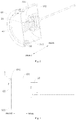
FIG. 1 is a perspective view of a photographing device for a vehicle according to a first embodiment of the present disclosure. -
FIG. 2 is a cutaway view of the photographing device inFIG. 1 . -
FIG. 3 is a side view of the photographing device inFIG. 1 . -
FIG. 4 is a sectional view of the photographing device inFIG. 1 . -
FIG. 5 is a rear view of the photographing device inFIG. 1 . -
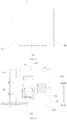
FIG. 6 is a side view of a photographing device for a vehicle according to a second embodiment of the present disclosure. -
FIG. 7 is a sectional view of the photographing device inFIG. 6 . -
FIG. 8 is a front view of a retaining ring of a photographing device for a vehicle according to an embodiment of the present disclosure. -
FIG. 9 is a side view of the retaining ring inFIG. 8 . -
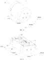
FIG. 10 is a perspective view of a photographing device for a vehicle according to a third embodiment of the present disclosure. -
FIG. 11 is a cutaway view of the photographing device inFIG. 10 . -
FIG. 12 is a front view of the photographing device inFIG. 10 . -
FIG. 13 is a sectional view of the photographing device inFIG. 10 . - photographing
device 1 for vehicle,base 10,cylindrical member 101,chamber 1011,cover plate 102,camera 20,lens holder 30, firstannular groove 301,transparent lens 40,driving assembly 50,motor 501,gear 502,gear ring 503, first compressedgas nozzle 504,blade 505,retaining ring 60,water guiding groove 601,guide seat 70, secondannular groove 701. - Exemplary embodiments of the present disclosure will be illustrated below with reference to the accompanying drawings, which include various details of the embodiments of the present disclosure to facilitate understanding, and which should be considered to be merely exemplary. Therefore, a person skilled in the art should recognize that various changes and modifications can be made to the embodiments described herein without departing from the scope of the present disclosure. For clarity and conciseness, description about well-known functions and structures will be omitted.
- A photographing device for a vehicle according to embodiments of the present disclosure will be described below with reference to
FIGS. 1-13 . - As shown in
FIGS. 1-13 , thephotographing device 1 according to the embodiments of the present disclosure includes abase 10, acamera 20, alens holder 30, atransparent lens 40, and adriving assembly 50. - As shown in
FIGS. 2 and4 , thecamera 20 is mounted on thebase 10; thelens holder 30 is mounted on thebase 10 and is rotatable relative to thebase 10; thetransparent lens 40 is mounted on thelens holder 30 and arranged opposite to thecamera 20; thedriving assembly 50 is connected with thelens holder 30 to drive thelens holder 30 to rotate relative to thebase 10. Specifically, as shown inFIGS. 2 and4 , a rear end of thecamera 20 is connected to thebase 10, and thelens holder 30 is arranged on a front side of a lens of thecamera 20, so that thecamera 20 can perform clear imaging through thetransparent lens 40 mounted on thelens holder 30. - Therefore, according to the technical solution of the embodiments of the present disclosure, by providing the lens holder which is rotatable relative to the base and on which the transparent lens is mounted, and by providing the driving assembly for driving the lens holder to rotate relative to the base, the lens holder can be driven to rotate using the driving assembly, and the transparent lens can be brought into rotation. During the rotation, a centrifugal force of the transparent lens can hurl out raindrops on the transparent lens, thereby making a surface of the transparent lens maintain a better light transmission effect and improving the reliability of the camera's clear imaging. Moreover, the raindrops on the surface of the transparent lens can be removed at any time during driving to reduce safety hazards during driving.
- In some embodiments, as shown in
FIGS. 1-7 , thebase 10 includes acylindrical member 101 and acover plate 102. Thecylindrical member 101 has achamber 1011, and a first end (a front end as shown inFIG. 2 ) of thecylindrical member 101 is opened to make a first end of thechamber 1011 open. Thecover plate 102 is arranged at a second end (a rear end as shown inFIG. 2 ) of thecylindrical member 101 to cover a second end of thechamber 1011. Thecamera 20 is mounted on thecover plate 102 and located in thechamber 1011. Thelens holder 30 is mounted at the first end of thecylindrical member 101 to cover, together with thetransparent lens 40, the first end of thechamber 1011. - Specifically, as shown in
FIGS. 1-7 , thecylindrical member 101 extends in a front-rear direction, a rear end of thechamber 1011 of thecylindrical member 101 is open, and the rear end of thecylindrical member 101 is provided with thecover plate 102 to cover the rear end of thechamber 1011. Preferably, thecylindrical member 101 and thecover plate 102 are integrally formed, that is, thebase 10 is an integrally formed member. It should be noted that thecylindrical member 101 and thecover plate 102 may also be two separate structural members. After thecylindrical member 101 and thecover plate 102 are formed separately, thecover plate 102 is connected to the rear end of thecylindrical member 101 to form thebase 10. - A front end of the
chamber 1011 of thecylindrical member 101 is open, and thelens holder 30 is mounted at the front end (the first end) of thecylindrical member 101 and provided with a through hole that runs through thelens holder 30 in the front-rear direction. Thetransparent lens 40 is mounted in the through hole and opposite to thecamera 20 in the front-rear direction. Thelens holder 30 and thetransparent lens 40 together shield the front end of thechamber 1011. Therefore, a relatively sealed space (chamber) can be formed by the cover plate, the cylindrical member, the lens holder, and the transparent lens, and external water vapor or dust can be prevented from invading the chamber, which is beneficial for clear imaging of the camera in the chamber and enhances the damage resistance. - In some embodiments, as shown in
FIGS. 1-9 , thephotographing device 1 further includes aretaining ring 60. Theretaining ring 60 is arranged at the first end of thecylindrical member 101, and a part of thelens holder 30 is clamped between theretaining ring 60 and the first end of thecylindrical member 101. Therefore, the clamping by the retaining ring and the cylindrical member can be used to prevent the lens holder from moving in the front-rear direction, and the assembling reliability of the transparent lens can be improved. In the embodiment shown inFIG. 1 , theretaining ring 60 is a circular ring. It can be understood that the shape of theretaining ring 60 is not limited to that shown inFIG. 1 , and instead, theretaining ring 60 can be provided suitably according to the opening shape of thecylindrical member 101. - In some embodiments, as shown in
FIGS. 8 and 9 , theretaining ring 60 is provided with awater guiding groove 601 that has a length extending along a peripheral direction of theretaining ring 60, a width extending along a radial direction of theretaining ring 60, and a depth extending along an axial direction of theretaining ring 60. In other words, thewater guiding groove 601 is a groove extending along the peripheral direction of theretaining ring 60 and having a certain depth in the axial direction of theretaining ring 60, so that the water guiding groove can be used to drain the raindrops hurled out by the transparent lens to the outside of the photographing device. - Specifically, as shown in
FIGS. 4 ,7 ,8 and 9 , thewater guiding groove 601 extends along the peripheral direction of theretaining ring 60 to form the length of thewater guiding groove 601. Thewater guiding groove 601 extends forward from a rear end surface of theretaining ring 60 to form the depth of thewater guiding groove 601 and extends inward from an outer peripheral surface of theretaining ring 60 to form the width of thewater guiding groove 601. - Further, as shown in
FIGS. 1-9 , there are a plurality ofwater guiding grooves 601, and the plurality ofwater guiding grooves 601 are arranged at intervals along the peripheral direction of the retainingring 60. Thus, the efficiency and reliability of guiding water by the water guiding groove can be improved. - In some embodiments, as shown in
FIG. 4 , the drivingassembly 50 includes amotor 501, agear 502, and agear ring 503. Themotor 501 is mounted on thecover plate 102 and located outside thechamber 1011. Thegear 502 is located in thechamber 1011 and connected to an output shaft of themotor 501. Thegear ring 503 is mounted on thelens holder 30 and arranged in thechamber 1011, and thegear ring 503 meshes with thegear 502. Specifically, a front end of themotor 501 is mounted to a rear end surface of thecover plate 102. The output shaft of themotor 501 extends forward into thechamber 1011, and thegear 502 is connected to a front end of the output shaft. Thegear ring 503 extends along a peripheral direction of thelens holder 30 and arranged on a rear side of thelens holder 30. - The output shaft of the motor can drive the gear to rotate, and the engagement between the gear and the gear ring can drive the
gear ring 503 to rotate. In turn, the rotation of the gear ring can drive the lens holder to rotate, so that the transparent lens rotates along with the lens holder to hurl out the raindrops on the surface of the transparent lens. - In addition, in the embodiment shown in
FIG. 4 , thebase 10, thelens holder 30, the retainingring 60, and thegear 502 can be made of engineering plastics with self-lubricity, abrasion resistance, and good mechanical properties, so as to reduce the abrasion of components and parts of the photography device during the rotation of the lens holder. Thetransparent lens 40 may be spherical, which can facilitate the hurl-out of raindrops. - It can be understood that the driving
assembly 50 is not limited to the embodiments shown inFIGS. 1-4 . For example, in other embodiments, as shown inFIGS. 6 and 7 , the drivingassembly 50 includes a firstcompressed gas nozzle 504 and a plurality ofblades 505 mounted on thelens holder 30. The firstcompressed gas nozzle 504 and theblades 505 are arranged in thechamber 1011. The firstcompressed gas nozzle 504 can eject compressed gas to theblades 505 to drive theblades 505 to rotate. As a result, the compressed gas ejected by the first compressed gas nozzle can be used as power to drive the blades to rotate, and in turn the blades are used to drive the lens holder to rotate, so that the transparent lens can rotate and hurl out raindrops. In addition, the compressed gas ejected by the first compressed gas nozzle can also remove mist in the chamber and improve the imaging clarity of the camera. - In an embodiment shown in
FIG. 7 , thebase 10, thelens holder 30, and the retainingring 60 can be made of engineering plastics with self-lubrication, abrasion resistance, and good mechanical properties, to reduce the wear and tear of parts of the photographing device when the lens holder rotates. - The structures of the
base 10 and thetransparent lens 40 are not limited to the embodiments shown inFIGS. 1-7 . For example, in other embodiments, as shown inFIGS. 10-13 , thetransparent lens 40 is substantially cylindrical, thelens holder 30 is provided with a firstannular groove 301, a first end of thetransparent lens 40 is fitted in the firstannular groove 301, and thebase 10 is arranged in thetransparent lens 40. Specifically, as shown inFIG. 10 , thetransparent lens 40 is a cylindrical structural member extending in a left-right direction (i.e., the left-right direction as shown inFIG. 10 ), and thecamera 20 is mounted on thebase 10. The substantially cylindrical transparent lens has a large light transmission range and high light transmission intensity, which is conducive to the clear imaging of the camera. Thelens holder 30 is mounted at a right end of thetransparent lens 40, the firstannular groove 301 extends along the peripheral direction of thelens holder 30 and is opened leftwards, and the right end of thetransparent lens 40 can be inserted into the firstannular groove 301, thereby improving the convenience of assembling the lens holder and the transparent lens. - In some specific embodiments, as shown in
FIG. 10, FIG. 11 andFIG. 13 , the photographingdevice 1 further includes aguide seat 70 connected to thebase 10 and arranged opposite to thelens holder 30. Theguide seat 70 is provided with a secondannular groove 701, and a second end of thetransparent lens 40 is fitted in the secondannular groove 701. Specifically, theguide seat 70 is disposed at a left end (i.e., the second end) of thetransparent lens 40, theguide seat 70 is mounted on thebase 10, the secondannular groove 701 extends in a peripheral direction of theguide seat 70 and is opened rightwards, and the left end of thetransparent lens 40 is suitable to be inserted into the secondannular groove 701. - Therefore, the way of assembling the guide seat and the transparent lens can be simplified, the rotation of the transparent lens can be guided by the second annular groove, and the guide seat, the transparent lens, and the lens holder can constitute a closed receiving space to protect the camera in the transparent lens from being corroded by moisture and dust.
- In some specific embodiments, as shown in
FIG. 10 and FIG. 11 , thelens holder 30 and theguide seat 70 are both substantially cylindrical, which facilitates the adaptation to the substantially cylindricaltransparent lens 40. The drivingassembly 50 includes themotor 501, the output shaft of themotor 501 is connected to thelens holder 30, and themotor 501 is suitable to drive thelens holder 30 to rotate. In turn, thelens holder 30 can drive thetransparent lens 40 to rotate to hurl out raindrops on the surface of thetransparent lens 40. - In the embodiment shown in
FIGS. 10-13 , thebase 10, thelens holder 30, and the lens guideseat 70 can be made of engineering plastics with self-lubrication, abrasion resistance, and good mechanical properties, to reduce the wear and tear of parts of the photographing device when the lens holder rotates. - In some embodiments, the photographing
device 1 further includes a second compressed gas nozzle (not shown) that can eject compressed gas toward thetransparent lens 40 from the outside of thetransparent lens 40. Therefore, the compressed gas ejected from the second compressed gas nozzle can be used to blow away stains on an outer surface of the transparent lens, which is further conducive to the clear imaging of the camera. - In some embodiments, the photographing
device 1 further includes a third compressed gas nozzle (not shown) that can eject compressed gas toward the transparent lens from the inside of the transparent lens. Therefore, the compressed gas ejected from the third compressed gas nozzle can be used to remove the mist within the photographing device, and further improve the imaging clarity. In the embodiment shown inFIGS. 6 and 7 , the third compressed gas nozzle may not be provided, and a defogging effect can be achieved when the firstcompressed gas nozzle 504 drives theblades 505 to rotate. - In some specific embodiments, the photographing
device 1 further includes a heating component (not shown) that can be used to heat the compressed gas in the third compressed gas nozzle to defrost and avoid condensation on the surface of the transparent lens. - In some embodiments, the photographing
device 1 further includes a cleaning liquid nozzle (not shown) that can spray a cleaning liquid to thetransparent lens 40 from the outside of thetransparent lens 40. Therefore, the cleaning liquid can be used to remove stains on the outer surface of the transparent lens and make the camera imaging clearer. - In some embodiments, the photographing
device 1 further includes a wiper assembly (not shown) that can cooperate with the cleaning liquid nozzle to remove stains on the surface of thetransparent lens 40. It can be understood that the wiper assembly can make the cleaning liquid evenly spread on the surface of the transparent lens and can wipe back and forth on the surface of the transparent lens to improve a cleaning effect of the cleaning liquid. - A photographing device for a vehicle according to a specific example of the present disclosure will be described below with reference to
FIGS. 1-5 and8-9 . - As shown in
FIGS. 1 ,2 and4 , the photographingdevice 1 includes abase 10, acamera 20, alens holder 30, atransparent lens 40, and a drivingassembly 50. As shown inFIG. 2 , thebase 10 includes acylindrical member 101 extending in a front-rear direction (e.g., the front-rear direction shown inFIG. 2 ) and having achamber 1011. A rear end of thechamber 1011 of thecylindrical member 101 is open, and acover plate 102 is provided at a rear end of thecylindrical member 101 to cover the rear end of thechamber 1011. - A front end of the
chamber 1011 of thecylindrical member 101 is open, and thelens holder 30 is mounted at a front end of thecylindrical member 101. Thelens holder 30 is provided with a through hole that runs through thelens holder 30 in the front-rear direction. Thetransparent lens 40 is mounted in the through hole and opposite to thecamera 20 in the front-rear direction. Thelens holder 30 and thetransparent lens 40 together shield the front end of thechamber 1011. - As shown in
FIG. 2 , the photographingdevice 1 includes anannular retaining ring 60 mounted at the front end of thecylindrical member 101 and located on a front side of thelens holder 30, and an edge of thelens holder 30 is sandwiched between theannular retaining ring 60 and the front end of thecylindrical member 101. As shown inFIGS. 8 and 9 , theannular retaining ring 60 is provided with awater guiding groove 601 that extends along a peripheral direction of the retainingring 60 and has a certain width in a radial direction of the retainingring 60 and a certain depth in a front-rear direction of the retainingring 60. There are a plurality ofwater guiding grooves 601 evenly spaced along the peripheral direction of the retainingring 60. - As shown in
FIG. 4 , the drivingassembly 50 includes amotor 501, agear 502, and agear ring 503. A front end of themotor 501 is mounted to a rear end surface of thecover plate 102. An output shaft of themotor 501 extends forward into thechamber 1011. Thegear 502 and thegear ring 503 are both located in thechamber 1011. Thegear 502 is connected to a front end of the output shaft. Thegear ring 503 extends in a peripheral direction of thelens holder 30 and is arranged on a rear side of thelens holder 30. Thegear 502 meshes with thegear ring 503. - A photographing device for a vehicle according to another embodiment of the present disclosure will be described below with reference to
FIGS. 6-9 . - As shown in
FIGS. 6 and 7 , the photographingdevice 1 includes abase 10, acamera 20, alens holder 30, atransparent lens 40,blades 505, and a firstcompressed gas nozzle 504. - As shown in
FIG. 7 , theblades 505 are located in thechamber 1011, and theblades 505 are distributed along a peripheral direction of thelens holder 30 and arranged on a rear side of thelens holder 30. The firstcompressed gas nozzle 504 passes through and is connected to thecover plate 102. A front end of the firstcompressed gas nozzle 504 is located in thechamber 1011, and a rear end of the firstcompressed gas nozzle 504 extends out of thechamber 1011, that is, the rear end of the firstcompressed gas nozzle 504 is located outside thebase 10, to facilitate the docking with external ventilation equipment. The front end of the firstcompressed gas nozzle 504 has a jet orifice that is opened toward theblades 505. - Other structures and operations of the photographing device shown in
FIGS. 6 and 7 may be the same as those in the embodiments shown inFIGS. 1-5 and will not be described in detail here. - A photographing
device 1 for a vehicle according to another embodiment of the present disclosure will be described below with reference toFIGS. 10-13 . - As shown in
FIGS. 10-13 , the photographingdevice 1 includes abase 10, acamera 20, alens holder 30, atransparent lens 40, and alens guide seat 70. As shown inFIGS. 10 and 11 , thetransparent lens 40 is a cylindrical structural member extending in a left-right direction (e.g. the left-right direction as shown inFIG. 10 ), a right end of thetransparent lens 40 is also open, and theguide seat 70 is mounted at the right end of thetransparent lens 40 to block the open right end. A left end of thetransparent lens 40 is open, and thelens holder 30 is mounted at the left end of thetransparent lens 40 to block the open left end. Thebase 10 is arranged in thetransparent lens 40, and a right end of thebase 10 is connected with theguide base 70. Thecamera 20 is mounted on thebase 10. - As shown in
FIG. 11 , the photographingdevice 1 includes amotor 501 located in thetransparent lens 40 and mounted on thebase 10, and an output shaft of themotor 501 is connected to thelens holder 30. - As shown in
FIGS. 11 and13 , thelens holder 30 is provided with a firstannular groove 301 that extends along a peripheral direction of thelens holder 30. The firstannular groove 301 is opened rightwards, and the left end of thetransparent lens 40 is inserted into the firstannular groove 301. - As shown in
FIGS. 11 and13 , theguide seat 70 is provided with a secondannular groove 701 that extends in a peripheral direction of theguide seat 70. The secondannular groove 701 is opened leftwards, and the right end of thetransparent lens 40 is suitable to be inserted into the secondannular groove 701. - In the description of the present disclosure, it should be understood that terms such as "front," "rear," "inner," "outer," "axial," "radial," "circumferential" and the like should be constructed to refer to the orientation or position as then described or as shown in the drawings under discussion. These terms are for convenience and simplification of description and do not indicate or imply that the device or element referred to must have a particular orientation, or be constructed and operated in a particular orientation, so these terms shall not be construed to limit the present disclosure.
- In addition, terms such as "first" and "second" are used herein for purposes of description and are not intended to indicate or imply relative importance or significance or to imply the number of indicated technical features. Thus, the feature defined with "first" and "second" may comprise one or more of this feature. In the description of the present disclosure, the term "a plurality of' means at least two, such as two or three, unless specified otherwise.
- In the present disclosure, unless specified or limited otherwise, the terms "mounted," "connected," "coupled," "fixed" and the like are used broadly, and may be, for example, fixed connections, detachable connections, or integral connections; may also be mechanical or electrical connections; may also be direct connections or indirect connections via intervening structures; may also be inner communications of two elements, which can be understood by those skilled in the art according to specific situations.
- In the present disclosure, unless specified or limited otherwise, a structure in which a first feature is "on" or "below" a second feature may include an embodiment in which the first feature is in direct contact with the second feature, and may also include an embodiment in which the first feature and the second feature are not in direct contact with each other, but are contacted via an additional feature formed therebetween. Furthermore, a first feature "on," "above," or "on top of' a second feature may include an embodiment in which the first feature is right or obliquely "on," "above," or "on top of' the second feature, or just means that the first feature is at a height higher than that of the second feature; while a first feature "below," "under," or "on bottom of' a second feature may include an embodiment in which the first feature is right or obliquely "below," "under," or "on bottom of' the second feature, or just means that the first feature is at a height lower than that of the second feature.
- In the description of the present specification, reference throughout this specification to "an embodiment," "some embodiments," "an example," "a specific example," "some examples" or the like means that a particular feature, structure, material, or characteristic described in connection with the embodiment or example is included in at least one embodiment or example of the present disclosure. In the specification, the appearances of the above-mentioned terms are not necessarily referring to the same embodiment or example. Furthermore, the particular features, structures, materials, or characteristics described can be combined in any suitable manner in one or more embodiments or examples.
- The above specific embodiments do not limit the protection scope of this application. It should be appreciated by those skilled in the art that various modifications, combinations, subcombinations, and substitutions can be made according to design requirements and other factors. Any modifications, equivalent substitutions and improvements made within the principles of this application shall be included within the protection scope of this application.
Claims (15)
- A photographing device (1) for a vehicle, comprising:a base (10);a camera (20) mounted on the base (10);a lens holder (30) mounted on the base (10) and rotatable relative to the base (10);a transparent lens (40) mounted on the lens holder (30) and arranged opposite to the camera (20); anda driving assembly (50) connected with the lens holder (30) to drive the lens holder (30) to rotate relative to the base (10).
- The photographing device (1) according to claim 1, wherein the base (10) comprises a cylindrical member (101) and a cover plate (102); the cylindrical member (101) has a chamber (1011), a first end of the cylindrical member (101) is opened to make a first end of the chamber (1011) open, and the cover plate (102) is arranged at a second end of the cylindrical member (101) to cover a second end of the chamber (1011); the camera (20) is mounted on the cover plate (102) and located in the chamber (1011); the lens holder (30) is mounted at the first end of the cylindrical member (101) to cover, together with the transparent lens (40), the first end of the chamber (1011).
- The photographing device (1) according to claim 2, further comprising a retaining ring (60) arranged at the first end of the cylindrical member (101), a part of the lens holder (30) being clamped between the retaining ring (60) and the first end of the cylindrical member (101).
- The photographing device (1) according to claim 3, wherein the retaining ring (60) is provided with a water guiding groove (601) that has a length extending along a peripheral direction of the retaining ring (60), a width extending along a radial direction of the retaining ring (60), and a depth extending along an axial direction of the retaining ring (60).
- The photographing device (1) according to claim 4, wherein a plurality of water guiding grooves (601) are arranged at intervals along the peripheral direction of the retaining ring (60).
- The photographing device (1) according to any one of claims 2 to 5, wherein the driving assembly (50) comprises a motor (501), a gear (502), and a gear ring (503); the motor (501) is mounted on the cover plate (102) and located outside the chamber (1011); the gear (502) is located in the chamber (1011) and connected to an output shaft of the motor (501); the gear ring (503) is mounted on the lens holder (30) and arranged in the chamber (1011); and the gear ring (503) meshes with the gear (502).
- The photographing device (1) according to any one of claims 2 to 6, wherein the driving assembly (50) comprises a first compressed gas nozzle (504) and a plurality of blades (505) mounted on the lens holder (30); the first compressed gas nozzle (504) and the blades (505) are arranged in the chamber (1011); the first compressed gas nozzle (504) ejects compressed gas to the blades (505) to drive the blades (505) to rotate.
- The photographing device (1) according to any one of claims 1 to 7, wherein the transparent lens (40) is substantially cylindrical, the lens holder (30) is provided with a first annular groove (301), a first end of the transparent lens (40) is fitted in the first annular groove (301), and the base (10) is arranged in the transparent lens (40).
- The photographing device according to claim 8, further comprising a guide seat (70) connected to the base (10) and arranged opposite to the lens holder (30), wherein the guide seat (70) is provided with a second annular groove (701), and a second end of the transparent lens (40) is fitted in the second annular groove (701).
- The photographing device (1) according to claim 9, wherein the lens holder (30) and the guide seat (70) are both substantially cylindrical; the driving assembly (50) comprises a motor (501), and an output shaft of the motor (501) is connected to the lens holder (30).
- The photographing device (1) according to any one of claims 1 to 10, further comprising a second compressed gas nozzle that ejects compressed gas toward the transparent lens (40) from an outer side of the transparent lens (40).
- The photographing device (1) according to any one of claims 1 to 6 and claims 8 to 10, further comprising a third compressed gas nozzle that ejects compressed gas toward the transparent lens (40) from an inner side of the transparent lens (40).
- The photographing device (1) according to claim 12, further comprising a heating component used to heat the compressed gas in the third compressed gas nozzle to defrost.
- The photographing device (1) according to any one of claims 1 to 13, further comprising a cleaning liquid nozzle that sprays a cleaning liquid to the transparent lens (40) from an outer side of the transparent lens (40).
- The photographing device (1) according to claim 14, further comprising a wiper assembly that cooperates with the cleaning liquid nozzle to remove stains on a surface of the transparent lens (40).
Applications Claiming Priority (2)
| Application Number | Priority Date | Filing Date | Title |
|---|---|---|---|
| CN202010479770.4A CN111572462A (en) | 2020-05-29 | 2020-05-29 | Photographing apparatus for vehicle |
| CN202020962160.5U CN212766046U (en) | 2020-05-29 | 2020-05-29 | Photographing apparatus for vehicle |
Publications (2)
| Publication Number | Publication Date |
|---|---|
| EP3823265A2 true EP3823265A2 (en) | 2021-05-19 |
| EP3823265A3 EP3823265A3 (en) | 2021-09-01 |
Family
ID=75203016
Family Applications (1)
| Application Number | Title | Priority Date | Filing Date |
|---|---|---|---|
| EP21164316.8A Pending EP3823265A3 (en) | 2020-05-29 | 2021-03-23 | Photographing device for vehicle |
Country Status (4)
| Country | Link |
|---|---|
| US (1) | US11938868B2 (en) |
| EP (1) | EP3823265A3 (en) |
| JP (1) | JP7278328B2 (en) |
| KR (1) | KR102466360B1 (en) |
Families Citing this family (1)
| Publication number | Priority date | Publication date | Assignee | Title |
|---|---|---|---|---|
| KR102567624B1 (en) | 2021-09-09 | 2023-08-16 | 한국전기연구원 | Silicon carbide crystal defect location analysis method using non-destructive analysis method and analysis device and computer program including the same |
Family Cites Families (21)
| Publication number | Priority date | Publication date | Assignee | Title |
|---|---|---|---|---|
| JPS6260022A (en) | 1985-09-10 | 1987-03-16 | Nec Corp | Keyboard |
| JPS63166141U (en) * | 1987-04-20 | 1988-10-28 | ||
| JPH09106973A (en) | 1995-10-09 | 1997-04-22 | Dainippon Screen Mfg Co Ltd | Substrate cleaner |
| JPH09292656A (en) | 1996-02-27 | 1997-11-11 | Fuji Photo Optical Co Ltd | Water droplet removing device for camera lens |
| JP2001249376A (en) | 2000-03-07 | 2001-09-14 | Shinji Kiyama | Lens hood adaptable as rain cover |
| KR100640867B1 (en) | 2004-09-11 | 2006-11-02 | 엘지전자 주식회사 | A camera lens polution preventing device |
| JP2008165093A (en) | 2006-12-28 | 2008-07-17 | Masakazu Kajima | Deposit removing device |
| DE102008027430A1 (en) | 2008-06-09 | 2009-02-19 | Daimler Ag | Protection device for image recording unit of vehicle, has transparent disk arranged before image recording unit in moving manner, where cleaning device is formed from wash water-feeding unit, wash element and wiper element |
| KR101025220B1 (en) | 2009-04-08 | 2011-04-07 | (주)모나드아이엔씨 | An apparatus for washing of the transparency panel |
| JP2011155468A (en) | 2010-01-27 | 2011-08-11 | Nippon Soken Inc | Optical sensor device for vehicle |
| CN103129473A (en) * | 2011-11-30 | 2013-06-05 | 昆达电脑科技(昆山)有限公司 | Front-view device |
| DE102013020894B3 (en) | 2013-12-11 | 2015-04-09 | Mekra Lang Gmbh & Co. Kg | Camera with heating element |
| JP6327514B2 (en) | 2014-03-25 | 2018-05-23 | 三菱自動車工業株式会社 | Electronic mirror lens cover cleaning device |
| US11165932B2 (en) | 2015-12-22 | 2021-11-02 | Kyocera Corporation | Imaging apparatus, imaging system, vehicle and foreign matter determination method |
| JP6711045B2 (en) | 2016-03-16 | 2020-06-17 | 三菱自動車工業株式会社 | Water drop removal device for vehicle-mounted imaging device |
| FR3054459B1 (en) | 2016-07-28 | 2020-09-04 | Valeo Systemes Dessuyage | PROTECTION DEVICE FOR AN OPTICAL SENSOR AND DRIVING ASSISTANCE SYSTEM INCLUDING AN OPTICAL SENSOR |
| CN106347316B (en) * | 2016-10-31 | 2018-05-25 | 赵福林 | One kind being capable of self-cleaning motor vehicle driving auxiliary camera |
| FR3058652B1 (en) | 2016-11-17 | 2021-10-15 | Valeo Systemes Dessuyage | PROTECTION DEVICE FOR AN OPTICAL SENSOR, DRIVING ASSISTANCE SYSTEM AND ASSOCIATED CLEANING PROCEDURE |
| JP2019207313A (en) | 2018-05-29 | 2019-12-05 | キヤノン株式会社 | Imaging apparatus |
| JP2020016862A (en) | 2018-07-27 | 2020-01-30 | 京セラ株式会社 | Camera device, camera system, movable body, and method for manufacturing camera device |
| CN115356821A (en) * | 2022-09-14 | 2022-11-18 | 业成科技(成都)有限公司 | Camera module adjusting jig and camera module adjusting device |
-
2020
- 2020-12-22 US US17/131,393 patent/US11938868B2/en active Active
-
2021
- 2021-03-23 KR KR1020210037428A patent/KR102466360B1/en active IP Right Grant
- 2021-03-23 EP EP21164316.8A patent/EP3823265A3/en active Pending
- 2021-05-27 JP JP2021088854A patent/JP7278328B2/en active Active
Also Published As
| Publication number | Publication date |
|---|---|
| JP7278328B2 (en) | 2023-05-19 |
| US11938868B2 (en) | 2024-03-26 |
| KR20210040004A (en) | 2021-04-12 |
| JP2021131573A (en) | 2021-09-09 |
| EP3823265A3 (en) | 2021-09-01 |
| KR102466360B1 (en) | 2022-11-10 |
| US20210370844A1 (en) | 2021-12-02 |
Similar Documents
| Publication | Publication Date | Title |
|---|---|---|
| US7954198B2 (en) | Windshield wiper assembly with unitary arm and post | |
| CN106347316B (en) | One kind being capable of self-cleaning motor vehicle driving auxiliary camera | |
| EP3823265A2 (en) | Photographing device for vehicle | |
| EP3508387B1 (en) | Cleaner and vehicle provided with cleaner | |
| US11535203B2 (en) | Air cleaner for vehicles | |
| US9838653B2 (en) | Roof mounted imager module | |
| US7086692B2 (en) | Wheel house shell for a motor vehicle | |
| KR102509812B1 (en) | Method and apparatus for removing material from the surface of an object | |
| US20150208886A1 (en) | Liquid aspirator for drawing off and sucking up liquids | |
| US20220250586A1 (en) | Windscreen wiper system for a motor vehicle | |
| US20200253438A1 (en) | Cleaner head | |
| JP6997179B2 (en) | An air scoop to orient the airflow over the camera lens | |
| EP2727190B1 (en) | Device for electrically coupling an electric compressor | |
| US20140201938A1 (en) | Wiper Blade Apparatus Including Fool-Proof Assembly Structure | |
| EP3369632B1 (en) | Washer nozzle arrangement structure | |
| CN212766046U (en) | Photographing apparatus for vehicle | |
| CN109394069B (en) | Dust collector air outlet plate with unlocking and ejection integrated mechanism and dust collector | |
| FR2922493A1 (en) | Anti-recycling air partition and component i.e. front bumper face-bar, assembly for motor vehicle, has component with rib that is superimposed on edge of part and is arranged nearer to edge, where component is provided adjacent to partition | |
| CN215227374U (en) | Drive installation component and dish washer that has it | |
| US20210053533A1 (en) | Windscreen wiper connector assembly for a vehicle | |
| KR100778571B1 (en) | A wiper ahm assembly improved assembly structure | |
| US20050077382A1 (en) | Vehicle window clearing device | |
| US9731687B2 (en) | Wiper apparatus having integrally formed washer nozzle | |
| US11858474B2 (en) | Wind deflector for a window wiper system of a motor vehicle | |
| US20240149837A1 (en) | Sensor cleaning apparatus for a vehicle |
Legal Events
| Date | Code | Title | Description |
|---|---|---|---|
| PUAI | Public reference made under article 153(3) epc to a published international application that has entered the european phase |
Free format text: ORIGINAL CODE: 0009012 |
|
| STAA | Information on the status of an ep patent application or granted ep patent |
Free format text: STATUS: THE APPLICATION HAS BEEN PUBLISHED |
|
| AK | Designated contracting states |
Kind code of ref document: A2 Designated state(s): AL AT BE BG CH CY CZ DE DK EE ES FI FR GB GR HR HU IE IS IT LI LT LU LV MC MK MT NL NO PL PT RO RS SE SI SK SM TR |
|
| PUAL | Search report despatched |
Free format text: ORIGINAL CODE: 0009013 |
|
| AK | Designated contracting states |
Kind code of ref document: A3 Designated state(s): AL AT BE BG CH CY CZ DE DK EE ES FI FR GB GR HR HU IE IS IT LI LT LU LV MC MK MT NL NO PL PT RO RS SE SI SK SM TR |
|
| RIC1 | Information provided on ipc code assigned before grant |
Ipc: H04N 5/225 20060101AFI20210729BHEP Ipc: B60R 1/00 20060101ALI20210729BHEP Ipc: G03B 17/00 20210101ALI20210729BHEP Ipc: B60S 1/02 20060101ALI20210729BHEP Ipc: B60S 1/54 20060101ALI20210729BHEP Ipc: B60S 1/56 20060101ALI20210729BHEP Ipc: G01S 17/00 20200101ALI20210729BHEP Ipc: G02B 27/00 20060101ALI20210729BHEP |
|
| RAP1 | Party data changed (applicant data changed or rights of an application transferred) |
Owner name: APOLLO INTELLIGENT CONNECTIVITY (BEIJING) TECHNOLOGY CO., LTD. |
|
| STAA | Information on the status of an ep patent application or granted ep patent |
Free format text: STATUS: REQUEST FOR EXAMINATION WAS MADE |
|
| 17P | Request for examination filed |
Effective date: 20220224 |
|
| RBV | Designated contracting states (corrected) |
Designated state(s): AL AT BE BG CH CY CZ DE DK EE ES FI FR GB GR HR HU IE IS IT LI LT LU LV MC MK MT NL NO PL PT RO RS SE SI SK SM TR |