EP3823129B1 - Battery system, and method of allocating can id - Google Patents
Battery system, and method of allocating can id Download PDFInfo
- Publication number
- EP3823129B1 EP3823129B1 EP20207555.2A EP20207555A EP3823129B1 EP 3823129 B1 EP3823129 B1 EP 3823129B1 EP 20207555 A EP20207555 A EP 20207555A EP 3823129 B1 EP3823129 B1 EP 3823129B1
- Authority
- EP
- European Patent Office
- Prior art keywords
- battery
- controller
- station
- battery pack
- signal
- Prior art date
- Legal status (The legal status is an assumption and is not a legal conclusion. Google has not performed a legal analysis and makes no representation as to the accuracy of the status listed.)
- Active
Links
- 238000000034 method Methods 0.000 title claims description 17
- 230000004044 response Effects 0.000 claims description 31
- 238000001514 detection method Methods 0.000 claims description 25
- 230000002618 waking effect Effects 0.000 claims description 12
- 230000008859 change Effects 0.000 claims description 6
- 238000004891 communication Methods 0.000 description 41
- 206010068065 Burning mouth syndrome Diseases 0.000 description 8
- 238000007599 discharging Methods 0.000 description 5
- 230000005540 biological transmission Effects 0.000 description 4
- 230000001276 controlling effect Effects 0.000 description 3
- 238000012544 monitoring process Methods 0.000 description 3
- 230000008878 coupling Effects 0.000 description 2
- 238000010168 coupling process Methods 0.000 description 2
- 238000005859 coupling reaction Methods 0.000 description 2
- 238000010586 diagram Methods 0.000 description 2
- 238000004146 energy storage Methods 0.000 description 2
- 230000006870 function Effects 0.000 description 2
- WHXSMMKQMYFTQS-UHFFFAOYSA-N Lithium Chemical compound [Li] WHXSMMKQMYFTQS-UHFFFAOYSA-N 0.000 description 1
- HBBGRARXTFLTSG-UHFFFAOYSA-N Lithium ion Chemical compound [Li+] HBBGRARXTFLTSG-UHFFFAOYSA-N 0.000 description 1
- 239000002253 acid Substances 0.000 description 1
- 230000006978 adaptation Effects 0.000 description 1
- OJIJEKBXJYRIBZ-UHFFFAOYSA-N cadmium nickel Chemical compound [Ni].[Cd] OJIJEKBXJYRIBZ-UHFFFAOYSA-N 0.000 description 1
- 239000003990 capacitor Substances 0.000 description 1
- 125000004122 cyclic group Chemical group 0.000 description 1
- 229910052744 lithium Inorganic materials 0.000 description 1
- 229910001416 lithium ion Inorganic materials 0.000 description 1
- 238000012423 maintenance Methods 0.000 description 1
- 229910052987 metal hydride Inorganic materials 0.000 description 1
- 238000012986 modification Methods 0.000 description 1
- 230000004048 modification Effects 0.000 description 1
- 229910052759 nickel Inorganic materials 0.000 description 1
- PXHVJJICTQNCMI-UHFFFAOYSA-N nickel Substances [Ni] PXHVJJICTQNCMI-UHFFFAOYSA-N 0.000 description 1
- -1 nickel metal hydride Chemical class 0.000 description 1
- 229920000642 polymer Polymers 0.000 description 1
- 238000012545 processing Methods 0.000 description 1
- 230000001105 regulatory effect Effects 0.000 description 1
Images


Classifications
-
- H—ELECTRICITY
- H04—ELECTRIC COMMUNICATION TECHNIQUE
- H04L—TRANSMISSION OF DIGITAL INFORMATION, e.g. TELEGRAPHIC COMMUNICATION
- H04L12/00—Data switching networks
- H04L12/28—Data switching networks characterised by path configuration, e.g. LAN [Local Area Networks] or WAN [Wide Area Networks]
- H04L12/40—Bus networks
- H04L12/40006—Architecture of a communication node
- H04L12/40039—Details regarding the setting of the power status of a node according to activity on the bus
-
- H—ELECTRICITY
- H02—GENERATION; CONVERSION OR DISTRIBUTION OF ELECTRIC POWER
- H02J—CIRCUIT ARRANGEMENTS OR SYSTEMS FOR SUPPLYING OR DISTRIBUTING ELECTRIC POWER; SYSTEMS FOR STORING ELECTRIC ENERGY
- H02J13/00—Circuit arrangements for providing remote indication of network conditions, e.g. an instantaneous record of the open or closed condition of each circuitbreaker in the network; Circuit arrangements for providing remote control of switching means in a power distribution network, e.g. switching in and out of current consumers by using a pulse code signal carried by the network
- H02J13/00001—Circuit arrangements for providing remote indication of network conditions, e.g. an instantaneous record of the open or closed condition of each circuitbreaker in the network; Circuit arrangements for providing remote control of switching means in a power distribution network, e.g. switching in and out of current consumers by using a pulse code signal carried by the network characterised by the display of information or by user interaction, e.g. supervisory control and data acquisition systems [SCADA] or graphical user interfaces [GUI]
-
- H—ELECTRICITY
- H02—GENERATION; CONVERSION OR DISTRIBUTION OF ELECTRIC POWER
- H02J—CIRCUIT ARRANGEMENTS OR SYSTEMS FOR SUPPLYING OR DISTRIBUTING ELECTRIC POWER; SYSTEMS FOR STORING ELECTRIC ENERGY
- H02J7/00—Circuit arrangements for charging or depolarising batteries or for supplying loads from batteries
- H02J7/0013—Circuit arrangements for charging or depolarising batteries or for supplying loads from batteries acting upon several batteries simultaneously or sequentially
-
- H—ELECTRICITY
- H02—GENERATION; CONVERSION OR DISTRIBUTION OF ELECTRIC POWER
- H02J—CIRCUIT ARRANGEMENTS OR SYSTEMS FOR SUPPLYING OR DISTRIBUTING ELECTRIC POWER; SYSTEMS FOR STORING ELECTRIC ENERGY
- H02J7/00—Circuit arrangements for charging or depolarising batteries or for supplying loads from batteries
- H02J7/00032—Circuit arrangements for charging or depolarising batteries or for supplying loads from batteries characterised by data exchange
-
- G—PHYSICS
- G01—MEASURING; TESTING
- G01R—MEASURING ELECTRIC VARIABLES; MEASURING MAGNETIC VARIABLES
- G01R31/00—Arrangements for testing electric properties; Arrangements for locating electric faults; Arrangements for electrical testing characterised by what is being tested not provided for elsewhere
- G01R31/36—Arrangements for testing, measuring or monitoring the electrical condition of accumulators or electric batteries, e.g. capacity or state of charge [SoC]
- G01R31/396—Acquisition or processing of data for testing or for monitoring individual cells or groups of cells within a battery
-
- H—ELECTRICITY
- H02—GENERATION; CONVERSION OR DISTRIBUTION OF ELECTRIC POWER
- H02J—CIRCUIT ARRANGEMENTS OR SYSTEMS FOR SUPPLYING OR DISTRIBUTING ELECTRIC POWER; SYSTEMS FOR STORING ELECTRIC ENERGY
- H02J13/00—Circuit arrangements for providing remote indication of network conditions, e.g. an instantaneous record of the open or closed condition of each circuitbreaker in the network; Circuit arrangements for providing remote control of switching means in a power distribution network, e.g. switching in and out of current consumers by using a pulse code signal carried by the network
- H02J13/00002—Circuit arrangements for providing remote indication of network conditions, e.g. an instantaneous record of the open or closed condition of each circuitbreaker in the network; Circuit arrangements for providing remote control of switching means in a power distribution network, e.g. switching in and out of current consumers by using a pulse code signal carried by the network characterised by monitoring
-
- H—ELECTRICITY
- H02—GENERATION; CONVERSION OR DISTRIBUTION OF ELECTRIC POWER
- H02J—CIRCUIT ARRANGEMENTS OR SYSTEMS FOR SUPPLYING OR DISTRIBUTING ELECTRIC POWER; SYSTEMS FOR STORING ELECTRIC ENERGY
- H02J13/00—Circuit arrangements for providing remote indication of network conditions, e.g. an instantaneous record of the open or closed condition of each circuitbreaker in the network; Circuit arrangements for providing remote control of switching means in a power distribution network, e.g. switching in and out of current consumers by using a pulse code signal carried by the network
- H02J13/00006—Circuit arrangements for providing remote indication of network conditions, e.g. an instantaneous record of the open or closed condition of each circuitbreaker in the network; Circuit arrangements for providing remote control of switching means in a power distribution network, e.g. switching in and out of current consumers by using a pulse code signal carried by the network characterised by information or instructions transport means between the monitoring, controlling or managing units and monitored, controlled or operated power network element or electrical equipment
- H02J13/00016—Circuit arrangements for providing remote indication of network conditions, e.g. an instantaneous record of the open or closed condition of each circuitbreaker in the network; Circuit arrangements for providing remote control of switching means in a power distribution network, e.g. switching in and out of current consumers by using a pulse code signal carried by the network characterised by information or instructions transport means between the monitoring, controlling or managing units and monitored, controlled or operated power network element or electrical equipment using a wired telecommunication network or a data transmission bus
-
- H—ELECTRICITY
- H02—GENERATION; CONVERSION OR DISTRIBUTION OF ELECTRIC POWER
- H02J—CIRCUIT ARRANGEMENTS OR SYSTEMS FOR SUPPLYING OR DISTRIBUTING ELECTRIC POWER; SYSTEMS FOR STORING ELECTRIC ENERGY
- H02J7/00—Circuit arrangements for charging or depolarising batteries or for supplying loads from batteries
- H02J7/00032—Circuit arrangements for charging or depolarising batteries or for supplying loads from batteries characterised by data exchange
- H02J7/00036—Charger exchanging data with battery
-
- H—ELECTRICITY
- H02—GENERATION; CONVERSION OR DISTRIBUTION OF ELECTRIC POWER
- H02J—CIRCUIT ARRANGEMENTS OR SYSTEMS FOR SUPPLYING OR DISTRIBUTING ELECTRIC POWER; SYSTEMS FOR STORING ELECTRIC ENERGY
- H02J7/00—Circuit arrangements for charging or depolarising batteries or for supplying loads from batteries
- H02J7/00032—Circuit arrangements for charging or depolarising batteries or for supplying loads from batteries characterised by data exchange
- H02J7/00045—Authentication, i.e. circuits for checking compatibility between one component, e.g. a battery or a battery charger, and another component, e.g. a power source
-
- H—ELECTRICITY
- H02—GENERATION; CONVERSION OR DISTRIBUTION OF ELECTRIC POWER
- H02J—CIRCUIT ARRANGEMENTS OR SYSTEMS FOR SUPPLYING OR DISTRIBUTING ELECTRIC POWER; SYSTEMS FOR STORING ELECTRIC ENERGY
- H02J7/00—Circuit arrangements for charging or depolarising batteries or for supplying loads from batteries
- H02J7/0029—Circuit arrangements for charging or depolarising batteries or for supplying loads from batteries with safety or protection devices or circuits
- H02J7/0036—Circuit arrangements for charging or depolarising batteries or for supplying loads from batteries with safety or protection devices or circuits using connection detecting circuits
-
- H—ELECTRICITY
- H02—GENERATION; CONVERSION OR DISTRIBUTION OF ELECTRIC POWER
- H02J—CIRCUIT ARRANGEMENTS OR SYSTEMS FOR SUPPLYING OR DISTRIBUTING ELECTRIC POWER; SYSTEMS FOR STORING ELECTRIC ENERGY
- H02J7/00—Circuit arrangements for charging or depolarising batteries or for supplying loads from batteries
- H02J7/0047—Circuit arrangements for charging or depolarising batteries or for supplying loads from batteries with monitoring or indicating devices or circuits
-
- H—ELECTRICITY
- H04—ELECTRIC COMMUNICATION TECHNIQUE
- H04L—TRANSMISSION OF DIGITAL INFORMATION, e.g. TELEGRAPHIC COMMUNICATION
- H04L12/00—Data switching networks
- H04L12/28—Data switching networks characterised by path configuration, e.g. LAN [Local Area Networks] or WAN [Wide Area Networks]
- H04L12/40—Bus networks
- H04L12/40006—Architecture of a communication node
- H04L12/40013—Details regarding a bus controller
-
- H—ELECTRICITY
- H04—ELECTRIC COMMUNICATION TECHNIQUE
- H04L—TRANSMISSION OF DIGITAL INFORMATION, e.g. TELEGRAPHIC COMMUNICATION
- H04L61/00—Network arrangements, protocols or services for addressing or naming
- H04L61/30—Managing network names, e.g. use of aliases or nicknames
- H04L61/3015—Name registration, generation or assignment
-
- H—ELECTRICITY
- H02—GENERATION; CONVERSION OR DISTRIBUTION OF ELECTRIC POWER
- H02J—CIRCUIT ARRANGEMENTS OR SYSTEMS FOR SUPPLYING OR DISTRIBUTING ELECTRIC POWER; SYSTEMS FOR STORING ELECTRIC ENERGY
- H02J2207/00—Indexing scheme relating to details of circuit arrangements for charging or depolarising batteries or for supplying loads from batteries
- H02J2207/30—Charge provided using DC bus or data bus of a computer
-
- H—ELECTRICITY
- H04—ELECTRIC COMMUNICATION TECHNIQUE
- H04L—TRANSMISSION OF DIGITAL INFORMATION, e.g. TELEGRAPHIC COMMUNICATION
- H04L12/00—Data switching networks
- H04L12/28—Data switching networks characterised by path configuration, e.g. LAN [Local Area Networks] or WAN [Wide Area Networks]
- H04L12/40—Bus networks
- H04L2012/40208—Bus networks characterized by the use of a particular bus standard
- H04L2012/40215—Controller Area Network CAN
Definitions
- One or more embodiments relate to a battery system and a method of allocating a controller area network (CAN) identifier (ID).
- CAN controller area network
- Battery systems refer to various types of systems that supply power to batteries or use power stored in the batteries.
- a battery charging system that supplies power to batteries, a so-called battery charging station, an electric vehicle or electric bicycle using power stored in the battery, and an energy storage system that uses the batteries as a power storage, may be referred to as a battery system.
- the battery system monitors the internal state of a battery pack for stable operation, and collects data measured by monitoring.
- the battery system may employ a master-slave structure for efficient management of the battery pack or data.
- Battery controllers of the battery packs functioning as a slave transmit detected data to a system controller functioning as a master (or host), and the system controller collects data transmitted by battery controllers.
- CAN controller area network
- the system controller and the battery controllers share a CAN bus composed of two signal lines CAN-H and CAN-L.
- the battery controllers are respectively connected to nodes of the CAN bus, and unique identifiers (hereinafter referred to as 'IDs') are assigned to the battery controllers, and the system controller can collect information transmitted by the battery controllers.
- the battery system may be equipped with modular battery packs.
- the battery pack corresponding to the ID can be easily identified by the ID alone.
- battery packs according to the related art use one ID as a fixed type, it is not possible to exchange information with the system controller through a CAN communication method. Also, even if the battery packs according to the related art use different fixed IDs, in the case of replacing the battery pack, the system controller needs to know the IDs of the battery packs in advance, the IDs of the battery packs and positions where the battery packs are mounted need to be matched to each other and displayed to a user, so that the user can intuitively know the state of the battery pack.
- EP2725686A1 discloses a multi-BMS identifier allocation system that comprises a master BMS and N slave BMSs (N is an integer greater than or equal to 2) which are connected to a series communication network and a parallel communication network, wherein the master BMS comprises at least two first and second master communication channels which form a communication interface with the series communication network and selectively output a forward or backward enabling signal and allocates unique communication identifiers to the slave BMSs through the parallel communication network, and the first to Nth slave BMSs start enabling in response to the forward or backward enabling signal received through the series communication network, are allocated the identifiers from the master BMS through the parallel communication network, and output an enabling signal to an adjacent slave BMS along a transmission direction of the enabling signal.
- N is an integer greater than or equal to 2
- the present invention provides a battery system and a method of operating a battery system according to the appended claims.
- One or more embodiments of the present disclosure relate to a battery system that may operate quickly and stably after a battery pack is replaced, and a method of allocating a new identifier (ID) to the replaced battery pack.
- ID new identifier
- a battery system includes a system controller connected to a controller area network (CAN) bus, and a plurality of stations respectively connected to nodes of the CAN bus.
- CAN controller area network
- the first station may transmit a first detection signal to the system controller.
- the system controller may provide a first wake-up signal for waking up the first battery pack to the first station in response to the first detection signal.
- the first station may wake up a first battery controller of the first battery pack in response to the first wake-up signal.
- the system controller may transmit, via the CAN bus, a command for allocating a first ID corresponding to the first station to the first battery controller being woken up and having a default ID.
- the battery controller may have the default ID immediately after being woken up, may respond to a message to the default ID transmitted by the system controller, may change the default ID into the first ID in response to the command for allocating the first ID, and may respond to a message to the first ID transmitted by the system controller.
- the first station may transmit the first wake-up signal to the first battery controller, and the first battery controller may be woken up while having the default ID in response to the first wake-up signal.
- the first station may include a charging circuit configured to generate a charging voltage for charging the first battery pack in response to the first wakeup signal and to output the generated charging voltage to the first battery pack.
- the first battery controller may be woken up in response to the charging voltage.
- the battery system may be a battery pack charging system for respectively charging the plurality of battery packs that are attachable/detachable to/from the plurality of stations.
- the first station may include a sensor unit configured to detect whether the first battery pack has been coupled with the first station, and to generate the first detection signal.
- the battery system may further include a plurality of battery packs respectively coupled with the plurality of stations.
- Each of the plurality of battery packs may include at least one battery cell, a protection circuit configured to protect the at least one battery cell, and a battery controller which is configured to monitor a state of the at least one battery cell, to control the protection circuit, and connected to the CAN bus through a corresponding station of the plurality of stations.
- the plurality of stations may be arranged according to a preset order, and IDs corresponding to the preset order may be allocated to battery packs coupled with the plurality of stations.
- a method of allocating a controller area network (CAN) identifier (ID) in a battery system the battery system including a system controller connected to a CAN bus and a plurality of stations respectively connected to nodes of the CAN bus, the method includes, when a first station that is one of the plurality of stations detects that a first battery pack has been coupled with the first station, transmitting a first detection signal to the system controller, providing a first wake-up signal for waking up the first battery pack to the first station in response to the first detection signal by using the system controller, waking up a first battery controller of the first battery pack in response to the first wake-up signal by using the first station, transmitting a command for allocating a first ID corresponding to the first station to the first battery controller being woken up and having a default ID, via the CAN bus by using the system controller, and changing the default ID into the first ID in response to the command for allocating the first ID by using the first battery controller.
- CAN controller area network
- the waking up of the first battery controller may include generating a charging voltage for charging the first battery pack in response to the first wake-up signal and outputting the generated charging voltage to the first battery pack by using the first station, and waking up the first battery controller in response to the charging voltage.
- FIG. 1 schematically illustrates a battery system according to an embodiment in terms of a power source.
- a battery system 1000 may include an electric device 100 in which a plurality of stations 200_1 through 200_n are mounted.
- the battery system 1000 may further include battery packs 300_1 through 300_n, which may be respectively coupled with the plurality of stations 200_1 through 200_n.
- the stations 200_1 through 200_n may be collectively referred to as a station 200, and battery packs 300_1 through 300_n may be collectively referred to as a battery pack 300.
- the battery pack 300 may include at least one battery cell and a battery controller (which may be referred to as a battery management unit) for managing the at least one battery cell.
- the battery system 1000 may refer to any system that supplies power to the battery cells of the battery pack 300 or uses the power stored in the battery cells.
- the battery system 1000 may be a battery charging system (which may be referred to as a battery charging station) for charging the battery cells of the battery packs 300.
- the electric device 100 may include a battery charging device and an integrated controller and may further include a power circuit such as a converter circuit, a user interface device, and the like.
- the battery system 1000 may not include the battery packs 300 but may be coupled with the battery packs 300.
- the user may couple the battery packs 300 that need charging with the stations 200 of the battery charging station 1000, and the battery charging system 1000 may charge the battery packs 300, and the user may separate the battery packs 300 of which charging is completed, from the stations 200.
- the battery charging system 1000 may include a fare imposing system for imposing a cost corresponding to the charging of the battery packs 300.
- Fully-charged battery packs 300 may be coupled with at least part of the stations 200 of the battery charging station 1000.
- the user may separate the fully-charged battery packs 300 from the battery charging station 1000 and may use the fully-charged battery packs 300 according to his/her own purpose.
- the fully-charged battery packs 300 may be used in an electric transportation device, such as the user's electric bicycle or kickboard.
- the battery system 1000 may be an electric transportation system such as an electric vehicle, an electric bicycle, an electric kickboard, or the like, which uses power stored in the battery cells of the battery packs 300.
- the electric device 100 may include a motor device driven using the power stored in the battery cells of the battery packs 300, for example, and an integrated controller and may further include a power circuit such as an inverter circuit or a converter circuit, a user interface device, and the like.
- the battery system 1000 may include the battery packs 300.
- the battery system 1000 may be an energy storage system that uses the battery cells of the battery packs 300 as a power storage.
- the electric device 100 may include a converter circuit for supplying a direct current (DC) to the battery packs 300, an inverter circuit for generating an alternating current (AC) from power output from the battery packs 300, and an integrated controller.
- the battery system 1000 may include the battery packs 300.
- the station 200 may be a device for interfacing the electric device 100 and the battery packs 300.
- the station 200 may electrically connect power terminals of the electric device 100 to power terminals of the battery packs 300.
- FIG. 1 illustrates a pair of wires for transmitting power between the stations 200 and the battery packs 300. Wires connected to the stations 200 within the electric device 100 are differently connected according to the function of the battery system 1000. Thus, the wires within the electric device 100 are not shown in FIG. 1 .
- the station 200 may provide a communication path between a system controller of the electric device 100 and a battery controller of the battery pack 300.
- the communication path may be a CAN bus composed of two signal lines CAN-H and CAN-L.
- the station 200 may provide a signal indicating the coupling of the battery pack 300 to the system controller of the electric device 100 may transmit a control signal from the system controller to the battery controller of the battery pack 300, or may operate the battery controller of the battery pack 300 based on the control signal from the system controller.
- the station 200 may further include functional circuits according to the purpose of the battery system 1000.
- the station 200 may include a charging circuit.
- the charging circuit may be a rectification circuit for generating a DC voltage from an AC voltage, or a converter circuit for generating a DC voltage at a different level from the DC voltage.
- the station 200 may further include a controller for controlling the charging circuit, and a maintenance capacitor for maintaining a charging voltage.
- the battery pack 300 may include at least one battery cell, a protection circuit, and a battery controller.
- the battery cell may include a rechargeable secondary battery.
- the battery cell may include a nickel-cadmium battery, a lead acid battery, a nickel metal hydride (NiMH) battery, a lithium ion battery, a lithium polymer battery, and the like.
- the battery cells may be connected to each other in series, parallel, or a combination of series and parallel, and the number of the battery cells may be determined according to an output voltage required for the battery pack 300.
- the protection circuit that is a circuit for protecting the battery cells may include a charging control switch, a discharging control switch, a fuse, and the like.
- the battery controller may control the protection circuit by monitoring the state of the battery cells and may transmit the state of the battery cells to the system controller.
- FIG. 1 illustrates that all of the battery cells 300 are coupled with the stations 200. However, this is just an example, and only some of the battery packs 300 may be coupled with the corresponding stations 200. Any one battery pack (for example, a first battery pack 300_1) may be separated from a first station 200_1, and a new battery pack may be coupled with the first station 200_1 so that the first battery pack 300_1 may be replaced.
- a first battery pack 300_1 may be separated from a first station 200_1
- a new battery pack may be coupled with the first station 200_1 so that the first battery pack 300_1 may be replaced.
- FIG. 2 schematically illustrates a battery system according to an embodiment in terms of communication.
- a system controller 110 a plurality of stations 200_1 through 200_n, and a plurality of battery controllers 310_1 through 310_n are shown.
- the system controller 110 may be included in the electric device 100 of FIG. 1 and may control the overall operation of the electric device 100.
- the system controller 110 may be an integrated controller of the electric device 100.
- the system controller 110 may include one or more microcontrollers.
- the plurality of stations 200_1 through 200_n may transmit detection signals Detect_1 through Detect_n to the system controller 110 and may transmit wake-up signals Wakeup_1 through Wakeup_n received from the system controller 110 to the corresponding battery controllers 310_1 through 310_n.
- the first station 200_1 may output a first detection signal Detect_1 to the system controller 110 and may transmit a first wake-up signal Wakeup_1 received from the system controller 110 to the first battery controller 310_1.
- the stations 200_1 through 200_n, the detection signals Detect_1 through Detect_n, and the wake-up signals Wakeup_1 through Wakeup_n may be collectively referred to as the station 200, a detection signal Detect, and a wake-up signal Wakeup, respectively.
- the plurality of battery controllers 310_1 through 310_n may be respectively included in the battery packs 300_1 through 300_n of FIG. 1 .
- the plurality of battery controllers 310_1 through 310_n may be collectively referred to as the battery controller 310.
- the battery controller 310 may monitor the state (voltage, a charging/discharging current, temperature, and the like) of the battery cells of the battery pack 300 and may control the protection circuit.
- the battery controller 310 may turn off the charging control switch when the voltage of the battery cells exceeds an overvoltage reference value, and may turn off the discharging control switch when the voltage of the battery cells is less than a low voltage reference value, and when the temperature of the battery cells is out of a preset range, the battery controller 300 may turn off charging and/or discharging control switches.
- the system controller 110 may communicate with the battery controllers 310 through the stations 200.
- the system controller 110 may communicate with the battery controllers 310 through a CAN bus composed of a pair of CAN signal lines CAN_H and CAN_L.
- the system controller 110 may be connected to the CAN bus, and the stations 200 may be connected to nodes of the CAN bus, respectively.
- the battery controller 310 may be connected to the CAN bus through the station 310.
- CAN communication may be used for a communication protocol between the system controller 110 and the battery controllers 310. However, embodiments are not limited thereto, and any communication protocol that transmits data or commands using a bus line, may be used.
- the station 200 may detect that the battery pack 300 has been coupled with the station 200, and may output the detection signal Detect to the system controller 110.
- the station 200 may include a sensor unit for detecting that the battery pack 300 has been coupled with the station 200.
- the sensor unit may be a push switch the state of which is changed by the connection of the battery pack 300.
- the sensor unit may be a proximity sensor for detecting that the battery pack 300 is located at a certain position.
- the system controller 110 may output the wake-up signal Wakeup for waking up the battery pack 300 in response to the detection signal output by the station 200.
- the battery controller 310 of the battery pack 300 may be in a shutdown state.
- the station 200 may wake up the battery controller 310 of the battery pack 300 in response to the wake-up signal Wakeup output from the system controller 100.
- the first battery controller 310_1 of the first battery pack 300_1 before the first battery pack 300_1 is coupled with the first station 200_1, may be in a shutdown state.
- the first station 200_1 may detect that the first battery pack 300_1 has been coupled with the first station 200_1, and may output the first detection signal Detect_1 to the system controller 110.
- the system controller 110 may receive the first detection signal Detect_1 and may output the first wake-up signal Wakeup_1 in response to the first detection signal Detect_1.
- the first wake-up signal Wakeup_1 may be a signal for waking up the first battery controller 310_1.
- the first station 200_1 may transmit the first wake-up signal Wakeup_1 to the first battery controller 310_1 so as to wake up the first battery controller 310_1.
- the CAN bus may include a pair of CAN signal lines CAN_H and CAN_L.
- the CAN bus may be connected to the system controller 110 and may be connected to the battery controllers 310 through the stations 200. Communication between the system controller 110 and the battery controllers 210 through the CAN bus will be described with reference to FIGS. 3 and 4 .
- FIG. 3 is a block diagram illustrating a communication system having a master-slave structure.
- the communication system may include the system controller 110, the plurality of battery controllers 310_1 through 310_n, and a CAN bus 400.
- the system controller 110 may transmit a frame signal Cs including commands to the CAN bus 400.
- the first through n-th battery controllers 310_1 through 310_n may receive the frame signal Cs and may perform operations corresponding to the commands included in the frame signal Cs.
- the frame signal Cs may include an ID allocation command and may be transmitted to the battery controllers 310_1 through 310_n of the battery packs 300_1 through 300_n that have been newly replaced using a default ID.
- the battery controllers 310_1 through 310_n may have the default ID until the ID allocation command is received.
- the default ID that is a preset ID may be 0x00, for example.
- the frame signal Cs may include a command for controlling the battery controllers 310_1 through 310_n and may be transmitted to specific battery controllers 310_1 through 310_n using IDs allocated through the ID allocation command.
- IDs corresponding to positions of the battery packs 300_1 through 300_n may be allocated to the battery controllers 310_1 through 310_n.
- an ID of 0x01 corresponding to the position of the first battery pack 300_1 may be allocated to the first battery controller 310_1 of the first battery pack 300_1.
- An ID of 0x0k corresponding to the position of a k-th battery pack 300_k may be allocated to a k-th battery controller 310_k of the k-th battery pack 300_k.
- An ID of 0x20 corresponding to the position of a twentieth battery pack 300_20 may be allocated to a twentieth battery controller 310_20 of the twentieth battery pack 300_20.
- Each of the first through n-th battery controllers 310_1 through 310_n may transmit frame signals D1 through Dn including data to the CAN bus 400.
- the first through n-th battery controllers 310_1 through 310_n may transmit the frame signals D1 through Dm including unique IDs allocated to the first through n-th battery controllers 310_1 through 310_n to the system controller 110 so as to prevent data collision.
- the system controller 110 may receive the transmitted frame signals D1 through Dn and may perform processing according to a pre-designed algorithm.
- the frame signals D1 through Dn may be transmitted to the battery controllers 310_1 through 310_n in addition to the system controller 110.
- the frame signal D1 transmitted by the first battery controller 310_1 may be transmitted to the remaining battery controllers 310_1 through 310_n in a broadcast manner.
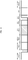
- FIG. 4 illustrates a frame structure of a CAN communication protocol.
- a controller area network is a communication protocol developed by the BOSCH company so as to apply to the automotive industry. Recently, the CAN has been applied in various industrial fields as well as the automotive field and is a serial network communication method having a multi-master message method regulated at the speed of ISO 11898 Specification.
- 'Start of Frame (SOF)' is composed of one dominant bit, marks the start of a message frame and is used for synchronization of all nodes.
- 'SOF' is located at the top of the message frame and has a dominant bit of '0(d)' by default.
- 'Arbitration Field' is composed of an ID having the size of 11 bits or 29 bits and a Remote Transmission Request (RTR) of 1 bit.
- RTR Remote Transmission Request
- 'Arbitration Field' is used to coordinate collisions between messages that occurs when the transmission of the messages from two or more nodes occurs simultaneously.
- a value of the RTR bit is used to determine whether the current message frame is a data frame ('d') or a remote frame ('r'). When the current message frame is a data frame for transmitting data, RTR bit has a value of '0'. On the other hand, when the current message frame is a remote frame requesting data transmission, RTR bit has a '1(r)' value, which is a recessive bit.
- Control Field' is composed of a 2-bit IDentifier Extension (IDE) and a 4-bit Data Length Code (DLC).
- IDE 2-bit IDentifier Extension
- DLC Data Length Code
- 'Data Field' includes data to be transmitted from the data frame.
- 'Data Field' may use up to 8 bytes, and 1 byte is 8 bits. Each byte is transmitted from a most significant bit (MSB).
- MSB most significant bit
- 'Cyclic Redundancy Code (CRC) Field' is composed of a 15-bit CRC sequence generated using bit streams from 'SOF' to 'Data Field' and a CRC Delimiter of one '1 (r)' bit. 'CRC Field' is used to check whether an error is present or absent in a message.
- 'ACK Field' is composed of 1-bit 'ACK Slot' of 1-bit and 1-bit 'ACK Delimiter'.
- the value of 'ACK Slot' is set to '0(d)' at the moment of receiving 'ACK Field' and is continuously transmitted on a bus.
- 'End of Frame (EOF)' is composed of 7 bits having a value of '1(r)' and indicates that the message frame has ended.
- 'Inter frame Space' includes 'Intermission' and 'Bus Idle' and distinguishes the previous or next message frame from the current message frame.
- FIG. 5 is a flowchart illustrating operations of the system controller and the battery controllers, in which the system controller allocates IDs to the battery controllers, according to an embodiment.
- the system controller 110 that is a controller for controlling the electric device 100 of FIG. 1 , may be an integrated controller of the electric device 100 functioning as a master or host.
- the k-th battery controller 310_k that is a battery controller included in the k-th battery pack 300_k that is one of the battery packs 300 of FIG. 1 , may function as a slave with respect to the system controller 100. It is assumed that the k-th battery controller 310_k is included in the k-th battery pack 300_k to be coupled with a k-th station 200_k of FIG. 1 .
- the system controller 110 may operate normally in Operation S101.
- the system controller 110 may already communicate with other battery controllers 310_1 through 310_(k-1) and 310_(k+1) through 310_n except for the k-th battery controller 310_k.
- the system controller 110 may output wake-up signals Wakeup-1 through Wakeup-(k-1) and Wakeup-(k+1) through Wakeup-n corresponding to other battery controllers 310_1 through 310_(k-1) and 310_(k+1) through 310_n in an enabled state ON so as to maintain other battery controllers 310_1 through 310_(k-1) and 310_(k+1) through 310_n in a wake-up state.
- the k-th battery pack 300_k including the k-th battery controller 310_k is before being coupled with the k-th station 200_k, and the k-th battery controller 310_k may be in a shutdown state or sleep state.
- the system controller 110 may maintain the k-th wake-up signal Wakeup-k output to the k-th station 200_k in a disabled state in Operation S102.
- the system controller 110 may determine whether the k-th detection signal Detect-k has been received in Operation S103. Subsequently, the k-th battery pack 300_k may be coupled with the k-th station 200_k. The k-th station 200_k may output a k-th detection signal to the system controller 110. When the system controller 110 receives the k-th detection signal Detect-k, the k-th wake-up signal Wakeup-k may be output in Operation S104. The k-th wake-up signal Wakeup-k may be transmitted to the k-th battery controller 310_k through the k-th station 200_k.
- the k-th battery controller 310_k may determine whether the wake-up signal has been received in Operation S302.
- the k-th battery controller 310_k may be woken up while having a default CAN ID (for example, 0x00) in response to the k-th wake-up signal Wakeup-k output by the system controller 110 in Operation 303.
- the system controller 110 may have a preset master CAN ID (for example, 0xFF), for example. Communication between the system controller 110 having the master CAN ID and the k-th battery controller 310_k having the default CAN ID may be performed in Operations S105 and S304.
- a preset master CAN ID for example, 0xFF
- the system controller 110 may determine whether the k-th battery controller 310_k is in a normal state through communication of Operation S105 in Operation S106. Also, the k-th battery controller 310_k may determine whether the system controller 110 is in a normal state through communication of Operation S304 in Operation 305.
- the system controller 110 may transmit a message for changing the CAN ID to the k-th battery controller 310_k in Operation S107.
- the system controller 110 may transmit a message to change the CAN ID of the k-th battery controller 310_k to 0x0k in correspondence to the position of the k-the battery pack 300_k.
- the k-th battery controller 310_k may receive the CAN ID change message and may change its own CAN ID to a designated CAN ID (for example, 0x0k) according to the message. Subsequently, communication between the system controller 110 having the master CAN ID and the k-th battery controller 310_k having the changed CAN ID (for example, 0x0k) may be performed in Operations S108 and S307.
- the system controller 110 may determine whether communication of Operation S108 has succeeded in Operation S109. Also, the k-th battery controller 310_k may determine whether communication of Operation S307 has succeeded in Operation S308.
- the system controller 110 may operate normally according to a pre-programmed algorithm in Operation S110. Also, the k-th battery controller 310_k may also operate normally according to the pre-programmed algorithm in Operation S309. For example, the system controller 110 may periodically command the k-th battery controller 310_k to report the current state, and the k-th battery controller 310_k may monitor the state of the battery pack 300_k in response to the command and may transmit monitoring data to the system controller 110.
- FIG. 6 schematically illustrates an internal configuration of a station according to an embodiment.
- FIG. 6 the internal configuration of the k-th station 200_k that is one of the stations 200 of FIG. 1 is shown.
- the k-th station 200_k may include a charging circuit 210 for charging the battery cell of the k-th battery pack 300_k to be coupled with the k-th station 200_k.
- the battery system of FIG. 1 including the k-th station 200_k of FIG. 6 may be a battery charging device or battery charging station.
- the k-th station 200_k may include input terminals 211 and 212 for receiving an input power source of the charging circuit 210 and output terminals 213 and 214 for outputting an output voltage of the charging circuit 210.
- An AC voltage or DC voltage may be input through the input terminals 211 and 212.
- the output terminals 213 and 214 may output a charging voltage for charging the battery pack 300_k.
- the k-th station 200_k may include terminals 201a, 202a, and 203a, which are connected to the system controller 110, and terminals 201b, 202b, and 203b, which are connected to the k-th battery controller 310_k of the battery pack 300_k.
- the terminals 201a, 201b, 202a, and 202b may be terminals for transmitting CAN signals received through the CAN bus between the system controller 110 and the k-th battery controller 310_k.
- the terminals 203a and 203b may be terminals for receiving a k-th wake-up signal Wakeup_k output by the system controller 110 and transmitting the k-th wake-up signal Wakeup_k to the k-th battery controller 310_k.
- the k-th station 200_k may further include a sensor 220 for detecting whether the k-th battery pack 300_k has been coupled with the k-th station 200_k.
- the sensor 220 may include a push switch and may generate the detection signal Detect_k as the push switch is pressed when the k-th battery pack 300_k is coupled with the k-th station 200_k.
- the detection signal Detect_k may be transmitted to the system controller 110 through a terminal 204.
- the system controller 110 may output a k-th wake-up signal Wakeup_k and may output an input power source of the charging circuit 210 to the input terminals 211 and 212.
- FIG. 7 schematically illustrates an internal configuration of a battery pack to be coupled with the station of FIG. 6 , according to an embodiment.
- the internal configuration of the k-th battery pack 300_k that is one of the battery packs 300 of FIG. 1 is exemplarily illustrated.
- the k-th battery pack 300_k may include a k-th battery controller 310_k, at least one battery cell 320, and a protection circuit 330.
- the k-th battery pack 300_k may include terminals 301, 302, 303, 323, and 324 to be respectively in contact with terminals 201b, 202b, 203b, 213, and 214 of the k-th station 200_k.
- the k-th battery pack 300_k may be connected to the CAN bus through the terminals 301 and 302 and may receive a wake-up signal Wakeup_k through the terminal 303.
- the k-th battery controller 310_k may be enabled in response to the wake-up signal Wakeup_k received through the terminal 303 and may have a default ID.
- the k-th battery controller 310_k may perform CAN communication with the system controller 110 by using the default ID.
- the k-th battery pack 300_k may discharge or charge the voltage of the battery cell 320 through the terminals 323 and 324.
- the protection circuit 330 may be located between the battery cell 320 and at least one (in the present example, 323) of the terminals 323 and 324.
- the protection circuit 330 may include at least one switch controlled by the battery controller 310_k.
- the protection circuit 330 may include at least one of the charging control switch, the discharging control switch, a main switch, and a pre-charge switch.
- the protection circuit 330 may include a fuse.
- the k-th battery pack 300_k may further include a member 304 for better operating the sensor 220 of the k-th station 200_k.
- the member 304 may be a protrusion for pressing the push switch, and when the sensor 220 is a self-reactive contact sensor, the member 304 may be a magnet.
- FIG. 8 schematically illustrates the internal configuration of a station according to another embodiment.
- the k-th station 200_k' is substantially the same as the k-th station 200_k of FIG. 6 except that the k-th station 200_k' has no terminal 203b and the charging circuit 210' receives the wake-up signal Wakeup_k.
- the k-th station 200_k' of FIG. 8 may include the charging circuit 210' for receiving the wake-up signal Wakeup_k and may not output the wake-up signal Wakeup_k to the battery pack 300_k.
- the charging circuit 210' may operate in response to the wake-up signal Wakeup_k.
- the wake-up signal Wakeup_k to the charging circuit 210' may be an enable signal. That is, the charging circuit 210' may operate when the wake-up signal Wakeup_k is in an enabled state ON, and may stop an operation when the wake-up signal Wakeup_k is in a disabled state OFF.
- FIG. 9 schematically illustrates an internal configuration of a battery pack to be coupled with the station of FIG. 8 , according to an embodiment.
- the k-th battery pack 300_k' may also have no terminal 303 for receiving the wake-up signal Wakeup_k.
- the k-th battery controller 310_k may detect that a charging voltage has been applied to the terminals 323 and 324, and may be woken up.
- the woken-up k-th battery controller 310_k may perform CAN communication with the system controller 110 by using a default ID and may receive an ID allocation command from the system controller 110 so as to change an ID.
- an ID corresponding to a position where the battery pack is mounted is newly allocated to a battery controller of the replaced battery pack.
- the battery controller of the battery pack may perform communication with a system controller.
- the battery system may operate stably, and the position where the battery pack is mounted, and the ID may be matched to each other so that the state of the battery pack may be intuitively displayed to the user.
- connection lines, or connectors shown in the various figures presented are intended to represent exemplary functional relationships and/or physical or logical couplings between the various elements. It should be noted that many alternative or additional functional relationships, physical connections or logical connections may be present in a practical device. Moreover, no item or component is essential to the practice of the present disclosure unless the element is specifically described as "essential” or “critical”.
Landscapes
- Engineering & Computer Science (AREA)
- Power Engineering (AREA)
- Computer Networks & Wireless Communication (AREA)
- Signal Processing (AREA)
- Physics & Mathematics (AREA)
- General Physics & Mathematics (AREA)
- Human Computer Interaction (AREA)
- Charge And Discharge Circuits For Batteries Or The Like (AREA)
- Secondary Cells (AREA)
Description
- One or more embodiments relate to a battery system and a method of allocating a controller area network (CAN) identifier (ID).
- Battery systems refer to various types of systems that supply power to batteries or use power stored in the batteries. A battery charging system that supplies power to batteries, a so-called battery charging station, an electric vehicle or electric bicycle using power stored in the battery, and an energy storage system that uses the batteries as a power storage, may be referred to as a battery system.
- The battery system monitors the internal state of a battery pack for stable operation, and collects data measured by monitoring. In this case, the battery system may employ a master-slave structure for efficient management of the battery pack or data. Battery controllers of the battery packs functioning as a slave transmit detected data to a system controller functioning as a master (or host), and the system controller collects data transmitted by battery controllers.
- Various types of wired/wireless communication are used to exchange information between the system controller and the battery controllers. In controller area network (CAN) communication, which is a typical communication method of wired communication, the system controller and the battery controllers share a CAN bus composed of two signal lines CAN-H and CAN-L. The battery controllers are respectively connected to nodes of the CAN bus, and unique identifiers (hereinafter referred to as 'IDs') are assigned to the battery controllers, and the system controller can collect information transmitted by the battery controllers.
- The battery system may be equipped with modular battery packs. In order to eliminate the inconvenience of taking a considerable amount of time to charge the battery pack, attempts have been made to operate the battery system by replacing the battery pack. In the case of replacing the battery pack in this way, when an ID corresponding to a position where the battery pack is mounted, is allocated to the battery controller, the battery pack corresponding to the ID can be easily identified by the ID alone.
- Since battery packs according to the related art use one ID as a fixed type, it is not possible to exchange information with the system controller through a CAN communication method. Also, even if the battery packs according to the related art use different fixed IDs, in the case of replacing the battery pack, the system controller needs to know the IDs of the battery packs in advance, the IDs of the battery packs and positions where the battery packs are mounted need to be matched to each other and displayed to a user, so that the user can intuitively know the state of the battery pack.
-
EP2725686A1 discloses a multi-BMS identifier allocation system that comprises a master BMS and N slave BMSs (N is an integer greater than or equal to 2) which are connected to a series communication network and a parallel communication network, wherein the master BMS comprises at least two first and second master communication channels which form a communication interface with the series communication network and selectively output a forward or backward enabling signal and allocates unique communication identifiers to the slave BMSs through the parallel communication network, and the first to Nth slave BMSs start enabling in response to the forward or backward enabling signal received through the series communication network, are allocated the identifiers from the master BMS through the parallel communication network, and output an enabling signal to an adjacent slave BMS along a transmission direction of the enabling signal. - The present invention provides a battery system and a method of operating a battery system according to the appended claims. One or more embodiments of the present disclosure relate to a battery system that may operate quickly and stably after a battery pack is replaced, and a method of allocating a new identifier (ID) to the replaced battery pack.
- According to one or more embodiments, a battery system includes a system controller connected to a controller area network (CAN) bus, and a plurality of stations respectively connected to nodes of the CAN bus. When a first station that is one of the plurality of stations detects that a first battery pack has been coupled with the first station, the first station may transmit a first detection signal to the system controller. The system controller may provide a first wake-up signal for waking up the first battery pack to the first station in response to the first detection signal. The first station may wake up a first battery controller of the first battery pack in response to the first wake-up signal. The system controller may transmit, via the CAN bus, a command for allocating a first ID corresponding to the first station to the first battery controller being woken up and having a default ID.
- The battery controller may have the default ID immediately after being woken up, may respond to a message to the default ID transmitted by the system controller, may change the default ID into the first ID in response to the command for allocating the first ID, and may respond to a message to the first ID transmitted by the system controller.
- The first station may transmit the first wake-up signal to the first battery controller, and the first battery controller may be woken up while having the default ID in response to the first wake-up signal.
- The first station may include a charging circuit configured to generate a charging voltage for charging the first battery pack in response to the first wakeup signal and to output the generated charging voltage to the first battery pack. The first battery controller may be woken up in response to the charging voltage.
- The battery system may be a battery pack charging system for respectively charging the plurality of battery packs that are attachable/detachable to/from the plurality of stations.
- The first station may include a sensor unit configured to detect whether the first battery pack has been coupled with the first station, and to generate the first detection signal.
- The battery system may further include a plurality of battery packs respectively coupled with the plurality of stations. Each of the plurality of battery packs may include at least one battery cell, a protection circuit configured to protect the at least one battery cell, and a battery controller which is configured to monitor a state of the at least one battery cell, to control the protection circuit, and connected to the CAN bus through a corresponding station of the plurality of stations.
- The plurality of stations may be arranged according to a preset order, and IDs corresponding to the preset order may be allocated to battery packs coupled with the plurality of stations.
- According to one or more embodiments, a method of allocating a controller area network (CAN) identifier (ID) in a battery system, the battery system including a system controller connected to a CAN bus and a plurality of stations respectively connected to nodes of the CAN bus, the method includes, when a first station that is one of the plurality of stations detects that a first battery pack has been coupled with the first station, transmitting a first detection signal to the system controller, providing a first wake-up signal for waking up the first battery pack to the first station in response to the first detection signal by using the system controller, waking up a first battery controller of the first battery pack in response to the first wake-up signal by using the first station, transmitting a command for allocating a first ID corresponding to the first station to the first battery controller being woken up and having a default ID, via the CAN bus by using the system controller, and changing the default ID into the first ID in response to the command for allocating the first ID by using the first battery controller.
- The waking up of the first battery controller may include generating a charging voltage for charging the first battery pack in response to the first wake-up signal and outputting the generated charging voltage to the first battery pack by using the first station, and waking up the first battery controller in response to the charging voltage.
- Example embodiments will be described in more detail with reference to the accompanying drawings, so that features will be apparent to those skilled in the art.
- The above and other aspects, features, and advantages of certain embodiments of the disclosure will be more apparent from the following description taken in conjunction with the accompanying drawings, in which:
-
FIG. 1 schematically illustrates a battery system according to an embodiment in terms of a power source; -
FIG. 2 schematically illustrates a battery system according to an embodiment in terms of communication; -
FIG. 3 is a block diagram illustrating a communication system having a master-slave structure; -
FIG. 4 illustrates a frame structure of a CAN communication protocol; -
FIG. 5 is a flowchart illustrating operations of a system controller and battery controllers, in which the system controller allocates IDs to the battery controllers, according to an embodiment; -
FIG. 6 schematically illustrates an internal configuration of a station according to an embodiment; -
FIG. 7 schematically illustrates an internal configuration of a battery pack to be coupled with the station ofFIG. 6 , according to an embodiment; -
FIG. 8 schematically illustrates an internal configuration of a station according to another embodiment; and -
FIG. 9 schematically illustrates an internal configuration of a battery pack to be coupled with the station ofFIG. 8 , according to an embodiment. - Reference will now be made in detail to embodiments, examples of which are illustrated in the accompanying drawings, wherein like reference numerals refer to like elements throughout. In this regard, the present embodiments may have different forms and should not be construed as being limited to the descriptions set forth herein. Accordingly, the embodiments are merely described below, by referring to the figures, to explain aspects of the present description. As used herein, the term "and/or" includes any and all combinations of one or more of the associated listed items. Throughout the disclosure, the expression "at least one of a, b or c" indicates only a, only b, only c, both a and b, both a and c, both b and c, all of a, b, and c, or variations thereof.
- Now, example embodiments will be described in more detail with reference to the accompanying drawings. However, the example embodiments can be embodied in many forms and should not be considered as being limited to the embodiments described herein. Rather, these embodiments are provided to make the disclosure of the present disclosure complete, and to fully inform the scope of the present disclosure to those skilled in the art to which the present disclosure pertains.
- The terms used in this application are only used to describe specific embodiments, and are not intended to limit the present disclosure. As used herein, the singular forms "a," "an," and the" are intended to include the plural forms as well, unless the context clearly indicates otherwise. It will be further understood that the terms "comprises" and/or "comprising" used herein specify the presence of stated features or components, but do not preclude the presence or addition of one or more other features or components. It will be understood that although the terms "first," "second," etc. may be used herein to describe various components, these components should not be limited by these terms. These terms are used only to distinguish one component from other components.
-
FIG. 1 schematically illustrates a battery system according to an embodiment in terms of a power source. - Referring to
FIG. 1 , abattery system 1000 may include anelectric device 100 in which a plurality of stations 200_1 through 200_n are mounted. Thebattery system 1000 may further include battery packs 300_1 through 300_n, which may be respectively coupled with the plurality of stations 200_1 through 200_n. - The stations 200_1 through 200_n may be collectively referred to as a station 200, and battery packs 300_1 through 300_n may be collectively referred to as a battery pack 300. The battery pack 300 may include at least one battery cell and a battery controller (which may be referred to as a battery management unit) for managing the at least one battery cell.
- The
battery system 1000 may refer to any system that supplies power to the battery cells of the battery pack 300 or uses the power stored in the battery cells. According to an example, thebattery system 1000 may be a battery charging system (which may be referred to as a battery charging station) for charging the battery cells of the battery packs 300. In this case, theelectric device 100 may include a battery charging device and an integrated controller and may further include a power circuit such as a converter circuit, a user interface device, and the like. Thebattery system 1000 may not include the battery packs 300 but may be coupled with the battery packs 300. - The user may couple the battery packs 300 that need charging with the stations 200 of the
battery charging station 1000, and thebattery charging system 1000 may charge the battery packs 300, and the user may separate the battery packs 300 of which charging is completed, from the stations 200. Thebattery charging system 1000 may include a fare imposing system for imposing a cost corresponding to the charging of the battery packs 300. - Fully-charged battery packs 300 may be coupled with at least part of the stations 200 of the
battery charging station 1000. The user may separate the fully-charged battery packs 300 from thebattery charging station 1000 and may use the fully-charged battery packs 300 according to his/her own purpose. For example, the fully-charged battery packs 300 may be used in an electric transportation device, such as the user's electric bicycle or kickboard. - According to another example, the
battery system 1000 may be an electric transportation system such as an electric vehicle, an electric bicycle, an electric kickboard, or the like, which uses power stored in the battery cells of the battery packs 300. In this case, theelectric device 100 may include a motor device driven using the power stored in the battery cells of the battery packs 300, for example, and an integrated controller and may further include a power circuit such as an inverter circuit or a converter circuit, a user interface device, and the like. Thebattery system 1000 may include the battery packs 300. - According to another example, the
battery system 1000 may be an energy storage system that uses the battery cells of the battery packs 300 as a power storage. In this case, theelectric device 100 may include a converter circuit for supplying a direct current (DC) to the battery packs 300, an inverter circuit for generating an alternating current (AC) from power output from the battery packs 300, and an integrated controller. Thebattery system 1000 may include the battery packs 300. - The station 200 may be a device for interfacing the
electric device 100 and the battery packs 300. The station 200 may electrically connect power terminals of theelectric device 100 to power terminals of the battery packs 300.FIG. 1 illustrates a pair of wires for transmitting power between the stations 200 and the battery packs 300. Wires connected to the stations 200 within theelectric device 100 are differently connected according to the function of thebattery system 1000. Thus, the wires within theelectric device 100 are not shown inFIG. 1 . - Also, the station 200 may provide a communication path between a system controller of the
electric device 100 and a battery controller of the battery pack 300. The communication path may be a CAN bus composed of two signal lines CAN-H and CAN-L. In addition, the station 200 may provide a signal indicating the coupling of the battery pack 300 to the system controller of theelectric device 100 may transmit a control signal from the system controller to the battery controller of the battery pack 300, or may operate the battery controller of the battery pack 300 based on the control signal from the system controller. - The station 200 may further include functional circuits according to the purpose of the
battery system 1000. For example, when thebattery system 1000 is a battery charging system or a battery charging station, the station 200 may include a charging circuit. The charging circuit may be a rectification circuit for generating a DC voltage from an AC voltage, or a converter circuit for generating a DC voltage at a different level from the DC voltage. Furthermore, the station 200 may further include a controller for controlling the charging circuit, and a maintenance capacitor for maintaining a charging voltage. - The battery pack 300 may include at least one battery cell, a protection circuit, and a battery controller. The battery cell may include a rechargeable secondary battery. For example, the battery cell may include a nickel-cadmium battery, a lead acid battery, a nickel metal hydride (NiMH) battery, a lithium ion battery, a lithium polymer battery, and the like. The battery cells may be connected to each other in series, parallel, or a combination of series and parallel, and the number of the battery cells may be determined according to an output voltage required for the battery pack 300.
- The protection circuit that is a circuit for protecting the battery cells may include a charging control switch, a discharging control switch, a fuse, and the like. The battery controller may control the protection circuit by monitoring the state of the battery cells and may transmit the state of the battery cells to the system controller.
-
FIG. 1 illustrates that all of the battery cells 300 are coupled with the stations 200. However, this is just an example, and only some of the battery packs 300 may be coupled with the corresponding stations 200. Any one battery pack (for example, a first battery pack 300_1) may be separated from a first station 200_1, and a new battery pack may be coupled with the first station 200_1 so that the first battery pack 300_1 may be replaced. -
FIG. 2 schematically illustrates a battery system according to an embodiment in terms of communication. - Referring to
FIG. 2 , asystem controller 110, a plurality of stations 200_1 through 200_n, and a plurality of battery controllers 310_1 through 310_n are shown. - The
system controller 110 may be included in theelectric device 100 ofFIG. 1 and may control the overall operation of theelectric device 100. Thesystem controller 110 may be an integrated controller of theelectric device 100. Thesystem controller 110 may include one or more microcontrollers. - The plurality of stations 200_1 through 200_n may transmit detection signals Detect_1 through Detect_n to the
system controller 110 and may transmit wake-up signals Wakeup_1 through Wakeup_n received from thesystem controller 110 to the corresponding battery controllers 310_1 through 310_n. The first station 200_1 may output a first detection signal Detect_1 to thesystem controller 110 and may transmit a first wake-up signal Wakeup_1 received from thesystem controller 110 to the first battery controller 310_1. The stations 200_1 through 200_n, the detection signals Detect_1 through Detect_n, and the wake-up signals Wakeup_1 through Wakeup_n may be collectively referred to as the station 200, a detection signal Detect, and a wake-up signal Wakeup, respectively. - The plurality of battery controllers 310_1 through 310_n may be respectively included in the battery packs 300_1 through 300_n of
FIG. 1 . The plurality of battery controllers 310_1 through 310_n may be collectively referred to as the battery controller 310. The battery controller 310 may monitor the state (voltage, a charging/discharging current, temperature, and the like) of the battery cells of the battery pack 300 and may control the protection circuit. For example, the battery controller 310 may turn off the charging control switch when the voltage of the battery cells exceeds an overvoltage reference value, and may turn off the discharging control switch when the voltage of the battery cells is less than a low voltage reference value, and when the temperature of the battery cells is out of a preset range, the battery controller 300 may turn off charging and/or discharging control switches. - The
system controller 110 may communicate with the battery controllers 310 through the stations 200. Thesystem controller 110 may communicate with the battery controllers 310 through a CAN bus composed of a pair of CAN signal lines CAN_H and CAN_L. Thesystem controller 110 may be connected to the CAN bus, and the stations 200 may be connected to nodes of the CAN bus, respectively. When the battery pack 300 is coupled with the station 310, the battery controller 310 may be connected to the CAN bus through the station 310. CAN communication may be used for a communication protocol between thesystem controller 110 and the battery controllers 310. However, embodiments are not limited thereto, and any communication protocol that transmits data or commands using a bus line, may be used. - When the battery pack 300 is coupled with the corresponding station 200, the station 200 may detect that the battery pack 300 has been coupled with the station 200, and may output the detection signal Detect to the
system controller 110. The station 200 may include a sensor unit for detecting that the battery pack 300 has been coupled with the station 200. For example, the sensor unit may be a push switch the state of which is changed by the connection of the battery pack 300. According to another example, the sensor unit may be a proximity sensor for detecting that the battery pack 300 is located at a certain position. - The
system controller 110 may output the wake-up signal Wakeup for waking up the battery pack 300 in response to the detection signal output by the station 200. When the battery pack 300 is coupled with the station 200, the battery controller 310 of the battery pack 300 may be in a shutdown state. The station 200 may wake up the battery controller 310 of the battery pack 300 in response to the wake-up signal Wakeup output from thesystem controller 100. - For example, when it is assumed that a new first battery pack 300_1 is coupled with the first station 200_1, the first battery controller 310_1 of the first battery pack 300_1 before the first battery pack 300_1 is coupled with the first station 200_1, may be in a shutdown state. When the first battery pack 300_1 is coupled with the first station 200_1, the first station 200_1 may detect that the first battery pack 300_1 has been coupled with the first station 200_1, and may output the first detection signal Detect_1 to the
system controller 110. Thesystem controller 110 may receive the first detection signal Detect_1 and may output the first wake-up signal Wakeup_1 in response to the first detection signal Detect_1. The first wake-up signal Wakeup_1 may be a signal for waking up the first battery controller 310_1. According to an example, the first station 200_1 may transmit the first wake-up signal Wakeup_1 to the first battery controller 310_1 so as to wake up the first battery controller 310_1. - The CAN bus may include a pair of CAN signal lines CAN_H and CAN_L. The CAN bus may be connected to the
system controller 110 and may be connected to the battery controllers 310 through the stations 200. Communication between thesystem controller 110 and thebattery controllers 210 through the CAN bus will be described with reference toFIGS. 3 and4 . -
FIG. 3 is a block diagram illustrating a communication system having a master-slave structure. - Referring to
FIG. 3 , the communication system may include thesystem controller 110, the plurality of battery controllers 310_1 through 310_n, and aCAN bus 400. - The
system controller 110 may transmit a frame signal Cs including commands to theCAN bus 400. The first through n-th battery controllers 310_1 through 310_n may receive the frame signal Cs and may perform operations corresponding to the commands included in the frame signal Cs. The frame signal Cs may include an ID allocation command and may be transmitted to the battery controllers 310_1 through 310_n of the battery packs 300_1 through 300_n that have been newly replaced using a default ID. The battery controllers 310_1 through 310_n may have the default ID until the ID allocation command is received. The default ID that is a preset ID may be 0x00, for example. - The frame signal Cs may include a command for controlling the battery controllers 310_1 through 310_n and may be transmitted to specific battery controllers 310_1 through 310_n using IDs allocated through the ID allocation command. IDs corresponding to positions of the battery packs 300_1 through 300_n may be allocated to the battery controllers 310_1 through 310_n. For example, an ID of 0x01 corresponding to the position of the first battery pack 300_1 may be allocated to the first battery controller 310_1 of the first battery pack 300_1. An ID of 0x0k corresponding to the position of a k-th battery pack 300_k may be allocated to a k-th battery controller 310_k of the k-th battery pack 300_k. An ID of 0x20 corresponding to the position of a twentieth battery pack 300_20 may be allocated to a twentieth battery controller 310_20 of the twentieth battery pack 300_20.
- Each of the first through n-th battery controllers 310_1 through 310_n may transmit frame signals D1 through Dn including data to the
CAN bus 400. In this case, the first through n-th battery controllers 310_1 through 310_n may transmit the frame signals D1 through Dm including unique IDs allocated to the first through n-th battery controllers 310_1 through 310_n to thesystem controller 110 so as to prevent data collision. Thesystem controller 110 may receive the transmitted frame signals D1 through Dn and may perform processing according to a pre-designed algorithm. - The frame signals D1 through Dn may be transmitted to the battery controllers 310_1 through 310_n in addition to the
system controller 110. For example, the frame signal D1 transmitted by the first battery controller 310_1 may be transmitted to the remaining battery controllers 310_1 through 310_n in a broadcast manner. - A method of transmitting data in a communication system having the master-slave structure described above will be described in detail.
-
FIG. 4 illustrates a frame structure of a CAN communication protocol. - A controller area network (CAN) is a communication protocol developed by the BOSCH company so as to apply to the automotive industry. Recently, the CAN has been applied in various industrial fields as well as the automotive field and is a serial network communication method having a multi-master message method regulated at the speed of ISO 11898 Specification.
- 'Start of Frame (SOF)' is composed of one dominant bit, marks the start of a message frame and is used for synchronization of all nodes. 'SOF' is located at the top of the message frame and has a dominant bit of '0(d)' by default.
- 'Arbitration Field' is composed of an ID having the size of 11 bits or 29 bits and a Remote Transmission Request (RTR) of 1 bit. 'Arbitration Field' is used to coordinate collisions between messages that occurs when the transmission of the messages from two or more nodes occurs simultaneously. A value of the RTR bit is used to determine whether the current message frame is a data frame ('d') or a remote frame ('r'). When the current message frame is a data frame for transmitting data, RTR bit has a value of '0'. On the other hand, when the current message frame is a remote frame requesting data transmission, RTR bit has a '1(r)' value, which is a recessive bit.
- 'Control Field' is composed of a 2-bit IDentifier Extension (IDE) and a 4-bit Data Length Code (DLC). The 2-bit IDE is a reserved region, and the 4-bit DLC represents the number of bytes of a data field.
- 'Data Field' includes data to be transmitted from the data frame. 'Data Field' may use up to 8 bytes, and 1 byte is 8 bits. Each byte is transmitted from a most significant bit (MSB).
- 'Cyclic Redundancy Code (CRC) Field' is composed of a 15-bit CRC sequence generated using bit streams from 'SOF' to 'Data Field' and a CRC Delimiter of one '1 (r)' bit. 'CRC Field' is used to check whether an error is present or absent in a message.
- 'ACK Field' is composed of 1-bit 'ACK Slot' of 1-bit and 1-bit 'ACK Delimiter'. When a correct message is received from an arbitrary node, the value of 'ACK Slot' is set to '0(d)' at the moment of receiving 'ACK Field' and is continuously transmitted on a bus.
- 'End of Frame (EOF)' is composed of 7 bits having a value of '1(r)' and indicates that the message frame has ended.
- 'Inter frame Space' includes 'Intermission' and 'Bus Idle' and distinguishes the previous or next message frame from the current message frame.
- Hereinafter, a method of allocating IDs corresponding to positions of battery packs to battery controllers by using a system controller in a communication system including the system controller functioning as a master (or a host) and the battery controllers functioning as a slave will be described.
-
FIG. 5 is a flowchart illustrating operations of the system controller and the battery controllers, in which the system controller allocates IDs to the battery controllers, according to an embodiment. - Referring to
FIG. 5 , thesystem controller 110 and the k-th battery controller 310_k are exemplarily illustrated. Thesystem controller 110 that is a controller for controlling theelectric device 100 ofFIG. 1 , may be an integrated controller of theelectric device 100 functioning as a master or host. The k-th battery controller 310_k that is a battery controller included in the k-th battery pack 300_k that is one of the battery packs 300 ofFIG. 1 , may function as a slave with respect to thesystem controller 100. It is assumed that the k-th battery controller 310_k is included in the k-th battery pack 300_k to be coupled with a k-th station 200_k ofFIG. 1 . - The
system controller 110 may operate normally in Operation S101. Thesystem controller 110 may already communicate with other battery controllers 310_1 through 310_(k-1) and 310_(k+1) through 310_n except for the k-th battery controller 310_k. Thesystem controller 110 may output wake-up signals Wakeup-1 through Wakeup-(k-1) and Wakeup-(k+1) through Wakeup-n corresponding to other battery controllers 310_1 through 310_(k-1) and 310_(k+1) through 310_n in an enabled state ON so as to maintain other battery controllers 310_1 through 310_(k-1) and 310_(k+1) through 310_n in a wake-up state. - The k-th battery pack 300_k including the k-th battery controller 310_k is before being coupled with the k-th station 200_k, and the k-th battery controller 310_k may be in a shutdown state or sleep state. The
system controller 110 may maintain the k-th wake-up signal Wakeup-k output to the k-th station 200_k in a disabled state in Operation S102. - The
system controller 110 may determine whether the k-th detection signal Detect-k has been received in Operation S103. Subsequently, the k-th battery pack 300_k may be coupled with the k-th station 200_k. The k-th station 200_k may output a k-th detection signal to thesystem controller 110. When thesystem controller 110 receives the k-th detection signal Detect-k, the k-th wake-up signal Wakeup-k may be output in Operation S104. The k-th wake-up signal Wakeup-k may be transmitted to the k-th battery controller 310_k through the k-th station 200_k. - The k-th battery controller 310_k may determine whether the wake-up signal has been received in Operation S302. The k-th battery controller 310_k may be woken up while having a default CAN ID (for example, 0x00) in response to the k-th wake-up signal Wakeup-k output by the
system controller 110 inOperation 303. - The
system controller 110 may have a preset master CAN ID (for example, 0xFF), for example. Communication between thesystem controller 110 having the master CAN ID and the k-th battery controller 310_k having the default CAN ID may be performed in Operations S105 and S304. - The
system controller 110 may determine whether the k-th battery controller 310_k is in a normal state through communication of Operation S105 in Operation S106. Also, the k-th battery controller 310_k may determine whether thesystem controller 110 is in a normal state through communication of Operation S304 inOperation 305. - When it is determined that the
system controller 110 determines that the k-th battery controller 310_k is in a normal state, thesystem controller 110 may transmit a message for changing the CAN ID to the k-th battery controller 310_k in Operation S107. Thesystem controller 110 may transmit a message to change the CAN ID of the k-th battery controller 310_k to 0x0k in correspondence to the position of the k-the battery pack 300_k. The k-th battery controller 310_k may receive the CAN ID change message and may change its own CAN ID to a designated CAN ID (for example, 0x0k) according to the message. Subsequently, communication between thesystem controller 110 having the master CAN ID and the k-th battery controller 310_k having the changed CAN ID (for example, 0x0k) may be performed in Operations S108 and S307. - The
system controller 110 may determine whether communication of Operation S108 has succeeded in Operation S109. Also, the k-th battery controller 310_k may determine whether communication of Operation S307 has succeeded in Operation S308. - When communication between the
system controller 110 having the master CAN ID and the k-th battery controller 310_k having the changed CAN ID (for example, 0×0k) has succeeded, thesystem controller 110 may operate normally according to a pre-programmed algorithm in Operation S110. Also, the k-th battery controller 310_k may also operate normally according to the pre-programmed algorithm in Operation S309. For example, thesystem controller 110 may periodically command the k-th battery controller 310_k to report the current state, and the k-th battery controller 310_k may monitor the state of the battery pack 300_k in response to the command and may transmit monitoring data to thesystem controller 110. -
FIG. 6 schematically illustrates an internal configuration of a station according to an embodiment. - Referring to
FIG. 6 , the internal configuration of the k-th station 200_k that is one of the stations 200 ofFIG. 1 is shown. - The k-th station 200_k may include a
charging circuit 210 for charging the battery cell of the k-th battery pack 300_k to be coupled with the k-th station 200_k. The battery system ofFIG. 1 including the k-th station 200_k ofFIG. 6 may be a battery charging device or battery charging station. - The k-th station 200_k may include
input terminals circuit 210 andoutput terminals circuit 210. An AC voltage or DC voltage may be input through theinput terminals output terminals - The k-th station 200_k may include
terminals system controller 110, andterminals terminals system controller 110 and the k-th battery controller 310_k. Theterminals system controller 110 and transmitting the k-th wake-up signal Wakeup_k to the k-th battery controller 310_k. - The k-th station 200_k may further include a
sensor 220 for detecting whether the k-th battery pack 300_k has been coupled with the k-th station 200_k. For example, thesensor 220 may include a push switch and may generate the detection signal Detect_k as the push switch is pressed when the k-th battery pack 300_k is coupled with the k-th station 200_k. The detection signal Detect_k may be transmitted to thesystem controller 110 through a terminal 204. - When the
system controller 110 receives the detection signal Detect_k through the terminal 204, thesystem controller 110 may output a k-th wake-up signal Wakeup_k and may output an input power source of the chargingcircuit 210 to theinput terminals -
FIG. 7 schematically illustrates an internal configuration of a battery pack to be coupled with the station ofFIG. 6 , according to an embodiment. - Referring to
FIG. 7 , the internal configuration of the k-th battery pack 300_k that is one of the battery packs 300 ofFIG. 1 is exemplarily illustrated. - The k-th battery pack 300_k may include a k-th battery controller 310_k, at least one
battery cell 320, and aprotection circuit 330. - The k-th battery pack 300_k may include
terminals terminals terminals system controller 110 by using the default ID. - The k-th battery pack 300_k may discharge or charge the voltage of the
battery cell 320 through theterminals protection circuit 330 may be located between thebattery cell 320 and at least one (in the present example, 323) of theterminals protection circuit 330 may include at least one switch controlled by the battery controller 310_k. Theprotection circuit 330 may include at least one of the charging control switch, the discharging control switch, a main switch, and a pre-charge switch. Theprotection circuit 330 may include a fuse. - The k-th battery pack 300_k may further include a
member 304 for better operating thesensor 220 of the k-th station 200_k. When thesensor 220 is a push switch, themember 304 may be a protrusion for pressing the push switch, and when thesensor 220 is a self-reactive contact sensor, themember 304 may be a magnet. -
FIG. 8 schematically illustrates the internal configuration of a station according to another embodiment. - Referring to
FIG. 8 , the k-th station 200_k' is substantially the same as the k-th station 200_k ofFIG. 6 except that the k-th station 200_k' has no terminal 203b and the charging circuit 210' receives the wake-up signal Wakeup_k. - The k-th station 200_k' of
FIG. 8 may include the charging circuit 210' for receiving the wake-up signal Wakeup_k and may not output the wake-up signal Wakeup_k to the battery pack 300_k. - The charging circuit 210' may operate in response to the wake-up signal Wakeup_k. The wake-up signal Wakeup_k to the charging circuit 210' may be an enable signal. That is, the charging circuit 210' may operate when the wake-up signal Wakeup_k is in an enabled state ON, and may stop an operation when the wake-up signal Wakeup_k is in a disabled state OFF.
-
FIG. 9 schematically illustrates an internal configuration of a battery pack to be coupled with the station ofFIG. 8 , according to an embodiment. - Referring to
FIG. 9 , the k-th battery pack 300_k' may also have no terminal 303 for receiving the wake-up signal Wakeup_k. The k-th battery controller 310_k may detect that a charging voltage has been applied to theterminals system controller 110 by using a default ID and may receive an ID allocation command from thesystem controller 110 so as to change an ID. - In a battery system according to the spirit of the present disclosure, even when a battery pack is replaced, an ID corresponding to a position where the battery pack is mounted, is newly allocated to a battery controller of the replaced battery pack. Thus, the battery controller of the battery pack may perform communication with a system controller. Thus, the battery system may operate stably, and the position where the battery pack is mounted, and the ID may be matched to each other so that the state of the battery pack may be intuitively displayed to the user.
- Various embodiments of the present disclosure are not intended to otherwise limit the scope of the present disclosure in any way. For the sake of brevity, conventional electronics, control systems, software development and other functional aspects of the systems (and components of the individual operating components of the systems) may not be described in detail. Furthermore, the connection lines, or connectors shown in the various figures presented are intended to represent exemplary functional relationships and/or physical or logical couplings between the various elements. It should be noted that many alternative or additional functional relationships, physical connections or logical connections may be present in a practical device. Moreover, no item or component is essential to the practice of the present disclosure unless the element is specifically described as "essential" or "critical".
- The use of the terms "a" and "an" and "the" and similar referents in the context of describing the present disclosure (especially in the context of the following claims) are to be construed to cover both the singular and the plural. Furthermore, recitation of ranges of values herein are merely intended to serve as a shorthand method of referring individually to each separate value falling within the range, unless otherwise indicated herein, and each separate value is incorporated into the specification as if it were individually recited herein. Finally, the steps of all methods described herein can be performed in any suitable order unless otherwise indicated herein or otherwise clearly contradicted by context. The present disclosure is not necessarily limited according to the description order of the steps. The use of any and all examples, or exemplary language (e.g., "such as") provided herein, is intended merely to better illuminate the invention and does not pose a limitation on the scope of the invention unless otherwise claimed. Numerous modifications and adaptations will be readily apparent to those skilled in this art without departing from the scope of the present invention.
- It should be understood that embodiments described herein should be considered in a descriptive sense only and not for purposes of limitation. Descriptions of features or aspects within each embodiment should typically be considered as available for other similar features or aspects in other embodiments. While one or more embodiments have been described with reference to the figures, it will be understood by those of ordinary skill in the art that various changes in form and details may be made therein without departing from the scope of the invention as defined by the following claims.
Claims (10)
- A battery system (1000) comprising:a system controller (110) connected to a controller area network, CAN, bus; anda plurality of stations (200) respectively connected to nodes of the CAN bus, wherein,a first station (200_1) of the plurality of stations is configured to detect that a first battery pack (300_1) has been coupled with the first station (200_1) and transmit a first detection signal (Detect_1) to the system controller (110),wherein the system controller (110) is configured to provide a first wake-up signal (Wakeup_1) for waking up the first battery pack (300_1) to the first station (200_1), in response to the first detection signal (Detect_1),wherein the first station (200_1) is configured to wake up a first battery controller (310_1) of the first battery pack (300_1) in response to the first wake-up signal (Wakeup_1), andwherein the system controller (110) is configured to transmit a command for allocating a first identifier, ID, corresponding to the first station (200_1) to the first battery controller (310_1) having a default ID via the CAN bus.
- The battery system (1000) of claim 1, wherein the battery controller (310_1) is configured to: have the default ID immediately after being woken up; respond to a message to the default ID transmitted by the system controller (110); change the default ID into the first ID in response to the command for allocating the first ID; and, transmit a response message using the first ID transmitted by the system controller (110).
- The battery system (1000) of either of claims 1 or 2, wherein the first station (200_1) is configured to transmit the first wake-up signal (Wakeup_1) to the first battery controller (310_1), and the first battery controller (310_1) is configured to be woken up while having the default ID in response to the first wake-up signal (Wakeup_1).
- The battery system (1000) of any preceding claim, wherein the first station (200_1) is configured to generate a charging voltage for charging the first battery pack (300_1) in response to the first wake-up signal (Wakeup_1) and output the generated charging voltage to the first battery pack (300_1), and
the first battery controller (310_1) is configured to be woken up in response to receiving the charging voltage. - The battery system (1000) of claim 4, wherein the battery system is a battery pack charging system for respectively charging the plurality of battery packs that are attachable/detachable to/from the plurality of stations (200).
- The battery system (1000) of any preceding claim, wherein the first station (200_1) comprises a sensor unit (220) configured to detect whether the first battery pack (300_1) has been coupled with the first station (200_1) and to generate the first detection signal (Detect_1).
- The battery system (1000) of any preceding claim, further comprising a plurality of battery packs (300) respectively coupled with the plurality of stations (200), wherein
each of the plurality of battery packs (300_k) comprises:at least one battery cell (320);a protection circuit (330) configured to protect the at least one battery cell (320); anda battery controller (310_k) which is configured to monitor a state of the at least one battery cell (320) to control the protection circuit (330), and connected to the CAN bus through a corresponding station (200_k) of the plurality of stations. - The battery system (1000) of any preceding claim, wherein the plurality of stations (200) are arranged in a preset order, and IDs corresponding to the preset order are allocated to battery packs (300) coupled with the plurality of stations (200).
- A method of allocating a controller area network, CAN, identifier, ID, in a battery system (1000),
the battery system (1000) comprising a system controller (110) connected to the CAN bus and a plurality of stations (200) respectively connected to nodes of the CAN bus, the method comprising:when a first station (200_1) that is one of the plurality of stations (200) detects that a first battery pack (300_1) has been coupled with the first station (200_1), transmitting a first detection signal (Detect_1) to the system controller (110);providing a first wake-up signal (Wakeup_1) for waking up the first battery pack (300_1) to the first station (200_1), in response to the first detection signal (Detect_1), by using the system controller (110);waking up a first battery controller (310_1) of the first battery pack (300_1) in response to the first wake-up signal (Wakeup_1), by using the first station (200_1);transmitting a command for allocating a first ID corresponding to the first station (200_1) to the first battery controller (310_1) being woken up and having a default ID, via the CAN bus, by using the system controller (110); andchanging the default ID into the first ID in response to the command for allocating the first ID, by using the first battery controller (310_1). - The method of claim 9, wherein the waking up of the first battery controller (310_1) comprises:generating a charging voltage for charging the first battery pack (300-1) in response to the first wake-up signal (Wakeup_1) and outputting the generated charging voltage to the first battery pack (310_1), by using the first station (200_1); andwaking up the first battery controller (310_1) in response to the charging voltage.
Priority Applications (1)
| Application Number | Priority Date | Filing Date | Title |
|---|---|---|---|
| PL20207555T PL3823129T3 (en) | 2019-11-13 | 2020-11-13 | Battery system, and method of allocating can id |
Applications Claiming Priority (1)
| Application Number | Priority Date | Filing Date | Title |
|---|---|---|---|
| KR1020190145402A KR20210058206A (en) | 2019-11-13 | 2019-11-13 | Battery system and method of allocating CAN ID |
Publications (2)
| Publication Number | Publication Date |
|---|---|
| EP3823129A1 EP3823129A1 (en) | 2021-05-19 |
| EP3823129B1 true EP3823129B1 (en) | 2022-04-06 |
Family
ID=73448937
Family Applications (1)
| Application Number | Title | Priority Date | Filing Date |
|---|---|---|---|
| EP20207555.2A Active EP3823129B1 (en) | 2019-11-13 | 2020-11-13 | Battery system, and method of allocating can id |
Country Status (7)
| Country | Link |
|---|---|
| US (1) | US11495975B2 (en) |
| EP (1) | EP3823129B1 (en) |
| KR (1) | KR20210058206A (en) |
| CN (1) | CN112803584B (en) |
| HU (1) | HUE059224T2 (en) |
| PL (1) | PL3823129T3 (en) |
| TW (1) | TWI766436B (en) |
Cited By (1)
| Publication number | Priority date | Publication date | Assignee | Title |
|---|---|---|---|---|
| EP4329139A1 (en) * | 2022-07-13 | 2024-02-28 | STILL GmbH | Device for controlling a plurality of battery charging devices |
Families Citing this family (3)
| Publication number | Priority date | Publication date | Assignee | Title |
|---|---|---|---|---|
| KR20210103299A (en) * | 2020-02-13 | 2021-08-23 | 주식회사 엘지에너지솔루션 | Battery control system, battery pack, electric vehicle, and control method for the battery control system |
| CN114142567A (en) * | 2021-12-06 | 2022-03-04 | 珠海冠宇动力电源有限公司 | Battery management circuit and battery device |
| WO2024090776A1 (en) * | 2022-10-26 | 2024-05-02 | 주식회사 엘지에너지솔루션 | Battery manufacturing method and battery manufacturing system |
Family Cites Families (10)
| Publication number | Priority date | Publication date | Assignee | Title |
|---|---|---|---|---|
| KR101561885B1 (en) | 2011-11-25 | 2015-10-21 | 주식회사 엘지화학 | System and method for identifier allowcation of multi-bms |
| KR101539689B1 (en) | 2012-02-20 | 2015-07-27 | 주식회사 엘지화학 | System and method for identifier allowcation of multi-bms |
| KR101433478B1 (en) | 2012-12-17 | 2014-09-18 | 넥스콘 테크놀러지 주식회사 | A Method of Auto CAN ID Setting for Energy Storage System Slave Battery Management System |
| KR102210890B1 (en) | 2013-06-05 | 2021-02-02 | 삼성에스디아이 주식회사 | Battery management system, and method of managing the same |
| KR101632350B1 (en) | 2013-09-09 | 2016-06-21 | 주식회사 엘지화학 | System and method for communication identifier allowcation of multi-bms |
| US10084329B2 (en) | 2014-02-28 | 2018-09-25 | Nrg Energy, Inc. | Power pack vending apparatus, system, and method of use for charging power packs with biased locking arrangement |
| KR102273646B1 (en) * | 2014-10-27 | 2021-07-06 | 삼성에스디아이 주식회사 | Energy storage system and id installing mathod to battery tray of the same |
| CN105186610B (en) | 2015-09-07 | 2017-10-03 | 湖北工业大学 | A kind of battery management system and method based on network communication of wireless sensor |
| KR102101909B1 (en) | 2015-11-02 | 2020-04-17 | 주식회사 엘지화학 | Apparatus and method for battery id assignment |
| TWI581542B (en) | 2016-03-01 | 2017-05-01 | 財團法人工業技術研究院 | Battery management system and battery system using the same |
-
2019
- 2019-11-13 KR KR1020190145402A patent/KR20210058206A/en unknown
-
2020
- 2020-11-10 US US17/094,220 patent/US11495975B2/en active Active
- 2020-11-13 HU HUE20207555A patent/HUE059224T2/en unknown
- 2020-11-13 TW TW109139666A patent/TWI766436B/en active
- 2020-11-13 EP EP20207555.2A patent/EP3823129B1/en active Active
- 2020-11-13 CN CN202011268115.0A patent/CN112803584B/en active Active
- 2020-11-13 PL PL20207555T patent/PL3823129T3/en unknown
Cited By (1)
| Publication number | Priority date | Publication date | Assignee | Title |
|---|---|---|---|---|
| EP4329139A1 (en) * | 2022-07-13 | 2024-02-28 | STILL GmbH | Device for controlling a plurality of battery charging devices |
Also Published As
| Publication number | Publication date |
|---|---|
| KR20210058206A (en) | 2021-05-24 |
| EP3823129A1 (en) | 2021-05-19 |
| CN112803584A (en) | 2021-05-14 |
| HUE059224T2 (en) | 2022-10-28 |
| CN112803584B (en) | 2024-03-22 |
| PL3823129T3 (en) | 2022-06-20 |
| US20210143648A1 (en) | 2021-05-13 |
| TWI766436B (en) | 2022-06-01 |
| TW202119225A (en) | 2021-05-16 |
| US11495975B2 (en) | 2022-11-08 |
Similar Documents
| Publication | Publication Date | Title |
|---|---|---|
| EP3823129B1 (en) | Battery system, and method of allocating can id | |
| US8933671B2 (en) | System and method for allocating identifier to multi-BMS | |
| CN110462915B (en) | Wireless battery management device and battery pack including the same | |
| US9209641B2 (en) | Communication method, communication system, and energy storage system including the same | |
| US9812891B2 (en) | Method for transferring wireless power | |
| KR102210890B1 (en) | Battery management system, and method of managing the same | |
| US9088052B2 (en) | Battery multi-series system and communication method thereof | |
| JP2020504421A (en) | Battery management unit and battery pack including the same | |
| KR101561885B1 (en) | System and method for identifier allowcation of multi-bms | |
| EP3624297B1 (en) | Battery management system | |
| US20080059816A1 (en) | Power supply capable of receiving digital communications from electronic devices | |
| CN106657427B (en) | Battery module address distribution system and method | |
| KR20130053885A (en) | Battery management system and battery pack protection apparatus including the same | |
| US20120106663A1 (en) | Method for transmitting data | |
| CN105208518A (en) | Wireless router device, wireless router system and communication method | |
| CN110871703A (en) | Alternating current charging interface of electric vehicle and charging and discharging method thereof | |
| EP2988190B1 (en) | Communication terminal for constructing daisy chain communication network without distinction between input connector and output connector | |
| KR20200031931A (en) | System and method for recognition of BMS | |
| KR20200046619A (en) | Battery management device that does not require external power source with battery terminal fixing structure | |
| KR20200096732A (en) | Control device for vehicle, vehicle, and control method of vehicle | |
| CN220615549U (en) | Main control battery management system and electric automobile | |
| WO2023125012A1 (en) | Battery management system and battery pack | |
| CN116691441A (en) | Main control battery management system and control method thereof | |
| JP2023067854A (en) | Reduced power wireless battery management system | |
| KR20240021668A (en) | METHOD FOR SCHEDULING Wireless charging OF AN ELECTRIC VEHICLE for multiple wireless charging stations and multiple user environments in a wireless power transmission system and APPARATUS supporting the same |
Legal Events
| Date | Code | Title | Description |
|---|---|---|---|
| PUAI | Public reference made under article 153(3) epc to a published international application that has entered the european phase |
Free format text: ORIGINAL CODE: 0009012 |
|
| STAA | Information on the status of an ep patent application or granted ep patent |
Free format text: STATUS: REQUEST FOR EXAMINATION WAS MADE |
|
| 17P | Request for examination filed |
Effective date: 20201113 |
|
| AK | Designated contracting states |
Kind code of ref document: A1 Designated state(s): AL AT BE BG CH CY CZ DE DK EE ES FI FR GB GR HR HU IE IS IT LI LT LU LV MC MK MT NL NO PL PT RO RS SE SI SK SM TR |
|
| GRAP | Despatch of communication of intention to grant a patent |
Free format text: ORIGINAL CODE: EPIDOSNIGR1 |
|
| STAA | Information on the status of an ep patent application or granted ep patent |
Free format text: STATUS: GRANT OF PATENT IS INTENDED |
|
| INTG | Intention to grant announced |
Effective date: 20211025 |
|
| GRAS | Grant fee paid |
Free format text: ORIGINAL CODE: EPIDOSNIGR3 |
|
| GRAA | (expected) grant |
Free format text: ORIGINAL CODE: 0009210 |
|
| STAA | Information on the status of an ep patent application or granted ep patent |
Free format text: STATUS: THE PATENT HAS BEEN GRANTED |
|
| AK | Designated contracting states |
Kind code of ref document: B1 Designated state(s): AL AT BE BG CH CY CZ DE DK EE ES FI FR GB GR HR HU IE IS IT LI LT LU LV MC MK MT NL NO PL PT RO RS SE SI SK SM TR |
|
| REG | Reference to a national code |
Ref country code: GB Ref legal event code: FG4D |
|
| REG | Reference to a national code |
Ref country code: CH Ref legal event code: EP |
|
| REG | Reference to a national code |
Ref country code: AT Ref legal event code: REF Ref document number: 1482296 Country of ref document: AT Kind code of ref document: T Effective date: 20220415 |
|
| REG | Reference to a national code |
Ref country code: DE Ref legal event code: R096 Ref document number: 602020002572 Country of ref document: DE |
|
| REG | Reference to a national code |
Ref country code: IE Ref legal event code: FG4D |
|
| REG | Reference to a national code |
Ref country code: SE Ref legal event code: TRGR |
|
| REG | Reference to a national code |
Ref country code: LT Ref legal event code: MG9D |
|
| REG | Reference to a national code |
Ref country code: NL Ref legal event code: MP Effective date: 20220406 |
|
| PG25 | Lapsed in a contracting state [announced via postgrant information from national office to epo] |
Ref country code: NL Free format text: LAPSE BECAUSE OF FAILURE TO SUBMIT A TRANSLATION OF THE DESCRIPTION OR TO PAY THE FEE WITHIN THE PRESCRIBED TIME-LIMIT Effective date: 20220406 |
|
| REG | Reference to a national code |
Ref country code: HU Ref legal event code: AG4A Ref document number: E059224 Country of ref document: HU |
|
| PG25 | Lapsed in a contracting state [announced via postgrant information from national office to epo] |
Ref country code: PT Free format text: LAPSE BECAUSE OF FAILURE TO SUBMIT A TRANSLATION OF THE DESCRIPTION OR TO PAY THE FEE WITHIN THE PRESCRIBED TIME-LIMIT Effective date: 20220808 Ref country code: NO Free format text: LAPSE BECAUSE OF FAILURE TO SUBMIT A TRANSLATION OF THE DESCRIPTION OR TO PAY THE FEE WITHIN THE PRESCRIBED TIME-LIMIT Effective date: 20220706 Ref country code: LT Free format text: LAPSE BECAUSE OF FAILURE TO SUBMIT A TRANSLATION OF THE DESCRIPTION OR TO PAY THE FEE WITHIN THE PRESCRIBED TIME-LIMIT Effective date: 20220406 Ref country code: HR Free format text: LAPSE BECAUSE OF FAILURE TO SUBMIT A TRANSLATION OF THE DESCRIPTION OR TO PAY THE FEE WITHIN THE PRESCRIBED TIME-LIMIT Effective date: 20220406 Ref country code: GR Free format text: LAPSE BECAUSE OF FAILURE TO SUBMIT A TRANSLATION OF THE DESCRIPTION OR TO PAY THE FEE WITHIN THE PRESCRIBED TIME-LIMIT Effective date: 20220707 Ref country code: FI Free format text: LAPSE BECAUSE OF FAILURE TO SUBMIT A TRANSLATION OF THE DESCRIPTION OR TO PAY THE FEE WITHIN THE PRESCRIBED TIME-LIMIT Effective date: 20220406 Ref country code: ES Free format text: LAPSE BECAUSE OF FAILURE TO SUBMIT A TRANSLATION OF THE DESCRIPTION OR TO PAY THE FEE WITHIN THE PRESCRIBED TIME-LIMIT Effective date: 20220406 Ref country code: BG Free format text: LAPSE BECAUSE OF FAILURE TO SUBMIT A TRANSLATION OF THE DESCRIPTION OR TO PAY THE FEE WITHIN THE PRESCRIBED TIME-LIMIT Effective date: 20220706 |
|
| PG25 | Lapsed in a contracting state [announced via postgrant information from national office to epo] |
Ref country code: RS Free format text: LAPSE BECAUSE OF FAILURE TO SUBMIT A TRANSLATION OF THE DESCRIPTION OR TO PAY THE FEE WITHIN THE PRESCRIBED TIME-LIMIT Effective date: 20220406 Ref country code: LV Free format text: LAPSE BECAUSE OF FAILURE TO SUBMIT A TRANSLATION OF THE DESCRIPTION OR TO PAY THE FEE WITHIN THE PRESCRIBED TIME-LIMIT Effective date: 20220406 Ref country code: IS Free format text: LAPSE BECAUSE OF FAILURE TO SUBMIT A TRANSLATION OF THE DESCRIPTION OR TO PAY THE FEE WITHIN THE PRESCRIBED TIME-LIMIT Effective date: 20220806 |
|
| REG | Reference to a national code |
Ref country code: DE Ref legal event code: R097 Ref document number: 602020002572 Country of ref document: DE |
|
| PG25 | Lapsed in a contracting state [announced via postgrant information from national office to epo] |
Ref country code: SM Free format text: LAPSE BECAUSE OF FAILURE TO SUBMIT A TRANSLATION OF THE DESCRIPTION OR TO PAY THE FEE WITHIN THE PRESCRIBED TIME-LIMIT Effective date: 20220406 Ref country code: SK Free format text: LAPSE BECAUSE OF FAILURE TO SUBMIT A TRANSLATION OF THE DESCRIPTION OR TO PAY THE FEE WITHIN THE PRESCRIBED TIME-LIMIT Effective date: 20220406 Ref country code: RO Free format text: LAPSE BECAUSE OF FAILURE TO SUBMIT A TRANSLATION OF THE DESCRIPTION OR TO PAY THE FEE WITHIN THE PRESCRIBED TIME-LIMIT Effective date: 20220406 Ref country code: EE Free format text: LAPSE BECAUSE OF FAILURE TO SUBMIT A TRANSLATION OF THE DESCRIPTION OR TO PAY THE FEE WITHIN THE PRESCRIBED TIME-LIMIT Effective date: 20220406 Ref country code: DK Free format text: LAPSE BECAUSE OF FAILURE TO SUBMIT A TRANSLATION OF THE DESCRIPTION OR TO PAY THE FEE WITHIN THE PRESCRIBED TIME-LIMIT Effective date: 20220406 Ref country code: CZ Free format text: LAPSE BECAUSE OF FAILURE TO SUBMIT A TRANSLATION OF THE DESCRIPTION OR TO PAY THE FEE WITHIN THE PRESCRIBED TIME-LIMIT Effective date: 20220406 |
|
| PLBE | No opposition filed within time limit |
Free format text: ORIGINAL CODE: 0009261 |
|
| STAA | Information on the status of an ep patent application or granted ep patent |
Free format text: STATUS: NO OPPOSITION FILED WITHIN TIME LIMIT |
|
| 26N | No opposition filed |
Effective date: 20230110 |
|
| PG25 | Lapsed in a contracting state [announced via postgrant information from national office to epo] |
Ref country code: AL Free format text: LAPSE BECAUSE OF FAILURE TO SUBMIT A TRANSLATION OF THE DESCRIPTION OR TO PAY THE FEE WITHIN THE PRESCRIBED TIME-LIMIT Effective date: 20220406 |
|
| PG25 | Lapsed in a contracting state [announced via postgrant information from national office to epo] |
Ref country code: SI Free format text: LAPSE BECAUSE OF FAILURE TO SUBMIT A TRANSLATION OF THE DESCRIPTION OR TO PAY THE FEE WITHIN THE PRESCRIBED TIME-LIMIT Effective date: 20220406 |
|
| PG25 | Lapsed in a contracting state [announced via postgrant information from national office to epo] |
Ref country code: MC Free format text: LAPSE BECAUSE OF FAILURE TO SUBMIT A TRANSLATION OF THE DESCRIPTION OR TO PAY THE FEE WITHIN THE PRESCRIBED TIME-LIMIT Effective date: 20220406 |
|
| P01 | Opt-out of the competence of the unified patent court (upc) registered |
Effective date: 20230528 |
|
| REG | Reference to a national code |
Ref country code: BE Ref legal event code: MM Effective date: 20221130 |
|
| PG25 | Lapsed in a contracting state [announced via postgrant information from national office to epo] |
Ref country code: LU Free format text: LAPSE BECAUSE OF NON-PAYMENT OF DUE FEES Effective date: 20221113 |
|
| PG25 | Lapsed in a contracting state [announced via postgrant information from national office to epo] |
Ref country code: IE Free format text: LAPSE BECAUSE OF NON-PAYMENT OF DUE FEES Effective date: 20221113 |
|
| PG25 | Lapsed in a contracting state [announced via postgrant information from national office to epo] |
Ref country code: BE Free format text: LAPSE BECAUSE OF NON-PAYMENT OF DUE FEES Effective date: 20221130 |
|
| PG25 | Lapsed in a contracting state [announced via postgrant information from national office to epo] |
Ref country code: IT Free format text: LAPSE BECAUSE OF FAILURE TO SUBMIT A TRANSLATION OF THE DESCRIPTION OR TO PAY THE FEE WITHIN THE PRESCRIBED TIME-LIMIT Effective date: 20220406 |
|
| PGFP | Annual fee paid to national office [announced via postgrant information from national office to epo] |
Ref country code: SE Payment date: 20231110 Year of fee payment: 4 Ref country code: HU Payment date: 20231121 Year of fee payment: 4 Ref country code: FR Payment date: 20231108 Year of fee payment: 4 Ref country code: DE Payment date: 20231031 Year of fee payment: 4 |
|
| PGFP | Annual fee paid to national office [announced via postgrant information from national office to epo] |
Ref country code: PL Payment date: 20231106 Year of fee payment: 4 |
|
| PG25 | Lapsed in a contracting state [announced via postgrant information from national office to epo] |
Ref country code: CY Free format text: LAPSE BECAUSE OF FAILURE TO SUBMIT A TRANSLATION OF THE DESCRIPTION OR TO PAY THE FEE WITHIN THE PRESCRIBED TIME-LIMIT Effective date: 20220406 |