EP3823090B1 - Capacitive cross-coupling structure and cavity filter - Google Patents
Capacitive cross-coupling structure and cavity filter Download PDFInfo
- Publication number
- EP3823090B1 EP3823090B1 EP19835085.2A EP19835085A EP3823090B1 EP 3823090 B1 EP3823090 B1 EP 3823090B1 EP 19835085 A EP19835085 A EP 19835085A EP 3823090 B1 EP3823090 B1 EP 3823090B1
- Authority
- EP
- European Patent Office
- Prior art keywords
- coupling
- resonator
- support base
- insulating support
- coupling part
- Prior art date
- Legal status (The legal status is an assumption and is not a legal conclusion. Google has not performed a legal analysis and makes no representation as to the accuracy of the status listed.)
- Active
Links
Images


Classifications
-
- H—ELECTRICITY
- H01—ELECTRIC ELEMENTS
- H01P—WAVEGUIDES; RESONATORS, LINES, OR OTHER DEVICES OF THE WAVEGUIDE TYPE
- H01P1/00—Auxiliary devices
- H01P1/20—Frequency-selective devices, e.g. filters
- H01P1/201—Filters for transverse electromagnetic waves
- H01P1/205—Comb or interdigital filters; Cascaded coaxial cavities
-
- H—ELECTRICITY
- H01—ELECTRIC ELEMENTS
- H01P—WAVEGUIDES; RESONATORS, LINES, OR OTHER DEVICES OF THE WAVEGUIDE TYPE
- H01P1/00—Auxiliary devices
- H01P1/20—Frequency-selective devices, e.g. filters
- H01P1/201—Filters for transverse electromagnetic waves
- H01P1/205—Comb or interdigital filters; Cascaded coaxial cavities
- H01P1/2053—Comb or interdigital filters; Cascaded coaxial cavities the coaxial cavity resonators being disposed parall to each other
-
- H—ELECTRICITY
- H01—ELECTRIC ELEMENTS
- H01P—WAVEGUIDES; RESONATORS, LINES, OR OTHER DEVICES OF THE WAVEGUIDE TYPE
- H01P1/00—Auxiliary devices
- H01P1/20—Frequency-selective devices, e.g. filters
- H01P1/207—Hollow waveguide filters
- H01P1/208—Cascaded cavities; Cascaded resonators inside a hollow waveguide structure
-
- H—ELECTRICITY
- H01—ELECTRIC ELEMENTS
- H01P—WAVEGUIDES; RESONATORS, LINES, OR OTHER DEVICES OF THE WAVEGUIDE TYPE
- H01P1/00—Auxiliary devices
- H01P1/20—Frequency-selective devices, e.g. filters
- H01P1/207—Hollow waveguide filters
- H01P1/208—Cascaded cavities; Cascaded resonators inside a hollow waveguide structure
- H01P1/2084—Cascaded cavities; Cascaded resonators inside a hollow waveguide structure with dielectric resonators
Definitions
- the suppression of the filter is improved by adding a coupling structure in the cavity filter.
- most of the coupling structure of the cavity filter is a "U" shaped structure or a “flying bar with disks at both ends” .
- the "U"-shaped structure is not suitable for the cavity of a resonator with a flange.
- FIG. 1 is a prior art cavity filter.
- a cavity filter with a resonant cavity is taken as an example.
- a resonator is set inside each resonant cavity.
- a coupling structure 300 is a structure of "a flying bar 400 with coupling discs 500 at both ends".
- the coupling structure 300 is installed in the cavity filter.
- the coupling discs 500 need to be very close to the resonator 200, which causes assembly difficulties.
- the coupling amount must be adjusted by adjusting the distance between the resonator 200 and the coupling disc 500. As the coupling disc 500 is very close to the resonator 200, the adjusting distance is limited, so that the adjustable range of the coupling amount between the coupling structure 300 and the resonator 200 is limited, and thus cannot be adapted to many application scenarios.
- the capacitive coupling interaction structure comprises a resonator housing, a resonator cover plate and a supporting body fly bar, wherein, the supporting body fly bar is supported in the resonator housing by an insulating medium; one end of a connection conductor is fixed at one end of the supporting body fly bar and electrically connected with the supporting body fly bar; and the other end of the connection conductor is fixed on the resonator cover plate and electrically connected with the resonator cover plate.
- WO2017095035A1 titled "Cavity type wireless frequency filter having cross-coupling notch structure” relates to a cavity type wireless frequency filter having a cross-coupling notch structure, the filter comprising a notch substrate provided for cross-coupling between at least two resonance elements among a plurality of resonance elements, wherein the notch substrate comprises: a main substrate, which is made of a non-conductive material and has the first and second coupling structures mechanically coupled with at least two resonance elements, respectively; and a conductive line which is implemented by a conductive pattern formed on the main substrate and transfers a signal of a first resonance element to a second resonance element by using a non - contact coupling method. It is obvious that the current coupling structure makes the cavity filter unable to adapt to many application scenarios.
- the embodiments of the present invention provide a cavity filter, according to claim 1, which can enhance the coupling amount and increase the adjustable range of the capacitive coupling.
- the embodiment of the present invention provides a cavity filter as defined in claim 1.
- the capacitive cross-coupling structure includes:
- one end of the first coupling part far away from the insulating support base is grounded, and one end of the second coupling part far away from the insulating support base is suspended and spaced apart from the second resonator at an interval.
- the first coupling part is grounded, and the distance between the end of the second coupling part far away from the insulating support base and the second resonator is maintained, so as to realize adj ustment of the distance between an end of the second coupling part away from the insulating support base and the second resonator, according to the required coupling amount.
- the first coupling part is grounded, even if the distance between the second coupling part and the second resonator is relatively short, the coupling amount between the coupling fly bar and the resonator can be made larger.
- the coupling structure is adjusted by adjusting the distance between the second coupling part and the second resonator, so that the resulting coupling range between the flying bar and the resonator is larger, which can be applied to a variety of different application scenarios.
- It also includes a support disposed between the insulating support base and the first resonator, and the end of the first coupling part far away from the insulating support base is disposed on the insulating support base for being grounded.
- the first coupling part is grounded with the first resonator through an intermediate piece, that is, a support piece, in a flexible manner.
- the coupling fly bar is detachably disposed on the insulating support base.
- the coupling flying bar is detachably disposed on the insulating support base, then the coupling flying bar can be used in different coupling structures to obtain a variety of coupling structures and have a wider application range.
- the interval between the end of the second coupling part far away from the insulating support base and the second resonator is greater than 1mm.
- the interval between the end of the second coupling part far away from the insulating support base and the second resonator is greater than 1mm. This can ensure that the distance between the end of the second coupling part far away from the insulating support base and the second resonator is not too small to adjust the coupling amount. Therefore, when the coupling structures are mass-produced, the coupling consistency of the mass-produced coupling structures can be ensured as much as possible.
- the end of the first coupling part far away from the insulating support base is connected to the first resonator for being grounded; or, the end of the first coupling part far away from the insulating support base is connected to a bottom of a cavity defined between the first resonator and the insulating support base for being grounded.
- the first coupling part can be grounded in any one of the above ways, which is relatively flexible.
- a coupling disc is provided at the end of the second coupling part far away from the insulating support base.
- the distance between the coupling disc and the second resonator can be adjusted, or the diameter of the coupling disc can be adjusted.
- the coupling amount between the first coupling part and the first resonator and the coupling amount between the second coupling part and the second resonator are greater than the preset coupling amount, thereby realizing adjustment of the coupling amount in different ways.
- the supporting piece and the first resonator are of an integral structure; or, the supporting piece and the first resonator are of a separated structure.
- the supporting piece and the first resonator may be of an integrated structure, which reduces the difficulty of adjustment, ensures the consistency of the production and assembly process, and improves the production efficiency.
- the coupling fly bar is plated with a metal material.
- the coupling fly rod may be plated with a metal material to ensure that it has good conductivity as much as possible.
- it further includes a third resonator and a fourth resonator, wherein a center line between the third resonator and the fourth resonator is perpendicular to a center line between the first resonator and the second resonator.
- the coupling structure can also be applied to a filter with four resonant cavities to realize dual transmission zeros at the low end of the passband.
- the coupling structure in the embodiment of the present invention can achieve a larger adjustment range of the coupling amount of the cavity filter, and can meet the existing cavity filter suppression requirements.
- the first coupling part is grounded, and the distance between the end of the second coupling part far away from the insulating support base and the second resonator is maintained, to adjust the distance between the end of the second coupling part away from the insulating support base and the second resonator according to required coupling amount the requirement. Since the first coupling part is grounded, even if the distance between the second coupling part and the second resonator is relatively short, the coupling amount between the coupling fly bar and the resonator can be made larger.
- the coupling structure is adjusted by adjusting the distance between the second coupling part and the second resonator, and the obtained coupling amount between the flying bar and the resonator has a larger range, and accordingly it can be applied to a variety of different application scenarios.
- a coupling structure 300 of a cavity filter as shown inFIG. 1 is "a flying bar 400 with coupling discs 500 at both ends”. It adjusts the coupling amount by adjusting the distance between the resonator 200 and the coupling disc 500. Since the coupling disc 500 is very close to the resonator 200 and the adjustment distance is limited, the adjustable range of the coupling amount between the coupling structure 300 and the resonator 200 is limited, and it cannot be adapted to many application scenarios.
- the embodiments of the present invention provide a cavity filter comprising a capacitive cross-coupling structure.
- the first coupling part is grounded, and one end of the second coupling part away from the insulating support base is separated from the second resonator. This realizes that the distance between the end of the second coupling part away from the insulating support base and the second resonator can be adjusted according to the required coupling amount.
- the coupling structure is adjusted by adjusting the distance between the second coupling part and the second resonator, and the obtained coupling amount between the flying bar and the resonator has a larger range, that is, the range of the coupling amount of the cavity filter is larger, so that it can be applied to a variety of different application scenarios.
- an embodiment of the present invention comprises a capacitive cross-coupling structure, which is used to couple the energy.
- the first resonator 101 is in a first resonant cavity 10
- the second resonator 201 is in a second resonant cavity 20.
- the capacitive cross-coupling structure includes an insulating support base 30 and a coupling flying bar.
- the insulating support base 30 is arranged between the first resonator 101 and the second resonator 201.
- the coupling flying bar is arranged on the insulating support base 30, and it includes a first coupling part 301 arranged between the first resonator 201 and the insulating support base 30, and a first coupling part 301 arranged between the second resonator 201 and the insulating support base 30
- the first resonator 101 is provided with a first metal tuning screw 102
- the second resonator 201 is provided with a second metal tuning screw 202.
- the first coupling part 301 is used for coupling with the first resonator 101
- the second coupling part 302 is used for coupling with the second resonator 201.
- the first coupling part 301 and the second coupling part 302 are not limited, as long as any one of the coupling parts in the coupling structure is grounded, and the distance between the other coupling part and the closer resonator is within a certain range.
- the first coupling part 301 is grounded for description.
- the capacitive cross-coupling structure is applied to a cavity filter.
- the first coupling part 301 is connected to the ground in the cavity filter, the end of the first coupling part 301 away from the insulating support base 30 is grounded.
- a distance is maintained between the end of the second coupling part 302 away from the insulating support base 30 and the second resonator 201. It can also be understood that the distance between the end of the second coupling part 302 away from the insulating support base 30 and the second resonator 201 can be adjusted within a certain range to achieve at least two different coupling amounts .
- the initial distance between the end of the second coupling part 302 away from the insulating support base 30 and the second resonator 201 is greater than 1 mm.
- the initial distance between the end of the second coupling part 302 away from the insulating support base 30 and the second resonator 201 may be smaller.
- the distance between the end of the second coupling part 302 away from the insulating support base 30 and the second resonator 201 is small, it is difficult to adjust other resonators by adjusting one or some resonators of the cavity filter, and so, adjustment is more difficult.
- the initial distance between the end of the second coupling part 302 away from the insulating support base 30 and the second resonator 201 is greater than 1 mm, so as to ensure that distance of the end of the second coupling part away from the insulating support base and the second resonator is not too small, otherwise it is difficult to adjust the coupling amount. In this way, it can be ensured that when the coupling structures are mass-produced, the coupling consistency of the mass-produced coupling structures is better.
- FIG. 1 A prior art cavity filter is shown in Fig. 1 .
- the distance between the coupling disc 500 and the resonator 200 needs to be very close, which leads to limited adjustment distance.
- the adjustable range of the coupling amount between the coupling structure 300 and the resonator 200 is limited, and the obtained coupling amount range is also limited.
- the first coupling part 301 is grounded, if the coupling amount is to be the same as that in FIG. 1 , then, relative to FIG.
- the distance between the end of the second coupling part 302 far away from the insulating support base and the second resonator 201 will increase, which makes it easier to assemble and improves assembly efficiency.
- the distance between the end of the second coupling part 302 away from the insulating support base 30 and the second resonator 201 is the same as that between the coupling disc 500 and the resonator 200 shown in FIG. 1 , then compared with the coupling amount between the coupling disc 500 and the resonator 200 shown in FIG.
- the coupling amount between the second coupling part 302 and the second resonator 201 is larger, so that the coupling structure provided by the embodiment of the invention can further expand the range of the coupling amount and apply to more different application scenarios.
- the second coupling part 302 may be provided with a coupling disc 303, and the diameter of the coupling disc 303 may be within a certain range.
- the distance between the coupling disc 303 and the second resonator 201 can be adjusted, or the diameter of the coupling disc 303 can be adjusted to make the coupling amount between the first coupling part 301 and the first resonator 101 and the coupling amount between the second coupling part 302 and the second resonator 201, are greater than the preset coupling amount, so as to adjust the coupling amount in various ways.
- the first coupling part 301 may be grounded in various ways.
- an end of the first coupling part 301 away from the insulating support base 30 may be connected to the first resonator 101 to be grounded.
- the end of the first coupling part 301 away from the insulating support base 30 may be connected to a bottom of the cavity between the first resonator 201 and the insulating support base 30 to be grounded.
- a support piece103 is further provided inside the first resonant cavity 10, and the support piece 103 and the first resonator 101 are commonly grounded. In this way, by connecting the first coupling part 301 to the support piece 103, grounding can be achieved.
- the support piece 103 can be fixed on the first resonator 101. If the support piece 103 and the first resonator 101 are of separate structure, the support piece 103 can be adhered to the first resonator 101 by possible fixing methods, for example, glue . Or, in order to be more stable, the support piece 103 and the first resonator 101 may be of an integral structure.
- the integrated design reduces the difficulty of adjustment and solves the industry's shortcomings, that is, during the adjustment process, due to assembly errors, the first resonator 101 is pulled to adjust the coupling amount. This ensures the consistency of the production assembly process, improves production efficiency, and is suitable for mass production.
- the support piece 103 may be a columnar body adapted to the shape of an outer wall of the first resonator 101, or the support piece 103 may be of a convex structure or other possible support structures.
- the first coupling part 301 is fixed on the support piece 103 by a threaded connective member 104 . If the threaded connective member 104 is made of metal material, the threaded connective member 104 needs to be plated with a certain thickness of metal material to ensure good conductivity.
- the inside of the first resonant cavity 10, the second resonant cavity 20, the coupling fly rod, etc. may be plated with a certain thickness of metal material, such as gold, silver or copper, to maintain good conductivity as much as possible.
- the capacitive cross-coupling structure provided by the embodiment of the present invention can be applied to a cavity filter with four resonant cavities.
- a third resonant cavity 40 includes a third resonator 401
- a fourth resonant cavity 50 includes a fourth resonator 501.
- a center line of the third resonant cavity 40 and the fourth resonant cavity 50 and is perpendicular to that of the first resonant cavity 10 and the second cavity 20.
- the coupling structure can be placed in the middle of the four resonators to achieve dual transmission zeros at the low end of the passband.
- the coupling structure in the embodiment of the present invention can achieve a larger adjustment range of the coupling amount of the cavity filter, and can meet the suppression requirements that the prior art cavity filter is difficult to achieve.
- the following experimental data illustrates that the coupling structure provided by the embodiment of the present invention makes the adjustment range of the coupling amount of the cavity filter larger.
- the cavity filter is simulated while keeping the cavity size of the cavity filter and the frequency point of the communication center the same.
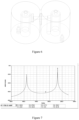
- the simulation result is shown in Fig. 5 .
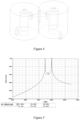
- a cavity filter is simulated, and the simulation results are shown in Fig. 7 .
- the distance between the end of the second coupling part 302 away from the insulating support base 30 and the second resonator 201 is adjusted to obtain the coupling amount of the cavity filter. Table 1.
- the coupling amount of the embodiment of the present invention is at least 2 times greater than the conventional coupling amount.
- the coupling amount in the embodiment of the present invention is 0.05799, while the prior art coupling amount is 0.01933. That is, the coupling amount of the embodiment of the present invention is three times the prior art coupling amount.
- the first coupling part is grounded, and the end of the second coupling part away from the insulating support base is spaced from the second resonator to realize: adjustment of the distance between the end of the second coupling part away from the insulating support and the second resonator. Since the first coupling part is grounded, even if the distance between the second coupling part and the second resonator is relatively short, the coupling amount between the coupling fly rod and the resonator can be made larger.
- the coupling structure is adjusted by adjusting the distance between the second coupling part and the second resonator, and the obtained coupling amount between the flying bar and the resonator has a larger variation range , so as to meet the requirements of the coaxial cavity for the coupling amount, achieve different frequency bands and performance and quality assurance requirements, it can be applied to a variety of different application scenarios, and reduces costs.
Landscapes
- Physics & Mathematics (AREA)
- Electromagnetism (AREA)
- Control Of Motors That Do Not Use Commutators (AREA)
Description
- The present invention relates to the field of communication technology, in particular, to a cavity filter.
- Generally, the suppression of the filter is improved by adding a coupling structure in the cavity filter. At present, most of the coupling structure of the cavity filter is a "U" shaped structure or a "flying bar with disks at both ends" . However, due to the limited space, the "U"-shaped structure is not suitable for the cavity of a resonator with a flange.
- Please refer to
FIG. 1 , which is a prior art cavity filter. InFig. 1 , a cavity filter with a resonant cavity is taken as an example. A resonator is set inside each resonant cavity. As shown inFIG. 1 , acoupling structure 300 is a structure of "aflying bar 400 withcoupling discs 500 at both ends". Thecoupling structure 300 is installed in the cavity filter. For anyresonator 200, in order to achieve a strong capacitive cross-coupling, thecoupling discs 500 need to be very close to theresonator 200, which causes assembly difficulties. In addition, the coupling amount must be adjusted by adjusting the distance between theresonator 200 and thecoupling disc 500. As thecoupling disc 500 is very close to theresonator 200, the adjusting distance is limited, so that the adjustable range of the coupling amount between thecoupling structure 300 and theresonator 200 is limited, and thus cannot be adapted to many application scenarios. - Chinese patent publication No.
CN201417813Y , titled "Capacitive coupling interaction structure based on coaxial cavity resonator" discloses a capacitive coupling interaction structure based on a coaxial cavity resonator. The capacitive coupling interaction structure comprises a resonator housing, a resonator cover plate and a supporting body fly bar, wherein, the supporting body fly bar is supported in the resonator housing by an insulating medium; one end of a connection conductor is fixed at one end of the supporting body fly bar and electrically connected with the supporting body fly bar; and the other end of the connection conductor is fixed on the resonator cover plate and electrically connected with the resonator cover plate. Another publicationWO2017095035A1 titled "Cavity type wireless frequency filter having cross-coupling notch structure" relates to a cavity type wireless frequency filter having a cross-coupling notch structure, the filter comprising a notch substrate provided for cross-coupling between at least two resonance elements among a plurality of resonance elements, wherein the notch substrate comprises: a main substrate, which is made of a non-conductive material and has the first and second coupling structures mechanically coupled with at least two resonance elements, respectively; and a conductive line which is implemented by a conductive pattern formed on the main substrate and transfers a signal of a first resonance element to a second resonance element by using a non - contact coupling method. It is obvious that the current coupling structure makes the cavity filter unable to adapt to many application scenarios. - The embodiments of the present invention provide a cavity filter, according to claim 1, which can enhance the coupling amount and increase the adjustable range of the capacitive coupling.
- In a first aspect, the embodiment of the present invention provides a cavity filter as defined in claim 1.
- The capacitive cross-coupling structure includes:
- an insulating support base disposed between the first resonator and the second resonator; and
- a coupling fly bar disposed on the insulating support base, the coupling fly bar comprising a first coupling part disposed between the first resonator and the insulating support base and a second coupling part disposed between the second resonator and the insulating support base.
- Here, one end of the first coupling part far away from the insulating support base is grounded, and one end of the second coupling part far away from the insulating support base is suspended and spaced apart from the second resonator at an interval.
- In the two coupling parts of the coupling structure of the embodiment of the present invention, the first coupling part is grounded, and the distance between the end of the second coupling part far away from the insulating support base and the second resonator is maintained, so as to realize adj ustment of the distance between an end of the second coupling part away from the insulating support base and the second resonator, according to the required coupling amount. As the first coupling part is grounded, even if the distance between the second coupling part and the second resonator is relatively short, the coupling amount between the coupling fly bar and the resonator can be made larger. Compared with the prior art, in the embodiment of the present invention, the coupling structure is adjusted by adjusting the distance between the second coupling part and the second resonator, so that the resulting coupling range between the flying bar and the resonator is larger, which can be applied to a variety of different application scenarios.
- It also includes a support disposed between the insulating support base and the first resonator, and the end of the first coupling part far away from the insulating support base is disposed on the insulating support base for being grounded.
- The first coupling part is grounded with the first resonator through an intermediate piece, that is, a support piece, in a flexible manner.
- Optionally, the coupling fly bar is detachably disposed on the insulating support base.
- In the embodiment of the present invention, the coupling flying bar is detachably disposed on the insulating support base, then the coupling flying bar can be used in different coupling structures to obtain a variety of coupling structures and have a wider application range.
- Optionally, the interval between the end of the second coupling part far away from the insulating support base and the second resonator is greater than 1mm.
- In the embodiment of the present invention, the interval between the end of the second coupling part far away from the insulating support base and the second resonator is greater than 1mm. This can ensure that the distance between the end of the second coupling part far away from the insulating support base and the second resonator is not too small to adjust the coupling amount. Therefore, when the coupling structures are mass-produced, the coupling consistency of the mass-produced coupling structures can be ensured as much as possible.
- Optionally, the end of the first coupling part far away from the insulating support base is connected to the first resonator for being grounded; or, the end of the first coupling part far away from the insulating support base is connected to a bottom of a cavity defined between the first resonator and the insulating support base for being grounded.
- In the embodiment of the present invention, the first coupling part can be grounded in any one of the above ways, which is relatively flexible.
- Optionally, a coupling disc is provided at the end of the second coupling part far away from the insulating support base.
- In the embodiment of the present invention, when a cavity filter with a coupling structure is used, the distance between the coupling disc and the second resonator can be adjusted, or the diameter of the coupling disc can be adjusted. As a result, the coupling amount between the first coupling part and the first resonator and the coupling amount between the second coupling part and the second resonator are greater than the preset coupling amount, thereby realizing adjustment of the coupling amount in different ways.
- Optionally, the supporting piece and the first resonator are of an integral structure; or, the supporting piece and the first resonator are of a separated structure.
- In the embodiment of the present invention, the supporting piece and the first resonator may be of an integrated structure, which reduces the difficulty of adjustment, ensures the consistency of the production and assembly process, and improves the production efficiency.
- Optionally, the coupling fly bar is plated with a metal material.
- In the embodiment of the present invention, the coupling fly rod may be plated with a metal material to ensure that it has good conductivity as much as possible.
- Optionally it further includes a third resonator and a fourth resonator, wherein a center line between the third resonator and the fourth resonator is perpendicular to a center line between the first resonator and the second resonator.
- In the embodiment of the present invention, the coupling structure can also be applied to a filter with four resonant cavities to realize dual transmission zeros at the low end of the passband. Compared with the existing cavity filter, the coupling structure in the embodiment of the present invention can achieve a larger adjustment range of the coupling amount of the cavity filter, and can meet the existing cavity filter suppression requirements.
- In the two coupling parts of the coupling structure of the embodiment of the present invention, the first coupling part is grounded, and the distance between the end of the second coupling part far away from the insulating support base and the second resonator is maintained, to adjust the distance between the end of the second coupling part away from the insulating support base and the second resonator according to required coupling amount the requirement. Since the first coupling part is grounded, even if the distance between the second coupling part and the second resonator is relatively short, the coupling amount between the coupling fly bar and the resonator can be made larger. Compared with the prior art, in the embodiment of the present invention, the coupling structure is adjusted by adjusting the distance between the second coupling part and the second resonator, and the obtained coupling amount between the flying bar and the resonator has a larger range, and accordingly it can be applied to a variety of different application scenarios.
-
-
FIG. 1 is a schematic structural diagram of a cavity filter provided by prior art; -
FIG. 2 is a schematic diagram of a structure of a cavity filter provided by an embodiment of the present invention; -
FIG. 3 is a schematic diagram of a structure of a cavity filter provided by an embodiment of the present invention; -
FIG. 4 is a schematic diagram of a prior art cavity filter model; -
FIG. 5 is a schematic diagram of a model of a cavity filter provided infigure 4 ; -
Fig. 6 is a schematic diagram of a cavity filter; and -
FIG. 7 is a simulation diagram of the coupling amount range of a cavity filter. - In order to make the objectives, technical solutions and advantages of the present invention clearer, the technical solutions in the embodiments of the present invention will be described clearly and completely in conjunction with the accompanying drawings in the embodiments of the present invention.
- At present, a
coupling structure 300 of a cavity filter as shown inFIG. 1 is "aflying bar 400 withcoupling discs 500 at both ends". It adjusts the coupling amount by adjusting the distance between theresonator 200 and thecoupling disc 500. Since thecoupling disc 500 is very close to theresonator 200 and the adjustment distance is limited, the adjustable range of the coupling amount between thecoupling structure 300 and theresonator 200 is limited, and it cannot be adapted to many application scenarios. - In view of this, the embodiments of the present invention provide a cavity filter comprising a capacitive cross-coupling structure. Among the two coupling parts of the coupled flying bar of the capacitive cross-coupling structure, the first coupling part is grounded, and one end of the second coupling part away from the insulating support base is separated from the second resonator. This realizes that the distance between the end of the second coupling part away from the insulating support base and the second resonator can be adjusted according to the required coupling amount. Since the first coupling part is grounded, even if the distance between the second coupling part and the second resonator is relatively short, the coupling amount between the coupling fly rod and the resonator can be made larger, that is, the coupling amount of the cavity filter is large. Compared with the prior art, in the embodiment of the present invention, the coupling structure is adjusted by adjusting the distance between the second coupling part and the second resonator, and the obtained coupling amount between the flying bar and the resonator has a larger range, that is, the range of the coupling amount of the cavity filter is larger, so that it can be applied to a variety of different application scenarios.
- Referring to
FIG. 2 , an embodiment of the present invention comprises a capacitive cross-coupling structure, which is used to couple the energy. Here, thefirst resonator 101 is in a firstresonant cavity 10, and thesecond resonator 201 is in a secondresonant cavity 20. The capacitive cross-coupling structure includes an insulatingsupport base 30 and a coupling flying bar. Here, the insulatingsupport base 30 is arranged between thefirst resonator 101 and thesecond resonator 201. The coupling flying bar is arranged on the insulatingsupport base 30, and it includes afirst coupling part 301 arranged between thefirst resonator 201 and the insulatingsupport base 30, and afirst coupling part 301 arranged between thesecond resonator 201 and the insulatingsupport base 30 Thesecond coupling part 302. Here, thefirst resonator 101 is provided with a firstmetal tuning screw 102, and thesecond resonator 201 is provided with a secondmetal tuning screw 202. Thefirst coupling part 301 is used for coupling with thefirst resonator 101, and thesecond coupling part 302 is used for coupling with thesecond resonator 201. - It should be noted that, in the embodiment of the present invention, the
first coupling part 301 and thesecond coupling part 302 are not limited, as long as any one of the coupling parts in the coupling structure is grounded, and the distance between the other coupling part and the closer resonator is within a certain range. In the following, thefirst coupling part 301 is grounded for description. - In the embodiment of the present invention, the capacitive cross-coupling structure is applied to a cavity filter. When the capacitive cross-coupling structure is installed in the cavity of the cavity filter, the
first coupling part 301 is connected to the ground in the cavity filter, the end of thefirst coupling part 301 away from the insulatingsupport base 30 is grounded. A distance is maintained between the end of thesecond coupling part 302 away from the insulatingsupport base 30 and thesecond resonator 201. It can also be understood that the distance between the end of thesecond coupling part 302 away from the insulatingsupport base 30 and thesecond resonator 201 can be adjusted within a certain range to achieve at least two different coupling amounts . - In the embodiment of the present invention, when the cavity filter is produced, the initial distance between the end of the
second coupling part 302 away from the insulatingsupport base 30 and thesecond resonator 201 is greater than 1 mm. During production, due to fabrication errors, assembly errors, etc., the initial distance between the end of thesecond coupling part 302 away from the insulatingsupport base 30 and thesecond resonator 201 may be smaller. However, if the distance between the end of thesecond coupling part 302 away from the insulatingsupport base 30 and thesecond resonator 201 is small, it is difficult to adjust other resonators by adjusting one or some resonators of the cavity filter, and so, adjustment is more difficult. Therefore, the initial distance between the end of thesecond coupling part 302 away from the insulatingsupport base 30 and thesecond resonator 201 is greater than 1 mm, so as to ensure that distance of the end of the second coupling part away from the insulating support base and the second resonator is not too small, otherwise it is difficult to adjust the coupling amount. In this way, it can be ensured that when the coupling structures are mass-produced, the coupling consistency of the mass-produced coupling structures is better. - A prior art cavity filter is shown in
Fig. 1 . To achieve strong capacitive cross-coupling, for anyresonator 200, the distance between thecoupling disc 500 and theresonator 200 needs to be very close, which leads to limited adjustment distance. As a result, the adjustable range of the coupling amount between thecoupling structure 300 and theresonator 200 is limited, and the obtained coupling amount range is also limited. Comparatively, in the embodiment of the present invention, since thefirst coupling part 301 is grounded, if the coupling amount is to be the same as that inFIG. 1 , then, relative toFIG. 1 , the distance between the end of thesecond coupling part 302 far away from the insulating support base and thesecond resonator 201 will increase, which makes it easier to assemble and improves assembly efficiency. However, if the distance between the end of thesecond coupling part 302 away from the insulatingsupport base 30 and thesecond resonator 201 is the same as that between thecoupling disc 500 and theresonator 200 shown inFIG. 1 , then compared with the coupling amount between thecoupling disc 500 and theresonator 200 shown inFIG. 1 , in the embodiment of the present invention, the coupling amount between thesecond coupling part 302 and thesecond resonator 201 is larger, so that the coupling structure provided by the embodiment of the invention can further expand the range of the coupling amount and apply to more different application scenarios. - In the embodiment of the present invention, the
second coupling part 302 may be provided with acoupling disc 303, and the diameter of thecoupling disc 303 may be within a certain range. When using a cavity filter, the distance between thecoupling disc 303 and thesecond resonator 201 can be adjusted, or the diameter of thecoupling disc 303 can be adjusted to make the coupling amount between thefirst coupling part 301 and thefirst resonator 101 and the coupling amount between thesecond coupling part 302 and thesecond resonator 201, are greater than the preset coupling amount, so as to adjust the coupling amount in various ways. - In the embodiment of the present invention, the
first coupling part 301 may be grounded in various ways. In a possible implementation manner, an end of thefirst coupling part 301 away from the insulatingsupport base 30 may be connected to thefirst resonator 101 to be grounded. Alternatively, the end of thefirst coupling part 301 away from the insulatingsupport base 30 may be connected to a bottom of the cavity between thefirst resonator 201 and the insulatingsupport base 30 to be grounded. Since there is a certain height difference between the bottom of the cavity and thefirst coupling part 301, and the bottom of the cavity is located between thefirst coupling part 301 or thefirst resonator 201 and the insulatingsupport base 30, this makes it difficult to assemble when thefirst coupling part 301 is connected to the bottom of the cavity. In a possible implementation manner, thefirst coupling part 301 may be connected to a cover plate of thefirst resonator 201 to be grounded. Since the cover plate and thefirst coupling part 301 have a certain height difference, when thefirst coupling part 301 is connected to the cover plate, there is also a problem of difficulty in assembly. - In view of this, in the embodiment of the present invention, a support piece103 is further provided inside the first
resonant cavity 10, and thesupport piece 103 and thefirst resonator 101 are commonly grounded. In this way, by connecting thefirst coupling part 301 to thesupport piece 103, grounding can be achieved. In order to save space and to make the structural components in the cavity filter more stable, thesupport piece 103 can be fixed on thefirst resonator 101. If thesupport piece 103 and thefirst resonator 101 are of separate structure, thesupport piece 103 can be adhered to thefirst resonator 101 by possible fixing methods, for example, glue . Or, in order to be more stable, thesupport piece 103 and thefirst resonator 101 may be of an integral structure. The integrated design reduces the difficulty of adjustment and solves the industry's shortcomings, that is, during the adjustment process, due to assembly errors, thefirst resonator 101 is pulled to adjust the coupling amount. This ensures the consistency of the production assembly process, improves production efficiency, and is suitable for mass production. - In the embodiment of the present invention, the
support piece 103 may be a columnar body adapted to the shape of an outer wall of thefirst resonator 101, or thesupport piece 103 may be of a convex structure or other possible support structures. Thefirst coupling part 301 is fixed on thesupport piece 103 by a threadedconnective member 104 . If the threadedconnective member 104 is made of metal material, the threadedconnective member 104 needs to be plated with a certain thickness of metal material to ensure good conductivity. In the embodiment of the present invention, the inside of the firstresonant cavity 10, the secondresonant cavity 20, the coupling fly rod, etc. may be plated with a certain thickness of metal material, such as gold, silver or copper, to maintain good conductivity as much as possible. - Referring to
FIG. 3 , the capacitive cross-coupling structure provided by the embodiment of the present invention can be applied to a cavity filter with four resonant cavities. As shown inFIG. 3 , a thirdresonant cavity 40 includes athird resonator 401, and a fourthresonant cavity 50 includes afourth resonator 501. A center line of the thirdresonant cavity 40 and the fourthresonant cavity 50 and is perpendicular to that of the firstresonant cavity 10 and thesecond cavity 20. The coupling structure can be placed in the middle of the four resonators to achieve dual transmission zeros at the low end of the passband. Compared with a prior art cavity filter, the coupling structure in the embodiment of the present invention can achieve a larger adjustment range of the coupling amount of the cavity filter, and can meet the suppression requirements that the prior art cavity filter is difficult to achieve. - In order to facilitate understanding, the following experimental data illustrates that the coupling structure provided by the embodiment of the present invention makes the adjustment range of the coupling amount of the cavity filter larger. As shown in
FIG. 4 , the cavity filter is simulated while keeping the cavity size of the cavity filter and the frequency point of the communication center the same. The simulation result is shown inFig. 5 . As shown inFig. 6 , a cavity filter is simulated, and the simulation results are shown inFig. 7 . The distance between the end of thesecond coupling part 302 away from the insulatingsupport base 30 and thesecond resonator 201 is adjusted to obtain the coupling amount of the cavity filter.Table 1. Data table of the prior art coupling amount and the coupling amount of the embodiment of the present invention Dista nce (mm) Realized frequency band (MHz) Center frequen cy (MHz) Prior art coupling amount Coupling amount of the embodiment of the present invention Increase ratio of coupling amount 3 790-862 776 0.00773 0.02835 266.8% 2 790-862 776 0.01030 0.03727 261.8% 1.5 790-862 776 0.01418 0.04382 209.0% 1 790-862 776 0.01933 0.05799 200.0% - It can be seen from Table 1 that when the distance between the end of the
second coupling part 302 away from the insulatingsupport base 30 and thesecond resonator 201 is the same, the coupling amount of the embodiment of the present invention is at least 2 times greater than the conventional coupling amount. For example, when the distance between thesecond coupling part 302 and thesecond resonator 201 is 1mm, the coupling amount in the embodiment of the present invention is 0.05799, while the prior art coupling amount is 0.01933. That is, the coupling amount of the embodiment of the present invention is three times the prior art coupling amount. - In summary, among the two coupling parts of the coupling structure of the embodiment of the present invention, the first coupling part is grounded, and the end of the second coupling part away from the insulating support base is spaced from the second resonator to realize: adjustment of the distance between the end of the second coupling part away from the insulating support and the second resonator. Since the first coupling part is grounded, even if the distance between the second coupling part and the second resonator is relatively short, the coupling amount between the coupling fly rod and the resonator can be made larger. Compared with the prior art, in the embodiment of the present invention, the coupling structure is adjusted by adjusting the distance between the second coupling part and the second resonator, and the obtained coupling amount between the flying bar and the resonator has a larger variation range , so as to meet the requirements of the coaxial cavity for the coupling amount, achieve different frequency bands and performance and quality assurance requirements, it can be applied to a variety of different application scenarios, and reduces costs.
- Those skilled in the art can clearly understand that for the convenience and conciseness of the description, only the division of the above-mentioned functional modules is used as an example. In actual applications, the above-mentioned functions can be allocated by different functional modules as required, namely the internal structure of the device is divided into different functional modules to complete all or part of the functions described above.
- Obviously, those skilled in the art can make various changes and modifications to the present invention without departing from the scope of the claims .
Claims (8)
- A cavity filter , comprising : a first resonator (101), a second resonator (201) and a capacitive cross-coupling structure for coupling energy of the first resonator (101) and the second resonator (201), wherein the capacitive cross-coupling structure comprises:an insulating support base (30) disposed between the first resonator (101) and the second resonator (201); anda coupling fly bar disposed on the insulating support base (30), the coupling fly bar comprising a first coupling part (301) disposed between the first resonator (101) and the insulating support base (30) and a second coupling part (302) disposed between the second resonator (201) and the insulating support base (30);wherein one end of the first coupling part far away from the insulating support base (30) is grounded, and one end of the second coupling part far away from the insulating support base (30) is suspended and spaced apart from the second resonator (201) at an interval;further comprising:
a support piece (103) disposed between the insulating support base (30) and the first resonator (101), wherein the end of the first coupling part far away from the insulating support base is disposed on the support piece (103) for being grounded, characterized in that the end of the first coupling part far away from the insulating support base is fixed on the support piece (103) through a threaded connective member (104). - The cavity filter of claim 1, characterized in that the coupling fly bar is detachably disposed on the insulating support base (30).
- The cavity filter of claim 1, characterized in that the interval between the end of the second coupling part far away from the insulating support base and the second resonator (201) is greater than 1mm.
- The cavity filter of claim 1, characterized in that the end of the first coupling part far away from the insulating support base is connected to the first resonator (101) for being grounded; or
the end of the first coupling part far away from the insulating support base is connected to a bottom of a cavity defined between the first resonator (101) and the insulating support base (30) for being grounded. - The cavity filter of claim 1, characterized in that a coupling disc is provided at the end of the second coupling part far away from the insulating support base .
- The cavity filter of claim 1, characterized in that the coupling fly bar is plated with metal material.
- The cavity filter of any one of claims 1 to 6, characterized in further comprising a cavity, wherein the capacitive cross-coupling structure is provided within the cavity.
- The cavity filter of claim 1, further comprising:a third resonator; anda fourth resonator,characterized in that a center line between the third resonator and the fourth resonator is perpendicular to a center line between the first resonator and the second resonator.
Applications Claiming Priority (2)
| Application Number | Priority Date | Filing Date | Title |
|---|---|---|---|
| CN201810768244.2A CN108649303A (en) | 2018-07-13 | 2018-07-13 | A kind of capacitive coupling interaction structure and cavity body filter |
| PCT/CN2019/090793 WO2020010984A1 (en) | 2018-07-13 | 2019-06-11 | Capacitive cross-coupling structure and cavity filter |
Publications (3)
| Publication Number | Publication Date |
|---|---|
| EP3823090A1 EP3823090A1 (en) | 2021-05-19 |
| EP3823090A4 EP3823090A4 (en) | 2022-04-20 |
| EP3823090B1 true EP3823090B1 (en) | 2024-08-21 |
Family
ID=63751614
Family Applications (1)
| Application Number | Title | Priority Date | Filing Date |
|---|---|---|---|
| EP19835085.2A Active EP3823090B1 (en) | 2018-07-13 | 2019-06-11 | Capacitive cross-coupling structure and cavity filter |
Country Status (5)
| Country | Link |
|---|---|
| EP (1) | EP3823090B1 (en) |
| CN (1) | CN108649303A (en) |
| BR (1) | BR112021000431A2 (en) |
| ES (1) | ES2987801T3 (en) |
| WO (1) | WO2020010984A1 (en) |
Families Citing this family (7)
| Publication number | Priority date | Publication date | Assignee | Title |
|---|---|---|---|---|
| CN108649303A (en) * | 2018-07-13 | 2018-10-12 | 京信通信系统(中国)有限公司 | A kind of capacitive coupling interaction structure and cavity body filter |
| JP7470197B2 (en) * | 2020-02-20 | 2024-04-17 | ケーエムダブリュ・インコーポレーテッド | Cavity filter and manufacturing method thereof |
| CN111463532A (en) * | 2020-05-21 | 2020-07-28 | 江苏贝孚德通讯科技股份有限公司 | Cross-coupling components and filters with cross-coupling components |
| CN113851803A (en) * | 2020-06-28 | 2021-12-28 | 大富科技(安徽)股份有限公司 | Filter and communication equipment |
| CN113964463A (en) * | 2020-07-21 | 2022-01-21 | 大富科技(安徽)股份有限公司 | Filter, flying rod clamping seat and communication equipment |
| CN113922022A (en) * | 2021-10-25 | 2022-01-11 | 苏州诺泰信通讯有限公司 | Superstrong capacitive coupling implementation structure |
| CN114024112B (en) * | 2021-12-08 | 2022-12-30 | 江苏贝孚德通讯科技股份有限公司 | Direct-discharge cavity capacitive coupling structure and coupling method |
Family Cites Families (12)
| Publication number | Priority date | Publication date | Assignee | Title |
|---|---|---|---|---|
| US6836198B2 (en) * | 2001-12-21 | 2004-12-28 | Radio Frequency Systems, Inc. | Adjustable capacitive coupling structure |
| US6924718B2 (en) * | 2002-12-04 | 2005-08-02 | Rs Microwave Company | Coupling probe having an adjustable tuning conductor |
| EP1895615A1 (en) * | 2006-08-31 | 2008-03-05 | Matsushita Electric Industrial Co., Ltd. | Adjustable coupling |
| CN101009396B (en) * | 2007-01-18 | 2010-11-10 | 华为技术有限公司 | Directional coupler and the device with the same |
| CN101527380B (en) * | 2009-04-22 | 2012-10-24 | 京信通信系统(中国)有限公司 | Cavity radio frequency apparatus with capacitive cross coupling device |
| CN201417813Y (en) * | 2009-05-06 | 2010-03-03 | 摩比天线技术(深圳)有限公司 | Capacitive coupling interaction structure based on coaxial cavity resonator |
| CN201877546U (en) * | 2010-11-26 | 2011-06-22 | 武汉凡谷电子技术股份有限公司 | Cross coupler of cavity filter |
| KR101756124B1 (en) * | 2015-11-30 | 2017-07-11 | 주식회사 케이엠더블유 | Cavity type radio frequency filter with cross-coupling notch structure |
| CN206116568U (en) * | 2016-08-29 | 2017-04-19 | 广东通宇通讯股份有限公司 | Filter |
| CN206313107U (en) * | 2016-12-20 | 2017-07-07 | 京信通信系统(中国)有限公司 | Hybrid guided mode radio-frequency filter |
| CN108649303A (en) * | 2018-07-13 | 2018-10-12 | 京信通信系统(中国)有限公司 | A kind of capacitive coupling interaction structure and cavity body filter |
| CN208298985U (en) * | 2018-07-13 | 2018-12-28 | 京信通信系统(中国)有限公司 | A kind of capacitive coupling interaction structure and cavity body filter |
-
2018
- 2018-07-13 CN CN201810768244.2A patent/CN108649303A/en active Pending
-
2019
- 2019-06-11 WO PCT/CN2019/090793 patent/WO2020010984A1/en not_active Ceased
- 2019-06-11 BR BR112021000431-9A patent/BR112021000431A2/en unknown
- 2019-06-11 EP EP19835085.2A patent/EP3823090B1/en active Active
- 2019-06-11 ES ES19835085T patent/ES2987801T3/en active Active
Also Published As
| Publication number | Publication date |
|---|---|
| EP3823090A1 (en) | 2021-05-19 |
| EP3823090A4 (en) | 2022-04-20 |
| ES2987801T3 (en) | 2024-11-18 |
| WO2020010984A1 (en) | 2020-01-16 |
| BR112021000431A2 (en) | 2021-04-06 |
| CN108649303A (en) | 2018-10-12 |
Similar Documents
| Publication | Publication Date | Title |
|---|---|---|
| EP3823090A1 (en) | Capacitive cross-coupling structure and cavity filter | |
| KR101797519B1 (en) | ceramic cavity filter | |
| US9979070B2 (en) | Resonator, filter, duplexer, multiplexer, and communications device | |
| CN103262338B (en) | Tunable high frequency filter | |
| CN108701886A (en) | Cavity RF Filter with Cross-Coupled Notch Structure | |
| CN110323553B (en) | Antenna radiation unit and antenna | |
| US7969260B2 (en) | Variable radio frequency band filter | |
| CN106463807B (en) | Tuned cell for rf-resonator | |
| JPS638641B2 (en) | ||
| CN103985933B (en) | The multi-vibration-mode filter of transmission zero can be adjusted | |
| CN113258271A (en) | AFU antenna structure | |
| CN109768356B (en) | Miniature multimode filter switch based on cavity resonator | |
| CN208298985U (en) | A kind of capacitive coupling interaction structure and cavity body filter | |
| TWI708425B (en) | Resonator, filter and communication device | |
| CN115483522B (en) | Metal resonator | |
| KR101605863B1 (en) | Dieletric Resonator Filter | |
| CN214849031U (en) | AFU Antenna Structure | |
| US12519201B2 (en) | Bias tees having a capacitance to ground | |
| CN213905567U (en) | Spiral line cavity filter | |
| CN211126002U (en) | Communication equipment, filter and resonator thereof | |
| KR100703719B1 (en) | Resonator filter coupled with curved conductor plate | |
| CN112768861A (en) | Coupling structure for filter, filter and radio frequency device | |
| JPWO2005062415A1 (en) | Dielectric resonator and communication device using the same | |
| KR20160008486A (en) | Cavity Filter Including Coxial Resonator | |
| JPS6390201A (en) | Dielectric filter |
Legal Events
| Date | Code | Title | Description |
|---|---|---|---|
| STAA | Information on the status of an ep patent application or granted ep patent |
Free format text: STATUS: THE INTERNATIONAL PUBLICATION HAS BEEN MADE |
|
| PUAI | Public reference made under article 153(3) epc to a published international application that has entered the european phase |
Free format text: ORIGINAL CODE: 0009012 |
|
| STAA | Information on the status of an ep patent application or granted ep patent |
Free format text: STATUS: REQUEST FOR EXAMINATION WAS MADE |
|
| 17P | Request for examination filed |
Effective date: 20210205 |
|
| AK | Designated contracting states |
Kind code of ref document: A1 Designated state(s): AL AT BE BG CH CY CZ DE DK EE ES FI FR GB GR HR HU IE IS IT LI LT LU LV MC MK MT NL NO PL PT RO RS SE SI SK SM TR |
|
| DAV | Request for validation of the european patent (deleted) | ||
| DAX | Request for extension of the european patent (deleted) | ||
| A4 | Supplementary search report drawn up and despatched |
Effective date: 20220322 |
|
| RIC1 | Information provided on ipc code assigned before grant |
Ipc: H01P 1/205 20060101ALI20220316BHEP Ipc: H01P 1/208 20060101AFI20220316BHEP |
|
| P01 | Opt-out of the competence of the unified patent court (upc) registered |
Effective date: 20230517 |
|
| GRAP | Despatch of communication of intention to grant a patent |
Free format text: ORIGINAL CODE: EPIDOSNIGR1 |
|
| STAA | Information on the status of an ep patent application or granted ep patent |
Free format text: STATUS: GRANT OF PATENT IS INTENDED |
|
| INTG | Intention to grant announced |
Effective date: 20240523 |
|
| GRAS | Grant fee paid |
Free format text: ORIGINAL CODE: EPIDOSNIGR3 |
|
| GRAA | (expected) grant |
Free format text: ORIGINAL CODE: 0009210 |
|
| STAA | Information on the status of an ep patent application or granted ep patent |
Free format text: STATUS: THE PATENT HAS BEEN GRANTED |
|
| AK | Designated contracting states |
Kind code of ref document: B1 Designated state(s): AL AT BE BG CH CY CZ DE DK EE ES FI FR GB GR HR HU IE IS IT LI LT LU LV MC MK MT NL NO PL PT RO RS SE SI SK SM TR |
|
| REG | Reference to a national code |
Ref country code: GB Ref legal event code: FG4D |
|
| REG | Reference to a national code |
Ref country code: CH Ref legal event code: EP |
|
| REG | Reference to a national code |
Ref country code: DE Ref legal event code: R096 Ref document number: 602019057562 Country of ref document: DE |
|
| REG | Reference to a national code |
Ref country code: IE Ref legal event code: FG4D |
|
| REG | Reference to a national code |
Ref country code: ES Ref legal event code: FG2A Ref document number: 2987801 Country of ref document: ES Kind code of ref document: T3 Effective date: 20241118 |
|
| REG | Reference to a national code |
Ref country code: LT Ref legal event code: MG9D |
|
| REG | Reference to a national code |
Ref country code: NL Ref legal event code: MP Effective date: 20240821 |
|
| PG25 | Lapsed in a contracting state [announced via postgrant information from national office to epo] |
Ref country code: NO Free format text: LAPSE BECAUSE OF FAILURE TO SUBMIT A TRANSLATION OF THE DESCRIPTION OR TO PAY THE FEE WITHIN THE PRESCRIBED TIME-LIMIT Effective date: 20241121 |
|
| REG | Reference to a national code |
Ref country code: AT Ref legal event code: MK05 Ref document number: 1716445 Country of ref document: AT Kind code of ref document: T Effective date: 20240821 |
|
| PG25 | Lapsed in a contracting state [announced via postgrant information from national office to epo] |
Ref country code: NL Free format text: LAPSE BECAUSE OF FAILURE TO SUBMIT A TRANSLATION OF THE DESCRIPTION OR TO PAY THE FEE WITHIN THE PRESCRIBED TIME-LIMIT Effective date: 20240821 Ref country code: GR Free format text: LAPSE BECAUSE OF FAILURE TO SUBMIT A TRANSLATION OF THE DESCRIPTION OR TO PAY THE FEE WITHIN THE PRESCRIBED TIME-LIMIT Effective date: 20241122 Ref country code: FI Free format text: LAPSE BECAUSE OF FAILURE TO SUBMIT A TRANSLATION OF THE DESCRIPTION OR TO PAY THE FEE WITHIN THE PRESCRIBED TIME-LIMIT Effective date: 20240821 Ref country code: PL Free format text: LAPSE BECAUSE OF FAILURE TO SUBMIT A TRANSLATION OF THE DESCRIPTION OR TO PAY THE FEE WITHIN THE PRESCRIBED TIME-LIMIT Effective date: 20240821 Ref country code: PT Free format text: LAPSE BECAUSE OF FAILURE TO SUBMIT A TRANSLATION OF THE DESCRIPTION OR TO PAY THE FEE WITHIN THE PRESCRIBED TIME-LIMIT Effective date: 20241223 |
|
| PG25 | Lapsed in a contracting state [announced via postgrant information from national office to epo] |
Ref country code: BG Free format text: LAPSE BECAUSE OF FAILURE TO SUBMIT A TRANSLATION OF THE DESCRIPTION OR TO PAY THE FEE WITHIN THE PRESCRIBED TIME-LIMIT Effective date: 20240821 |
|
| PG25 | Lapsed in a contracting state [announced via postgrant information from national office to epo] |
Ref country code: LV Free format text: LAPSE BECAUSE OF FAILURE TO SUBMIT A TRANSLATION OF THE DESCRIPTION OR TO PAY THE FEE WITHIN THE PRESCRIBED TIME-LIMIT Effective date: 20240821 |
|
| PG25 | Lapsed in a contracting state [announced via postgrant information from national office to epo] |
Ref country code: AT Free format text: LAPSE BECAUSE OF FAILURE TO SUBMIT A TRANSLATION OF THE DESCRIPTION OR TO PAY THE FEE WITHIN THE PRESCRIBED TIME-LIMIT Effective date: 20240821 Ref country code: IS Free format text: LAPSE BECAUSE OF FAILURE TO SUBMIT A TRANSLATION OF THE DESCRIPTION OR TO PAY THE FEE WITHIN THE PRESCRIBED TIME-LIMIT Effective date: 20241221 |
|
| PG25 | Lapsed in a contracting state [announced via postgrant information from national office to epo] |
Ref country code: HR Free format text: LAPSE BECAUSE OF FAILURE TO SUBMIT A TRANSLATION OF THE DESCRIPTION OR TO PAY THE FEE WITHIN THE PRESCRIBED TIME-LIMIT Effective date: 20240821 |
|
| PG25 | Lapsed in a contracting state [announced via postgrant information from national office to epo] |
Ref country code: RS Free format text: LAPSE BECAUSE OF FAILURE TO SUBMIT A TRANSLATION OF THE DESCRIPTION OR TO PAY THE FEE WITHIN THE PRESCRIBED TIME-LIMIT Effective date: 20241121 |
|
| PG25 | Lapsed in a contracting state [announced via postgrant information from national office to epo] |
Ref country code: RS Free format text: LAPSE BECAUSE OF FAILURE TO SUBMIT A TRANSLATION OF THE DESCRIPTION OR TO PAY THE FEE WITHIN THE PRESCRIBED TIME-LIMIT Effective date: 20241121 Ref country code: PT Free format text: LAPSE BECAUSE OF FAILURE TO SUBMIT A TRANSLATION OF THE DESCRIPTION OR TO PAY THE FEE WITHIN THE PRESCRIBED TIME-LIMIT Effective date: 20241223 Ref country code: PL Free format text: LAPSE BECAUSE OF FAILURE TO SUBMIT A TRANSLATION OF THE DESCRIPTION OR TO PAY THE FEE WITHIN THE PRESCRIBED TIME-LIMIT Effective date: 20240821 Ref country code: NO Free format text: LAPSE BECAUSE OF FAILURE TO SUBMIT A TRANSLATION OF THE DESCRIPTION OR TO PAY THE FEE WITHIN THE PRESCRIBED TIME-LIMIT Effective date: 20241121 Ref country code: NL Free format text: LAPSE BECAUSE OF FAILURE TO SUBMIT A TRANSLATION OF THE DESCRIPTION OR TO PAY THE FEE WITHIN THE PRESCRIBED TIME-LIMIT Effective date: 20240821 Ref country code: LV Free format text: LAPSE BECAUSE OF FAILURE TO SUBMIT A TRANSLATION OF THE DESCRIPTION OR TO PAY THE FEE WITHIN THE PRESCRIBED TIME-LIMIT Effective date: 20240821 Ref country code: IS Free format text: LAPSE BECAUSE OF FAILURE TO SUBMIT A TRANSLATION OF THE DESCRIPTION OR TO PAY THE FEE WITHIN THE PRESCRIBED TIME-LIMIT Effective date: 20241221 Ref country code: HR Free format text: LAPSE BECAUSE OF FAILURE TO SUBMIT A TRANSLATION OF THE DESCRIPTION OR TO PAY THE FEE WITHIN THE PRESCRIBED TIME-LIMIT Effective date: 20240821 Ref country code: GR Free format text: LAPSE BECAUSE OF FAILURE TO SUBMIT A TRANSLATION OF THE DESCRIPTION OR TO PAY THE FEE WITHIN THE PRESCRIBED TIME-LIMIT Effective date: 20241122 Ref country code: FI Free format text: LAPSE BECAUSE OF FAILURE TO SUBMIT A TRANSLATION OF THE DESCRIPTION OR TO PAY THE FEE WITHIN THE PRESCRIBED TIME-LIMIT Effective date: 20240821 Ref country code: BG Free format text: LAPSE BECAUSE OF FAILURE TO SUBMIT A TRANSLATION OF THE DESCRIPTION OR TO PAY THE FEE WITHIN THE PRESCRIBED TIME-LIMIT Effective date: 20240821 Ref country code: AT Free format text: LAPSE BECAUSE OF FAILURE TO SUBMIT A TRANSLATION OF THE DESCRIPTION OR TO PAY THE FEE WITHIN THE PRESCRIBED TIME-LIMIT Effective date: 20240821 |
|
| PG25 | Lapsed in a contracting state [announced via postgrant information from national office to epo] |
Ref country code: SM Free format text: LAPSE BECAUSE OF FAILURE TO SUBMIT A TRANSLATION OF THE DESCRIPTION OR TO PAY THE FEE WITHIN THE PRESCRIBED TIME-LIMIT Effective date: 20240821 Ref country code: RO Free format text: LAPSE BECAUSE OF FAILURE TO SUBMIT A TRANSLATION OF THE DESCRIPTION OR TO PAY THE FEE WITHIN THE PRESCRIBED TIME-LIMIT Effective date: 20240821 Ref country code: DK Free format text: LAPSE BECAUSE OF FAILURE TO SUBMIT A TRANSLATION OF THE DESCRIPTION OR TO PAY THE FEE WITHIN THE PRESCRIBED TIME-LIMIT Effective date: 20240821 |
|
| PG25 | Lapsed in a contracting state [announced via postgrant information from national office to epo] |
Ref country code: EE Free format text: LAPSE BECAUSE OF FAILURE TO SUBMIT A TRANSLATION OF THE DESCRIPTION OR TO PAY THE FEE WITHIN THE PRESCRIBED TIME-LIMIT Effective date: 20240821 |
|
| PG25 | Lapsed in a contracting state [announced via postgrant information from national office to epo] |
Ref country code: CZ Free format text: LAPSE BECAUSE OF FAILURE TO SUBMIT A TRANSLATION OF THE DESCRIPTION OR TO PAY THE FEE WITHIN THE PRESCRIBED TIME-LIMIT Effective date: 20240821 |
|
| PG25 | Lapsed in a contracting state [announced via postgrant information from national office to epo] |
Ref country code: SK Free format text: LAPSE BECAUSE OF FAILURE TO SUBMIT A TRANSLATION OF THE DESCRIPTION OR TO PAY THE FEE WITHIN THE PRESCRIBED TIME-LIMIT Effective date: 20240821 |
|
| REG | Reference to a national code |
Ref country code: DE Ref legal event code: R097 Ref document number: 602019057562 Country of ref document: DE |
|
| PLBE | No opposition filed within time limit |
Free format text: ORIGINAL CODE: 0009261 |
|
| STAA | Information on the status of an ep patent application or granted ep patent |
Free format text: STATUS: NO OPPOSITION FILED WITHIN TIME LIMIT |
|
| 26N | No opposition filed |
Effective date: 20250522 |
|
| PG25 | Lapsed in a contracting state [announced via postgrant information from national office to epo] |
Ref country code: SE Free format text: LAPSE BECAUSE OF FAILURE TO SUBMIT A TRANSLATION OF THE DESCRIPTION OR TO PAY THE FEE WITHIN THE PRESCRIBED TIME-LIMIT Effective date: 20240821 |
|
| PGFP | Annual fee paid to national office [announced via postgrant information from national office to epo] |
Ref country code: ES Payment date: 20250731 Year of fee payment: 7 |
|
| PGFP | Annual fee paid to national office [announced via postgrant information from national office to epo] |
Ref country code: IT Payment date: 20250624 Year of fee payment: 7 |
|
| REG | Reference to a national code |
Ref country code: DE Ref legal event code: R119 Ref document number: 602019057562 Country of ref document: DE |
|
| REG | Reference to a national code |
Ref country code: CH Ref legal event code: H13 Free format text: ST27 STATUS EVENT CODE: U-0-0-H10-H13 (AS PROVIDED BY THE NATIONAL OFFICE) Effective date: 20260127 |
|
| PG25 | Lapsed in a contracting state [announced via postgrant information from national office to epo] |
Ref country code: MC Free format text: LAPSE BECAUSE OF FAILURE TO SUBMIT A TRANSLATION OF THE DESCRIPTION OR TO PAY THE FEE WITHIN THE PRESCRIBED TIME-LIMIT Effective date: 20240821 |
|
| PG25 | Lapsed in a contracting state [announced via postgrant information from national office to epo] |
Ref country code: LU Free format text: LAPSE BECAUSE OF NON-PAYMENT OF DUE FEES Effective date: 20250611 |
|
| GBPC | Gb: european patent ceased through non-payment of renewal fee |
Effective date: 20250611 |
|
| REG | Reference to a national code |
Ref country code: BE Ref legal event code: MM Effective date: 20250630 |
|
| PG25 | Lapsed in a contracting state [announced via postgrant information from national office to epo] |
Ref country code: GB Free format text: LAPSE BECAUSE OF NON-PAYMENT OF DUE FEES Effective date: 20250611 |
|
| PG25 | Lapsed in a contracting state [announced via postgrant information from national office to epo] |
Ref country code: IE Free format text: LAPSE BECAUSE OF NON-PAYMENT OF DUE FEES Effective date: 20250611 Ref country code: DE Free format text: LAPSE BECAUSE OF NON-PAYMENT OF DUE FEES Effective date: 20260101 |
|
| PG25 | Lapsed in a contracting state [announced via postgrant information from national office to epo] |
Ref country code: BE Free format text: LAPSE BECAUSE OF NON-PAYMENT OF DUE FEES Effective date: 20250630 |
|
| PG25 | Lapsed in a contracting state [announced via postgrant information from national office to epo] |
Ref country code: FR Free format text: LAPSE BECAUSE OF NON-PAYMENT OF DUE FEES Effective date: 20250630 |
|
| PG25 | Lapsed in a contracting state [announced via postgrant information from national office to epo] |
Ref country code: CH Free format text: LAPSE BECAUSE OF NON-PAYMENT OF DUE FEES Effective date: 20250630 |