EP3823058A1 - Secondary battery - Google Patents
Secondary battery Download PDFInfo
- Publication number
- EP3823058A1 EP3823058A1 EP19850306.2A EP19850306A EP3823058A1 EP 3823058 A1 EP3823058 A1 EP 3823058A1 EP 19850306 A EP19850306 A EP 19850306A EP 3823058 A1 EP3823058 A1 EP 3823058A1
- Authority
- EP
- European Patent Office
- Prior art keywords
- cover
- coating part
- insulation coating
- main body
- secondary battery
- Prior art date
- Legal status (The legal status is an assumption and is not a legal conclusion. Google has not performed a legal analysis and makes no representation as to the accuracy of the status listed.)
- Pending
Links
Images





Classifications
-
- H—ELECTRICITY
- H01—ELECTRIC ELEMENTS
- H01M—PROCESSES OR MEANS, e.g. BATTERIES, FOR THE DIRECT CONVERSION OF CHEMICAL ENERGY INTO ELECTRICAL ENERGY
- H01M10/00—Secondary cells; Manufacture thereof
- H01M10/04—Construction or manufacture in general
- H01M10/0422—Cells or battery with cylindrical casing
- H01M10/0427—Button cells
-
- H—ELECTRICITY
- H01—ELECTRIC ELEMENTS
- H01M—PROCESSES OR MEANS, e.g. BATTERIES, FOR THE DIRECT CONVERSION OF CHEMICAL ENERGY INTO ELECTRICAL ENERGY
- H01M10/00—Secondary cells; Manufacture thereof
- H01M10/04—Construction or manufacture in general
- H01M10/0431—Cells with wound or folded electrodes
-
- H—ELECTRICITY
- H01—ELECTRIC ELEMENTS
- H01M—PROCESSES OR MEANS, e.g. BATTERIES, FOR THE DIRECT CONVERSION OF CHEMICAL ENERGY INTO ELECTRICAL ENERGY
- H01M50/00—Constructional details or processes of manufacture of the non-active parts of electrochemical cells other than fuel cells, e.g. hybrid cells
- H01M50/10—Primary casings; Jackets or wrappings
- H01M50/102—Primary casings; Jackets or wrappings characterised by their shape or physical structure
- H01M50/109—Primary casings; Jackets or wrappings characterised by their shape or physical structure of button or coin shape
-
- H—ELECTRICITY
- H01—ELECTRIC ELEMENTS
- H01M—PROCESSES OR MEANS, e.g. BATTERIES, FOR THE DIRECT CONVERSION OF CHEMICAL ENERGY INTO ELECTRICAL ENERGY
- H01M50/00—Constructional details or processes of manufacture of the non-active parts of electrochemical cells other than fuel cells, e.g. hybrid cells
- H01M50/10—Primary casings; Jackets or wrappings
- H01M50/116—Primary casings; Jackets or wrappings characterised by the material
- H01M50/117—Inorganic material
-
- H—ELECTRICITY
- H01—ELECTRIC ELEMENTS
- H01M—PROCESSES OR MEANS, e.g. BATTERIES, FOR THE DIRECT CONVERSION OF CHEMICAL ENERGY INTO ELECTRICAL ENERGY
- H01M50/00—Constructional details or processes of manufacture of the non-active parts of electrochemical cells other than fuel cells, e.g. hybrid cells
- H01M50/10—Primary casings; Jackets or wrappings
- H01M50/116—Primary casings; Jackets or wrappings characterised by the material
- H01M50/117—Inorganic material
- H01M50/119—Metals
-
- H—ELECTRICITY
- H01—ELECTRIC ELEMENTS
- H01M—PROCESSES OR MEANS, e.g. BATTERIES, FOR THE DIRECT CONVERSION OF CHEMICAL ENERGY INTO ELECTRICAL ENERGY
- H01M50/00—Constructional details or processes of manufacture of the non-active parts of electrochemical cells other than fuel cells, e.g. hybrid cells
- H01M50/10—Primary casings; Jackets or wrappings
- H01M50/116—Primary casings; Jackets or wrappings characterised by the material
- H01M50/121—Organic material
-
- H—ELECTRICITY
- H01—ELECTRIC ELEMENTS
- H01M—PROCESSES OR MEANS, e.g. BATTERIES, FOR THE DIRECT CONVERSION OF CHEMICAL ENERGY INTO ELECTRICAL ENERGY
- H01M50/00—Constructional details or processes of manufacture of the non-active parts of electrochemical cells other than fuel cells, e.g. hybrid cells
- H01M50/10—Primary casings; Jackets or wrappings
- H01M50/116—Primary casings; Jackets or wrappings characterised by the material
- H01M50/122—Composite material consisting of a mixture of organic and inorganic materials
-
- H—ELECTRICITY
- H01—ELECTRIC ELEMENTS
- H01M—PROCESSES OR MEANS, e.g. BATTERIES, FOR THE DIRECT CONVERSION OF CHEMICAL ENERGY INTO ELECTRICAL ENERGY
- H01M50/00—Constructional details or processes of manufacture of the non-active parts of electrochemical cells other than fuel cells, e.g. hybrid cells
- H01M50/10—Primary casings; Jackets or wrappings
- H01M50/116—Primary casings; Jackets or wrappings characterised by the material
- H01M50/124—Primary casings; Jackets or wrappings characterised by the material having a layered structure
-
- H—ELECTRICITY
- H01—ELECTRIC ELEMENTS
- H01M—PROCESSES OR MEANS, e.g. BATTERIES, FOR THE DIRECT CONVERSION OF CHEMICAL ENERGY INTO ELECTRICAL ENERGY
- H01M50/00—Constructional details or processes of manufacture of the non-active parts of electrochemical cells other than fuel cells, e.g. hybrid cells
- H01M50/10—Primary casings; Jackets or wrappings
- H01M50/116—Primary casings; Jackets or wrappings characterised by the material
- H01M50/124—Primary casings; Jackets or wrappings characterised by the material having a layered structure
- H01M50/1243—Primary casings; Jackets or wrappings characterised by the material having a layered structure characterised by the internal coating on the casing
-
- H—ELECTRICITY
- H01—ELECTRIC ELEMENTS
- H01M—PROCESSES OR MEANS, e.g. BATTERIES, FOR THE DIRECT CONVERSION OF CHEMICAL ENERGY INTO ELECTRICAL ENERGY
- H01M50/00—Constructional details or processes of manufacture of the non-active parts of electrochemical cells other than fuel cells, e.g. hybrid cells
- H01M50/10—Primary casings; Jackets or wrappings
- H01M50/131—Primary casings; Jackets or wrappings characterised by physical properties, e.g. gas permeability, size or heat resistance
- H01M50/133—Thickness
-
- H—ELECTRICITY
- H01—ELECTRIC ELEMENTS
- H01M—PROCESSES OR MEANS, e.g. BATTERIES, FOR THE DIRECT CONVERSION OF CHEMICAL ENERGY INTO ELECTRICAL ENERGY
- H01M50/00—Constructional details or processes of manufacture of the non-active parts of electrochemical cells other than fuel cells, e.g. hybrid cells
- H01M50/10—Primary casings; Jackets or wrappings
- H01M50/147—Lids or covers
- H01M50/148—Lids or covers characterised by their shape
- H01M50/153—Lids or covers characterised by their shape for button or coin cells
-
- H—ELECTRICITY
- H01—ELECTRIC ELEMENTS
- H01M—PROCESSES OR MEANS, e.g. BATTERIES, FOR THE DIRECT CONVERSION OF CHEMICAL ENERGY INTO ELECTRICAL ENERGY
- H01M50/00—Constructional details or processes of manufacture of the non-active parts of electrochemical cells other than fuel cells, e.g. hybrid cells
- H01M50/10—Primary casings; Jackets or wrappings
- H01M50/183—Sealing members
- H01M50/19—Sealing members characterised by the material
- H01M50/193—Organic material
-
- H—ELECTRICITY
- H01—ELECTRIC ELEMENTS
- H01M—PROCESSES OR MEANS, e.g. BATTERIES, FOR THE DIRECT CONVERSION OF CHEMICAL ENERGY INTO ELECTRICAL ENERGY
- H01M50/00—Constructional details or processes of manufacture of the non-active parts of electrochemical cells other than fuel cells, e.g. hybrid cells
- H01M50/40—Separators; Membranes; Diaphragms; Spacing elements inside cells
- H01M50/46—Separators, membranes or diaphragms characterised by their combination with electrodes
-
- H—ELECTRICITY
- H01—ELECTRIC ELEMENTS
- H01M—PROCESSES OR MEANS, e.g. BATTERIES, FOR THE DIRECT CONVERSION OF CHEMICAL ENERGY INTO ELECTRICAL ENERGY
- H01M50/00—Constructional details or processes of manufacture of the non-active parts of electrochemical cells other than fuel cells, e.g. hybrid cells
- H01M50/50—Current conducting connections for cells or batteries
- H01M50/531—Electrode connections inside a battery casing
-
- Y—GENERAL TAGGING OF NEW TECHNOLOGICAL DEVELOPMENTS; GENERAL TAGGING OF CROSS-SECTIONAL TECHNOLOGIES SPANNING OVER SEVERAL SECTIONS OF THE IPC; TECHNICAL SUBJECTS COVERED BY FORMER USPC CROSS-REFERENCE ART COLLECTIONS [XRACs] AND DIGESTS
- Y02—TECHNOLOGIES OR APPLICATIONS FOR MITIGATION OR ADAPTATION AGAINST CLIMATE CHANGE
- Y02E—REDUCTION OF GREENHOUSE GAS [GHG] EMISSIONS, RELATED TO ENERGY GENERATION, TRANSMISSION OR DISTRIBUTION
- Y02E60/00—Enabling technologies; Technologies with a potential or indirect contribution to GHG emissions mitigation
- Y02E60/10—Energy storage using batteries
-
- Y—GENERAL TAGGING OF NEW TECHNOLOGICAL DEVELOPMENTS; GENERAL TAGGING OF CROSS-SECTIONAL TECHNOLOGIES SPANNING OVER SEVERAL SECTIONS OF THE IPC; TECHNICAL SUBJECTS COVERED BY FORMER USPC CROSS-REFERENCE ART COLLECTIONS [XRACs] AND DIGESTS
- Y02—TECHNOLOGIES OR APPLICATIONS FOR MITIGATION OR ADAPTATION AGAINST CLIMATE CHANGE
- Y02P—CLIMATE CHANGE MITIGATION TECHNOLOGIES IN THE PRODUCTION OR PROCESSING OF GOODS
- Y02P70/00—Climate change mitigation technologies in the production process for final industrial or consumer products
- Y02P70/50—Manufacturing or production processes characterised by the final manufactured product
Definitions
- the present invention relate to a secondary battery.
- Secondary batteries are rechargeable unlike primarily batteries, and also, the possibility of compact size and high capacity is high. Thus, recently, many studies on rechargeable batteries are being carried out. As technology development and demands for mobile devices increase, the demands for rechargeable batteries as energy sources are rapidly increasing.
- Secondary batteries are classified into coin type batteries (button type batteries), cylindrical type batteries, prismatic type batteries, and pouch type batteries according to a shape of a battery case.
- an electrode assembly mounted in a battery case is a chargeable and dischargeable power generating device having a structure in which an electrode and a separator are stacked.
- the coin cell type secondary battery has high energy density and high output and also has long lifespan and high stability. That is, studies are being conducted on the coin cell having high voltage characteristics, output characteristics, and high energy density. In particular, it is an important issue to secure a wider accommodating space inside the battery case accommodating the electrode assembly, thereby increasing in energy density.
- One aspect of the prevent invention is to provide a secondary battery that is capable of maximizing an electrode assembly accommodation space within a can.
- a secondary battery according to an embodiment of the present invention comprises an electrode assembly in which an electrode and a separator are combined and staked, a can configured to accommodate the electrode assembly therein, and an insulation coating part that is insulation-applied to an inner surface of the can, wherein the insulation coating part may have a coating thickness of 1 ⁇ m to 15 ⁇ m.
- the insulation coating part is formed inside the can to omit the insulation structure that serves as the insulation part, the accommodation space of the electrode assembly may be maximized, and thus, the energy density may be improved.
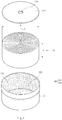
- FIG. 1 is a perspective view of a secondary battery according to a first embodiment of the present invention
- FIG. 2 is an exploded perspective view of an electrode assembly and a can in the secondary battery according to the first embodiment of the present invention
- FIG. 3 is a cross-sectional view taken along line A-A' of FIG. 1 .
- a secondary battery 100 according to a first embodiment of the present invention comprises an electrode assembly 110 in which an electrode 113 and a separator 114 are combined (or gathered) to be stacked, a can 120 accommodated in the electrode assembly 110, and an insulation coating part 170 that is applied to an inner surface of the can 120 so as to realize insulation.
- the electrode assembly 110 may be a chargeable and dischargeable power generation element and have a structure in which an electrode 113 and a separator 114 are combined and alternately stacked with each other.
- the electrode assembly 110 may have a wound shape.
- the electrode assembly 100 of the secondary battery 100 according to the embodiment of the present invention is not necessarily limited to the wound shape.
- the electrode assembly 100 may have a stack shape in which the electrode 113 and the separator 114 are alternately stacked in a plan shape.
- the electrode 113 may comprise a first electrode 111 and a second electrode 112.
- the separator 114 may separate the first electrode 111 from the second electrode 112 to insulate the first and second electrodes 111 and 112 from each other.
- each of the first electrode 111 and the second electrode may be provided in the form of a sheet and then be wound together with the separator 114 so as to be formed in a jelly roll type.
- the electrode assembly 110 may be wound, for example, in a cylindrical shape.
- the electrode assembly 110 may have a width w greater than a height h in a winding central axis C direction.
- the secondary battery according to the first embodiment of the present invention may be applied as a secondary battery having a button cell (coin cell) shape.
- the first electrode 111 may be provided as a positive electrode, and the second electrode 112 may be provided as a negative electrode.
- the first electrode 111 may not be necessarily limited to the positive electrode, and the second electrode 112 may not be necessarily limited to the negative electrode.
- the first electrode 111 may be provided as a negative electrode, and the second electrode 112 may be provided as a positive electrode.
- the positive electrode may comprise a positive electrode collector (not shown) and a positive electrode active material (not shown) applied to the positive electrode collector.
- the positive electrode collector may be provided as foil made of an aluminum material
- the positive electrode active material may be made of lithium manganese oxide, lithium cobalt oxide, lithium nickel oxide, lithium iron phosphate, or a compound or mixture thereof containing at least one or more of the above-described materials.
- the negative electrode may comprise a negative electrode collector (not shown) and a negative electrode active material (not shown) applied to the negative electrode collector.
- the negative electrode collector may be provided as foil made of a copper (Cu) or nickel (Ni) material.
- the negative electrode active material may comprise synthetic graphite, lithium a metal, a lithium alloy, carbon, petroleum coke, activated carbon, graphite, a silicon compound, a tin compound, a titanium compound, or an alloy thereof.
- the negative electrode active material may further comprise, for example, non-graphite-based SiO (silica) or SiC (silicon carbide).
- the separator 114 may be made of an insulating material, and the first electrode 111, the separator 114, and the second electrode 112 may be alternately stacked.
- the separator 114 may be disposed between the first electrode 111 and the second electrode on outer surfaces of the first electrode 111 and the second electrode 112.
- the separator 114 may be disposed at the outermost side in a width direction W when the electrode assembly 110 is wound.
- the separator 114 may be made of a flexible material.
- the separator 114 may be made of, for example, a polyolefin-based resin film such as polyethylene or polypropylene having micropores.
- the can 120 may accommodate the electrode assembly 110 therein and have a terminal hole 124 that is opened to one side.
- the can 120 may comprise a main body 121 comprising an accommodation part 123 in which the electrode assembly 110 is accommodated therein and a cover 122 covering the opening of the main body 121.
- the terminal hole 124 passing through the can 120 may be formed in the cover 122.
- the can 120 may have, for example, a cylindrical shape.
- the can 120 may comprise, for example, a metal material.
- the can 120 may comprise, for example, aluminum.
- the secondary battery according to the first embodiment of the present invention may further comprise a terminal that electrically connects the electrode assembly 110 to the outside.
- the terminal may be provided as a rivet terminal 130 having a rivet shape and closes the terminal hole 124 of the cover 122.
- a pillar may be formed in a longitudinal direction, and both ends extend in the width direction W.
- the longitudinal direction may be, for example, a height direction H as illustrated in FIG. 3 .
- the rivet terminal 130 may comprise a central portion 131 passing through the terminal hole 124, an outer portion 133 disposed outside the can 120, and an inner portion 132 disposed inside the can 120.
- the outer portion 133 and the inner portion 132 may extend in the width direction W of the electrode assembly 110.
- the rivet terminal 130 may not be separated from the cover 122 by the outer portion 133 and the inner portion 132. That is, each of a width of the outer portion 133 and a width of the inner portion 132 may be greater than a diameter of the terminal hole 124.
- the outer portion 133 and the inner portion 132 may be disposed at both vertical sides of the terminal hole 124 so that the rivet terminal 130 is prevented from the terminal hole 124 so as to be firmly coupled to each other.
- each of the outer portion 133 and the inner portion 132 may have a circular plate shape, and the central portion 131 may have a cylindrical shape.
- an outer diameter D2 of the outer portion 133 may be formed to be 80% or less of an outer diameter D1 of the can 120.
- the main body 121 of the can 120, a gasket 140, and the rivet terminal 130 may be prevented from interfering with each other.
- the gasket 140 may seal between the can 120 and the rivet terminal 130 to insulate the can 120 and the rivet terminal 130 from each other.
- the gasket 140 may comprise an electrically insulating and heat-resistant material.
- the gasket 140 may be integrated between the central portion 131, the outer portion 133, and the inner portion 132 of the rivet terminal 130 and the cover 122.
- the rivet terminal 130 and the cover 122 of the can 120 may be firmly coupled to each other to prevent the rivet terminal 130 from being connected to the can 120, thereby providing a safe structure that is capable of preventing electrical short-circuit from occurring.
- Both sides of a first electrode lead 150 may directly contact both sides of the first electrode 111 and the rivet terminal 130 to electrically connect the first electrode 111 to the rivet terminal 130.
- the first electrode lead 150 may extend from the rivet terminal 130 facing the electrode assembly 110 along a corresponding surface of the inner portion 132 and thus be connected to the inner portion 132.
- the first electrode lead 150 may be, for example, a positive electrode lead connected to the positive electrode of the electrode assembly 110.
- the secondary battery 100 may further comprise a first insulation plate 180 on a top surface of the electrode assembly 110, which faces the cover 122.
- the first insulation plate 180 may comprise an electrically insulating material.
- the electrode assembly 110 may be electrically connected to the first electrode lead 150 or the cover 122 to prevent the short circuit from occurring.
- the second electrode lead 160 may electrically connect the second electrode 112 to the can 120 (in particular, electrically connect the second electrode 112 to the main body 121).
- the second electrode lead 160 may be, for example, a negative electrode lead connected to the negative electrode of the electrode assembly 110.
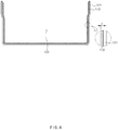
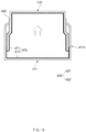
- FIG. 4 is a cross-sectional view illustrating the main body of the can in the secondary battery according to the first embodiment of the present invention.
- the insulation coating part 170 may comprise an insulating material so as to be insulation-applied to an inner surface of the can 120
- the insulation coating part 170 may comprise a ceramic material that is an insulating material.
- the insulation coating part 170 may comprise at least one or more of Al 2 O 3 or SiO 2 as the ceramic material.
- the insulation coating part 170 may realize an insulation effect through a thin coating thickness.
- the insulation coating part 170 may comprises, for example, Al 2 O 3 .
- the insulation coating part 170 may comprise Al 2 O 3 that is an insulating material having corrosion resistance and abrasion resistance to prevent the can 120 from being oxidized.
- the insulation coating part 170 may comprise Al 2 O 3 , which has a remarkable effect on the prevention of oxidation of aluminum (Al).
- the insulation coating part 170 may comprise Al 2 O 3 having strong abrasion resistance to maintain the insulation without being damaged by abrasion, friction, or an impact.
- the insulation coating part 170 may comprise aluminum oxide (Al 2 O 3 ), an organic binder, an inorganic binder, and alcohol.
- the insulation coating part 170 may be made of a composition for the insulation coating part, which comprises 10 wt% to 30 wt% of aluminum oxide (Al 2 O 3 ), 5 wt% to 25 wt% of an organic binder, 10 wt% to 30 wt% of an inorganic binder, and 20 wt% to 35 wt% of alcohol.
- the insulation coating part 170 may have remarkable insulation effect.
- the organic binder may be made of at least one or more materials of, for example, acetates, carboxylic acid, or ethers.
- the organic binder may be made of at least one or more materials of, for example, dipropyleneglycol monomethyl ether, vinyl acetate, isobuty acetate, or carboxylic acid. More specifically, the carboxylic acid may be selected from the group consisting of, for example, acrylic acid, methacrylic acid, itaconic acid, crotonic acid, fumaric acid, and maleic acid.
- the inorganic binder may be made of at least one or more of, for example, silicate, or boron nitride (BN).
- the inorganic binder may serve to reinforce the insulating property.
- the inorganic binder may comprise, for example, silicate.
- the alcohol may be made of at least one or more of ethanol, ethyl alcohol, or 2-isopropoxyethanol.
- the insulation coating part 170 may comprise SiO 2 as another example.
- the insulation coating part 170 may comprise SiO 2 , which is a high heat-resistant material, to insulate the electrode assembly 110 from the can 120 without losing the insulation even in a high temperature state when an internal temperature of the battery increases.
- the insulation coating part 170 may be made of a composition for the insulation coating part, which comprises SiO 2 , an organic binder, an inorganic binder, and alcohol.
- the insulation coating part 170 may comprises 10 wt% to 30 wt% of silicon oxide (SiO 2 ), 5 wt% to 25 wt% of an organic binder, 10 wt% to 30 wt% of an inorganic binder, and 20 wt% to 70 wt% of alcohol.
- the insulation coating part 170 may have remarkable insulation effect.
- the organic binder and the alcohol may be the same as those of the above-described example.
- the inorganic binder may be made of at least one or more of silicate, aluminum oxide (Al 2 O 3 ), or boron nitride (BN) .
- the insulation coating part 170 may comprise Al 2 O 3 and SiO 2 .
- the insulation coating part 170 may be made of a composition for the insulation coating part, which comprises aluminum oxide (Al 2 O 3 ) and silicon dioxide (SiO 2 ).
- the insulation coating part 170 may comprise 10 wt% to 30 wt% of aluminum oxide, 20 wt% to 50 wt% of silicon oxide, and 20 wt% to 70 wt% of alcohol.
- the insulation coating part 170 has remarkable insulation and a remarkably excellent electrolyte resistance effect.
- the alcohol may be the same as that of the above-described example.
- the insulation coating part 170 may comprise aluminum oxide (Al 2 O 3 ) as another example and may be made of a composition for the insulation coating part, which comprises aluminum oxide (Al 2 O 3 ), silicon-based rubber, and alcohol.
- the insulation coating part 170 may be made of, for example, a composition for the insulation coating part, which comprises 10 wt% to 30 wt% of aluminum oxide (Al 2 O 3 ), 20 wt% to 50 wt% of silicon-based rubber, and 20 wt% to 70 wt% of alcohol.
- the insulation coating part 170 has remarkable insulation and a remarkably excellent electrolyte resistance effect.
- the alcohol may be made of, for example, at least one or more of ethanol, ethyl alcohol, or 2-isopropoxyethanol. More specifically, the alcohol may be made of ethanol and 2-Isopropoxyethanol.
- the insulation coating part 170 may be formed on the inner surface of the can 120, for example, in the form of a film.
- the insulation coating part 170 may have a coating thickness of 0.5 ⁇ m to 30 ⁇ m.
- the insulation coating part 170 may have, for example, a coating thickness of 1 ⁇ m to 15 um.
- the insulation coating part 170 may have a thickness of 1 ⁇ m or more to ensure a thickness at which the insulation effect is capable of being realized.
- the insulation coating part 170 may have a thickness 15 ⁇ m or less to widely ensure an accommodation space of the can 120 accommodating the electrode assembly 110, thereby improving energy density.
- the insulation coating part 170 may be applied to cover an inner surface of the body 121 of the can 120.
- the insulation coating part 170 may have a coating thickness of 1 ⁇ m to 15 ⁇ m to improve the energy density while securing the thickness at which the insulation effect is capable of being realized, thereby significantly increasing in battery capacity.
- the insulation coating part 170 may be applied to cover inner surfaces of the body 121 and the cover 122 of the can 120.
- the insulation resistance of the insulation coating part 170 may be 2 MQ (Mega-Ohm) to 10 MQ, and a melting point of the insulation coating part 170 may be 800°C to 1500°C.
- the insulation coating part 170 may maximize the insulation effect and the heat resistance effect.
- the insulation coating part 170 may be formed on the inner surface of the can 120 to omit the insulation structure that serves as the insulation part, thereby maximizing the accommodation space of the electrode assembly 110 and also improving the energy density to significantly increase in battery capacity.
- the secondary battery 100 according to the first embodiment of the present invention may have the connection structure using the rivet terminal 130 to exclude a connection plate (also called a lower plate and a wide plate-shaped metal plate inserted for easy of welding), etc., thereby increasing in inner space of the can 120 accommodating the electrode assembly 110, significantly increasing in energy density, and significantly improving the battery capacity. That is, according to the related art, in the upper terminal structure that connects the electrode assembly 110 to the outside through the electrode lead, the connection plate for connecting the terminal disposed outside the upper portion of the case to the electrode lead may be used to occupy a large space within the case, thereby deteriorating the energy density. However, in the secondary battery 100 according to the embodiment of the present invention, the connection structure using the rivet terminal 130 may be provided so that the electrode assembly 110 is disposed in the space in which the connection plate is omitted to significantly increase in energy density.
- a connection plate also called a lower plate and a wide plate-shaped metal plate inserted for easy of welding
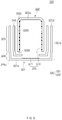
- FIG. 5 is a cross-sectional view of a secondary battery according to a second embodiment of the present invention.
- the secondary battery 200 according to the second embodiment of the present invention may be, for example, a button cell type secondary battery.
- the secondary battery 200 according to the second embodiment of the present invention is different from the secondary battery according to the first embodiment in a structure of a can 220.
- contents of this embodiment which are duplicated with those according to the first embodiment, will be omitted or briefly described, and also, differences therebetween will be mainly described.
- the two metal can half bodies 221 and 222 are separated from each other by an electrical insulation seal (sealant) 240 and form the can 220 having a flat bottom area 223 and a flat upper end area that is parallel to the flat bottom area 223.
- An electrode assembly (electrode separator assembly) 110 comprises at least one positive electrode 111 and at least one negative electrode 112 within the can 220.
- the electrode assembly 110 may be provided in a spiral winding shape, and an end surface of the winding may face a direction of the flat bottom area 223 and the flat upper end area 224.
- Electrode leads 250 and 260 may electrically connect each of at least one positive electrode 111 and at least one negative electrode 112 to one of the can half bodies 221 and 222.
- each of the electrode leads 250 and 260 may be made of a meal material.
- At least one of the electrode leads 250 and 260 may be connected to each of the can half bodies 221 and 222 through welding.
- An insulation coating part 270 is insulation-applied to inner surfaces of the two metal can half bodies 221 and 222.
- the insulation coating part 270 may comprise, for example, a ceramic material that is an insulating material and have a coating thickness of 1 ⁇ m to 15 ⁇ m.
- the insulation coating part 270 may comprise at least one or more of Al 2 O 3 or SiO 2 as the ceramic material.
- the insulation coating part 270 may comprises, for example, Al 2 O 3 .
- the insulation coating part 270 may comprise aluminum oxide (Al 2 O 3 ), an organic binder, an inorganic binder, and alcohol.
- the insulation coating part 270 may comprise 10 wt% to 30 wt% of aluminum oxide (Al 2 O 3 ), 5 wt% to 25 wt% of an organic binder, 10 wt% to 30 wt% of an inorganic binder, and 20 wt% to 35 wt% of alcohol.
- the insulation coating part 270 may comprise SiO 2 as another example.
- the insulation coating part 270 may comprise silicon oxide (SiO 2 ), an organic binder, an inorganic binder, and alcohol.
- the insulation coating part 270 may comprises 10 wt% to 30 wt% of silicon oxide (SiO 2 ), 5 wt% to 25 wt% of an organic binder, 10 wt% to 30 wt% of an inorganic binder, and 20 wt% to 70 wt% of alcohol.
- the insulation coating part 270 may comprise Al 2 O 3 and SiO 2 .
- the insulation coating part 270 may be made of an insulation coating part composition comprising aluminum oxide (Al 2 O 3 ) and silicon dioxide (SiO 2 ).
- the insulation coating part 270 may comprise aluminum oxide (Al 2 O 3 ) as another example and may be made of a composition for the insulation coating part, which comprises aluminum oxide (Al 2 O 3 ), silicon-based rubber, and alcohol.
- the insulation coating part 270 may be made of, for example, a composition for the insulation coating part, which comprises 10 wt% to 30 wt% of aluminum oxide (Al 2 O 3 ), 20 wt% to 50 wt% of silicon-based rubber, and 20 wt% to 70 wt% of alcohol.
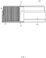
- FIG. 6 is a schematic cross-sectional view of a secondary battery according to a third embodiment of the present invention.
- FIG. 6 is a schematic conceptual view illustrating a secondary battery according to a third embodiment of the present invention.
- an electrode (not shown) is omitted, and a seal 340, a main body 321, and a cover 322 are closely attached to each other so that the inside of a can 320 is sealed.
- the seal 340, the main body 321, and the cover 322 are illustrated as being separated from each other.
- the secondary battery 300 according to the third embodiment of the present invention comprises a thermoplastic film seal 340, a main body 321 and a cover 322, which are connected to each other through the seal 340, and an insulation coating part 370 that is insulation-applied to inner surfaces of the main body 321 and the cover 322.
- the secondary battery 300 according to the third embodiment of the present invention may be, for example, a coin cell type secondary battery.
- the secondary battery 300 according to the third embodiment of the present invention may further comprise an electrode assembly and an electrolyte, which are accommodated in the can 320.
- the main body 321 comprises a base area 321a, a side area 321b, an edge area 321c disposed between the base area 321a and the side area 321b, and a cutting edge 321d.
- the cover 322 comprises a cover area 322a, a side area 322b, an edge area 322c disposed between the cover area 322a and the side area 322b, and a cutting edge 322d.
- the cover 322 may be inserted into the main body 321 so that the side area 322b of the cover 322 and the side area 321b of the main body 321 overlap each other by 20% to 99%.
- an inner radius of the may body 321 may be constant on an area overlapping a direction of the cutting edge 321d.
- At least a portion of the side area 321b of the main body 321, which does not overlap the side area 322b of the cover 322, may be drawn in an inner radial direction so that an outer radius of the side area 321b of the main body 321 on the area 326, which does not overlap the side area 322b of the cover 322, is less than that of the side area 321b of the main body 321 on the overlapping area. That is, in the main body 321, the non-overlapping area 326 may have an outer radius less than that of the overlapping area 325.
- the insulation coating part 370 is insulation-applied to the inner surfaces of the body 321 and the cover 322. That is, the insulation coating part 370 may be formed along the inner surfaces of the can 320 comprising the body 321 and the cover 322.
- the insulation coating part 370 may comprise, for example, an insulation coating part 371 formed along an inner bottom surface of the body 321 and an insulation coating part 372 formed along an inner surface of the cover 322.
- the insulation coating part 370 may comprise, for example, a ceramic material that is an insulating material and have a coating thickness of 1 ⁇ m to 15 ⁇ m.
- the insulation coating part 370 may comprise at least one or more of Al 2 O 3 or SiO 2 as the ceramic material.
- the insulation coating part 370 may comprises, for example, Al 2 O 3 .
- the insulation coating part 370 may comprise aluminum oxide (Al 2 O 3 ), an organic binder, an inorganic binder, and alcohol.
- the insulation coating part 370 may comprise 10 wt% to 30 wt% of aluminum oxide (Al 2 O 3 ), 5 wt% to 25 wt% of an organic binder, 10 wt% to 30 wt% of an inorganic binder, and 20 wt% to 35 wt% of alcohol.
- the insulation coating part 370 may comprise SiO 2 as another example.
- the insulation coating part 370 may comprise silicon oxide (SiO 2 ), an organic binder, an inorganic binder, and alcohol.
- the insulation coating part 370 may comprises 10 wt% to 30 wt% of silicon oxide (SiO 2 ), 5 wt% to 25 wt% of an organic binder, 10 wt% to 30 wt% of an inorganic binder, and 20 wt% to 70 wt% of alcohol.
- the insulation coating part 370 may comprise Al 2 O 3 and SiO 2 .
- the insulation coating part 370 may be made of an insulation coating part composition comprising aluminum oxide (Al 2 O 3 ) and silicon dioxide (SiO 2 ).
- the insulation coating part 370 may comprise aluminum oxide (Al 2 O 3 ) as another example and may be made of a composition for the insulation coating part, which comprises aluminum oxide (Al 2 O 3 ), silicon-based rubber, and alcohol.
- the insulation coating part 370 may be made of, for example, a composition for the insulation coating part, which comprises 10 wt% to 30 wt% of aluminum oxide (Al 2 O 3 ), 20 wt% to 50 wt% of silicon-based rubber, and 20 wt% to 70 wt% of alcohol.
- FIG. 7 is a cross-sectional view of a secondary battery according to a fourth embodiment of the present invention
- FIG. 8 is a cross-sectional view illustrating a main body of the secondary battery according to the fourth embodiment of the present invention
- FIG. 9 is a cross-sectional view illustrating a cover of the secondary battery according to the fourth embodiment of the present invention
- FIG. 10 is a cross-sectional view illustrating the cover and the main body of the secondary battery according to the fourth embodiment of the present invention.
- FIG. 10 illustrates a state in which a main body 421 and a cover 422 respectively move in opposite directions with respect to an axial direction, and a hole 421h formed in the main body 421 is opened when an overpressure occurs inside a can 420.
- a secondary battery 400 according to a fourth embodiment of the present invention comprises the main body 421, the cover 422, a seal 440, and an insulation coating part 470.
- the secondary battery 400 according to the fourth embodiment of the present invention may be, for example, a coin cell type secondary battery.
- the secondary battery 400 according to the fourth embodiment of the present invention may further comprise an electrode assembly 110 and an electrolyte, which are accommodated in the can 420.
- the main body 421 may have a base 421a, a cylindrical casing 421b, an edge portion 421c connecting the base 421a to the casing 421b, and a cutting edge 421d that is curved radially inward so that an inner diameter of the casing 421b of the main body 421 gradually decreases toward the cutting edge 421d.
- at least one hole 421h may pass through a portion of the casing 422b of the main body 421, which overlaps the casing 422b of the cover 422.
- the cover 422 may be inserted into the main body 421 having the cutting edge 421d forward so that the casing 421b of the main body 421 and the casing 422b of the cover 422 at least partially overlap each other, and a portion of the casing 422b is formed in the form of a cylindrical double wall.
- the cover 422 may have a base 422a, a cylindrical casing 422b, an edge portion 422c connecting the base 422a to the casing 422b, and a cutting edge 422d.
- the casing 422b of the cover 422 may comprise a circumferential segment in an area overlapping the case 421b of the main body 421, and the circumferential segment may have an outer radius that is gradually widened outward and greater than an inner diameter of the casing 421b of the main body 421 in a cup edge segment that is curved inward.
- the circumferential segment may be an end segment 422e corresponding to the cutting edge 422d of the cover 422 or a portion that starts from the cutting edge 422d toward the base 422a of the cover 422.
- the cover may comprise an end segment 422e, a second segment 422f, and a stepped segment 422g connecting the end segment 422e to the second segment 422f.
- the seal 440 may be disposed between the main body 421 and the casings 421b and 422b overlapping the cover 422 to separate the main body 421 from the cover 422.
- the main body 421 and the cover 422 may be provided to be movable in opposite directions with respect to an axial direction to dissipate an overpressure within a cell. That is, when the overpressure occurs inside the can 420 comprising the main body 421 and the cover 422 due to an internal gas generation, the main body 421 and the cover 422 may move in the opposite directions with respect to the axial direction to discharge the internal gas to the outside through the hole 421h formed in a side surface of the main body 421.
- the insulation coating part 470 is insulation-applied to the inner surfaces of the body 421 and the cover 422.
- the insulation coating part 470 may comprise, for example, an insulation coating part 471 formed along an inner surface of the body 421 and an insulation coating part 472 formed along an inner surface of the cover 422.
- the insulation coating part 470 may comprise, for example, a ceramic material that is an insulating material and have a coating thickness of 1 ⁇ m to 15 ⁇ m.
- the insulation coating part 470 may comprise at least one or more of Al 2 O 3 or SiO 2 as the ceramic material.
- the insulation coating part 470 may comprises, for example, Al 2 O 3 .
- the insulation coating part 470 may comprise aluminum oxide (Al 2 O 3 ), an organic binder, an inorganic binder, and alcohol.
- the insulation coating part 470 may comprise 10 wt% to 30 wt% of aluminum oxide (Al 2 O 3 ), 5 wt% to 25 wt% of an organic binder, 10 wt% to 30 wt% of an inorganic binder, and 20 wt% to 35 wt% of alcohol.
- the insulation coating part 470 may comprise SiO 2 as another example.
- the insulation coating part 470 may comprise silicon oxide (SiO 2 ), an organic binder, an inorganic binder, and alcohol.
- the insulation coating part 470 may comprises 10 wt% to 30 wt% of silicon oxide (SiO 2 ), 5 wt% to 25 wt% of an organic binder, 10 wt% to 30 wt% of an inorganic binder, and 20 wt% to 70 wt% of alcohol.
- the insulation coating part 470 may comprise Al 2 O 3 and SiO 2 .
- the insulation coating part 470 may be made of an insulation coating part composition comprising aluminum oxide (Al 2 O 3 ) and silicon dioxide (SiO 2 ).
- the insulation coating part 470 may comprise aluminum oxide (Al 2 O 3 ) as another example and may be made of a composition for the insulation coating part, which comprises aluminum oxide (Al 2 O 3 ), silicon-based rubber, and alcohol.
- the insulation coating part 470 may be made of, for example, a composition for the insulation coating part, which comprises 10 wt% to 30 wt% of aluminum oxide (Al 2 O 3 ), 20 wt% to 50 wt% of silicon-based rubber, and 20 wt% to 70 wt% of alcohol.
- a secondary battery was configured to comprise an electrode assembly in which an electrode and a separator are combined and stacked, a can accommodating the electrode assembly therein, and an insulation coating part applied to an inner surface of the can.
- the insulation coating part was formed by applying a coating solution made of a composition for the insulation coating part to the inner surface of the can through a spray coating method.
- aging was performed for 10 minutes in an electric furnace having a temperature of 150°C to form a thin film having a thickness of 10 ⁇ m.
- composition for the insulation coating part was made of 30 wt% of silicon rubber, 12 wt% of Al 2 O 3 powder, 25 wt% of ethanol, and 33 wt% of 2-isopropoxyethanol.
- a secondary battery was configured in the same manner as Embodiment 1 except that an insulation coating part is not formed on an inner surface of a can.
- Insulation was measured in a can.
- Electric current was conducted through 5ea (five secondary batteries) of five secondary batteries, and in Embodiment 1, the insulation was maintained in 5ea (five secondary batteries) of five secondary batteries.
- the can according to Embodiment 1 has insulation properties superior to the can according to Comparative Example 1 through Experimental Examples 1 and 2.
Landscapes
- Chemical & Material Sciences (AREA)
- Chemical Kinetics & Catalysis (AREA)
- Electrochemistry (AREA)
- General Chemical & Material Sciences (AREA)
- Engineering & Computer Science (AREA)
- Manufacturing & Machinery (AREA)
- Inorganic Chemistry (AREA)
- Composite Materials (AREA)
- Materials Engineering (AREA)
- Sealing Battery Cases Or Jackets (AREA)
- Secondary Cells (AREA)
- Connection Of Batteries Or Terminals (AREA)
- Cell Separators (AREA)
Abstract
Description
- The present application claims the benefit of the priority of Korean Patent Application Nos.
10-2018-0095644, filed on August 16, 2018 10-2019-0099301, filed on August 14, 2019 - The present invention relate to a secondary battery.
- Secondary batteries are rechargeable unlike primarily batteries, and also, the possibility of compact size and high capacity is high. Thus, recently, many studies on rechargeable batteries are being carried out. As technology development and demands for mobile devices increase, the demands for rechargeable batteries as energy sources are rapidly increasing.
- Secondary batteries are classified into coin type batteries (button type batteries), cylindrical type batteries, prismatic type batteries, and pouch type batteries according to a shape of a battery case. In such a secondary battery, an electrode assembly mounted in a battery case is a chargeable and dischargeable power generating device having a structure in which an electrode and a separator are stacked.
- It is important that the coin cell type secondary battery has high energy density and high output and also has long lifespan and high stability. That is, studies are being conducted on the coin cell having high voltage characteristics, output characteristics, and high energy density. In particular, it is an important issue to secure a wider accommodating space inside the battery case accommodating the electrode assembly, thereby increasing in energy density.
- One aspect of the prevent invention is to provide a secondary battery that is capable of maximizing an electrode assembly accommodation space within a can.
- A secondary battery according to an embodiment of the present invention comprises an electrode assembly in which an electrode and a separator are combined and staked, a can configured to accommodate the electrode assembly therein, and an insulation coating part that is insulation-applied to an inner surface of the can, wherein the insulation coating part may have a coating thickness of 1 µm to 15 µm.
- According to the present invention, since the insulation coating part is formed inside the can to omit the insulation structure that serves as the insulation part, the accommodation space of the electrode assembly may be maximized, and thus, the energy density may be improved.
-
-
FIG. 1 is a perspective view of a secondary battery according to a first embodiment of the present invention. -
FIG. 2 is an exploded perspective view of an electrode assembly and a can in the secondary battery according to the first embodiment of the present invention. -
FIG. 3 is a cross-sectional view taken along line A-A' ofFIG. 1 . -
FIG. 4 is a cross-sectional view illustrating a main body of the can in the secondary battery according to the first embodiment of the present invention. -
FIG. 5 is a cross-sectional view of a secondary battery according to a second embodiment of the present invention. -
FIG. 6 is a schematic cross-sectional view of a secondary battery according to a third embodiment of the present invention. -
FIG. 7 is a cross-sectional view of a secondary battery according to a fourth embodiment of the present invention. -
FIG. 8 is a cross-sectional view illustrating a main body of the secondary battery according to the fourth embodiment of the present invention. -
FIG. 9 is a cross-sectional view illustrating a cover of the secondary battery according to the fourth embodiment of the present invention. -
FIG. 10 is a cross-sectional view illustrating the cover and the main body of the secondary battery according to the fourth embodiment of the present invention. - The objectives, specific advantages, and novel features of the present invention will become more apparent from the following detailed description taken in conjunction with the accompanying drawings. It should be noted that the reference numerals are added to the components of the drawings in the present specification with the same numerals as possible, even if they are illustrated in other drawings. Also, the present invention may be embodied in different forms and should not be construed as limited to the embodiments set forth herein. In the following description of the present invention, the detailed descriptions of related arts which may unnecessarily obscure the gist of the present invention will be omitted.
-
FIG. 1 is a perspective view of a secondary battery according to a first embodiment of the present invention,FIG. 2 is an exploded perspective view of an electrode assembly and a can in the secondary battery according to the first embodiment of the present invention, andFIG. 3 is a cross-sectional view taken along line A-A' ofFIG. 1 . - Referring to
FIGS. 1 to 3 , asecondary battery 100 according to a first embodiment of the present invention comprises anelectrode assembly 110 in which anelectrode 113 and aseparator 114 are combined (or gathered) to be stacked, a can 120 accommodated in theelectrode assembly 110, and aninsulation coating part 170 that is applied to an inner surface of thecan 120 so as to realize insulation. - Hereinafter, the secondary battery according to the first embodiment of the present invention will be described in more detail with reference to
FIGS. 1 to 4 . - Referring to
FIGS. 2 and3 , theelectrode assembly 110 may be a chargeable and dischargeable power generation element and have a structure in which anelectrode 113 and aseparator 114 are combined and alternately stacked with each other. Here, theelectrode assembly 110 may have a wound shape. However, theelectrode assembly 100 of thesecondary battery 100 according to the embodiment of the present invention is not necessarily limited to the wound shape. For example, theelectrode assembly 100 may have a stack shape in which theelectrode 113 and theseparator 114 are alternately stacked in a plan shape. - The
electrode 113 may comprise afirst electrode 111 and asecond electrode 112. Also, theseparator 114 may separate thefirst electrode 111 from thesecond electrode 112 to insulate the first andsecond electrodes first electrode 111 and the second electrode may be provided in the form of a sheet and then be wound together with theseparator 114 so as to be formed in a jelly roll type. Here, theelectrode assembly 110 may be wound, for example, in a cylindrical shape. Also, theelectrode assembly 110 may have a width w greater than a height h in a winding central axis C direction. Here, the secondary battery according to the first embodiment of the present invention may be applied as a secondary battery having a button cell (coin cell) shape. - For example, the
first electrode 111 may be provided as a positive electrode, and thesecond electrode 112 may be provided as a negative electrode. Here, thefirst electrode 111 may not be necessarily limited to the positive electrode, and thesecond electrode 112 may not be necessarily limited to the negative electrode. For example, thefirst electrode 111 may be provided as a negative electrode, and thesecond electrode 112 may be provided as a positive electrode. - The positive electrode may comprise a positive electrode collector (not shown) and a positive electrode active material (not shown) applied to the positive electrode collector. For example, the positive electrode collector may be provided as foil made of an aluminum material, and the positive electrode active material may be made of lithium manganese oxide, lithium cobalt oxide, lithium nickel oxide, lithium iron phosphate, or a compound or mixture thereof containing at least one or more of the above-described materials.
- The negative electrode may comprise a negative electrode collector (not shown) and a negative electrode active material (not shown) applied to the negative electrode collector. For example, the negative electrode collector may be provided as foil made of a copper (Cu) or nickel (Ni) material. The negative electrode active material may comprise synthetic graphite, lithium a metal, a lithium alloy, carbon, petroleum coke, activated carbon, graphite, a silicon compound, a tin compound, a titanium compound, or an alloy thereof. Here, the negative electrode active material may further comprise, for example, non-graphite-based SiO (silica) or SiC (silicon carbide).
- The
separator 114 may be made of an insulating material, and thefirst electrode 111, theseparator 114, and thesecond electrode 112 may be alternately stacked. Here, theseparator 114 may be disposed between thefirst electrode 111 and the second electrode on outer surfaces of thefirst electrode 111 and thesecond electrode 112. Here, theseparator 114 may be disposed at the outermost side in a width direction W when theelectrode assembly 110 is wound. - Also, the
separator 114 may be made of a flexible material. Here, theseparator 114 may be made of, for example, a polyolefin-based resin film such as polyethylene or polypropylene having micropores. - The
can 120 may accommodate theelectrode assembly 110 therein and have aterminal hole 124 that is opened to one side. - Also, an opening that is opened to one side may be formed in the
can 120. Thecan 120 may comprise amain body 121 comprising anaccommodation part 123 in which theelectrode assembly 110 is accommodated therein and acover 122 covering the opening of themain body 121. Here, theterminal hole 124 passing through thecan 120 may be formed in thecover 122. - Furthermore, the
can 120 may have, for example, a cylindrical shape. - Also, the
can 120 may comprise, for example, a metal material. Here, thecan 120 may comprise, for example, aluminum. - The secondary battery according to the first embodiment of the present invention may further comprise a terminal that electrically connects the
electrode assembly 110 to the outside. Here, the terminal may be provided as arivet terminal 130 having a rivet shape and closes theterminal hole 124 of thecover 122. Here, in the rivet shape, a pillar may be formed in a longitudinal direction, and both ends extend in the width direction W. Here, the longitudinal direction may be, for example, a height direction H as illustrated inFIG. 3 . - Also, the
rivet terminal 130 may comprise acentral portion 131 passing through theterminal hole 124, anouter portion 133 disposed outside thecan 120, and aninner portion 132 disposed inside thecan 120. - The
outer portion 133 and theinner portion 132 may extend in the width direction W of theelectrode assembly 110. Thus, therivet terminal 130 may not be separated from thecover 122 by theouter portion 133 and theinner portion 132. That is, each of a width of theouter portion 133 and a width of theinner portion 132 may be greater than a diameter of theterminal hole 124. Theouter portion 133 and theinner portion 132 may be disposed at both vertical sides of theterminal hole 124 so that therivet terminal 130 is prevented from theterminal hole 124 so as to be firmly coupled to each other. - For example, each of the
outer portion 133 and theinner portion 132 may have a circular plate shape, and thecentral portion 131 may have a cylindrical shape. - Referring to
FIGS. 1 and3 , an outer diameter D2 of theouter portion 133 may be formed to be 80% or less of an outer diameter D1 of thecan 120. Thus, themain body 121 of thecan 120, agasket 140, and therivet terminal 130 may be prevented from interfering with each other. - The gasket 140 (for example, seal) may seal between the
can 120 and therivet terminal 130 to insulate thecan 120 and therivet terminal 130 from each other. Here, thegasket 140 may comprise an electrically insulating and heat-resistant material. - Also, the
gasket 140 may be integrated between thecentral portion 131, theouter portion 133, and theinner portion 132 of therivet terminal 130 and thecover 122. Thus, therivet terminal 130 and thecover 122 of thecan 120 may be firmly coupled to each other to prevent therivet terminal 130 from being connected to thecan 120, thereby providing a safe structure that is capable of preventing electrical short-circuit from occurring. - Both sides of a
first electrode lead 150 may directly contact both sides of thefirst electrode 111 and therivet terminal 130 to electrically connect thefirst electrode 111 to therivet terminal 130. - The
first electrode lead 150 may extend from therivet terminal 130 facing theelectrode assembly 110 along a corresponding surface of theinner portion 132 and thus be connected to theinner portion 132. Here, thefirst electrode lead 150 may be, for example, a positive electrode lead connected to the positive electrode of theelectrode assembly 110. - The
secondary battery 100 according to an embodiment of the present invention may further comprise afirst insulation plate 180 on a top surface of theelectrode assembly 110, which faces thecover 122. Here, thefirst insulation plate 180 may comprise an electrically insulating material. Thus, theelectrode assembly 110 may be electrically connected to thefirst electrode lead 150 or thecover 122 to prevent the short circuit from occurring. - The
second electrode lead 160 may electrically connect thesecond electrode 112 to the can 120 (in particular, electrically connect thesecond electrode 112 to the main body 121). Here, thesecond electrode lead 160 may be, for example, a negative electrode lead connected to the negative electrode of theelectrode assembly 110. -
FIG. 4 is a cross-sectional view illustrating the main body of the can in the secondary battery according to the first embodiment of the present invention. - Referring to
FIGS. 3 and4 , theinsulation coating part 170 may comprise an insulating material so as to be insulation-applied to an inner surface of thecan 120 - Also, the
insulation coating part 170 may comprise a ceramic material that is an insulating material. - Furthermore, the
insulation coating part 170 may comprise at least one or more of Al2O3 or SiO2 as the ceramic material. Thus, theinsulation coating part 170 may realize an insulation effect through a thin coating thickness. - The
insulation coating part 170 may comprises, for example, Al2O3. Thus, theinsulation coating part 170 may comprise Al2O3 that is an insulating material having corrosion resistance and abrasion resistance to prevent thecan 120 from being oxidized. Particularly, when thecan 120 comprises aluminum that is capable of being easily damaged, theinsulation coating part 170 may comprise Al2O3, which has a remarkable effect on the prevention of oxidation of aluminum (Al). Also, theinsulation coating part 170 may comprise Al2O3 having strong abrasion resistance to maintain the insulation without being damaged by abrasion, friction, or an impact. - Here, the
insulation coating part 170 may comprise aluminum oxide (Al2O3), an organic binder, an inorganic binder, and alcohol. Theinsulation coating part 170 may be made of a composition for the insulation coating part, which comprises 10 wt% to 30 wt% of aluminum oxide (Al2O3), 5 wt% to 25 wt% of an organic binder, 10 wt% to 30 wt% of an inorganic binder, and 20 wt% to 35 wt% of alcohol. Thus, theinsulation coating part 170 may have remarkable insulation effect. - Here, the organic binder may be made of at least one or more materials of, for example, acetates, carboxylic acid, or ethers.
- Specifically, the organic binder may be made of at least one or more materials of, for example, dipropyleneglycol monomethyl ether, vinyl acetate, isobuty acetate, or carboxylic acid. More specifically, the carboxylic acid may be selected from the group consisting of, for example, acrylic acid, methacrylic acid, itaconic acid, crotonic acid, fumaric acid, and maleic acid.
- The inorganic binder may be made of at least one or more of, for example, silicate, or boron nitride (BN). The inorganic binder may serve to reinforce the insulating property. Particularly, the inorganic binder may comprise, for example, silicate.
- The alcohol may be made of at least one or more of ethanol, ethyl alcohol, or 2-isopropoxyethanol.
- Also, the
insulation coating part 170 may comprise SiO2 as another example. Thus, theinsulation coating part 170 may comprise SiO2, which is a high heat-resistant material, to insulate theelectrode assembly 110 from thecan 120 without losing the insulation even in a high temperature state when an internal temperature of the battery increases. - The
insulation coating part 170 may be made of a composition for the insulation coating part, which comprises SiO2, an organic binder, an inorganic binder, and alcohol. Here, theinsulation coating part 170 may comprises 10 wt% to 30 wt% of silicon oxide (SiO2), 5 wt% to 25 wt% of an organic binder, 10 wt% to 30 wt% of an inorganic binder, and 20 wt% to 70 wt% of alcohol. Thus, theinsulation coating part 170 may have remarkable insulation effect. In another example of theinsulation coating part 170, the organic binder and the alcohol may be the same as those of the above-described example. In another example of theinsulation coating part 170, the inorganic binder may be made of at least one or more of silicate, aluminum oxide (Al2O3), or boron nitride (BN) . - For another example, the
insulation coating part 170 may comprise Al2O3 and SiO2. - The
insulation coating part 170 may be made of a composition for the insulation coating part, which comprises aluminum oxide (Al2O3) and silicon dioxide (SiO2). Theinsulation coating part 170 may comprise 10 wt% to 30 wt% of aluminum oxide, 20 wt% to 50 wt% of silicon oxide, and 20 wt% to 70 wt% of alcohol. Theinsulation coating part 170 has remarkable insulation and a remarkably excellent electrolyte resistance effect. In another example of theinsulation coating part 170, the alcohol may be the same as that of the above-described example. - Furthermore, the
insulation coating part 170 may comprise aluminum oxide (Al2O3) as another example and may be made of a composition for the insulation coating part, which comprises aluminum oxide (Al2O3), silicon-based rubber, and alcohol. - Here, the
insulation coating part 170 may be made of, for example, a composition for the insulation coating part, which comprises 10 wt% to 30 wt% of aluminum oxide (Al2O3), 20 wt% to 50 wt% of silicon-based rubber, and 20 wt% to 70 wt% of alcohol. Theinsulation coating part 170 has remarkable insulation and a remarkably excellent electrolyte resistance effect. Here, the alcohol may be made of, for example, at least one or more of ethanol, ethyl alcohol, or 2-isopropoxyethanol. More specifically, the alcohol may be made of ethanol and 2-Isopropoxyethanol. - The
insulation coating part 170 may be formed on the inner surface of thecan 120, for example, in the form of a film. - For example, the
insulation coating part 170 may have a coating thickness of 0.5 µm to 30 µm. Particularly, theinsulation coating part 170 may have, for example, a coating thickness of 1 µm to 15 um. Here, theinsulation coating part 170 may have a thickness of 1 µm or more to ensure a thickness at which the insulation effect is capable of being realized. Also, theinsulation coating part 170 may have a thickness 15 µm or less to widely ensure an accommodation space of thecan 120 accommodating theelectrode assembly 110, thereby improving energy density. - For example, the
insulation coating part 170 may be applied to cover an inner surface of thebody 121 of thecan 120. Thus, since an insulation member that insulates theelectrode assembly 110 from thecan 120 may be omitted, the accommodation space of theelectrode assembly 110 may be more widely secured to improve the energy density. Particularly, theinsulation coating part 170 may have a coating thickness of 1 µm to 15 µm to improve the energy density while securing the thickness at which the insulation effect is capable of being realized, thereby significantly increasing in battery capacity. - For another example, the
insulation coating part 170 may be applied to cover inner surfaces of thebody 121 and thecover 122 of thecan 120. - Also, the insulation resistance of the
insulation coating part 170 may be 2 MQ (Mega-Ohm) to 10 MQ, and a melting point of theinsulation coating part 170 may be 800°C to 1500°C. Thus, theinsulation coating part 170 may maximize the insulation effect and the heat resistance effect. - Referring to
FIG. 3 , in thesecondary battery 100 according to the first embodiment of the present invention configured as described above, theinsulation coating part 170 may be formed on the inner surface of thecan 120 to omit the insulation structure that serves as the insulation part, thereby maximizing the accommodation space of theelectrode assembly 110 and also improving the energy density to significantly increase in battery capacity. - Also, the
secondary battery 100 according to the first embodiment of the present invention may have the connection structure using therivet terminal 130 to exclude a connection plate (also called a lower plate and a wide plate-shaped metal plate inserted for easy of welding), etc., thereby increasing in inner space of thecan 120 accommodating theelectrode assembly 110, significantly increasing in energy density, and significantly improving the battery capacity. That is, according to the related art, in the upper terminal structure that connects theelectrode assembly 110 to the outside through the electrode lead, the connection plate for connecting the terminal disposed outside the upper portion of the case to the electrode lead may be used to occupy a large space within the case, thereby deteriorating the energy density. However, In thesecondary battery 100 according to the embodiment of the present invention, the connection structure using therivet terminal 130 may be provided so that theelectrode assembly 110 is disposed in the space in which the connection plate is omitted to significantly increase in energy density. - Hereinafter, a secondary battery according to a second embodiment will be described.
-
FIG. 5 is a cross-sectional view of a secondary battery according to a second embodiment of the present invention. - Referring to
FIG. 5 , asecondary battery 200 according to a second embodiment of the present invention comprises two metal can halfbodies electrode assembly 110 accommodated in thecan 220, electrode leads 250 and 260 electrically connecting theelectrode assembly 110 to thecan half bodies insulation coating part 270 that is insulation-applied to inner surfaces of the two metal can halfbodies secondary battery 200 according to the second embodiment of the present invention may be, for example, a button cell type secondary battery. - The
secondary battery 200 according to the second embodiment of the present invention is different from the secondary battery according to the first embodiment in a structure of acan 220. Thus, contents of this embodiment, which are duplicated with those according to the first embodiment, will be omitted or briefly described, and also, differences therebetween will be mainly described. - In more detail, the two metal can half
bodies can 220 having aflat bottom area 223 and a flat upper end area that is parallel to theflat bottom area 223. - An electrode assembly (electrode separator assembly) 110 comprises at least one
positive electrode 111 and at least onenegative electrode 112 within thecan 220. - Also, the
electrode assembly 110 may be provided in a spiral winding shape, and an end surface of the winding may face a direction of theflat bottom area 223 and the flatupper end area 224. - Electrode leads 250 and 260 may electrically connect each of at least one
positive electrode 111 and at least onenegative electrode 112 to one of thecan half bodies - Also, at least one of the electrode leads 250 and 260 may be connected to each of the
can half bodies - An
insulation coating part 270 is insulation-applied to inner surfaces of the two metal can halfbodies - Also, the
insulation coating part 270 may comprise, for example, a ceramic material that is an insulating material and have a coating thickness of 1 µm to 15 µm. - Furthermore, the
insulation coating part 270 may comprise at least one or more of Al2O3 or SiO2 as the ceramic material. - The
insulation coating part 270 may comprises, for example, Al2O3. Here, theinsulation coating part 270 may comprise aluminum oxide (Al2O3), an organic binder, an inorganic binder, and alcohol. Theinsulation coating part 270 may comprise 10 wt% to 30 wt% of aluminum oxide (Al2O3), 5 wt% to 25 wt% of an organic binder, 10 wt% to 30 wt% of an inorganic binder, and 20 wt% to 35 wt% of alcohol. - Also, the
insulation coating part 270 may comprise SiO2 as another example. Here, theinsulation coating part 270 may comprise silicon oxide (SiO2), an organic binder, an inorganic binder, and alcohol. Here, theinsulation coating part 270 may comprises 10 wt% to 30 wt% of silicon oxide (SiO2), 5 wt% to 25 wt% of an organic binder, 10 wt% to 30 wt% of an inorganic binder, and 20 wt% to 70 wt% of alcohol. - For another example, the
insulation coating part 270 may comprise Al2O3 and SiO2. Theinsulation coating part 270 may be made of an insulation coating part composition comprising aluminum oxide (Al2O3) and silicon dioxide (SiO2). - Furthermore, the
insulation coating part 270 may comprise aluminum oxide (Al2O3) as another example and may be made of a composition for the insulation coating part, which comprises aluminum oxide (Al2O3), silicon-based rubber, and alcohol. Here, theinsulation coating part 270 may be made of, for example, a composition for the insulation coating part, which comprises 10 wt% to 30 wt% of aluminum oxide (Al2O3), 20 wt% to 50 wt% of silicon-based rubber, and 20 wt% to 70 wt% of alcohol. - Hereinafter, a secondary battery according to a third embodiment will be described.
-
FIG. 6 is a schematic cross-sectional view of a secondary battery according to a third embodiment of the present invention. Here,FIG. 6 is a schematic conceptual view illustrating a secondary battery according to a third embodiment of the present invention. Thus, an electrode (not shown) is omitted, and aseal 340, amain body 321, and acover 322 are closely attached to each other so that the inside of acan 320 is sealed. However, for convenience of description, theseal 340, themain body 321, and thecover 322 are illustrated as being separated from each other. - Referring to
FIG. 6 , thesecondary battery 300 according to the third embodiment of the present invention comprises athermoplastic film seal 340, amain body 321 and acover 322, which are connected to each other through theseal 340, and aninsulation coating part 370 that is insulation-applied to inner surfaces of themain body 321 and thecover 322. Here, thesecondary battery 300 according to the third embodiment of the present invention may be, for example, a coin cell type secondary battery. Also, thesecondary battery 300 according to the third embodiment of the present invention may further comprise an electrode assembly and an electrolyte, which are accommodated in thecan 320. - In more detail, the
main body 321 comprises abase area 321a, aside area 321b, anedge area 321c disposed between thebase area 321a and theside area 321b, and acutting edge 321d. - The
cover 322 comprises acover area 322a, aside area 322b, anedge area 322c disposed between thecover area 322a and theside area 322b, and acutting edge 322d. - The
cover 322 may be inserted into themain body 321 so that theside area 322b of thecover 322 and theside area 321b of themain body 321 overlap each other by 20% to 99%. Here, an inner radius of themay body 321 may be constant on an area overlapping a direction of thecutting edge 321d. - At least a portion of the
side area 321b of themain body 321, which does not overlap theside area 322b of thecover 322, may be drawn in an inner radial direction so that an outer radius of theside area 321b of themain body 321 on thearea 326, which does not overlap theside area 322b of thecover 322, is less than that of theside area 321b of themain body 321 on the overlapping area. That is, in themain body 321, thenon-overlapping area 326 may have an outer radius less than that of the overlappingarea 325. - The
insulation coating part 370 is insulation-applied to the inner surfaces of thebody 321 and thecover 322. That is, theinsulation coating part 370 may be formed along the inner surfaces of thecan 320 comprising thebody 321 and thecover 322. Here, theinsulation coating part 370 may comprise, for example, aninsulation coating part 371 formed along an inner bottom surface of thebody 321 and aninsulation coating part 372 formed along an inner surface of thecover 322. - Also, the
insulation coating part 370 may comprise, for example, a ceramic material that is an insulating material and have a coating thickness of 1 µm to 15 µm. - Furthermore, the
insulation coating part 370 may comprise at least one or more of Al2O3 or SiO2 as the ceramic material. - The
insulation coating part 370 may comprises, for example, Al2O3. Here, theinsulation coating part 370 may comprise aluminum oxide (Al2O3), an organic binder, an inorganic binder, and alcohol. Theinsulation coating part 370 may comprise 10 wt% to 30 wt% of aluminum oxide (Al2O3), 5 wt% to 25 wt% of an organic binder, 10 wt% to 30 wt% of an inorganic binder, and 20 wt% to 35 wt% of alcohol. - Also, the
insulation coating part 370 may comprise SiO2 as another example. Here, theinsulation coating part 370 may comprise silicon oxide (SiO2), an organic binder, an inorganic binder, and alcohol. Here, theinsulation coating part 370 may comprises 10 wt% to 30 wt% of silicon oxide (SiO2), 5 wt% to 25 wt% of an organic binder, 10 wt% to 30 wt% of an inorganic binder, and 20 wt% to 70 wt% of alcohol. - For another example, the
insulation coating part 370 may comprise Al2O3 and SiO2. Theinsulation coating part 370 may be made of an insulation coating part composition comprising aluminum oxide (Al2O3) and silicon dioxide (SiO2). - Furthermore, the
insulation coating part 370 may comprise aluminum oxide (Al2O3) as another example and may be made of a composition for the insulation coating part, which comprises aluminum oxide (Al2O3), silicon-based rubber, and alcohol. Here, theinsulation coating part 370 may be made of, for example, a composition for the insulation coating part, which comprises 10 wt% to 30 wt% of aluminum oxide (Al2O3), 20 wt% to 50 wt% of silicon-based rubber, and 20 wt% to 70 wt% of alcohol. - Hereinafter, a secondary battery according to a fourth embodiment will be described.
-
FIG. 7 is a cross-sectional view of a secondary battery according to a fourth embodiment of the present invention,FIG. 8 is a cross-sectional view illustrating a main body of the secondary battery according to the fourth embodiment of the present invention,FIG. 9 is a cross-sectional view illustrating a cover of the secondary battery according to the fourth embodiment of the present invention, andFIG. 10 is a cross-sectional view illustrating the cover and the main body of the secondary battery according to the fourth embodiment of the present invention. Here,FIG. 10 illustrates a state in which amain body 421 and acover 422 respectively move in opposite directions with respect to an axial direction, and ahole 421h formed in themain body 421 is opened when an overpressure occurs inside acan 420. - Referring to
FIGS. 7 to 10 , asecondary battery 400 according to a fourth embodiment of the present invention comprises themain body 421, thecover 422, aseal 440, and aninsulation coating part 470. Here, thesecondary battery 400 according to the fourth embodiment of the present invention may be, for example, a coin cell type secondary battery. Here, thesecondary battery 400 according to the fourth embodiment of the present invention may further comprise anelectrode assembly 110 and an electrolyte, which are accommodated in thecan 420. - In more detail, the
main body 421 may have abase 421a, acylindrical casing 421b, anedge portion 421c connecting thebase 421a to thecasing 421b, and acutting edge 421d that is curved radially inward so that an inner diameter of thecasing 421b of themain body 421 gradually decreases toward thecutting edge 421d. Also, at least onehole 421h may pass through a portion of thecasing 422b of themain body 421, which overlaps thecasing 422b of thecover 422. - The
cover 422 may be inserted into themain body 421 having thecutting edge 421d forward so that thecasing 421b of themain body 421 and thecasing 422b of thecover 422 at least partially overlap each other, and a portion of thecasing 422b is formed in the form of a cylindrical double wall. - The
cover 422 may have abase 422a, acylindrical casing 422b, anedge portion 422c connecting thebase 422a to thecasing 422b, and acutting edge 422d. Here, thecasing 422b of thecover 422 may comprise a circumferential segment in an area overlapping thecase 421b of themain body 421, and the circumferential segment may have an outer radius that is gradually widened outward and greater than an inner diameter of thecasing 421b of themain body 421 in a cup edge segment that is curved inward. - The circumferential segment may be an
end segment 422e corresponding to thecutting edge 422d of thecover 422 or a portion that starts from thecutting edge 422d toward thebase 422a of thecover 422. - The cover may comprise an
end segment 422e, asecond segment 422f, and a steppedsegment 422g connecting theend segment 422e to thesecond segment 422f. - The
seal 440 may be disposed between themain body 421 and thecasings cover 422 to separate themain body 421 from thecover 422. - The
main body 421 and thecover 422 may be provided to be movable in opposite directions with respect to an axial direction to dissipate an overpressure within a cell. That is, when the overpressure occurs inside thecan 420 comprising themain body 421 and thecover 422 due to an internal gas generation, themain body 421 and thecover 422 may move in the opposite directions with respect to the axial direction to discharge the internal gas to the outside through thehole 421h formed in a side surface of themain body 421. - The
insulation coating part 470 is insulation-applied to the inner surfaces of thebody 421 and thecover 422. - Also, the
insulation coating part 470 may comprise, for example, aninsulation coating part 471 formed along an inner surface of thebody 421 and aninsulation coating part 472 formed along an inner surface of thecover 422. - Also, the
insulation coating part 470 may comprise, for example, a ceramic material that is an insulating material and have a coating thickness of 1 µm to 15 µm. - Furthermore, the
insulation coating part 470 may comprise at least one or more of Al2O3 or SiO2 as the ceramic material. - The
insulation coating part 470 may comprises, for example, Al2O3. Here, theinsulation coating part 470 may comprise aluminum oxide (Al2O3), an organic binder, an inorganic binder, and alcohol. Theinsulation coating part 470 may comprise 10 wt% to 30 wt% of aluminum oxide (Al2O3), 5 wt% to 25 wt% of an organic binder, 10 wt% to 30 wt% of an inorganic binder, and 20 wt% to 35 wt% of alcohol. - Also, the
insulation coating part 470 may comprise SiO2 as another example. Here, theinsulation coating part 470 may comprise silicon oxide (SiO2), an organic binder, an inorganic binder, and alcohol. Here, theinsulation coating part 470 may comprises 10 wt% to 30 wt% of silicon oxide (SiO2), 5 wt% to 25 wt% of an organic binder, 10 wt% to 30 wt% of an inorganic binder, and 20 wt% to 70 wt% of alcohol. - For another example, the
insulation coating part 470 may comprise Al2O3 and SiO2. Theinsulation coating part 470 may be made of an insulation coating part composition comprising aluminum oxide (Al2O3) and silicon dioxide (SiO2). - Furthermore, the
insulation coating part 470 may comprise aluminum oxide (Al2O3) as another example and may be made of a composition for the insulation coating part, which comprises aluminum oxide (Al2O3), silicon-based rubber, and alcohol. Here, theinsulation coating part 470 may be made of, for example, a composition for the insulation coating part, which comprises 10 wt% to 30 wt% of aluminum oxide (Al2O3), 20 wt% to 50 wt% of silicon-based rubber, and 20 wt% to 70 wt% of alcohol. - A secondary battery was configured to comprise an electrode assembly in which an electrode and a separator are combined and stacked, a can accommodating the electrode assembly therein, and an insulation coating part applied to an inner surface of the can.
- Also, the insulation coating part was formed by applying a coating solution made of a composition for the insulation coating part to the inner surface of the can through a spray coating method. Here, aging was performed for 10 minutes in an electric furnace having a temperature of 150°C to form a thin film having a thickness of 10 µm.
- The composition for the insulation coating part was made of 30 wt% of silicon rubber, 12 wt% of Al2O3 powder, 25 wt% of ethanol, and 33 wt% of 2-isopropoxyethanol.
- A secondary battery was configured in the same manner as Embodiment 1 except that an insulation coating part is not formed on an inner surface of a can.
- Insulation was measured in a can. Here, in Comparative Example 1, electric current was conducted through 5ea (five secondary batteries) of five secondary batteries, and in Embodiment 1, the insulation was maintained in 5ea (five secondary batteries) of five secondary batteries.
- After a ramp-up test (test for checking while rising a temperature) is performed up to a temperature of 130°C, the retention of the insulating coating was confirmed. Here, in Comparative Example 1, electric current was conducted through 5ea (five secondary batteries) of five secondary batteries, and thus, there was no insulation properties, and in Embodiment 1, the insulation effect was maintained in 10ea (ten secondary batteries) of ten secondary batteries.
- As a result, it may be seen that the can according to Embodiment 1 has insulation properties superior to the can according to Comparative Example 1 through Experimental Examples 1 and 2.
- While the present invention has been particularly shown and described with reference to exemplary embodiments thereof, it is to be understood that the scope of the present invention is not limited to the secondary battery according to the present invention. It will be understood by those of ordinary skill in the art that various changes in form and details may be made therein without departing from the spirit and scope of the invention.
- Furthermore, the scope of protection of the present invention will be clarified by the appended claims.
Claims (16)
- A secondary battery comprising:an electrode assembly in which an electrode and a separator are combined and staked;a can configured to accommodate the electrode assembly therein; andan insulation coating part that is insulation-applied to an inner surface of the can,wherein the insulation coating part comprises a ceramic material and has a coating thickness of 1 µm to 15 µm.
- The secondary battery of claim 1, wherein the insulation coating part comprises at least one or more of Al2O3 or SiO2.
- The secondary battery of claim 1, wherein the insulation coating part is made of a composition for the insulation coating part, which comprises aluminum oxide (Al2O3), an organic binder, an inorganic binder, and alcohol.
- The secondary battery of claim 3, wherein the inorganic binder is made of at least one or more of silicate or boron nitride (BN).
- The secondary battery of claim 1, wherein the insulation coating part is made of a composition for the insulation coating part, which comprises silicon dioxide (SiO 2), an organic binder, an inorganic binder, and alcohol.
- The secondary battery of claim 5, wherein the inorganic binder is made of at least one or more of silicate, aluminum oxide (Al2O3), or boron nitride (BN) .
- The secondary battery of claim 3 or 5, wherein the organic binder is made of at least one or more materials of acetates, carboxylic acid, or ethers.
- The secondary battery of claim 3 or 5, wherein the organic binder is made of at least one or more materials of dipropyleneglycol monomethyl ether, vinyl acetate, isobuty acetate, or carboxylic acid.
- The secondary battery of claim 1, wherein the insulation coating part is made of a composition for the insulation coating part, which comprises aluminum oxide (Al2O3), silicon-based rubber, and alcohol.
- The secondary battery of any one of claims 3, 5, and 8, wherein the alcohol is made of at least one or more of ethanol, ethyl alcohol, or 2-isopropoxyethanol.
- The secondary battery of claim 1, wherein the electrode assembly has a cylindrical shape in which the electrode and the separator are wound, and the can has a cylindrical shape,
the can comprises an opening with one side opened, a main body having an accommodation part configured to accommodate the electrode assembly, and a cover configured to cover the opening, and
the electrode assembly has a with (w) greater than a height (h) in a direction of a winding central axis (c). - The secondary battery of claim 11, wherein the insulation coating part is applied to cover an inner surface of the main body.
- The secondary battery of claim 1, wherein insulation resistance of the insulation coating part is 2 MQ (Mega-Ohm) to 10 MQ, and a melting point of the insulation coating part is 800°C to 1500°C.
- A secondary battery comprising:two metal can half bodies, which are separated from each other by an electrical insulation seal and form a can having a flat bottom area and a flat upper end area that is parallel to the flat bottom area;an electrode assembly comprising at least one positive electrode and at least one negative electrode within the can, wherein the electrode assembly is provided in a spiral winding shape, and an end surface of the winding faces a direction of the flat bottom area and the flat upper end area;electrode leads configured to electrically connect each of the at least one positive electrode and the at least one negative electrode to one of the can half bodies; andan insulation coating part that is insulation-applied to inner surfaces of the two metal can half bodies,wherein the insulation coating part comprises a ceramic material and has a coating thickness of 1 µm to 15 µm, andat least one of the electrode leads is connected to each of the can half bodies through welding.
- A secondary battery having a can with no flange, comprising:a main body and a cover, which are connected to each other through a thermoplastic film seal,wherein the main body comprises a base area, a side area, an edge area disposed between the base area and the side area, and a cutting edge,the cover comprises a cover area, a side area, an edge area disposed between the cover area and the side area, and a cutting edge,the cover is inserted into the main body so that the side area of the cover and the side area of the main body overlap each other by 20% to 99%, and an inner radius of the may body is constant on an area overlapping a direction of the cutting edge, andat least a portion of the side area of the main body, which does not overlap the side area of the cover, is drawn in an inner radial direction so that an outer radius of the side area of the main body on the area, which does not overlap the side area of the cover, is less than that of the side area of the main body on the overlapping area; andan insulation coating part that is insulation-applied to inner surfaces of the main body and the cover,wherein the insulation coating part comprises a ceramic material and has a coating thickness of 1 µm to 15 µm.
- A secondary battery having a can that is closed to prevent a liquid from leaking, the secondary battery comprising:a main body, a cover, and a seal,wherein the main body has a base, a cylindrical casing, an edge portion configured to connect the base to the casing, and a cutting edge that is curved radially inward so that an inner diameter of the casing of the main body gradually decreases toward the cutting edge,the cover is inserted into the main body having the cutting edge forward so that the casing of the main body and a casing of the cover at least partially overlap each other, and a portion of the casing is formed in the form of a cylindrical double wall,the cover has a base, a cylindrical casing, an edge portion configured to connect the base to the casing, and a cutting edge, wherein the casing of the cover comprises a circumferential segment in an area overlapping the case of the main body, and the circumferential segment has an outer radius that is gradually widened outward and greater than an inner diameter of the casing of the main body in a cup edge segment that is curved inward,the circumferential segment is an end segment corresponding to the cutting edge of the cover or a portion that starts from the cutting edge toward the base of the cover,the seal is disposed between the main body and the casing overlapping the cover to separate the main body from the cover,at least one hole passes through a portion of the casing of the main body, which overlaps the casing of the cover,the main body and the cover are movable in opposite dir ections with respect to an axial direction to dissipate an ov erpressure within a cell,an insulation coating part that is insulation-applied is formed on inner surfaces of the main body and the cover, andthe insulation coating part comprises a ceramic material and has a coating thickness of 1 µm to 15 µm.
Applications Claiming Priority (2)
| Application Number | Priority Date | Filing Date | Title |
|---|---|---|---|
| KR20180095644 | 2018-08-16 | ||
| PCT/KR2019/010374 WO2020036440A1 (en) | 2018-08-16 | 2019-08-14 | Secondary battery |
Publications (2)
| Publication Number | Publication Date |
|---|---|
| EP3823058A1 true EP3823058A1 (en) | 2021-05-19 |
| EP3823058A4 EP3823058A4 (en) | 2021-09-22 |
Family
ID=69637870
Family Applications (1)
| Application Number | Title | Priority Date | Filing Date |
|---|---|---|---|
| EP19850306.2A Pending EP3823058A4 (en) | 2018-08-16 | 2019-08-14 | SECONDARY BATTERY |
Country Status (5)
| Country | Link |
|---|---|
| US (1) | US12224446B2 (en) |
| EP (1) | EP3823058A4 (en) |
| JP (1) | JP7102674B2 (en) |
| KR (1) | KR102512119B1 (en) |
| CN (1) | CN112771710B (en) |
Cited By (1)
| Publication number | Priority date | Publication date | Assignee | Title |
|---|---|---|---|---|
| WO2024061545A1 (en) * | 2022-09-19 | 2024-03-28 | Mercedes-Benz Group AG | Housing for an individual battery cell |
Families Citing this family (41)
| Publication number | Priority date | Publication date | Assignee | Title |
|---|---|---|---|---|
| WO2020097174A1 (en) * | 2018-11-07 | 2020-05-14 | Rutgers, The State University Of New Jersey | Enclosures for electrochemical cells |
| KR102864764B1 (en) * | 2019-08-19 | 2025-09-24 | 삼성에스디아이 주식회사 | Rechargeable battery |
| JP1663323S (en) * | 2020-01-15 | 2020-07-13 | ||
| JP1679817S (en) * | 2020-01-15 | 2021-02-22 | ||
| TWI900540B (en) | 2020-03-11 | 2025-10-11 | 南韓商Lg新能源股份有限公司 | Button type secondary battery |
| KR102907169B1 (en) * | 2020-04-29 | 2025-12-31 | 삼성에스디아이 주식회사 | Rechargeable battery |
| CN113826268A (en) * | 2020-05-18 | 2021-12-21 | 宁德新能源科技有限公司 | Battery and electrical device having the same |
| CN111682129A (en) * | 2020-06-05 | 2020-09-18 | 重庆市紫建电子股份有限公司 | A metal shell button lithium ion battery |
| KR102927442B1 (en) * | 2020-06-18 | 2026-02-12 | 삼성에스디아이 주식회사 | Secondary battery |
| KR20210158162A (en) * | 2020-06-23 | 2021-12-30 | 삼성에스디아이 주식회사 | Secondary battery |
| KR102927441B1 (en) * | 2020-06-23 | 2026-02-12 | 삼성에스디아이 주식회사 | Secondary battery |
| KR20220003395A (en) * | 2020-07-01 | 2022-01-10 | 삼성에스디아이 주식회사 | Rechargeable battery |
| KR20220008685A (en) * | 2020-07-14 | 2022-01-21 | 주식회사 엘지에너지솔루션 | Button type secondary battery |
| CN115398723B (en) | 2020-07-29 | 2024-08-06 | 株式会社Lg新能源 | Button secondary battery and method for manufacturing same |
| KR102838322B1 (en) | 2020-07-31 | 2025-07-24 | 주식회사 엘지에너지솔루션 | Button-type secondary battery |
| CN111834558B (en) * | 2020-08-10 | 2024-05-07 | 惠州亿纬锂能股份有限公司 | An electronic device and a method for manufacturing the same |
| US12592438B2 (en) | 2020-08-10 | 2026-03-31 | Eve Energy Co., Ltd. | Electronic device and manufacturing method therefor |
| CN114930620B (en) * | 2020-09-16 | 2024-08-06 | 株式会社Lg新能源 | Button type secondary battery |
| CN114902487B (en) * | 2020-09-18 | 2024-11-05 | 株式会社Lg新能源 | Button type secondary battery |
| US12506233B2 (en) | 2020-09-18 | 2025-12-23 | Lg Energy Solution, Ltd. | Button-type secondary battery |
| KR20220105018A (en) * | 2021-01-19 | 2022-07-26 | 삼성에스디아이 주식회사 | Rechargeable battery |
| KR102824727B1 (en) * | 2021-01-29 | 2025-06-25 | 주식회사 엘지에너지솔루션 | Button type secondary battery |
| KR102986374B1 (en) * | 2021-02-19 | 2026-07-02 | 삼성에스디아이 주식회사 | Rechargeable battery |
| CN113131049B (en) * | 2021-04-30 | 2024-11-22 | 国研新能(深圳)技术有限公司 | Battery case and battery |
| KR102954921B1 (en) * | 2021-07-12 | 2026-04-20 | 주식회사 엘지에너지솔루션 | Button type secondary battery |
| US11605851B1 (en) * | 2021-09-21 | 2023-03-14 | Knoetik Solutions, Inc. | Systems, methods and apparatus for improving rechargeable energy storage devices and integrated circuits |
| KR102978490B1 (en) * | 2021-10-14 | 2026-06-16 | 주식회사 엘지에너지솔루션 | Button type secondary battery |
| KR102914734B1 (en) | 2021-10-14 | 2026-01-19 | 주식회사 엘지에너지솔루션 | Button type secondary battery |
| CN218827726U (en) * | 2021-10-22 | 2023-04-07 | 株式会社Lg新能源 | Cylindrical battery and its battery pack and automobile |
| US20240274982A1 (en) * | 2021-11-19 | 2024-08-15 | Lg Energy Solution, Ltd. | Secondary battery, and battery pack and vehicle comprising same |
| KR102577169B1 (en) * | 2021-12-02 | 2023-09-11 | 삼성에스디아이 주식회사 | Cylindrical secondary battery |
| KR102702547B1 (en) * | 2022-02-07 | 2024-09-05 | 삼성에스디아이 주식회사 | Cylindrical secondary battery |
| KR102972661B1 (en) * | 2022-02-28 | 2026-06-04 | 주식회사 엘지에너지솔루션 | Cylindrical secondary battery, and battery pack and vehicle including the same |
| CN220627729U (en) | 2022-06-27 | 2024-03-19 | 米沃奇电动工具公司 | Fuses and devices including conductive paths for the passage of electric current |
| EP4379938A4 (en) * | 2022-10-17 | 2025-03-12 | Contemporary Amperex Technology (Hong Kong) Limited | Electrode assembly, battery cell, battery and electric device |
| WO2024262874A1 (en) * | 2023-06-23 | 2024-12-26 | 주식회사 엘지에너지솔루션 | Battery cell, battery pack and vehicle comprising same |
| KR102950675B1 (en) * | 2023-07-13 | 2026-04-09 | 삼성에스디아이 주식회사 | Cylindrical secondary battery |
| KR102890321B1 (en) * | 2024-08-29 | 2025-11-24 | 비나텍 주식회사 | Cylindrical energy storage device |
| CN223285090U (en) * | 2024-09-24 | 2025-08-29 | 惠州亿纬锂能股份有限公司 | Cover assembly, micro battery and capsule endoscope |
| WO2026126011A1 (en) * | 2024-12-11 | 2026-06-18 | Ola Electric Mobility Limited | A cell assembly and a method for manufacturing the cell assembly |
| CN121097282A (en) * | 2025-08-01 | 2025-12-09 | 蜂巢能源科技股份有限公司 | Housing, battery and power utilization device |
Family Cites Families (25)
| Publication number | Priority date | Publication date | Assignee | Title |
|---|---|---|---|---|
| KR19980019615U (en) | 1996-10-04 | 1998-07-15 | 손욱 | Cylindrical battery |
| JP2000106215A (en) * | 1998-09-30 | 2000-04-11 | Japan Storage Battery Co Ltd | Non-aqueous electrolyte battery |
| JP2001023608A (en) | 1999-07-12 | 2001-01-26 | Matsushita Electric Ind Co Ltd | Rechargeable battery |
| JP2005278353A (en) * | 2004-03-26 | 2005-10-06 | Mitsubishi Electric Corp | Electric motor |
| KR100648731B1 (en) | 2005-03-21 | 2006-11-23 | 삼성에스디아이 주식회사 | Secondary Battery and Manufacturing Method Thereof |
| KR101156964B1 (en) * | 2007-01-06 | 2012-06-20 | 주식회사 엘지화학 | Secondary Battery Comprising Battery Case Coated Inside with Insulating Material |
| WO2009123888A1 (en) | 2008-04-02 | 2009-10-08 | Powergenix Systems, Inc. | Cylindrical nickel-zinc cell with negative can |
| KR20090106841A (en) * | 2008-04-07 | 2009-10-12 | 삼성에스디아이 주식회사 | Electrode assembly and secondary battery having same |
| CN102232251B (en) * | 2008-10-07 | 2014-11-19 | 江森自控帅福得先进能源动力系统有限责任公司 | Electrochemical cell having an electrically-insulated housing |
| KR100985521B1 (en) | 2009-03-31 | 2010-10-05 | 이정용 | Battery stack assembly |
| KR101036062B1 (en) | 2008-12-11 | 2011-05-19 | 삼성에스디아이 주식회사 | Secondary battery |
| DE102009060800A1 (en) * | 2009-06-18 | 2011-06-09 | Varta Microbattery Gmbh | Button cell with winding electrode and method for its production |
| DE102010042548A1 (en) | 2010-10-16 | 2012-04-19 | Varta Microbattery Gmbh | Button cell with burst protection |
| WO2013136426A1 (en) * | 2012-03-13 | 2013-09-19 | 株式会社日立製作所 | Non-aqueous electrolyte secondary battery and method for producing same |
| JP5995469B2 (en) | 2012-03-14 | 2016-09-21 | セイコーインスツル株式会社 | Coin-type non-aqueous electrolyte secondary battery and method for producing coin-type non-aqueous electrolyte secondary battery |
| KR101684283B1 (en) | 2014-07-18 | 2016-12-08 | 주식회사 엘지화학 | Jelly-roll type electrode assembly |
| KR101781680B1 (en) * | 2014-12-02 | 2017-09-25 | 한양대학교 산학협력단 | flexible and stretchable piezoelectronic fiber and fabrication method thereof |
| US9620830B2 (en) * | 2014-12-16 | 2017-04-11 | Xinen Technology Hong Kong Company, Ltd. | Vehicle battery module with cooling and safety features |
| KR101827050B1 (en) | 2015-01-30 | 2018-02-07 | 주식회사 엘지화학 | Li-ion Battery |
| CN113871764A (en) | 2015-06-10 | 2021-12-31 | 凸版印刷株式会社 | Exterior member for secondary battery |
| JP2017028018A (en) | 2015-07-17 | 2017-02-02 | 株式会社神戸製鋼所 | Heat dissipation board, device, and method of manufacturing heat dissipation board |
| KR102467002B1 (en) | 2015-11-24 | 2022-11-11 | 삼성에스디아이 주식회사 | Rechargeable battery |
| JP6788991B2 (en) * | 2016-04-12 | 2020-11-25 | 昭和電工パッケージング株式会社 | Exterior material for power storage device and power storage device |
| KR20180040334A (en) * | 2016-10-12 | 2018-04-20 | 삼성에스디아이 주식회사 | Negative electrode for rechargeable lithium battery and rechargeable lithium battery including the same |
| CN106450498A (en) | 2016-12-28 | 2017-02-22 | 珠海市至力电池有限公司 | Encapsulation type rechargeable lithium ion button battery |
-
2019
- 2019-08-14 US US17/268,125 patent/US12224446B2/en active Active
- 2019-08-14 EP EP19850306.2A patent/EP3823058A4/en active Pending
- 2019-08-14 JP JP2021501276A patent/JP7102674B2/en active Active
- 2019-08-14 KR KR1020190099301A patent/KR102512119B1/en active Active
- 2019-08-14 CN CN201980053582.0A patent/CN112771710B/en active Active
Cited By (1)
| Publication number | Priority date | Publication date | Assignee | Title |
|---|---|---|---|---|
| WO2024061545A1 (en) * | 2022-09-19 | 2024-03-28 | Mercedes-Benz Group AG | Housing for an individual battery cell |
Also Published As
| Publication number | Publication date |
|---|---|
| US20210328290A1 (en) | 2021-10-21 |
| JP7102674B2 (en) | 2022-07-20 |
| CN112771710B (en) | 2024-06-18 |
| US12224446B2 (en) | 2025-02-11 |
| CN112771710A (en) | 2021-05-07 |
| EP3823058A4 (en) | 2021-09-22 |
| KR102512119B1 (en) | 2023-03-22 |
| KR20200020619A (en) | 2020-02-26 |
| JP2021530843A (en) | 2021-11-11 |
Similar Documents
| Publication | Publication Date | Title |
|---|---|---|
| US12224446B2 (en) | Secondary battery | |
| CN112262491B (en) | Secondary battery | |
| KR102622370B1 (en) | Rechargeable battery | |
| EP4270565A1 (en) | Electrode assembly and secondary battery comprising same | |
| KR101629499B1 (en) | Electrode assembly and secondary battery comprising the same | |
| EP4037068A1 (en) | Electrode assembly and secondary battery comprising same | |
| KR20230074007A (en) | Secondary battery, battery pack comprising same and vehicle | |
| CN115699434A (en) | secondary battery | |
| KR102930302B1 (en) | Button type rechargeable battery | |
| KR102943877B1 (en) | Lithium rechargeable battery and lithium rechargeable battery manufacturing method | |
| KR100947977B1 (en) | Secondary battery | |
| KR102886046B1 (en) | Electrode assembly and rechargeable battery comprising the same | |
| US11742541B2 (en) | Secondary battery | |
| KR20190083130A (en) | Electrode assembly for coin cell and coin cell comprising the same | |
| KR102896837B1 (en) | Button type rechargeable battery | |
| KR20250020158A (en) | Electrode assembly, secondary battery, battery pack and vehicle | |
| KR20250049622A (en) | Electrode assembly, second battery comprising same, battery pack and vehicle | |
| KR20250019310A (en) | Electrode assembly, secondary battery, battery pack and vehicle |
Legal Events
| Date | Code | Title | Description |
|---|---|---|---|
| STAA | Information on the status of an ep patent application or granted ep patent |
Free format text: STATUS: THE INTERNATIONAL PUBLICATION HAS BEEN MADE |
|
| PUAI | Public reference made under article 153(3) epc to a published international application that has entered the european phase |
Free format text: ORIGINAL CODE: 0009012 |
|
| STAA | Information on the status of an ep patent application or granted ep patent |
Free format text: STATUS: REQUEST FOR EXAMINATION WAS MADE |
|
| 17P | Request for examination filed |
Effective date: 20210212 |
|
| AK | Designated contracting states |
Kind code of ref document: A1 Designated state(s): AL AT BE BG CH CY CZ DE DK EE ES FI FR GB GR HR HU IE IS IT LI LT LU LV MC MK MT NL NO PL PT RO RS SE SI SK SM TR |
|
| REG | Reference to a national code |
Ref country code: DE Ref legal event code: R079 Free format text: PREVIOUS MAIN CLASS: H01M0002020000 Ipc: H01M0010040000 |
|
| A4 | Supplementary search report drawn up and despatched |
Effective date: 20210819 |
|
| RIC1 | Information provided on ipc code assigned before grant |
Ipc: H01M 50/193 20210101ALI20210813BHEP Ipc: H01M 50/153 20210101ALI20210813BHEP Ipc: H01M 50/124 20210101ALI20210813BHEP Ipc: H01M 50/109 20210101ALI20210813BHEP Ipc: H01M 50/122 20210101ALI20210813BHEP Ipc: H01M 10/04 20060101AFI20210813BHEP |
|
| DAV | Request for validation of the european patent (deleted) | ||
| DAX | Request for extension of the european patent (deleted) | ||
| RAP1 | Party data changed (applicant data changed or rights of an application transferred) |
Owner name: LG ENERGY SOLUTION LTD. |
|
| RAP3 | Party data changed (applicant data changed or rights of an application transferred) |
Owner name: LG ENERGY SOLUTION, LTD. |
|
| STAA | Information on the status of an ep patent application or granted ep patent |
Free format text: STATUS: EXAMINATION IS IN PROGRESS |
|
| 17Q | First examination report despatched |
Effective date: 20251113 |