EP3822924A1 - System and method for recording field data in a vehicle - Google Patents
System and method for recording field data in a vehicle Download PDFInfo
- Publication number
- EP3822924A1 EP3822924A1 EP19209071.0A EP19209071A EP3822924A1 EP 3822924 A1 EP3822924 A1 EP 3822924A1 EP 19209071 A EP19209071 A EP 19209071A EP 3822924 A1 EP3822924 A1 EP 3822924A1
- Authority
- EP
- European Patent Office
- Prior art keywords
- data
- digital
- acquisition unit
- signal
- digital data
- Prior art date
- Legal status (The legal status is an assumption and is not a legal conclusion. Google has not performed a legal analysis and makes no representation as to the accuracy of the status listed.)
- Granted
Links
Images


Classifications
-
- G—PHYSICS
- G07—CHECKING-DEVICES
- G07C—TIME OR ATTENDANCE REGISTERS; REGISTERING OR INDICATING THE WORKING OF MACHINES; GENERATING RANDOM NUMBERS; VOTING OR LOTTERY APPARATUS; ARRANGEMENTS, SYSTEMS OR APPARATUS FOR CHECKING NOT PROVIDED FOR ELSEWHERE
- G07C5/00—Registering or indicating the working of vehicles
- G07C5/08—Registering or indicating performance data other than driving, working, idle, or waiting time, with or without registering driving, working, idle or waiting time
- G07C5/0841—Registering performance data
-
- G—PHYSICS
- G07—CHECKING-DEVICES
- G07C—TIME OR ATTENDANCE REGISTERS; REGISTERING OR INDICATING THE WORKING OF MACHINES; GENERATING RANDOM NUMBERS; VOTING OR LOTTERY APPARATUS; ARRANGEMENTS, SYSTEMS OR APPARATUS FOR CHECKING NOT PROVIDED FOR ELSEWHERE
- G07C5/00—Registering or indicating the working of vehicles
- G07C5/008—Registering or indicating the working of vehicles communicating information to a remotely located station
Definitions
- the present invention relates to a testing system for autonomous vehicles, more specifically to a system for recording field data in a vehicle for later use in "field to lab” tests.
- the present invention relates to a data recorder for transportation scenarios, which allows for holistic data logging.
- the present invention in particular provides a system for obtaining radio frequency (RF) data and sensor data in a synchronized manner.
- RF radio frequency
- Simulations for autonomous vehicles focus on scenarios under various conditions.
- Worldwide tests are required to test autonomous vehicles in real-world scenarios. Long development and multiple testing cycles are required, wherein regulations and the growing complexity of autonomous vehicles require more and more complex tests. That is, automotive vendors continuously need to optimize evaluation- and development-processes of vehicles and need to meet regulatory laws. This is, for example, done by transitioning pure field tests to "field to lab" tests.
- field data which is typically obtained during a real life test scenario, is provided in a laboratory environment where a test vehicle can be exposed to the obtained real life field data. This can be done in a physical setup, or in a simulation.
- the object of the invention is to provide a system for recording field data in vehicles, wherein the field data includes RF data and sensor data, which are synchronized based on timestamps in the RF data and the sensor data. Moreover, the object is to provide an according method, computer program product and computer-readable storage medium.
- An inventive system for recording field data in a vehicle comprises a RF data acquisition unit, configured to obtain RF data; a digital data acquisition unit, configured to obtain digital data; a data collection unit, configured to receive the RF data from the RF data acquisition unit and to receive the digital data from the digital data acquisition unit; wherein the data collection unit is configured to synchronize the RF data and the digital data based on a timestamp in the RF data and a timestamp in the digital data; wherein the RF data comprises data representing an in-phase and/or a quadrature component of an RF signal, and the digital data represents sensor data.
- this simulation tool can bring RF data and sensor data for real-world scenario simulation to a laboratory environment.
- wireless interference and anomaly simulations can be performed based on the synchronized RF data and sensor data, to increase the variety of test conditions and scenarios.
- simulations can also cover safety threats like wireless spectrum interferences and anomalies, EMC interferences, jamming (flooding a vehicle with RF noise), spoofing (attacking a vehicle with false RF information).
- AI artificial intelligence
- a simulated environment can inject and/or replace objects in a simulated environment, generate new environments, create wireless interference, or change a weather condition.
- the present invention can also be used for data logging in autonomous vehicles to trace accident data for insurances and improvements.
- the present invention is not only limited to be used in the automotive industry, but can also be applied in other transportation segments such as a train, a ship, urban air mobility, a plane, a drone, a motorbike, a bicycle, or autonomous driving.
- the present invention allows brining real world RF scenarios to a laboratory environment, enabling a user to run the real life scenario in a virtual environment and if required add disturbing or additionally wanted signals to it.
- the holistic data logging solution provided by the present invention is in particular beneficial as it covers all possible aspects by recording sensor data in real time, and brings them to the lab in addition to the RF data. Moreover, RF data and sensor data can be provided to the laboratory in a synchronized manner.
- the present invention can be used for prototype development as well as for regulatory compliance tests in simulation tools.
- RF data e.g. comprising I/Q data
- all sensor data radar, camera, lidar, pressure, temperature, humidity, acceleration, gyro, positioning (GPS or GNSS), air quality, driver health condition
- a processing data set which is based on the above RF data and sensor data, e.g. in a synchronized manner
- the field data which is recorded in the vehicle, is external field data to which the vehicle is exposed.
- external field data is field data, which originates from a source not being part of the vehicle, and/or from a source outside the vehicle.
- the vehicle is a car, a motorbike, a bicycle, a truck, a train, a helicopter, a drone, a plane, or a ship.
- the RF data acquisition unit is configured to add a timestamp to the RF data.
- the digital data acquisition unit is configured to add a timestamp to the digital data.
- the RF data acquisition unit is further configured to convert a received RF signal into an in-phase quadrature, IQ, signal, to obtain the RF data.
- the RF data comprises the IQ signal.
- the system further comprises an antenna configured to receive the RF signal.
- the RF signal represents an electromagnetic environment of the vehicle.
- the RF signal which represents an electromagnetic environment of the vehicle, is an RF signal, which is of origin external to the vehicle. That is, the RF signal is not produced or generated by the vehicle.
- the data collection unit is further configured to generate a synchronized dataset based on the synchronized RF data and digital data.
- the system further comprises a data processing unit.
- the data processing unit is further configured to receive, process and replay the synchronized dataset.
- replaying the synchronized dataset includes outputting RF data and digital data based on the synchronized dataset.
- the sensor data includes at least one of: radar data, image data, lidar data, pressure data, temperature data, air quality data, pulse frequency data, ultrasonic data, position data, time data.
- lidar data can also be called light detection and ranging data.
- lidar is a method for optical distance and velocity measurement and remote measurement of atmospheric parameters based on laser technology.
- the radar data, the image data, the lidar data, the pressure data, the temperature data, the air quality data, the pulse frequency data, the ultrasonic data, the position data, or the time data comprises raw data and/or pre-processed data.
- pre-processed data includes data obtained by means of image detection and/or sensor fusion.
- image detection can be performed on the image data, before it is provided to the digital data acquisition unit.
- the above sensor data may include fused information, which is obtained from at least two different sensors.
- the data collection unit comprises an RF to digital conversion unit configured to convert the received RF data into a digital signal.
- the RF signal is converted to a digital signal when it is received by the data collection unit before other processing of the RF signal in the data collection unit.
- the further processing of the RF signal in the data collection unit is based on the converted digital signal of the RF signal.
- the RF signal and/or the converted digital signal comprises at least one of: UKW data, MW data, GSM data, LTE data, 5G data, GPS data, V2X data.
- UKW data may also be called very high frequency, VHF, data.
- MW data may also be called medium frequency, MF, data.
- the system is further configured to obtain at least one of: GPS information, real time clock, RTC, information, or GSM information; and the RF data acquisition unit is configured to add the timestamp to the received RF data based on the GPS information, RTC information and/or GSM information; and/or the digital data acquisition unit is configured to add the timestamp to the received digital data based on the GPS information, RTC information and/or GSM information.
- An inventive method for recording field data in a vehicle comprises the steps of obtaining, radio frequency, RF, data, by a RF data acquisition unit; obtaining, digital data, by a digital data acquisition unit; receiving, by a data collection unit, the RF data from the RF data acquisition unit; receiving, by the data collection unit, the digital data from the digital data acquisition unit; synchronizing, by the data collection unit, the RF data and the digital data based on a timestamp in the RF data and a timestamp in the digital data; wherein the digital data represents sensor data and the RF data comprises data representing an in-phase and/or a quadrature component of an RF signal.
- the method further comprises, by the RF data acquisition unit, converting a received RF signal into an in-phase quadrature, IQ, signal, to obtain the RF data.
- the RF signal represents an electromagnetic environment of the vehicle.
- the method further comprises generating, by the data collection unit, a synchronized dataset based on the synchronized RF data and digital data.
- the method further comprises receiving, processing and replaying by a data processing unit, the synchronized dataset.
- the sensor data includes at least one of: radar data, image data, lidar data, pressure data, temperature data, air quality data, pulse frequency data, ultrasonic data, position data, time data.
- the radar data, the image data, the lidar data, the pressure data, the temperature data, the air quality data, the pulse frequency data, the ultrasonic data, the position data, or the time data comprises raw data and/or pre-processed data.
- the data collection unit comprises a RF to digital conversion unit, which converts the received RF data into a digital signal.
- the RF signal and/or the converted digital signal comprises at least one of: UKW data, MW data, GSM data, LTE data, 5G data, GPS data, V2X data.
- the method further includes obtaining at least one of: GPS information, real time clock, RTC, information or GSM information; and adding, by the RF data acquisition unit, the timestamp to the received RF data based on the GPS information, RTC information and/or GSM information; and/or adding, by the RF data acquisition unit, the timestamp to the received digital data based on the GPS information, RTC information and/or GSM information.
- the inventive method comprises the same advantages as the inventive system.
- An inventive computer program product comprises instructions, which when the program is executed by a computer, cause the computer to carry out the steps of the above described inventive method or any of its advantageous implementation forms.
- the inventive computer program product comprises the same advantages as the inventive device.
- An inventive computer-readable storage medium comprises instructions which, when executed by a computer, cause the computer to carry out the steps of the above described inventive method or any of its advantageous implementation forms.
- the inventive computer-readable storage medium comprises the same advantages as the inventive device.
- FIG. 1 in general, and based on FIG. 2 in more detail.
- FIG. 3 an operating scenario according to the present invention is described.
- FIG. 4 the function of an embodiment of the inventive method is described.
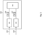
- FIG. 1 shows a system 100 for recording field data in a vehicle.
- the system 100 comprises an RF data acquisition unit 101, a digital data acquisition unit 103 and a data collection unit 105.
- the RF data acquisition unit 101 is configured to obtain RF data 102. This is e.g. done by receiving an RF signal (e.g. by means of an antenna) and obtaining the RF data 102 based on the received RF signal. Optionally, this may also include generating a digital signal from the received RF signal, to obtain the RF data 102.
- the digital data acquisition unit 103 is configured to obtain digital data 104.
- the digital data 104 can, for example, be obtained from sensors, which are connected to the system 100 (which are not part of the system 100, however).
- the data collection unit 105 is configured to receive the RF data 102 from the RF data acquisition unit 101 and is configured to receive the digital data 104 from the digital data acquisition unit 103.
- the RF data 102 comprises a timestamp 106 and the digital data 104 comprises a timestamp 107.
- the timestamp 106 for example, is added to the RF data 102 in the RF data acquisition unit 101.
- the timestamp 107 is added to the digital data 104 in the digital data acquisition unit 103.
- the data collection unit 105 synchronizes the RF data 102 and the digital data 104 based on the timestamp 106 and based on the timestamp 107.
- the RF data 102 processed by the system 100 comprises data representing an in-phase and/or a quadrature component of an RF signal.
- the digital data 104 processed by the system 100 represents sensor data.
- the sensor data may, for example, be obtained from a LIN/CAN bus of a vehicle.
- wireless data and/or a wireless spectrum to which a vehicle (which comprises the system 100) is exposed can be recorded.
- the recorded wireless data and the recorded sensor data can be combined to enable holistic real world scenario test simulations.
- the data, which is recorded by the system 100 can for example be used in simulation software for testing autonomous vehicles in a laboratory environment with real world data.
- a simulation software may for example include scenario visualization with a 3D engine (e.g. unity).
- AI generated test scenarios which are based on the real world data may enable unlimited real world scenario constellations.
- this allows for simulating and testing wireless interference and anomalies.
- the data, which is obtained by the system 100 can for example be provided by means of a cloud-based approach to facilitate scalability of parallel simulations.
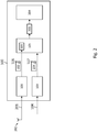
- FIG. 2 shows a schematic view of the system 100 in more detail.
- the system 100 as shown in FIG. 2 comprises all features and function of the system 100 as shown in FIG. 1 .
- same reference signs as in FIG. 1 are used for same features in FIG. 2 .
- the system 100 as shown in FIG. 2 includes the following features, each of which is optional:
- the system 100 is configured to receive a RF signal 201 and to convert the received RF signal 201 into an in-phase quadrature (IQ) signal to obtain the RF data 102.
- IQ in-phase quadrature
- the system 100 may optionally comprise and antenna 202, which is configured to receive the RF signal 201.
- the RF signal 201 which is received by the system 100 optionally represents an electromagnetic environment of the vehicle in which the system 100 is applied. That is, the RF signal 201 represents electromagnetic information to which the vehicle is exposed, however, which is not originated by the vehicle (or by parts of the vehicle) itself.
- the data collection unit 105 is configured to generate a synchronized data set 203 as it is shown in FIG. 2 .
- the generation of the synchronized data set 203 is based on the RF data 102 and the digital data 104 which are synchronized by the data collection unit 105 based on the time stamp 106 and the time stamp 107.
- the system 100 optionally comprises a data processing unit 204, which is configured to receive the synchronized data set 203.
- a data processing unit 204 configured to receive the synchronized data set 203.
- the synchronized data set 203 can also be stored on a storage medium and provided to other entities except the system 100 for further processing.
- the synchronized data set 203 can be received, processed and replayed in the system 100 itself. That is, the system 100 provides a solution which is capable of recording synchronized wireless data and sensor data in a vehicle, and which is capable of replaying said data (which represents the real world scenario) in a laboratory environment (that is the synchronized dataset 203 is replayed).
- the data collection unit 105 optionally comprises a RF to digital conversion unit 205.
- the RF to digital conversion unit 205 is configured to convert the received RF data into a digital signal. Thereby, the RF data 102 can be further processed in a digital manner in the data collection unit 105.
- the system 100 is further configured to obtain at least one of: GPS information, real time clock (RTC) information, or GSM information.
- the RF data acquisition unit 101 can add the timestamp 106 to the received RF data 102, based on at least one of the GPS information, the RTC information, and/or the GSM information.
- the digital data acquisition unit 103 can add the timestamp 107 to the received digital data 104 based on at least one of the GPS information, the RTC information, and/or the GSM information.
- FIG. 3 shows a schematic view of an operating scenario according to the present invention.
- FIG. 3 is, however, just for illustrating the operational principle and therefore does not show all features which are e.g. described in view of FIG. 1 and FIG. 2 .
- sensor data 104 of several sensors is obtained. That is, data from a radar sensor 301, a camera 302, a LiDAR sensor 303 and optionally from several other sensors 304 is obtained.
- the obtained data is fused, that is, the data from the several sensors is combined to one kind of digital data 104.
- FIG. 3 also shows a wireless spectrum which is recorded to obtain the RF data 102.
- the RF data 102 and the digital data 104 are synchronized based on timestamps in the data, which forms the real world data shown in FIG. 3 .
- the real world data (that is the synchronized RF data 102 and digital data 104) can be output as a synchronized data set 203 by the system 100.
- the synchronized data set 203 may then be used for simulation in a laboratory environment.
- the synchronized data set 203 may be enriched with additional AI generated scenarios based on the real world data and e.g. additional interferences, before it is used for simulation.
- FIG. 4 shows a method 400 for recording field data in a vehicle.
- the method comprises the step of obtaining 401, RF data 102, by a RF data acquisition unit 101.
- the method 400 further comprises the step of obtaining 402, digital data 104, by a digital data acquisition unit 103.
- the method 400 further comprises the step of receiving 403, by a data collection 105, RF data 102 from the RF data acquisition unit 101, and receiving 404, by the data collection unit 105, the digital data from the digital data acquisition unit 103.
- the method 400 comprises the step of synchronizing 405, by the data collection unit 105, the RF data 102 and the digital data 104 based on a time stamp 106 in the RF data 102 and a time stamp 107 in the digital data 104.
- the digital data 104 represents sensor data and the RF data 102 comprises data representing an in-phase and/or a quadrature component of an RF signal.
Landscapes
- Physics & Mathematics (AREA)
- General Physics & Mathematics (AREA)
- Traffic Control Systems (AREA)
Abstract
Description
- The present invention relates to a testing system for autonomous vehicles, more specifically to a system for recording field data in a vehicle for later use in "field to lab" tests. In other words, the present invention relates to a data recorder for transportation scenarios, which allows for holistic data logging. The present invention in particular provides a system for obtaining radio frequency (RF) data and sensor data in a synchronized manner.
- Simulations for autonomous vehicles focus on scenarios under various conditions. Worldwide tests are required to test autonomous vehicles in real-world scenarios. Long development and multiple testing cycles are required, wherein regulations and the growing complexity of autonomous vehicles require more and more complex tests. That is, automotive vendors continuously need to optimize evaluation- and development-processes of vehicles and need to meet regulatory laws. This is, for example, done by transitioning pure field tests to "field to lab" tests. During such tests, field data, which is typically obtained during a real life test scenario, is provided in a laboratory environment where a test vehicle can be exposed to the obtained real life field data. This can be done in a physical setup, or in a simulation.
- Conventional solutions for example allow for identifying characteristics (i.e. field data) of a dynamic object in a physical environment of a vehicle, wherein the characteristics can then be used in a simulation of the behavior of the dynamic object and the vehicle in a simulated environment.
- However, due to increased automation of autonomous vehicles, test scenarios are required for which the field data, which is obtained by conventional solutions, is not sufficient. Regulatory rules get more stringent due to the risk of autonomous driving and public safety aspects.
- That is, there is lack of a system, which can obtain field data, which is sufficient for "field to lab" tests for autonomous vehicles.
- Therefore, the object of the invention is to provide a system for recording field data in vehicles, wherein the field data includes RF data and sensor data, which are synchronized based on timestamps in the RF data and the sensor data. Moreover, the object is to provide an according method, computer program product and computer-readable storage medium.
- The object is solved by the features of the first independent claim for the system and by the features of the second independent claim for the method. Further, it is solved by the features of an associated computer program product and by a computer-readable storage medium. The dependent claims contain further developments.
- An inventive system for recording field data in a vehicle comprises a RF data acquisition unit, configured to obtain RF data; a digital data acquisition unit, configured to obtain digital data; a data collection unit, configured to receive the RF data from the RF data acquisition unit and to receive the digital data from the digital data acquisition unit; wherein the data collection unit is configured to synchronize the RF data and the digital data based on a timestamp in the RF data and a timestamp in the digital data; wherein the RF data comprises data representing an in-phase and/or a quadrature component of an RF signal, and the digital data represents sensor data.
- This is beneficial, as a holistic simulation tool for autonomous vehicles can be provided. Optionally, such a tool can e.g. be equipped with visualization, management, and documentation functionality. In particular, this simulation tool can bring RF data and sensor data for real-world scenario simulation to a laboratory environment. In addition to only doing tests and simulations, which are only based on sensor data, wireless interference and anomaly simulations can be performed based on the synchronized RF data and sensor data, to increase the variety of test conditions and scenarios.
- In addition to typical as well as unusual traffic situations, simulations can also cover safety threats like wireless spectrum interferences and anomalies, EMC interferences, jamming (flooding a vehicle with RF noise), spoofing (attacking a vehicle with false RF information).
- In addition to standard test scenarios, unlimited individual tests can be covered with artificial intelligence (AI) based scenario creation. AI for example can inject and/or replace objects in a simulated environment, generate new environments, create wireless interference, or change a weather condition.
- The present invention can also be used for data logging in autonomous vehicles to trace accident data for insurances and improvements.
- The present invention is not only limited to be used in the automotive industry, but can also be applied in other transportation segments such as a train, a ship, urban air mobility, a plane, a drone, a motorbike, a bicycle, or autonomous driving.
- Again in other words, the present invention allows brining real world RF scenarios to a laboratory environment, enabling a user to run the real life scenario in a virtual environment and if required add disturbing or additionally wanted signals to it.
- The holistic data logging solution provided by the present invention is in particular beneficial as it covers all possible aspects by recording sensor data in real time, and brings them to the lab in addition to the RF data. Moreover, RF data and sensor data can be provided to the laboratory in a synchronized manner.
- As vehicles do have a huge amount of sensors (e.g. Radar, Camera, Lidar, Pressure, Temperature, Humidity, Acceleration, Positioning, Air quality, Driver health condition), the present invention can be used for prototype development as well as for regulatory compliance tests in simulation tools.
- In order to provide holistic scenario, recording wireless data and sensor data logging is combined in a single setup. This means that RF data (e.g. comprising I/Q data), all sensor data (radar, camera, lidar, pressure, temperature, humidity, acceleration, gyro, positioning (GPS or GNSS), air quality, driver health condition) as well as a processing data set (which is based on the above RF data and sensor data, e.g. in a synchronized manner) can be recorded in real time.
- In particular, the field data, which is recorded in the vehicle, is external field data to which the vehicle is exposed. In particular, external field data is field data, which originates from a source not being part of the vehicle, and/or from a source outside the vehicle.
- In particular, the vehicle is a car, a motorbike, a bicycle, a truck, a train, a helicopter, a drone, a plane, or a ship.
- In particular, the RF data acquisition unit is configured to add a timestamp to the RF data. In particular, the digital data acquisition unit is configured to add a timestamp to the digital data.
- Advantageously and preferably, the RF data acquisition unit is further configured to convert a received RF signal into an in-phase quadrature, IQ, signal, to obtain the RF data.
- This ensures that the RF data can be analyzed and processed in a more efficient and effective manner.
- In particular, the RF data comprises the IQ signal.
- Advantageously and preferably, the system further comprises an antenna configured to receive the RF signal.
- This ensures that the system can receive RF signals in a reliable manner.
- Advantageously and preferably, the RF signal represents an electromagnetic environment of the vehicle.
- This ensures that the simulation, which is based on the synchronized RF data and sensor data, is correctly supplied with a real world scenario recorded by the system.
- In particular, the RF signal, which represents an electromagnetic environment of the vehicle, is an RF signal, which is of origin external to the vehicle. That is, the RF signal is not produced or generated by the vehicle.
- Advantageously and preferably, the data collection unit is further configured to generate a synchronized dataset based on the synchronized RF data and digital data.
- This ensures that the field data which is recorded by the system can be stored in the synchronized dataset, which can be read out later, e.g. in a "field to lab" test.
- Advantageously and preferably, the system further comprises a data processing unit.
- Advantageously and preferably, the data processing unit is further configured to receive, process and replay the synchronized dataset.
- This ensures that the system effectively can be used in a "field to lab" test.
- In particular, replaying the synchronized dataset includes outputting RF data and digital data based on the synchronized dataset.
- Advantageously and preferably, the sensor data includes at least one of: radar data, image data, lidar data, pressure data, temperature data, air quality data, pulse frequency data, ultrasonic data, position data, time data.
- This allows for various kinds of sensor data to be recorded by the system.
- In particular, lidar data can also be called light detection and ranging data. In particular, lidar is a method for optical distance and velocity measurement and remote measurement of atmospheric parameters based on laser technology.
- Advantageously and preferably, the radar data, the image data, the lidar data, the pressure data, the temperature data, the air quality data, the pulse frequency data, the ultrasonic data, the position data, or the time data comprises raw data and/or pre-processed data.
- This allows for even more various kinds of sensor data to be recorded by the system.
- In particular, pre-processed data includes data obtained by means of image detection and/or sensor fusion. For example, image detection can be performed on the image data, before it is provided to the digital data acquisition unit. For example, the above sensor data may include fused information, which is obtained from at least two different sensors.
- Advantageously and preferably, the data collection unit comprises an RF to digital conversion unit configured to convert the received RF data into a digital signal.
- This allows for optimized processing of the RF signal in the data collection unit.
- In particular, the RF signal is converted to a digital signal when it is received by the data collection unit before other processing of the RF signal in the data collection unit. In particular, the further processing of the RF signal in the data collection unit is based on the converted digital signal of the RF signal.
- Advantageously and preferably, the RF signal and/or the converted digital signal comprises at least one of: UKW data, MW data, GSM data, LTE data, 5G data, GPS data, V2X data.
- This ensures that many kinds of RF signals can be represented in a digital manner for further processing in the system.
- In particular, UKW data may also be called very high frequency, VHF, data. In particular, MW data may also be called medium frequency, MF, data.
- Advantageously and preferably, the system is further configured to obtain at least one of: GPS information, real time clock, RTC, information, or GSM information; and the RF data acquisition unit is configured to add the timestamp to the received RF data based on the GPS information, RTC information and/or GSM information; and/or the digital data acquisition unit is configured to add the timestamp to the received digital data based on the GPS information, RTC information and/or GSM information.
- This ensures that the timestamps can be provided based on reliable time sources.
- An inventive method for recording field data in a vehicle comprises the steps of obtaining, radio frequency, RF, data, by a RF data acquisition unit; obtaining, digital data, by a digital data acquisition unit; receiving, by a data collection unit, the RF data from the RF data acquisition unit; receiving, by the data collection unit, the digital data from the digital data acquisition unit; synchronizing, by the data collection unit, the RF data and the digital data based on a timestamp in the RF data and a timestamp in the digital data; wherein the digital data represents sensor data and the RF data comprises data representing an in-phase and/or a quadrature component of an RF signal.
- Advantageously and preferably, the method further comprises, by the RF data acquisition unit, converting a received RF signal into an in-phase quadrature, IQ, signal, to obtain the RF data.
- Advantageously and preferably, the RF signal represents an electromagnetic environment of the vehicle.
- Advantageously and preferably, the method further comprises generating, by the data collection unit, a synchronized dataset based on the synchronized RF data and digital data.
- Advantageously and preferably, the method further comprises receiving, processing and replaying by a data processing unit, the synchronized dataset.
- Advantageously and preferably, the sensor data includes at least one of: radar data, image data, lidar data, pressure data, temperature data, air quality data, pulse frequency data, ultrasonic data, position data, time data.
- Advantageously and preferably, the radar data, the image data, the lidar data, the pressure data, the temperature data, the air quality data, the pulse frequency data, the ultrasonic data, the position data, or the time data comprises raw data and/or pre-processed data.
- Advantageously and preferably, the data collection unit comprises a RF to digital conversion unit, which converts the received RF data into a digital signal.
- Advantageously and preferably, the RF signal and/or the converted digital signal comprises at least one of: UKW data, MW data, GSM data, LTE data, 5G data, GPS data, V2X data.
- Advantageously and preferably, the method further includes obtaining at least one of: GPS information, real time clock, RTC, information or GSM information; and adding, by the RF data acquisition unit, the timestamp to the received RF data based on the GPS information, RTC information and/or GSM information; and/or adding, by the RF data acquisition unit, the timestamp to the received digital data based on the GPS information, RTC information and/or GSM information.
- The inventive method comprises the same advantages as the inventive system.
- An inventive computer program product comprises instructions, which when the program is executed by a computer, cause the computer to carry out the steps of the above described inventive method or any of its advantageous implementation forms.
- The inventive computer program product comprises the same advantages as the inventive device.
- An inventive computer-readable storage medium comprises instructions which, when executed by a computer, cause the computer to carry out the steps of the above described inventive method or any of its advantageous implementation forms.
- The inventive computer-readable storage medium comprises the same advantages as the inventive device.
- An exemplary embodiment of the invention is now further explained with respect to the drawings by way of examples only, in which
- FIG. 1
- shows a schematic view of a system according to an embodiment of the present invention;
- FIG. 2
- shows a schematic view of a system according to an embodiment of the present invention in more detail;
- FIG. 3
- shows a schematic view of an operating scenario according to the present invention;
- FIG. 4
- shows a schematic view of a method according to an embodiment of the present invention.
- In the following, the structure and function of an embodiment of the inventive system is described based on
-
FIG. 1 in general, and based onFIG. 2 in more detail. InFIG. 3 , an operating scenario according to the present invention is described. In view ofFIG. 4 , the function of an embodiment of the inventive method is described. -
FIG. 1 shows asystem 100 for recording field data in a vehicle. As shown inFIG. 1 , thesystem 100 comprises an RFdata acquisition unit 101, a digitaldata acquisition unit 103 and adata collection unit 105. The RFdata acquisition unit 101 is configured to obtainRF data 102. This is e.g. done by receiving an RF signal (e.g. by means of an antenna) and obtaining theRF data 102 based on the received RF signal. Optionally, this may also include generating a digital signal from the received RF signal, to obtain theRF data 102. The digitaldata acquisition unit 103 is configured to obtaindigital data 104. Thedigital data 104 can, for example, be obtained from sensors, which are connected to the system 100 (which are not part of thesystem 100, however). - The
data collection unit 105 is configured to receive theRF data 102 from the RFdata acquisition unit 101 and is configured to receive thedigital data 104 from the digitaldata acquisition unit 103. As it is shown inFIG. 1 , theRF data 102 comprises atimestamp 106 and thedigital data 104 comprises atimestamp 107. Thetimestamp 106, for example, is added to theRF data 102 in the RFdata acquisition unit 101. Thetimestamp 107, for example, is added to thedigital data 104 in the digitaldata acquisition unit 103. Once thedata collection unit 105 receives theRF data 102 and thedigital data 104, thedata collection unit 105 synchronizes theRF data 102 and thedigital data 104 based on thetimestamp 106 and based on thetimestamp 107. - The
RF data 102 processed by thesystem 100 comprises data representing an in-phase and/or a quadrature component of an RF signal. As already mentioned, thedigital data 104 processed by thesystem 100 represents sensor data. - Thereby, all kinds of available sensor data, which are generated in a vehicle, can be collected by the
system 100. The sensor data may, for example, be obtained from a LIN/CAN bus of a vehicle. In parallel, wireless data and/or a wireless spectrum to which a vehicle (which comprises the system 100) is exposed, can be recorded. In turn, the recorded wireless data and the recorded sensor data can be combined to enable holistic real world scenario test simulations. - The data, which is recorded by the
system 100, can for example be used in simulation software for testing autonomous vehicles in a laboratory environment with real world data. Such a simulation software may for example include scenario visualization with a 3D engine (e.g. unity). Optionally, AI generated test scenarios which are based on the real world data may enable unlimited real world scenario constellations. In addition, this allows for simulating and testing wireless interference and anomalies. The data, which is obtained by thesystem 100, can for example be provided by means of a cloud-based approach to facilitate scalability of parallel simulations. -
FIG. 2 shows a schematic view of thesystem 100 in more detail. Thesystem 100 as shown inFIG. 2 comprises all features and function of thesystem 100 as shown inFIG. 1 . To this end, same reference signs as inFIG. 1 are used for same features inFIG. 2 . Moreover, thesystem 100 as shown inFIG. 2 includes the following features, each of which is optional:
Optionally, thesystem 100 is configured to receive aRF signal 201 and to convert the receivedRF signal 201 into an in-phase quadrature (IQ) signal to obtain theRF data 102. - The
system 100 may optionally comprise andantenna 202, which is configured to receive theRF signal 201. The RF signal 201 which is received by the system 100 (e.g. by means of the antenna 202) optionally represents an electromagnetic environment of the vehicle in which thesystem 100 is applied. That is, theRF signal 201 represents electromagnetic information to which the vehicle is exposed, however, which is not originated by the vehicle (or by parts of the vehicle) itself. - Optionally, the
data collection unit 105 is configured to generate asynchronized data set 203 as it is shown inFIG. 2 . The generation of thesynchronized data set 203 is based on theRF data 102 and thedigital data 104 which are synchronized by thedata collection unit 105 based on thetime stamp 106 and thetime stamp 107. - As illustrated in
FIG. 2 , thesystem 100 optionally comprises adata processing unit 204, which is configured to receive thesynchronized data set 203. Although this is not shown inFIG. 2 , thesynchronized data set 203 can also be stored on a storage medium and provided to other entities except thesystem 100 for further processing. - By means of the
data processing unit 204 thesynchronized data set 203 can be received, processed and replayed in thesystem 100 itself. That is, thesystem 100 provides a solution which is capable of recording synchronized wireless data and sensor data in a vehicle, and which is capable of replaying said data (which represents the real world scenario) in a laboratory environment (that is thesynchronized dataset 203 is replayed). - As it is illustrated in
FIG. 2 , thedata collection unit 105 optionally comprises a RF todigital conversion unit 205. The RF todigital conversion unit 205 is configured to convert the received RF data into a digital signal. Thereby, theRF data 102 can be further processed in a digital manner in thedata collection unit 105. - Optionally, the
system 100 is further configured to obtain at least one of: GPS information, real time clock (RTC) information, or GSM information. Based on this information, the RFdata acquisition unit 101 can add thetimestamp 106 to the receivedRF data 102, based on at least one of the GPS information, the RTC information, and/or the GSM information. Further optionally, the digitaldata acquisition unit 103 can add thetimestamp 107 to the receiveddigital data 104 based on at least one of the GPS information, the RTC information, and/or the GSM information. -
FIG. 3 shows a schematic view of an operating scenario according to the present invention.FIG. 3 is, however, just for illustrating the operational principle and therefore does not show all features which are e.g. described in view ofFIG. 1 andFIG. 2 . - As shown in
FIG. 3 ,sensor data 104 of several sensors is obtained. That is, data from aradar sensor 301, a camera 302, aLiDAR sensor 303 and optionally from severalother sensors 304 is obtained. The obtained data is fused, that is, the data from the several sensors is combined to one kind ofdigital data 104.FIG. 3 also shows a wireless spectrum which is recorded to obtain theRF data 102. TheRF data 102 and thedigital data 104 are synchronized based on timestamps in the data, which forms the real world data shown inFIG. 3 . The real world data (that is thesynchronized RF data 102 and digital data 104) can be output as asynchronized data set 203 by thesystem 100. Thesynchronized data set 203 may then be used for simulation in a laboratory environment. Thesynchronized data set 203 may be enriched with additional AI generated scenarios based on the real world data and e.g. additional interferences, before it is used for simulation. -
FIG. 4 shows amethod 400 for recording field data in a vehicle. As illustrated inFIG. 4 , the method comprises the step of obtaining 401,RF data 102, by a RFdata acquisition unit 101. Themethod 400 further comprises the step of obtaining 402,digital data 104, by a digitaldata acquisition unit 103. Themethod 400 further comprises the step of receiving 403, by adata collection 105,RF data 102 from the RFdata acquisition unit 101, and receiving 404, by thedata collection unit 105, the digital data from the digitaldata acquisition unit 103. Further, themethod 400 comprises the step of synchronizing 405, by thedata collection unit 105, theRF data 102 and thedigital data 104 based on atime stamp 106 in theRF data 102 and atime stamp 107 in thedigital data 104. Thedigital data 104 represents sensor data and theRF data 102 comprises data representing an in-phase and/or a quadrature component of an RF signal. - It is important to note that the inventive system and method very closely correspond. Therefore, all of the above said regarding the system is also applicable to the method and vice versa. Everything, which is described in the description and/or claimed in the claims and/or drawn in the drawings, can be combined.
- The invention is not limited to the illustrated embodiment. All features described above or features shown in the figures can be combined with each other in any advantageous manner within the scope of the invention.
Claims (15)
- A system (100) for recording field data in a vehicle, wherein the system (100) comprises:- a radio frequency, RF, data acquisition unit (101), configured to obtain RF data (102);- a digital data acquisition unit (103), configured to obtain digital data (104);- a data collection unit (105), configured to receive the RF data (102) from the RF data acquisition unit (101) and to receive the digital data (104) from the digital data acquisition unit (103);wherein the data collection unit (105) is configured to synchronize the RF data (102) and the digital data (104) based on a timestamp (106) in the RF data (102) and a timestamp (107) in the digital data (104);
wherein the RF data (102) comprises data representing an in-phase and/or a quadrature component of an RF signal, and the digital data (104) represents sensor data. - The system (100) according to claim 1, wherein the RF data acquisition unit (101) is further configured to convert a received RF signal (201) into an in-phase quadrature, IQ, signal, to obtain the RF data (102).
- The system (100) according to claim 1 or 2, wherein the system (100) further comprises an antenna (202) configured to receive the RF signal (201).
- The system (100) according to any one of the preceding claims, wherein the RF signal (201) represents an electromagnetic environment of the vehicle.
- The system (100) according to any one of the preceding claims, wherein the data collection unit (105) is further configured to generate a synchronized dataset (203) based on the synchronized RF data (102) and digital data (104).
- The system (100) according to any one of the preceding claims, wherein the system (100) further comprises a data processing unit (204).
- The system (100) according to any one of the preceding claims, wherein the data processing unit (204) is further configured to receive, process and replay the synchronized dataset (203).
- The system (100) according to any one of the preceding claims, wherein the sensor data (104) includes at least one of: radar data, image data, lidar data, pressure data, temperature data, air quality data, pulse frequency data, ultrasonic data, position data, time data.
- The system (100) according to any one of the preceding claims, wherein the radar data, the image data, the lidar data, the pressure data, the temperature data, the air quality data, the pulse frequency data, the ultrasonic data, the position data, or the time data comprises raw data and/or pre-processed data.
- The system (100) according to any one of the preceding claims, wherein the data collection unit (105) comprises an RF to digital conversion unit (205) configured to convert the received RF data (102) into a digital signal.
- The system (100) according to any one of the preceding claims, wherein the RF signal and/or the converted digital signal comprises at least one of: UKW data, MW data, GSM data, LTE data, 5G data, GPS data, V2X data.
- The system (100) according to any one of the preceding claims, further configured to obtain at least one of: GPS information, real time clock, RTC, information, or GSM information; and
wherein the RF data acquisition unit (101) is configured to add the timestamp (106) to the received RF data (102) based on the GPS information, RTC information and/or GSM information; and/or
wherein the digital data acquisition unit (103) is configured to add the timestamp (107) to the received digital data (104) based on the GPS information, RTC information and/or GSM information. - A method (400) for recording field data in a vehicle, wherein the method (400) comprises the steps of:- obtaining (401), radio frequency, RF, data (102), by a RF data acquisition unit (101);- obtaining (402), digital data (104), by a digital data acquisition unit (103);- receiving (403), by a data collection unit (105), the RF data (102) from the RF data acquisition unit (101);- receiving (404), by the data collection unit (105), the digital data (104) from the digital data acquisition unit (103) ;- synchronizing (405), by the data collection unit (105), the RF data (102) and the digital data (104) based on a timestamp (106) in the RF data (102) and a timestamp (107) in the digital data (104);wherein the digital data (104) represents sensor data and the RF data (102) comprises data representing an in-phase and/or a quadrature component of an RF signal.
- A computer program product comprising instructions which, when the program is executed by a computer, cause the computer to carry out the steps of the method (400) of claim 13.
- A computer-readable storage medium comprising instructions which, when executed by a computer, cause the computer to carry out the steps of the method (400) of claim 13.
Priority Applications (1)
| Application Number | Priority Date | Filing Date | Title |
|---|---|---|---|
| EP19209071.0A EP3822924B1 (en) | 2019-11-14 | 2019-11-14 | System and method for recording field data in a vehicle |
Applications Claiming Priority (1)
| Application Number | Priority Date | Filing Date | Title |
|---|---|---|---|
| EP19209071.0A EP3822924B1 (en) | 2019-11-14 | 2019-11-14 | System and method for recording field data in a vehicle |
Publications (2)
| Publication Number | Publication Date |
|---|---|
| EP3822924A1 true EP3822924A1 (en) | 2021-05-19 |
| EP3822924B1 EP3822924B1 (en) | 2024-04-03 |
Family
ID=68581530
Family Applications (1)
| Application Number | Title | Priority Date | Filing Date |
|---|---|---|---|
| EP19209071.0A Active EP3822924B1 (en) | 2019-11-14 | 2019-11-14 | System and method for recording field data in a vehicle |
Country Status (1)
| Country | Link |
|---|---|
| EP (1) | EP3822924B1 (en) |
Cited By (1)
| Publication number | Priority date | Publication date | Assignee | Title |
|---|---|---|---|---|
| DE102023131698A1 (en) | 2023-11-14 | 2025-05-15 | Cariad Se | Method and device for analyzing radiation characteristics of a motor vehicle |
Citations (5)
| Publication number | Priority date | Publication date | Assignee | Title |
|---|---|---|---|---|
| US20030210181A1 (en) * | 2002-05-13 | 2003-11-13 | James R. Hager | Methods and apparatus for radar data processing |
| US20080036617A1 (en) * | 2005-09-09 | 2008-02-14 | Arms Steven W | Energy harvesting, wireless structural health monitoring system |
| EP3090354A1 (en) * | 2013-12-30 | 2016-11-09 | Google Technology Holdings LLC | Methods and systems for synchronizing data received from multiple sensors of a device |
| US20180088584A1 (en) * | 2015-12-11 | 2018-03-29 | Uber Technologies, Inc. | Formatting sensor data for use in autonomous vehicle communications platform |
| US20190156600A1 (en) * | 2006-11-16 | 2019-05-23 | Ge Global Sourcing Llc | Locomotive sensor system for monitoring engine and lubricant health |
-
2019
- 2019-11-14 EP EP19209071.0A patent/EP3822924B1/en active Active
Patent Citations (5)
| Publication number | Priority date | Publication date | Assignee | Title |
|---|---|---|---|---|
| US20030210181A1 (en) * | 2002-05-13 | 2003-11-13 | James R. Hager | Methods and apparatus for radar data processing |
| US20080036617A1 (en) * | 2005-09-09 | 2008-02-14 | Arms Steven W | Energy harvesting, wireless structural health monitoring system |
| US20190156600A1 (en) * | 2006-11-16 | 2019-05-23 | Ge Global Sourcing Llc | Locomotive sensor system for monitoring engine and lubricant health |
| EP3090354A1 (en) * | 2013-12-30 | 2016-11-09 | Google Technology Holdings LLC | Methods and systems for synchronizing data received from multiple sensors of a device |
| US20180088584A1 (en) * | 2015-12-11 | 2018-03-29 | Uber Technologies, Inc. | Formatting sensor data for use in autonomous vehicle communications platform |
Cited By (1)
| Publication number | Priority date | Publication date | Assignee | Title |
|---|---|---|---|---|
| DE102023131698A1 (en) | 2023-11-14 | 2025-05-15 | Cariad Se | Method and device for analyzing radiation characteristics of a motor vehicle |
Also Published As
| Publication number | Publication date |
|---|---|
| EP3822924B1 (en) | 2024-04-03 |
Similar Documents
| Publication | Publication Date | Title |
|---|---|---|
| CN109218075B (en) | A hardware-in-the-loop-based V2X scenario testing method and system | |
| CN109993849A (en) | A kind of automatic driving test scene reproduction simulation method, device and system | |
| CN110780608B (en) | Simulation test method and device | |
| US11255962B2 (en) | Automotive testing method, system and computer program product | |
| US11656328B2 (en) | Validating object detection hardware and algorithms | |
| CN103278822B (en) | Based on satellite navigation and location system performance evaluation system and the method for HLA platform | |
| CN114970085A (en) | High-precision map simulation test method and system | |
| CN115391422B (en) | Vehicle perception information generation method, device, equipment, medium and program product | |
| US20230306729A1 (en) | Device and method for decision support of an artificial cognitive system | |
| CN111541990A (en) | System, method and device for acquiring test data of vehicle-road cooperative system | |
| CN116449807B (en) | Simulation test method and system for automobile control system of Internet of things | |
| CN115014392A (en) | GNSS combined navigation positioning precision test method and system under satellite loss of lock | |
| Razdan | Unsettled technology areas in autonomous vehicle test and validation | |
| CN116007658B (en) | Combined calibration method, device and controller of laser radar and integrated navigation system | |
| CN116955179A (en) | Intelligent networking scene automatic test system, method and equipment | |
| EP3822924B1 (en) | System and method for recording field data in a vehicle | |
| CN111401423B (en) | Data processing method and device for automatic driving vehicle | |
| Wang et al. | A hardware-in-the-loop V2X simulation framework: CarTest | |
| CN120524293A (en) | UAV fault prediction method and system based on deep learning | |
| CN116010289A (en) | Automatic driving simulation scene test method, device, electronic equipment and readable medium | |
| CN114884525A (en) | Positioning method for ADS-B (automatic dependent surveillance broadcast) aviation system | |
| RU2755776C1 (en) | METHOD FOR TESTING THE BEHAVIOUR OF UAVs UNDER CONDITIONS OF DISTORTION OR SUPPRESSION OF THE NAVIGATION FIELD OF A SATELLITE NAVIGATION SYSTEM | |
| Reichel et al. | A forensic analysis of GNSS spoofing attacks on autonomous vehicles | |
| CN113671936A (en) | Driving assistance system test method and system, electronic device and storage medium | |
| Gasco et al. | TRACEN-X: Telemetry Replay and Analysis of CAN Bus and External Navigation Data |
Legal Events
| Date | Code | Title | Description |
|---|---|---|---|
| PUAI | Public reference made under article 153(3) epc to a published international application that has entered the european phase |
Free format text: ORIGINAL CODE: 0009012 |
|
| STAA | Information on the status of an ep patent application or granted ep patent |
Free format text: STATUS: THE APPLICATION HAS BEEN PUBLISHED |
|
| AK | Designated contracting states |
Kind code of ref document: A1 Designated state(s): AL AT BE BG CH CY CZ DE DK EE ES FI FR GB GR HR HU IE IS IT LI LT LU LV MC MK MT NL NO PL PT RO RS SE SI SK SM TR |
|
| STAA | Information on the status of an ep patent application or granted ep patent |
Free format text: STATUS: REQUEST FOR EXAMINATION WAS MADE |
|
| 17P | Request for examination filed |
Effective date: 20210812 |
|
| RBV | Designated contracting states (corrected) |
Designated state(s): AL AT BE BG CH CY CZ DE DK EE ES FI FR GB GR HR HU IE IS IT LI LT LU LV MC MK MT NL NO PL PT RO RS SE SI SK SM TR |
|
| GRAP | Despatch of communication of intention to grant a patent |
Free format text: ORIGINAL CODE: EPIDOSNIGR1 |
|
| STAA | Information on the status of an ep patent application or granted ep patent |
Free format text: STATUS: GRANT OF PATENT IS INTENDED |
|
| INTG | Intention to grant announced |
Effective date: 20240115 |
|
| GRAS | Grant fee paid |
Free format text: ORIGINAL CODE: EPIDOSNIGR3 |
|
| GRAA | (expected) grant |
Free format text: ORIGINAL CODE: 0009210 |
|
| STAA | Information on the status of an ep patent application or granted ep patent |
Free format text: STATUS: THE PATENT HAS BEEN GRANTED |
|
| AK | Designated contracting states |
Kind code of ref document: B1 Designated state(s): AL AT BE BG CY CZ DE DK EE ES FI FR GB GR HR HU IS IT LT LU LV MC MK MT NL NO PL PT RO RS SE SI SK SM TR |
|
| RBV | Designated contracting states (corrected) |
Designated state(s): AL AT BE BG CY CZ DE DK EE ES FI FR GB GR HR HU IS IT LT LU LV MC MK MT NL NO PL PT RO RS SE SI SK SM TR |
|
| REG | Reference to a national code |
Ref country code: DE Ref legal event code: R096 Ref document number: 602019049359 Country of ref document: DE |
|
| REG | Reference to a national code |
Ref country code: LT Ref legal event code: MG9D |
|
| REG | Reference to a national code |
Ref country code: NL Ref legal event code: MP Effective date: 20240403 |
|
| REG | Reference to a national code |
Ref country code: AT Ref legal event code: MK05 Ref document number: 1673229 Country of ref document: AT Kind code of ref document: T Effective date: 20240403 |
|
| PG25 | Lapsed in a contracting state [announced via postgrant information from national office to epo] |
Ref country code: NL Free format text: LAPSE BECAUSE OF FAILURE TO SUBMIT A TRANSLATION OF THE DESCRIPTION OR TO PAY THE FEE WITHIN THE PRESCRIBED TIME-LIMIT Effective date: 20240403 |
|
| PG25 | Lapsed in a contracting state [announced via postgrant information from national office to epo] |
Ref country code: NL Free format text: LAPSE BECAUSE OF FAILURE TO SUBMIT A TRANSLATION OF THE DESCRIPTION OR TO PAY THE FEE WITHIN THE PRESCRIBED TIME-LIMIT Effective date: 20240403 |
|
| PG25 | Lapsed in a contracting state [announced via postgrant information from national office to epo] |
Ref country code: IS Free format text: LAPSE BECAUSE OF FAILURE TO SUBMIT A TRANSLATION OF THE DESCRIPTION OR TO PAY THE FEE WITHIN THE PRESCRIBED TIME-LIMIT Effective date: 20240803 |
|
| PG25 | Lapsed in a contracting state [announced via postgrant information from national office to epo] |
Ref country code: BG Free format text: LAPSE BECAUSE OF FAILURE TO SUBMIT A TRANSLATION OF THE DESCRIPTION OR TO PAY THE FEE WITHIN THE PRESCRIBED TIME-LIMIT Effective date: 20240403 |
|
| PG25 | Lapsed in a contracting state [announced via postgrant information from national office to epo] |
Ref country code: HR Free format text: LAPSE BECAUSE OF FAILURE TO SUBMIT A TRANSLATION OF THE DESCRIPTION OR TO PAY THE FEE WITHIN THE PRESCRIBED TIME-LIMIT Effective date: 20240403 Ref country code: FI Free format text: LAPSE BECAUSE OF FAILURE TO SUBMIT A TRANSLATION OF THE DESCRIPTION OR TO PAY THE FEE WITHIN THE PRESCRIBED TIME-LIMIT Effective date: 20240403 |
|
| PG25 | Lapsed in a contracting state [announced via postgrant information from national office to epo] |
Ref country code: GR Free format text: LAPSE BECAUSE OF FAILURE TO SUBMIT A TRANSLATION OF THE DESCRIPTION OR TO PAY THE FEE WITHIN THE PRESCRIBED TIME-LIMIT Effective date: 20240704 |
|
| PG25 | Lapsed in a contracting state [announced via postgrant information from national office to epo] |
Ref country code: PT Free format text: LAPSE BECAUSE OF FAILURE TO SUBMIT A TRANSLATION OF THE DESCRIPTION OR TO PAY THE FEE WITHIN THE PRESCRIBED TIME-LIMIT Effective date: 20240805 |
|
| PG25 | Lapsed in a contracting state [announced via postgrant information from national office to epo] |
Ref country code: ES Free format text: LAPSE BECAUSE OF FAILURE TO SUBMIT A TRANSLATION OF THE DESCRIPTION OR TO PAY THE FEE WITHIN THE PRESCRIBED TIME-LIMIT Effective date: 20240403 |
|
| PG25 | Lapsed in a contracting state [announced via postgrant information from national office to epo] |
Ref country code: CZ Free format text: LAPSE BECAUSE OF FAILURE TO SUBMIT A TRANSLATION OF THE DESCRIPTION OR TO PAY THE FEE WITHIN THE PRESCRIBED TIME-LIMIT Effective date: 20240403 |
|
| PG25 | Lapsed in a contracting state [announced via postgrant information from national office to epo] |
Ref country code: AT Free format text: LAPSE BECAUSE OF FAILURE TO SUBMIT A TRANSLATION OF THE DESCRIPTION OR TO PAY THE FEE WITHIN THE PRESCRIBED TIME-LIMIT Effective date: 20240403 |
|
| PG25 | Lapsed in a contracting state [announced via postgrant information from national office to epo] |
Ref country code: PL Free format text: LAPSE BECAUSE OF FAILURE TO SUBMIT A TRANSLATION OF THE DESCRIPTION OR TO PAY THE FEE WITHIN THE PRESCRIBED TIME-LIMIT Effective date: 20240403 |
|
| PG25 | Lapsed in a contracting state [announced via postgrant information from national office to epo] |
Ref country code: LV Free format text: LAPSE BECAUSE OF FAILURE TO SUBMIT A TRANSLATION OF THE DESCRIPTION OR TO PAY THE FEE WITHIN THE PRESCRIBED TIME-LIMIT Effective date: 20240403 |
|
| PG25 | Lapsed in a contracting state [announced via postgrant information from national office to epo] |
Ref country code: PT Free format text: LAPSE BECAUSE OF FAILURE TO SUBMIT A TRANSLATION OF THE DESCRIPTION OR TO PAY THE FEE WITHIN THE PRESCRIBED TIME-LIMIT Effective date: 20240805 Ref country code: PL Free format text: LAPSE BECAUSE OF FAILURE TO SUBMIT A TRANSLATION OF THE DESCRIPTION OR TO PAY THE FEE WITHIN THE PRESCRIBED TIME-LIMIT Effective date: 20240403 Ref country code: NO Free format text: LAPSE BECAUSE OF FAILURE TO SUBMIT A TRANSLATION OF THE DESCRIPTION OR TO PAY THE FEE WITHIN THE PRESCRIBED TIME-LIMIT Effective date: 20240703 Ref country code: LV Free format text: LAPSE BECAUSE OF FAILURE TO SUBMIT A TRANSLATION OF THE DESCRIPTION OR TO PAY THE FEE WITHIN THE PRESCRIBED TIME-LIMIT Effective date: 20240403 Ref country code: IS Free format text: LAPSE BECAUSE OF FAILURE TO SUBMIT A TRANSLATION OF THE DESCRIPTION OR TO PAY THE FEE WITHIN THE PRESCRIBED TIME-LIMIT Effective date: 20240803 Ref country code: HR Free format text: LAPSE BECAUSE OF FAILURE TO SUBMIT A TRANSLATION OF THE DESCRIPTION OR TO PAY THE FEE WITHIN THE PRESCRIBED TIME-LIMIT Effective date: 20240403 Ref country code: GR Free format text: LAPSE BECAUSE OF FAILURE TO SUBMIT A TRANSLATION OF THE DESCRIPTION OR TO PAY THE FEE WITHIN THE PRESCRIBED TIME-LIMIT Effective date: 20240704 Ref country code: FI Free format text: LAPSE BECAUSE OF FAILURE TO SUBMIT A TRANSLATION OF THE DESCRIPTION OR TO PAY THE FEE WITHIN THE PRESCRIBED TIME-LIMIT Effective date: 20240403 Ref country code: ES Free format text: LAPSE BECAUSE OF FAILURE TO SUBMIT A TRANSLATION OF THE DESCRIPTION OR TO PAY THE FEE WITHIN THE PRESCRIBED TIME-LIMIT Effective date: 20240403 Ref country code: CZ Free format text: LAPSE BECAUSE OF FAILURE TO SUBMIT A TRANSLATION OF THE DESCRIPTION OR TO PAY THE FEE WITHIN THE PRESCRIBED TIME-LIMIT Effective date: 20240403 Ref country code: BG Free format text: LAPSE BECAUSE OF FAILURE TO SUBMIT A TRANSLATION OF THE DESCRIPTION OR TO PAY THE FEE WITHIN THE PRESCRIBED TIME-LIMIT Effective date: 20240403 Ref country code: AT Free format text: LAPSE BECAUSE OF FAILURE TO SUBMIT A TRANSLATION OF THE DESCRIPTION OR TO PAY THE FEE WITHIN THE PRESCRIBED TIME-LIMIT Effective date: 20240403 Ref country code: RS Free format text: LAPSE BECAUSE OF FAILURE TO SUBMIT A TRANSLATION OF THE DESCRIPTION OR TO PAY THE FEE WITHIN THE PRESCRIBED TIME-LIMIT Effective date: 20240703 |
|
| REG | Reference to a national code |
Ref country code: DE Ref legal event code: R097 Ref document number: 602019049359 Country of ref document: DE |
|
| PG25 | Lapsed in a contracting state [announced via postgrant information from national office to epo] |
Ref country code: DK Free format text: LAPSE BECAUSE OF FAILURE TO SUBMIT A TRANSLATION OF THE DESCRIPTION OR TO PAY THE FEE WITHIN THE PRESCRIBED TIME-LIMIT Effective date: 20240403 |
|
| PG25 | Lapsed in a contracting state [announced via postgrant information from national office to epo] |
Ref country code: EE Free format text: LAPSE BECAUSE OF FAILURE TO SUBMIT A TRANSLATION OF THE DESCRIPTION OR TO PAY THE FEE WITHIN THE PRESCRIBED TIME-LIMIT Effective date: 20240403 |
|
| PG25 | Lapsed in a contracting state [announced via postgrant information from national office to epo] |
Ref country code: SK Free format text: LAPSE BECAUSE OF FAILURE TO SUBMIT A TRANSLATION OF THE DESCRIPTION OR TO PAY THE FEE WITHIN THE PRESCRIBED TIME-LIMIT Effective date: 20240403 Ref country code: RO Free format text: LAPSE BECAUSE OF FAILURE TO SUBMIT A TRANSLATION OF THE DESCRIPTION OR TO PAY THE FEE WITHIN THE PRESCRIBED TIME-LIMIT Effective date: 20240403 |
|
| PG25 | Lapsed in a contracting state [announced via postgrant information from national office to epo] |
Ref country code: SM Free format text: LAPSE BECAUSE OF FAILURE TO SUBMIT A TRANSLATION OF THE DESCRIPTION OR TO PAY THE FEE WITHIN THE PRESCRIBED TIME-LIMIT Effective date: 20240403 |
|
| PG25 | Lapsed in a contracting state [announced via postgrant information from national office to epo] |
Ref country code: SM Free format text: LAPSE BECAUSE OF FAILURE TO SUBMIT A TRANSLATION OF THE DESCRIPTION OR TO PAY THE FEE WITHIN THE PRESCRIBED TIME-LIMIT Effective date: 20240403 Ref country code: SK Free format text: LAPSE BECAUSE OF FAILURE TO SUBMIT A TRANSLATION OF THE DESCRIPTION OR TO PAY THE FEE WITHIN THE PRESCRIBED TIME-LIMIT Effective date: 20240403 Ref country code: RO Free format text: LAPSE BECAUSE OF FAILURE TO SUBMIT A TRANSLATION OF THE DESCRIPTION OR TO PAY THE FEE WITHIN THE PRESCRIBED TIME-LIMIT Effective date: 20240403 Ref country code: EE Free format text: LAPSE BECAUSE OF FAILURE TO SUBMIT A TRANSLATION OF THE DESCRIPTION OR TO PAY THE FEE WITHIN THE PRESCRIBED TIME-LIMIT Effective date: 20240403 Ref country code: DK Free format text: LAPSE BECAUSE OF FAILURE TO SUBMIT A TRANSLATION OF THE DESCRIPTION OR TO PAY THE FEE WITHIN THE PRESCRIBED TIME-LIMIT Effective date: 20240403 |
|
| PLBE | No opposition filed within time limit |
Free format text: ORIGINAL CODE: 0009261 |
|
| STAA | Information on the status of an ep patent application or granted ep patent |
Free format text: STATUS: NO OPPOSITION FILED WITHIN TIME LIMIT |
|
| 26N | No opposition filed |
Effective date: 20250106 |
|
| P01 | Opt-out of the competence of the unified patent court (upc) registered |
Free format text: CASE NUMBER: APP_7338/2025 Effective date: 20250212 |
|
| PG25 | Lapsed in a contracting state [announced via postgrant information from national office to epo] |
Ref country code: SI Free format text: LAPSE BECAUSE OF FAILURE TO SUBMIT A TRANSLATION OF THE DESCRIPTION OR TO PAY THE FEE WITHIN THE PRESCRIBED TIME-LIMIT Effective date: 20240403 |
|
| PG25 | Lapsed in a contracting state [announced via postgrant information from national office to epo] |
Ref country code: MC Free format text: LAPSE BECAUSE OF FAILURE TO SUBMIT A TRANSLATION OF THE DESCRIPTION OR TO PAY THE FEE WITHIN THE PRESCRIBED TIME-LIMIT Effective date: 20240403 |
|
| PG25 | Lapsed in a contracting state [announced via postgrant information from national office to epo] |
Ref country code: LU Free format text: LAPSE BECAUSE OF NON-PAYMENT OF DUE FEES Effective date: 20241114 |
|
| REG | Reference to a national code |
Ref country code: BE Ref legal event code: MM Effective date: 20241130 |
|
| PG25 | Lapsed in a contracting state [announced via postgrant information from national office to epo] |
Ref country code: SE Free format text: LAPSE BECAUSE OF FAILURE TO SUBMIT A TRANSLATION OF THE DESCRIPTION OR TO PAY THE FEE WITHIN THE PRESCRIBED TIME-LIMIT Effective date: 20240403 |
|
| PG25 | Lapsed in a contracting state [announced via postgrant information from national office to epo] |
Ref country code: BE Free format text: LAPSE BECAUSE OF NON-PAYMENT OF DUE FEES Effective date: 20241130 |
|
| PGFP | Annual fee paid to national office [announced via postgrant information from national office to epo] |
Ref country code: DE Payment date: 20251118 Year of fee payment: 7 |
|
| PGFP | Annual fee paid to national office [announced via postgrant information from national office to epo] |
Ref country code: GB Payment date: 20251120 Year of fee payment: 7 |
|
| PGFP | Annual fee paid to national office [announced via postgrant information from national office to epo] |
Ref country code: FR Payment date: 20251125 Year of fee payment: 7 |
|
| PG25 | Lapsed in a contracting state [announced via postgrant information from national office to epo] |
Ref country code: IT Free format text: LAPSE BECAUSE OF FAILURE TO SUBMIT A TRANSLATION OF THE DESCRIPTION OR TO PAY THE FEE WITHIN THE PRESCRIBED TIME-LIMIT Effective date: 20240403 |
|
| PG25 | Lapsed in a contracting state [announced via postgrant information from national office to epo] |
Ref country code: HU Free format text: LAPSE BECAUSE OF FAILURE TO SUBMIT A TRANSLATION OF THE DESCRIPTION OR TO PAY THE FEE WITHIN THE PRESCRIBED TIME-LIMIT; INVALID AB INITIO Effective date: 20191114 |
|
| PG25 | Lapsed in a contracting state [announced via postgrant information from national office to epo] |
Ref country code: CY Free format text: LAPSE BECAUSE OF FAILURE TO SUBMIT A TRANSLATION OF THE DESCRIPTION OR TO PAY THE FEE WITHIN THE PRESCRIBED TIME-LIMIT; INVALID AB INITIO Effective date: 20191114 |
|
| PG25 | Lapsed in a contracting state [announced via postgrant information from national office to epo] |
Ref country code: TR Free format text: LAPSE BECAUSE OF FAILURE TO SUBMIT A TRANSLATION OF THE DESCRIPTION OR TO PAY THE FEE WITHIN THE PRESCRIBED TIME-LIMIT Effective date: 20240403 |
|
| PG25 | Lapsed in a contracting state [announced via postgrant information from national office to epo] |
Ref country code: LT Free format text: LAPSE BECAUSE OF FAILURE TO SUBMIT A TRANSLATION OF THE DESCRIPTION OR TO PAY THE FEE WITHIN THE PRESCRIBED TIME-LIMIT Effective date: 20240403 |