EP3822669A1 - Transfer sheet, color forming sheet, color forming article, and transfer method - Google Patents
Transfer sheet, color forming sheet, color forming article, and transfer method Download PDFInfo
- Publication number
- EP3822669A1 EP3822669A1 EP19833184.5A EP19833184A EP3822669A1 EP 3822669 A1 EP3822669 A1 EP 3822669A1 EP 19833184 A EP19833184 A EP 19833184A EP 3822669 A1 EP3822669 A1 EP 3822669A1
- Authority
- EP
- European Patent Office
- Prior art keywords
- layer
- film layer
- thin film
- light
- projection
- Prior art date
- Legal status (The legal status is an assumption and is not a legal conclusion. Google has not performed a legal analysis and makes no representation as to the accuracy of the status listed.)
- Pending
Links
- 238000000034 method Methods 0.000 title claims description 38
- 239000010410 layer Substances 0.000 claims abstract description 485
- 239000010409 thin film Substances 0.000 claims abstract description 73
- 239000000758 substrate Substances 0.000 claims abstract description 62
- 239000012790 adhesive layer Substances 0.000 claims abstract description 44
- 230000005540 biological transmission Effects 0.000 claims abstract description 26
- 238000002834 transmittance Methods 0.000 claims abstract description 10
- 239000002356 single layer Substances 0.000 claims description 68
- 239000000463 material Substances 0.000 claims description 18
- 230000008033 biological extinction Effects 0.000 claims description 12
- 238000010438 heat treatment Methods 0.000 claims description 5
- 238000003475 lamination Methods 0.000 claims description 5
- 229920005992 thermoplastic resin Polymers 0.000 claims description 5
- 229910052809 inorganic oxide Inorganic materials 0.000 claims description 4
- 230000031700 light absorption Effects 0.000 claims description 4
- 150000004767 nitrides Chemical class 0.000 claims description 4
- 229910052751 metal Inorganic materials 0.000 claims description 2
- 239000002184 metal Substances 0.000 claims description 2
- 229920005989 resin Polymers 0.000 abstract description 102
- 239000011347 resin Substances 0.000 abstract description 102
- 239000010408 film Substances 0.000 description 136
- 230000000694 effects Effects 0.000 description 41
- 238000010521 absorption reaction Methods 0.000 description 32
- 238000000576 coating method Methods 0.000 description 15
- 238000000149 argon plasma sintering Methods 0.000 description 8
- 230000001965 increasing effect Effects 0.000 description 8
- VYPSYNLAJGMNEJ-UHFFFAOYSA-N silicon dioxide Inorganic materials O=[Si]=O VYPSYNLAJGMNEJ-UHFFFAOYSA-N 0.000 description 8
- 230000008859 change Effects 0.000 description 6
- 239000011248 coating agent Substances 0.000 description 6
- 239000003086 colorant Substances 0.000 description 6
- 239000007788 liquid Substances 0.000 description 6
- 230000003287 optical effect Effects 0.000 description 6
- 241000907681 Morpho Species 0.000 description 5
- 238000009792 diffusion process Methods 0.000 description 5
- 239000002932 luster Substances 0.000 description 5
- 244000241796 Christia obcordata Species 0.000 description 4
- GWEVSGVZZGPLCZ-UHFFFAOYSA-N Titan oxide Chemical compound O=[Ti]=O GWEVSGVZZGPLCZ-UHFFFAOYSA-N 0.000 description 4
- 230000001788 irregular Effects 0.000 description 4
- 238000004519 manufacturing process Methods 0.000 description 4
- BQJCRHHNABKAKU-KBQPJGBKSA-N morphine Chemical compound O([C@H]1[C@H](C=C[C@H]23)O)C4=C5[C@@]12CCN(C)[C@@H]3CC5=CC=C4O BQJCRHHNABKAKU-KBQPJGBKSA-N 0.000 description 4
- 230000009467 reduction Effects 0.000 description 4
- 239000002904 solvent Substances 0.000 description 4
- ZWEHNKRNPOVVGH-UHFFFAOYSA-N 2-Butanone Chemical compound CCC(C)=O ZWEHNKRNPOVVGH-UHFFFAOYSA-N 0.000 description 3
- CSCPPACGZOOCGX-UHFFFAOYSA-N Acetone Chemical compound CC(C)=O CSCPPACGZOOCGX-UHFFFAOYSA-N 0.000 description 3
- XEKOWRVHYACXOJ-UHFFFAOYSA-N Ethyl acetate Chemical compound CCOC(C)=O XEKOWRVHYACXOJ-UHFFFAOYSA-N 0.000 description 3
- YXFVVABEGXRONW-UHFFFAOYSA-N Toluene Chemical compound CC1=CC=CC=C1 YXFVVABEGXRONW-UHFFFAOYSA-N 0.000 description 3
- 238000007611 bar coating method Methods 0.000 description 3
- 230000015572 biosynthetic process Effects 0.000 description 3
- 239000003795 chemical substances by application Substances 0.000 description 3
- 238000007756 gravure coating Methods 0.000 description 3
- 239000000049 pigment Substances 0.000 description 3
- -1 polyethylene terephthalate Polymers 0.000 description 3
- 235000012239 silicon dioxide Nutrition 0.000 description 3
- 239000000377 silicon dioxide Substances 0.000 description 3
- 239000007921 spray Substances 0.000 description 3
- RTAQQCXQSZGOHL-UHFFFAOYSA-N Titanium Chemical compound [Ti] RTAQQCXQSZGOHL-UHFFFAOYSA-N 0.000 description 2
- 238000000231 atomic layer deposition Methods 0.000 description 2
- 230000007423 decrease Effects 0.000 description 2
- 239000006185 dispersion Substances 0.000 description 2
- 238000009826 distribution Methods 0.000 description 2
- IIEWJVIFRVWJOD-UHFFFAOYSA-N ethylcyclohexane Chemical compound CCC1CCCCC1 IIEWJVIFRVWJOD-UHFFFAOYSA-N 0.000 description 2
- 229910010272 inorganic material Inorganic materials 0.000 description 2
- 239000011147 inorganic material Substances 0.000 description 2
- UAEPNZWRGJTJPN-UHFFFAOYSA-N methylcyclohexane Chemical compound CC1CCCCC1 UAEPNZWRGJTJPN-UHFFFAOYSA-N 0.000 description 2
- 239000011368 organic material Substances 0.000 description 2
- 229920000139 polyethylene terephthalate Polymers 0.000 description 2
- 239000005020 polyethylene terephthalate Substances 0.000 description 2
- 239000010453 quartz Substances 0.000 description 2
- 238000004544 sputter deposition Methods 0.000 description 2
- 230000003746 surface roughness Effects 0.000 description 2
- 239000010936 titanium Substances 0.000 description 2
- 229910052719 titanium Inorganic materials 0.000 description 2
- 238000001771 vacuum deposition Methods 0.000 description 2
- XNWFRZJHXBZDAG-UHFFFAOYSA-N 2-METHOXYETHANOL Chemical compound COCCO XNWFRZJHXBZDAG-UHFFFAOYSA-N 0.000 description 1
- PTTPXKJBFFKCEK-UHFFFAOYSA-N 2-Methyl-4-heptanone Chemical compound CC(C)CC(=O)CC(C)C PTTPXKJBFFKCEK-UHFFFAOYSA-N 0.000 description 1
- 229920000178 Acrylic resin Polymers 0.000 description 1
- 239000004925 Acrylic resin Substances 0.000 description 1
- DKPFZGUDAPQIHT-UHFFFAOYSA-N Butyl acetate Natural products CCCCOC(C)=O DKPFZGUDAPQIHT-UHFFFAOYSA-N 0.000 description 1
- NTIZESTWPVYFNL-UHFFFAOYSA-N Methyl isobutyl ketone Chemical compound CC(C)CC(C)=O NTIZESTWPVYFNL-UHFFFAOYSA-N 0.000 description 1
- UIHCLUNTQKBZGK-UHFFFAOYSA-N Methyl isobutyl ketone Natural products CCC(C)C(C)=O UIHCLUNTQKBZGK-UHFFFAOYSA-N 0.000 description 1
- CTQNGGLPUBDAKN-UHFFFAOYSA-N O-Xylene Chemical compound CC1=CC=CC=C1C CTQNGGLPUBDAKN-UHFFFAOYSA-N 0.000 description 1
- 239000004952 Polyamide Substances 0.000 description 1
- 239000004698 Polyethylene Substances 0.000 description 1
- 239000004743 Polypropylene Substances 0.000 description 1
- QCWXUUIWCKQGHC-UHFFFAOYSA-N Zirconium Chemical compound [Zr] QCWXUUIWCKQGHC-UHFFFAOYSA-N 0.000 description 1
- 239000006096 absorbing agent Substances 0.000 description 1
- 239000006229 carbon black Substances 0.000 description 1
- 230000000295 complement effect Effects 0.000 description 1
- 239000002131 composite material Substances 0.000 description 1
- 238000005034 decoration Methods 0.000 description 1
- 238000001312 dry etching Methods 0.000 description 1
- 230000002708 enhancing effect Effects 0.000 description 1
- 230000001747 exhibiting effect Effects 0.000 description 1
- 150000002222 fluorine compounds Chemical class 0.000 description 1
- FUZZWVXGSFPDMH-UHFFFAOYSA-N hexanoic acid Chemical compound CCCCCC(O)=O FUZZWVXGSFPDMH-UHFFFAOYSA-N 0.000 description 1
- UCNNJGDEJXIUCC-UHFFFAOYSA-L hydroxy(oxo)iron;iron Chemical compound [Fe].O[Fe]=O.O[Fe]=O UCNNJGDEJXIUCC-UHFFFAOYSA-L 0.000 description 1
- 230000006872 improvement Effects 0.000 description 1
- 239000001023 inorganic pigment Substances 0.000 description 1
- WTFXARWRTYJXII-UHFFFAOYSA-N iron(2+);iron(3+);oxygen(2-) Chemical compound [O-2].[O-2].[O-2].[O-2].[Fe+2].[Fe+3].[Fe+3] WTFXARWRTYJXII-UHFFFAOYSA-N 0.000 description 1
- SZVJSHCCFOBDDC-UHFFFAOYSA-N iron(II,III) oxide Inorganic materials O=[Fe]O[Fe]O[Fe]=O SZVJSHCCFOBDDC-UHFFFAOYSA-N 0.000 description 1
- 238000001459 lithography Methods 0.000 description 1
- 239000011159 matrix material Substances 0.000 description 1
- 239000007769 metal material Substances 0.000 description 1
- GYNNXHKOJHMOHS-UHFFFAOYSA-N methyl-cycloheptane Natural products CC1CCCCCC1 GYNNXHKOJHMOHS-UHFFFAOYSA-N 0.000 description 1
- 238000002156 mixing Methods 0.000 description 1
- 238000012986 modification Methods 0.000 description 1
- 230000004048 modification Effects 0.000 description 1
- 238000000465 moulding Methods 0.000 description 1
- RVTZCBVAJQQJTK-UHFFFAOYSA-N oxygen(2-);zirconium(4+) Chemical compound [O-2].[O-2].[Zr+4] RVTZCBVAJQQJTK-UHFFFAOYSA-N 0.000 description 1
- 239000002245 particle Substances 0.000 description 1
- 230000000737 periodic effect Effects 0.000 description 1
- 229920002647 polyamide Polymers 0.000 description 1
- 229920000728 polyester Polymers 0.000 description 1
- 229920000573 polyethylene Polymers 0.000 description 1
- 229920001155 polypropylene Polymers 0.000 description 1
- 229920002635 polyurethane Polymers 0.000 description 1
- 239000004814 polyurethane Substances 0.000 description 1
- 229920002689 polyvinyl acetate Polymers 0.000 description 1
- 239000011118 polyvinyl acetate Substances 0.000 description 1
- 238000003825 pressing Methods 0.000 description 1
- 230000000630 rising effect Effects 0.000 description 1
- 238000007789 sealing Methods 0.000 description 1
- 229910052710 silicon Inorganic materials 0.000 description 1
- 239000010703 silicon Substances 0.000 description 1
- 229920002545 silicone oil Polymers 0.000 description 1
- 238000001228 spectrum Methods 0.000 description 1
- 239000000126 substance Substances 0.000 description 1
- 239000004408 titanium dioxide Substances 0.000 description 1
- OGIDPMRJRNCKJF-UHFFFAOYSA-N titanium oxide Inorganic materials [Ti]=O OGIDPMRJRNCKJF-UHFFFAOYSA-N 0.000 description 1
- 239000008096 xylene Substances 0.000 description 1
- 229910052726 zirconium Inorganic materials 0.000 description 1
- 229910001928 zirconium oxide Inorganic materials 0.000 description 1
Images


Classifications
-
- G—PHYSICS
- G02—OPTICS
- G02B—OPTICAL ELEMENTS, SYSTEMS OR APPARATUS
- G02B5/00—Optical elements other than lenses
- G02B5/18—Diffraction gratings
- G02B5/1809—Diffraction gratings with pitch less than or comparable to the wavelength
-
- B—PERFORMING OPERATIONS; TRANSPORTING
- B32—LAYERED PRODUCTS
- B32B—LAYERED PRODUCTS, i.e. PRODUCTS BUILT-UP OF STRATA OF FLAT OR NON-FLAT, e.g. CELLULAR OR HONEYCOMB, FORM
- B32B27/00—Layered products comprising a layer of synthetic resin
- B32B27/06—Layered products comprising a layer of synthetic resin as the main or only constituent of a layer, which is next to another layer of the same or of a different material
- B32B27/08—Layered products comprising a layer of synthetic resin as the main or only constituent of a layer, which is next to another layer of the same or of a different material of synthetic resin
-
- B—PERFORMING OPERATIONS; TRANSPORTING
- B32—LAYERED PRODUCTS
- B32B—LAYERED PRODUCTS, i.e. PRODUCTS BUILT-UP OF STRATA OF FLAT OR NON-FLAT, e.g. CELLULAR OR HONEYCOMB, FORM
- B32B27/00—Layered products comprising a layer of synthetic resin
- B32B27/06—Layered products comprising a layer of synthetic resin as the main or only constituent of a layer, which is next to another layer of the same or of a different material
- B32B27/10—Layered products comprising a layer of synthetic resin as the main or only constituent of a layer, which is next to another layer of the same or of a different material of paper or cardboard
-
- B—PERFORMING OPERATIONS; TRANSPORTING
- B32—LAYERED PRODUCTS
- B32B—LAYERED PRODUCTS, i.e. PRODUCTS BUILT-UP OF STRATA OF FLAT OR NON-FLAT, e.g. CELLULAR OR HONEYCOMB, FORM
- B32B27/00—Layered products comprising a layer of synthetic resin
- B32B27/36—Layered products comprising a layer of synthetic resin comprising polyesters
-
- B—PERFORMING OPERATIONS; TRANSPORTING
- B32—LAYERED PRODUCTS
- B32B—LAYERED PRODUCTS, i.e. PRODUCTS BUILT-UP OF STRATA OF FLAT OR NON-FLAT, e.g. CELLULAR OR HONEYCOMB, FORM
- B32B3/00—Layered products comprising a layer with external or internal discontinuities or unevennesses, or a layer of non-planar shape; Layered products comprising a layer having particular features of form
- B32B3/26—Layered products comprising a layer with external or internal discontinuities or unevennesses, or a layer of non-planar shape; Layered products comprising a layer having particular features of form characterised by a particular shape of the outline of the cross-section of a continuous layer; characterised by a layer with cavities or internal voids ; characterised by an apertured layer
- B32B3/30—Layered products comprising a layer with external or internal discontinuities or unevennesses, or a layer of non-planar shape; Layered products comprising a layer having particular features of form characterised by a particular shape of the outline of the cross-section of a continuous layer; characterised by a layer with cavities or internal voids ; characterised by an apertured layer characterised by a layer formed with recesses or projections, e.g. hollows, grooves, protuberances, ribs
-
- B—PERFORMING OPERATIONS; TRANSPORTING
- B32—LAYERED PRODUCTS
- B32B—LAYERED PRODUCTS, i.e. PRODUCTS BUILT-UP OF STRATA OF FLAT OR NON-FLAT, e.g. CELLULAR OR HONEYCOMB, FORM
- B32B7/00—Layered products characterised by the relation between layers; Layered products characterised by the relative orientation of features between layers, or by the relative values of a measurable parameter between layers, i.e. products comprising layers having different physical, chemical or physicochemical properties; Layered products characterised by the interconnection of layers
- B32B7/02—Physical, chemical or physicochemical properties
- B32B7/023—Optical properties
-
- B—PERFORMING OPERATIONS; TRANSPORTING
- B32—LAYERED PRODUCTS
- B32B—LAYERED PRODUCTS, i.e. PRODUCTS BUILT-UP OF STRATA OF FLAT OR NON-FLAT, e.g. CELLULAR OR HONEYCOMB, FORM
- B32B7/00—Layered products characterised by the relation between layers; Layered products characterised by the relative orientation of features between layers, or by the relative values of a measurable parameter between layers, i.e. products comprising layers having different physical, chemical or physicochemical properties; Layered products characterised by the interconnection of layers
- B32B7/04—Interconnection of layers
- B32B7/06—Interconnection of layers permitting easy separation
-
- B—PERFORMING OPERATIONS; TRANSPORTING
- B32—LAYERED PRODUCTS
- B32B—LAYERED PRODUCTS, i.e. PRODUCTS BUILT-UP OF STRATA OF FLAT OR NON-FLAT, e.g. CELLULAR OR HONEYCOMB, FORM
- B32B7/00—Layered products characterised by the relation between layers; Layered products characterised by the relative orientation of features between layers, or by the relative values of a measurable parameter between layers, i.e. products comprising layers having different physical, chemical or physicochemical properties; Layered products characterised by the interconnection of layers
- B32B7/04—Interconnection of layers
- B32B7/12—Interconnection of layers using interposed adhesives or interposed materials with bonding properties
-
- G—PHYSICS
- G02—OPTICS
- G02B—OPTICAL ELEMENTS, SYSTEMS OR APPARATUS
- G02B5/00—Optical elements other than lenses
- G02B5/20—Filters
- G02B5/22—Absorbing filters
- G02B5/223—Absorbing filters containing organic substances, e.g. dyes, inks or pigments
-
- G—PHYSICS
- G02—OPTICS
- G02B—OPTICAL ELEMENTS, SYSTEMS OR APPARATUS
- G02B5/00—Optical elements other than lenses
- G02B5/20—Filters
- G02B5/28—Interference filters
- G02B5/285—Interference filters comprising deposited thin solid films
-
- B—PERFORMING OPERATIONS; TRANSPORTING
- B32—LAYERED PRODUCTS
- B32B—LAYERED PRODUCTS, i.e. PRODUCTS BUILT-UP OF STRATA OF FLAT OR NON-FLAT, e.g. CELLULAR OR HONEYCOMB, FORM
- B32B2255/00—Coating on the layer surface
- B32B2255/10—Coating on the layer surface on synthetic resin layer or on natural or synthetic rubber layer
-
- B—PERFORMING OPERATIONS; TRANSPORTING
- B32—LAYERED PRODUCTS
- B32B—LAYERED PRODUCTS, i.e. PRODUCTS BUILT-UP OF STRATA OF FLAT OR NON-FLAT, e.g. CELLULAR OR HONEYCOMB, FORM
- B32B2255/00—Coating on the layer surface
- B32B2255/20—Inorganic coating
-
- B—PERFORMING OPERATIONS; TRANSPORTING
- B32—LAYERED PRODUCTS
- B32B—LAYERED PRODUCTS, i.e. PRODUCTS BUILT-UP OF STRATA OF FLAT OR NON-FLAT, e.g. CELLULAR OR HONEYCOMB, FORM
- B32B2255/00—Coating on the layer surface
- B32B2255/20—Inorganic coating
- B32B2255/205—Metallic coating
-
- B—PERFORMING OPERATIONS; TRANSPORTING
- B32—LAYERED PRODUCTS
- B32B—LAYERED PRODUCTS, i.e. PRODUCTS BUILT-UP OF STRATA OF FLAT OR NON-FLAT, e.g. CELLULAR OR HONEYCOMB, FORM
- B32B2255/00—Coating on the layer surface
- B32B2255/24—Organic non-macromolecular coating
-
- B—PERFORMING OPERATIONS; TRANSPORTING
- B32—LAYERED PRODUCTS
- B32B—LAYERED PRODUCTS, i.e. PRODUCTS BUILT-UP OF STRATA OF FLAT OR NON-FLAT, e.g. CELLULAR OR HONEYCOMB, FORM
- B32B2255/00—Coating on the layer surface
- B32B2255/28—Multiple coating on one surface
-
- B—PERFORMING OPERATIONS; TRANSPORTING
- B32—LAYERED PRODUCTS
- B32B—LAYERED PRODUCTS, i.e. PRODUCTS BUILT-UP OF STRATA OF FLAT OR NON-FLAT, e.g. CELLULAR OR HONEYCOMB, FORM
- B32B2307/00—Properties of the layers or laminate
- B32B2307/20—Properties of the layers or laminate having particular electrical or magnetic properties, e.g. piezoelectric
- B32B2307/204—Di-electric
-
- B—PERFORMING OPERATIONS; TRANSPORTING
- B32—LAYERED PRODUCTS
- B32B—LAYERED PRODUCTS, i.e. PRODUCTS BUILT-UP OF STRATA OF FLAT OR NON-FLAT, e.g. CELLULAR OR HONEYCOMB, FORM
- B32B2307/00—Properties of the layers or laminate
- B32B2307/40—Properties of the layers or laminate having particular optical properties
- B32B2307/402—Coloured
-
- B—PERFORMING OPERATIONS; TRANSPORTING
- B32—LAYERED PRODUCTS
- B32B—LAYERED PRODUCTS, i.e. PRODUCTS BUILT-UP OF STRATA OF FLAT OR NON-FLAT, e.g. CELLULAR OR HONEYCOMB, FORM
- B32B2307/00—Properties of the layers or laminate
- B32B2307/40—Properties of the layers or laminate having particular optical properties
- B32B2307/412—Transparent
-
- B—PERFORMING OPERATIONS; TRANSPORTING
- B32—LAYERED PRODUCTS
- B32B—LAYERED PRODUCTS, i.e. PRODUCTS BUILT-UP OF STRATA OF FLAT OR NON-FLAT, e.g. CELLULAR OR HONEYCOMB, FORM
- B32B2307/00—Properties of the layers or laminate
- B32B2307/40—Properties of the layers or laminate having particular optical properties
- B32B2307/416—Reflective
-
- B—PERFORMING OPERATIONS; TRANSPORTING
- B32—LAYERED PRODUCTS
- B32B—LAYERED PRODUCTS, i.e. PRODUCTS BUILT-UP OF STRATA OF FLAT OR NON-FLAT, e.g. CELLULAR OR HONEYCOMB, FORM
- B32B2307/00—Properties of the layers or laminate
- B32B2307/40—Properties of the layers or laminate having particular optical properties
- B32B2307/418—Refractive
-
- B—PERFORMING OPERATIONS; TRANSPORTING
- B32—LAYERED PRODUCTS
- B32B—LAYERED PRODUCTS, i.e. PRODUCTS BUILT-UP OF STRATA OF FLAT OR NON-FLAT, e.g. CELLULAR OR HONEYCOMB, FORM
- B32B2307/00—Properties of the layers or laminate
- B32B2307/50—Properties of the layers or laminate having particular mechanical properties
- B32B2307/538—Roughness
-
- B—PERFORMING OPERATIONS; TRANSPORTING
- B32—LAYERED PRODUCTS
- B32B—LAYERED PRODUCTS, i.e. PRODUCTS BUILT-UP OF STRATA OF FLAT OR NON-FLAT, e.g. CELLULAR OR HONEYCOMB, FORM
- B32B2307/00—Properties of the layers or laminate
- B32B2307/50—Properties of the layers or laminate having particular mechanical properties
- B32B2307/546—Flexural strength; Flexion stiffness
-
- B—PERFORMING OPERATIONS; TRANSPORTING
- B32—LAYERED PRODUCTS
- B32B—LAYERED PRODUCTS, i.e. PRODUCTS BUILT-UP OF STRATA OF FLAT OR NON-FLAT, e.g. CELLULAR OR HONEYCOMB, FORM
- B32B2307/00—Properties of the layers or laminate
- B32B2307/70—Other properties
- B32B2307/732—Dimensional properties
-
- B—PERFORMING OPERATIONS; TRANSPORTING
- B32—LAYERED PRODUCTS
- B32B—LAYERED PRODUCTS, i.e. PRODUCTS BUILT-UP OF STRATA OF FLAT OR NON-FLAT, e.g. CELLULAR OR HONEYCOMB, FORM
- B32B2307/00—Properties of the layers or laminate
- B32B2307/70—Other properties
- B32B2307/748—Releasability
-
- B—PERFORMING OPERATIONS; TRANSPORTING
- B32—LAYERED PRODUCTS
- B32B—LAYERED PRODUCTS, i.e. PRODUCTS BUILT-UP OF STRATA OF FLAT OR NON-FLAT, e.g. CELLULAR OR HONEYCOMB, FORM
- B32B2405/00—Adhesive articles, e.g. adhesive tapes
Definitions
- the present invention relates to a color developing sheet that exhibits structural colors, a transfer sheet and a color developing article including the color developing sheet, and a method of transferring the color developing sheet.
- Structural colors that are often observed as the colors of organisms in nature such as morpho butterflies are visually recognized due to the effects of optical phenomena such as diffraction, interference, and scattering of light caused by the fine structure of objects.
- structural colors due to multilayer film interference are generated by interference of light reflected at interfaces of adjacent thin films.
- Multilayer film interference is one of the principles of color development morpho butterfly wings. In morpho butterfly wings, a fine uneven structure on the surface of the wings causes scattering and diffraction of light in addition to multilayer film interference; thus, a vivid blue color is visually recognized in a wide observation angular range.
- the surface of the multilayer film layer has an uneven portion that follows the uneven portion of the substrate, and the surface of the multilayer film layer constitutes the surface of the structure. That is, due to exposure of the uneven structure, when a physical or chemical stress is applied to the structure from the outside, the uneven structure can be easily deformed. Deformation of the uneven structure changes the optical path length of light reflected at the multilayer film and reduces the effect of diffusing the reflected light in multiple directions; thus, the structure is less likely to provide the desired color development.
- An object of the present invention is to provide a transfer sheet, a color developing sheet, a color developing article, and a transfer method capable of preventing deformation of an uneven structure having an optical function.
- a transfer sheet for solving the above problem is a transfer sheet including: a peelable substrate; an uneven layer that is in contact with the peelable substrate so as to be peelable and has an uneven structure on a surface opposite to a surface in contact with the peelable substrate; a thin film layer that is located on the uneven structure and has a surface shape following the uneven structure and from which reflected light enhanced by interference emerges; a low transmission layer that is located on a side of the thin film layer opposite to the uneven layer and has a lower transmittance for light in a visible range than the thin film layer; and an adhesive layer that is located on a side of the low transmission layer opposite to the thin film layer, wherein: a projection included in the uneven structure has a shape having one or more steps from a plane in which a base portion of the projection is located; when viewed in a direction perpendicular to the surface of the uneven layer, a pattern composed of the projection includes a pattern composed of a group of a plurality of shape elements in each of which a length in a first direction is equal
- the uneven portion on one surface of the thin film layer is covered with the uneven layer, and the uneven portion on the other surface of the thin film layer is covered with the low transmission layer and the adhesive layer.
- the peelable substrate and the uneven layer are in contact with each other so as to be peelable from each other. Accordingly, after the transfer sheet is bonded to an adherend, the peelable substrate can be peeled off.
- the color developing sheet transferred to the adherend is increased in flexibility, and the color developing sheet having a small thickness can be easily formed.
- a color developing sheet for solving the above problem is a color developing sheet including: an uneven layer having a surface having an uneven structure; a thin film layer that is located on the uneven structure and has a surface shape following the uneven structure and from which reflected light enhanced by interference emerges; a low transmission layer that is located on a side of the thin film layer opposite to the uneven layer and has a lower transmittance for light in a visible range than the thin film layer; and an adhesive layer that is located on a side of the low transmission layer opposite to the thin film layer, wherein: a projection included in the uneven structure has a shape having one or more steps from a plane in which a base portion of the projection is located; when viewed in a direction perpendicular to the surface of the uneven layer, a pattern composed of the projection includes a pattern composed of a group of a plurality of shape elements in each of which a length in a first direction is equal to or less than a subwavelength and a length in a second direction orthogonal to the first direction is equal to or greater than the
- the uneven portion on one surface of the thin film layer is covered with the uneven layer, and the uneven portion on the other surface of the thin film layer is covered with the low transmission layer and the adhesive layer.
- the uneven structure of the thin film layer is exposed, deformation of the uneven structure can be prevented.
- a color developing article for solving the above problem is a color developing article including: the color developing sheet; and an adherend to which the color developing sheet is bonded and that is in contact with the adhesive layer.
- a transfer method for solving the above problem is a transfer method including: placing the transfer sheet on a surface of an adherend and adhering the adhesive layer to the adherend; and peeling off the peelable substrate from the uneven layer.
- a first embodiment of a transfer sheet, a color developing sheet, a color developing article, and a transfer method will be described with reference to Figs. 1 to 8 .
- the wavelength range of incident light and reflected light on the color developing sheet is not particularly limited, and the following embodiments will describe, as an example, a color developing sheet for light in the visible range.
- light in the visible range refers to light in the wavelength range of 360 nm or more and 830 nm or less.
- the transfer sheet is a sheet used to bond a color developing sheet to an adherend. Specifically, the transfer sheet is used to transfer a color developing sheet provided in the transfer sheet to an adherend.
- a transfer sheet 10 includes a peelable substrate 12, a resin layer 13, which is an example of an uneven layer, a multilayer film layer 14, an absorption layer 15, and an adhesive layer 16.
- the resin layer 13, the multilayer film layer 14, the absorption layer 15, and the adhesive layer 16 constitute a color developing sheet 11. That is, the transfer sheet 10 is a laminate of the peelable substrate 12 and the color developing sheet 11.
- the peelable substrate 12 is a flat layer, and the peelable substrate 12 is in contact with the resin layer 13 so as to be peelable.
- the resin layer 13 has an uneven structure on a surface opposite to a surface in contact with the peelable substrate 12.
- the uneven structure of the resin layer 13 is composed of a plurality of projections 13a that are irregularly arranged and recesses 13b which are regions between the plurality of projections 13a.
- the peelable substrate 12 is, for example, a synthetic quartz substrate or a film made of a resin such as polyethylene terephthalate (PET). In terms of increasing flexibility of the transfer sheet 10, the peelable substrate 12 is preferably made of a resin.
- the peelable substrate 12 has a thickness, for example, in the range of 10 ⁇ m or more and 100 ⁇ m or less.
- the resin layer 13 is made of a resin that transmits light in the visible range, i.e., a resin that is transparent to light in the visible range.
- the resin constituting the resin layer 13 is, for example, a thermoplastic resin.
- the peelable substrate 12 is configured to be peelable from the resin layer 13, for example, by selecting the materials of the peelable substrate 12 and the resin layer 13 to achieve low adhesion between the peelable substrate 12 and the resin layer 13.
- the peelable substrate 12 may be configured to be peelable from the resin layer 13, for example, by using the peelable substrate 12 or the resin layer 13 containing a component such as silicone oil or a fluorine compound that functions as a release agent.
- the peelable substrate 12 may be configured to be peelable from the resin layer 13, for example, by providing a release layer containing a release agent between the peelable substrate 12 and the resin layer 13.
- the release layer and the resin layer 13 constitute the uneven layer.
- the peelability of the peelable substrate 12 from the resin layer 13 is exhibited by heating or that peeling of the peelable substrate 12 from the resin layer 13 is accelerated by heating.
- the resin layer 13 is made of a thermoplastic resin
- softening of the resin layer 13 by heating accelerates peeling of the peelable substrate 12 from the resin layer 13.
- the multilayer film layer 14 covers the surface of the resin layer 13, and has a surface shape that follows the uneven structure of the resin layer 13.
- the multilayer film layer 14 is a laminate of a plurality of thin films, and has a structure in which high refractive index layers 14a and low refractive index layers 14b are alternately laminated.
- the high refractive index layer 14a and the low refractive index layer 14b are each a dielectric thin film.
- the high refractive index layer 14a has a higher refractive index than the low refractive index layer 14b.
- the high refractive index layer 14a is a layer in contact with the resin layer 13
- the low refractive index layer 14b is a layer in contact with the absorption layer 15.
- the multilayer film layer 14 On the projection 13a and the recess 13b of the resin layer 13, the multilayer film layer 14 has the same configuration, that is, the material, thickness, and the order of lamination of the layers constituting the multilayer film layer 14 are the same.
- the high refractive index layer 14a and the low refractive index layer 14b are made of a material that transmits light in the visible range, i.e., a material that is transparent to light in the visible range.
- the material of these layers is not limited, as long as the high refractive index layer 14a has a higher refractive index than the low refractive index layer 14b.
- the high refractive index layer 14a and the low refractive index layer 14b are made of an inorganic material
- the high refractive index layer 14a is made of titanium dioxide (TiO 2 ) and the low refractive index layer 14b is made of silicon dioxide (SiO 2 ).
- the high refractive index layer 14a and the low refractive index layer 14b may be made of an organic material.
- each of the high refractive index layer 14a and the low refractive index layer 14b may be designed using a transfer matrix method or the like according to a desired color to be developed on the color developing sheet 11.
- the high refractive index layer 14a made of TiO 2 preferably has a thickness of approximately 40 nm
- the low refractive index layer 14b made of SiO 2 preferably has a thickness of approximately 75 nm.
- Fig. 1 shows, as an example, the multilayer film layer 14 composed of 10 layers in which the high refractive index layers 14a and the low refractive index layers 14b are alternately laminated in this order from a position close to the resin layer 13.
- the number of layers and the order of lamination in the multilayer film layer 14 are not limited thereto, as long as the high refractive index layers 14a and the low refractive index layers 14b are designed to provide reflected light in a desired wavelength range.
- the multilayer film layer 14 may be configured such that on the low refractive index layer 14b in contact with the resin layer 13, the high refractive index layers 14a and the low refractive index layers 14b are alternately laminated.
- the layer in contact with the absorption layer 15 may be either the high refractive index layer 14a or the low refractive index layer 14b. Furthermore, the layer in contact with the resin layer 13 and the layer in contact with the absorption layer 15 may be made of the same material, as long as the low refractive index layers 14b and the high refractive index layers 14a are alternately laminated.
- the multilayer film layer 14 may be composed of a combination of three or more layers having different refractive indices.
- the multilayer film layer 14 may be configured such that adjacent layers have different refractive indices, and so that, of light incident on the multilayer film layer 14, the reflectance of light in a specific wavelength range is higher than the reflectance of light in other wavelength ranges.
- the absorption layer 15 and the adhesive layer 16 are located on a side of the multilayer film layer 14 opposite to the resin layer 13.
- the absorption layer 15 covers the uneven portion on the outermost surface of the multilayer film layer 14.
- the absorption layer 15 has light absorption properties of absorbing light transmitted through the multilayer film layer 14.
- the absorption layer 15 has a lower visible light transmittance than the multilayer film layer 14.
- the absorption layer 15 is a layer containing a material such as a light absorber or a black pigment that absorbs light in the visible range.
- the absorption layer 15 is preferably a layer obtained by mixing, with a resin, a black inorganic pigment such as carbon black, titanium black, black iron oxide, or black composite oxide.
- the absorption layer 15 has a thickness, for example, in the range of 1 ⁇ m or more and 10 ⁇ m or less.
- the adhesive layer 16 is in contact with the absorption layer 15 on the opposite surface of the absorption layer 15 to that in contact with the multilayer film layer 14, and constitutes the outermost surface of the transfer sheet 10 and the outermost surface of the color developing sheet 11.
- the adhesive layer 16 has adhesion properties that are exhibited by heating. In other words, the adhesive layer 16 has heat sealability.
- a heat-sealing agent that constitutes the adhesion layer 16 include thermoplastic resins such as polyethylene, polyvinyl acetate, acrylic resins, polyamide, polyester, polypropylene, and polyurethane.
- the adhesive layer 16 has a thickness, for example, in the range of 10 ⁇ m or more and 100 ⁇ m or less.
- the uneven structure of the resin layer 13 will be described in detail.
- the uneven structure can be either of two structures, i.e., a first structure and a second structure. Each of the two structures will be described.
- Fig. 1 shows a color developing sheet 11A and a transfer sheet 10A having an uneven structure of the first structure.
- Fig. 2A is a plan view of the resin layer 13 viewed in a direction perpendicular to the surface of the resin layer 13, and Fig. 2B is a view showing a cross-sectional structure of the resin layer 13 taken along line II-II in Fig. 2A .
- the projections 13a constituting the uneven structure is indicated by dots.
- a first direction Dx and a second direction Dy are directions in a plane in which the resin layer 13 extends, and the first direction Dx is orthogonal to the second direction Dy.
- the plane is a surface orthogonal to the thickness direction of the resin layer 13.
- a pattern composed of the projection 13a is a pattern composed of a set of a plurality of rectangles R indicated by dashed lines.
- the rectangle R is an example of a shape element.
- the rectangle R has a shape extending in the second direction Dy, and in the rectangle R, a length d2 in the second direction Dy is equal to or greater than a length d1 in the first direction Dx.
- the plurality of rectangles R are arranged so as not to overlap with each other in either the first direction Dx or the second direction Dy.
- the length d1 in the first direction Dx is constant.
- the plurality of rectangles R are arranged in the first direction Dx at an arrangement interval of length d1, that is, the rectangles R are arranged with a period of length d1.
- the length d2 in the second direction Dy is not constant, and the length d2 of the rectangle R is a value selected from a population having a predetermined standard deviation.
- This population preferably follows a normal distribution.
- the pattern composed of the plurality of rectangles R is formed, for example, by temporarily placing, in a predetermined region, a plurality of rectangles R having the length d2 distributed with a predetermined standard deviation and then determining according to a predetermined probability whether to actually arrange each of the rectangles R to set a region in which the rectangle R is arranged and a region in which no rectangle R is arranged.
- the length d2 preferably has a distribution with an average value of 4.13 ⁇ m or less and a standard deviation of 1 ⁇ m or less.
- the region in which the rectangle R is arranged is a region in which the projection 13a is arranged.
- a single projection 13a is arranged in a single region obtained by combining regions in which the rectangles R are arranged.
- the length of the projection 13a in the first direction Dx is an integral multiple of the length d1 of the rectangle R.
- the length d1 of the rectangle R in the first direction Dx is set to be equal to or less than the wavelength of light in the visible range.
- the length d1 is a length equal to or less than a subwavelength, i.e., a length equal to or less than the wavelength range of incident light. That is, the length d1 is preferably 830 nm or less, and more preferably 700 nm or less. Furthermore, the length d1 is preferably smaller than the peak wavelength of light in the specific wavelength range reflected at the multilayer film layer 14.
- the length d1 is preferably about 300 nm
- the length d1 is preferably about 400 nm
- the length d1 is preferably about 460 nm.
- the uneven structure preferably has many projecting and recessed portions.
- the ratio of the area of the projection 13a per unit area is preferably in the range of 40% or more and 60% or less.
- the ratio of the area of the projection 13a to the area of the recess 13b per unit area is preferably 1:1.
- a height h1 of the projection 13a is constant, and the projection 13a has a shape having a single step from a plane in which a base portion of the projection 13a is located.
- the height h1 of the projection 13a may be set according to a desired color to be developed on the color developing sheet 11, i.e., the wavelength range of light desired to be reflected at the color developing sheet 11.
- the height h1 of the projection 13a is larger than the height of the surface roughness of the multilayer film layer 14 on each of the projection 13a and the recess 13b, the scattering effect of the reflected light is obtained.
- the height h1 is preferably 1/2 or less of the wavelength of light in the visible range, that is, the height h1 is preferably 413 nm or less. In order to prevent light interference, the height h1 is more preferably 1/2 or less of the peak wavelength of light in the specific wavelength range reflected at the multilayer film layer 14.
- the height h1 is preferably in the range of 10 nm or more and 200 nm or less.
- the height h1 is preferably in the range of approximately 40 nm or more and 130 nm or less in order to allow light to be effectively spread, and the height h1 is preferably 100 nm or less in order to prevent the scattering effect from becoming too high.
- the rectangles R may be arranged so that two rectangles R arranged in the first direction Dx partially overlap with each other to constitute the pattern of the projection 13a. That is, the plurality of rectangles R may be arranged in the first direction Dx at an arrangement interval smaller than the length d1, and the arrangement interval of the rectangles R may not necessarily be constant. In a portion in which rectangles R overlap with each other, a single projection 13a is located in a single region obtained by combining regions in which the rectangles R are arranged. In this case, the length of the projection 13a in the first direction Dx is different from an integral multiple of the length d1 of the rectangle R.
- the length d1 of the rectangle R may not necessarily be constant, as long as the length d2 is equal to or greater than the length d1 of the rectangle R and the standard deviation of the length d2 is larger than the standard deviation of the length d1 in the plurality of rectangles R. This configuration also allows the multilayer film layer 14 to have the scattering effect of the reflected light.
- Fig. 3 shows a color developing sheet 11B and a transfer sheet 10B having an uneven structure of the second structure.
- the configuration in which the resin layer 13 has the uneven structure of the first structure is the same as the configuration in which the resin layer 13 has the uneven structure of the second structure, except for the configuration of the uneven structure of the color developing sheet 11 and the transfer sheet 10.
- a projection 13c that constitutes the uneven structure of the second structure has a structure in which a first projection element and a second projection element are superimposed in the thickness direction of the resin layer 13.
- the first projection element has the same structure as the projection 13a of the first structure, and the second projection element extends in a strip shape.
- the scattering effect of the reflected light achieves a gradual change in the color visually recognized depending on the observation angle; however, the vividness of the color visually recognized is reduced due to a decrease in the intensity of the reflected light caused by scattering.
- the sheet is required to allow more vivid color to be observed in a wide observation angular range.
- the second projection element of the second structure is arranged so that the incident light is strongly diffracted in a specific direction.
- FIG. 4A is a plan view of an uneven structure composed of only the second projection elements
- Fig. 4B is a view showing a cross-sectional structure taken along line IV-IV in Fig. 4A .
- the second projection element is indicated by dots.
- a second projection element 13Eb has a strip shape extending in the second direction Dy with a constant width, and a plurality of second projection elements 13Eb are arranged at intervals in the first direction Dx.
- a pattern composed of the second projection element 13Eb is a pattern composed of a plurality of strip-shaped regions that extend in the second direction Dy and are arranged in the first direction Dx.
- a length d3 of the second projection element 13Eb in the first direction Dx may be the same or different from the length d1 of the rectangle R that determines a pattern of the first projection element.
- An arrangement interval de of the second projection elements 13Eb in the first direction Dx i.e., an arrangement interval of the strip-shaped regions in the first direction Dx, is set so that at least part of the reflected light from the surface of the uneven structure composed of the second projection elements 13Eb is observed as first-order diffracted light.
- the first-order diffracted light is, in other words, diffracted light whose diffraction order m is 1 or -1. That is, the arrangement interval de satisfies de ⁇ ⁇ (sin ⁇ + sincp), where ⁇ represents the incident angle of the incident light, ⁇ represents the reflection angle of the reflected light, and ⁇ represents the wavelength of the diffracted light.
- the arrangement interval de of the second projection elements 13Eb may be 180 nm or more, that is, the arrangement interval de may be 1/2 or more of the minimum wavelength in the wavelength range of the incident light.
- the arrangement interval de is a distance between the sides of two adjacent second projection elements 13Eb in the first direction Dx, and is a distance between the sides located on the same side of the second projection elements 13Eb in the first direction Dx.
- the periodicity of the pattern composed of the second projection element 13Eb is reflected in the periodicity of the uneven structure of the resin layer 13.
- the arrangement interval de of the plurality of second projection elements 13Eb is constant, due to a diffraction phenomenon from the outermost surface of the multilayer film layer 14, reflected light of a specific wavelength is emitted at a specific angle from the multilayer film layer 14.
- the light generated due to diffraction has a much higher reflection intensity than the reflected light generated due to the light scattering effect based on the first projection element; thus, light having a luster such as a metallic luster is visually recognized.
- diffraction causes dispersion of light, and the color visually recognized changes according to the change in the observation angle.
- the arrangement interval de of the second projection elements 13Eb is a constant value in the range of approximately 400 nm to 5 ⁇ m, light in the range from strong green to red may be observed by surface reflection due to diffraction depending on the observation angle.
- the arrangement interval de of the second projection elements 13Eb is as large as approximately 50 ⁇ m, light in the visible range is diffracted in a smaller angular range and thus a change in the color due to diffraction is less likely to be visually recognized; however, light having a luster such as a metallic luster is observed only at a specific observation angle.
- the arrangement interval de is not set to a constant value and the pattern of the second projection element 13Eb is set to a pattern in which a plurality of periodic structures having different periods are superimposed, light of a plurality of wavelengths is mixed with the reflected light due to diffraction, and accordingly, dispersed light with high monochromaticity is less likely to be visually recognized. Thus, glossy and vivid color is observed in a wide observation angular range.
- the arrangement interval de is selected, for example, from the range of 360 nm or more and 5 ⁇ m or less, and the average value of the arrangement intervals de of the plurality of second projection elements 13Eb may be 1/2 or more of the minimum wavelength in the wavelength range of the incident light.
- the arrangement interval de of the second projection elements 13Eb is preferably determined according to the angular range in which light is spread due to the light scattering effect based on the first projection element so that the reflected light due to diffraction is emitted in approximately the same angular range as the angular range for the above scattered light.
- the arrangement interval de in the pattern of the second projection element 13Eb is set to have an average value in the range of approximately 1 ⁇ m or more and 5 ⁇ m or less, and have a standard deviation of approximately 1 ⁇ m.
- reflected light is generated due to diffraction in approximately the same angular range as the angular range in which light is spread due to the light scattering effect based on the first projection element.
- the uneven structure based on the plurality of second projection elements 13Eb is a structure for allowing light in various wavelength ranges to emerge in a predetermined angular range by using diffraction due to dispersion of the arrangement interval de.
- the pattern of the second projection element 13Eb may be configured such that a unit region is a square region having a side length in the range of 10 ⁇ m or more and 100 ⁇ m or less, and that the arrangement interval de in the pattern of the second projection element 13Eb for each unit region is set to have an average value in the range of approximately 1 ⁇ m or more and 5 ⁇ m or less, and have a standard deviation of approximately 1 ⁇ m.
- a plurality of unit regions may include a region in which the arrangement interval de is a constant value in the range of 1 ⁇ m or more and 5 ⁇ m or less.
- the second projection element 13Eb shown in Fig. 4A has a periodicity associated with the arrangement interval de only in the first direction Dx.
- the light scattering effect based on the first projection element mainly acts on the reflected light in a direction along the first direction Dx, but can also partially affect the reflected light in a direction along the second direction Dy, as viewed in a direction perpendicular to the outermost surface of the multilayer film layer 14.
- the second projection element 13Eb may have a periodicity also in the second direction Dy. That is, the pattern of the second projection element 13Eb may be a pattern in which a plurality of strip-shaped regions extending in the second direction Dy are arranged in each of the first direction Dx and the second direction Dy.
- the arrangement interval of the strip-shaped regions in the first direction Dx and the arrangement interval of the strip-shaped regions in the second direction Dy may vary with each average value being in the range of 1 ⁇ m or more and 100 ⁇ m or less.
- the average value of the arrangement intervals in the first direction Dx may be different from the average value of the arrangement intervals in the second direction Dy, and the standard deviation of the arrangement interval in the first direction Dx may be different from the standard deviation of the arrangement interval in the second direction Dy.
- a height h2 of the second projection element 13Eb needs to be larger than the height of the surface roughness of the multilayer film layer 14 on each of the projection 13c and the recess 13b.
- the height h2 is preferably approximately the same as the height h1 of the first projection element, and the height h2 may be the same as the height h1.
- the height h1 of the first projection element and the height h2 of the second projection element 13Eb are preferably in the range of 10 nm or more and 200 nm or less.
- the height h1 of the first projection element and the height h2 of the second projection element 13Eb are preferably in the range of 10 nm or more and 130 nm or less.
- Fig. 5A is a plan view of the resin layer 13 viewed in the direction perpendicular to the surface of the resin layer 13, and Fig. 5B is a view showing a cross-sectional structure of the resin layer 13 taken along line V-V in Fig. 5A .
- a pattern composed of the first projection element and a pattern composed of the second projection element are indicated by dots with different densities.
- a pattern composed of the projection 13c is a pattern in which a first pattern composed of first projection element 13Ea and a second pattern composed of the second projection element 13Eb are superimposed. That is, regions in which the projection 13c is located include a region S1 that is composed of only the first projection element 13Ea, a region S2 in which the first projection element 13Ea and the second projection element 13Eb are superimposed, and a region S3 that is composed of only the second projection element 13Eb.
- regions in which the projection 13c is located include a region S1 that is composed of only the first projection element 13Ea, a region S2 in which the first projection element 13Ea and the second projection element 13Eb are superimposed, and a region S3 that is composed of only the second projection element 13Eb.
- the first projection element 13Ea and the second projection element 13Eb are superimposed so that the sides of the first projection element 13Ea and the second projection element 13Eb are aligned with each other in the first direction Dx.
- the configuration is not limited to this, and the sides of the first projection element 13Ea and the second projection element 13Eb may not necessarily be aligned with each other.
- the height of the projection 13c is the height h1 of the first projection element 13Ea.
- the height of the projection 13c is the sum of the height h1 of the first projection element 13Ea and the height h2 of the second projection element 13Eb.
- the height of the projection 13c is the height h2 of the second projection element 13Eb.
- the projection 13c has multi-stage shape in which the first projection element 13Ea and the second projection element 13Eb are superimposed in the height direction.
- the first projection element 13Ea has the predetermined height hi, and a projected image of the first projection element 13Ea in the thickness direction of the resin layer 13 constitutes the first pattern.
- the second projection element 13Eb has the predetermined height h2, and a projected image of the second projection element 13Eb in the thickness direction constitutes the second pattern.
- the projection 13c can be considered to have a structure in which the second projection element 13Eb is laminated on the first projection element 13Ea from the position of a base portion of the projection 13c, or a structure in which the first projection element 13Ea is laminated on the second projection element 13Eb from the position of the base portion of the projection 13c.
- the pattern composed of the first projection element 13Ea and the pattern composed of the second projection element 13Eb may be arranged so that the first projection element 13Ea and the second projection element 13Eb are not superimposed.
- This structure also achieves the light diffusion effect based on the first projection element 13Ea and the light diffraction effect based on the second projection element 13Eb.
- the first projection element 13Ea and the second projection element 13Eb are arranged so as not to be superimposed with each other, as compared with the first structure, the area of the region per unit area in which the first projection element 13Ea can be arranged is reduced, and accordingly, the light diffusion effect is reduced.
- the projection 13c preferably has a multi-stage shape in which the first projection element 13Ea and the second projection element 13Eb are superimposed.
- the resin layer 13 is formed on the peelable substrate 12.
- the method of forming the uneven structure of the resin layer 13 is, for example, a nanoimprint method.
- a coating liquid containing the material of the resin layer 13 is applied to the surface of the mold having the uneven shape.
- the mold is formed by having the uneven portion reversed from the uneven portion to be informed.
- the mold is an example of an intaglio plate.
- a photocurable resin is used as the material of the resin layer 13, a photocurable resin is used.
- the method of applying the coating liquid is not particularly limited, and may be a known coating method such as an ink jet method, a spray method, a bar coating method, a roll coating method, a slit coating method, or a gravure coating method.
- the peelable substrate 12 is stacked on a surface of the layer made of the coating liquid, and while the peelable substrate 12 and the mold are pressed against each other, the layer is irradiated with light from a side on which the peelable substrate 12 is located or a side on which the mold is located. Subsequently, the mold is released from the layer made of cured resin and the peelable substrate 12. Thus, the uneven shape of the mold is transferred to the resin to form the resin layer 13 whose surface has the uneven shape and form a laminate of the peelable substrate 12 and the resin layer 13.
- the mold may be made of, for example, synthetic quartz or silicon, and is formed by a known microfabrication technique such as lithography using irradiation with light or a charged particle beam, or dry etching.
- the coating liquid may be applied to the surface of the peelable substrate 12, and while the mold is pressed against the layer made of the coating liquid on the peelable substrate 12, the layer may be irradiated with light.
- a thermal nanoimprint method may be used instead of the photo-nanoimprint method.
- the layers that constitute the multilayer film layer 14 are sequentially laminated on the surface of the resin layer 13 having the uneven shape.
- the high refractive index layer 14a and the low refractive index layer 14b constituting the multilayer film layer 14 are made of an inorganic material
- the high refractive index layer 14a and the low refractive index layer 14b are each formed by using a known thin film formation technique such as sputtering, vacuum deposition, or an atomic layer deposition method.
- the high refractive index layer 14a and the low refractive index layer 14b may be formed by a known technique such as self-organization.
- the absorption layer 15 is formed on the upper surface of the multilayer film layer 14.
- the absorption layer 15 may be formed, for example, by using a known coating method such as an ink jet method, a spray method, a bar coating method, a roll coating method, a slit coating method, or a gravure coating method.
- a coating liquid for forming the absorption layer 15 may be mixed with a solvent, if necessary.
- the solvent may be a solvent that is compatible with the resin constituting the absorption layer 15.
- the solvent examples include ethyl acetate, butyl acetate, ethylene glycol monomethyl ether, toluene, xylene, methylcyclohexane, ethylcyclohexane, acetone, methyl ethyl ketone, methyl isobutyl ketone, and diisobutyl ketone.
- the adhesion layer 16 is formed on the upper surface of the absorption layer 15.
- the adhesion layer 16 is formed, for example, by using a known coating method such as an ink jet method, a spray method, a bar coating method, a roll coating method, a slit coating method, or a gravure coating method. In this manner, the transfer sheet 10 is formed.
- the color developing sheet 11 is an article including an adherend and the color developing sheet 11.
- the color developing sheet 11 may be used, for example, for the purpose of enhancing the designability of articles, or for the purpose of increasing the difficulty of counterfeiting articles.
- the color developing sheet 11 may be used for both purposes.
- the transfer sheet 10 is placed on a surface of an adherend 31 so that the adhesive layer 16 is in contact with the adherend 31, and the transfer sheet 10 is subjected to application of heat and pressure.
- a heated pressing member such as a stamp is pressed against the transfer sheet 10 from a side opposite to the adherend 31 to apply heat and pressure to the transfer sheet 10.
- the adhesive layer 16 exhibits adhesiveness, and the adhesive layer 16 is adhered to the surface of the adherend 31. That is, the transfer sheet 10 is bonded to the adherend 31.
- the peelable substrate 12 faces the outside.
- the shape and material of the adherend 31 are not particularly limited, and the adherend 31 may be, for example, a resin molded product such as a card or a three-dimensional object, or may be a piece of paper. In short, the adherend 31 needs to have a surface to which the adhesive layer 16 can be adhered.
- the peelable substrate 12 is peeled off from the resin layer 13.
- the color developing sheet 11 is transferred from the transfer sheet 10 to the adherend 31. That is, a color developing article 30 is formed in which the color developing sheet 11 is fixed to the surface of the adherend 31.
- the surface of the resin layer 13 opposite to the surface having the uneven structure constitutes the outermost surface of the color developing sheet 11, and is exposed to the outside air.
- the adhesive layer 16 constitutes the outermost surface of the color developing sheet 11 on the side opposite to the above-described outermost surface of the color developing sheet 11 constituted by the resin layer 13, and the adhesive layer 16 is in contact with the adherend 31.
- the color developing sheet 11 is observed from a side of the multilayer film layer 14 on which the resin layer 13 is located.
- Fig. 8 shows, as an example, the color developing sheet 11 having the uneven structure of the second structure.
- the peelable substrate 12 and the resin layer 13 are configured to be peelable from each other, and during transfer of the color developing sheet 11, only the peelable substrate 12 is peeled off.
- the color developing sheet 11 after the transfer one of the uneven structures on the front and rear surfaces of the multilayer film layer 14 that is located closer to the resin layer 13, i.e., the uneven structure constituting the surface of the multilayer film layer 14 located closer to an observer, is covered with the resin layer 13.
- the color developing sheet 11 does not have the peelable substrate 12 which is a substrate used during production of the transfer sheet, and accordingly, the color developing sheet 11 is increased in flexibility. Thus, even when the surface of the adherend 31 has a curved surface, the color developing sheet 11 easily follows the surface of the adherend 31. As a result, a load applied to the color developing sheet 11 for making the color developing sheet 11 follow the surface of the adherend 31 can be reduced, and the color developing sheet 11 is prevented from being peeled off from the adherend 31. Furthermore, the color developing sheet 11 has a smaller thickness than in the case where the color developing sheet 11 includes the substrate used during production of the transfer sheet. This prevents rising of a portion of the color developing article 30 to which the color developing sheet 11 is bonded. Thus, for example, when the color developing sheet 11 is used for decoration, the decorativeness can be enhanced.
- the multilayer film layer 14 is formed of a material that is transparent to light in the visible region, and accordingly, the multilayer film layer 14 transmits part of light in the wavelength range of the incident light other than a specific wavelength range which is the wavelength range of light reflected at the multilayer film layer 14.
- the wavelength range of the transmitted light is different from the wavelength range of the reflected light from the multilayer film layer 14, and the color of the transmitted light is mainly a complementary color of the color of the reflected light. Thus, when such transmitted light is visually recognized, the visibility of the color due to the reflected light is reduced.
- the color developing sheet 11 includes the absorption layer 15, and accordingly, light transmitted through the multilayer film layer 14 is absorbed by the absorption layer 15. This prevents the transmitted light from being reflected at the surface of the adherend 31 or the like and emerging toward the resin layer 13.
- the color developing sheet 11 suitably provides the desired color development.
- the multilayer film layer 14 is a thin film layer, and the absorption layer 15 is a low transmission layer.
- the first embodiment can achieve the following effects.
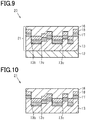
- a second embodiment of the transfer sheet, the color developing sheet, the color developing article, and the transfer method will be described with reference to Figs. 9 and 10 .
- differences between the second embodiment and the first embodiment mainly will be described, and the same components as in the first embodiment are given the same reference numerals and will not be described.
- a transfer sheet 20 of the second embodiment includes a monolayer film layer 17 instead of the multilayer film layer 14 and includes a reflection layer 18 instead of the absorption layer 15. That is, the transfer sheet 20 includes the peelable substrate 12, the resin layer 13, the monolayer film layer 17, the reflection layer 18, and the adhesive layer 16 in this order. Among these, the resin layer 13, the monolayer film layer 17, the reflection layer 18, and the adhesive layer 16 constitute a color developing sheet 21.
- the uneven structure of the resin layer 13 can be either the first structure or the second structure described in the first embodiment.
- Figs. 9 and 10 show, as an example, a configuration in which the resin layer 13 has the uneven structure of the second structure.
- the peelable substrate 12, the resin layer 13, and the adhesive layer 16 of the second embodiment have the same configuration as in the first embodiment.
- the monolayer film layer 17 covers the surface of the resin layer 13, and has a surface shape that follows the uneven structure of the resin layer 13.
- the monolayer film layer 17 is a layer composed of a monolayer thin film made of a dielectric.
- the wavelength range of the reflected light due to the monolayer thin film interference does not have a peak as sharp as that of the wavelength range of the reflected light due to multilayer film interference.
- the monolayer film layer 17 is designed so that the wavelength range of the reflected light includes a wavelength range at the end of the visible range and a portion outside the end of the visible range, for example, a wavelength range from a short wavelength range of the visible range to part of the ultraviolet range, an observer can visually recognize, as the reflected light from the monolayer film layer 17, a specific color corresponding to the short wavelength range of the visible range.
- the material and thickness of the monolayer film layer 17 may be selected according to a desired color to be developed on the color developing sheet 21.
- the monolayer film layer 17 may be made of, for example, any material selected from an inorganic oxide, an inorganic nitride, and an inorganic oxynitride.
- the thickness of the monolayer film layer 17 is selected, for example, from the range of 10 nm or more and 1000 nm or less.
- the reflection layer 18 is in contact with the monolayer film layer 17 on a surface of the monolayer film layer 17 opposite to that in contact with the resin layer 13.
- the reflection layer 18 reflects light transmitted through the monolayer film layer 17.
- a higher light reflectance is more preferable, and the monolayer film layer 17 and the reflection layer 18 are preferably configured such that specular reflection occurs at a high rate at the interface between these layers.
- it is preferable that light transmission through the reflection layer 18 is low and reflection of light at the interface between the monolayer film layer 17 and the reflection layer 18 is high and that the surface of the reflection layer 18 has a metallic luster.
- a refractive index n2 of the reflection layer 18 is preferably higher than a refractive index n1 of the monolayer film layer 17, and an extinction coefficient k1 of the monolayer film layer 17 is preferably 1 or less and an extinction coefficient k2 of the reflection layer 18 is preferably larger than 1.
- light that is transmitted through the monolayer film layer 17 and enters the reflection layer 18 is absorbed by the reflection layer 18, and as a result, the color visually recognized is less affected by the reflection at an interface between the reflection layer 18 and the adhesive layer 16 or an interface between the adhesive layer 16 and the adherend 31, which is preferable.
- the reflection layer 18 preferably has a lower visible light transmittance than the monolayer film layer 17, and preferably has a visible light transmittance of 30% or less. With this configuration, a high reflectance is obtained at the interface between the monolayer film layer 17 and the reflection layer 18, and light that is transmitted through the monolayer film layer 17 and enters the reflection layer 18 is absorbed by the reflection layer 18; thus, the reflected light from the color developing sheet 21 has more vivid color.
- the reflection layer 18 If the reflection layer 18 is not provided, the reflected light due to the thin film interference from the monolayer film layer 17 has a lower intensity than the reflected light due to multilayer film interference from the multilayer film layer 14 of the first embodiment.
- the reflection layer 18 When the reflection layer 18 is laminated on the monolayer film layer 17, the reflected light has a higher intensity, leading to an improvement in the visibility of the reflected light, i.e., the visibility of a specific color due to the thin film interference.
- the reflection layer 18 is preferably made of a metal material.
- a preferable configuration of the monolayer film layer 17 and the reflection layer 18 include a configuration in which the monolayer film layer 17 is made of titanium oxide and the reflection layer 18 is made of titanium and a configuration in which the monolayer film layer 17 is made of zirconium oxide and the reflection layer 18 is made of zirconium.
- the reflection layer 18 has a thickness, for example, in the range of 10 nm or more and 1000 nm or less.
- the monolayer film layer 17 and the reflection layer 18 are formed by using a known thin film formation technique such as sputtering, vacuum deposition, or an atomic layer deposition method according to the material.
- a method of transferring the color developing sheet 21 from the transfer sheet 20 to the adherend 31 is the same as the transfer method of the first embodiment. That is, the transfer sheet 20 is placed on the surface of the adherend 31 so that the adhesive layer 16 is in contact with the adherend 31, and the transfer sheet 20 is subjected to application of heat and pressure. Thus, the adhesive layer 16 is adhered to the surface of the adherend 31. Then, in the transfer sheet 20, the peelable substrate 12 is peeled off from the resin layer 13. In this manner, the color developing sheet 21 is transferred from the transfer sheet 20 to the adherend 31 to form a color developing article.
- the surface of the resin layer 13 opposite to the surface having the uneven structure constitutes the outermost surface of the color developing sheet 21, and is exposed to the outside air.
- the adhesive layer 16 constitutes the outermost surface of the color developing sheet 21 on the side opposite to the above-described outermost surface of the color developing sheet 21 constituted by the resin layer 13, and the adhesive layer 16 is in contact with the adherend 31.
- the color developing sheet 21 is observed from a side of the monolayer film layer 17 on which the resin layer 13 is located.
- light rays reflected at the front and rear surfaces of the monolayer film layer 17 interfere with each other and change the traveling direction due to the irregular uneven portion on the outermost surface of the monolayer film layer 17; thus, light in a specific wavelength range is emitted in a wide angular range.
- the peelable substrate 12 and the resin layer 13 are configured to be peelable from each other, and during transfer of the color developing sheet 21, only the peelable substrate 12 is peeled off.
- the color developing sheet 21 one of the uneven structures on the front and rear surfaces of the monolayer film layer 17 that is located closer to the resin layer 13, i.e., the uneven structure constituting the surface of the monolayer film layer 17 located closer to an observer, is covered with the resin layer 13.
- the color developing sheet 21 does not have the peelable substrate 12 which is the substrate used during production of the transfer sheet.
- the color developing sheet 21 is increased in flexibility and reduced in thickness.
- the transfer sheet 20 and the color developing sheet 21 include the monolayer film layer 17 composed of the monolayer thin film, as a layer that is laminated on the resin layer 13 and which exhibits structural colors.
- a smaller number of steps are required to produce the transfer sheet 20 and the color developing sheet 21 than for the configuration in which, as in the first embodiment, the transfer sheet 10 and the color developing sheet 11 include the multilayer film layer 14 composed of the plurality of thin films. This improves productivity of the transfer sheet 20 and the color developing sheet 21.
- the monolayer film layer 17 is the thin film layer
- the reflection layer 18 is the low transmission layer.
- the second embodiment can achieve the following effects.
- the absorption layer 15 when the absorption layer 15 is configured to have light absorption properties of not absorbing all light in the visible range but absorbing at least part of the light transmitted through the multilayer film layer 14, the absorption layer 15 achieves the effect of preventing reduction in the visibility of the color due to the reflected light, as compared with a configuration provided with no layer having such light absorption properties.
- the absorption layer 15 may be a layer containing a pigment of a color corresponding to the wavelength range of light transmitted through the multilayer film layer 14.
- the absorption layer 15 is a black layer containing a black pigment
- the absorption layer 15 requires no color adjustment or the like according to the wavelength range of the transmitted light, and the absorption layer 15 absorbs light in a wide wavelength range; thus, reduction in the visibility of the color due to the reflected light can be easily and suitably prevented.
- the monolayer film layer 17 and the reflection layer 18 are required to be configured to have a high reflectance for light in at least part of the wavelength range of light reflected at the interface between the monolayer film layer 17 and the reflection layer 18.
- the configuration having a high reflectance for light in part of the wavelength range of the reflected light also achieves the effect of increasing the intensity of the reflected light, as compared with a configuration having a low reflectance for light in the entire wavelength range of the reflected light.
- the monolayer film layer 17 and the reflection layer 18 are preferably configured such that for light in the at least part of the wavelength range, the refractive index n2 of the reflection layer 18 is higher than the refractive index n1 of the monolayer film layer 17, and the extinction coefficient k1 of the monolayer film layer 17 is 1 or less and the extinction coefficient k2 of the reflection layer 18 is larger than 1.
- the method of transferring the color developing sheets 11 and 21 is not limited to such thermal transfer, and may be another transfer method such as hydraulic transfer. That is, the adhesive layer 16 may not necessarily have the property of exhibiting adhesiveness by being heated, and, for example, the adhesive layer 16 may be adhered to the adherend 31 by application of only pressure or by irradiation with ultraviolet light.
- the transfer sheet and the color developing sheet may include the multilayer film layer 14 as the thin film layer and include the reflection layer 18 as the low transmission layer.
- the thin film layer may be composed of a plurality of thin films.
- the transfer sheets 10 and 20 and the color developing sheets 11 and 21 may include, in addition to the layers described in the above embodiments, a layer for improving adhesion between the layers, a layer having an ultraviolet absorption function, or the like.
- the figure that constitutes the pattern composed of the projection 13a in the first structure of the uneven structure, and the pattern composed of the first projection element 13Ea in the second structure of the uneven structure is not limited to a rectangle.
- the figure that constitutes these patterns may be an ellipse or the like.
- the figure is a shape element having a shape in which the length in the second direction Dy is equal to or greater than the length in the first direction Dx.
- the length d1 in the first direction Dx and the length d2 in the second direction Dy of the shape element need to satisfy the various conditions described for the first structure.
- the projection that constitutes the uneven structure of the resin layer 13 may have a configuration in which the width in the first direction Dx gradually decreases from the base portion toward the top. This configuration facilitates formation of the multilayer film layer 14 or the monolayer film layer 17 on the projection.
- the length d1 and the length d3 in the first direction Dx are defined by a pattern composed of the bottom surface of the projection.
Landscapes
- Physics & Mathematics (AREA)
- General Physics & Mathematics (AREA)
- Optics & Photonics (AREA)
- Diffracting Gratings Or Hologram Optical Elements (AREA)
- Laminated Bodies (AREA)
- Optical Filters (AREA)
Abstract
Description
- The present invention relates to a color developing sheet that exhibits structural colors, a transfer sheet and a color developing article including the color developing sheet, and a method of transferring the color developing sheet.
- Structural colors that are often observed as the colors of organisms in nature such as morpho butterflies are visually recognized due to the effects of optical phenomena such as diffraction, interference, and scattering of light caused by the fine structure of objects. For example, structural colors due to multilayer film interference are generated by interference of light reflected at interfaces of adjacent thin films. Multilayer film interference is one of the principles of color development morpho butterfly wings. In morpho butterfly wings, a fine uneven structure on the surface of the wings causes scattering and diffraction of light in addition to multilayer film interference; thus, a vivid blue color is visually recognized in a wide observation angular range.
- As a structure that artificially reproduces structural colors such as in morpho butterfly wings, as described in
PTL 1, a structure has been proposed in which a multilayer film layer is laminated on the surface of a substrate having unevenly arranged fine asperities. In a structure in which a multilayer film layer is laminated on a flat surface, the wavelength of visually recognized reflected light changes greatly depending on the observation angle; thus, the color visually recognized changes greatly depending on the observation angle. On the other hand, in the structure ofPTL 1, the irregular unevenness allows reflected light enhanced by interference to spread in multiple directions, leading to a gradual change in the color depending on the observation angle. This achieves a structure that exhibits a specific color in a wide observation angular range as in morpho butterfly wings. - [PTL 1]
JP 2005-153192 A - In the structure described in
PTL 1, the surface of the multilayer film layer has an uneven portion that follows the uneven portion of the substrate, and the surface of the multilayer film layer constitutes the surface of the structure. That is, due to exposure of the uneven structure, when a physical or chemical stress is applied to the structure from the outside, the uneven structure can be easily deformed. Deformation of the uneven structure changes the optical path length of light reflected at the multilayer film and reduces the effect of diffusing the reflected light in multiple directions; thus, the structure is less likely to provide the desired color development. - An object of the present invention is to provide a transfer sheet, a color developing sheet, a color developing article, and a transfer method capable of preventing deformation of an uneven structure having an optical function.
- A transfer sheet for solving the above problem is a transfer sheet including: a peelable substrate; an uneven layer that is in contact with the peelable substrate so as to be peelable and has an uneven structure on a surface opposite to a surface in contact with the peelable substrate; a thin film layer that is located on the uneven structure and has a surface shape following the uneven structure and from which reflected light enhanced by interference emerges; a low transmission layer that is located on a side of the thin film layer opposite to the uneven layer and has a lower transmittance for light in a visible range than the thin film layer; and an adhesive layer that is located on a side of the low transmission layer opposite to the thin film layer, wherein: a projection included in the uneven structure has a shape having one or more steps from a plane in which a base portion of the projection is located; when viewed in a direction perpendicular to the surface of the uneven layer, a pattern composed of the projection includes a pattern composed of a group of a plurality of shape elements in each of which a length in a first direction is equal to or less than a subwavelength and a length in a second direction orthogonal to the first direction is equal to or greater than the length in the first direction; and in the plurality of shape elements, a standard deviation of the length in the second direction is larger than a standard deviation of the length in the first direction.
- According to the above configuration, the uneven portion on one surface of the thin film layer is covered with the uneven layer, and the uneven portion on the other surface of the thin film layer is covered with the low transmission layer and the adhesive layer. Thus, as compared with a configuration in which the uneven structure of the thin film layer is exposed, deformation of the uneven structure can be prevented. Furthermore, the peelable substrate and the uneven layer are in contact with each other so as to be peelable from each other. Accordingly, after the transfer sheet is bonded to an adherend, the peelable substrate can be peeled off. Thus, the color developing sheet transferred to the adherend is increased in flexibility, and the color developing sheet having a small thickness can be easily formed.
- A color developing sheet for solving the above problem is a color developing sheet including: an uneven layer having a surface having an uneven structure; a thin film layer that is located on the uneven structure and has a surface shape following the uneven structure and from which reflected light enhanced by interference emerges; a low transmission layer that is located on a side of the thin film layer opposite to the uneven layer and has a lower transmittance for light in a visible range than the thin film layer; and an adhesive layer that is located on a side of the low transmission layer opposite to the thin film layer, wherein: a projection included in the uneven structure has a shape having one or more steps from a plane in which a base portion of the projection is located; when viewed in a direction perpendicular to the surface of the uneven layer, a pattern composed of the projection includes a pattern composed of a group of a plurality of shape elements in each of which a length in a first direction is equal to or less than a subwavelength and a length in a second direction orthogonal to the first direction is equal to or greater than the length in the first direction; and in the plurality of shape elements, a standard deviation of the length in the second direction is larger than a standard deviation of the length in the first direction.
- According to the above configuration, the uneven portion on one surface of the thin film layer is covered with the uneven layer, and the uneven portion on the other surface of the thin film layer is covered with the low transmission layer and the adhesive layer. Thus, as compared with a configuration in which the uneven structure of the thin film layer is exposed, deformation of the uneven structure can be prevented.
- A color developing article for solving the above problem is a color developing article including: the color developing sheet; and an adherend to which the color developing sheet is bonded and that is in contact with the adhesive layer.
- According to the above configuration, in the color developing sheet, deformation of the uneven structure is prevented, leading to a color developing article including a color developing sheet that suitably provides the desired color development.
- A transfer method for solving the above problem is a transfer method including: placing the transfer sheet on a surface of an adherend and adhering the adhesive layer to the adherend; and peeling off the peelable substrate from the uneven layer.
- According to the above transfer method, since only the peelable substrate is peeled off while leaving the uneven layer, deformation of the uneven structure of the transferred sheet can be prevented without separately forming a layer for protecting the uneven structure of the thin film layer.
- According to the present invention, in a color developing sheet, deformation of an uneven structure having an optical function can be prevented.
-
-
Fig. 1 is a view showing a cross-sectional structure of a transfer sheet according to a first embodiment of the transfer sheet. -
Fig. 2A is a view showing a planar structure of an uneven structure of a first structure in the transfer sheet of the first embodiment. -
Fig. 2B is a view showing a cross-sectional structure of the uneven structure of the first structure in the transfer sheet of the first embodiment. -
Fig. 3 is a view showing a cross-sectional structure having another configuration of the transfer sheet of the first embodiment. -
Fig. 4A is a view showing a planar structure of an uneven structure composed of only second projection elements in the transfer sheet of the first embodiment. -
Fig. 4B is a view showing a cross-sectional structure of the uneven structure composed of only the second projection elements in the transfer sheet of the first embodiment. -
Fig. 5A is a view showing a planar structure of an uneven structure of a second structure in the transfer sheet of the first embodiment. -
Fig. 5B is a view showing a cross-sectional structure of the uneven structure of the second structure in the transfer sheet of the first embodiment. -
Fig. 6 is a view showing a transfer method using the transfer sheet of the first embodiment and showing a step of bonding the transfer sheet to an adherend. -
Fig. 7 is a view showing a color developing article which is an adherend to which a color developing sheet of the first embodiment is transferred. -
Fig. 8 is a view showing a cross-sectional structure of the color developing sheet of the first embodiment. -
Fig. 9 is a view showing a cross-sectional structure of a transfer sheet according to a second embodiment of the transfer sheet. -
Fig. 10 is a view showing a cross-sectional structure of a color developing sheet of the second embodiment. - A first embodiment of a transfer sheet, a color developing sheet, a color developing article, and a transfer method will be described with reference to
Figs. 1 to 8 . The wavelength range of incident light and reflected light on the color developing sheet is not particularly limited, and the following embodiments will describe, as an example, a color developing sheet for light in the visible range. In the following description, light in the visible range refers to light in the wavelength range of 360 nm or more and 830 nm or less. - First, a configuration of the transfer sheet will be described. The transfer sheet is a sheet used to bond a color developing sheet to an adherend. Specifically, the transfer sheet is used to transfer a color developing sheet provided in the transfer sheet to an adherend.
- As shown in
Fig. 1 , atransfer sheet 10 includes apeelable substrate 12, aresin layer 13, which is an example of an uneven layer, amultilayer film layer 14, anabsorption layer 15, and anadhesive layer 16. Among these, theresin layer 13, themultilayer film layer 14, theabsorption layer 15, and theadhesive layer 16 constitute acolor developing sheet 11. That is, thetransfer sheet 10 is a laminate of thepeelable substrate 12 and thecolor developing sheet 11. - The
peelable substrate 12 is a flat layer, and thepeelable substrate 12 is in contact with theresin layer 13 so as to be peelable. Theresin layer 13 has an uneven structure on a surface opposite to a surface in contact with thepeelable substrate 12. The uneven structure of theresin layer 13 is composed of a plurality ofprojections 13a that are irregularly arranged and recesses 13b which are regions between the plurality ofprojections 13a. - The
peelable substrate 12 is, for example, a synthetic quartz substrate or a film made of a resin such as polyethylene terephthalate (PET). In terms of increasing flexibility of thetransfer sheet 10, thepeelable substrate 12 is preferably made of a resin. Thepeelable substrate 12 has a thickness, for example, in the range of 10 µm or more and 100 µm or less. - The
resin layer 13 is made of a resin that transmits light in the visible range, i.e., a resin that is transparent to light in the visible range. The resin constituting theresin layer 13 is, for example, a thermoplastic resin. - The
peelable substrate 12 is configured to be peelable from theresin layer 13, for example, by selecting the materials of thepeelable substrate 12 and theresin layer 13 to achieve low adhesion between thepeelable substrate 12 and theresin layer 13. - The
peelable substrate 12 may be configured to be peelable from theresin layer 13, for example, by using thepeelable substrate 12 or theresin layer 13 containing a component such as silicone oil or a fluorine compound that functions as a release agent. Alternatively, thepeelable substrate 12 may be configured to be peelable from theresin layer 13, for example, by providing a release layer containing a release agent between thepeelable substrate 12 and theresin layer 13. In a case where thepeelable substrate 12 is peeled off at an interface between thepeelable substrate 12 and the release layer, the release layer and theresin layer 13 constitute the uneven layer. - It is preferable that the peelability of the
peelable substrate 12 from theresin layer 13 is exhibited by heating or that peeling of thepeelable substrate 12 from theresin layer 13 is accelerated by heating. For example, in a case where theresin layer 13 is made of a thermoplastic resin, softening of theresin layer 13 by heating accelerates peeling of thepeelable substrate 12 from theresin layer 13. - The
multilayer film layer 14 covers the surface of theresin layer 13, and has a surface shape that follows the uneven structure of theresin layer 13. Themultilayer film layer 14 is a laminate of a plurality of thin films, and has a structure in which high refractive index layers 14a and low refractive index layers 14b are alternately laminated. The highrefractive index layer 14a and the lowrefractive index layer 14b are each a dielectric thin film. The highrefractive index layer 14a has a higher refractive index than the lowrefractive index layer 14b. For example, the highrefractive index layer 14a is a layer in contact with theresin layer 13, and the lowrefractive index layer 14b is a layer in contact with theabsorption layer 15. On theprojection 13a and therecess 13b of theresin layer 13, themultilayer film layer 14 has the same configuration, that is, the material, thickness, and the order of lamination of the layers constituting themultilayer film layer 14 are the same. - When light is incident on the
multilayer film layer 14, light rays reflected at each interface between the highrefractive index layer 14a and the lowrefractive index layer 14b of themultilayer film layer 14 interfere with each other and change the traveling direction due to the irregular uneven portion on an outermost surface of themultilayer film layer 14; thus, light in a specific wavelength range is emitted in a wide angular range. The specific wavelength range strongly emitted as reflected light is determined by the material and thickness of the highrefractive index layer 14a and the lowrefractive index layer 14b, as well as the width, height, and arrangement of the uneven portion. - The high
refractive index layer 14a and the lowrefractive index layer 14b are made of a material that transmits light in the visible range, i.e., a material that is transparent to light in the visible range. The material of these layers is not limited, as long as the highrefractive index layer 14a has a higher refractive index than the lowrefractive index layer 14b. The greater the difference in the refractive index between the highrefractive index layer 14a and the lowrefractive index layer 14b, the greater the intensity of reflected light can be obtained with a smaller number of laminations. From this viewpoint, for example, in a case where the highrefractive index layer 14a and the lowrefractive index layer 14b are made of an inorganic material, it is preferable that the highrefractive index layer 14a is made of titanium dioxide (TiO2) and the lowrefractive index layer 14b is made of silicon dioxide (SiO2). However, the highrefractive index layer 14a and the lowrefractive index layer 14b may be made of an organic material. - The thickness of each of the high
refractive index layer 14a and the lowrefractive index layer 14b may be designed using a transfer matrix method or the like according to a desired color to be developed on thecolor developing sheet 11. For example, in the case of thecolor developing sheet 11 that exhibits a blue color, the highrefractive index layer 14a made of TiO2 preferably has a thickness of approximately 40 nm, and the lowrefractive index layer 14b made of SiO2 preferably has a thickness of approximately 75 nm. -
Fig. 1 shows, as an example, themultilayer film layer 14 composed of 10 layers in which the high refractive index layers 14a and the low refractive index layers 14b are alternately laminated in this order from a position close to theresin layer 13. The number of layers and the order of lamination in themultilayer film layer 14 are not limited thereto, as long as the high refractive index layers 14a and the low refractive index layers 14b are designed to provide reflected light in a desired wavelength range. For example, themultilayer film layer 14 may be configured such that on the lowrefractive index layer 14b in contact with theresin layer 13, the high refractive index layers 14a and the low refractive index layers 14b are alternately laminated. The layer in contact with theabsorption layer 15 may be either the highrefractive index layer 14a or the lowrefractive index layer 14b. Furthermore, the layer in contact with theresin layer 13 and the layer in contact with theabsorption layer 15 may be made of the same material, as long as the low refractive index layers 14b and the high refractive index layers 14a are alternately laminated. Themultilayer film layer 14 may be composed of a combination of three or more layers having different refractive indices. - In short, the
multilayer film layer 14 may be configured such that adjacent layers have different refractive indices, and so that, of light incident on themultilayer film layer 14, the reflectance of light in a specific wavelength range is higher than the reflectance of light in other wavelength ranges. - The
absorption layer 15 and theadhesive layer 16 are located on a side of themultilayer film layer 14 opposite to theresin layer 13. Theabsorption layer 15 covers the uneven portion on the outermost surface of themultilayer film layer 14. Theabsorption layer 15 has light absorption properties of absorbing light transmitted through themultilayer film layer 14. Theabsorption layer 15 has a lower visible light transmittance than themultilayer film layer 14. For example, theabsorption layer 15 is a layer containing a material such as a light absorber or a black pigment that absorbs light in the visible range. Specifically, theabsorption layer 15 is preferably a layer obtained by mixing, with a resin, a black inorganic pigment such as carbon black, titanium black, black iron oxide, or black composite oxide. Theabsorption layer 15 has a thickness, for example, in the range of 1 µm or more and 10 µm or less. - The
adhesive layer 16 is in contact with theabsorption layer 15 on the opposite surface of theabsorption layer 15 to that in contact with themultilayer film layer 14, and constitutes the outermost surface of thetransfer sheet 10 and the outermost surface of thecolor developing sheet 11. Theadhesive layer 16 has adhesion properties that are exhibited by heating. In other words, theadhesive layer 16 has heat sealability. Examples of a heat-sealing agent that constitutes theadhesion layer 16 include thermoplastic resins such as polyethylene, polyvinyl acetate, acrylic resins, polyamide, polyester, polypropylene, and polyurethane. Theadhesive layer 16 has a thickness, for example, in the range of 10 µm or more and 100 µm or less. - The uneven structure of the
resin layer 13 will be described in detail. The uneven structure can be either of two structures, i.e., a first structure and a second structure. Each of the two structures will be described.Fig. 1 shows acolor developing sheet 11A and atransfer sheet 10A having an uneven structure of the first structure. - The uneven structure of the first structure will be described in detail with reference to
Figs. 2A and 2B. Fig. 2A is a plan view of theresin layer 13 viewed in a direction perpendicular to the surface of theresin layer 13, andFig. 2B is a view showing a cross-sectional structure of theresin layer 13 taken along line II-II inFig. 2A . InFig. 2A , theprojections 13a constituting the uneven structure is indicated by dots. - As shown in
Fig. 2A , a first direction Dx and a second direction Dy are directions in a plane in which theresin layer 13 extends, and the first direction Dx is orthogonal to the second direction Dy. The plane is a surface orthogonal to the thickness direction of theresin layer 13. - When the
resin layer 13 is viewed in the direction perpendicular to the surface of theresin layer 13, a pattern composed of theprojection 13a is a pattern composed of a set of a plurality of rectangles R indicated by dashed lines. The rectangle R is an example of a shape element. The rectangle R has a shape extending in the second direction Dy, and in the rectangle R, a length d2 in the second direction Dy is equal to or greater than a length d1 in the first direction Dx. The plurality of rectangles R are arranged so as not to overlap with each other in either the first direction Dx or the second direction Dy. - In the plurality of rectangles R, the length d1 in the first direction Dx is constant. The plurality of rectangles R are arranged in the first direction Dx at an arrangement interval of length d1, that is, the rectangles R are arranged with a period of length d1.
- On the other hand, in the plurality of rectangles R, the length d2 in the second direction Dy is not constant, and the length d2 of the rectangle R is a value selected from a population having a predetermined standard deviation. This population preferably follows a normal distribution. For example, the pattern composed of the plurality of rectangles R is formed, for example, by temporarily placing, in a predetermined region, a plurality of rectangles R having the length d2 distributed with a predetermined standard deviation and then determining according to a predetermined probability whether to actually arrange each of the rectangles R to set a region in which the rectangle R is arranged and a region in which no rectangle R is arranged. In order to efficiently scatter the reflected light from the
multilayer film layer 14, the length d2 preferably has a distribution with an average value of 4.13 µm or less and a standard deviation of 1 µm or less. - The region in which the rectangle R is arranged is a region in which the
projection 13a is arranged. When adjacent rectangles R are in contact with each other, asingle projection 13a is arranged in a single region obtained by combining regions in which the rectangles R are arranged. In such a configuration, the length of theprojection 13a in the first direction Dx is an integral multiple of the length d1 of the rectangle R. - In order to prevent occurrence of a rainbow spectrum due to the uneven portion of the
multilayer film layer 14, the length d1 of the rectangle R in the first direction Dx is set to be equal to or less than the wavelength of light in the visible range. In other words, the length d1 is a length equal to or less than a subwavelength, i.e., a length equal to or less than the wavelength range of incident light. That is, the length d1 is preferably 830 nm or less, and more preferably 700 nm or less. Furthermore, the length d1 is preferably smaller than the peak wavelength of light in the specific wavelength range reflected at themultilayer film layer 14. For example, when a blue color is to be developed on thecolor developing sheet 11, the length d1 is preferably about 300 nm, when a green color is to be developed on thecolor developing sheet 11, the length d1 is preferably about 400 nm, and when a red color is to be developed on thecolor developing sheet 11, the length d1 is preferably about 460 nm. - In order to allow the reflected light from the
multilayer film layer 14 to be widely spread, that is, in order to enhance the scattering effect of the reflected light, the uneven structure preferably has many projecting and recessed portions. When viewed in the direction perpendicular to the surface of theresin layer 13, the ratio of the area of theprojection 13a per unit area is preferably in the range of 40% or more and 60% or less. For example, when viewed in the direction perpendicular to the surface of theresin layer 13, the ratio of the area of theprojection 13a to the area of therecess 13b per unit area is preferably 1:1. - As shown in
Fig. 2B , a height h1 of theprojection 13a is constant, and theprojection 13a has a shape having a single step from a plane in which a base portion of theprojection 13a is located. The height h1 of theprojection 13a may be set according to a desired color to be developed on thecolor developing sheet 11, i.e., the wavelength range of light desired to be reflected at thecolor developing sheet 11. When the height h1 of theprojection 13a is larger than the height of the surface roughness of themultilayer film layer 14 on each of theprojection 13a and therecess 13b, the scattering effect of the reflected light is obtained. - However, in order to prevent light interference caused by reflection on the uneven portion of the
multilayer film layer 14, the height h1 is preferably 1/2 or less of the wavelength of light in the visible range, that is, the height h1 is preferably 413 nm or less. In order to prevent light interference, the height h1 is more preferably 1/2 or less of the peak wavelength of light in the specific wavelength range reflected at themultilayer film layer 14. - If the height h1 is excessively large, the
multilayer film layer 14 has an excessively high scattering effect of the reflected light, and the reflected light tends to have a low intensity. Thus, when the reflected light is light in the visible range, the height h1 is preferably in the range of 10 nm or more and 200 nm or less. For example, in a developingsheet 11 that exhibits a blue color, the height h1 is preferably in the range of approximately 40 nm or more and 130 nm or less in order to allow light to be effectively spread, and the height h1 is preferably 100 nm or less in order to prevent the scattering effect from becoming too high. - The rectangles R may be arranged so that two rectangles R arranged in the first direction Dx partially overlap with each other to constitute the pattern of the
projection 13a. That is, the plurality of rectangles R may be arranged in the first direction Dx at an arrangement interval smaller than the length d1, and the arrangement interval of the rectangles R may not necessarily be constant. In a portion in which rectangles R overlap with each other, asingle projection 13a is located in a single region obtained by combining regions in which the rectangles R are arranged. In this case, the length of theprojection 13a in the first direction Dx is different from an integral multiple of the length d1 of the rectangle R. The length d1 of the rectangle R may not necessarily be constant, as long as the length d2 is equal to or greater than the length d1 of the rectangle R and the standard deviation of the length d2 is larger than the standard deviation of the length d1 in the plurality of rectangles R. This configuration also allows themultilayer film layer 14 to have the scattering effect of the reflected light. -
Fig. 3 shows acolor developing sheet 11B and atransfer sheet 10B having an uneven structure of the second structure. The configuration in which theresin layer 13 has the uneven structure of the first structure is the same as the configuration in which theresin layer 13 has the uneven structure of the second structure, except for the configuration of the uneven structure of thecolor developing sheet 11 and thetransfer sheet 10. - A
projection 13c that constitutes the uneven structure of the second structure has a structure in which a first projection element and a second projection element are superimposed in the thickness direction of theresin layer 13. The first projection element has the same structure as theprojection 13a of the first structure, and the second projection element extends in a strip shape. - In the
color developing sheet 11 having the uneven structure of the first structure, the scattering effect of the reflected light achieves a gradual change in the color visually recognized depending on the observation angle; however, the vividness of the color visually recognized is reduced due to a decrease in the intensity of the reflected light caused by scattering. Depending on the application or the like of the color developing sheet, in some cases, the sheet is required to allow more vivid color to be observed in a wide observation angular range. The second projection element of the second structure is arranged so that the incident light is strongly diffracted in a specific direction. Thus, a light scattering effect based on the first projection element and a light diffraction effect based on the second projection element achieve a color developing sheet that allows more vivid color to be observed in a wide observation angular range. - A configuration of the second projection element will be described with reference to
Figs. 4A and 4B. Fig. 4A is a plan view of an uneven structure composed of only the second projection elements, andFig. 4B is a view showing a cross-sectional structure taken along line IV-IV inFig. 4A . InFig. 4A , the second projection element is indicated by dots. - As shown in
Fig. 4A , in a plan view, a second projection element 13Eb has a strip shape extending in the second direction Dy with a constant width, and a plurality of second projection elements 13Eb are arranged at intervals in the first direction Dx. In other words, a pattern composed of the second projection element 13Eb is a pattern composed of a plurality of strip-shaped regions that extend in the second direction Dy and are arranged in the first direction Dx. A length d3 of the second projection element 13Eb in the first direction Dx may be the same or different from the length d1 of the rectangle R that determines a pattern of the first projection element. - An arrangement interval de of the second projection elements 13Eb in the first direction Dx, i.e., an arrangement interval of the strip-shaped regions in the first direction Dx, is set so that at least part of the reflected light from the surface of the uneven structure composed of the second projection elements 13Eb is observed as first-order diffracted light. The first-order diffracted light is, in other words, diffracted light whose diffraction order m is 1 or -1. That is, the arrangement interval de satisfies de ≥ λ(sinθ + sincp), where θ represents the incident angle of the incident light, ϕ represents the reflection angle of the reflected light, and λ represents the wavelength of the diffracted light. For example, when visible light in which λ = 360 nm is targeted, the arrangement interval de of the second projection elements 13Eb may be 180 nm or more, that is, the arrangement interval de may be 1/2 or more of the minimum wavelength in the wavelength range of the incident light. The arrangement interval de is a distance between the sides of two adjacent second projection elements 13Eb in the first direction Dx, and is a distance between the sides located on the same side of the second projection elements 13Eb in the first direction Dx.
- The periodicity of the pattern composed of the second projection element 13Eb is reflected in the periodicity of the uneven structure of the
resin layer 13. When the arrangement interval de of the plurality of second projection elements 13Eb is constant, due to a diffraction phenomenon from the outermost surface of themultilayer film layer 14, reflected light of a specific wavelength is emitted at a specific angle from themultilayer film layer 14. The light generated due to diffraction has a much higher reflection intensity than the reflected light generated due to the light scattering effect based on the first projection element; thus, light having a luster such as a metallic luster is visually recognized. However, diffraction causes dispersion of light, and the color visually recognized changes according to the change in the observation angle. - Thus, for example, even when the first projection element is designed to have a structure that allows the color developing sheet to exhibit a blue color, if the arrangement interval de of the second projection elements 13Eb is a constant value in the range of approximately 400 nm to 5 µm, light in the range from strong green to red may be observed by surface reflection due to diffraction depending on the observation angle. On the other hand, for example, if the arrangement interval de of the second projection elements 13Eb is as large as approximately 50 µm, light in the visible range is diffracted in a smaller angular range and thus a change in the color due to diffraction is less likely to be visually recognized; however, light having a luster such as a metallic luster is observed only at a specific observation angle.
- Thus, when the arrangement interval de is not set to a constant value and the pattern of the second projection element 13Eb is set to a pattern in which a plurality of periodic structures having different periods are superimposed, light of a plurality of wavelengths is mixed with the reflected light due to diffraction, and accordingly, dispersed light with high monochromaticity is less likely to be visually recognized. Thus, glossy and vivid color is observed in a wide observation angular range. In this case, the arrangement interval de is selected, for example, from the range of 360 nm or more and 5 µm or less, and the average value of the arrangement intervals de of the plurality of second projection elements 13Eb may be 1/2 or more of the minimum wavelength in the wavelength range of the incident light.
- However, as the arrangement interval de has a larger standard deviation, the arrangement of the second projection elements 13Eb becomes more irregular and the scattering effect becomes dominant, and accordingly, strong reflection due to diffraction is less likely to be achieved. Thus, the arrangement interval de of the second projection elements 13Eb is preferably determined according to the angular range in which light is spread due to the light scattering effect based on the first projection element so that the reflected light due to diffraction is emitted in approximately the same angular range as the angular range for the above scattered light. For example, when blue reflected light is emitted with a spread within a range of ±40° with respect to the incident angle, the arrangement interval de in the pattern of the second projection element 13Eb is set to have an average value in the range of approximately 1 µm or more and 5 µm or less, and have a standard deviation of approximately 1 µm. Thus, reflected light is generated due to diffraction in approximately the same angular range as the angular range in which light is spread due to the light scattering effect based on the first projection element.
- That is, unlike a structure for extracting light in a specific wavelength range after diffraction, the uneven structure based on the plurality of second projection elements 13Eb is a structure for allowing light in various wavelength ranges to emerge in a predetermined angular range by using diffraction due to dispersion of the arrangement interval de.
- In order to cause a longer-period diffraction phenomenon, the pattern of the second projection element 13Eb may be configured such that a unit region is a square region having a side length in the range of 10 µm or more and 100 µm or less, and that the arrangement interval de in the pattern of the second projection element 13Eb for each unit region is set to have an average value in the range of approximately 1 µm or more and 5 µm or less, and have a standard deviation of approximately 1 µm. A plurality of unit regions may include a region in which the arrangement interval de is a constant value in the range of 1 µm or more and 5 µm or less. Even if there is a unit region in which the arrangement interval de is constant, when the arrangement interval de varies with a standard deviation of approximately 1 µm in any of unit regions adjacent to the unit region, an effect equivalent to that of the configuration in which the arrangement interval de varies in all the unit regions can be expected within the resolution of the human eye.
- The second projection element 13Eb shown in
Fig. 4A has a periodicity associated with the arrangement interval de only in the first direction Dx. The light scattering effect based on the first projection element mainly acts on the reflected light in a direction along the first direction Dx, but can also partially affect the reflected light in a direction along the second direction Dy, as viewed in a direction perpendicular to the outermost surface of themultilayer film layer 14. Thus, the second projection element 13Eb may have a periodicity also in the second direction Dy. That is, the pattern of the second projection element 13Eb may be a pattern in which a plurality of strip-shaped regions extending in the second direction Dy are arranged in each of the first direction Dx and the second direction Dy. - In such a pattern of the second projection element 13Eb, for example, the arrangement interval of the strip-shaped regions in the first direction Dx and the arrangement interval of the strip-shaped regions in the second direction Dy may vary with each average value being in the range of 1 µm or more and 100 µm or less. Depending on the difference between the effect of the light scattering effect based on the first projection element on the first direction Dx and the effect of the light scattering effect on the second direction Dy, the average value of the arrangement intervals in the first direction Dx may be different from the average value of the arrangement intervals in the second direction Dy, and the standard deviation of the arrangement interval in the first direction Dx may be different from the standard deviation of the arrangement interval in the second direction Dy.
- As shown in
Fig. 4B , a height h2 of the second projection element 13Eb needs to be larger than the height of the surface roughness of themultilayer film layer 14 on each of theprojection 13c and therecess 13b. However, as the height h2 is increased, the diffraction effect based on the second projection element 13Eb becomes dominant in the effect of the uneven structure on the reflected light, and accordingly, the light scattering effect based on the first projection element is less likely to be achieved. Thus, the height h2 is preferably approximately the same as the height h1 of the first projection element, and the height h2 may be the same as the height h1. For example, the height h1 of the first projection element and the height h2 of the second projection element 13Eb are preferably in the range of 10 nm or more and 200 nm or less. In a developingsheet 11 that exhibits a blue color, the height h1 of the first projection element and the height h2 of the second projection element 13Eb are preferably in the range of 10 nm or more and 130 nm or less. - The uneven structure of the second structure will be described in detail with reference to
Figs. 5A and 5B. Fig. 5A is a plan view of theresin layer 13 viewed in the direction perpendicular to the surface of theresin layer 13, andFig. 5B is a view showing a cross-sectional structure of theresin layer 13 taken along line V-V inFig. 5A . InFig. 5A , a pattern composed of the first projection element and a pattern composed of the second projection element are indicated by dots with different densities. - As shown in
Fig. 5A , when theresin layer 13 is viewed in the direction perpendicular to the surface of theresin layer 13, a pattern composed of theprojection 13c is a pattern in which a first pattern composed of first projection element 13Ea and a second pattern composed of the second projection element 13Eb are superimposed. That is, regions in which theprojection 13c is located include a region S1 that is composed of only the first projection element 13Ea, a region S2 in which the first projection element 13Ea and the second projection element 13Eb are superimposed, and a region S3 that is composed of only the second projection element 13Eb. InFig. 5A , the first projection element 13Ea and the second projection element 13Eb are superimposed so that the sides of the first projection element 13Ea and the second projection element 13Eb are aligned with each other in the first direction Dx. However, the configuration is not limited to this, and the sides of the first projection element 13Ea and the second projection element 13Eb may not necessarily be aligned with each other. - As shown in
Fig. 5B , in the region S1, the height of theprojection 13c is the height h1 of the first projection element 13Ea. In the region S2, the height of theprojection 13c is the sum of the height h1 of the first projection element 13Ea and the height h2 of the second projection element 13Eb. In the region S3, the height of theprojection 13c is the height h2 of the second projection element 13Eb. Thus, theprojection 13c has multi-stage shape in which the first projection element 13Ea and the second projection element 13Eb are superimposed in the height direction. The first projection element 13Ea has the predetermined height hi, and a projected image of the first projection element 13Ea in the thickness direction of theresin layer 13 constitutes the first pattern. The second projection element 13Eb has the predetermined height h2, and a projected image of the second projection element 13Eb in the thickness direction constitutes the second pattern. Theprojection 13c can be considered to have a structure in which the second projection element 13Eb is laminated on the first projection element 13Ea from the position of a base portion of theprojection 13c, or a structure in which the first projection element 13Ea is laminated on the second projection element 13Eb from the position of the base portion of theprojection 13c. - The pattern composed of the first projection element 13Ea and the pattern composed of the second projection element 13Eb may be arranged so that the first projection element 13Ea and the second projection element 13Eb are not superimposed. This structure also achieves the light diffusion effect based on the first projection element 13Ea and the light diffraction effect based on the second projection element 13Eb. However, when the first projection element 13Ea and the second projection element 13Eb are arranged so as not to be superimposed with each other, as compared with the first structure, the area of the region per unit area in which the first projection element 13Ea can be arranged is reduced, and accordingly, the light diffusion effect is reduced. Thus, in order to enhance the light diffusion effect based on the projection element 13Ea and the light diffraction effect based on the projection element 13Eb, as shown in
Fig. 5A , theprojection 13c preferably has a multi-stage shape in which the first projection element 13Ea and the second projection element 13Eb are superimposed. - A method of producing the
transfer sheet 10 will be described. - First, the
resin layer 13 is formed on thepeelable substrate 12. The method of forming the uneven structure of theresin layer 13 is, for example, a nanoimprint method. For example, when the uneven structure of theresin layer 13 is formed by a photo-nanoimprint method, a coating liquid containing the material of theresin layer 13 is applied to the surface of the mold having the uneven shape. The mold is formed by having the uneven portion reversed from the uneven portion to be informed. The mold is an example of an intaglio plate. As the material of theresin layer 13, a photocurable resin is used. The method of applying the coating liquid is not particularly limited, and may be a known coating method such as an ink jet method, a spray method, a bar coating method, a roll coating method, a slit coating method, or a gravure coating method. - Then, the
peelable substrate 12 is stacked on a surface of the layer made of the coating liquid, and while thepeelable substrate 12 and the mold are pressed against each other, the layer is irradiated with light from a side on which thepeelable substrate 12 is located or a side on which the mold is located. Subsequently, the mold is released from the layer made of cured resin and thepeelable substrate 12. Thus, the uneven shape of the mold is transferred to the resin to form theresin layer 13 whose surface has the uneven shape and form a laminate of thepeelable substrate 12 and theresin layer 13. The mold may be made of, for example, synthetic quartz or silicon, and is formed by a known microfabrication technique such as lithography using irradiation with light or a charged particle beam, or dry etching. - The coating liquid may be applied to the surface of the
peelable substrate 12, and while the mold is pressed against the layer made of the coating liquid on thepeelable substrate 12, the layer may be irradiated with light. Furthermore, instead of the photo-nanoimprint method, a thermal nanoimprint method may be used. - Subsequently, the layers that constitute the
multilayer film layer 14 are sequentially laminated on the surface of theresin layer 13 having the uneven shape. In a case where the highrefractive index layer 14a and the lowrefractive index layer 14b constituting themultilayer film layer 14 are made of an inorganic material, the highrefractive index layer 14a and the lowrefractive index layer 14b are each formed by using a known thin film formation technique such as sputtering, vacuum deposition, or an atomic layer deposition method. In a case where the highrefractive index layer 14a and the lowrefractive index layer 14b are made of an organic material, the highrefractive index layer 14a and the lowrefractive index layer 14b may be formed by a known technique such as self-organization. - Subsequently, the
absorption layer 15 is formed on the upper surface of themultilayer film layer 14. Theabsorption layer 15 may be formed, for example, by using a known coating method such as an ink jet method, a spray method, a bar coating method, a roll coating method, a slit coating method, or a gravure coating method. A coating liquid for forming theabsorption layer 15 may be mixed with a solvent, if necessary. The solvent may be a solvent that is compatible with the resin constituting theabsorption layer 15. Examples of the solvent include ethyl acetate, butyl acetate, ethylene glycol monomethyl ether, toluene, xylene, methylcyclohexane, ethylcyclohexane, acetone, methyl ethyl ketone, methyl isobutyl ketone, and diisobutyl ketone. - Subsequently, the
adhesion layer 16 is formed on the upper surface of theabsorption layer 15. Theadhesion layer 16 is formed, for example, by using a known coating method such as an ink jet method, a spray method, a bar coating method, a roll coating method, a slit coating method, or a gravure coating method. In this manner, thetransfer sheet 10 is formed. - A configuration of the
color developing sheet 11 and a color developing article will be described while explaining a method of transferring thecolor developing sheet 11 from thetransfer sheet 10 to an adherend. The color developing article is an article including an adherend and thecolor developing sheet 11. Thecolor developing sheet 11 may be used, for example, for the purpose of enhancing the designability of articles, or for the purpose of increasing the difficulty of counterfeiting articles. Thecolor developing sheet 11 may be used for both purposes. - As shown in
Fig. 6 , first, thetransfer sheet 10 is placed on a surface of anadherend 31 so that theadhesive layer 16 is in contact with theadherend 31, and thetransfer sheet 10 is subjected to application of heat and pressure. For example, a heated pressing member such as a stamp is pressed against thetransfer sheet 10 from a side opposite to theadherend 31 to apply heat and pressure to thetransfer sheet 10. Thus, theadhesive layer 16 exhibits adhesiveness, and theadhesive layer 16 is adhered to the surface of theadherend 31. That is, thetransfer sheet 10 is bonded to theadherend 31. While thetransfer sheet 10 is fixed to theadherend 31, thepeelable substrate 12 faces the outside. - The shape and material of the
adherend 31 are not particularly limited, and theadherend 31 may be, for example, a resin molded product such as a card or a three-dimensional object, or may be a piece of paper. In short, theadherend 31 needs to have a surface to which theadhesive layer 16 can be adhered. - As shown in
Fig. 7 , subsequently, in thetransfer sheet 10, thepeelable substrate 12 is peeled off from theresin layer 13. Thus, thecolor developing sheet 11 is transferred from thetransfer sheet 10 to theadherend 31. That is, acolor developing article 30 is formed in which thecolor developing sheet 11 is fixed to the surface of theadherend 31. - As shown in
Fig. 8 , in thecolor developing sheet 11 after being transferred to theadherend 31, the surface of theresin layer 13 opposite to the surface having the uneven structure constitutes the outermost surface of thecolor developing sheet 11, and is exposed to the outside air. Theadhesive layer 16 constitutes the outermost surface of thecolor developing sheet 11 on the side opposite to the above-described outermost surface of thecolor developing sheet 11 constituted by theresin layer 13, and theadhesive layer 16 is in contact with theadherend 31. Thecolor developing sheet 11 is observed from a side of themultilayer film layer 14 on which theresin layer 13 is located.Fig. 8 shows, as an example, thecolor developing sheet 11 having the uneven structure of the second structure. - Effects of the first embodiment will be described. In the
transfer sheet 10 of the first embodiment, thepeelable substrate 12 and theresin layer 13 are configured to be peelable from each other, and during transfer of thecolor developing sheet 11, only thepeelable substrate 12 is peeled off. Thus, in thecolor developing sheet 11 after the transfer, one of the uneven structures on the front and rear surfaces of themultilayer film layer 14 that is located closer to theresin layer 13, i.e., the uneven structure constituting the surface of themultilayer film layer 14 located closer to an observer, is covered with theresin layer 13. Furthermore, one of the uneven structures on the front and rear surfaces of themultilayer film layer 14 that is located closer to theadhesive layer 16, i.e., the uneven structure constituting the surface of themultilayer film layer 14 located farther from the observer, is covered with theabsorption layer 15 and theadhesive layer 16. Accordingly, the uneven structures of themultilayer film layer 14 are protected. Thus, as compared with a configuration in which the uneven structures are exposed to the outside, deformation of the uneven structures of themultilayer film layer 14 having an optical function can be prevented. - The
color developing sheet 11 does not have thepeelable substrate 12 which is a substrate used during production of the transfer sheet, and accordingly, thecolor developing sheet 11 is increased in flexibility. Thus, even when the surface of theadherend 31 has a curved surface, thecolor developing sheet 11 easily follows the surface of theadherend 31. As a result, a load applied to thecolor developing sheet 11 for making thecolor developing sheet 11 follow the surface of theadherend 31 can be reduced, and thecolor developing sheet 11 is prevented from being peeled off from theadherend 31. Furthermore, thecolor developing sheet 11 has a smaller thickness than in the case where thecolor developing sheet 11 includes the substrate used during production of the transfer sheet. This prevents rising of a portion of thecolor developing article 30 to which thecolor developing sheet 11 is bonded. Thus, for example, when thecolor developing sheet 11 is used for decoration, the decorativeness can be enhanced. - The
multilayer film layer 14 is formed of a material that is transparent to light in the visible region, and accordingly, themultilayer film layer 14 transmits part of light in the wavelength range of the incident light other than a specific wavelength range which is the wavelength range of light reflected at themultilayer film layer 14. The wavelength range of the transmitted light is different from the wavelength range of the reflected light from themultilayer film layer 14, and the color of the transmitted light is mainly a complementary color of the color of the reflected light. Thus, when such transmitted light is visually recognized, the visibility of the color due to the reflected light is reduced. - In the present embodiment, the
color developing sheet 11 includes theabsorption layer 15, and accordingly, light transmitted through themultilayer film layer 14 is absorbed by theabsorption layer 15. This prevents the transmitted light from being reflected at the surface of theadherend 31 or the like and emerging toward theresin layer 13. Thus, when viewed in the direction perpendicular to theresin layer 13, light in a wavelength range different from that of the reflected light from themultilayer film layer 14 is prevented from being visually recognized, and accordingly, reduction in the visibility of the color due to the reflected light is prevented. Thus, thecolor developing sheet 11 suitably provides the desired color development. - In the first embodiment, the
multilayer film layer 14 is a thin film layer, and theabsorption layer 15 is a low transmission layer. The first embodiment can achieve the following effects. - (1) In the
color developing sheet 11, the uneven portion on one surface of the thin film layer is covered with theresin layer 13, and the uneven portion on the other surface of the thin film layer is covered with the low transmission layer and theadhesive layer 16. Thus, as compared with a configuration in which the uneven structure of the thin film layer is exposed, deformation of the uneven structure can be prevented. Furthermore, during transfer of thecolor developing sheet 11, thepeelable substrate 12 which is the substrate used during production of the transfer sheet is peeled off. Thus, thecolor developing sheet 11 is increased in flexibility, and thecolor developing sheet 11 having a small thickness can be easily formed. - (2) The thin film layer is the
multilayer film layer 14 which is a laminate of a plurality of thin films adjacent ones of which
have different refractive indices from each other, and accordingly, reflected light enhanced by interference of light reflected at each interface of the multilayer film emerges from the thin film layer. Thus, the reflected light has a higher intensity than in the case where the thin film layer is a monolayer. - (3) The
color developing sheet 11 includes theabsorption layer 15 that absorbs light transmitted through themultilayer film layer 14. Thus, when viewed in the direction perpendicular to theresin layer 13, light in a wavelength range different from that of the reflected light from themultilayer film layer 14 is prevented from being visually recognized. This prevents reduction in the visibility of the color due to the reflected light. - (4) The
adhesive layer 16 exhibits adhesiveness by being heated, and accordingly, thecolor developing sheet 11 can be bonded to theadherend 31 by thermal transfer. Thus, thecolor developing sheet 11 can be transferred by using a transfer method with high versatility. - (5) In the configuration in which the
resin layer 13 is made of a thermoplastic resin, during thermal transfer, thepeelable substrate 12 can be easily peeled off from theresin layer 13. - (6) In the configuration in which the
resin layer 13 has the uneven structure of the first structure, the uneven structure achieves the reflected light diffusion effect; thus, light in a specific wavelength range is observed in a wide angular range as the reflected light from themultilayer film layer 14. - (7) In the configuration in which the
resin layer 13 has the uneven structure of the second structure, the uneven structure achieves the reflected light diffusion effect and the reflected light diffraction effect. Thus, as the reflected light from themultilayer film layer 14, light in a specific wavelength range can be observed in a wide observation angular range, and due to a higher intensity of the reflected light, glossy and vivid color is visually recognized. - A second embodiment of the transfer sheet, the color developing sheet, the color developing article, and the transfer method will be described with reference to
Figs. 9 and 10 . In the following, differences between the second embodiment and the first embodiment mainly will be described, and the same components as in the first embodiment are given the same reference numerals and will not be described. - As shown in
Fig. 9 , unlike thetransfer sheet 10 of the first embodiment, atransfer sheet 20 of the second embodiment includes amonolayer film layer 17 instead of themultilayer film layer 14 and includes areflection layer 18 instead of theabsorption layer 15. That is, thetransfer sheet 20 includes thepeelable substrate 12, theresin layer 13, themonolayer film layer 17, thereflection layer 18, and theadhesive layer 16 in this order. Among these, theresin layer 13, themonolayer film layer 17, thereflection layer 18, and theadhesive layer 16 constitute acolor developing sheet 21. - Also in the second embodiment, the uneven structure of the
resin layer 13 can be either the first structure or the second structure described in the first embodiment.Figs. 9 and 10 show, as an example, a configuration in which theresin layer 13 has the uneven structure of the second structure. Thepeelable substrate 12, theresin layer 13, and theadhesive layer 16 of the second embodiment have the same configuration as in the first embodiment. - The
monolayer film layer 17 covers the surface of theresin layer 13, and has a surface shape that follows the uneven structure of theresin layer 13. Themonolayer film layer 17 is a layer composed of a monolayer thin film made of a dielectric. - When light is incident on the
monolayer film layer 17, reflected light due to thin film interference emerges from themonolayer film layer 17. Specifically, light rays reflected at the front and rear surfaces of themonolayer film layer 17 interfere with each other, and light in a specific wavelength range enhanced by the interference emerges from themonolayer film layer 17. - The wavelength range of the reflected light due to the monolayer thin film interference does not have a peak as sharp as that of the wavelength range of the reflected light due to multilayer film interference. However, when the
monolayer film layer 17 is designed so that the wavelength range of the reflected light includes a wavelength range at the end of the visible range and a portion outside the end of the visible range, for example, a wavelength range from a short wavelength range of the visible range to part of the ultraviolet range, an observer can visually recognize, as the reflected light from themonolayer film layer 17, a specific color corresponding to the short wavelength range of the visible range. - The material and thickness of the
monolayer film layer 17 may be selected according to a desired color to be developed on thecolor developing sheet 21. Themonolayer film layer 17 may be made of, for example, any material selected from an inorganic oxide, an inorganic nitride, and an inorganic oxynitride. The thickness of themonolayer film layer 17 is selected, for example, from the range of 10 nm or more and 1000 nm or less. - The
reflection layer 18 is in contact with themonolayer film layer 17 on a surface of themonolayer film layer 17 opposite to that in contact with theresin layer 13. Thereflection layer 18 reflects light transmitted through themonolayer film layer 17. At an interface between themonolayer film layer 17 and thereflection layer 18, a higher light reflectance is more preferable, and themonolayer film layer 17 and thereflection layer 18 are preferably configured such that specular reflection occurs at a high rate at the interface between these layers. In other words, it is preferable that light transmission through thereflection layer 18 is low and reflection of light at the interface between themonolayer film layer 17 and thereflection layer 18 is high and that the surface of thereflection layer 18 has a metallic luster. - Specifically, for light in the wavelength range of light reflected at the interface between the
monolayer film layer 17 and thereflection layer 18, a refractive index n2 of thereflection layer 18 is preferably higher than a refractive index n1 of themonolayer film layer 17, and an extinction coefficient k1 of themonolayer film layer 17 is preferably 1 or less and an extinction coefficient k2 of thereflection layer 18 is preferably larger than 1. Thus, light that is transmitted through themonolayer film layer 17 and enters thereflection layer 18 is absorbed by thereflection layer 18, and as a result, the color visually recognized is less affected by the reflection at an interface between thereflection layer 18 and theadhesive layer 16 or an interface between theadhesive layer 16 and theadherend 31, which is preferable. Thereflection layer 18 preferably has a lower visible light transmittance than themonolayer film layer 17, and preferably has a visible light transmittance of 30% or less. With this configuration, a high reflectance is obtained at the interface between themonolayer film layer 17 and thereflection layer 18, and light that is transmitted through themonolayer film layer 17 and enters thereflection layer 18 is absorbed by thereflection layer 18; thus, the reflected light from thecolor developing sheet 21 has more vivid color. - If the
reflection layer 18 is not provided, the reflected light due to the thin film interference from themonolayer film layer 17 has a lower intensity than the reflected light due to multilayer film interference from themultilayer film layer 14 of the first embodiment. When thereflection layer 18 is laminated on themonolayer film layer 17, the reflected light has a higher intensity, leading to an improvement in the visibility of the reflected light, i.e., the visibility of a specific color due to the thin film interference. - In order to achieve the
monolayer film layer 17 and thereflection layer 18 having such a configuration, in a case where themonolayer film layer 17 is made of any material selected from an inorganic oxide, an inorganic nitride, and an inorganic oxynitride, thereflection layer 18 is preferably made of a metal material. Examples of a preferable configuration of themonolayer film layer 17 and thereflection layer 18 include a configuration in which themonolayer film layer 17 is made of titanium oxide and thereflection layer 18 is made of titanium and a configuration in which themonolayer film layer 17 is made of zirconium oxide and thereflection layer 18 is made of zirconium. Thereflection layer 18 has a thickness, for example, in the range of 10 nm or more and 1000 nm or less. - The
monolayer film layer 17 and thereflection layer 18 are formed by using a known thin film formation technique such as sputtering, vacuum deposition, or an atomic layer deposition method according to the material. - A method of transferring the
color developing sheet 21 from thetransfer sheet 20 to theadherend 31 is the same as the transfer method of the first embodiment. That is, thetransfer sheet 20 is placed on the surface of theadherend 31 so that theadhesive layer 16 is in contact with theadherend 31, and thetransfer sheet 20 is subjected to application of heat and pressure. Thus, theadhesive layer 16 is adhered to the surface of theadherend 31. Then, in thetransfer sheet 20, thepeelable substrate 12 is peeled off from theresin layer 13. In this manner, thecolor developing sheet 21 is transferred from thetransfer sheet 20 to theadherend 31 to form a color developing article. - As shown in
Fig. 10 , in thecolor developing sheet 11 after being transferred to the adherend 31 (not shown), the surface of theresin layer 13 opposite to the surface having the uneven structure constitutes the outermost surface of thecolor developing sheet 21, and is exposed to the outside air. Theadhesive layer 16 constitutes the outermost surface of thecolor developing sheet 21 on the side opposite to the above-described outermost surface of thecolor developing sheet 21 constituted by theresin layer 13, and theadhesive layer 16 is in contact with theadherend 31. - The
color developing sheet 21 is observed from a side of themonolayer film layer 17 on which theresin layer 13 is located. When light is incident on thecolor developing sheet 21, light rays reflected at the front and rear surfaces of themonolayer film layer 17 interfere with each other and change the traveling direction due to the irregular uneven portion on the outermost surface of themonolayer film layer 17; thus, light in a specific wavelength range is emitted in a wide angular range. - Effects of the second embodiment will be described. Also in the
transfer sheet 20 of the second embodiment, thepeelable substrate 12 and theresin layer 13 are configured to be peelable from each other, and during transfer of thecolor developing sheet 21, only thepeelable substrate 12 is peeled off. Thus, in thecolor developing sheet 21, one of the uneven structures on the front and rear surfaces of themonolayer film layer 17 that is located closer to theresin layer 13, i.e., the uneven structure constituting the surface of themonolayer film layer 17 located closer to an observer, is covered with theresin layer 13. Furthermore, one of the uneven structures on the front and rear surfaces of themonolayer film layer 17 that is located closer to theadhesive layer 16, i.e., the uneven structure constituting the surface of themonolayer film layer 17 located farther from the observer, is covered with thereflection layer 18 and theadhesive layer 16. Accordingly, the uneven structures of themonolayer film layer 17 are protected. Thus, as compared with a configuration in which the uneven structures are exposed to the outside, deformation of the uneven structures of themonolayer film layer 17 having an optical function can be prevented. - The
color developing sheet 21 does not have thepeelable substrate 12 which is the substrate used during production of the transfer sheet. Thus, as in first embodiment, thecolor developing sheet 21 is increased in flexibility and reduced in thickness. - The
transfer sheet 20 and thecolor developing sheet 21 include themonolayer film layer 17 composed of the monolayer thin film, as a layer that is laminated on theresin layer 13 and which exhibits structural colors. Thus, a smaller number of steps are required to produce thetransfer sheet 20 and thecolor developing sheet 21 than for the configuration in which, as in the first embodiment, thetransfer sheet 10 and thecolor developing sheet 11 include themultilayer film layer 14 composed of the plurality of thin films. This improves productivity of thetransfer sheet 20 and thecolor developing sheet 21. - In the second embodiment, the
monolayer film layer 17 is the thin film layer, and thereflection layer 18 is the low transmission layer. In addition to the effects (1) and (3) to (7) of the first embodiment, the second embodiment can achieve the following effects. - (8) The thin film layer is composed of a monolayer thin film. Thus, a smaller number of steps are required to produce the
transfer sheet 20 and thecolor developing sheet 21 than in the case where the thin film layer is a multilayer film. - (9) The
reflection layer 18 has a visible light transmittance of 30% or less. Furthermore, for light reflected at the interface between themonolayer film layer 17 and thereflection layer 18, the refractive index of thereflection layer 18 is higher than the refractive index of themonolayer film layer 17, and the extinction coefficient of themonolayer film layer 17 is 1 or less and the extinction coefficient of thereflection layer 18 is larger than 1. This configuration provides a higher reflectance at the interface between themonolayer film layer 17 and thereflection layer 18, and allows reflected light having a higher intensity to emerge from the thin film layer. Thus, the visibility of the color due to the reflected light is improved. - (10) The
monolayer film layer 17 is a layer made of any material selected from an inorganic oxide, an inorganic nitride, and an inorganic oxynitride, and thereflection layer 18 is a metal layer. Furthermore, for light reflected at the interface between themonolayer film layer 17 and thereflection layer 18, the refractive index of thereflection layer 18 is higher than the refractive index of themonolayer film layer 17, and the extinction coefficient of themonolayer film layer 17 is 1 or less and the extinction coefficient of thereflection layer 18 is larger than 1. This configuration provides a higher reflectance at the interface between themonolayer film layer 17 and thereflection layer 18, and allows reflected light having a higher intensity to emerge from the thin film layer. Thus, the visibility of the color due to the reflected light is improved. - The above embodiments may be modified and implemented as follows. · In the first embodiment, when the
absorption layer 15 is configured to have light absorption properties of not absorbing all light in the visible range but absorbing at least part of the light transmitted through themultilayer film layer 14, theabsorption layer 15 achieves the effect of preventing reduction in the visibility of the color due to the reflected light, as compared with a configuration provided with no layer having such light absorption properties. For example, theabsorption layer 15 may be a layer containing a pigment of a color corresponding to the wavelength range of light transmitted through themultilayer film layer 14. However, when theabsorption layer 15 is a black layer containing a black pigment, theabsorption layer 15 requires no color adjustment or the like according to the wavelength range of the transmitted light, and theabsorption layer 15 absorbs light in a wide wavelength range; thus, reduction in the visibility of the color due to the reflected light can be easily and suitably prevented. - · In the second embodiment, the
monolayer film layer 17 and thereflection layer 18 are required to be configured to have a high reflectance for light in at least part of the wavelength range of light reflected at the interface between themonolayer film layer 17 and thereflection layer 18. The configuration having a high reflectance for light in part of the wavelength range of the reflected light also achieves the effect of increasing the intensity of the reflected light, as compared with a configuration having a low reflectance for light in the entire wavelength range of the reflected light. Specifically, themonolayer film layer 17 and thereflection layer 18 are preferably configured such that for light in the at least part of the wavelength range, the refractive index n2 of thereflection layer 18 is higher than the refractive index n1 of themonolayer film layer 17, and the extinction coefficient k1 of themonolayer film layer 17 is 1 or less and the extinction coefficient k2 of thereflection layer 18 is larger than 1. - • In the above embodiments, during transfer of the
color developing sheets transfer sheets color developing sheets adhesive layer 16 may not necessarily have the property of exhibiting adhesiveness by being heated, and, for example, theadhesive layer 16 may be adhered to theadherend 31 by application of only pressure or by irradiation with ultraviolet light. - • The transfer sheet and the color developing sheet may include the
multilayer film layer 14 as the thin film layer and include thereflection layer 18 as the low transmission layer. In other words, in the second embodiment, the thin film layer may be composed of a plurality of thin films. - • The
transfer sheets color developing sheets - • In the
resin layer 13, the figure that constitutes the pattern composed of theprojection 13a in the first structure of the uneven structure, and the pattern composed of the first projection element 13Ea in the second structure of the uneven structure is not limited to a rectangle. The figure that constitutes these patterns may be an ellipse or the like. In short, the figure is a shape element having a shape in which the length in the second direction Dy is equal to or greater than the length in the first direction Dx. Furthermore, the length d1 in the first direction Dx and the length d2 in the second direction Dy of the shape element need to satisfy the various conditions described for the first structure. - • The projection that constitutes the uneven structure of the
resin layer 13 may have a configuration in which the width in the first direction Dx gradually decreases from the base portion toward the top. This configuration facilitates formation of themultilayer film layer 14 or themonolayer film layer 17 on the projection. In this case, the length d1 and the length d3 in the first direction Dx are defined by a pattern composed of the bottom surface of the projection.
Claims (12)
- A transfer sheet comprising:a peelable substrate;an uneven layer that is in contact with the peelable substrate so as to be peelable and has an uneven structure on a surface opposite to a surface in contact with the peelable substrate;a thin film layer that is located on the uneven structure and has a surface shape following the uneven structure and from which reflected light enhanced by interference emerges;a low transmission layer that is located on a side of the thin film layer opposite to the uneven layer and has a lower transmittance for light in a visible range than the thin film layer; andan adhesive layer that is located on a side of the low transmission layer opposite to the thin film layer, wherein:a projection included in the uneven structure has a shape having one or more steps from a plane in which a base portion of the projection is located;when viewed in a direction perpendicular to the surface of the uneven layer, a pattern composed of the projection includes a pattern composed of a group of a plurality of shape elements in each of which a length in a first direction is equal to or less than a subwavelength and a length in a second direction orthogonal to the first direction is equal to or greater than the length in the first direction; andin the plurality of shape elements, a standard deviation of the length in the second direction is larger than a standard deviation of the length in the first direction.
- The transfer sheet according to claim 1, wherein:the thin film layer is a laminate of a plurality of thin films, and in the thin film layer, adjacent ones of the thin films have different refractive indices from each other; andthe low transmission layer has light absorption properties of absorbing at least part of light transmitted through the thin film layer.
- The transfer sheet according to claim 1, wherein:the thin film layer is composed of a monolayer thin film;the low transmission layer has a visible light transmittance of 30% or less; andfor light in at least part of a wavelength range of light reflected at an interface between the thin film layer and the low transmission layer, a refractive index of the low transmission layer is higher than a refractive index of the thin film layer, and an extinction coefficient of the thin film layer is 1 or less and an extinction coefficient of the low transmission layer is larger than 1.
- The transfer sheet according to claim 1, wherein:the thin film layer is composed of a monolayer thin film made of any material selected from an inorganic oxide, an inorganic nitride, and an inorganic oxynitride;the low transmission layer is a metal layer; andfor light in at least part of a wavelength range of light reflected at an interface between the thin film layer and the low transmission layer, a refractive index of the low transmission layer is higher than a refractive index of the thin film layer, and an extinction coefficient of the thin film layer is 1 or less and an extinction coefficient of the low transmission layer is larger than 1.
- The transfer sheet according to any one of claims 1 to 4, wherein the adhesive layer exhibits adhesiveness by being heated.
- The transfer sheet according to any one of claims 1 to 5, wherein the uneven layer is made of a thermoplastic resin.
- The transfer sheet according to any one of claims 1 to 6, wherein:the pattern composed of the projection includes only the pattern composed of a group of the plurality of shape elements; andthe projection has a constant height.
- The transfer sheet according to any one of claims 1 to 6, wherein:when the uneven structure is viewed in the direction perpendicular to the surface of the uneven layer, the pattern composed of the projection is a pattern in which a first pattern composed of the group of shape elements and a second pattern composed of a plurality of strip-shaped regions are superimposed, and the plurality of strip-shaped regions extend in the second direction and are arranged in the first direction;in the second pattern, an arrangement interval of the strip-shaped regions in the first direction is not constant in the plurality of strip-shaped regions, and an average value of the arrangement intervals in the plurality of strip-shaped regions is 1/2 or more of a minimum wavelength in a wavelength range of light incident on the thin film layer; andthe projection has a multi-stage shape in which a first projection element and a second projection element are superimposed in a height direction, the first projection element has a predetermined height and is an element whose projected image in a lamination direction of the uneven layer and the thin film layer constitutes the first pattern, and the second projection element has a predetermined height and is an element whose projected image in the lamination direction constitutes the second pattern.
- A color developing sheet comprising:an uneven layer having a surface having an uneven structure;a thin film layer that is located on the uneven structure and has a surface shape following the uneven structure and from which reflected light enhanced by interference emerges;a low transmission layer that is located on a side of the thin film layer opposite to the uneven layer and has a lower transmittance for light in a visible range than the thin film layer; andan adhesive layer that is located on a side of the low transmission layer opposite to the thin film layer, wherein:a projection included in the uneven structure has a shape having one or more steps from a plane in which a base portion of the projection is located;when viewed in a direction perpendicular to the surface of the uneven layer, a pattern composed of the projection includes a pattern composed of a group of a plurality of shape elements in each of which a length in a first direction is equal to or less than a subwavelength and a length in a second direction orthogonal to the first direction is equal to or greater than the length in the first direction; andin the plurality of shape elements, a standard deviation of the length in the second direction is larger than a standard deviation of the length in the first direction.
- A color developing article comprising:the color developing sheet according to claim 9; andan adherend to which the color developing sheet is bonded and that is in contact with the adhesive layer.
- A transfer method comprising:placing the transfer sheet according to any one of claims 1 to 8 on a surface of an adherend and adhering the adhesive layer to the adherend; andpeeling off the peelable substrate from the uneven layer.
- The transfer method according to claim 11, wherein adhering the adhesive layer to the adherend includes adhering the adhesive layer to the adherend by heating.
Applications Claiming Priority (2)
| Application Number | Priority Date | Filing Date | Title |
|---|---|---|---|
| JP2018130735A JP7192277B2 (en) | 2018-07-10 | 2018-07-10 | Transfer sheet, coloring sheet, coloring article, and transfer method |
| PCT/JP2019/027347 WO2020013229A1 (en) | 2018-07-10 | 2019-07-10 | Transfer sheet, color forming sheet, color forming article, and transfer method |
Publications (2)
| Publication Number | Publication Date |
|---|---|
| EP3822669A1 true EP3822669A1 (en) | 2021-05-19 |
| EP3822669A4 EP3822669A4 (en) | 2021-09-08 |
Family
ID=69141991
Family Applications (1)
| Application Number | Title | Priority Date | Filing Date |
|---|---|---|---|
| EP19833184.5A Pending EP3822669A4 (en) | 2018-07-10 | 2019-07-10 | Transfer sheet, color forming sheet, color forming article, and transfer method |
Country Status (5)
| Country | Link |
|---|---|
| US (1) | US20210132271A1 (en) |
| EP (1) | EP3822669A4 (en) |
| JP (1) | JP7192277B2 (en) |
| CN (1) | CN112368610B (en) |
| WO (1) | WO2020013229A1 (en) |
Cited By (1)
| Publication number | Priority date | Publication date | Assignee | Title |
|---|---|---|---|---|
| EP4372431A3 (en) * | 2020-03-06 | 2024-07-31 | Samsung Display Co., Ltd. | Display device and method of manufacturing the same |
Families Citing this family (7)
| Publication number | Priority date | Publication date | Assignee | Title |
|---|---|---|---|---|
| EP3647835A4 (en) * | 2017-06-28 | 2020-07-08 | Toppan Printing Co., Ltd. | Coloring structure, display body, and method for manufacturing coloring structure |
| US11609359B2 (en) | 2017-09-29 | 2023-03-21 | Nike, Inc. | Structurally-colored articles and methods for making and using structurally-colored articles |
| WO2020263362A1 (en) | 2019-06-26 | 2020-12-30 | Nike Innovate C.V. | Structurally-colored articles and methods for making and using structurally-colored articles |
| US11612208B2 (en) | 2019-07-26 | 2023-03-28 | Nike, Inc. | Structurally-colored articles and methods for making and using structurally-colored articles |
| CN114599247A (en) | 2019-10-21 | 2022-06-07 | 耐克创新有限合伙公司 | Article with coloured structure |
| US11987073B2 (en) | 2020-05-29 | 2024-05-21 | Nike, Inc. | Structurally-colored articles having layers which taper in thickness |
| US11889894B2 (en) | 2020-08-07 | 2024-02-06 | Nike, Inc. | Footwear article having concealing layer |
Family Cites Families (12)
| Publication number | Priority date | Publication date | Assignee | Title |
|---|---|---|---|---|
| US7667895B2 (en) * | 1999-07-08 | 2010-02-23 | Jds Uniphase Corporation | Patterned structures with optically variable effects |
| JP4359713B2 (en) * | 2000-11-24 | 2009-11-04 | コニカミノルタホールディングス株式会社 | Diffractive optical element |
| JP4228058B2 (en) | 2003-11-21 | 2009-02-25 | 彰 ▲さい▼藤 | Colored body and method for producing the same |
| JP4857650B2 (en) | 2005-08-10 | 2012-01-18 | 大日本印刷株式会社 | Light diffraction sheet |
| US7864424B2 (en) * | 2006-05-31 | 2011-01-04 | CSEM Centre Suisse d'Electronique et de Microtechnique SA-Recherche et Développement | Zero order pigments (ZOP) |
| JP2008083599A (en) | 2006-09-28 | 2008-04-10 | Toppan Printing Co Ltd | Optical element and display body using the same |
| CN104090319B (en) * | 2009-08-13 | 2017-06-20 | 凸版印刷株式会社 | The article of image display body and tape label |
| DE102009056933A1 (en) * | 2009-12-04 | 2011-06-09 | Giesecke & Devrient Gmbh | Security element with color filter, value document with such a security element and production method of such a security element |
| JP5929013B2 (en) * | 2011-05-25 | 2016-06-01 | 凸版印刷株式会社 | Colored anti-counterfeit structure and colored anti-counterfeit medium |
| EP3151042A4 (en) * | 2014-05-26 | 2018-01-17 | Toppan Printing Co., Ltd. | Counterfeit preventing structure and counterfeit preventing article |
| CN107850709B (en) * | 2015-07-13 | 2020-10-16 | 凸版印刷株式会社 | Color developing structure and method for producing same |
| JP6176290B2 (en) | 2015-07-13 | 2017-08-09 | 凸版印刷株式会社 | Coloring structure and method for producing the same |
-
2018
- 2018-07-10 JP JP2018130735A patent/JP7192277B2/en active Active
-
2019
- 2019-07-10 CN CN201980045715.XA patent/CN112368610B/en active Active
- 2019-07-10 EP EP19833184.5A patent/EP3822669A4/en active Pending
- 2019-07-10 WO PCT/JP2019/027347 patent/WO2020013229A1/en unknown
-
2021
- 2021-01-05 US US17/142,073 patent/US20210132271A1/en not_active Abandoned
Cited By (1)
| Publication number | Priority date | Publication date | Assignee | Title |
|---|---|---|---|---|
| EP4372431A3 (en) * | 2020-03-06 | 2024-07-31 | Samsung Display Co., Ltd. | Display device and method of manufacturing the same |
Also Published As
| Publication number | Publication date |
|---|---|
| WO2020013229A1 (en) | 2020-01-16 |
| US20210132271A1 (en) | 2021-05-06 |
| JP2020008759A (en) | 2020-01-16 |
| JP7192277B2 (en) | 2022-12-20 |
| EP3822669A4 (en) | 2021-09-08 |
| CN112368610A (en) | 2021-02-12 |
| CN112368610B (en) | 2024-01-05 |
Similar Documents
| Publication | Publication Date | Title |
|---|---|---|
| US20210132271A1 (en) | Transfer sheet, color developing sheet, color developing article, and transfer method | |
| CN112888974B (en) | Color developing structure | |
| JP6981194B2 (en) | A method for manufacturing a color-developing structure, a display body, a color-developing sheet, a molded body, and a color-developing structure. | |
| CN110192129B (en) | Color developing structure, display, color developing sheet, molded body, and method for producing color developing structure | |
| JP5477046B2 (en) | Display body and manufacturing method thereof | |
| EP3570078A1 (en) | Indicator and method for manufacturing indicator | |
| WO2009150800A1 (en) | Transfer sheet containing interference fringe eliminator and decorative molded resin | |
| KR20170106984A (en) | Optical information medium | |
| JP2007118466A (en) | Hologram transfer foil | |
| US20190329527A1 (en) | Color developing structure, display, color-producing sheet, molding, and method for producing color developing structure | |
| JP6379547B2 (en) | Image display body and information medium | |
| CN110799861A (en) | Color developing structure, display body, and method for producing color developing structure | |
| JP5267075B2 (en) | Indicator | |
| EP3462220A1 (en) | Optical information medium and method for manufacturing same | |
| JP2019159159A (en) | Color structure and method for producing the same, display, color sheet, and molded article | |
| JP7004134B2 (en) | A method for manufacturing a color-developing sheet, a transfer foil, a molded product, and a transfer foil. | |
| JP7326833B2 (en) | Coloring structure, display, and method for producing coloring structure | |
| EP3819684A1 (en) | Optical structure | |
| EP2081058B1 (en) | barrier structure having a surface relief | |
| JP7463733B2 (en) | Color-developing structure and method for producing the color-developing structure | |
| JP2022026090A (en) | Coloring sheet, coloring article, transfer foil and manufacturing method of transfer foil | |
| JP2022075250A (en) | Color developing sheet, color development article, transfer foil and manufacturing method of transfer foil | |
| JP2022034246A (en) | Color development structure | |
| JP2023013264A (en) | Color development structure body | |
| JP2019109414A (en) | Coloring structure, display body and manufacturing method of coloring structure |
Legal Events
| Date | Code | Title | Description |
|---|---|---|---|
| STAA | Information on the status of an ep patent application or granted ep patent |
Free format text: STATUS: THE INTERNATIONAL PUBLICATION HAS BEEN MADE |
|
| STAA | Information on the status of an ep patent application or granted ep patent |
Free format text: STATUS: THE INTERNATIONAL PUBLICATION HAS BEEN MADE |
|
| PUAI | Public reference made under article 153(3) epc to a published international application that has entered the european phase |
Free format text: ORIGINAL CODE: 0009012 |
|
| STAA | Information on the status of an ep patent application or granted ep patent |
Free format text: STATUS: REQUEST FOR EXAMINATION WAS MADE |
|
| 17P | Request for examination filed |
Effective date: 20201128 |
|
| AK | Designated contracting states |
Kind code of ref document: A1 Designated state(s): AL AT BE BG CH CY CZ DE DK EE ES FI FR GB GR HR HU IE IS IT LI LT LU LV MC MK MT NL NO PL PT RO RS SE SI SK SM TR |
|
| A4 | Supplementary search report drawn up and despatched |
Effective date: 20210809 |
|
| RIC1 | Information provided on ipc code assigned before grant |
Ipc: B32B 27/36 20060101ALI20210803BHEP Ipc: B32B 27/10 20060101ALI20210803BHEP Ipc: B32B 27/08 20060101ALI20210803BHEP Ipc: B32B 27/12 20060101ALI20210803BHEP Ipc: B32B 7/12 20060101ALI20210803BHEP Ipc: B32B 7/06 20190101ALI20210803BHEP Ipc: B32B 3/30 20060101ALI20210803BHEP Ipc: G02B 5/28 20060101ALI20210803BHEP Ipc: G02B 5/26 20060101ALI20210803BHEP Ipc: G02B 5/22 20060101ALI20210803BHEP Ipc: B32B 7/023 20190101ALI20210803BHEP Ipc: G02B 5/18 20060101AFI20210803BHEP |
|
| DAV | Request for validation of the european patent (deleted) | ||
| DAX | Request for extension of the european patent (deleted) | ||
| STAA | Information on the status of an ep patent application or granted ep patent |
Free format text: STATUS: EXAMINATION IS IN PROGRESS |
|
| 17Q | First examination report despatched |
Effective date: 20230907 |