EP3822540A2 - Réacteur solaire à jet à transfert thermique amélioré. procédé de fonctionnement associé, application à la gazéification de biomasse ou au reformage - Google Patents
Réacteur solaire à jet à transfert thermique amélioré. procédé de fonctionnement associé, application à la gazéification de biomasse ou au reformage Download PDFInfo
- Publication number
- EP3822540A2 EP3822540A2 EP20207314.4A EP20207314A EP3822540A2 EP 3822540 A2 EP3822540 A2 EP 3822540A2 EP 20207314 A EP20207314 A EP 20207314A EP 3822540 A2 EP3822540 A2 EP 3822540A2
- Authority
- EP
- European Patent Office
- Prior art keywords
- cylinder
- solar
- reactor
- jet
- blind
- Prior art date
- Legal status (The legal status is an assumption and is not a legal conclusion. Google has not performed a legal analysis and makes no representation as to the accuracy of the status listed.)
- Granted
Links
Images




Classifications
-
- F—MECHANICAL ENGINEERING; LIGHTING; HEATING; WEAPONS; BLASTING
- F23—COMBUSTION APPARATUS; COMBUSTION PROCESSES
- F23G—CREMATION FURNACES; CONSUMING WASTE PRODUCTS BY COMBUSTION
- F23G5/00—Incineration of waste; Incinerator constructions; Details, accessories or control therefor
- F23G5/36—Incineration of waste; Incinerator constructions; Details, accessories or control therefor having a conical combustion chamber, e.g. "teepee" incinerators
-
- B—PERFORMING OPERATIONS; TRANSPORTING
- B01—PHYSICAL OR CHEMICAL PROCESSES OR APPARATUS IN GENERAL
- B01J—CHEMICAL OR PHYSICAL PROCESSES, e.g. CATALYSIS OR COLLOID CHEMISTRY; THEIR RELEVANT APPARATUS
- B01J19/00—Chemical, physical or physico-chemical processes in general; Their relevant apparatus
- B01J19/08—Processes employing the direct application of electric or wave energy, or particle radiation; Apparatus therefor
- B01J19/12—Processes employing the direct application of electric or wave energy, or particle radiation; Apparatus therefor employing electromagnetic waves
- B01J19/122—Incoherent waves
- B01J19/127—Sunlight; Visible light
-
- C—CHEMISTRY; METALLURGY
- C10—PETROLEUM, GAS OR COKE INDUSTRIES; TECHNICAL GASES CONTAINING CARBON MONOXIDE; FUELS; LUBRICANTS; PEAT
- C10J—PRODUCTION OF PRODUCER GAS, WATER-GAS, SYNTHESIS GAS FROM SOLID CARBONACEOUS MATERIAL, OR MIXTURES CONTAINING THESE GASES; CARBURETTING AIR OR OTHER GASES
- C10J3/00—Production of combustible gases containing carbon monoxide from solid carbonaceous fuels
- C10J3/46—Gasification of granular or pulverulent flues in suspension
- C10J3/48—Apparatus; Plants
-
- C—CHEMISTRY; METALLURGY
- C10—PETROLEUM, GAS OR COKE INDUSTRIES; TECHNICAL GASES CONTAINING CARBON MONOXIDE; FUELS; LUBRICANTS; PEAT
- C10J—PRODUCTION OF PRODUCER GAS, WATER-GAS, SYNTHESIS GAS FROM SOLID CARBONACEOUS MATERIAL, OR MIXTURES CONTAINING THESE GASES; CARBURETTING AIR OR OTHER GASES
- C10J3/00—Production of combustible gases containing carbon monoxide from solid carbonaceous fuels
- C10J3/72—Other features
-
- F—MECHANICAL ENGINEERING; LIGHTING; HEATING; WEAPONS; BLASTING
- F23—COMBUSTION APPARATUS; COMBUSTION PROCESSES
- F23G—CREMATION FURNACES; CONSUMING WASTE PRODUCTS BY COMBUSTION
- F23G7/00—Incinerators or other apparatus for consuming industrial waste, e.g. chemicals
- F23G7/10—Incinerators or other apparatus for consuming industrial waste, e.g. chemicals of field or garden waste or biomasses
-
- F—MECHANICAL ENGINEERING; LIGHTING; HEATING; WEAPONS; BLASTING
- F23—COMBUSTION APPARATUS; COMBUSTION PROCESSES
- F23G—CREMATION FURNACES; CONSUMING WASTE PRODUCTS BY COMBUSTION
- F23G7/00—Incinerators or other apparatus for consuming industrial waste, e.g. chemicals
- F23G7/12—Incinerators or other apparatus for consuming industrial waste, e.g. chemicals of plastics, e.g. rubber
-
- C—CHEMISTRY; METALLURGY
- C10—PETROLEUM, GAS OR COKE INDUSTRIES; TECHNICAL GASES CONTAINING CARBON MONOXIDE; FUELS; LUBRICANTS; PEAT
- C10J—PRODUCTION OF PRODUCER GAS, WATER-GAS, SYNTHESIS GAS FROM SOLID CARBONACEOUS MATERIAL, OR MIXTURES CONTAINING THESE GASES; CARBURETTING AIR OR OTHER GASES
- C10J2300/00—Details of gasification processes
- C10J2300/09—Details of the feed, e.g. feeding of spent catalyst, inert gas or halogens
- C10J2300/0913—Carbonaceous raw material
- C10J2300/0916—Biomass
-
- C—CHEMISTRY; METALLURGY
- C10—PETROLEUM, GAS OR COKE INDUSTRIES; TECHNICAL GASES CONTAINING CARBON MONOXIDE; FUELS; LUBRICANTS; PEAT
- C10J—PRODUCTION OF PRODUCER GAS, WATER-GAS, SYNTHESIS GAS FROM SOLID CARBONACEOUS MATERIAL, OR MIXTURES CONTAINING THESE GASES; CARBURETTING AIR OR OTHER GASES
- C10J2300/00—Details of gasification processes
- C10J2300/12—Heating the gasifier
- C10J2300/1284—Heating the gasifier by renewable energy, e.g. solar energy, photovoltaic cells, wind
- C10J2300/1292—Heating the gasifier by renewable energy, e.g. solar energy, photovoltaic cells, wind mSolar energy
-
- F—MECHANICAL ENGINEERING; LIGHTING; HEATING; WEAPONS; BLASTING
- F23—COMBUSTION APPARATUS; COMBUSTION PROCESSES
- F23G—CREMATION FURNACES; CONSUMING WASTE PRODUCTS BY COMBUSTION
- F23G2900/00—Special features of, or arrangements for incinerators
- F23G2900/508—Providing additional energy for combustion, e.g. by using supplementary heating
- F23G2900/50803—Providing additional energy for combustion, e.g. by using supplementary heating using solar energy
-
- Y—GENERAL TAGGING OF NEW TECHNOLOGICAL DEVELOPMENTS; GENERAL TAGGING OF CROSS-SECTIONAL TECHNOLOGIES SPANNING OVER SEVERAL SECTIONS OF THE IPC; TECHNICAL SUBJECTS COVERED BY FORMER USPC CROSS-REFERENCE ART COLLECTIONS [XRACs] AND DIGESTS
- Y02—TECHNOLOGIES OR APPLICATIONS FOR MITIGATION OR ADAPTATION AGAINST CLIMATE CHANGE
- Y02P—CLIMATE CHANGE MITIGATION TECHNOLOGIES IN THE PRODUCTION OR PROCESSING OF GOODS
- Y02P20/00—Technologies relating to chemical industry
- Y02P20/10—Process efficiency
- Y02P20/133—Renewable energy sources, e.g. sunlight
Definitions
- the present invention relates to the field of so-called “solar” reactors, that is to say using at least part of the energy of solar radiation which is concentrated as a supply of the energy necessary for an endothermic chemical reaction.
- the invention relates to an improvement of a type of solar jet reactor, with a view to increasing the heat exchanges between the concentrated solar energy which is supplied and the jet.
- the main application targeted by a solar reactor according to the invention is the thermochemical conversion of a carbonaceous feedstock, in particular a hydrocarbon or a biomass, into a synthesis gas mainly containing hydrogen (H2) and carbon monoxide. (CO), in order to produce liquid fuels (Diesel Fischer-Tropsch "FT”, Dimethyl ether “DME”, Methanol) or gaseous (synthetic natural gas, "SNG” or “Synthetic Natural Gas” in English) or other products synthetic chemicals, such as methanol, for example, or else unsaturated and / or aromatic hydrocarbons such as products from the steam cracking of light petroleum fractions.
- FT Diesel Fischer-Tropsch
- DME Dimethyl ether
- Methanol gaseous (synthetic natural gas, "SNG” or “Synthetic Natural Gas” in English) or other products synthetic chemicals, such as methanol, for example, or else unsaturated and / or aromatic hydrocarbons such as products from the steam cracking of light petroleum fraction
- carbonaceous filler denotes any combustible material consisting of compounds containing carbon.
- biomass that is to say any inhomogeneous material of plant origin containing carbon, such as lignocellulosic biomass, forest or agricultural residues (straw), which can be almost dry or soaked in water like household waste.
- It can also be a hydrocarbon, in particular a fuel of fossil origin, such as coal.
- reforming can be carried out advantageously by a solar reactor according to the invention.
- any endothermic chemical reaction can be implemented by the invention.
- solar reactors are chemical reactors suitable for converting at least part of the energy from concentrated solar radiation into heat in order to implement endothermic reactions such as reforming, gasification, decarbonation, cracking, etc.
- Prior art we know a good number of designs of solar reactors suitable for several chemical reactions or preferably for one type of reaction.
- reactors heated by direct sunlight there are two main families of reactors, namely reactors heated by direct sunlight and reactors heated by indirect sunlight. The distinction is made on how the reactants will receive the solar flux.
- direct sunlight the reagents are directly exposed to the concentrated solar flux, which makes it possible to reach high temperature levels, depending on the concentration factor.
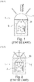
- a solar reactor 1 with direct heating Such a reactor 1 comprises a casing 2 delimiting the reaction chamber 3 in which the reagents of the endothermic reaction to be carried out are present.
- a transparent window 4 for concentrating solar radiation is mounted on top of the casing 2. This transparent window 4 therefore separates the reaction chamber 3 from the outside air and allows the solar flux to pass, which passes concentrated through the. dedicated opening 20 at the top of the chamber 2.
- this type of technology requires the use of a transparent window or porthole.
- the presence of this transparent surface can prove to be a handicap if the flows of reagents and products (gas, tank, tars) are poorly managed. Indeed, the soiling of this surface can cause its opacification and therefore its overheating under the effect of the concentrated flow. It is therefore necessary to keep this transparent window or porthole clean, which creates an operational difficulty.
- FIG. 2 We have schematically represented in figure 2 , a solar reactor 1 with indirect heating.
- an opaque wall 5 is fixed in the casing 2 and defines therewith the reaction chamber 3.
- the reaction chamber 3 is here delimited by a casing 2, the lower part 21 of which is a right cone and the upper part 22 is a blind right cylinder.
- the cone 21 is extended at its top downwards by an inlet 6 into which the gaseous reactants are injected.
- the blind cylinder 22 is for its part pierced with two bores 23, 24, one of which opens onto a tube 7 for injecting solid reagents and the other opens onto a tube 8 through which the reaction products are discharged.
- the jet of reactive gases is projected into the reaction chamber 3 and suspends the particles of the solid reactants injected through the tube 7.
- the heating is provided by the outside of the cone 21.
- This solar reactor 1 is shown in figure 4 : it uses the various components already explained with reference to the figure 3 , further with a body 9 consisting of a double casing in which is housed the casing 2 delimiting the reaction chamber 3, and on top by a transparent window 4 for concentrating the solar radiation which is held by a flange. There is also a part forming a cap 10 made of ceramic material which covers the top of the casing 2.
- this cap 10 limits the radiative losses towards the outside of the body cavity housing the casing 2 and delimits the opening 20, placed at the level of the focal point of the porthole 4, which allows the solar flux to enter in the direction of the heat transfer plate 5 which constitutes the bottom of the blind cylinder 22.
- Such a solar jet reactor has overall good performance for the targeted thermochemical conversion.
- the inventors have been able to observe that the indirect irradiation of solar radiation by the transfer plate 5 leads to strong temperature gradients in the plate and to significant associated thermal losses.
- poor heat transfer through the plate induces a strong temperature difference between the outer wall (the hottest) and the inner wall.
- the outer wall much hotter than the reaction medium, causes high radiative losses.
- the invention relates, in one of its aspects, to a solar reactor comprising a casing delimiting a reaction chamber, the casing comprising a lower part in the form of a right cone extended at its top by a inlet for injecting gaseous reagents and an upper part in the form of a straight blind cylinder, the cone and / or the side surface of the blind cylinder comprising two lateral bores, one of which is extended by a tube for injecting solid reagents and the other is extended by a tube of output of products resulting from the reaction, the bottom of the blind cylinder, the outer face of which is intended to receive solar radiation, having an inner face intended to be impacted by the jet of gaseous reactants.
- the internal face, impacted by the jet of gaseous reactants has a structured surface.
- the external face can also have a structured surface.
- An external fax machine with a structured surface maximizes the absorption of solar radiation. It is thus possible to textur the face or to deposit a selective treatment which maximizes the absorption of visible radiation and minimizes the emission in the infrared.
- the structured surface is a textured surface or a flat surface with one or more ribs and / or grooves.
- the solar reactor comprises a hollow cylinder, said confinement cylinder, arranged inside the casing with its lower end opening into the latter and its upper end closed by the internal face of the bottom of the cylinder. one-eyed.
- This confinement cylinder makes it possible to improve the hydrodynamics of the reactor by reducing the entrainment of particles, stabilizing the jet regime and increasing the residence time of the gas.
- the containment cylinder can be welded to the inner face of the bottom of the blind cylinder.
- the confinement cylinder can be supported by tabs in the extension of its lower end, fixed or resting against the cone of the envelope. Given the high temperatures reached on the bottom of the cylinder, such support for the confinement cylinder may be advantageous.
- the function of this propeller or these fins is to increase the exchange surface, to force the passage of gas over the entire volume of the reaction chamber and to form obstacles to the entrainment of particles. This makes it possible to improve both the heat exchanges and the residence time of the gases in the reactor and to reduce the entrainment of the particles. Care is taken that the fins are oriented in order to ensure that the potentially entrained particles can descend by gravity and thus avoid any accumulation zone.
- the solar reactor comprises a hollow cylinder, called the jet pipe cylinder, arranged inside the casing with its two ends opening into the latter, one of which is opposite the tube. injection of gaseous reagents.
- the confinement cylinder is arranged in the extension of the jet pipe cylinder.
- the bottom of the cylinder delimiting the reaction chamber is an attached plate and fixed inside the lateral surface of the cylinder.
- the cone and the lateral surface of the cylinder delimiting the reaction chamber are made of the same metal alloy resistant to high temperature, preferably an iron-chromium-aluminum alloy, while the bottom of the cylinder is made of silicon carbide (SiC). or graphite coated with SiC or tungsten.
- the reactor comprises an endless screw arranged in the injection tube for the solid reagents.
- a subject of the invention is also a method of operating a solar reactor intended for the thermochemical conversion of a carbonaceous feed, the reactor comprising a casing delimiting a reaction chamber, the casing comprising a lower part in the form of a 'a right cone extended at its top by an injection tube for gaseous reagents and an upper part in the form of a blind right cylinder, the cone and / or the lateral surface of the blind cylinder comprising two lateral bores, one of which is extended by an injection tube for solid reagents and the other is extended by an outlet tube for products resulting from the reaction, the bottom of the blind cylinder, the outer face of which is intended to receive solar radiation, a process according to which the temperature is adjusted. jet of gaseous reagents so that it impacts the internal face of the bottom of the blind cylinder.
- the impact of the jet of gaseous reactants is produced on a structured surface of the internal face.
- the invention therefore essentially consists in producing a solar jet reactor by dimensioning the reactor and adjusting the jet so that the latter impacts the transfer wall (impacting jet), formed by the bottom of the cylinder.
- the heat transfer face impacted by the jet is a structured wall.
- the wall is a structured wall.
- the jet is adjusted to impact the center of the plate, which makes it possible both to minimize the internal face-external face gradient of the bottom of the envelope cylinder but also the radial gradient since concentrating solar systems have peaks. flow at the center of the focal task zone where the jet will evacuate the maximum amount of calories.
- the surface structuring of the bottom of the cylinder improves the exchanges at the periphery of the jet [7].
- the term “structured surface” is understood to mean a non-planar surface, which can be textured or with protruding and / or recessed geometric reliefs (ribs, grooves).
- a structured surface transfer wall is a textured surface or a planar surface with one or more ribs and / or grooves. The textured surface exhibits roughness, whether the latter is regular or random.
- a subject of the invention is the use of the solar reactor described above for the gasification of a carbonaceous feedstock into reaction products, gasification reaction of a biomass, in particular a lignocellulosic biomass, or for a reforming reaction.
- the figures 1 to 5 relate to different examples of solar and jet reactors according to the state of the art. These figures 1 to 5 have already been commented on in the preamble and are therefore not commented on further below.
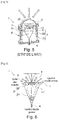
- FIG 5 a first example of a solar reactor 1 as it operates during the injection of the reactive gases and the solid reactants.
- This reactor 1 comprises a casing 2 delimits a reaction chamber 3 in which an endothermic chemical reaction, such as biomass gasification, must take place.
- the lower part 21 of the casing 2 is a right cone extended at its top by an inlet 6 for injecting gaseous reactants and the upper part 22 is a straight blind cylinder.
- a tube 7 for injecting solid reagents also opens into the reaction chamber 3 as well as a tube 8 through which the products resulting from the reaction are evacuated.
- the bottom 5 of the blind cylinder constitutes the heat transfer wall on which the concentrated solar radiation is focused according to a Gaussian symbolized on this figure 6 .
- the internal face that is to say that facing the combustion chamber 3 has a structured surface and the jet of gaseous reactants is adjusted so that it impacts this structured surface.
- the whole of the casing 2 except the bottom is made of an Fe-Cr-Al alloy while the bottom 5 is made of silicon carbide (SiC).
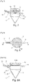
- the figures 7 to 8A illustrate an alternative embodiment according to which the bottom 5 is an attached plate and fixed inside the cylinder 22 and which comprises ribs 50 centered on the center of the cylinder and concentric.
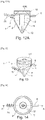
- FIGS. 9 to 10A illustrate an embodiment according to which a hollow confinement cylinder 11 is arranged inside the casing 2 with its lower end opening into the latter and its upper end welded to the ribbed plate 5 50.
- This confinement cylinder 11 is supported by tabs 110 in the extension of its lower end, fixed or resting against the cone 21 of the casing.
- This confinement cylinder 11 makes it possible to improve the hydrodynamics of the reactor, by reducing the entrainment of the particles and by stabilizing the injected jet regime.
- the figures 11 to 12A illustrate an embodiment according to which a hollow jet pipe cylinder 12 is arranged inside the casing 2 with its two ends opening into it.
- the confinement cylinder 11 is arranged in the extension of the jet pipe cylinder 12 which is opposite the tube 6 for injecting the gaseous reactants.
- This hollow cylinder 12 also makes it possible to improve the hydrodynamics by channeling the jet at the base of the cone 21.
- the figures 13 to 14A illustrate an alternative embodiment according to which a propeller 13 is wound and fixed around the confinement cylinder 11 inside the reaction chamber 3.
- This propeller 13 makes it possible to increase the heat exchange surface within the chamber of reaction 3 and also to increase the residence time of the gases in the chamber 3 and to reduce the entrainment of the particles of the solid reactants.
- the figures 15 to 16A illustrate an alternative embodiment according to which, instead of the propeller, fins 15 are fixed along and around the confinement cylinder 11.
- the tube 7 for injecting the solid particles and the tube 8 for the outlet of the products resulting from the reaction are diametrically opposed.
- a worm 70 housed in the injection tube 7 facilitates the injection of the particles.
- the particle injection tube 7 passes through the side wall of the cylinder 22, while in the variants of figures 13 to 14A , 15 to 16A , it crosses cone 21.
- the heat transfer plate has a ribbed structure in concentric circles.
- any other surface treatment can be considered which makes it possible to improve the quality of transfers at the level of the impacting jet: it can be other types, shapes and arrangement of ribs, grooves, texturing surface, of controlled roughness, micro-structuring or other.
Landscapes
- Engineering & Computer Science (AREA)
- Chemical & Material Sciences (AREA)
- Organic Chemistry (AREA)
- Environmental & Geological Engineering (AREA)
- Mechanical Engineering (AREA)
- General Engineering & Computer Science (AREA)
- Combustion & Propulsion (AREA)
- Oil, Petroleum & Natural Gas (AREA)
- Sustainable Energy (AREA)
- Toxicology (AREA)
- Life Sciences & Earth Sciences (AREA)
- Physics & Mathematics (AREA)
- Electromagnetism (AREA)
- Health & Medical Sciences (AREA)
- General Health & Medical Sciences (AREA)
- Sustainable Development (AREA)
- Chemical Kinetics & Catalysis (AREA)
- Devices And Processes Conducted In The Presence Of Fluids And Solid Particles (AREA)
- Processing Of Solid Wastes (AREA)
- Production Of Liquid Hydrocarbon Mixture For Refining Petroleum (AREA)
- Organic Low-Molecular-Weight Compounds And Preparation Thereof (AREA)
- Physical Or Chemical Processes And Apparatus (AREA)
Abstract
Description
- La présente invention concerne le domaine des réacteurs dit « solaires », c'est-à-dire utilisant au moins en partie l'énergie du rayonnement solaire qui est concentrée en tant qu'apport de l'énergie nécessaire à une réaction chimique endothermique.
- Plus particulièrement, l'invention a trait à une amélioration d'un type de réacteur solaire, à jet, en vue d'augmenter les échanges thermiques entre l'énergie solaire concentrée qui est apportée et le jet.
- L'application principale visée par un réacteur solaire selon l'invention est la conversion thermochimique d'une charge carbonée, en particulier un hydrocarbure ou une biomasse, en un gaz de synthèse contenant majoritairement de l'hydrogène (H2) et du monoxyde de carbone (CO), en vue de produire des carburants liquides (Diesel Fischer-Tropsch "FT", Diméthyl éther "DME", Méthanol) ou gazeux (gaz naturel synthétique, "SNG" ou "Synthetic Natural Gas" en anglais) ou autres produits chimiques de synthèse, tels que le méthanol par exemple ou bien en hydrocarbures insaturées et/ou aromatiques tels que des produits issus du vapocraquage des coupes pétrolières légères.
- On désigne sous l'appellation « charge carbonée », tout matériau combustible constitué de composés contenant du carbone.
- Il peut donc s'agir de biomasse, c'est-à-dire tout matériau inhomogène d'origine végétale contenant du carbone, tel que de la biomasse ligno-cellulosique, des résidus forestiers ou agricoles (paille), qui peut être quasi-sec ou imbibé d'eau comme les déchets ménagers.
- Il peut aussi s'agir d'un hydrocarbure, en particulier un combustible d'origine fossile, tel que le charbon.
- Il peut aussi s'agir de déchets combustibles d'origine industrielle contenant du carbone, tel que des matières plastiques ou des pneumatiques.
- II peut aussi s'agir d'une combinaison de biomasse et de combustible d'origine fossile. D'autres applications peuvent être envisagées. Par exemple, le reformage peut être mis en œuvre avantageusement par un réacteur solaire selon l'invention.
- De manière générale, toute réaction chimique endothermique peut être mise en œuvre par l'invention.
- Les réacteurs dits « solaires » sont des réacteurs chimiques adaptés pour convertir au moins en partie l'énergie du rayonnement solaire concentré en de la chaleur afin de mettre en œuvre des réactions endothermiques de type reformage, gazéification, décarbonatation, craquage... De l'art antérieur, on connaît bon nombre de conceptions de réacteurs solaires adaptés à plusieurs réactions chimiques ou de manière privilégiée pour un type de réaction. On peut citer ici la publication [1], qui fait une revue générale des conceptions de tous les réacteurs solaires connus, ou encore la publication [2] qui se focalise sur les réacteurs solaires adaptés particulièrement au reformage ou encore la publication [3] qui détaille ceux pour la gazéification.
- De manière générale, il existe trois types de réacteurs solaires : ceux à lits fluidisés, ceux à lits fixes et ceux à flux entraînés.
- Indépendamment du type de réacteur, on distingue deux grandes familles de réacteurs à savoir les réacteurs à chauffage par ensoleillement direct et les réacteurs à chauffage par ensoleillement indirect. La distinction se fait sur la façon dont les réactifs vont recevoir le flux solaire. Dans le cas d'un ensoleillement direct, les réactifs sont directement exposés au flux solaire concentré, ce qui permet d'atteindre de hauts niveaux de température, en fonction du facteur de concentration.
- On a représenté schématiquement en
figure 1 , un réacteur solaire 1 à chauffage direct. Un tel réacteur 1 comprend une enveloppe 2 délimitant la chambre de réaction 3 dans laquelle sont présents les réactifs de la réaction endothermique à réaliser. Un hublot transparent 4 de concentration du rayonnement solaire est monté sur le dessus de l'enveloppe 2. Ce hublot transparent 4 sépare donc la chambre de réaction 3 de l'air extérieur et laisse passer le flux solaire, qui passe concentré à travers l'ouverture 20 dédiée en haut de la chambre 2. Cependant, ce type de technologie nécessite l'utilisation d'une fenêtre ou d'un hublot transparent. La présence de cette surface transparente peut s'avérer handicapante si les flux de réactifs et de produits (gaz, char, goudrons) sont mal gérés. En effet, la salissure de cette surface peut entraîner son opacification et donc sa surchauffe sous l'effet du flux concentré. Il s'avère donc nécessaire de maintenir propre cette fenêtre ou hublot transparent, ce qui crée une difficulté opérationnelle - A l'inverse, dans le cas d'un ensoleillement indirect, c'est une paroi opaque qui reçoit le flux solaire concentré et le transmet par rayonnement infrarouge aux réactifs à l'intérieur du réacteur ce qui évite tout problème lié à la présence d'un hublot. En revanche, l'utilisation d'une paroi de transfert induit de plus fortes pertes thermiques dans le réacteur du fait de la réémission d'une partie du rayonnement absorbé vers l'extérieur. Certaines technologies de réacteur solaire pour la gazéification de biomasse permettent la conception de réacteur fonctionnant en mode de chauffage direct ou indirect mais pour d'autres seul un type d'ensoleillement est possible.
- On a représenté schématiquement en
figure 2 , un réacteur solaire 1 à chauffage indirect. Ici, une paroi opaque 5 est fixée dans l'enveloppe 2 et délimite avec celle-ci la chambre de réaction 3. - Les réacteurs dits à jet sont développés depuis des décennies pour des procédés qui impliquent des gaz et des particules solides, notamment pour le séchage de céréales. Ses caractéristiques sont intéressantes en termes d'hydrodynamique. On pourra se reporter à la publication [4]. Les chambres de réaction des réacteurs sont conventionnellement chauffées soit par le gaz de jet en lui-même, qui est préalablement chauffé, soit par combustion interne, soit par chauffage externe.
- On a représenté en
figure 3 , un exemple de réacteur à jet l' à chauffage externe. La chambre de réaction 3 est ici délimitée par une enveloppe 2 dont la partie inférieure 21 est un cône droit et la partie supérieure 22 est un cylindre droit borgne. Le cône 21 est prolongé à son sommet vers le bas par une entrée 6 dans laquelle sont injectés les réactifs gazeux. Le cylindre borgne 22 est quant à lui percé de deux perçages 23, 24 dont l'un débouche sur un tube 7 d'injection des réactifs solides et l'autre débouche sur un tube 8 par lequel les produits de la réaction sont évacués. Comme symbolisé par les flèches blanches, le jet de gaz réactifs est projeté dans la chambre de réaction 3 et met en suspension les particules des réactifs solides injectées par le tube 7. Comme illustré sur cettefigure 3 , le chauffage est apporté par l'extérieur du cône 21. - Dans le cadre des travaux de thèse [5], un nouveau type de réacteur solaire a été mis au point : il reprend le principe de fonctionnement d'un réacteur à jet avec, en lieu et place d'un chauffage externe sur l'enveloppe, un apport de chaleur qui est fait par le rayonnement solaire concentré vers le fond borgne 5 du cylindre de l'enveloppe 2. Ce réacteur à jet solaire 1 destiné à la gazéification de biomasse répond aux contraintes des autres types de réacteurs avec de relativement bons transferts de chaleur et de matières, une fluidisation des particules robuste et des temps de séjours importants au moins pour la partie solide.
- La demanderesse a également déjà conçu et réalisé un réacteur à jet solaire à mode de chauffage indirect. Ce réacteur solaire 1 est montré en
figure 4 : il reprend les différents composants déjà explicités en référence avec lafigure 3 , avec en outre un corps 9 constitué par une double enveloppe dans laquelle est logée l'enveloppe 2 délimitant la chambre de réaction 3, et sur le dessus par un hublot transparent 4 de concentration du rayonnement solaire qui est maintenu par bride. On distingue également une pièce formant un chapeau 10 en matériau céramique qui vient coiffer le dessus de l'enveloppe 2. Comme symbolisé, ce chapeau 10 limite les pertes radiatives vers l'extérieur de la cavité du corps logeant l'enveloppe 2 et délimite l'ouverture 20, placée au niveau du point focal du hublot 4, qui laisse entrer le flux solaire en direction de la plaque de transfert de chaleur 5 qui constitue le fond du cylindre borgne 22. - Un tel réacteur à jet solaire présente globalement de bonnes performances pour la conversion thermochimique visée.
- Toutefois, les inventeurs ont pu constater que l'irradiation indirecte du rayonnement solaire par la plaque de transfert 5 conduit à de forts gradients de température dans la plaque et à des pertes thermiques associées importantes. Or, un mauvais transfert de chaleur à travers la plaque induit une forte différence de température entre la paroi externe (la plus chaude) et la paroi interne. La paroi externe, bien plus chaude que le milieu réactionnel, entraine de fortes pertes radiatives.
- Par ailleurs, il est connu que les jets de fluide impactant une plaque améliorent le coefficient d'échange thermique entre ladite plaque et le fluide impactant [6].
- Il existe donc un besoin pour améliorer les réacteurs à jet solaire notamment afin de maximiser les transferts thermiques au niveau de la paroi de transfert de chaleur qui reçoit le rayonnement solaire concentré et doit en restituer la chaleur à la chambre du réacteur. Le but de l'invention est de répondre au moins en partie à ce besoin.
- Pour ce faire, l'invention concerne, sous l'un de ses aspects, un réacteur solaire comprenant une enveloppe délimitant une chambre de réaction, l'enveloppe comprenant une partie inférieure sous la forme d'un cône droit prolongé à son sommet par une entrée d'injection de réactifs gazeux et une partie supérieure sous la forme d'un cylindre droit borgne, le cône et/ou la surface latérale du cylindre borgne comprenant deux perçages latéraux dont un est prolongé par un tube d'injection de réactifs solides et l'autre est prolongé par un tube de sortie de produits issus de la réaction, le fond du cylindre borgne dont la face externe est destinée à recevoir le rayonnement solaire présentant une face interne destinée à être impactée par le jet de réactifs gazeux.
- Selon un mode de réalisation avantageux, la face interne, impactée par le jet de réactifs gazeux, a une surface structurée.
- Avantageusement, la face externe peut également avoir une surface structurée. Une faxe externe avec une surface structurée permet de maximiser l'absorption du rayonnement solaire. On peut ainsi réaliser une texturation de la face ou un dépôt d'un traitement sélectif qui maximise l'absorption du rayonnement visible et minimise l'émission dans l'infra-rouge. De préférence, la surfacs structurée est une surface texturée ou une surface plane à une ou plusieurs nervures et/ou rainures
- Selon un premier mode de réalisation, le réacteur solaire comprend un cylindre creux, dit cylindre de confinement, agencé à l'intérieur de l'enveloppe avec son extrémité inférieure débouchant dans cette dernière et son extrémité supérieure fermée par la face interne du fond du cylindre borgne. Ce cylindre de confinement permet d'améliorer l'hydrodynamique du réacteur par une diminution de l'entrainement des particules, une stabilisation du régime de jet et une augmentation du temps de séjour du gaz.
- Le cylindre de confinement peut être soudé sur la face interne du fond du cylindre borgne. Avantageusement, le cylindre de confinement peut être supporté par des pattes dans le prolongement de son extrémité inférieure, fixées ou en appui contre le cône de l'enveloppe. Compte tenu des hautes températures atteintes sur le fond du cylindre, un tel supportage du cylindre de confinement peut être avantageux.
- Selon une variante de réalisation, on peut prévoir une hélice enroulée et fixée autour du cylindre de confinement ou des ailettes fixées le long et autour du cylindre de confinement à l'intérieur de la chambre de réaction. Cette hélice ou ces ailettes ont pour fonction d'augmenter la surface d'échange, de forcer le passage du gaz sur tout le volume de la chambre de réaction et de former des obstacles à l'entraînement de particules. Cela permet d'améliorer à la fois les échanges thermiques, le temps de séjour des gaz dans le réacteur et de diminuer l'entraînement des particules. On veille à ce que les ailettes soient orientées afin d'assurer que les particules potentiellement entraînées puissent redescendre par gravité et ainsi éviter toute zone d'accumulation.
- Selon un deuxième mode de réalisation, le réacteur solaire comprend un cylindre creux, dit cylindre de canalisation de jet, agencé à l'intérieur de l'enveloppe avec ses deux extrémités débouchant dans celle-ci, dont une est en regard du tube d'injection des réactifs gazeux. Selon une configuration particulièrement avantageuse, le cylindre de confinement est agencé dans le prolongement du cylindre de canalisation de jet.
- Selon une variante de réalisation avantageuse, le fond du cylindre délimitant la chambre de réaction est une plaque rapportée et fixée à l'intérieur de la surface latérale du cylindre.
- De préférence, le cône et la surface latérale du cylindre délimitant la chambre de réaction sont en un même alliage métallique résistant à haute température, de préférence un alliage fer-chrome-aluminium tandis que le fond du cylindre est en carbure de silicium (SiC) ou en graphite revêtu de SiC ou en tungstène.
- Selon un mode de réalisation, le réacteur comprend une vis sans fin agencée dans le tube d'injection des réactifs solides.
- L'invention a également pour objet, un procédé de fonctionnement d'un réacteur solaire destiné à la conversion thermochimique d'une charge carbonée, le réacteur comprenant une enveloppe délimitant une chambre de réaction, l'enveloppe comprenant une partie inférieure sous la forme d'un cône droit prolongé à son sommet par un tube d'injection de réactifs gazeux et une partie supérieure sous la forme d'un cylindre droit borgne, le cône et/ou la surface latérale du cylindre borgne comprenant deux perçages latéraux dont un est prolongé par un tube d'injection de réactifs solides et l'autre est prolongé par un tube de sortie de produits issus de la réaction, le fond du cylindre borgne dont la face externe est destinée à recevoir le rayonnement solaire, procédé selon lequel on règle le jet de réactifs gazeux de sorte qu'il vienne impacter la face interne du fond du cylindre borgne.
- Selon un mode de réalisation avantageux, l'impact du jet de réactifs gazeux est réalisé sur une surface structurée de la face interne.
- L'invention consiste donc essentiellement à réaliser un réacteur à jet solaire en dimensionnant le réacteur et réglant le jet de sorte que ce dernier impacte la paroi de transfert (jet impactant), formée par le fond du cylindre.
- Avantageusement, la face de transfert de chaleur impactée par le jet est une paroi structurée. Ainsi, de meilleurs coefficients d'échanges thermiques seront obtenus en paroi grâce à cette combinaison judicieuse des propriétés des écoulements de jets impactant, qui permettent d'obtenir de très bons transferts de chaleur, et le réacteur à jet qui permet un écoulement de jet et avec sa paroi structurée également une amélioration des transferts de chaleur.
- Le jet est réglé pour venir impacter le centre de la plaque, ce qui permet à la fois de minimiser le gradient face interne-face externe du fond du cylindre de l'enveloppe mais aussi le gradient radial puisque les systèmes solaires à concentration présentent des pics de flux au centre de la tâche focale zone où le jet va évacuer le maximum de calories. La structuration de surface du fond du cylindre permet d'améliorer les échanges en périphérie du jet [7]. Par « surface structurée », on entend dans le cadre de l'invention, une surface non plane, qui peut être texturée ou avec des reliefs géométriques en saillie et/ou en retrait (nervures, rainures). Ainsi, une paroi de transfert à la surface structurée est une surface texturée ou une surface plane à une ou plusieurs nervures et/ou rainures. La surface texturée présente une rugosité, que cette dernière soit régulière ou aléatoire.
- L'invention a enfin pour objet l'utilisation du réacteur solaire décrit précédemment pour la gazéification d'une charge carbonée en produits de réaction, réaction de gazéification d'une biomasse, notamment une biomasse ligno-cellulosique, ou pour une réaction de reformage. D'autres avantages et caractéristiques de l'invention ressortiront mieux à la lecture de la description détaillée d'exemples de mise en œuvre de l'invention faite à titre illustratif et non limitatif en référence aux figures suivantes.
-
- [
Fig 1 ] est une vue schématique en coupe longitudinale d'un réacteur solaire selon l'état de l'art à mode de chauffage direct. - [
Fig 2 ] est une vue schématique en coupe longitudinale d'un réacteur solaire selon l'état de l'art à mode de chauffage indirect. - [
Fig 3 ] est une vue schématique en coupe longitudinale d'un réacteur à jet selon l'état de l'art à chauffage externe. - [
Fig 4 ] est une vue schématique en coupe longitudinale d'un réacteur solaire à jet selon l'état de l'art à apport de chaleur par rayonnement solaire. - [
Fig 5 ] est une vue schématique en coupe longitudinale d'un autre réacteur solaire à jet selon l'état de l'art à apport de chaleur par rayonnement solaire. - [
Fig 6 ] est une vue schématique en coupe longitudinale d'un réacteur solaire à jet selon l'invention. - [
Fig 7 ] est une vue en perspective d'un exemple de réacteur solaire à jet selon l'invention. - [
Fig 8 ] est une vue de dessus du réacteur selon lafigure 7 . - [
Fig 8A ] est une vue en coupe longitudinale selon A-A du réacteur selon lesfigures 7 et 8 . - [
Fig 9 ] est une vue en perspective d'un mode de réalisation avantageux de réacteur solaire à jet selon l'invention, intégrant un cylindre de confinement à l'intérieur de la chambre de réaction. - [
Fig 10 ] est une vue de dessus du réacteur selon lafigure 9 . - [
Fig 10A ] est une vue en coupe longitudinale selon A-A du réacteur selon lesfigures 9 et 10 . - [
Fig 11 ] est une vue en perspective d'un autre mode de réalisation avantageux de réacteur solaire à jet selon l'invention, intégrant un cylindre de canalisation du jet en sus du cylindre de confinement à l'intérieur de la chambre de réaction. - [
Fig 12 ] est une vue de dessus du réacteur selon lafigure 11 . - [
Fig 12A ] est une vue en coupe longitudinale selon A-A du réacteur selon lesfigures 11 et 12 . - [
Fig 13 ] est une vue en perspective d'une variante de réalisation avantageuse de réacteur solaire à jet selon l'invention, intégrant une hélice d'échange thermique autour du cylindre de confinement à l'intérieur de la chambre de réaction. - [
Fig 14 ] est une vue de dessus du réacteur selon lafigure 13 . - [
Fig 14A ] est une vue en coupe longitudinale selon A-A du réacteur selon lesfigures 13 et 14 . - [
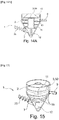
Fig 15 ] est une vue en perspective d'une autre variante de réalisation avantageuse de réacteur solaire à jet selon l'invention, intégrant des ailettes d'échange autour du cylindre de confinement à l'intérieur de la chambre de réaction. - [
Fig 16 ] est une vue de dessus du réacteur selon lafigure 15 . - [
Fig 16A ] est une vue en coupe longitudinale selon A-A du réacteur selon lesfigures 15 et16 . - Les
figures 1 à 5 sont relatives à des exemples différents des réacteurs solaires et à jet selon l'état de l'art. Cesfigures 1 à 5 ont déjà été commentées en préambule et ne le sont donc pas plus ci-après. - Par souci de clarté, les mêmes références désignant les mêmes éléments selon l'état de l'art et selon l'invention sont utilisées pour toutes les
figures 1 à 16A . - Dans l'ensemble de la présente demande, les termes « inférieur », « supérieur », « bas », « haut », « dessous » et « dessus » sont à comprendre par référence par rapport à un réacteur à jet solaire agencé avec son axe longitudinal à la verticale.
- On a représenté en
figure 5 , un premier exemple de réacteur solaire 1 tel qu'il fonctionne lors de l'injection des gaz réactifs et des réactifs solides. - Ce réacteur 1 comprend une enveloppe 2 délimite une chambre de réaction 3 dans laquelle une réaction chimique endothermique, telle qu'une gazéification de biomasse, doit avoir lieu.
- La partie inférieure 21 de l'enveloppe 2 est un cône droit prolongé à son sommet par une entrée 6 d'injection de réactifs gazeux et la partie supérieure 22 est un cylindre droit borgne. Un tube 7 d'injection de réactifs solides débouche également dans la chambre de réaction 3 ainsi qu'un tube 8 par lequel les produits issus de la réaction sont évacués.
- Le fond 5 du cylindre borgne constitue la paroi de transfert thermique sur laquelle le rayonnement solaire concentré est focalisé selon une gaussienne symbolisée sur cette
figure 6 . - Selon l'invention, la face interne, c'est-à-dire celle tournée vers la chambre de combustion 3 présente une surface structurée et le jet de réactifs gazeux est réglé de sorte qu'il vienne impacter cette surface structurée.
- L'ensemble de l'enveloppe 2 à l'exception du fond est en un alliage Fe-Cr-Al tandis que le fond 5 est en carbure de silicium (SiC).
- Les
figures 7 à 8A illustrent une variante de réalisation selon laquelle le fond 5 est une plaque rapportée et fixée à l'intérieur du cylindre 22 et qui comprend des nervures 50 centrées sur le centre du cylindre et concentriques. - Les
figures 9 à 10A illustrent un mode de réalisation selon lequel un cylindre creux de confinement 11 est agencé à l'intérieur de l'enveloppe 2 avec son extrémité inférieure débouchant dans cette dernière et son extrémité supérieure soudée sur la plaque 5 à nervures 50. Ce cylindre de confinement 11 est supporté par des pattes 110 dans le prolongement de son extrémité inférieure, fixées ou en appui contre le cône 21 de l'enveloppe. Ce cylindre de confinement 11 permet d'améliorer l'hydrodynamique du réacteur, en diminuant l'entrainement des particules et en stabilisant le régime de jet injecté. - Les
figures 11 à 12A illustrent un mode de réalisation selon lequel un cylindre creux de canalisation de jet 12 est agencé à l'intérieur de l'enveloppe 2 avec ses deux extrémités débouchant dans celle-ci. Le cylindre de confinement 11 est agencé dans le prolongement du cylindre de canalisation de jet 12 qui est en regard du tube 6 d'injection des réactifs gazeux. Ce cylindre creux 12 permet également d'améliorer l'hydrodynamique en canalisant le jet à la base du cône 21. - Les
figures 13 à 14A illustrent une variante de réalisation selon laquelle une hélice 13 est enroulée et fixée autour du cylindre de confinement 11 à l'intérieur de la chambre de réaction 3. Cette hélice 13 permet d'augmenter la surface d'échange thermique au sein de la chambre de réaction 3 et également d'augmenter le temps de séjour des gaz dans la chambre 3 et de diminuer l'entraînement des particules des réactifs solides. - Les
figures 15 à 16A illustrent une variante de réalisation selon laquelle, en lieu et place de l'hélice, des ailettes 15 sont fixées le long et autour du cylindre de confinement 11. - Dans l'ensemble des variantes illustrées, le tube 7 d'injection des particules solides et le tube 8 de sortie des produits issus de la réaction sont diamétralement opposés. Une vis sans fin 70 logée dans le tube d'injection 7 facilite l'injection des particules.
- Dans les variantes des
figures 7 à 8A ,9 à 10A ,11 à 12A , le tube 7 d'injection des particules traverse la paroi latérale du cylindre 22, tandis que dans les variantes desfigures 13 à 14A ,15 à 16A , il traverse le cône 21. - L'invention n'est pas limitée aux exemples qui viennent d'être décrits ; on peut notamment combiner entre elles des caractéristiques des exemples illustrés au sein de variantes non illustrées.
- D'autres variantes et améliorations peuvent être envisagées sans pour autant sortir du cadre de l'invention.
- Dans les exemples illustrés, la plaque de transfert de chaleur présente une structure nervurée en cercles concentriques. Pour la structuration de surface, on peut envisager tout autre traitement de surface qui permet d'améliorer la qualité des transferts au niveau du jet impactant : il peut s'agir d'autres types, formes et agencement de nervures, de rainures, une texturation de surface, d'une rugosité contrôlée, une micro structuration ou autre.
-
- [1]: Steinfeld, R. Palumbo, « Solar thermochemicalprocess technology », Encyclopedia of physical science & technologie, R. A. Meyers Ed., Academic Press, 15, 237-256, 2001.
- [2]:C. Agrafiotis, H.v. Storch, M. Roeb, C. Sattler, « Solar thermal reforming of methane feedstocks for hydrogen and syngas production »-A review, Renewable and Sustainable Energy Reviews, 29, 2014, 656-682.
- [3]: M. Puig-Arnavat, E.A. Tora, J.C. Bruno, A. Coronas, « State of the art on reactors design for solar gasification of carbonaceous feedstock », Solar Energy, 97, 2013, 67-84.
- [4]: Lopez, G., Cortazar, M., Alvarez, J., Amutio, M., Bilbao, J., & Olazar, M. (2017). "Assessment of a conical spouted with an enhanced fountain bed for biomass gasification." Fuel, 203, 825-831.
- [5] : Bellouard Q., « Valorisation de biomasse en vecteur énergétique par voie thermochimique solaire », thèse, 2016.
- [6] : Yokomine, T., Shimizu, A., Saitoh, A., & Higa, K. (2002). "Heat transfer of multiple impinging jets with gas-solid suspensions." Experimental thermal and fluid science, 26 (6-7), 617-626.
- [7] : Kito, M., Takezaki, M., Shakouchi, T., Tsujimoto, K., & Ando, T. (2012). "Enhancement of impingement heat transfer on a flat plate with ribs. " World Academy of Science, Engineering and Technology, 6, 1367-1373.
Claims (15)
- Réacteur solaire (1) comprenant une enveloppe (2) délimitant une chambre de réaction (3), l'enveloppe comprenant une partie inférieure (21) sous la forme d'un cône droit prolongé à son sommet par une entrée d'injection (6) de réactifs gazeux et une partie supérieure (22) sous la forme d'un cylindre droit borgne (22), le cône et/ou la surface latérale du cylindre borgne comprenant deux perçages latéraux dont un est prolongé par un tube (7) d'injection de réactifs solides et l'autre est prolongé par un tube (8) de sortie de produits issus de la réaction, le fond (5) du cylindre borgne, dont la face externe est destinée à recevoir le rayonnement solaire, présentant une face interne destinée à être impactée par le jet de réactifs gazeux, la face interne ayant une surface structurée.
- Réacteur solaire (1) selon la revendication 1 , la face externe ayant une surface structurée.
- Réacteur solaire (1) selon la revendication 1 ou 2, la surface structurée de la face interne et/ou la surface structurée de la face externe étant une surface texturée ou une surface plane à une ou plusieurs nervures et/ou rainures.
- Réacteur solaire (1) selon l'une des revendications précédentes, comprenant un cylindre creux, dit cylindre de confinement (11), agencé à l'intérieur de l'enveloppe avec son extrémité inférieure débouchant dans cette dernière et son extrémité supérieure fermée par la face interne du fond du cylindre borgne.
- Réacteur solaire (1) selon la revendication 4, le cylindre de confinement étant soudé sur la face interne du fond du cylindre borgne.
- Réacteur solaire (1) selon la revendication 4 ou 5, le cylindre de confinement étant supporté par des pattes dans le prolongement de son extrémité inférieure, fixées ou en appui contre le cône de l'enveloppe.
- Réacteur solaire (1) selon l'une des revendications 4 à 6, comprenant une hélice (13) enroulée et fixée autour du cylindre de confinement ou des ailettes (15) fixées le long et autour du cylindre de confinement à l'intérieur de la chambre de réaction.
- Réacteur solaire (1) selon l'une des revendications précédentes, comprenant un cylindre creux, dit cylindre de canalisation de jet (12), agencé à l'intérieur de l'enveloppe avec ses deux extrémités débouchant dans celle-ci, dont une est en regard du tube d'injection des réactifs gazeux.
- Réacteur solaire (1) selon la revendication 8 en combinaison avec l'une des revendications 5 à 8, le cylindre de confinement étant agencé dans le prolongement du cylindre de canalisation de jet.
- Réacteur solaire (1) selon l'une des revendications précédentes, le fond du cylindre borgne délimitant la chambre de réaction étant une plaque rapportée et fixée à l'intérieur de la surface latérale du cylindre.
- Réacteur solaire (1) selon l'une des revendications précédentes, le cône et la surface latérale du cylindre délimitant la chambre de réaction étant en un même alliage métallique résistant à haute température, de préférence un alliage fer-chrome-aluminium tandis que le fond du cylindre est en carbure de silicium (SiC) ou en graphite revêtu de SiC ou en tungstène.
- Réacteur solaire (1) selon l'une des revendications précédentes, comprenant une vis sans fin agencée dans le tube d'injection des réactifs solides.
- Procédé de fonctionnement d'un réacteur solaire (1) destiné à la conversion thermochimique d'une charge carbonée, le réacteur comprenant une enveloppe (2) délimitant une chambre de réaction, l'enveloppe comprenant une partie inférieure (21) sous la forme d'un cône droit prolongé à son sommet par un tube d'injection de réactifs gazeux et une partie supérieure (22) sous la forme d'un cylindre droit borgne, le cône et/ou la surface latérale du cylindre borgne comprenant deux perçages latéraux dont un est prolongé par un tube d'injection de réactifs solides et l'autre est prolongé par un tube de sortie de produits issus de la réaction, le fond du cylindre borgne dont la face externe est destinée à recevoir le rayonnement solaire, procédé selon lequel on règle le jet de réactifs gazeux de sorte qu'il vienne impacter la face interne du fond du cylindre borgne.
- Procédé de fonctionnement selon la revendication 13, l'impact du jet de réactifs gazeux étant réalisé sur une surface structurée de la face interne.
- Utilisation du réacteur solaire (1) selon l'une des revendications 1 à 12 pour la gazéification d'une charge carbonée en produits de réaction, réaction de gazéification d'une biomasse, notamment une biomasse ligno-cellulosique, ou pour une réaction de reformage.
Priority Applications (1)
| Application Number | Priority Date | Filing Date | Title |
|---|---|---|---|
| HRP20240754TT HRP20240754T1 (hr) | 2019-11-14 | 2020-11-12 | Mlazni solarni reaktor s poboljšanim prijenosom topline i postupak rada mlaznog solarnog reaktora s poboljšanim prijenosom topline |
Applications Claiming Priority (1)
| Application Number | Priority Date | Filing Date | Title |
|---|---|---|---|
| FR1912693A FR3103259B1 (fr) | 2019-11-14 | 2019-11-14 | Réacteur solaire à jet à transfert thermique amélioré. Procédé de fonctionnement associé, application à la gazéification de biomasse ou au reformage. |
Publications (3)
| Publication Number | Publication Date |
|---|---|
| EP3822540A2 true EP3822540A2 (fr) | 2021-05-19 |
| EP3822540A3 EP3822540A3 (fr) | 2021-07-14 |
| EP3822540B1 EP3822540B1 (fr) | 2024-03-20 |
Family
ID=69572169
Family Applications (1)
| Application Number | Title | Priority Date | Filing Date |
|---|---|---|---|
| EP20207314.4A Active EP3822540B1 (fr) | 2019-11-14 | 2020-11-12 | Réacteur solaire à jet à transfert thermique amélioré et procédé de fonctionnement d'un réacteur solaire à jet à transfert thermique amélioré |
Country Status (5)
| Country | Link |
|---|---|
| EP (1) | EP3822540B1 (fr) |
| ES (1) | ES2980823T3 (fr) |
| FR (1) | FR3103259B1 (fr) |
| HR (1) | HRP20240754T1 (fr) |
| PT (1) | PT3822540T (fr) |
Cited By (1)
| Publication number | Priority date | Publication date | Assignee | Title |
|---|---|---|---|---|
| CN115093882A (zh) * | 2022-06-20 | 2022-09-23 | 中国石油大学(华东) | 多用途太阳能热化学反应测试系统 |
Family Cites Families (2)
| Publication number | Priority date | Publication date | Assignee | Title |
|---|---|---|---|---|
| US7449158B2 (en) * | 2003-10-01 | 2008-11-11 | Intevep, S.A. | Apparatus and gasification of carbonaceous solid materials |
| WO2015048845A1 (fr) * | 2013-10-02 | 2015-04-09 | Adelaide Research & Innovation Pty Ltd | Système hybride solaire et à combustion en boucle chimique |
-
2019
- 2019-11-14 FR FR1912693A patent/FR3103259B1/fr active Active
-
2020
- 2020-11-12 HR HRP20240754TT patent/HRP20240754T1/hr unknown
- 2020-11-12 PT PT202073144T patent/PT3822540T/pt unknown
- 2020-11-12 ES ES20207314T patent/ES2980823T3/es active Active
- 2020-11-12 EP EP20207314.4A patent/EP3822540B1/fr active Active
Non-Patent Citations (7)
| Title |
|---|
| BELLOUARD Q.: "Valorisation de biomasse en vecteur énergétique par voie thermochimique solaire", 2016 |
| C. AGRAFIOTISH.V. STORCHM. ROEBC. SATTLER: "Solar thermal reforming of methane feedstocks for hydrogen and syngas production", A REVIEW, RENEWABLE AND SUSTAINABLE ENERGY REVIEWS, vol. 29, 2014, pages 656 - 682, XP055256195, DOI: 10.1016/j.rser.2013.08.050 |
| KITO, M.TAKEZAKI, M.SHAKOUCHI, T.TSUJIMOTO, K.ANDO, T.: "Enhancement of impingement heat transfer on a flat plate with ribs", WORLD ACADEMY OF SCIENCE, ENGINEERING AND TECHNOLOGY, vol. 6, 2012, pages 1367 - 1373 |
| LOPEZ, G.CORTAZAR, M.ALVAREZ, J.AMUTIO, M.BILBAO, J.OLAZAR, M.: "Assessment of a conical spouted with an enhanced fountain bed for biomass gasification", FUEL, vol. 203, 2017, pages 825 - 831, XP085046235, DOI: 10.1016/j.fuel.2017.05.014 |
| M. PUIG-ARNAVATE.A. TORAJ.C. BRUNOA. CORONAS: "State of the art on reactors design for solar gasification of carbonaceous feedstock", SOLAR ENERGY, vol. 97, 2013, pages 67 - 84 |
| STEINFELD, R. PALUMBO: "Encyclopedia of physical science & technologie", vol. 15, 2001, ACADEMIC PRESS, article "Solar thermochemical process technology", pages: 237 - 256 |
| YOKOMINE, T.SHIMIZU, A.SAITOH, A.HIGA, K.: "Heat transfer of multiple impinging jets with gas-solid suspensions", EXPERIMENTAL THERMAL AND FLUID SCIENCE, vol. 26, no. 6-7, 2002, pages 617 - 626, XP055709755, DOI: 10.1016/S0894-1777(02)00188-7 |
Cited By (1)
| Publication number | Priority date | Publication date | Assignee | Title |
|---|---|---|---|---|
| CN115093882A (zh) * | 2022-06-20 | 2022-09-23 | 中国石油大学(华东) | 多用途太阳能热化学反应测试系统 |
Also Published As
| Publication number | Publication date |
|---|---|
| FR3103259A1 (fr) | 2021-05-21 |
| FR3103259B1 (fr) | 2022-07-15 |
| EP3822540B1 (fr) | 2024-03-20 |
| EP3822540A3 (fr) | 2021-07-14 |
| HRP20240754T1 (hr) | 2024-09-13 |
| ES2980823T3 (es) | 2024-10-03 |
| PT3822540T (pt) | 2024-06-06 |
Similar Documents
| Publication | Publication Date | Title |
|---|---|---|
| EP0666104B1 (fr) | Dispositif pour la mise en oeuvre de réactions chimiques nécessitant au moins au démarrage un apport de calories | |
| EP3102322B1 (fr) | Procédé utilisant l'énergie thermique solaire couplée à des plasmas et dispositif associé | |
| EP2435533B1 (fr) | Nouveau procede pour la gazeification de dechets organiques | |
| FR2965816A1 (fr) | Dispositif pour la transformation d'un combustible | |
| WO2013098525A1 (fr) | Procede et equipement de gazeification en lit fixe | |
| EP3822540B1 (fr) | Réacteur solaire à jet à transfert thermique amélioré et procédé de fonctionnement d'un réacteur solaire à jet à transfert thermique amélioré | |
| WO2023281208A1 (fr) | Gazeifieur pour la production de dihydrogene | |
| EP0699224B1 (fr) | Procede de regulation du niveau thermique d'un solide dans un echangeur de chaleur presentant des nappes cylindriques de tubes | |
| FR2883861A1 (fr) | Enceinte de reaction et d'echanges thermiques pour la production d'hydrogene a partir d'hydrocarbure, d'eau et d'oxygene et dispositif generateur d'hydrogene | |
| FR2660321A1 (fr) | Appareil pour convertir une resine synthetique en une huile. | |
| EP3828465B1 (fr) | Réacteur solaire à jet, destiné à la conversion thermochimique d'une charge carbonée, à évacuation des cendres améliorée, procédé de fonctionnement associé, application à la gazéification de biomasse ou au reformage | |
| FR2682676A1 (fr) | Procede de conversion thermique du methane et reacteur pour la mise en óoeuvre du procede. | |
| FR2945033A1 (fr) | Elements de dispositifs pour un procede utilisant l'energie thermique solaire couplee a des plasmas pour produire un carburant liquide et du dihydrogene a partir de biomasse ou de charbon fossile | |
| FR2899238A1 (fr) | Installation de gazeification de biomasse avec dispositif de craquage des goudrons dans le gaz de synthese produit | |
| FR3113679A1 (fr) | Réacteur de pyro-gazéification a lit fixe présentant un rendement amélioré | |
| EP0457643A1 (fr) | Procédé de conversion thermique du méthane et réacteur pour la mise en oeuvre du procédé | |
| FR3127704A1 (fr) | Réacteur tubulaire à lit fixe comportant une membrane séparative | |
| FR3127703A1 (fr) | Réacteur tubulaire à lit fixe comportant une chambre d’appoint | |
| FR3044013A1 (fr) | Reacteur de pyrolyse rapide de particules organiques de biomasse avec injection a contre-courant de gaz chauds | |
| EP4656280A1 (fr) | Dispositif melangeur pour gazeifieur et procede de gazeification | |
| FR3137382A1 (fr) | Séparateur de sels de type à surface raclée par une plaque de raclage coulissante jusqu’à une zone de resolubilisation des sels précipités, Installation de gazéification de biomasse associée. | |
| FR3137381A1 (fr) | Dispositif d’injection pour un séparateur de sels, de type à surface raclée par au moins un rotor en rotation dans une enveloppe chauffante, Séparateur de sels et installation de gazéification de biomasse associés. | |
| WO2024008756A1 (fr) | Séparateur de sels intégré, comprenant une vis sans fin creuse et des billes formant des supports de précipitation et d'évacuation de sels, installation de gazéification de biomasse associée. | |
| BE362609A (fr) | ||
| CH622964A5 (en) | Process for starting or maintaining a chemical reaction which takes place on heating and reactor for its use |
Legal Events
| Date | Code | Title | Description |
|---|---|---|---|
| REG | Reference to a national code |
Ref country code: HR Ref legal event code: TUEP Ref document number: P20240754T Country of ref document: HR |
|
| PUAI | Public reference made under article 153(3) epc to a published international application that has entered the european phase |
Free format text: ORIGINAL CODE: 0009012 |
|
| STAA | Information on the status of an ep patent application or granted ep patent |
Free format text: STATUS: REQUEST FOR EXAMINATION WAS MADE |
|
| 17P | Request for examination filed |
Effective date: 20201112 |
|
| AK | Designated contracting states |
Kind code of ref document: A2 Designated state(s): AL AT BE BG CH CY CZ DE DK EE ES FI FR GB GR HR HU IE IS IT LI LT LU LV MC MK MT NL NO PL PT RO RS SE SI SK SM TR |
|
| PUAL | Search report despatched |
Free format text: ORIGINAL CODE: 0009013 |
|
| AK | Designated contracting states |
Kind code of ref document: A3 Designated state(s): AL AT BE BG CH CY CZ DE DK EE ES FI FR GB GR HR HU IE IS IT LI LT LU LV MC MK MT NL NO PL PT RO RS SE SI SK SM TR |
|
| RIC1 | Information provided on ipc code assigned before grant |
Ipc: F23G 5/36 20060101AFI20210609BHEP Ipc: F23G 7/10 20060101ALI20210609BHEP Ipc: F23G 7/12 20060101ALI20210609BHEP Ipc: C10J 3/72 20060101ALI20210609BHEP Ipc: B01J 19/12 20060101ALI20210609BHEP |
|
| STAA | Information on the status of an ep patent application or granted ep patent |
Free format text: STATUS: EXAMINATION IS IN PROGRESS |
|
| 17Q | First examination report despatched |
Effective date: 20230301 |
|
| GRAP | Despatch of communication of intention to grant a patent |
Free format text: ORIGINAL CODE: EPIDOSNIGR1 |
|
| STAA | Information on the status of an ep patent application or granted ep patent |
Free format text: STATUS: GRANT OF PATENT IS INTENDED |
|
| RIC1 | Information provided on ipc code assigned before grant |
Ipc: F23G 7/10 20060101ALI20231031BHEP Ipc: F23G 7/12 20060101ALI20231031BHEP Ipc: C10J 3/48 20060101ALI20231031BHEP Ipc: C10J 3/72 20060101ALI20231031BHEP Ipc: B01J 19/12 20060101ALI20231031BHEP Ipc: F23G 5/36 20060101AFI20231031BHEP |
|
| INTG | Intention to grant announced |
Effective date: 20231115 |
|
| GRAS | Grant fee paid |
Free format text: ORIGINAL CODE: EPIDOSNIGR3 |
|
| GRAA | (expected) grant |
Free format text: ORIGINAL CODE: 0009210 |
|
| STAA | Information on the status of an ep patent application or granted ep patent |
Free format text: STATUS: THE PATENT HAS BEEN GRANTED |
|
| AK | Designated contracting states |
Kind code of ref document: B1 Designated state(s): AL AT BE BG CH CY CZ DE DK EE ES FI FR GB GR HR HU IE IS IT LI LT LU LV MC MK MT NL NO PL PT RO RS SE SI SK SM TR |
|
| REG | Reference to a national code |
Ref country code: GB Ref legal event code: FG4D Free format text: NOT ENGLISH |
|
| REG | Reference to a national code |
Ref country code: CH Ref legal event code: EP |
|
| REG | Reference to a national code |
Ref country code: IE Ref legal event code: FG4D Free format text: LANGUAGE OF EP DOCUMENT: FRENCH |
|
| REG | Reference to a national code |
Ref country code: DE Ref legal event code: R096 Ref document number: 602020027454 Country of ref document: DE |
|
| REG | Reference to a national code |
Ref country code: PT Ref legal event code: SC4A Ref document number: 3822540 Country of ref document: PT Date of ref document: 20240606 Kind code of ref document: T Free format text: AVAILABILITY OF NATIONAL TRANSLATION Effective date: 20240529 |
|
| PG25 | Lapsed in a contracting state [announced via postgrant information from national office to epo] |
Ref country code: LT Free format text: LAPSE BECAUSE OF FAILURE TO SUBMIT A TRANSLATION OF THE DESCRIPTION OR TO PAY THE FEE WITHIN THE PRESCRIBED TIME-LIMIT Effective date: 20240320 |
|
| REG | Reference to a national code |
Ref country code: LT Ref legal event code: MG9D |
|
| PG25 | Lapsed in a contracting state [announced via postgrant information from national office to epo] |
Ref country code: RS Free format text: LAPSE BECAUSE OF FAILURE TO SUBMIT A TRANSLATION OF THE DESCRIPTION OR TO PAY THE FEE WITHIN THE PRESCRIBED TIME-LIMIT Effective date: 20240620 |
|
| REG | Reference to a national code |
Ref country code: NL Ref legal event code: MP Effective date: 20240320 |
|
| REG | Reference to a national code |
Ref country code: GR Ref legal event code: EP Ref document number: 20240401307 Country of ref document: GR Effective date: 20240716 |
|
| PG25 | Lapsed in a contracting state [announced via postgrant information from national office to epo] |
Ref country code: RS Free format text: LAPSE BECAUSE OF FAILURE TO SUBMIT A TRANSLATION OF THE DESCRIPTION OR TO PAY THE FEE WITHIN THE PRESCRIBED TIME-LIMIT Effective date: 20240620 Ref country code: NO Free format text: LAPSE BECAUSE OF FAILURE TO SUBMIT A TRANSLATION OF THE DESCRIPTION OR TO PAY THE FEE WITHIN THE PRESCRIBED TIME-LIMIT Effective date: 20240620 Ref country code: LT Free format text: LAPSE BECAUSE OF FAILURE TO SUBMIT A TRANSLATION OF THE DESCRIPTION OR TO PAY THE FEE WITHIN THE PRESCRIBED TIME-LIMIT Effective date: 20240320 Ref country code: FI Free format text: LAPSE BECAUSE OF FAILURE TO SUBMIT A TRANSLATION OF THE DESCRIPTION OR TO PAY THE FEE WITHIN THE PRESCRIBED TIME-LIMIT Effective date: 20240320 Ref country code: BG Free format text: LAPSE BECAUSE OF FAILURE TO SUBMIT A TRANSLATION OF THE DESCRIPTION OR TO PAY THE FEE WITHIN THE PRESCRIBED TIME-LIMIT Effective date: 20240320 |
|
| REG | Reference to a national code |
Ref country code: AT Ref legal event code: MK05 Ref document number: 1668111 Country of ref document: AT Kind code of ref document: T Effective date: 20240320 |
|
| PG25 | Lapsed in a contracting state [announced via postgrant information from national office to epo] |
Ref country code: SE Free format text: LAPSE BECAUSE OF FAILURE TO SUBMIT A TRANSLATION OF THE DESCRIPTION OR TO PAY THE FEE WITHIN THE PRESCRIBED TIME-LIMIT Effective date: 20240320 Ref country code: LV Free format text: LAPSE BECAUSE OF FAILURE TO SUBMIT A TRANSLATION OF THE DESCRIPTION OR TO PAY THE FEE WITHIN THE PRESCRIBED TIME-LIMIT Effective date: 20240320 |
|
| PG25 | Lapsed in a contracting state [announced via postgrant information from national office to epo] |
Ref country code: NL Free format text: LAPSE BECAUSE OF FAILURE TO SUBMIT A TRANSLATION OF THE DESCRIPTION OR TO PAY THE FEE WITHIN THE PRESCRIBED TIME-LIMIT Effective date: 20240320 |
|
| REG | Reference to a national code |
Ref country code: HR Ref legal event code: T1PR Ref document number: P20240754 Country of ref document: HR |
|
| PG25 | Lapsed in a contracting state [announced via postgrant information from national office to epo] |
Ref country code: NL Free format text: LAPSE BECAUSE OF FAILURE TO SUBMIT A TRANSLATION OF THE DESCRIPTION OR TO PAY THE FEE WITHIN THE PRESCRIBED TIME-LIMIT Effective date: 20240320 |
|
| REG | Reference to a national code |
Ref country code: ES Ref legal event code: FG2A Ref document number: 2980823 Country of ref document: ES Kind code of ref document: T3 Effective date: 20241003 |
|
| PG25 | Lapsed in a contracting state [announced via postgrant information from national office to epo] |
Ref country code: IS Free format text: LAPSE BECAUSE OF FAILURE TO SUBMIT A TRANSLATION OF THE DESCRIPTION OR TO PAY THE FEE WITHIN THE PRESCRIBED TIME-LIMIT Effective date: 20240720 |
|
| PG25 | Lapsed in a contracting state [announced via postgrant information from national office to epo] |
Ref country code: SM Free format text: LAPSE BECAUSE OF FAILURE TO SUBMIT A TRANSLATION OF THE DESCRIPTION OR TO PAY THE FEE WITHIN THE PRESCRIBED TIME-LIMIT Effective date: 20240320 |
|
| PG25 | Lapsed in a contracting state [announced via postgrant information from national office to epo] |
Ref country code: EE Free format text: LAPSE BECAUSE OF FAILURE TO SUBMIT A TRANSLATION OF THE DESCRIPTION OR TO PAY THE FEE WITHIN THE PRESCRIBED TIME-LIMIT Effective date: 20240320 Ref country code: CZ Free format text: LAPSE BECAUSE OF FAILURE TO SUBMIT A TRANSLATION OF THE DESCRIPTION OR TO PAY THE FEE WITHIN THE PRESCRIBED TIME-LIMIT Effective date: 20240320 |
|
| PG25 | Lapsed in a contracting state [announced via postgrant information from national office to epo] |
Ref country code: AT Free format text: LAPSE BECAUSE OF FAILURE TO SUBMIT A TRANSLATION OF THE DESCRIPTION OR TO PAY THE FEE WITHIN THE PRESCRIBED TIME-LIMIT Effective date: 20240320 |
|
| PG25 | Lapsed in a contracting state [announced via postgrant information from national office to epo] |
Ref country code: PL Free format text: LAPSE BECAUSE OF FAILURE TO SUBMIT A TRANSLATION OF THE DESCRIPTION OR TO PAY THE FEE WITHIN THE PRESCRIBED TIME-LIMIT Effective date: 20240320 |
|
| PG25 | Lapsed in a contracting state [announced via postgrant information from national office to epo] |
Ref country code: SK Free format text: LAPSE BECAUSE OF FAILURE TO SUBMIT A TRANSLATION OF THE DESCRIPTION OR TO PAY THE FEE WITHIN THE PRESCRIBED TIME-LIMIT Effective date: 20240320 |
|
| RAP4 | Party data changed (patent owner data changed or rights of a patent transferred) |
Owner name: COMMISSARIAT A L'ENERGIE ATOMIQUE ET AUX ENERGIESALTERNATIVES |
|
| PG25 | Lapsed in a contracting state [announced via postgrant information from national office to epo] |
Ref country code: SM Free format text: LAPSE BECAUSE OF FAILURE TO SUBMIT A TRANSLATION OF THE DESCRIPTION OR TO PAY THE FEE WITHIN THE PRESCRIBED TIME-LIMIT Effective date: 20240320 Ref country code: SK Free format text: LAPSE BECAUSE OF FAILURE TO SUBMIT A TRANSLATION OF THE DESCRIPTION OR TO PAY THE FEE WITHIN THE PRESCRIBED TIME-LIMIT Effective date: 20240320 Ref country code: RO Free format text: LAPSE BECAUSE OF FAILURE TO SUBMIT A TRANSLATION OF THE DESCRIPTION OR TO PAY THE FEE WITHIN THE PRESCRIBED TIME-LIMIT Effective date: 20240320 Ref country code: PL Free format text: LAPSE BECAUSE OF FAILURE TO SUBMIT A TRANSLATION OF THE DESCRIPTION OR TO PAY THE FEE WITHIN THE PRESCRIBED TIME-LIMIT Effective date: 20240320 Ref country code: IS Free format text: LAPSE BECAUSE OF FAILURE TO SUBMIT A TRANSLATION OF THE DESCRIPTION OR TO PAY THE FEE WITHIN THE PRESCRIBED TIME-LIMIT Effective date: 20240720 Ref country code: EE Free format text: LAPSE BECAUSE OF FAILURE TO SUBMIT A TRANSLATION OF THE DESCRIPTION OR TO PAY THE FEE WITHIN THE PRESCRIBED TIME-LIMIT Effective date: 20240320 Ref country code: CZ Free format text: LAPSE BECAUSE OF FAILURE TO SUBMIT A TRANSLATION OF THE DESCRIPTION OR TO PAY THE FEE WITHIN THE PRESCRIBED TIME-LIMIT Effective date: 20240320 Ref country code: AT Free format text: LAPSE BECAUSE OF FAILURE TO SUBMIT A TRANSLATION OF THE DESCRIPTION OR TO PAY THE FEE WITHIN THE PRESCRIBED TIME-LIMIT Effective date: 20240320 |
|
| REG | Reference to a national code |
Ref country code: HR Ref legal event code: ODRP Ref document number: P20240754 Country of ref document: HR Payment date: 20241107 Year of fee payment: 5 |
|
| PGFP | Annual fee paid to national office [announced via postgrant information from national office to epo] |
Ref country code: PT Payment date: 20241112 Year of fee payment: 5 |
|
| REG | Reference to a national code |
Ref country code: DE Ref legal event code: R097 Ref document number: 602020027454 Country of ref document: DE |
|
| PG25 | Lapsed in a contracting state [announced via postgrant information from national office to epo] |
Ref country code: DK Free format text: LAPSE BECAUSE OF FAILURE TO SUBMIT A TRANSLATION OF THE DESCRIPTION OR TO PAY THE FEE WITHIN THE PRESCRIBED TIME-LIMIT Effective date: 20240320 |
|
| PGFP | Annual fee paid to national office [announced via postgrant information from national office to epo] |
Ref country code: GR Payment date: 20241118 Year of fee payment: 5 |
|
| PGFP | Annual fee paid to national office [announced via postgrant information from national office to epo] |
Ref country code: HR Payment date: 20241107 Year of fee payment: 5 |
|
| PLBE | No opposition filed within time limit |
Free format text: ORIGINAL CODE: 0009261 |
|
| STAA | Information on the status of an ep patent application or granted ep patent |
Free format text: STATUS: NO OPPOSITION FILED WITHIN TIME LIMIT |
|
| PG25 | Lapsed in a contracting state [announced via postgrant information from national office to epo] |
Ref country code: DK Free format text: LAPSE BECAUSE OF FAILURE TO SUBMIT A TRANSLATION OF THE DESCRIPTION OR TO PAY THE FEE WITHIN THE PRESCRIBED TIME-LIMIT Effective date: 20240320 |
|
| PGFP | Annual fee paid to national office [announced via postgrant information from national office to epo] |
Ref country code: TR Payment date: 20241106 Year of fee payment: 5 |
|
| 26N | No opposition filed |
Effective date: 20241223 |
|
| PG25 | Lapsed in a contracting state [announced via postgrant information from national office to epo] |
Ref country code: SI Free format text: LAPSE BECAUSE OF FAILURE TO SUBMIT A TRANSLATION OF THE DESCRIPTION OR TO PAY THE FEE WITHIN THE PRESCRIBED TIME-LIMIT Effective date: 20240320 |
|
| REG | Reference to a national code |
Ref country code: DE Ref legal event code: R119 Ref document number: 602020027454 Country of ref document: DE |
|
| REG | Reference to a national code |
Ref country code: CH Ref legal event code: PL |
|
| PG25 | Lapsed in a contracting state [announced via postgrant information from national office to epo] |
Ref country code: MC Free format text: LAPSE BECAUSE OF FAILURE TO SUBMIT A TRANSLATION OF THE DESCRIPTION OR TO PAY THE FEE WITHIN THE PRESCRIBED TIME-LIMIT Effective date: 20240320 |
|
| PG25 | Lapsed in a contracting state [announced via postgrant information from national office to epo] |
Ref country code: LU Free format text: LAPSE BECAUSE OF NON-PAYMENT OF DUE FEES Effective date: 20241112 |
|
| REG | Reference to a national code |
Ref country code: CH Ref legal event code: PL |
|
| GBPC | Gb: european patent ceased through non-payment of renewal fee |
Effective date: 20241112 |
|
| PG25 | Lapsed in a contracting state [announced via postgrant information from national office to epo] |
Ref country code: CH Free format text: LAPSE BECAUSE OF NON-PAYMENT OF DUE FEES Effective date: 20241130 |
|
| REG | Reference to a national code |
Ref country code: BE Ref legal event code: MM Effective date: 20241130 |
|
| PG25 | Lapsed in a contracting state [announced via postgrant information from national office to epo] |
Ref country code: DE Free format text: LAPSE BECAUSE OF NON-PAYMENT OF DUE FEES Effective date: 20250603 |
|
| PG25 | Lapsed in a contracting state [announced via postgrant information from national office to epo] |
Ref country code: GB Free format text: LAPSE BECAUSE OF NON-PAYMENT OF DUE FEES Effective date: 20241112 Ref country code: BE Free format text: LAPSE BECAUSE OF NON-PAYMENT OF DUE FEES Effective date: 20241130 |
|
| PG25 | Lapsed in a contracting state [announced via postgrant information from national office to epo] |
Ref country code: IE Free format text: LAPSE BECAUSE OF NON-PAYMENT OF DUE FEES Effective date: 20241112 |
|
| PGFP | Annual fee paid to national office [announced via postgrant information from national office to epo] |
Ref country code: IT Payment date: 20251128 Year of fee payment: 6 |
|
| PGFP | Annual fee paid to national office [announced via postgrant information from national office to epo] |
Ref country code: FR Payment date: 20251125 Year of fee payment: 6 |
|
| PGFP | Annual fee paid to national office [announced via postgrant information from national office to epo] |
Ref country code: ES Payment date: 20251216 Year of fee payment: 6 |
|
| PG25 | Lapsed in a contracting state [announced via postgrant information from national office to epo] |
Ref country code: HU Free format text: LAPSE BECAUSE OF FAILURE TO SUBMIT A TRANSLATION OF THE DESCRIPTION OR TO PAY THE FEE WITHIN THE PRESCRIBED TIME-LIMIT; INVALID AB INITIO Effective date: 20201112 |
|
| PG25 | Lapsed in a contracting state [announced via postgrant information from national office to epo] |
Ref country code: CY Free format text: LAPSE BECAUSE OF FAILURE TO SUBMIT A TRANSLATION OF THE DESCRIPTION OR TO PAY THE FEE WITHIN THE PRESCRIBED TIME-LIMIT; INVALID AB INITIO Effective date: 20201112 |