EP3822524B1 - Crash sensor with pendulum - Google Patents
Crash sensor with pendulum Download PDFInfo
- Publication number
- EP3822524B1 EP3822524B1 EP19209432.4A EP19209432A EP3822524B1 EP 3822524 B1 EP3822524 B1 EP 3822524B1 EP 19209432 A EP19209432 A EP 19209432A EP 3822524 B1 EP3822524 B1 EP 3822524B1
- Authority
- EP
- European Patent Office
- Prior art keywords
- valve
- closure device
- inertia body
- bearing
- inertial body
- Prior art date
- Legal status (The legal status is an assumption and is not a legal conclusion. Google has not performed a legal analysis and makes no representation as to the accuracy of the status listed.)
- Active
Links
- 230000001133 acceleration Effects 0.000 claims description 17
- 230000005484 gravity Effects 0.000 claims description 4
- 230000000284 resting effect Effects 0.000 description 8
- 238000005381 potential energy Methods 0.000 description 4
- 230000007704 transition Effects 0.000 description 3
- 206010039203 Road traffic accident Diseases 0.000 description 2
- 230000002349 favourable effect Effects 0.000 description 2
- 238000000034 method Methods 0.000 description 2
- 230000008569 process Effects 0.000 description 2
- 238000007789 sealing Methods 0.000 description 2
- 230000001960 triggered effect Effects 0.000 description 2
- 230000008901 benefit Effects 0.000 description 1
- 238000010276 construction Methods 0.000 description 1
- 230000001419 dependent effect Effects 0.000 description 1
- 230000000694 effects Effects 0.000 description 1
- 238000007373 indentation Methods 0.000 description 1
- 230000007246 mechanism Effects 0.000 description 1
- 230000036316 preload Effects 0.000 description 1
- 230000004044 response Effects 0.000 description 1
- 230000035939 shock Effects 0.000 description 1
- 238000011144 upstream manufacturing Methods 0.000 description 1
Images


Classifications
-
- F—MECHANICAL ENGINEERING; LIGHTING; HEATING; WEAPONS; BLASTING
- F16—ENGINEERING ELEMENTS AND UNITS; GENERAL MEASURES FOR PRODUCING AND MAINTAINING EFFECTIVE FUNCTIONING OF MACHINES OR INSTALLATIONS; THERMAL INSULATION IN GENERAL
- F16K—VALVES; TAPS; COCKS; ACTUATING-FLOATS; DEVICES FOR VENTING OR AERATING
- F16K17/00—Safety valves; Equalising valves, e.g. pressure relief valves
- F16K17/36—Safety valves; Equalising valves, e.g. pressure relief valves actuated in consequence of extraneous circumstances, e.g. shock, change of position
Definitions
- the invention relates to a shut-off valve, a gas line system and a vehicle.
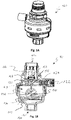
- FIG. 1A and 1B a well-known cut-off valve is shown, which is usually installed in caravans and mobile homes.
- This cut-off valve is set up so that it is closed when a specific acceleration is exceeded, thus preventing further gas flow. In this way, it is possible to prevent gas from getting into the gas line system downstream of the shut-off valve, for example in the event of an accident. This reduces the risk of gas leaks, for example in the event of an accident.
- the known shut-off valve 100 has a valve body which is made up of an upper element 116 and a lower element 118 .
- the upper element 116 has a gas inlet 102 and the lower element 118 has a gas outlet 104.
- a closure device 106 is arranged between the gas inlet 102 and the gas inlet 104, which has a valve disk with a valve pin 108 extending axially therefrom.
- the closure device 106 is biased such that a sealing portion 107 of the closure device 106 is pressed against a corresponding valve seat 120 of the upper member 116 .
- the shut-off valve has a switching chamber 112, within which an inertial body designed as a ball 110 can be moved freely.
- an additional tapered surface 114 which forms the floor of the switch compartment and which tapers downwardly when the shut-off valve is properly aligned.
- An edge of this conical surface 114 forms a resting position for the ball 110.
- the closure device 106 is then in the closed position. Thus, gas is prevented from flowing from the gas inlet 102 to the gas outlet 104 . If the shut-off valve has been triggered by mistake, the user can click on the actuating element 122 press.
- This actuating element 122 has an inclined plane 124 which presses against a conical section 109 of the closure device 106 and thus forces the closure device 106 upwards. Due to the conical surface 114, the ball rolls back into its rest position and prevents the locking device 106 from closing again.
- the U.S. 4,314,120 relates to a shock responsive device.
- the U.S. 4,191,868 relates to a seismic shutdown device.
- the U.S. 3,109,441 relates to a quick-closing valve that responds to vibrations.
- the U.S. 2,853,089 relates to an attachment for a safety valve.
- the U.S. 3,995,710 relates to a shut-off valve having the features of the preamble of claim 1.
- the object of the invention is to provide an improved shut-off valve.
- it is desirable to improve the response of the shut-off valve to accelerations, to ensure faster return of the inertial body to the rest state, and/or to reduce the flow resistance of the shut-off valve.
- the term “up” refers to a direction and/or position defined with respect to the shut-off valve, which points upwards when the shut-off device is properly installed.
- the term “down” refers to a direction and/or position defined with respect to the shut-off valve, which points downwards when the shut-off device is properly installed.
- the invention relates to a shut-off valve, preferably a crash valve, for interrupting a gas flow.
- the shut-off valve comprises a gas inlet, a gas outlet, a closure device arranged between the gas inlet and the gas outlet in the direction of flow, and an inertial body mounted in an oscillating manner.
- the closure device is movable along a direction of movement from an open position to a closed position. Furthermore, the closure device is biased into the closed state.
- the closure device also comprises a support element, preferably a structure protruding in the direction of movement, which is moved together with the closure device so that the support element assumes a first position in the open state and a second position in the closed state.
- the inertial body is set up, a rest position, in which the inertial body is aligned parallel to a first axis defined by the direction of movement of the closure device, and a deflected position, in which the inertial body is inclined with respect to the first axis, to take
- the inertial body is set up to automatically return from the deflected position to the rest position.
- the inertia body holds the support member in the first position, so that the shutter is prevented from returning to the closed position.
- the inertial body is also set up such that it is moved from the rest position to the deflected position when a predetermined acceleration is exceeded by an occurring acceleration force, so that the support element assumes the second position and the closure device assumes the closed state.
- the inertial body is arranged in the flow path between the gas inlet and gas outlet.
- the support element prevents the inertial body from returning to the rest position when the inertial body is in the deflected position and the support element is in the second position.
- the shut-off valve is thus designed in such a way that it is closed when a predetermined acceleration is exceeded, so that gas is prevented from flowing from the gas inlet to the gas outlet. In this way, leaks can be prevented downstream of the shut-off valve, particularly in traffic accidents.
- the cut-off valve according to the invention is particularly suitable to be installed in caravans, motor homes or the like in order to prevent the occurrence of gas leakage after traffic accidents.
- the closing device can be understood to mean an element which can be moved from the open position to the closed position and vice versa and in the process closes or opens the shut-off valve.
- the closure device can also be referred to as a closure element.
- the feature that the closure device is pretensioned in the closed state means that the closure device is pretensioned, for example by means of a spring element, and this pretension acts in the direction of the closed state. This means that the closure device is forced or pressed into the closed state, for example by the spring element.
- the spring element can in particular be a spiral spring.
- the inertial body is mounted in an oscillating manner can be understood to mean that the inertial body cannot be moved freely in the switching room. Instead is the Inertial bodies mounted in an oscillating and/or pivoting manner on a bearing formed in the control room. This means that at the point where the inertial body is mounted on the bearing, a pivot point is defined at which the inertial body is essentially pivotably mounted.
- the inertial body can be pivoted about a pivot axis that extends perpendicularly to the locking direction and/or horizontally, preferably about several axes.
- the term “essentially” means that the inertial body can also perform small translational movements, which are negligible compared to the pivoting movement of the inertial body and do not impair the function of the oscillatingly mounted inertial body.
- This oscillating mounting of the inertial body means that the triggering behavior of the inertial body can be controlled more precisely.
- the triggering of the inertial body is to be understood as meaning the process in which the inertial body is transferred from its rest position to the inclined position.
- an oscillating inertial body also has the advantage that it returns to its resting state more quickly than a freely movable body (e.g. a ball). In this way, a more reliable and faster switching back of the shut-off valve to the open state can be ensured.
- a freely movable body e.g. a ball
- the resting position of the inertial body can be understood to mean a more favorable energetic position than the deflected position of the inertial body.
- the inertial body can have a lower potential energy in the resting state than in the tilted state of the inertial body.
- the potential energy can be, for example, the potential energy of the inertial body.
- the potential energy can also include tension energy of a spring, by means of which the inertial body is mounted in an oscillating manner.
- the idle state can be an upright state in the assembly position of the shut-off valve, in which a longitudinal or rotational axis of the inertial body is essentially perpendicular. Because the resting position of the inertial body is energetically more favorable than the deflected position of the inertial body, the inertial body automatically returns from the deflected position to the resting position.
- the predetermined acceleration can be, for example, an acceleration that typically occurs in rear-end collisions or other accidents.
- Preferably the predetermined acceleration is at least 2 g, particularly preferably at least 3 g.
- the open position of the shut-off valve or the closure device can be understood to mean a state of the shut-off valve or the closure device in which gas can flow or can flow from the gas inlet to the gas outlet.
- the closed position can be understood to mean a state in which the closure device prevents gas from flowing or flowing from the gas inlet to the gas outlet.
- inertial body is set up to assume a rest position in which the inertial body is parallel to the first axis
- a longitudinal and/or rotational axis of the inertial body is parallel to the first axis in the rest position.
- the supporting element of the closure device can be understood to mean a structure of the closure device with which the closure device is supported on the inertial body. This support element can preferably protrude along the direction of movement of the closure device, preferably downwards.
- the inertial body can preferably be deflected in any direction. That is, in the rest position, the inertial body is arranged so that a longitudinal and/or rotational axis of the inertial body is parallel to the first axis defined by the direction of movement through the closure device. The inertial body can thus be tiltable in any direction relative to this axis.
- the shut-off valve preferably has a valve body.
- the valve body can be understood to mean the housing of the shut-off valve, which accommodates the closure device and/or the inertial body.
- the valve body can form the gas inlet and/or the gas outlet.
- This valve body can be designed in one or more parts.
- the valve body can have an upper part which contains the gas inlet forms and includes the closure device, and a lower part, which forms the gas outlet and together with the upper part forms a switching space for the inertial body.
- the inertial body can also be arranged outside of the valve body.
- the support element can be connected to the closure element via a lever mechanism, for example.
- the closure device preferably has a valve disk and a corresponding valve seat on the valve body.
- the valve disk can be designed to lie against the valve seat and/or to press against the valve seat when the closure device is in the closed state.
- the valve disk can be at a distance from the valve seat, so that gas can flow through between the valve disk and the valve seat.
- the valve disk can, for example, be covered by a seal, e.g. B. an O-ring or other annular seal, z. B. an annular sealing lip surrounded.
- the valve seat can be, for example, a conical annular structure of the valve body.
- the closure device is preferably rotationally symmetrical about an axis of rotation.
- the valve disk preferably lies in a plane that is perpendicular to the axis of rotation of the closure device.
- the support element is preferably a valve pin or a valve needle which protrudes in the direction of movement of the closure device.
- valve pin or the valve needle preferably extends along the axis of rotation.
- valve pin or the valve needle preferably extends axially away from the valve head.
- the support element is a valve pin or a valve needle
- the support surface on the inertial body can be relatively small. This makes it possible to ensure a more precise triggering behavior of the shut-off valve.
- the valve pin is preferably formed integrally on the valve disk.
- the valve body preferably has a switching space for the inertial body. That is, the valve body can form a switching space for the inertial body.
- the switching space can be understood to mean a volume or interior space within the valve body, in which the inertial body can move. However, that does not mean that the inertial body must be able to move freely in the switch room.
- the flow path between the gas inlet and the gas outlet preferably leads at least partially through the control room. More preferably, the control room is arranged downstream of the closure device and upstream of the gas outlet. In this way, the control room does not have to be sealed off from the gas path. This allows for a simpler and more reliable shut-off valve design.
- the supporting element prevents the inertial body from returning to the rest position when the inertial body is in the deflected position and the supporting element is in the second position.
- shut-off valve does not automatically return to the open state, although the inertial body is set up to independently attempt to return from the deflected position to the rest position.
- the support member engages the inertial body to prevent the inertial body from returning to the rest position when the inertial body is in the deflected position and the support member is in the second position.
- the inertial body is held in a defined deflected position after the shut-off valve has been triggered. This causes the inertial body to return from a defined deflected position to the rest position when the engagement of the support element in the inertial body is terminated. In this way the shut-off valve has a defined return behavior to the open position.
- the support element engages a groove of the inertial body to prevent the inertial body from returning to the rest position when the inertial body is in the deflected position and the support element is in the second position.
- the inertial body is preferably mounted in an oscillating and/or pivoting manner on a bearing, in particular a bearing surface of the bearing.
- This storage can be arranged in the control room of the shut-off valve.
- the bearing preferably has an opening through which a section of the inertial body protrudes.
- the opening in the bearing can be dimensioned in such a way that the inertial body can essentially only perform an oscillating movement and practically no translation of the inertial body takes place.
- the diameter of the opening for this purpose is no more than 33% larger than the diameter of the section of the inertial body that protrudes through the opening.
- the diameter of the opening in the bearing is 4 mm and the portion of the inertial body lying in the opening in the bearing is 3 mm.
- the opening is at the intersection of the bearing with the first axis.
- shut-off valve In this way, a symmetrical design of the shut-off valve can be achieved, which causes the shut-off valve to exhibit the same or a similar triggering behavior in every direction.
- the bearing has a conical surface tapering along the first axis and toward the protruding structure.
- the bearing is preferably designed conically upwards. In this way, more freedom of movement can be made possible for the oscillatingly mounted inertial body will.
- the bearing is formed in the control room of the valve body.
- the bearing can be an additional component that is inserted or pressed into the switching space; alternatively, the bearing can also be formed integrally on the part of the valve body that forms the switching space.
- the inertial body is preferably essentially rotationally symmetrical with respect to an axis of symmetry. In the rest position of the inertial body, the axis of symmetry is preferably parallel to the first axis.
- the inertial body shows the same or a similar triggering behavior in every direction.
- the statement “substantially” can be understood to mean that the inertial body can certainly have structures that disturb the above-mentioned symmetry. However, these structures do not prevent the inertial body from having the same triggering behavior in every direction.
- the inertial body is arranged between the gas inlet and the gas outlet in the flow path. In this way it is not necessary to seal off the inertial body from the flow path. This allows for a simpler and more reliable shut-off valve design.
- the inertial body preferably has a pendulum head arranged between the bearing and the projecting part and a pendulum arm projecting through the opening in the bearing.
- the diameter of the pendulum arm is 3 mm.
- the pendulum head preferably has a centrally arranged projection on its upper side and one or more indentations arranged around it, in particular a groove, so that the support element is supported on the projection of the pendulum head when the valve is open and the support element is in engages the groove of the valve head.
- the inertial body preferably has a support surface at the transition between the pendulum head and the pendulum arm, which is mounted or rests on the bearing when the inertial body is in the rest position.
- a step is formed at the transition between the pendulum head and the pendulum arm, which forms the support surface of the inertial body.
- the bearing has a downwardly sloping bearing surface around the opening and/or opposite the support surface of the inertial body.
- the bearing has a conical surface tapering along the first axis and toward the protruding structure.
- the support surface of the inertial body preferably rests only on an edge formed by the opening provided in the bearing.
- the center of gravity of the inertial body is preferably between the bearing and an upper end of the pendulum head. In other words, the center of gravity is between the bearing and the locking device.
- the inertial body is particularly preferably mounted in an oscillating manner by means of a spring element, which presses the support surface of the inertial body against the bearing.
- the shut-off valve preferably has a spring element which is arranged around the pendulum arm on the side of the bearing opposite the pendulum head. Furthermore, the pendulum arm preferably has a fixing element to hold the spring element on the pendulum arm to fix. The spring element tensions the inertial body against the bearing. That is, the spring element forces the support surface against the bearing.
- the spring element can be a spiral spring.
- the spring element can ensure that the inertial body can only carry out an oscillating movement and practically no translational movement.
- the spring element ensures that the inertial body returns to the idle state particularly quickly.
- the spring element can ensure that the center of gravity of the inertial body can be above the bearing, so that the inertial body and thus also the shut-off valve take up less space.
- the pendulum arm preferably has a counterweight on the side of the bearing opposite the pendulum head.
- this counterweight has the effect that the inertial body is pulled downwards by the weight force in the assembly position of the shut-off valve, so that the support surface of the inertial body is forced against the bearing.
- the counterweight causes the inertial body to quickly return to its resting state.
- the counterweight preferably protrudes into a section of the gas outlet.
- the weight of the inertial body is preferably between 5 grams and 20 grams, preferably between 10 grams and 20 grams.
- the valve preferably has an actuating element with which the closure device can be switched from the closed state to the open state and at the same time the support element can be switched from the second position to the first position, so that the inertial body can independently return to its rest position.
- the actuating element can be moved along a direction that is perpendicular to the first axis.
- the actuating element can have a surface which is inclined in this direction. When the actuating element is actuated, this inclined surface can press against a conical surface of the closure device, so that the closure device is pressed into the open state.
- the valve preferably has an indicator element which indicates that the closure device is in the open and/or closed position.
- the indicator element is preferably attached to the valve so that it can rotate about a second axis and has an eccentric which engages in the closure device in such a way that the indicator element has a first angle of rotation in the open position of the closure device and a second angle of rotation in the closed position of the closure device. More preferably, when closing and/or opening, the display element performs a rotation that is greater than 0° and less than 360°. Even more preferably, the display element rotates through an angle that is between 75° and 105°.
- a further embodiment of the invention relates to a gas line system with a shut-off valve as described herein.
- a further embodiment of the invention relates to a vehicle, aircraft or boat, preferably a caravan or a mobile home, with a shut-off valve as described herein or a gas line system as described herein.
- caravan also includes mobile homes.
- mobile home also includes mobile homes, motorhomes, motor caravans and/or camper vans.
- the shut-off valve 200 has a valve body which is formed by an upper valve body part 216 and a lower valve body part 218 . Furthermore, the shut-off valve 200 comprises a gas inlet 202, which is formed by the upper valve body part 216 in this case, and a gas outlet 204, which is formed by the lower valve body part 218 in this case.
- the shut-off valve also has a closure device 206 .
- the closure device 206 comprises a valve disk 205 , a valve pin or a valve needle 208 , and a valve stem 236 which is arranged on the side of the valve disk 205 opposite the valve pin or the valve needle 208 .
- the valve stem 236 is slidably mounted in a guide 238 which is arranged, e.g. pressed, in the gas inlet area of the valve body.
- the closure device has an annular seal 207 , for example an O-ring or an annular lip seal, which is arranged around the valve disk 205 .
- a first spring element 248 which urges the closure device 206 downwardly into the closed position.
- the closure device 206 is prestressed into the closed position by means of the first spring element 248 .
- the seal 207 arranged around the valve disk 205 is pressed against a corresponding valve seat 220, which is formed on the valve body.
- the valve seat 220 can be designed as a conical surface, for example.
- the shut-off valve 200 also has a switching chamber 212 which is formed in the lower valve body part 218 and is closed off from above by the upper valve body part 216 .
- the inertial body 210 is located in the control room 212.
- the inertial body 210 is mounted on a bearing 214 in an oscillating manner. That is, the bearing 214 has an opening through which a pendulum arm 228 of the inertial body 210 protrudes.
- the inertia body 210 also has a pendulum head 226 which is arranged between the bearing 214 and the valve pin or valve needle 208 .
- the pendulum head 226 has a center arranged projection 230 and a groove 232 arranged around it.
- the support surface rests only on an edge which is formed by and surrounds the opening provided in the bearing 214 .
- a second spring element 250 which is arranged around the pendulum arm 228 , is arranged on the side of the bearing 214 opposite the pendulum head 226 .
- This second spring element 250 is attached at one end to a distal end of the pendulum arm 228 by means of the fixation 234 .
- the opposite end of the second spring element 250 presses against the lower side of the bearing 214.
- the inertial body 210 is pressed against the bearing 214 by the second spring element 250 and at the same time also in an upright position, i.e. rest position of the inertial body 210.
- a supporting surface of the inertial body 210 is pressed against a corresponding part of the bearing 214 by the second spring element 250 .
- the shut-off valve 200 has an actuating element 222 .
- the actuating element 222 is slidably arranged in the upper valve body part 216 of the valve body in such a way that it can be moved perpendicularly to the direction of movement of the closure device 206 .
- the actuator 222 has a tapered surface 224 that is inclined relative to the direction of movement of the actuator 222 . Upon actuation of the actuator 222, the tapered surface 224 presses against a corresponding surface of the closure device 206, which surface may be conical.
- Shut-off valve 200 also has an indicator element 242 .
- the display element 242 is rotatably mounted in the valve body, here in the upper part 216 of the valve body. This means that the display element can be rotated about an axis of rotation that is perpendicular to the direction of movement of the closure device 206 .
- the display element 242 has an eccentric 244 which engages in a groove 240 of the closure device. The eccentric is offset relative to the axis of rotation of the display element 242, i.e. eccentric to the axis of rotation of the display element 242. When the closure device 206 is moved downwards or upwards, this movement of the closure device 206 causes the display element 242 to rotate by means of the eccentric 244.
- FIG 2A the open state of the shut-off valve 200 is shown.
- the valve pin or valve needle 208 is supported on the inertial body 210, more precisely on the projection 230 of the pendulum head 226 of the inertial body 210.
- the first spring element 248 is prestressed when the shut-off valve 200 is in the open state. If an acceleration now occurs that exceeds the predefined acceleration, the inertial body 210 is pushed by the in Figure 2A shown rest position deflected. This state is in Figure 2B shown.
- FIG 2B shows the state of the shut-off valve 200 in which the inertial body 210 is inclined. This state is present after an acceleration that has exceeded the predefined acceleration.
- the prestressing of the closure device 206 by means of the first spring element 248 causes the closure device 206 to be pressed into the closed position by the first spring element 248, since the valve pin or the valve needle 208 can no longer be supported on the central projection 230.
- the valve pin or the valve needle 208 protrudes into the groove 232 or engages in the groove 232 .
- the seal 207 presses against the valve seat 220.
- the valve pin or valve pin 208 engages the groove 232 of the inertial body 210, the valve pin or valve pin 208 prevents the inertial body 210 from returning to its rest position.
- the inclined surface 224 is pressed against the surface 209 of the closure device 206, which causes a vertical movement of the closure device 206 upwards.
- the valve pin or the valve needle 208 is thus also moved upwards, so that it no longer engages in the groove 232 of the inertial body 210 .
- the second spring element 250 pushes the inertial body 210 back into its upright position of rest.
- the valve pin or the valve needle 208 is supported on the central projection 230 of the inertial body 210, so that the shut-off valve is held in the open state again, as is shown in FIG Figure 2A is shown.
- shut-off valve 300 according to a further exemplary embodiment of the invention is shown.
- the elements that differ from those in the Figures 2A and 2B shown shut-off valve differ. All other elements are identical to those in Figures 2A and 2B items shown.
- the shut-off valve 300 has an inertial body 310 .
- the inertial body 310 also has a pendulum arm 328 which extends through an opening in the bearing.
- a counterweight 346 is attached to the lower, ie distal, end of the pendulum arm 328 .
- This counterweight 346 preferably protrudes into the gas outlet area 304 .
- the counterweight can be formed by the pendulum arm 328 itself.
- the counterweight 346 is formed as a distinguishable structure at the lower end of the pendulum arm 328, as shown in FIG 3 shown.
- the counterweight 346 of the embodiment of FIG 3 can also be included in the embodiment of Figures 2A and 2B be provided, i.e. also in combination with the spring element 250.
- FIG. 4 1 shows a vehicle 400 according to a further exemplary embodiment of the invention.
- the vehicle 400 is a mobile home, but the vehicle can also be a camping bus, a caravan or a mobile home.
- the vehicle 400 has a gas line system 406 .
- the gas line system 406 includes, among other things, a gas source or a gas bottle 402 and a shut-off valve 404 connected thereto, which is designed as described herein.
Description
Die Erfindung betrifft ein Abschaltventil, ein Gasleitungssystem und ein Fahrzeug.The invention relates to a shut-off valve, a gas line system and a vehicle.
In den
Das bekannte Abschaltventil 100 hat einen Ventilkörper, der aus einem oberen Element 116 und einem unteren Element 118 aufgebaut ist. Das obere Element 116 hat einen Gaseinlass 102 und das untere Element 118 einen Gasauslass 104. Zwischen dem Gaseinlass 102 und dem Gaseinlass 104 ist eine Verschlusseinrichtung 106 angeordnet, die einen Ventilteller mit einem sich axial davon erstreckenden Ventilstift 108 aufweist. Die Verschlusseinrichtung 106 ist derart vorgespannt, dass ein Dichtungsabschnitt 107 der Verschlusseinrichtung 106 gegen einen entsprechenden Ventilsitz 120 des oberen Elements 116 gedrückt wird. Weiterhin weist das Abschaltventil einen Schaltraum 112 auf, innerhalb dessen ein als Kugel 110 ausgebildeter Trägheitskörper frei bewegbar ist. Innerhalb des Abschaltventils befindet sich eine zusätzliche konische Fläche 114, die den Boden des Schaltraums bildet und die bei korrekter Ausrichtung des Abschaltventils nach unten konisch zuläuft. Eine Kante dieser konischen Fläche 114 bildet eine Ruheposition für die Kugel 110. Wenn sich die Kugel 110 in der Ruheposition befindet, drückt die Kugel den Ventilstift 108 nach oben, sodass die Dichtung 107 von dem Ventilsitz 120 beabstandet ist, sodass sich die Verschlusseinrichtung 106 in der offenen Position befindet. Auf diese Weise kann Gas vom Gaseinlass 102 zum Gasauslass 104 fließen. Bei Auftreten einer Beschleunigung, die die vorbestimmte Beschleunigung überschreitet, wird die Kugel 110 von ihrer Ruheposition wegbewegt, sodass der Ventilstift 108 aufgrund der Vorspannung der Verschlusseinrichtung 106 nach unten bewegt wird und die Dichtung 107 gegen den Ventilsitz 120 gepresst wird. Die Verschlusseinrichtung 106 befindet sich dann in der geschlossenen Position. Somit wird verhindert, dass Gas vom Gaseinlass 102 zum Gasauslass 104 fließt. Sollte das Abschaltventil fälschlicherweise ausgelöst worden sein, kann der Benutzer auf das Betätigungselement 122 drücken. Dieses Betätigungselement 122 weist eine schiefe Ebene 124 auf, die gegen einen konischen Abschnitt 109 der Verschlusseinrichtung 106 drückt und so die Verschlusseinrichtung 106 nach oben zwingt. Aufgrund der konischen Fläche 114 rollt die Kugel in ihre Ruheposition zurück und verhindert wieder ein Verschließen der Verschlusseinrichtung 106.The known shut-off
Die
Die
Die
Die
Die
Aufgabe der Erfindung ist es, ein verbessertes Abschaltventil bereitzustellen. Insbesondere ist es wünschenswert, das Ansprechverhalten des Abschaltventils auf Beschleunigungen zu verbessern, ein schnelleres Zurückkehren des Trägheitskörpers in den Ruhezustand sicherzustellen und/oder den Strömungswiderstand des Abschaltventils zu verringern.The object of the invention is to provide an improved shut-off valve. In particular, it is desirable to improve the response of the shut-off valve to accelerations, to ensure faster return of the inertial body to the rest state, and/or to reduce the flow resistance of the shut-off valve.
Diese Aufgaben werden zumindest teilweise durch den Gegenstand des unabhängigen Anspruchs gelöst. Weitere Ausführungsformen der Erfindung sind in den abhängigen Ansprüchen, der Beschreibung und den Figuren offenbart.These objects are at least partially solved by the subject matter of the independent claim. Further embodiments of the invention are disclosed in the dependent claims, the description and the figures.
Im Rahmen der Erfindung bezeichnet der Begriff "oben" eine bezüglich des Abschaltventils definierte Richtung und/oder Position, die bei einer ordnungsgemäß montierten Abschalteinrichtung nach oben zeigt. Entsprechend bezeichnet der Begriff "unten" eine bezüglich des Abschaltventils definierte Richtung und/oder Position, die bei einer ordnungsgemäß montierten Abschalteinrichtung nach unten zeigt.In the context of the invention, the term “up” refers to a direction and/or position defined with respect to the shut-off valve, which points upwards when the shut-off device is properly installed. Correspondingly, the term "down" refers to a direction and/or position defined with respect to the shut-off valve, which points downwards when the shut-off device is properly installed.
Die Erfindung betrifft ein Abschaltventil, vorzugsweise Crash-Ventil, zum Unterbrechen eines Gasdurchflusses. Das Abschaltventil umfasst einen Gaseinlass, einen Gasauslass, eine in Strömungsrichtung zwischen Gaseinlass und Gasauslass angeordnete Verschlusseinrichtung sowie einen pendelnd gelagerten Trägheitskörper. Die Verschlusseinrichtung ist entlang einer Bewegungsrichtung von einer offenen Position in eine geschlossene Position bewegbar. Ferner ist die Verschlusseinrichtung in den geschlossenen Zustand vorgespannt. Die Verschlusseinrichtung umfasst außerdem ein Abstützelement, vorzugsweise eine in der Bewegungsrichtung vorstehende Struktur, das zusammen mit der Verschlusseinrichtung bewegt wird, sodass das Abstützelement im offenen Zustand eine erste Position und im geschlossenen Zustand eine zweite Position einnimmt. Der Trägheitskörper ist eingerichtet, eine Ruheposition, in der der Trägheitskörper parallel zu einer durch die Bewegungsrichtung der Verschlusseinrichtung definierten ersten Achse ausgerichtet ist, und eine ausgelenkte Position, in der der Trägheitskörper bezüglich der ersten Achse geneigt ist, einzunehmen. Der Trägheitskörper ist eingerichtet, selbstständig von der ausgelenkten Position in die Ruheposition zurückzukehren. In der Ruheposition hält der Trägheitskörper das Abstützelement in der ersten Position, sodass die Verschlusseinrichtung daran gehindert wird, in die geschlossene Position zurückzukehren. Der Trägheitskörper ist ferner eingerichtet, dass er bei Überschreiten einer vorbestimmten Beschleunigung durch eine auftretende Beschleunigungskraft von der Ruheposition in die ausgelenkte Position bewegt wird, sodass das Abstützelement die zweite Position und die Verschlusseinrichtung den geschlossenen Zustand einnehmen. Der Trägheitskörper ist zwischen Gaseinlass und Gasauslass im Strömungspfad angeordnet. Zudem hindert das Abstützelement den Trägheitskörper daran, in die Ruheposition zurückzukehren, wenn sich der Trägheitskörper in der ausgelenkten und das Abstützelement in der zweiten Position befinden.The invention relates to a shut-off valve, preferably a crash valve, for interrupting a gas flow. The shut-off valve comprises a gas inlet, a gas outlet, a closure device arranged between the gas inlet and the gas outlet in the direction of flow, and an inertial body mounted in an oscillating manner. The closure device is movable along a direction of movement from an open position to a closed position. Furthermore, the closure device is biased into the closed state. The closure device also comprises a support element, preferably a structure protruding in the direction of movement, which is moved together with the closure device so that the support element assumes a first position in the open state and a second position in the closed state. The inertial body is set up, a rest position, in which the inertial body is aligned parallel to a first axis defined by the direction of movement of the closure device, and a deflected position, in which the inertial body is inclined with respect to the first axis, to take The inertial body is set up to automatically return from the deflected position to the rest position. In the rest position, the inertia body holds the support member in the first position, so that the shutter is prevented from returning to the closed position. The inertial body is also set up such that it is moved from the rest position to the deflected position when a predetermined acceleration is exceeded by an occurring acceleration force, so that the support element assumes the second position and the closure device assumes the closed state. The inertial body is arranged in the flow path between the gas inlet and gas outlet. In addition, the support element prevents the inertial body from returning to the rest position when the inertial body is in the deflected position and the support element is in the second position.
Das Abschaltventil ist somit derart ausgestaltet, dass es bei Überschreiten einer vorbestimmten Beschleunigung geschlossen wird, sodass Gas daran gehindert wird, vom Gaseinlass zum Gasauslass zu fließen. Auf diese Weise können insbesondere bei Verkehrsunfällen stromabwärts des Abschaltventils Leckagen verhindert werden.The shut-off valve is thus designed in such a way that it is closed when a predetermined acceleration is exceeded, so that gas is prevented from flowing from the gas inlet to the gas outlet. In this way, leaks can be prevented downstream of the shut-off valve, particularly in traffic accidents.
Das erfindungsgemäße Abschaltventil ist besonders geeignet, um in Wohnwägen, Reisemobile oder dergleichen installiert zu werden, um das Auftreten von Gasleckagen nach Verkehrsunfällen zu verhindern.The cut-off valve according to the invention is particularly suitable to be installed in caravans, motor homes or the like in order to prevent the occurrence of gas leakage after traffic accidents.
Unter der Verschlusseinrichtung kann dabei ein Element verstanden werden, welches von der offenen Position in die geschlossene Position und umgekehrt bewegbar ist und dabei das Abschaltventil schließt bzw. öffnet. Die Verschlusseinrichtung kann auch als Schließelement bezeichnet werden. Unter dem Merkmal, dass die Verschlusseinrichtung in den geschlossenen Zustand vorgespannt ist, ist zu verstehen, dass die Verschlusseinrichtung beispielsweise mittels eines Federelements vorgespannt ist und diese Vorspannung in Richtung des geschlossenen Zustands wirkt. Das bedeutet, dass die Verschlusseinrichtung in den geschlossenen Zustand gezwungen bzw. gedrückt wird, z.B. durch das Federelement. Das Federelement kann insbesondere eine Spiralfeder sein.The closing device can be understood to mean an element which can be moved from the open position to the closed position and vice versa and in the process closes or opens the shut-off valve. The closure device can also be referred to as a closure element. The feature that the closure device is pretensioned in the closed state means that the closure device is pretensioned, for example by means of a spring element, and this pretension acts in the direction of the closed state. This means that the closure device is forced or pressed into the closed state, for example by the spring element. The spring element can in particular be a spiral spring.
Unter dem Merkmal dass der Trägheitskörper pendelnd gelagert ist, kann verstanden werden, dass der Trägheitskörper nicht frei im Schaltraum bewegbar ist. Stattdessen ist der Trägheitskörper pendelnd und/oder schwenkbar auf einer im Schaltraum ausgebildeten Lagerung gelagert. Das heißt, dass an dem Punkt, wo der Trägheitskörper auf der Lagerung gelagert ist, ein Drehpunkt definiert wird, an dem der Trägheitskörper im Wesentlichen schwenkbar gelagert ist. Der Trägheitskörper kann insbesondere um eine Schwenkachse geschwenkt werden, die sich senkrecht zur Verschlussrichtung und/oder horizontal erstreckt, vorzugsweise um mehrere Achsen. Unter der Angabe "im Wesentlichen" ist zu verstehen, dass der Trägheitskörper auch kleine translatorische Bewegungen durchführen kann, die jedoch im Vergleich zur Schwenkbewegung des Trägheitskörpers vernachlässigbar sind und die Funktion des pendelnd gelagerten Trägheitskörpers nicht beeinträchtigen.The feature that the inertial body is mounted in an oscillating manner can be understood to mean that the inertial body cannot be moved freely in the switching room. Instead is the Inertial bodies mounted in an oscillating and/or pivoting manner on a bearing formed in the control room. This means that at the point where the inertial body is mounted on the bearing, a pivot point is defined at which the inertial body is essentially pivotably mounted. In particular, the inertial body can be pivoted about a pivot axis that extends perpendicularly to the locking direction and/or horizontally, preferably about several axes. The term “essentially” means that the inertial body can also perform small translational movements, which are negligible compared to the pivoting movement of the inertial body and do not impair the function of the oscillatingly mounted inertial body.
Diese pendelnde Lagerung des Trägheitskörpers bewirkt, dass das Auslöseverhaltens des Trägheitskörpers genauer kontrolliert werden kann. Unter dem Auslösen des Trägheitskörpers ist dabei der Vorgang zu verstehen, bei dem der Trägheitskörper von seiner Ruheposition in die geneigte Position überführt wird.This oscillating mounting of the inertial body means that the triggering behavior of the inertial body can be controlled more precisely. The triggering of the inertial body is to be understood as meaning the process in which the inertial body is transferred from its rest position to the inclined position.
Außerdem hat ein pendelnd gelagerter Trägheitskörper auch den Vorteil, dass er im Vergleich zu einem frei bewegbaren Körper (z.B. eine Kugel) schneller in seinen Ruhezustand zurückkehrt. Auf diese Weise kann ein zuverlässigeres und schnelleres Zurückschalten des Abschaltventils in den offenen Zustand gewährleistet werden.In addition, an oscillating inertial body also has the advantage that it returns to its resting state more quickly than a freely movable body (e.g. a ball). In this way, a more reliable and faster switching back of the shut-off valve to the open state can be ensured.
Unter der Ruheposition des Trägheitskörpers kann eine im Vergleich zur ausgelenkten Position des Trägheitskörpers günstigere energetische Position verstanden werden. Zum Beispiel kann der Trägheitskörper im Ruhezustand eine geringere potenzielle Energie aufweisen als im geneigten Zustand des Trägheitskörpers. Die potentielle Energie kann beispielsweise die Lageenergie des Trägheitskörpers sein. Die potentielle Energie kann auch eine Spannenergie einer Feder umfassen, mittels welcher der Trägheitskörper pendelnd gelagert ist. Der Ruhezustand kann dabei in der Montageposition des Abschaltventils ein aufrechter Zustand sein, in dem eine Längs- bzw. Rotationsachse des Trägheitskörpers im Wesentlichen im Lot ist. Indem die Ruheposition des Trägheitskörpers energetisch günstiger ist als die ausgelenkte Position des Trägheitskörpers, kehrt der Trägheitskörper selbstständig von der ausgelenkten Position in die Ruheposition zurück.The resting position of the inertial body can be understood to mean a more favorable energetic position than the deflected position of the inertial body. For example, the inertial body can have a lower potential energy in the resting state than in the tilted state of the inertial body. The potential energy can be, for example, the potential energy of the inertial body. The potential energy can also include tension energy of a spring, by means of which the inertial body is mounted in an oscillating manner. The idle state can be an upright state in the assembly position of the shut-off valve, in which a longitudinal or rotational axis of the inertial body is essentially perpendicular. Because the resting position of the inertial body is energetically more favorable than the deflected position of the inertial body, the inertial body automatically returns from the deflected position to the resting position.
Bei der vorbestimmten Beschleunigung kann es sich beispielsweise um eine Beschleunigung handeln, die typischerweise bei Auffahrunfällen oder anderen Unfällen auftritt. Vorzugsweise beträgt die vorbestimmte Beschleunigung mindestens 2 g, besonders bevorzugt mindestens 3 g.The predetermined acceleration can be, for example, an acceleration that typically occurs in rear-end collisions or other accidents. Preferably the predetermined acceleration is at least 2 g, particularly preferably at least 3 g.
Unter der offenen Position des Abschaltventils bzw. der Verschlusseinrichtung kann ein Zustand des Abschaltventils bzw. der Verschlusseinrichtung verstanden werden, bei dem Gas vom Gaseinlass zum Gasauslass fließen bzw. strömen kann. Entsprechend kann unter der geschlossenen Position ein Zustand verstanden werden, bei dem die Verschlusseinrichtung Gas daran hindert, vom Gaseinlass zum Gasauslass zu fließen bzw. zu strömen.The open position of the shut-off valve or the closure device can be understood to mean a state of the shut-off valve or the closure device in which gas can flow or can flow from the gas inlet to the gas outlet. Correspondingly, the closed position can be understood to mean a state in which the closure device prevents gas from flowing or flowing from the gas inlet to the gas outlet.
Darunter, dass der Trägheitskörper eingerichtet ist, eine Ruheposition einzunehmen, in der der Trägheitskörper parallel zur ersten Achse ist, kann verstanden werden, dass eine Längs- und/oder Rotationsachse des Trägheitskörpers in der Ruheposition parallel zur ersten Achse ist.The fact that the inertial body is set up to assume a rest position in which the inertial body is parallel to the first axis can be understood to mean that a longitudinal and/or rotational axis of the inertial body is parallel to the first axis in the rest position.
Unter dem Abstützelement der Verschlusseinrichtung kann eine Struktur der Verschlusseinrichtung verstanden werden, mit welcher sich die Verschlusseinrichtung am Trägheitskörper abstützt. Dieses Abstützelement kann vorzugsweise entlang der Bewegungsrichtung der Verschlusseinrichtung hervorstehen, vorzugsweise nach unten.The supporting element of the closure device can be understood to mean a structure of the closure device with which the closure device is supported on the inertial body. This support element can preferably protrude along the direction of movement of the closure device, preferably downwards.
Vorzugsweise ist der Trägheitskörper in jede Richtung auslenkbar. Das heißt, in der Ruheposition ist der Trägheitskörper eingerichtet, damit eine Längs- und/oder Rotationsachse des Trägheitskörpers parallel zur ersten Achse ist, die durch die Bewegungsrichtung durch die Verschlusseinrichtung definiert ist. Gegenüber dieser Achse kann der Trägheitskörper somit in jede Richtung neigbar sein.The inertial body can preferably be deflected in any direction. That is, in the rest position, the inertial body is arranged so that a longitudinal and/or rotational axis of the inertial body is parallel to the first axis defined by the direction of movement through the closure device. The inertial body can thus be tiltable in any direction relative to this axis.
Dadurch kann gewährleistet werden, dass eine Beschleunigung entlang jeder Horizontalrichtung zum Auslösen des Abschaltventils führt. Somit kann die Zuverlässigkeit des Abschaltventils erhöht werden.This can ensure that an acceleration along any horizontal direction leads to the triggering of the shut-off valve. Thus, the reliability of the shut-off valve can be increased.
Vorzugsweise weist das Abschaltventil einen Ventilkörper auf. Unter dem Ventilkörper kann das Gehäuse des Abschaltventils verstanden werden, welches die Verschlusseinrichtung und/oder den Trägheitskörper beherbergt. Außerdem kann der Ventilkörper den Gaseinlass und/oder den Gasauslass ausbilden. Dieser Ventilkörper kann ein- oder mehrteilig ausgebildet sein. Beispielsweise kann der Ventilkörper ein oberes Teil aufweisen, welches den Gaseinlass ausbildet und die Verschlusseinrichtung umfasst, sowie ein unteres Teil, das den Gasauslass bildet und zusammen mit dem oberen Teil einen Schaltraum für den Trägheitskörper bildet. Der Trägheitskörper kann jedoch auch außerhalb des Ventilkörpers angeordnet sein. In diesem Fall kann das Abstützelement z.B. über einen Hebelmechanismus mit dem Verschlusselement verbunden sein.The shut-off valve preferably has a valve body. The valve body can be understood to mean the housing of the shut-off valve, which accommodates the closure device and/or the inertial body. In addition, the valve body can form the gas inlet and/or the gas outlet. This valve body can be designed in one or more parts. For example, the valve body can have an upper part which contains the gas inlet forms and includes the closure device, and a lower part, which forms the gas outlet and together with the upper part forms a switching space for the inertial body. However, the inertial body can also be arranged outside of the valve body. In this case, the support element can be connected to the closure element via a lever mechanism, for example.
Vorzugsweise weist die Verschlusseinrichtung einen Ventilteller und einen entsprechenden Ventilsitz am Ventilkörper auf. Dabei kann der Ventilteller ausgebildet sein, in geschlossenem Zustand der Verschlusseinrichtung am Ventilsitz anzuliegen und/oder gegen den Ventilsitz zu drücken. In geöffnetem Zustand der Verschlusseinrichtung kann der Ventilteller vom Ventilsitz beabstandet sein, sodass Gas zwischen dem Ventilteller und dem Ventilsitz hindurchströmen kann. Der Ventilteller kann beispielsweise von einer Dichtung, z. B. einem O-Ring oder einer anderen ringförmigen Dichtung, z. B. einer ringförmigen Dichtlippe, umgeben sein. Der Ventilsitz kann beispielsweise eine konische ringförmige Struktur des Ventilkörpers sein.The closure device preferably has a valve disk and a corresponding valve seat on the valve body. In this case, the valve disk can be designed to lie against the valve seat and/or to press against the valve seat when the closure device is in the closed state. When the closure device is in the open state, the valve disk can be at a distance from the valve seat, so that gas can flow through between the valve disk and the valve seat. The valve disk can, for example, be covered by a seal, e.g. B. an O-ring or other annular seal, z. B. an annular sealing lip surrounded. The valve seat can be, for example, a conical annular structure of the valve body.
Vorzugsweise ist die Verschlusseinrichtung um eine Rotationsachse rotationssymmentrisch. Der Ventilteller liegt in diesem Fall vorzugsweise in einer Ebene, die senkrecht zur Rotationsachse der Verschlusseinrichtung ist.The closure device is preferably rotationally symmetrical about an axis of rotation. In this case, the valve disk preferably lies in a plane that is perpendicular to the axis of rotation of the closure device.
Vorzugsweise ist das Abstützelement ein Ventilstift oder eine Ventilnadel, der bzw. die in der Bewegungsrichtung der Verschlusseinrichtung hervorsteht.The support element is preferably a valve pin or a valve needle which protrudes in the direction of movement of the closure device.
Im Falle dass die Verschlusseinrichtung um eine Rotationsachse rotationssymmetrisch ist, erstreckt sich der Ventilstift oder die Ventilnadel vorzugsweise entlang der Rotationsachse. Mit anderen Worten erstreckt sich der Ventilstift oder die Ventilnadel vorzugsweise axial von dem Ventilteller weg.If the closure device is rotationally symmetrical about an axis of rotation, the valve pin or the valve needle preferably extends along the axis of rotation. In other words, the valve pin or the valve needle preferably extends axially away from the valve head.
Dadurch, dass es sich beim Abstützelement um einen Ventilstift oder eine Ventilnadel handelt, kann die Abstützfläche auf dem Trägheitskörper relativ gering sein. Dadurch ist es möglich, ein präziseres Auslöseverhalten des Abschaltventils zu gewährleisten.Since the support element is a valve pin or a valve needle, the support surface on the inertial body can be relatively small. This makes it possible to ensure a more precise triggering behavior of the shut-off valve.
Vorzugsweise ist der Ventilstift integral am Ventilteller ausgebildet.The valve pin is preferably formed integrally on the valve disk.
Auf diese Weise kann eine technisch zuverlässige, gasdichte und einfache Konstruktion der Verschlusseinrichtung bereitgestellt werden.In this way, a technically reliable, gas-tight and simple construction of the closure device can be provided.
Vorzugsweise weist der Ventilkörper einen Schaltraum für den Trägheitskörper auf. Das heißt, der Ventilkörper kann einen Schaltraum für den Trägheitskörper bilden. Unter dem Schaltraum kann ein Volumen oder Innenraum innerhalb des Ventilkörpers verstanden werden, in welchem sich der Trägheitskörper bewegen kann. Das heißt aber nicht, dass der Trägheitskörper sich im Schaltraum frei bewegen können muss.The valve body preferably has a switching space for the inertial body. That is, the valve body can form a switching space for the inertial body. The switching space can be understood to mean a volume or interior space within the valve body, in which the inertial body can move. However, that does not mean that the inertial body must be able to move freely in the switch room.
Vorzugsweise führt der Strömungspfad zwischen Gaseinlass und Gasauslass zumindest teilweise durch den Schaltraum. Weiter bevorzugt ist der Schaltraum stromabwärts der Verschlusseinrichtung und stromaufwärts des Gasauslasses angeordnet. Auf diese Weise muss der Schaltraum nicht vom Gaspfad abgedichtet werden. Dies ermöglicht eine einfachere und zuverlässigere Konstruktion des Abschaltventils.The flow path between the gas inlet and the gas outlet preferably leads at least partially through the control room. More preferably, the control room is arranged downstream of the closure device and upstream of the gas outlet. In this way, the control room does not have to be sealed off from the gas path. This allows for a simpler and more reliable shut-off valve design.
Erfindungsgemäß hindert das Abstützelement den Trägheitskörper daran, in die Ruheposition zurückzukehren, wenn sich der Trägheitskörper in der ausgelenkten und das Abstützelement in der zweiten Position befinden.According to the invention, the supporting element prevents the inertial body from returning to the rest position when the inertial body is in the deflected position and the supporting element is in the second position.
Auf diese Weise kann gewährleistet werden, dass das Abschaltventil nicht selbstständig in den offenen Zustand zurückkehrt, obwohl der Trägheitskörper eingerichtet ist, selbstständig versucht, von der ausgelenkten Position in die Ruheposition zurückzukehren.In this way it can be ensured that the shut-off valve does not automatically return to the open state, although the inertial body is set up to independently attempt to return from the deflected position to the rest position.
Vorzugsweise greift das Abstützelement in den Trägheitskörper ein, um den Trägheitskörper daran zu hindern, in die Ruheposition zurückzukehren, wenn sich der Trägheitskörper in der ausgelenkten Position und sich das Abstützelement in der zweiten Position befinden.Preferably, the support member engages the inertial body to prevent the inertial body from returning to the rest position when the inertial body is in the deflected position and the support member is in the second position.
Auf diese Weise wird der Trägheitskörper in einer definierten ausgelenkten Position gehalten, nachdem das Abschaltventil ausgelöst wurde. Dies bewirkt, dass der Trägheitskörper von einer definierten ausgelenkten Position in die Ruheposition zurückkehrt, wenn der Eingriff des Abstützelements im Trägheitskörper beendet wird. Auf diese Weise hat das Abschaltventil ein definiertes Rückkehrverhalten in die offene Position.In this way, the inertial body is held in a defined deflected position after the shut-off valve has been triggered. This causes the inertial body to return from a defined deflected position to the rest position when the engagement of the support element in the inertial body is terminated. In this way the shut-off valve has a defined return behavior to the open position.
Vorzugsweise greift das Abstützelement in eine Nut des Trägheitskörpers ein, um den Trägheitskörper daran zu hindern, in die Ruheposition zurückzukehren, wenn sich der Trägheitskörper in der ausgelenkten Position und das Abstützelement in der zweiten Position befinden.Preferably, the support element engages a groove of the inertial body to prevent the inertial body from returning to the rest position when the inertial body is in the deflected position and the support element is in the second position.
Vorzugsweise ist der Trägheitskörper auf einer Lagerung pendelnd und/oder schwenkbar gelagert, insbesondere einer Lagerfläche der Lagerung.The inertial body is preferably mounted in an oscillating and/or pivoting manner on a bearing, in particular a bearing surface of the bearing.
Diese Lagerung kann im Schaltraum des Abschaltventils angeordnet sein.This storage can be arranged in the control room of the shut-off valve.
Vorzugsweise weist die Lagerung eine Öffnung auf, durch die ein Abschnitt des Trägheitskörpers hindurch ragt.The bearing preferably has an opening through which a section of the inertial body protrudes.
Auf diese Weise kann eine pendelnde Lagerung des Trägheitskörpers erreicht werden, die eine einfache und somit robuste und zuverlässige Konstruktion aufweist. Ferner kann die Öffnung in der Lagerung derart dimensioniert sein, dass der Trägheitskörper im Wesentlichen nur eine pendelnde Bewegung durchführen kann und praktisch keine Translation des Trägheitskörpers erfolgt. Beispielsweise ist der Durchmesser der Öffnung hierfür nicht mehr als 33% größer als der Durchmesser des Abschnitts des Trägheitskörpers, der durch die Öffnung hindurch ragt. Beispielsweise betragen der Durchmesser der Öffnung in der Lagerung 4 mm und der Abschnitt des Trägheitskörpers, der in der Öffnung der Lagerung liegt, 3 mm.In this way, an oscillating mounting of the inertial body can be achieved, which has a simple and therefore robust and reliable design. Furthermore, the opening in the bearing can be dimensioned in such a way that the inertial body can essentially only perform an oscillating movement and practically no translation of the inertial body takes place. For example, the diameter of the opening for this purpose is no more than 33% larger than the diameter of the section of the inertial body that protrudes through the opening. For example, the diameter of the opening in the bearing is 4 mm and the portion of the inertial body lying in the opening in the bearing is 3 mm.
Vorzugsweise liegt die Öffnung am Schnittpunkt der Lagerung mit der ersten Achse.Preferably the opening is at the intersection of the bearing with the first axis.
Auf diese Weise kann ein symmetrischer Aufbau des Abschaltventils erreicht werden, der bewirkt, dass das Abschaltventil in jede Richtung das gleiche bzw. ein ähnliches Auslöseverhalten zeigt.In this way, a symmetrical design of the shut-off valve can be achieved, which causes the shut-off valve to exhibit the same or a similar triggering behavior in every direction.
Vorzugsweise weist die Lagerung eine entlang der ersten Achse und zur vorstehenden Struktur hin zulaufende konische Fläche auf.Preferably, the bearing has a conical surface tapering along the first axis and toward the protruding structure.
Mit anderen Worten ist die Lagerung vorzugsweise nach oben konisch ausgebildet. Auf diese Weise kann mehr Bewegungsfreiheit für den pendelnd gelagerten Trägheitskörper ermöglicht werden. Dadurch dass der Trägheitskörper weiter oben pendelnd gelagert ist, wird eine kompaktere Bauweise des Schaltraums und somit des gesamten Abschaltventils ermöglicht. Vorzugsweise ist die Lagerung im Schaltraum des Ventilkörpers ausgebildet. Dabei kann es sich bei der Lagerung um ein zusätzliches Bauteil handeln, welches im Schaltraum eingelegt oder eingepresst ist, alternativ kann die Lagerung auch integral am Teil des Ventilkörpers ausgebildet sein, das den Schaltraum bildet. Vorzugsweise ist der Trägheitskörper bezüglich einer Symmetrieachse im Wesentlichen rotationssymmetrisch. Die Symmetrieachse ist in der Ruheposition des Trägheitskörpers vorzugsweise parallel zur ersten Achse.In other words, the bearing is preferably designed conically upwards. In this way, more freedom of movement can be made possible for the oscillatingly mounted inertial body will. The fact that the inertial body is mounted in an oscillating manner further up enables a more compact design of the switching chamber and thus of the entire shut-off valve. Preferably, the bearing is formed in the control room of the valve body. The bearing can be an additional component that is inserted or pressed into the switching space; alternatively, the bearing can also be formed integrally on the part of the valve body that forms the switching space. The inertial body is preferably essentially rotationally symmetrical with respect to an axis of symmetry. In the rest position of the inertial body, the axis of symmetry is preferably parallel to the first axis.
Auf diese Weise kann erreicht werden, dass der Trägheitskörper in jede Richtung das gleiche, bzw. ein ähnliches Auslöseverhalten zeigt.In this way it can be achieved that the inertial body shows the same or a similar triggering behavior in every direction.
Unter der Angabe "im Wesentlichen" kann in diesem Zusammenhang verstanden werden, dass der Trägheitskörper durchaus Strukturen aufweisen kann, die die oben genannte Symmetrie stören. Diese Strukturen hindern den Trägheitskörper jedoch nicht daran, in jede Richtung ein gleiches Auslöseverhalten zu haben.In this context, the statement "substantially" can be understood to mean that the inertial body can certainly have structures that disturb the above-mentioned symmetry. However, these structures do not prevent the inertial body from having the same triggering behavior in every direction.
Erfindungsgemäß ist der Trägheitskörper zwischen Gaseinlass und Gasauslass im Strömungspfad angeordnet. Auf diese Weise ist es nicht erforderlich, den Trägheitskörper gegenüber dem Strömungspfad abzudichten. Dies ermöglicht eine einfachere und zuverlässigere Konstruktion des Abschaltventils.According to the invention, the inertial body is arranged between the gas inlet and the gas outlet in the flow path. In this way it is not necessary to seal off the inertial body from the flow path. This allows for a simpler and more reliable shut-off valve design.
Vorzugsweise weist der Trägheitskörper einen zwischen der Lagerung und dem vorstehenden Teil angeordneten Pendelkopf und einen durch die Öffnung der Lagerung hindurchragenden Pendelarm auf. Beispielsweise beträgt der Durchmesser des Pendelarms 3 mm. Vorzugsweise weist der Pendelkopf auf dessen Oberseite einen mittig angeordneten Vorsprung auf und eine oder mehrere darum herum angeordnete Vertiefungen, insbesondere eine Nut auf, sodass das Abstützelement im offenen Zustand des Ventils auf dem Vorsprung des Pendelkopfs abgestützt ist und das Abstützelement im geschlossenen Zustand des Ventils in die Nut des Ventilkopfs eingreift.The inertial body preferably has a pendulum head arranged between the bearing and the projecting part and a pendulum arm projecting through the opening in the bearing. For example, the diameter of the pendulum arm is 3 mm. The pendulum head preferably has a centrally arranged projection on its upper side and one or more indentations arranged around it, in particular a groove, so that the support element is supported on the projection of the pendulum head when the valve is open and the support element is in engages the groove of the valve head.
Auf diese Weise können klar definierte Strukturen bereitgestellt werden, auf die sich das Abstützelement abstützen bzw. in die das Abstützelement eingreift. Dadurch kann ein präzises Auslöseverhalten des Abschaltventils gewährleistet werden. In dem eine Nut um einen mittig angeordneten Vorsprung bereitgestellt wird, kann weiterhin sichergestellt werden, dass sich der Trägheitskörper in jede Richtung neigen kann, um das Abschaltventil auszulösen, darüber hinaus kann unabhängig von der Richtung, in die der Pendelkopf beim Auslösen geneigt wird, ein Zurückkehren des Trägheitskörpers in den Ruhezustand verhindert werden.In this way, clearly defined structures can be provided on which the support element is supported or in which the support element engages. As a result, a precise triggering behavior of the shut-off valve can be guaranteed. Providing a groove around a centrally located protrusion can further ensure that the inertial body can tilt in any direction to trigger the shut-off valve, moreover, regardless of the direction in which the pendulum head is tilted upon triggering, a Return of the inertial body can be prevented in the rest state.
Vorzugsweise weist der Trägheitskörper am Übergang zwischen Pendelkopf und Pendelarm eine Stützfläche auf, die, wenn sich der Trägheitskörper in der Ruheposition befindet, auf der Lagerung gelagert ist bzw. aufliegt. Beispielsweise ist am Übergang zwischen Pendelkopf und Pendelarm eine Stufe ausgebildet, die die Stützfläche des Trägheitskörpers bildet. Dies wird vorzugsweise dadurch erreicht, dass die Lagerung um die Öffnung herum und/oder der Stützfläche des Trägheitskörpers gegenüberliegend eine nach unten abfallende Lagerfläche aufweist. Vorzugsweise weist die Lagerung eine entlang der ersten Achse und zur vorstehenden Struktur hin zulaufende konische Fläche auf.The inertial body preferably has a support surface at the transition between the pendulum head and the pendulum arm, which is mounted or rests on the bearing when the inertial body is in the rest position. For example, a step is formed at the transition between the pendulum head and the pendulum arm, which forms the support surface of the inertial body. This is preferably achieved in that the bearing has a downwardly sloping bearing surface around the opening and/or opposite the support surface of the inertial body. Preferably, the bearing has a conical surface tapering along the first axis and toward the protruding structure.
Wenn sich der Trägheitskörper in der Ruheposition befindet, liegt die Stützfläche des Trägheitskörpers vorzugsweise nur auf einer Kante auf, die durch die in der Lagerung vorgesehene Öffnung gebildet wird.When the inertial body is in the rest position, the support surface of the inertial body preferably rests only on an edge formed by the opening provided in the bearing.
Vorzugsweise liegt der Schwerpunkt des Trägheitskörpers zwischen der Lagerung und einem oberen Ende des Pendelkopfs. Mit anderen Worten befindet sich der Schwerpunkt zwischen Lagerung und Verschlusseinrichtung. Besonders bevorzugt ist der Trägheitskörper mittels eines Federelements pendelnd gelagert, das die Stützfläche des Trägheitskörpers gegen die Lagerung drückt.The center of gravity of the inertial body is preferably between the bearing and an upper end of the pendulum head. In other words, the center of gravity is between the bearing and the locking device. The inertial body is particularly preferably mounted in an oscillating manner by means of a spring element, which presses the support surface of the inertial body against the bearing.
Auf diese Weise kann ein ideales Auslöseverhalten des Trägheitskörpers sichergestellt werden.In this way, an ideal triggering behavior of the inertial body can be ensured.
Vorzugsweise weist das Abschaltventil ein Federelement auf, das auf der dem Pendelkopf gegenüberliegenden Seite der Lagerung um den Pendelarm herum angeordnet ist. Weiterhin weist der Pendelarm vorzugsweise ein Fixierelement auf, um das Federelement am Pendelarm zu fixieren. Das Federelement spannt den Trägheitskörper gegen die Lagerung. Das heißt, das Federelement zwingt die Stützfläche gegen die Lagerung.The shut-off valve preferably has a spring element which is arranged around the pendulum arm on the side of the bearing opposite the pendulum head. Furthermore, the pendulum arm preferably has a fixing element to hold the spring element on the pendulum arm to fix. The spring element tensions the inertial body against the bearing. That is, the spring element forces the support surface against the bearing.
Das Federelement kann eine Spiralfeder sein.The spring element can be a spiral spring.
Zum einen kann das Federelement gewährleisten, dass der Trägheitskörper lediglich eine pendelnde Bewegung und praktisch keine translatorische Bewegung durchführen kann. Außerdem gewährleistet das Federelement, dass der Trägheitskörper besonders schnell in den Ruhezustand zurückkehrt. Weiterhin kann durch das Federelement erreicht werden, dass der Schwerpunkt des Trägheitskörpers oberhalb der Lagerung sein kann, sodass der Trägheitskörper und so auch das Abschaltventil weniger Platz einnehmen.On the one hand, the spring element can ensure that the inertial body can only carry out an oscillating movement and practically no translational movement. In addition, the spring element ensures that the inertial body returns to the idle state particularly quickly. Furthermore, the spring element can ensure that the center of gravity of the inertial body can be above the bearing, so that the inertial body and thus also the shut-off valve take up less space.
Alternativ oder zusätzlich weist der Pendelarm vorzugsweise auf der dem Pendelkopf gegenüberliegenden Seite der Lagerung ein Gegengewicht auf. Dieses Gegengewicht bewirkt zum einen, dass der Trägheitskörper in der Montageposition des Abschaltventils durch die Gewichtskraft nach unten gezogen wird, sodass die Stützfläche des Trägheitskörpers gegen die Lagerung gezwungen wird. Außerdem bewirkt das Gegengewicht, dass der Trägheitskörper schnell in seinen Ruhezustand zurückkehrt.Alternatively or additionally, the pendulum arm preferably has a counterweight on the side of the bearing opposite the pendulum head. On the one hand, this counterweight has the effect that the inertial body is pulled downwards by the weight force in the assembly position of the shut-off valve, so that the support surface of the inertial body is forced against the bearing. In addition, the counterweight causes the inertial body to quickly return to its resting state.
Vorzugsweise ragt das Gegengewicht in einen Abschnitt des Gasauslasses hinein.The counterweight preferably protrudes into a section of the gas outlet.
Auf diese Weise kann der Schaltraum kleiner gehalten werden, wodurch eine kompaktere Bauweise des Abschaltventils möglich ist.In this way, the switching space can be kept smaller, as a result of which a more compact design of the shut-off valve is possible.
Vorzugsweise beträgt das Gewicht des Trägheitskörpers zwischen 5 Gramm und 20 Gramm, vorzugsweise zwischen 10 Gramm und 20 Gramm.The weight of the inertial body is preferably between 5 grams and 20 grams, preferably between 10 grams and 20 grams.
Es hat sich gezeigt, dass das Abschaltventil bei diesem Gewicht des Trägheitskörpers ein ideales Auslöseverhalten zeigt.It has been shown that the cut-off valve has an ideal triggering behavior with this weight of the inertial body.
Vorzugsweise weist das Ventil ein Betätigungselement auf, mit welchem die Verschlusseinrichtung vom geschlossenen Zustand in den offenen Zustand und gleichzeitig das Abstützelement von der zweiten Position in die erste Position überführt werden können, sodass der Trägheitskörper selbstständig in seine Ruheposition zurückkehren kann. Dieses Betätigungselement kann beispielsweise entlang einer Richtung, die senkrecht zur ersten Achse ist, bewegt werden. Ferner kann das Betätigungselement eine zu dieser Richtung angeschrägte Fläche aufweisen. Diese angeschrägte Fläche kann bei Betätigung des Betätigungselements gegen eine konische Fläche der Verschlusseinrichtung drücken, sodass die Verschlusseinrichtung in den offenen Zustand gedrückt wird.The valve preferably has an actuating element with which the closure device can be switched from the closed state to the open state and at the same time the support element can be switched from the second position to the first position, so that the inertial body can independently return to its rest position. This For example, the actuating element can be moved along a direction that is perpendicular to the first axis. Furthermore, the actuating element can have a surface which is inclined in this direction. When the actuating element is actuated, this inclined surface can press against a conical surface of the closure device, so that the closure device is pressed into the open state.
Vorzugsweise weist das Ventil ein Anzeigeelement auf, welches anzeigt, dass sich die Verschlusseinrichtung in der offenen und/oder geschlossenen Position befindet. Vorzugsweise ist das Anzeigeelement um eine zweite Achse drehbar am Ventil angebracht und weist einen Exzenter auf, der so in die Verschlusseinrichtung eingreift, dass das Anzeigeelement in der offenen Position der Verschlusseinrichtung einen ersten Drehwinkel und der geschlossenen Position der Verschlusseinrichtung einen zweiten Drehwinkel aufweist. Weiter bevorzugt führt das Anzeigeelement beim Schließen und/oder Öffnen eine Drehung aus, die größer als 0° und kleiner als 360° ist. Noch bevorzugter dreht sich das Anzeigeelement um einen Winkel, der zwischen 75° und 105° ist.The valve preferably has an indicator element which indicates that the closure device is in the open and/or closed position. The indicator element is preferably attached to the valve so that it can rotate about a second axis and has an eccentric which engages in the closure device in such a way that the indicator element has a first angle of rotation in the open position of the closure device and a second angle of rotation in the closed position of the closure device. More preferably, when closing and/or opening, the display element performs a rotation that is greater than 0° and less than 360°. Even more preferably, the display element rotates through an angle that is between 75° and 105°.
Eine weitere Ausführungsform der Erfindung betrifft ein Gasleitungssystem mit einem Abschaltventil, wie es hierin beschrieben ist.A further embodiment of the invention relates to a gas line system with a shut-off valve as described herein.
Eine weitere Ausführungsform der Erfindung betrifft ein Fahrzeug, Flugzeug oder Boot, vorzugsweise einen Caravan oder ein Reisemobil, mit einem Abschaltventil, wie es hierin beschrieben ist, oder einem Gasleitungssystem, wie es hierin beschrieben ist.A further embodiment of the invention relates to a vehicle, aircraft or boat, preferably a caravan or a mobile home, with a shut-off valve as described herein or a gas line system as described herein.
Dabei umfasst der Begriff "Caravan" u.a. auch Wohnwagen. Der Begriff "Reisemobil" umfasst u.a. auch Wohnmobile, Motorhomes, Motor-Caravans und/oder Camping-Busse.The term "caravan" also includes mobile homes. The term "mobile home" also includes mobile homes, motorhomes, motor caravans and/or camper vans.
Weitere Ausführungsbeispiele der Erfindung werden im Rahmen der nachfolgenden Figurenbeschreibung beschrieben.Further exemplary embodiments of the invention are described in the context of the following description of the figures.
-
Fig. 1A und 1B zeigen ein bekanntes Abschaltventil.Figures 1A and 1B show a known shut-off valve. -
Fig. 2A zeigt ein Abschaltventil gemäß einem Ausführungsbeispiel der Erfindung, welches sich in offenem Zustand befindet.Figure 2A shows a shut-off valve according to an embodiment of the invention, which is in the open state. -
Fig. 2B zeigt das inFig. 2A dargestellte Abschaltventil in geschlossenem Zustand.Figure 2B shows that inFigure 2A Shut-off valve shown in the closed state. -
Fig. 3 zeigt ein Abschaltventil gemäß einem weiteren Ausführungsbeispiel der Erfindung.3 shows a shut-off valve according to a further embodiment of the invention. -
Fig. 4 zeigt ein Fahrzeug mit einem Gasleitungssystem und einem Abschaltventil gemäß einem Ausführungsbeispiel der Erfindung.4 shows a vehicle with a gas line system and a shut-off valve according to an embodiment of the invention. -
Figur 2A zeigt ein Abschaltventil 200 gemäß einem Ausführungsbeispiel der Erfindung.Figure 2A 12 shows a shut-offvalve 200 according to an embodiment of the invention.
Das Abschaltventil 200 weist einen Ventilkörper auf, der von einem oberen Ventilkörperteil 216 und einem unteren Ventilkörperteil 218 gebildet wird. Weiterhin umfasst das Abschaltventil 200 einen Gaseinlass 202, der in diesem Fall vom oberen Ventilkörperteil 216 gebildet wird, sowie einen Gasauslass 204, der in diesem Fall vom unteren Ventilkörperteil 218 gebildet wird.The shut-off
Das Abschaltventil weist ferner eine Verschlusseinrichtung 206 auf. Die Verschlusseinrichtung 206 umfasst einen Ventilteller 205, einen Ventilstift bzw. eine Ventilnadel 208, sowie einen Ventilschaft 236, der auf der dem Ventilstift bzw. der Ventilnadel 208 gegenüberliegenden Seite des Ventiltellers 205 angeordnet ist. Der Ventilschaft 236 ist in einer Führung 238, die im Gaseinlassbereich des Ventilkörpers angeordnet, z.B. eingepresst, ist, gleitend gelagert. Weiterhin weist die Verschlusseinrichtung eine ringförmige Dichtung 207, beispielsweise einen O-Ring oder eine ringförmige Lippendichtung, auf, die um den Ventilteller 205 angeordnet ist.The shut-off valve also has a
Zwischen der oberen Fläche des Ventiltellers 205 und der Führung 238 befindet sich ein erstes Federelement 248, welches die Verschlusseinrichtung 206 nach unten in die geschlossene Position drückt. Das heißt, mittels des ersten Federelements 248 ist die Verschlusseinrichtung 206 in die geschlossene Position vorgespannt. In der geschlossenen Position der Verschlusseinrichtung 206 wird die um den Ventilteller 205 angeordnete Dichtung 207 gegen einen entsprechenden Ventilsitz 220, der am Ventilkörper ausgebildet ist, gepresst. Der Ventilsitz 220 kann beispielsweise als konische Fläche ausgebildet sein.Located between the top surface of the
Das Abschaltventil 200 weist weiterhin einen Schaltraum 212 auf, der im unteren Ventilkörperteil 218 ausgebildet ist und von oben durch das obere Ventilkörperteil 216 abgeschlossen ist. Im Schaltraum 212 befindet sich der Trägheitskörper 210. Der Trägheitskörper 210 ist auf eine Lagerung 214 pendelnd gelagert. Das heißt, die Lagerung 214 weist eine Öffnung auf, durch die ein Pendelann 228 des Trägheitskörpers 210 hindurch ragt. Der Trägheitskörper 210 weist zudem einen Pendelkopf 226 auf, der zwischen Lagerung 214 und Ventilstift bzw. Ventilnadel 208 angeordnet ist. Der Pendelkopf 226 hat einen mittig angeordneten Vorsprung 230 sowie eine darum herum angeordnete Nut 232. Am Übergang zwischen dem Pendelkopf 226 und dem Pendelarm 228 befindet sich eine Stufe, die eine Stützfläche des Trägheitskörpers bildet. In der Ruheposition des Trägheitskörpers liegt die Stützfläche nur auf einer Kante auf, die durch die in der Lagerung 214 vorgesehene Öffnung gebildet wird und diese umgibt.The shut-off
Auf der dem Pendelkopf 226 gegenüberliegenden Seite der Lagerung 214 ist ein zweites Federelement 250 angeordnet, das um den Pendelarm 228 herum angeordnet ist. Dieses zweite Federelement 250 ist an einem Ende mithilfe der Fixierung 234 an einem distalen Ende des Pendelarms 228 befestigt. Das gegenüberliegende Ende des zweiten Federelements 250 drückt gegen die untere Seite der Lagerung 214. Auf diese Weise wird der Trägheitskörper 210 durch das zweite Federelement 250 gegen die Lagerung 214 und gleichzeitig auch in eine aufrechte Position, d.h. Ruheposition des Trägheitskörpers 210, gedrückt. Mit anderen Worten wird durch das zweite Federelement 250 eine Stützfläche des Trägheitskörpers 210 gegen einen entsprechenden Teil der Lagerung 214 gedrückt. Weiterhin weist das Abschaltventil 200 ein Betätigungselement 222 auf. Das Betätigungselement 222 ist im oberen Ventilkörperteil 216 des Ventilkörpers derart gleitend angeordnet, dass es senkrecht zur Bewegungsrichtung der Verschlusseinrichtung 206 bewegbar ist. Das Betätigungselement 222 weist eine angeschrägte Fläche 224 auf, die gegenüber der Bewegungsrichtung des Betätigungselements 222 geneigt ist. Bei Betätigung des Betätigungselements 222 drückt die angeschrägte Fläche 224 gegen eine entsprechende Fläche der Verschlusseinrichtung 206, wobei die Fläche konisch ausgebildet sein kann.A
Das Abschaltventil 200 weist zudem ein Anzeigeelement 242 auf. Das Anzeigeelement 242 ist drehbar im Ventilkörper, hier im oberen Ventilkörperteil 216, gelagert. Das heißt, das Anzeigeelement ist um eine Rotationsachse, die senkrecht zur Bewegungsrichtung der Verschlusseinrichtung 206 ist, drehbar. Das Anzeigeelement 242 weist einen Exzenter 244 auf, der in eine Nut 240 der Verschlusseinrichtung eingreift. Der Exzenter ist gegenüber der Rotationsachse des Anzeigeelements 242 versetzt, d.h. exzentrisch zur Rotationsachse des Anzeigeelements 242. Wenn die Verschlusseinrichtung 206 nach unten bzw. oben bewegt wird, bewirkt diese Bewegung der Verschlusseinrichtung 206 mittels des Exzenters 244 eine Drehung des Anzeigeelements 242.Shut-off
In
In
Bei Betätigung des Betätigungselements 222 wird die schräge Fläche 224 gegen die Fläche 209 der Verschlusseinrichtung 206 gedrückt, was eine senkrechte Bewegung der Verschlusseinrichtung 206 nach oben bewirkt. Somit wird auch der Ventilstift bzw. die Ventilnadel 208 nach oben bewegt, so dass er bzw. sie nicht mehr in die Nut 232 des Trägheitskörpers 210 eingreift. In diesem Fall drückt das zweite Federelement 250 den Trägheitskörper 210 wieder in seine aufrechte Ruheposition zurück. Bei Loslassen des Betätigungselements 222 stützt sich der Ventilstift bzw. die Ventilnadel 208 auf dem mittigen Vorsprung 230 des Trägheitskörpers 210 ab, sodass das Abschaltventil wieder im offenen Zustand gehalten wird, wie es in
Ferner ist in
In
Wie in
Das Gegengewicht 346 der Ausführungsform von
In
Claims (14)
- A shutoff valve (200, 300), preferably a crash valve, for interrupting a gas flow, comprising:a gas inlet (202);a gas outlet (204);a closure device (206) disposed in the flow direction between the gas inlet and the gas outlet;an inertia body (210) mounted in a pendulum fashion;wherein the closure device (206) is movable from an open position into a closed position along a direction of movement;wherein the closure device (206) is biased in the closed state;wherein the closure device (206) comprises a supporting member, preferably a structure protruding in the direction of movement, which is moved together with the closure device (206) so that the supporting member takes a first position in the open state and a second position in the closed state;wherein the inertia body (210) is configured to take an idle position in which the inertia body (210) is aligned in parallel to a first axis defined by the direction of movement of the closure device (206) and a deflected position in which the inertia body (210) is inclined with respect to the first axis;wherein the inertia body (210) is configured to return on its own from the deflected position to the idle position;wherein in the idle position the inertia body (210) holds the supporting member in the first position so that the closure device (206) is prevented from returning to the closed position;wherein the inertia body (210) is configured such that it is moved from the idle position into the deflected position by an occurring acceleration force when a predetermined acceleration is exceeded so that the supporting member assumes the second position and the closure device assumes the closed state;wherein the inertia body (210) is disposed between the gas inlet (202) and the gas outlet (204) in the flow path; andcharacterized in that, when the inertia body (210) is in the deflected position and the supporting member is in the second position, the supporting member prevents the inertia body (210) from returning to the idle position.
- The shutoff valve (200, 300) according to claim 1,
wherein the inertia body (210) is deflectable in any direction with respect to the first axis. - The shutoff valve (200, 300) according to any one of the preceding claims,wherein the shutoff valve comprises a valve body;wherein the valve body comprises a control room (212) for the inertia body (210);wherein the closure device (206) comprises a valve disk (205) and a corresponding valve seat (220) at the valve body;wherein the supporting member is a valve pin (208) or a valve needle which protrudes in the direction of movement of the closure device (206); andwherein the valve pin (208) is formed at the valve disk (205) preferably integrally.
- The shutoff valve (200, 300) according to claim 3,
wherein the flow path between the gas inlet (202) and the gas outlet (204) leads at least partially through the control room (212). - The shutoff valve (200, 300) according to claim 1,
wherein, when the inertia body (210) is in the deflected position and the supporting member is in the second position, the supporting element engages with the inertia body (210), preferably a groove (232) of the inertia body (210), in order to prevent the inertia body (210) from returning to the idle position. - The shutoff valve (200, 300) according to any one of the preceding claims and comprising the features of claim 3,wherein the inertia body (210) is mounted on a bearing (214) in a pendulum fashion, said bearing (214) being formed in the control room (212);wherein the bearing (214) comprises an opening through which a section of the inertia body (210) protrudes; andwherein the opening is located preferably at the intersection point of the bearing (214) and the first axis.
- The shutoff valve (200, 300) according to claim 6,
wherein the bearing (214) has a conical surface tapering along the first axis and toward the protruding structure. - The shutoff valve (200, 300) according to any one of the preceding claims,
wherein the inertia body (210) is substantially rotationally symmetrical with respect to an axis of symmetry, and the axis of symmetry is parallel to the first axis in the idle position of the inertia body (210). - The shutoff valve (200, 300) according to claim 6 or 7,wherein the inertia body (210) comprises a pendulum head (226) disposed between the bearing and the protruding part, and a pendulum arm (228) protruding through the opening of the bearing; andwherein the pendulum head (226) comprises, preferably on its upper side, a centrally disposed protrusion (230) and a groove (232) arranged around it so that the supporting member is supported on the protrusion (230) of the pendulum head (226) in the open state of the valve and the supporting member engages with the groove (232) of the pendulum head (226) in the closed state of the valve; andwherein the gravity center of the inertia body (210) is preferably between the bearing (214) and an upper end of the pendulum head.
- The shutoff valve (200, 300) according to claim 9,wherein a spring element (250) is arranged around the pendulum arm (228) on the side of the bearing (214) opposite the pendulum head (226), and the pendulum arm (228) comprises a fixing element (234) in order to fix the spring element (250) at the pendulum arm (228) so that the spring element (250) clamps the inertia body (210) against the bearing (214); and/orwherein the pendulum arm (228) comprises a counterweight (346) on the side of the bearing opposite the pendulum head (226), and the counterweight (346) protrudes preferably into a section of the gas outlet (204).
- The shutoff valve (200, 300) according to any one of the preceding claims,
wherein the weight of the inertia body (210) is between 5g and 20g, preferably between 10g and 20g. - The shutoff valve (200, 300) according to any one of the preceding claims,
wherein the valve comprises an actuation element (222) with which the closure device (206) can be brought from the closed state into the open state and, at the same time, the supporting member can be brought from the second position into the first position so that the inertia body (210) can return to its idle position on its own. - The shutoff valve (200, 300) according to any one of the preceding claims,wherein the valve comprises a display element (242) displaying that the closure device (206) is in the open and/or closed position;wherein the display element (242) is mounted to the valve preferably rotatably around a second axis and comprises an eccentric tappet (244) engaging with the closure device (206) such that the display element (242) has a first angle of rotation in the open position of the closure device (206) and a second angle of rotation in the closed position of the closure device.
- A vehicle (400), preferably a caravan or a motor home, with a shutoff valve (200, 300) according to any one of claims 1 to 13.
Priority Applications (3)
| Application Number | Priority Date | Filing Date | Title |
|---|---|---|---|
| EP19209432.4A EP3822524B1 (en) | 2019-11-15 | 2019-11-15 | Crash sensor with pendulum |
| SI201930297T SI3822524T1 (en) | 2019-11-15 | 2019-11-15 | Crash sensor with pendulum |
| PL19209432.4T PL3822524T3 (en) | 2019-11-15 | 2019-11-15 | Crash sensor with pendulum |
Applications Claiming Priority (1)
| Application Number | Priority Date | Filing Date | Title |
|---|---|---|---|
| EP19209432.4A EP3822524B1 (en) | 2019-11-15 | 2019-11-15 | Crash sensor with pendulum |
Publications (2)
| Publication Number | Publication Date |
|---|---|
| EP3822524A1 EP3822524A1 (en) | 2021-05-19 |
| EP3822524B1 true EP3822524B1 (en) | 2022-05-18 |
Family
ID=68583186
Family Applications (1)
| Application Number | Title | Priority Date | Filing Date |
|---|---|---|---|
| EP19209432.4A Active EP3822524B1 (en) | 2019-11-15 | 2019-11-15 | Crash sensor with pendulum |
Country Status (3)
| Country | Link |
|---|---|
| EP (1) | EP3822524B1 (en) |
| PL (1) | PL3822524T3 (en) |
| SI (1) | SI3822524T1 (en) |
Families Citing this family (1)
| Publication number | Priority date | Publication date | Assignee | Title |
|---|---|---|---|---|
| IT202200005015A1 (en) | 2022-03-15 | 2023-09-15 | Cavagna Group Spa | SHUT-OFF VALVE FOR FLUIDS |
Citations (6)
| Publication number | Priority date | Publication date | Assignee | Title |
|---|---|---|---|---|
| US2255965A (en) | 1937-12-13 | 1941-09-16 | George Pepperdine Foundation | Vibratory shut-off valve |
| US2910080A (en) | 1956-11-05 | 1959-10-27 | Tokheim Corp | Impact responsive valve |
| US3995710A (en) * | 1975-04-04 | 1976-12-07 | The Weatherhead Company | Tilt-responsive valve |
| US4191868A (en) | 1976-11-26 | 1980-03-04 | Sunde Paul B | Seismic safety cutoff switch |
| EP1473494A1 (en) | 2003-05-02 | 2004-11-03 | Henri Guillemaut | Automatic safety device |
| EP2096340A1 (en) | 2008-02-28 | 2009-09-02 | Truma Gerätetechnik GmbH & Co. KG | Valve with safety device |
Family Cites Families (9)
| Publication number | Priority date | Publication date | Assignee | Title |
|---|---|---|---|---|
| US2853089A (en) * | 1954-01-11 | 1958-09-23 | Clyde F Bair | Disaster valve attachment |
| DE1030261B (en) * | 1957-03-02 | 1958-05-14 | Sening Fa F A | Device for automatic blocking of ventilation openings in inclined containers |
| FR1187122A (en) * | 1957-11-04 | 1959-09-07 | Inertia battery valve for vehicles | |
| US3109441A (en) * | 1960-06-20 | 1963-11-05 | Amot Controls Corp | Vibration responsive trip valve assembly |
| US4314120A (en) * | 1980-05-08 | 1982-02-02 | Sharp Mark B | Shock responsive device |
| JPS60208675A (en) * | 1984-03-30 | 1985-10-21 | Kazuo Hashimoto | Fluid cutting-off apparatus equipped with closing function when applied with vibration or rolling |
| US4593711A (en) * | 1984-12-03 | 1986-06-10 | Mercury Metal Products, Inc. | Pressure and vacuum relief valve mechanism for a fluid storage tank |
| WO2003095965A2 (en) * | 2002-05-13 | 2003-11-20 | Envirotech Products Limited | Tank valve testing method |
| US9121520B2 (en) * | 2013-02-01 | 2015-09-01 | Hui-Ming Lin | Gas breaker |
-
2019
- 2019-11-15 PL PL19209432.4T patent/PL3822524T3/en unknown
- 2019-11-15 SI SI201930297T patent/SI3822524T1/en unknown
- 2019-11-15 EP EP19209432.4A patent/EP3822524B1/en active Active
Patent Citations (6)
| Publication number | Priority date | Publication date | Assignee | Title |
|---|---|---|---|---|
| US2255965A (en) | 1937-12-13 | 1941-09-16 | George Pepperdine Foundation | Vibratory shut-off valve |
| US2910080A (en) | 1956-11-05 | 1959-10-27 | Tokheim Corp | Impact responsive valve |
| US3995710A (en) * | 1975-04-04 | 1976-12-07 | The Weatherhead Company | Tilt-responsive valve |
| US4191868A (en) | 1976-11-26 | 1980-03-04 | Sunde Paul B | Seismic safety cutoff switch |
| EP1473494A1 (en) | 2003-05-02 | 2004-11-03 | Henri Guillemaut | Automatic safety device |
| EP2096340A1 (en) | 2008-02-28 | 2009-09-02 | Truma Gerätetechnik GmbH & Co. KG | Valve with safety device |
Also Published As
| Publication number | Publication date |
|---|---|
| EP3822524A1 (en) | 2021-05-19 |
| SI3822524T1 (en) | 2022-09-30 |
| PL3822524T3 (en) | 2022-10-03 |
Similar Documents
| Publication | Publication Date | Title |
|---|---|---|
| EP2935737B1 (en) | Motor vehicle door lock | |
| EP1518983B1 (en) | Motor vehicle lock | |
| EP2766544B1 (en) | Actuation device for a motor vehicle door lock | |
| DE102008020865B4 (en) | Vehicle seat with a device for a vehicle seat occupancy recognition | |
| DE2728192C3 (en) | Fragile valve fitting | |
| DE102012016884B4 (en) | Adjusting device for a pivotable comfort element, in particular for an armrest of a vehicle | |
| DE3151070C2 (en) | Safety gas spring for bonnets and / or trunk lids of motor vehicles | |
| DE502008000901C9 (en) | Valve with safety device | |
| EP2818615B2 (en) | Door handle assembly for a motor vehicle | |
| DE102010062700A1 (en) | Lock for engine bonnet of motor vehicle, has transmission element acting together with catch element over inclined surface or projection at catch element, such that catch element is temporarily adjusted against clamping force of spring part | |
| EP2636555B1 (en) | Fill support for a diesel fuel container with a blocking device | |
| EP3317142B1 (en) | Height-adjustable vehicle seat having a crash blocking unit | |
| EP3822524B1 (en) | Crash sensor with pendulum | |
| WO2002051665A1 (en) | Actuating device for a vehicle seat adjustment system | |
| WO2007059834A1 (en) | Unlocking device for a control device | |
| EP1541425B1 (en) | Securing device for a vehicle safety device | |
| EP2714475A1 (en) | Assembly for a belt retractor | |
| DE102009040410B4 (en) | Hinge and method of operating a hinge | |
| DE2248996A1 (en) | SEAT WITH ADJUSTABLE BACKREST | |
| DE102005052766B3 (en) | Linearly adjustable active head rest for car seat using horizontal adjusting arm has element to move it between stowed away and pulled out positions and release element to hold support in stowed position and release it on crashing | |
| EP3822525B1 (en) | Shut-off valve for gas | |
| WO2014139658A1 (en) | Belt retractor | |
| WO2019096836A1 (en) | Sensor for activating a vehicle-sensitive blocking mechanism of a belt retractor | |
| DE102016200052A1 (en) | Armrest device for a vehicle | |
| DE102009040411A1 (en) | Hinge for connecting e.g. front flap or bonnet at motor vehicle, has lever fastened to hinge lower part by detachable fixing connection i.e. insertion taper, and overturning limitation unit e.g. overturning stopper, provided for lever |
Legal Events
| Date | Code | Title | Description |
|---|---|---|---|
| PUAI | Public reference made under article 153(3) epc to a published international application that has entered the european phase |
Free format text: ORIGINAL CODE: 0009012 |
|
| STAA | Information on the status of an ep patent application or granted ep patent |
Free format text: STATUS: REQUEST FOR EXAMINATION WAS MADE |
|
| 17P | Request for examination filed |
Effective date: 20201026 |
|
| AK | Designated contracting states |
Kind code of ref document: A1 Designated state(s): AL AT BE BG CH CY CZ DE DK EE ES FI FR GB GR HR HU IE IS IT LI LT LU LV MC MK MT NL NO PL PT RO RS SE SI SK SM TR |
|
| GRAP | Despatch of communication of intention to grant a patent |
Free format text: ORIGINAL CODE: EPIDOSNIGR1 |
|
| STAA | Information on the status of an ep patent application or granted ep patent |
Free format text: STATUS: GRANT OF PATENT IS INTENDED |
|
| INTG | Intention to grant announced |
Effective date: 20220301 |
|
| GRAS | Grant fee paid |
Free format text: ORIGINAL CODE: EPIDOSNIGR3 |
|
| GRAA | (expected) grant |
Free format text: ORIGINAL CODE: 0009210 |
|
| STAA | Information on the status of an ep patent application or granted ep patent |
Free format text: STATUS: THE PATENT HAS BEEN GRANTED |
|
| AK | Designated contracting states |
Kind code of ref document: B1 Designated state(s): AL AT BE BG CH CY CZ DE DK EE ES FI FR GB GR HR HU IE IS IT LI LT LU LV MC MK MT NL NO PL PT RO RS SE SI SK SM TR |
|
| REG | Reference to a national code |
Ref country code: GB Ref legal event code: FG4D Free format text: NOT ENGLISH |
|
| REG | Reference to a national code |
Ref country code: CH Ref legal event code: EP |
|
| REG | Reference to a national code |
Ref country code: IE Ref legal event code: FG4D Free format text: LANGUAGE OF EP DOCUMENT: GERMAN |
|
| REG | Reference to a national code |
Ref country code: DE Ref legal event code: R096 Ref document number: 502019004407 Country of ref document: DE |
|
| REG | Reference to a national code |
Ref country code: AT Ref legal event code: REF Ref document number: 1493327 Country of ref document: AT Kind code of ref document: T Effective date: 20220615 |
|
| REG | Reference to a national code |
Ref country code: SE Ref legal event code: TRGR |
|
| REG | Reference to a national code |
Ref country code: LT Ref legal event code: MG9D |
|
| REG | Reference to a national code |
Ref country code: NL Ref legal event code: MP Effective date: 20220518 |
|
| PG25 | Lapsed in a contracting state [announced via postgrant information from national office to epo] |
Ref country code: PT Free format text: LAPSE BECAUSE OF FAILURE TO SUBMIT A TRANSLATION OF THE DESCRIPTION OR TO PAY THE FEE WITHIN THE PRESCRIBED TIME-LIMIT Effective date: 20220919 Ref country code: NO Free format text: LAPSE BECAUSE OF FAILURE TO SUBMIT A TRANSLATION OF THE DESCRIPTION OR TO PAY THE FEE WITHIN THE PRESCRIBED TIME-LIMIT Effective date: 20220818 Ref country code: NL Free format text: LAPSE BECAUSE OF FAILURE TO SUBMIT A TRANSLATION OF THE DESCRIPTION OR TO PAY THE FEE WITHIN THE PRESCRIBED TIME-LIMIT Effective date: 20220518 Ref country code: LT Free format text: LAPSE BECAUSE OF FAILURE TO SUBMIT A TRANSLATION OF THE DESCRIPTION OR TO PAY THE FEE WITHIN THE PRESCRIBED TIME-LIMIT Effective date: 20220518 Ref country code: HR Free format text: LAPSE BECAUSE OF FAILURE TO SUBMIT A TRANSLATION OF THE DESCRIPTION OR TO PAY THE FEE WITHIN THE PRESCRIBED TIME-LIMIT Effective date: 20220518 Ref country code: GR Free format text: LAPSE BECAUSE OF FAILURE TO SUBMIT A TRANSLATION OF THE DESCRIPTION OR TO PAY THE FEE WITHIN THE PRESCRIBED TIME-LIMIT Effective date: 20220819 Ref country code: FI Free format text: LAPSE BECAUSE OF FAILURE TO SUBMIT A TRANSLATION OF THE DESCRIPTION OR TO PAY THE FEE WITHIN THE PRESCRIBED TIME-LIMIT Effective date: 20220518 Ref country code: BG Free format text: LAPSE BECAUSE OF FAILURE TO SUBMIT A TRANSLATION OF THE DESCRIPTION OR TO PAY THE FEE WITHIN THE PRESCRIBED TIME-LIMIT Effective date: 20220818 |
|
| PG25 | Lapsed in a contracting state [announced via postgrant information from national office to epo] |
Ref country code: RS Free format text: LAPSE BECAUSE OF FAILURE TO SUBMIT A TRANSLATION OF THE DESCRIPTION OR TO PAY THE FEE WITHIN THE PRESCRIBED TIME-LIMIT Effective date: 20220518 Ref country code: LV Free format text: LAPSE BECAUSE OF FAILURE TO SUBMIT A TRANSLATION OF THE DESCRIPTION OR TO PAY THE FEE WITHIN THE PRESCRIBED TIME-LIMIT Effective date: 20220518 Ref country code: IS Free format text: LAPSE BECAUSE OF FAILURE TO SUBMIT A TRANSLATION OF THE DESCRIPTION OR TO PAY THE FEE WITHIN THE PRESCRIBED TIME-LIMIT Effective date: 20220918 |
|
| REG | Reference to a national code |
Ref country code: DE Ref legal event code: R026 Ref document number: 502019004407 Country of ref document: DE |
|
| PLBI | Opposition filed |
Free format text: ORIGINAL CODE: 0009260 |
|
| PG25 | Lapsed in a contracting state [announced via postgrant information from national office to epo] |
Ref country code: SM Free format text: LAPSE BECAUSE OF FAILURE TO SUBMIT A TRANSLATION OF THE DESCRIPTION OR TO PAY THE FEE WITHIN THE PRESCRIBED TIME-LIMIT Effective date: 20220518 Ref country code: SK Free format text: LAPSE BECAUSE OF FAILURE TO SUBMIT A TRANSLATION OF THE DESCRIPTION OR TO PAY THE FEE WITHIN THE PRESCRIBED TIME-LIMIT Effective date: 20220518 Ref country code: RO Free format text: LAPSE BECAUSE OF FAILURE TO SUBMIT A TRANSLATION OF THE DESCRIPTION OR TO PAY THE FEE WITHIN THE PRESCRIBED TIME-LIMIT Effective date: 20220518 Ref country code: ES Free format text: LAPSE BECAUSE OF FAILURE TO SUBMIT A TRANSLATION OF THE DESCRIPTION OR TO PAY THE FEE WITHIN THE PRESCRIBED TIME-LIMIT Effective date: 20220518 Ref country code: EE Free format text: LAPSE BECAUSE OF FAILURE TO SUBMIT A TRANSLATION OF THE DESCRIPTION OR TO PAY THE FEE WITHIN THE PRESCRIBED TIME-LIMIT Effective date: 20220518 Ref country code: DK Free format text: LAPSE BECAUSE OF FAILURE TO SUBMIT A TRANSLATION OF THE DESCRIPTION OR TO PAY THE FEE WITHIN THE PRESCRIBED TIME-LIMIT Effective date: 20220518 Ref country code: CZ Free format text: LAPSE BECAUSE OF FAILURE TO SUBMIT A TRANSLATION OF THE DESCRIPTION OR TO PAY THE FEE WITHIN THE PRESCRIBED TIME-LIMIT Effective date: 20220518 |
|
| 26 | Opposition filed |
Opponent name: TRUMA GERAETETECHNIK GMBH & CO. KG Effective date: 20230123 |
|
| PLAX | Notice of opposition and request to file observation + time limit sent |
Free format text: ORIGINAL CODE: EPIDOSNOBS2 |
|
| PG25 | Lapsed in a contracting state [announced via postgrant information from national office to epo] |
Ref country code: AL Free format text: LAPSE BECAUSE OF FAILURE TO SUBMIT A TRANSLATION OF THE DESCRIPTION OR TO PAY THE FEE WITHIN THE PRESCRIBED TIME-LIMIT Effective date: 20220518 |
|
| PG25 | Lapsed in a contracting state [announced via postgrant information from national office to epo] |
Ref country code: MC Free format text: LAPSE BECAUSE OF FAILURE TO SUBMIT A TRANSLATION OF THE DESCRIPTION OR TO PAY THE FEE WITHIN THE PRESCRIBED TIME-LIMIT Effective date: 20220518 |
|
| REG | Reference to a national code |
Ref country code: CH Ref legal event code: PL |
|
| PLBB | Reply of patent proprietor to notice(s) of opposition received |
Free format text: ORIGINAL CODE: EPIDOSNOBS3 |
|
| REG | Reference to a national code |
Ref country code: BE Ref legal event code: MM Effective date: 20221130 |
|
| PG25 | Lapsed in a contracting state [announced via postgrant information from national office to epo] |
Ref country code: LI Free format text: LAPSE BECAUSE OF NON-PAYMENT OF DUE FEES Effective date: 20221130 Ref country code: CH Free format text: LAPSE BECAUSE OF NON-PAYMENT OF DUE FEES Effective date: 20221130 |
|
| PG25 | Lapsed in a contracting state [announced via postgrant information from national office to epo] |
Ref country code: LU Free format text: LAPSE BECAUSE OF NON-PAYMENT OF DUE FEES Effective date: 20221115 |
|
| PG25 | Lapsed in a contracting state [announced via postgrant information from national office to epo] |
Ref country code: IE Free format text: LAPSE BECAUSE OF NON-PAYMENT OF DUE FEES Effective date: 20221115 |
|
| PG25 | Lapsed in a contracting state [announced via postgrant information from national office to epo] |
Ref country code: BE Free format text: LAPSE BECAUSE OF NON-PAYMENT OF DUE FEES Effective date: 20221130 |
|
| PGFP | Annual fee paid to national office [announced via postgrant information from national office to epo] |
Ref country code: GB Payment date: 20231129 Year of fee payment: 5 |
|
| PGFP | Annual fee paid to national office [announced via postgrant information from national office to epo] |
Ref country code: SI Payment date: 20231027 Year of fee payment: 5 Ref country code: SE Payment date: 20231115 Year of fee payment: 5 Ref country code: IT Payment date: 20231106 Year of fee payment: 5 Ref country code: FR Payment date: 20231109 Year of fee payment: 5 Ref country code: DE Payment date: 20231130 Year of fee payment: 5 |
|
| PGFP | Annual fee paid to national office [announced via postgrant information from national office to epo] |
Ref country code: PL Payment date: 20231102 Year of fee payment: 5 |
|
| PG25 | Lapsed in a contracting state [announced via postgrant information from national office to epo] |
Ref country code: CY Free format text: LAPSE BECAUSE OF FAILURE TO SUBMIT A TRANSLATION OF THE DESCRIPTION OR TO PAY THE FEE WITHIN THE PRESCRIBED TIME-LIMIT Effective date: 20220511 |