EP3822486B1 - End element for the stator of an electric motor of a hermetically sealed refrigerant compressor - Google Patents
End element for the stator of an electric motor of a hermetically sealed refrigerant compressor Download PDFInfo
- Publication number
- EP3822486B1 EP3822486B1 EP19208869.8A EP19208869A EP3822486B1 EP 3822486 B1 EP3822486 B1 EP 3822486B1 EP 19208869 A EP19208869 A EP 19208869A EP 3822486 B1 EP3822486 B1 EP 3822486B1
- Authority
- EP
- European Patent Office
- Prior art keywords
- stator
- refrigerant compressor
- isolating element
- spring
- spring holder
- Prior art date
- Legal status (The legal status is an assumption and is not a legal conclusion. Google has not performed a legal analysis and makes no representation as to the accuracy of the status listed.)
- Active
Links
Images





Classifications
-
- H—ELECTRICITY
- H02—GENERATION; CONVERSION OR DISTRIBUTION OF ELECTRIC POWER
- H02K—DYNAMO-ELECTRIC MACHINES
- H02K1/00—Details of the magnetic circuit
- H02K1/06—Details of the magnetic circuit characterised by the shape, form or construction
- H02K1/12—Stationary parts of the magnetic circuit
- H02K1/14—Stator cores with salient poles
- H02K1/146—Stator cores with salient poles consisting of a generally annular yoke with salient poles
-
- F—MECHANICAL ENGINEERING; LIGHTING; HEATING; WEAPONS; BLASTING
- F04—POSITIVE - DISPLACEMENT MACHINES FOR LIQUIDS; PUMPS FOR LIQUIDS OR ELASTIC FLUIDS
- F04D—NON-POSITIVE-DISPLACEMENT PUMPS
- F04D25/00—Pumping installations or systems
- F04D25/02—Units comprising pumps and their driving means
- F04D25/06—Units comprising pumps and their driving means the pump being electrically driven
-
- F—MECHANICAL ENGINEERING; LIGHTING; HEATING; WEAPONS; BLASTING
- F04—POSITIVE - DISPLACEMENT MACHINES FOR LIQUIDS; PUMPS FOR LIQUIDS OR ELASTIC FLUIDS
- F04B—POSITIVE-DISPLACEMENT MACHINES FOR LIQUIDS; PUMPS
- F04B35/00—Piston pumps specially adapted for elastic fluids and characterised by the driving means to their working members, or by combination with, or adaptation to, specific driving engines or motors, not otherwise provided for
- F04B35/04—Piston pumps specially adapted for elastic fluids and characterised by the driving means to their working members, or by combination with, or adaptation to, specific driving engines or motors, not otherwise provided for the means being electric
-
- F—MECHANICAL ENGINEERING; LIGHTING; HEATING; WEAPONS; BLASTING
- F04—POSITIVE - DISPLACEMENT MACHINES FOR LIQUIDS; PUMPS FOR LIQUIDS OR ELASTIC FLUIDS
- F04B—POSITIVE-DISPLACEMENT MACHINES FOR LIQUIDS; PUMPS
- F04B39/00—Component parts, details, or accessories, of pumps or pumping systems specially adapted for elastic fluids, not otherwise provided for in, or of interest apart from, groups F04B25/00 - F04B37/00
- F04B39/0027—Pulsation and noise damping means
- F04B39/0044—Pulsation and noise damping means with vibration damping supports
-
- F—MECHANICAL ENGINEERING; LIGHTING; HEATING; WEAPONS; BLASTING
- F04—POSITIVE - DISPLACEMENT MACHINES FOR LIQUIDS; PUMPS FOR LIQUIDS OR ELASTIC FLUIDS
- F04B—POSITIVE-DISPLACEMENT MACHINES FOR LIQUIDS; PUMPS
- F04B39/00—Component parts, details, or accessories, of pumps or pumping systems specially adapted for elastic fluids, not otherwise provided for in, or of interest apart from, groups F04B25/00 - F04B37/00
- F04B39/12—Casings; Cylinders; Cylinder heads; Fluid connections
- F04B39/127—Mounting of a cylinder block in a casing
-
- F—MECHANICAL ENGINEERING; LIGHTING; HEATING; WEAPONS; BLASTING
- F04—POSITIVE - DISPLACEMENT MACHINES FOR LIQUIDS; PUMPS FOR LIQUIDS OR ELASTIC FLUIDS
- F04B—POSITIVE-DISPLACEMENT MACHINES FOR LIQUIDS; PUMPS
- F04B39/00—Component parts, details, or accessories, of pumps or pumping systems specially adapted for elastic fluids, not otherwise provided for in, or of interest apart from, groups F04B25/00 - F04B37/00
- F04B39/14—Provisions for readily assembling or disassembling
-
- F—MECHANICAL ENGINEERING; LIGHTING; HEATING; WEAPONS; BLASTING
- F04—POSITIVE - DISPLACEMENT MACHINES FOR LIQUIDS; PUMPS FOR LIQUIDS OR ELASTIC FLUIDS
- F04C—ROTARY-PISTON, OR OSCILLATING-PISTON, POSITIVE-DISPLACEMENT MACHINES FOR LIQUIDS; ROTARY-PISTON, OR OSCILLATING-PISTON, POSITIVE-DISPLACEMENT PUMPS
- F04C23/00—Combinations of two or more pumps, each being of rotary-piston or oscillating-piston type, specially adapted for elastic fluids; Pumping installations specially adapted for elastic fluids; Multi-stage pumps specially adapted for elastic fluids
- F04C23/02—Pumps characterised by combination with, or adaptation to, specific driving engines or motors
-
- F—MECHANICAL ENGINEERING; LIGHTING; HEATING; WEAPONS; BLASTING
- F04—POSITIVE - DISPLACEMENT MACHINES FOR LIQUIDS; PUMPS FOR LIQUIDS OR ELASTIC FLUIDS
- F04D—NON-POSITIVE-DISPLACEMENT PUMPS
- F04D29/00—Details, component parts, or accessories
- F04D29/40—Casings; Connections of working fluid
- F04D29/403—Casings; Connections of working fluid especially adapted for elastic fluid pumps
-
- F—MECHANICAL ENGINEERING; LIGHTING; HEATING; WEAPONS; BLASTING
- F04—POSITIVE - DISPLACEMENT MACHINES FOR LIQUIDS; PUMPS FOR LIQUIDS OR ELASTIC FLUIDS
- F04B—POSITIVE-DISPLACEMENT MACHINES FOR LIQUIDS; PUMPS
- F04B53/00—Component parts, details or accessories not provided for in, or of interest apart from, groups F04B1/00 - F04B23/00 or F04B39/00 - F04B47/00
- F04B53/001—Noise damping
-
- F—MECHANICAL ENGINEERING; LIGHTING; HEATING; WEAPONS; BLASTING
- F04—POSITIVE - DISPLACEMENT MACHINES FOR LIQUIDS; PUMPS FOR LIQUIDS OR ELASTIC FLUIDS
- F04B—POSITIVE-DISPLACEMENT MACHINES FOR LIQUIDS; PUMPS
- F04B9/00—Piston machines or pumps characterised by the driving or driven means to or from their working members
-
- F—MECHANICAL ENGINEERING; LIGHTING; HEATING; WEAPONS; BLASTING
- F04—POSITIVE - DISPLACEMENT MACHINES FOR LIQUIDS; PUMPS FOR LIQUIDS OR ELASTIC FLUIDS
- F04D—NON-POSITIVE-DISPLACEMENT PUMPS
- F04D29/00—Details, component parts, or accessories
- F04D29/66—Combating cavitation, whirls, noise, vibration or the like; Balancing
- F04D29/661—Combating cavitation, whirls, noise, vibration or the like; Balancing especially adapted for elastic fluid pumps
- F04D29/668—Combating cavitation, whirls, noise, vibration or the like; Balancing especially adapted for elastic fluid pumps damping or preventing mechanical vibrations
Definitions
- the present invention relates to a refrigerant compressor comprising a hermetically sealed housing and a drive unit disposed in the interior of the housing, the drive unit comprising an electric motor with a stator, wherein an end element is mounted on the stator,
- the end element of the present invention is favourably used as a lower end element.
- the drive unit of a refrigerant compressor normally comprises a piston/cylinder unit for cyclical compression of a refrigerant, and an electric motor to drive the piston/cylinder unit.
- the electric motor comprises a stator and a rotor, whereas the rotor, especially an interior permanent magnet rotor, is situated inside the stator.
- a respective end element is known from US 2009/0068030 A1 .
- the end element (here called end plate) of the stator comprises at least one integrated first spring holder (here called spring retainer).
- spring retainer it is thus possible, particularly in connection with small compressors whose low refrigeration output only requires a small drive motor, to realise a relatively simply designed spring retainer, in which no additional threaded bores, screws, mounting fittings or the like are required.
- the spring retainers are made in one piece with the end plate of the stator.
- the end element is normally made of plastic.
- the spring holders disclosed in US 2009/0068030 A1 lie radially outside of the remaining ring-like end element.
- the stator normally is rigidly connected to the bearing of the shaft and to the piston/cylinder unit.
- the stator and accordingly the spring holders thus bear the whole weight of the drive unit and the spring holders also have to carry additional load, e.g. due to an acceleration when the compressor is transported within a vehicle, or during start and stop of the compressor.
- the spring holders transfer the load to spring members, normally helical springs, which spring members are mounted inside the compressor housing and which transfer the load to the compressor housing and/or mounting elements outside the compressor housing for mounting the compressor into a refrigerating unit. So the connection between a spring holder and the remaining end element has to bear not only the weight of the drive unit but also additional load.
- AT 9772 U1 discloses a compressor with a drive unit, the drive unit being supported on cylindrical springs which are held on supporting elements.
- the springs are enclosed by deep-drawn protrusions of the housing.
- the longitudinal axes of the springs can be oriented vertical or tilted.
- AT 9772 U1 does not disclose an end element which covers the stator and which is connected to the supporting elements.
- KR 2011 0089745 A discloses a compressor with an upper and a lower insulator which have a ring-like structure. KR 2011 0089745 A does not disclose any spring holders according to claim 1.
- the invention relates to a refrigerant compressor according to claim 1.
- Tiltable here means that the spring holders can be tilted to a certain extent against the isolating element, i.e. until they touch the lateral surface of the stator in the operational state, and the mechanical connection between spring holder and isolating element does not break or get otherwise damaged. So the connection between spring holder and isolating element is an elastic connection.
- the tilt angle, until the extended part of the spring holder touches the lateral surface of the stator can be in a range between 1° and 10°, for example between 1° and 5°, preferably between 1° and 3°, more preferably between 1° and 2°. The smaller the tilt angle, the smaller is the stress level in the end element, i.e. in the connection between spring holder and isolating element.
- axial here refers either to the axis of the stator, which axis in the operational state is the same as the axis of the rotor, i.e. the axis of rotation of the rotor, or it refers to the axis of the isolating element, which axis is the same as of the stator when the end element is mounted on the stator.
- the axis of the isolating element is the axis of mathematical rotation of the ring-like isolating element.
- the isolating element is adapted to cover an axial end portion of the stator means that the isolating element is at least also situated at one axial end of the stator. It can cover the front end of the axial end portion and/or the outer lateral surface of the axial end portion and/or the inner lateral surface of the axial end portion.
- the isolating element can extend from the end portion further down the axial direction into the stator.
- the isolating element touches at least the front end of the axial end portion of the stator.
- the isolating element normally connects to the stator in a form-locking way.
- That the isolating element has a ring-like structure means that it has a central opening around its axis and that the isolating element can at least accommodate a cylindrical body inside, here the rotor.
- That the spring holders extend radially outside the isolating element means that their position as seen in radial direction is at least partially, normally completely, outside the isolating element. Especially the insertion part is normally completely outside the isolating element.
- the first axial direction is the direction parallel to the axis of the isolating element pointing in the direction away from the stator when referring to the mounted status of the end element.
- the second axial direction is the direction parallel to the axis of the isolating element pointing in the direction to the stator when referring to the mounted status of the end element. So first and second axial directions are anti-parallel.
- That the spring holders and the isolating element are integral parts of the end element means that the end element is one-part.
- the extended part of the spring holder can tilt radially inwards it can touch the lateral surface of the stator in the tilted state, so the lateral surface of the stator supports the extended part which reduces stress in the spring holder and in the connection between spring holder and the remaining end element, i.e. the isolating element.
- One extended part together with the isolating element in the loaded state act as a bracket to hold the stator in position, since the isolating element contacts the stator at its front end and the extended part contacts the stator at its lateral surface. So the end element helps centering the springs and holds the drive unit in position in lateral direction.
- the spring holder includes a hollow body with at least one stiffening rib inside the hollow body extending from one side wall to the opposing side wall of the hollow body. Due to the hollow form the spring holder is strong and lightweight, and the stiffening rib adds stability.
- the stiffening rib extends radially, so the spring holder is especially stable when tilting radially inwards.
- One embodiment of the invention consists in that at the side facing the isolating element a cross section of the extended part has the form of a circular arc.
- the radius of the circular arc should correspond to the radius of the lateral surface of the stator. Since the lateral surface of the stator normally has a cylindrical form the extended part will contact the lateral surface along its surface and thus transfer load across the whole angular range of the circular arc.
- the angular range measured with reference to the ring-like isolating element, can be between 10° and 40°, for example between 25° and 35°.
- the angular range which is covered by one insertion part of a spring holder normally is one half to one third of the angular range of the circular arc of the extended part. So the angular range which is covered by one insertion part could be between 3° and 20°, for example around 10°.
- radius of the circular arc should correspond to the radius of the lateral surface of the stator does not mean that the radius should be the same since in that case it would not be possible to mount the end element to the stator or to tilt the extended part radially inwards.
- the side of the extended part facing the isolating element is tilted radially outwards by a draft angle so that the radius of the side is growing with growing axial distance from the isolating element.
- a draft angle should be smaller than the tilt angle, e.g. less than half of the tilt angle.
- the extended part can broaden in the direction radially inwards. So the extended part is broader at the side facing the lateral surface of the stator than at the side facing radially outwards.
- each spring holder is partially enclosed by a rim which extends to a web oriented normal to the axis of the isolating element and additionally connecting the spring holder in a symmetric manner to the isolating element.
- This helps to add stability when the spring holders are tilted since the area of connection between spring holder and isolating element is enlarged.
- the present invention refers to a refrigerant compressor comprising a hermetically sealed housing and a drive unit disposed in the interior of the housing, the drive unit comprising an electric motor with a stator and an end element according to the invention,
- the springs and spring holders In the unloaded state of the refrigerant compressor the springs and spring holders only have to carry the weight of the drive unit.
- the drive unit In a loaded state of the refrigerant compressor the drive unit is moved with relation to the sealed housing. This can be due to the movement of the drive unit during start or stop of the electric motor, or due to an acceleration of the compressor itself, e.g. if it is mounted in a vehicle and the vehicle accelerates or brakes or goes over a bump.
- Such a load has vertical and horizontal components. Any vertical load component pressing the drive unit vertically down will result in the extended parts of the spring holders contacting the lateral surface of the stator.
- the spring holders then act as a bracket to hold the stator in its position inside the sealed housing.
- the spring holders of the end element according to the invention prevent the springs from falling off the spring holders during transport or high start or stop loads of the compressor.
- the tilt angle between first position and second position is in the range between 1° and 10°, preferably between 1° and 5°, more preferably between 1° and 3°.
- the radial distance between extended part of a spring holder and lateral surface of the stator core is less than 1 mm, preferably less than 0.5 mm.
- the radial distance need not be constant. Since the present invention is best used for small compressors the radial distance must not be too wide in order to keep the position of the stator stabilized. Small compressors here particularly are understood as having a stator diameter of 40-100 mm and a housing diameter of 80-120 mm.
- the radial distance between the extended part of a spring holder and the lateral surface of the stator core is equal to or more than 0.1 mm.
- the side of extended part facing the isolating element is tilted radially outwards by a draft angle so that the radius of the side is growing with growing axial distance from the isolating element.
- Fig. 1 shows an end element 1 comprising one isolating element 2 having a ring-like structure and four spring holders 3.
- the spring holders 3 are situated radially outside the isolating element 2.
- the end element 1 is made of plastic as one part.
- the end element 1 can be made as a plastic injection moulded part.
- the end element 1 has protrusions 13 oriented radially inward which align the end element 1 to the stator core of stator 14 (for stator 14 see e.g. Fig. 9 ) and isolate stator core and stator windings.
- Each spring holder 3 is mainly a hollow body with at least one stiffening rib 4 inside the hollow body extending from one side wall to the opposing side wall of the hollow body.
- the stiffening rib 4 extends radially with relation to the axis 5 of the isolating element 2, see Fig. 2 .
- the side 23 of the extended part 7 of the spring holder 3, see Fig. 2 , facing the isolating element 2 has a cross section in the form of a circular arc.
- the spring holders 3 are oriented parallel to the axis 5 of the isolating element 2.
- the insertion part 6 of each spring holder 3 extends in a first axial direction 8 beyond the neighbouring area of the isolating element 2, which first axial direction 8 is downwards here.
- the second axial direction 9, into which the extended part 7 extends is upwards.
- the insertion part 6 can be inserted into a helical spring 10, see Fig. 9 and 10 .
- the stiffening rib 4 extends through the whole spring holder 3 in axial direction, that is from the extended part 7 down to the bottom of insertion part 6.
- the extended part 7 broadens in the direction radially inwards, which can be seen best in Fig. 3 and 4 .
- Each spring holder 3 is partially enclosed by a rim 11 which extends to a web 12 oriented normal to the axis 5 of the isolating element 2 and additionally connecting the spring holder 3 in a symmetric manner to the isolating element 2, that is, web 12 on one side of the spring holder 3 is symmetric to the web 12 on the other side of the spring holder 3.
- the axis of symmetry would here contain the stiffening rib 4.
- the rim 11 separates the spring holder 3 in insertion part 6 and extended part 7, see Fig. 2 .
- angular range 26 of the circular arc of the side 23 of the extended part 7, measured with reference to the ring-like isolating element 2, i.e. with reference to axis 5, here is about 29°.
- the angular range 27 of the insertion part 6 here is about 10°.
- Fig. 5-8 show a stator with an end element 1 according to the invention mounted at one axial end portion of the stator 14, here at the lower end of the stator which is close to the bottom of the refrigerant compressor in the operational status.
- the stator 14 has a stator core having several pole teeth on its radial inside, said pole teeth being formed by stator webs and salient poles on the inside of the stator opening. In grooves formed between the pole teeth, stator windings are located, each surrounding a stator web. Between the stator core and the stator windings is located an electrical isolation in the form of an upper end element 15 and a lower end element, whereas the lower end element is an end element 1 according to the invention.
- each end element 1,15 is mounted on an axial end face of the stator core.
- the two end elements 1,15 are at least very close to each other in the middle of the stator 14.
- the two end elements 1,15 form a complete electrical isolation between the stator windings and the stator core.
- the two end elements 1,15 are at least very close to each other.
- the two end elements 1,15 overlap in the middle of the stator 14.
- the end elements 1,15 are held at the stator core in a form-fitting manner.
- a cover element 16 additionally covers the end element 1 at the bottom. It can be made of plastic and e.g. snapped onto end element 1. Since the electrical connection between the coils of the stator windings of the stator 14 are placed on the outer diameter of the end element 1 the cover element 16 has the function to generate an isolation between these connection wires 28 and the helical springs 10, see Fig. 11 .
- Fig. 9 , 10 and 11 show a refrigerant compressor with a hermetically closed housing 17, here comprising an upper housing part 24 which is welded to a lower housing part 25.
- the drive unit 18 Via four helical springs 10 the drive unit 18 is supported on the lower housing part 25 of the housing 17, or rather on its bottom.
- the drive unit 18 comprises a piston/cylinder unit and the electric motor.
- the electric motor has a stator 14 and a rotor 19.
- the rotor 19 is unrotatably connected to a crank shaft 20 and rotates inside a central opening of the stator 14.
- the rotor 19 here is an IPM (internal permanent magnet) rotor.
- the end element 1 is mounted on the lower axial end portion of the stator 14.
- second spring holders 21 are located, on which the helical springs 10 are mounted.
- the second spring holders 21 comprise substantially cylindrical sections.
- the insertion part 6 of the spring holder 3 has at least partially a cylindrical form for insertion into the helical spring 10.
- the end of the insertion part 6 of the spring holder 3 has at least partially an approximate frustoconical form.
- the section plane includes the axis 5 of the stator 14 and two spring holders, which means that the section plane of Fig. 11 is turned by 45° with relation to the section plane of Fig. 9 . It can be seen in Fig. 11 that the cover element 16 separates connection wires 28 from the helical springs 10.
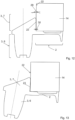
- FIG. 12 shows one spring holder 3 which is tiltable with relation to the isolating element 2.
- the drive unit 18 is not loaded so the extended part 7, namely its side 23, has a radial distance 30 to the lateral surface 22 of stator 14 (only a part of stator 14 is depicted here and in Fig. 13 ). So in this situation the end element 1, namely the isolating element 2, contacts the stator 14 only at its front end.
- stator core of stator 14 here is approximately 0.1 mm at the bottom of the extended part 7. This means that the radius of the circular arc of the side 23 is at least 0.1 mm larger than the radius of the stator 14. This radial distance 30 is needed to allow for mounting the end element 1 to the stator 14 and for tilting the extended part 7 radially inwards.
- side 23 and lateral surface 22 can be parallel to each other or they can be arranged in an angle to each other, as in Fig. 12 .
- This draft angle 29 should be smaller than the tilt angle.
- the side 23 is tilted radially outwards by a draft angle 29 of 0.5°. This means that the radius of the side 23 is growing with growing axial distance from the isolating element 2, i.e. in the direction vertically upwards. So the radial distance 30 between side 23 of extended part 7 and stator 14 is not constant along the axial direction, it increases starting from 0.1 mm at the bottom of extended part 7.
- the axis of the spring holder 3 is depicted as a dotted line and is vertical.
- the stator 14 is loaded, e.g. pressed downwards against the section of the isolating element 2 contacting the stator 14 on its end face.
- the spring holder 3 tilts inside from the first position to the second position so the side 23 of the extended part 7 touches the lateral surface 22 of stator 14 and thus embraces the stator 14 at its lateral side 22.
- the axis of the spring holder 3 is again depicted as a dotted line.
- the angle between the axis of the spring holder 3 and the vertical is the tilt angle.
- the spring holder 3, and its side 23, is tilted in the amount of the tilt angle against the vertical direction, i.e. against the first position of Fig. 12 .
- a typical tilt angle for small compressors would be 1.25°.
Landscapes
- Engineering & Computer Science (AREA)
- Mechanical Engineering (AREA)
- General Engineering & Computer Science (AREA)
- Power Engineering (AREA)
- Compressor (AREA)
Description
- The present invention relates to a refrigerant compressor comprising a hermetically sealed housing and a drive unit disposed in the interior of the housing, the drive unit comprising an electric motor with a stator, wherein an end element is mounted on the stator,
- whereas the end element comprises at least one isolating element which covers an axial end portion of the stator and isolates a stator core and stator windings,
- whereas the isolating element has a ring-like structure,
- whereas the end element comprises several spring holders,
- whereas each spring holder holds a spring which springs support the electric motor in a housing of the hermetically sealed refrigerant compressor,
- whereas the spring holders extend radially outside the isolating element,
- whereas the spring holders are oriented parallel to the axis of the isolating element and an insertion part of each spring holder extends in a first axial direction beyond the neighbouring area of the isolating element,
- whereas the spring holders and the isolating element are integral parts of the end element.
- The end element of the present invention is favourably used as a lower end element.
- The drive unit of a refrigerant compressor normally comprises a piston/cylinder unit for cyclical compression of a refrigerant, and an electric motor to drive the piston/cylinder unit. The electric motor comprises a stator and a rotor, whereas the rotor, especially an interior permanent magnet rotor, is situated inside the stator.
- A respective end element is known from
US 2009/0068030 A1 . To achieve the goal of simplifying the design of the spring mounting the end element (here called end plate) of the stator comprises at least one integrated first spring holder (here called spring retainer). According toUS 2009/0068030 A1 it is thus possible, particularly in connection with small compressors whose low refrigeration output only requires a small drive motor, to realise a relatively simply designed spring retainer, in which no additional threaded bores, screws, mounting fittings or the like are required. The spring retainers are made in one piece with the end plate of the stator. The end element is normally made of plastic. - The spring holders disclosed in
US 2009/0068030 A1 lie radially outside of the remaining ring-like end element. The stator normally is rigidly connected to the bearing of the shaft and to the piston/cylinder unit. The stator and accordingly the spring holders thus bear the whole weight of the drive unit and the spring holders also have to carry additional load, e.g. due to an acceleration when the compressor is transported within a vehicle, or during start and stop of the compressor. The spring holders transfer the load to spring members, normally helical springs, which spring members are mounted inside the compressor housing and which transfer the load to the compressor housing and/or mounting elements outside the compressor housing for mounting the compressor into a refrigerating unit. So the connection between a spring holder and the remaining end element has to bear not only the weight of the drive unit but also additional load. -
AT 9772 U1 AT 9772 U1 -
KR 2011 0089745 A KR 2011 0089745 A claim 1. - It is therefore an object of the invention to provide an end element which is apt to relieve the connection between spring holder and remaining end element from load and/or to give additional support to the spring holder in the loaded state.
- The invention relates to a refrigerant compressor according to
claim 1. - Tiltable here means that the spring holders can be tilted to a certain extent against the isolating element, i.e. until they touch the lateral surface of the stator in the operational state, and the mechanical connection between spring holder and isolating element does not break or get otherwise damaged. So the connection between spring holder and isolating element is an elastic connection. The tilt angle, until the extended part of the spring holder touches the lateral surface of the stator, can be in a range between 1° and 10°, for example between 1° and 5°, preferably between 1° and 3°, more preferably between 1° and 2°. The smaller the tilt angle, the smaller is the stress level in the end element, i.e. in the connection between spring holder and isolating element.
- The term "axial" here refers either to the axis of the stator, which axis in the operational state is the same as the axis of the rotor, i.e. the axis of rotation of the rotor, or it refers to the axis of the isolating element, which axis is the same as of the stator when the end element is mounted on the stator. The axis of the isolating element is the axis of mathematical rotation of the ring-like isolating element.
- That the isolating element is adapted to cover an axial end portion of the stator means that the isolating element is at least also situated at one axial end of the stator. It can cover the front end of the axial end portion and/or the outer lateral surface of the axial end portion and/or the inner lateral surface of the axial end portion. The isolating element can extend from the end portion further down the axial direction into the stator. The isolating element touches at least the front end of the axial end portion of the stator. The isolating element normally connects to the stator in a form-locking way.
- That the isolating element has a ring-like structure means that it has a central opening around its axis and that the isolating element can at least accommodate a cylindrical body inside, here the rotor.
- That the spring holders extend radially outside the isolating element means that their position as seen in radial direction is at least partially, normally completely, outside the isolating element. Especially the insertion part is normally completely outside the isolating element.
- The first axial direction is the direction parallel to the axis of the isolating element pointing in the direction away from the stator when referring to the mounted status of the end element. The second axial direction is the direction parallel to the axis of the isolating element pointing in the direction to the stator when referring to the mounted status of the end element. So first and second axial directions are anti-parallel.
- That the spring holders and the isolating element are integral parts of the end element means that the end element is one-part.
- Because the extended part of the spring holder can tilt radially inwards it can touch the lateral surface of the stator in the tilted state, so the lateral surface of the stator supports the extended part which reduces stress in the spring holder and in the connection between spring holder and the remaining end element, i.e. the isolating element. One extended part together with the isolating element in the loaded state act as a bracket to hold the stator in position, since the isolating element contacts the stator at its front end and the extended part contacts the stator at its lateral surface. So the end element helps centering the springs and holds the drive unit in position in lateral direction.
- One embodiment of the invention consists in that the spring holder includes a hollow body with at least one stiffening rib inside the hollow body extending from one side wall to the opposing side wall of the hollow body. Due to the hollow form the spring holder is strong and lightweight, and the stiffening rib adds stability.
- Preferably the stiffening rib extends radially, so the spring holder is especially stable when tilting radially inwards.
- One embodiment of the invention consists in that at the side facing the isolating element a cross section of the extended part has the form of a circular arc. The radius of the circular arc should correspond to the radius of the lateral surface of the stator. Since the lateral surface of the stator normally has a cylindrical form the extended part will contact the lateral surface along its surface and thus transfer load across the whole angular range of the circular arc. The angular range, measured with reference to the ring-like isolating element, can be between 10° and 40°, for example between 25° and 35°. In comparison thereto the angular range which is covered by one insertion part of a spring holder normally is one half to one third of the angular range of the circular arc of the extended part. So the angular range which is covered by one insertion part could be between 3° and 20°, for example around 10°.
- That the radius of the circular arc should correspond to the radius of the lateral surface of the stator does not mean that the radius should be the same since in that case it would not be possible to mount the end element to the stator or to tilt the extended part radially inwards.
- According to one embodiment of the invention the side of the extended part facing the isolating element is tilted radially outwards by a draft angle so that the radius of the side is growing with growing axial distance from the isolating element. This means that at the bottom of the extended part the radial distance to the stator will be smaller and thus keep the stator in position whereas at the top of the extended part the radial distance to the stator will be larger, allowing the extended part to tilt inwards and embrace the stator in case the refrigerant compressor is loaded. The draft angle should be smaller than the tilt angle, e.g. less than half of the tilt angle.
- To further enhance the effect of a large area of contact between extended part and the lateral surface of the stator, the extended part can broaden in the direction radially inwards. So the extended part is broader at the side facing the lateral surface of the stator than at the side facing radially outwards.
- One embodiment of the invention consists in that each spring holder is partially enclosed by a rim which extends to a web oriented normal to the axis of the isolating element and additionally connecting the spring holder in a symmetric manner to the isolating element. This helps to add stability when the spring holders are tilted since the area of connection between spring holder and isolating element is enlarged. There can be one continuous rim running round the whole circumference of the isolating element enclosing all spring holders. Or there can be a separate rim for each spring holder extending from the spring holder to the left and to the right on the isolating element and ending on the isolating element. When seen in axial direction, the rim can be positioned between insertion part and extended part.
- The present invention refers to a refrigerant compressor comprising a hermetically sealed housing and a drive unit disposed in the interior of the housing, the drive unit comprising an electric motor with a stator and an end element according to the invention,
- whereas the end element comprises at least one isolating element which covers an axial end portion of the stator and isolates the stator core and the stator windings,
- whereas each spring holder holds a spring which springs support the electric motor in the housing of the hermetically sealed refrigerant compressor,
- whereas the extended parts of the spring holders in a first position with relation to the stator, when the refrigerant compressor is not loaded, each have a radial distance to the lateral surface of the stator core, and
- whereas the extended part of at least one spring holder in a second position with relation to the stator, when the refrigerant compressor is loaded, contacts the lateral surface of the stator core due to a tilt radially inwards form the first position into the second position.
- In the unloaded state of the refrigerant compressor the springs and spring holders only have to carry the weight of the drive unit. In a loaded state of the refrigerant compressor the drive unit is moved with relation to the sealed housing. This can be due to the movement of the drive unit during start or stop of the electric motor, or due to an acceleration of the compressor itself, e.g. if it is mounted in a vehicle and the vehicle accelerates or brakes or goes over a bump. Such a load has vertical and horizontal components. Any vertical load component pressing the drive unit vertically down will result in the extended parts of the spring holders contacting the lateral surface of the stator. The spring holders then act as a bracket to hold the stator in its position inside the sealed housing.
- Additionally, the spring holders of the end element according to the invention prevent the springs from falling off the spring holders during transport or high start or stop loads of the compressor.
- According to one embodiment of the refrigerant compressor the tilt angle between first position and second position is in the range between 1° and 10°, preferably between 1° and 5°, more preferably between 1° and 3°.
- According to one embodiment of the refrigerant compressor in the first position the radial distance between extended part of a spring holder and lateral surface of the stator core is less than 1 mm, preferably less than 0.5 mm. The radial distance need not be constant. Since the present invention is best used for small compressors the radial distance must not be too wide in order to keep the position of the stator stabilized. Small compressors here particularly are understood as having a stator diameter of 40-100 mm and a housing diameter of 80-120 mm.
- So according to one embodiment of the refrigerant compressor in the first position the radial distance between the extended part of a spring holder and the lateral surface of the stator core is equal to or more than 0.1 mm.
- According to one embodiment of the refrigerant compressor in the first position the side of extended part facing the isolating element is tilted radially outwards by a draft angle so that the radius of the side is growing with growing axial distance from the isolating element.
- The invention will now be explained in greater detail using exemplary embodiments. The drawings are meant as examples and are supposed to present the idea of the invention, but by no means to restrict it or to reproduce it in final manner.
- In this regard, the figures show:
- Fig. 1
- the perspective view of an end element according to the invention,
- Fig. 2
- the side view of the end element of
Fig. 1 , - Fig. 3
- the top view of the end element of
Fig. 1 , - Fig. 4
- the bottom view of the end element of
Fig. 1 , - Fig. 5
- the perspective view of a stator with an end element of
Fig. 1 , - Fig. 6
- the side view of the stator of
Fig. 5 , - Fig. 7
- the top view of the stator of
Fig. 5 , - Fig. 8
- the bottom view of the stator of
Fig. 5 , - Fig. 9
- a longitudinal cross section of a refrigerant compressor with an end element of
Fig. 1 , the section plane including the axis of the stator but no spring holders, - Fig. 10
- a longitudinal cross section of a refrigerant compressor with an end element of
Fig. 1 , the section plane being parallel to the section plane ofFig. 9 , going through two spring holders, - Fig. 11
- a longitudinal cross section of a refrigerant compressor with an end element of
Fig. 1 , the section plane including the axis of the stator and two spring holders, - Fig. 12
- a longitudinal section through one spring holder in the unloaded state,
- Fig. 13
- a longitudinal section through one spring holder in the loaded state.
-
Fig. 1 shows anend element 1 comprising one isolatingelement 2 having a ring-like structure and fourspring holders 3. Thespring holders 3 are situated radially outside the isolatingelement 2. Theend element 1 is made of plastic as one part. Theend element 1 can be made as a plastic injection moulded part. Theend element 1 hasprotrusions 13 oriented radially inward which align theend element 1 to the stator core of stator 14 (forstator 14 see e.g.Fig. 9 ) and isolate stator core and stator windings. Eachspring holder 3 is mainly a hollow body with at least onestiffening rib 4 inside the hollow body extending from one side wall to the opposing side wall of the hollow body. The stiffeningrib 4 extends radially with relation to theaxis 5 of the isolatingelement 2, seeFig. 2 . - The
side 23 of theextended part 7 of thespring holder 3, seeFig. 2 , facing the isolatingelement 2 has a cross section in the form of a circular arc. - According to
Fig. 2 , thespring holders 3 are oriented parallel to theaxis 5 of the isolatingelement 2. Theinsertion part 6 of eachspring holder 3 extends in a firstaxial direction 8 beyond the neighbouring area of the isolatingelement 2, which firstaxial direction 8 is downwards here. Here the secondaxial direction 9, into which theextended part 7 extends, is upwards. Theinsertion part 6 can be inserted into ahelical spring 10, seeFig. 9 and10 . Here the stiffeningrib 4 extends through thewhole spring holder 3 in axial direction, that is from theextended part 7 down to the bottom ofinsertion part 6. - The
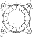
extended part 7 broadens in the direction radially inwards, which can be seen best inFig. 3 and4 . Eachspring holder 3 is partially enclosed by arim 11 which extends to aweb 12 oriented normal to theaxis 5 of the isolatingelement 2 and additionally connecting thespring holder 3 in a symmetric manner to the isolatingelement 2, that is,web 12 on one side of thespring holder 3 is symmetric to theweb 12 on the other side of thespring holder 3. The axis of symmetry would here contain thestiffening rib 4. Therim 11 separates thespring holder 3 ininsertion part 6 andextended part 7, seeFig. 2 . - In
Fig. 3 theangular range 26 of the circular arc of theside 23 of theextended part 7, measured with reference to the ring-like isolatingelement 2, i.e. with reference toaxis 5, here is about 29°. Theangular range 27 of theinsertion part 6 here is about 10°. -
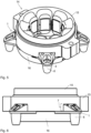
Fig. 5-8 show a stator with anend element 1 according to the invention mounted at one axial end portion of thestator 14, here at the lower end of the stator which is close to the bottom of the refrigerant compressor in the operational status. Thestator 14 has a stator core having several pole teeth on its radial inside, said pole teeth being formed by stator webs and salient poles on the inside of the stator opening. In grooves formed between the pole teeth, stator windings are located, each surrounding a stator web. Between the stator core and the stator windings is located an electrical isolation in the form of anupper end element 15 and a lower end element, whereas the lower end element is anend element 1 according to the invention. It is not excluded that additionally theupper end element 15 is made according to the invention. Eachend element end elements stator 14. Thus, the twoend elements end elements end elements stator 14. Theend elements - A
cover element 16 additionally covers theend element 1 at the bottom. It can be made of plastic and e.g. snapped ontoend element 1. Since the electrical connection between the coils of the stator windings of thestator 14 are placed on the outer diameter of theend element 1 thecover element 16 has the function to generate an isolation between theseconnection wires 28 and thehelical springs 10, seeFig. 11 . -
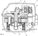
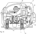
Fig. 9 ,10 and11 show a refrigerant compressor with a hermeticallyclosed housing 17, here comprising anupper housing part 24 which is welded to alower housing part 25. Via fourhelical springs 10 thedrive unit 18 is supported on thelower housing part 25 of thehousing 17, or rather on its bottom. Thedrive unit 18 comprises a piston/cylinder unit and the electric motor. The electric motor has astator 14 and arotor 19. Therotor 19 is unrotatably connected to a crankshaft 20 and rotates inside a central opening of thestator 14. Therotor 19 here is an IPM (internal permanent magnet) rotor. Theend element 1 is mounted on the lower axial end portion of thestator 14. - In the bottom of the refrigerant compressor
second spring holders 21 are located, on which thehelical springs 10 are mounted. Thesecond spring holders 21 comprise substantially cylindrical sections. Also theinsertion part 6 of thespring holder 3 has at least partially a cylindrical form for insertion into thehelical spring 10. The end of theinsertion part 6 of thespring holder 3 has at least partially an approximate frustoconical form. - In extreme vertical load situations the
insertion part 6 ofspring holder 3 contacts thesecond spring holder 21 which gives additional stability to thedrive unit 18. - In
Fig. 11 the section plane includes theaxis 5 of thestator 14 and two spring holders, which means that the section plane ofFig. 11 is turned by 45° with relation to the section plane ofFig. 9 . It can be seen inFig. 11 that thecover element 16 separatesconnection wires 28 from the helical springs 10. - In
Fig. 12 and 13 the actual displacement ofspring holder 3 has been increased by a factor of 30 to better show theend element 1 in its loaded and thus deformed shape.Fig. 12 shows onespring holder 3 which is tiltable with relation to the isolatingelement 2. InFig. 12 thedrive unit 18 is not loaded so theextended part 7, namely itsside 23, has aradial distance 30 to thelateral surface 22 of stator 14 (only a part ofstator 14 is depicted here and inFig. 13 ). So in this situation theend element 1, namely the isolatingelement 2, contacts thestator 14 only at its front end. Theradial distance 30 betweenextended part 7 ofspring holder 3, i.e. itsside 23, andlateral surface 22 of the stator core ofstator 14 here is approximately 0.1 mm at the bottom of theextended part 7. This means that the radius of the circular arc of theside 23 is at least 0.1 mm larger than the radius of thestator 14. Thisradial distance 30 is needed to allow for mounting theend element 1 to thestator 14 and for tilting theextended part 7 radially inwards. - Generally, in this unloaded first position,
side 23 andlateral surface 22 can be parallel to each other or they can be arranged in an angle to each other, as inFig. 12 . Thisdraft angle 29 should be smaller than the tilt angle. InFig. 12 theside 23 is tilted radially outwards by adraft angle 29 of 0.5°. This means that the radius of theside 23 is growing with growing axial distance from the isolatingelement 2, i.e. in the direction vertically upwards. So theradial distance 30 betweenside 23 ofextended part 7 andstator 14 is not constant along the axial direction, it increases starting from 0.1 mm at the bottom ofextended part 7. InFig. 12 the axis of thespring holder 3 is depicted as a dotted line and is vertical. - In
Fig. 13 thestator 14 is loaded, e.g. pressed downwards against the section of the isolatingelement 2 contacting thestator 14 on its end face. Thespring holder 3 tilts inside from the first position to the second position so theside 23 of theextended part 7 touches thelateral surface 22 ofstator 14 and thus embraces thestator 14 at itslateral side 22. The axis of thespring holder 3 is again depicted as a dotted line. The angle between the axis of thespring holder 3 and the vertical is the tilt angle. Thespring holder 3, and itsside 23, is tilted in the amount of the tilt angle against the vertical direction, i.e. against the first position ofFig. 12 . A typical tilt angle for small compressors would be 1.25°. -
- 1
- end element
- 2
- isolating element
- 3
- spring holder
- 4
- stiffening rib
- 5
- axis
- 6
- insertion part
- 7
- extended part
- 8
- first axial direction
- 9
- second axial direction
- 10
- helical spring
- 11
- rim
- 12
- web
- 13
- protrusions
- 14
- stator
- 15
- upper end element
- 16
- cover element
- 17
- housing
- 18
- drive unit
- 19
- rotor
- 20
- crank shaft
- 21
- second spring holder
- 22
- lateral surface
- 23
- side of
extended part 7 - 24
- upper housing part
- 25
- lower housing part
- 26
- angular range of the circular arc of
side 23 - 27
- angular range of the
insertion part 6 - 28
- connection wires
- 29
- draft angle
- 30
- radial distance
Claims (11)
- Refrigerant compressor comprising a hermetically sealed housing (17) and a drive unit (18) disposed in the interior of the housing, the drive unit (18) comprising an electric motor with a stator (14), wherein an end element (1) is mounted on the stator (14),- whereas the end element (1) comprises at least one isolating element (2) which covers an axial end portion of the stator (14) and isolates a stator core and stator windings,- whereas the isolating element (2) has a ring-like structure,- whereas the end element (1) comprises several spring holders (3),- whereas each spring holder (3) holds a spring (10) which springs support the electric motor in a housing (17) of the hermetically sealed refrigerant compressor,- whereas the spring holders (3) extend radially outside the isolating element (2),- whereas the spring holders (3) are oriented parallel to the axis (5) of the isolating element (2) and an insertion part (6) of each spring holder (3) extends in a first axial direction (8) beyond the neighbouring area of the isolating element (2),- whereas the spring holders (3) and the isolating element (2) are integral parts of the end element (1),- whereas the spring holders (3) are tiltable with relation to the isolating element (2) so that an extended part (7) of a spring holder, which extended part extends in a second axial direction (9) beyond the neighbouring area of the isolating element (2), can tilt radially inwards so that in the operational state of the end element (1) the extended part (7) of the spring holder (3) can contact a lateral surface (22) of the stator core,- whereas the extended parts (7) of the spring holders (3) in a first position with relation to the stator (14), when the refrigerant compressor is not loaded, each have a radial distance to the lateral surface (22) of the stator core, and- whereas the extended part (7) of at least one spring holder (3) in a second position with relation to the stator (14), when the refrigerant compressor is loaded, contacts the lateral surface (22) of the stator core due to a tilt radially inwards form the first position into the second position.
- Refrigerant compressor according to claim 1, characterized in that the tilt angle between first position and second position is in the range between 1° and 10°, preferably between 1° and 5°, more preferably between 1° and 3°.
- Refrigerant compressor according to claim 1 or 2, characterized in that in the first position the radial distance between extended part (7) of a spring holder (3) and lateral surface (22) of the stator core is less than 1 mm, preferably less than 0.5 mm.
- Refrigerant compressor according to any of claims 1 to 3, characterized in that in the first position the radial distance between the extended part (7) of a spring holder (3) and the lateral surface (22) of the stator core is equal to or more than 0.1 mm.
- Refrigerant compressor according to any of claims 1 to 4, characterized in that in the first position the side (23) of extended part (7) facing the isolating element (2) is tilted radially outwards by a draft angle (29) so that the radius of the side (23) is growing with growing axial distance from the isolating element (2).
- Refrigerant compressor according to any of claims 1 to 5, characterized in that the spring holder (3) includes a hollow body with at least one stiffening rib (4) inside the hollow body extending from one side wall to the opposing side wall of the hollow body.
- Refrigerant compressor according to claim 6, characterized in that the stiffening rib (4) extends radially.
- Refrigerant compressor according to any of claims 1 to 7, characterized in that at the side (23) facing the isolating element (2) a cross section of the extended part (7) has the form of a circular arc.
- Refrigerant compressor according to claim 8, characterized in that the angular range (26) of the circular arc, measured with reference to the ring-like isolating element (2), is between 10° and 40°, preferably between 25° and 35°.
- Refrigerant compressor according to any of claims 1 to 9, characterized in that the extended part (7) broadens in the direction radially inwards.
- Refrigerant compressor according to any of claims 1 to 10, characterized in that each spring holder (3) is partially enclosed by a rim (11) which extends to a web (12) oriented normal to the axis (5) of the isolating element (2) and additionally connects the spring holder (3) in a symmetric manner to the isolating element (2).
Priority Applications (3)
| Application Number | Priority Date | Filing Date | Title |
|---|---|---|---|
| EP19208869.8A EP3822486B1 (en) | 2019-11-13 | 2019-11-13 | End element for the stator of an electric motor of a hermetically sealed refrigerant compressor |
| US17/094,497 US11644038B2 (en) | 2019-11-13 | 2020-11-10 | End element for the stator of an electric motor of a hermetically sealed refrigerant compressor |
| CN202011267468.9A CN112803627B (en) | 2019-11-13 | 2020-11-13 | End element of a stator of an electric motor of a hermetically sealed refrigeration compressor |
Applications Claiming Priority (1)
| Application Number | Priority Date | Filing Date | Title |
|---|---|---|---|
| EP19208869.8A EP3822486B1 (en) | 2019-11-13 | 2019-11-13 | End element for the stator of an electric motor of a hermetically sealed refrigerant compressor |
Publications (2)
| Publication Number | Publication Date |
|---|---|
| EP3822486A1 EP3822486A1 (en) | 2021-05-19 |
| EP3822486B1 true EP3822486B1 (en) | 2023-06-07 |
Family
ID=68581413
Family Applications (1)
| Application Number | Title | Priority Date | Filing Date |
|---|---|---|---|
| EP19208869.8A Active EP3822486B1 (en) | 2019-11-13 | 2019-11-13 | End element for the stator of an electric motor of a hermetically sealed refrigerant compressor |
Country Status (3)
| Country | Link |
|---|---|
| US (1) | US11644038B2 (en) |
| EP (1) | EP3822486B1 (en) |
| CN (1) | CN112803627B (en) |
Families Citing this family (3)
| Publication number | Priority date | Publication date | Assignee | Title |
|---|---|---|---|---|
| KR20210156095A (en) * | 2020-06-17 | 2021-12-24 | 엘지전자 주식회사 | Linear compressor |
| US12616984B2 (en) * | 2023-10-16 | 2026-05-05 | Glorymakeup Inc. | Programmable air supply system with liquid cooling and noise suppression |
| US12486849B2 (en) | 2024-01-08 | 2025-12-02 | Flowserve Pte. Ltd. | Mechanism for reducing eddy current losses in sealless pumps and turbines having directly driven impellers |
Family Cites Families (14)
| Publication number | Priority date | Publication date | Assignee | Title |
|---|---|---|---|---|
| AT9772B (en) | 1900-07-30 | 1902-11-10 | Franz Dr Kress | Safety locking device for bicycles. |
| US3250461A (en) * | 1964-09-08 | 1966-05-10 | Lennox Ind Inc | Hermetic compressor assembly |
| US4108581A (en) * | 1976-07-26 | 1978-08-22 | Carrier Corporation | Suspension system for motor-compressor unit |
| US4601644A (en) * | 1984-11-13 | 1986-07-22 | Tecumseh Products Company | Main bearing for a rotary compressor |
| US5090657A (en) * | 1990-08-06 | 1992-02-25 | Tecumseh Products Company | Cable reinforced mounting system |
| US5435702A (en) * | 1993-01-28 | 1995-07-25 | Matsushita Refrigeration Company | Hermetic compressor |
| US5342179A (en) * | 1993-03-05 | 1994-08-30 | Tecumseh Products Company | Compressor shock absorbing mount assembly |
| AT9772U1 (en) * | 2007-01-19 | 2008-03-15 | Acc Austria Gmbh | REFRIGERANT COMPRESSOR |
| DE102007038443B4 (en) | 2007-08-16 | 2010-02-11 | Danfoss Compressors Gmbh | Hermetically sealed refrigerant compressor device |
| KR20110089745A (en) * | 2010-02-01 | 2011-08-09 | 엘지전자 주식회사 | Motor and compressor with same |
| JP2012205421A (en) * | 2011-03-25 | 2012-10-22 | Panasonic Corp | Motor, pump, and apparatus |
| FR2997807B1 (en) * | 2012-11-06 | 2016-10-21 | Valeo Equip Electr Moteur | SYNCHRONOUS ELECTRIC MOTOR WITH PERMANENT MAGNETS AND ELECTRIC COMPRESSOR COMPRISING SUCH AN ELECTRIC MOTOR |
| WO2017137328A1 (en) * | 2016-02-09 | 2017-08-17 | Arcelik Anonim Sirketi | A compressor that is operated in a silent manner |
| DE102016222614B4 (en) * | 2016-11-17 | 2024-06-06 | Robert Bosch Gmbh | Stator of an electrical machine, an electrical machine, and method for producing such a |
-
2019
- 2019-11-13 EP EP19208869.8A patent/EP3822486B1/en active Active
-
2020
- 2020-11-10 US US17/094,497 patent/US11644038B2/en active Active
- 2020-11-13 CN CN202011267468.9A patent/CN112803627B/en active Active
Also Published As
| Publication number | Publication date |
|---|---|
| CN112803627A (en) | 2021-05-14 |
| EP3822486A1 (en) | 2021-05-19 |
| CN112803627B (en) | 2023-11-28 |
| US11644038B2 (en) | 2023-05-09 |
| US20210140439A1 (en) | 2021-05-13 |
Similar Documents
| Publication | Publication Date | Title |
|---|---|---|
| US11644038B2 (en) | End element for the stator of an electric motor of a hermetically sealed refrigerant compressor | |
| CN101262161B (en) | Brushless motor and manufacturing method thereof | |
| AU2013364501B2 (en) | A motor | |
| KR102559314B1 (en) | Cluster assembly and Electric motor driven compressor with the same | |
| US9279474B2 (en) | Flywheel assembly | |
| US8113797B2 (en) | Hermetically enclosed refrigerant compressor arrangement | |
| US11742716B2 (en) | Motor | |
| US4964609A (en) | Compressor mounting apparatus | |
| US20090307717A1 (en) | Spindle Motor | |
| US4946351A (en) | Compressor mounting system | |
| US20190052132A1 (en) | Electric motor, in particular for fans for combustion air, or for an air/combustion gas mixture, in gas burners, stator assembly for such electric motor, and method of assembly for such stator assembly | |
| US20160208805A1 (en) | Centrifugal pump | |
| JP6879780B2 (en) | Small recoil wheel assembly | |
| KR20200042813A (en) | Hollow Shaft Motor | |
| US12180952B2 (en) | Hermetic compressor | |
| US20150061420A1 (en) | Motor | |
| US20110135523A1 (en) | Sealed compressor with motor standard spacer providing bearing mount | |
| US20070041855A1 (en) | Linear compressor, particularly refrigerant compressor | |
| US20010054854A1 (en) | Spindle motor for driving disc | |
| CN107165805B (en) | compressor | |
| US10224784B2 (en) | Motor | |
| CN102562527B (en) | Refrigerant compressor | |
| CN102725941B (en) | The outer body of an electromechanical energy converter | |
| KR20170108873A (en) | Electric motor and electric apparatus using same | |
| KR102796592B1 (en) | Exterior rotor Motor |
Legal Events
| Date | Code | Title | Description |
|---|---|---|---|
| PUAI | Public reference made under article 153(3) epc to a published international application that has entered the european phase |
Free format text: ORIGINAL CODE: 0009012 |
|
| STAA | Information on the status of an ep patent application or granted ep patent |
Free format text: STATUS: THE APPLICATION HAS BEEN PUBLISHED |
|
| AK | Designated contracting states |
Kind code of ref document: A1 Designated state(s): AL AT BE BG CH CY CZ DE DK EE ES FI FR GB GR HR HU IE IS IT LI LT LU LV MC MK MT NL NO PL PT RO RS SE SI SK SM TR |
|
| STAA | Information on the status of an ep patent application or granted ep patent |
Free format text: STATUS: REQUEST FOR EXAMINATION WAS MADE |
|
| 17P | Request for examination filed |
Effective date: 20211013 |
|
| RBV | Designated contracting states (corrected) |
Designated state(s): AL AT BE BG CH CY CZ DE DK EE ES FI FR GB GR HR HU IE IS IT LI LT LU LV MC MK MT NL NO PL PT RO RS SE SI SK SM TR |
|
| RAP3 | Party data changed (applicant data changed or rights of an application transferred) |
Owner name: SECOP GMBH |
|
| GRAP | Despatch of communication of intention to grant a patent |
Free format text: ORIGINAL CODE: EPIDOSNIGR1 |
|
| STAA | Information on the status of an ep patent application or granted ep patent |
Free format text: STATUS: GRANT OF PATENT IS INTENDED |
|
| INTG | Intention to grant announced |
Effective date: 20230103 |
|
| GRAS | Grant fee paid |
Free format text: ORIGINAL CODE: EPIDOSNIGR3 |
|
| GRAA | (expected) grant |
Free format text: ORIGINAL CODE: 0009210 |
|
| STAA | Information on the status of an ep patent application or granted ep patent |
Free format text: STATUS: THE PATENT HAS BEEN GRANTED |
|
| AK | Designated contracting states |
Kind code of ref document: B1 Designated state(s): AL AT BE BG CH CY CZ DE DK EE ES FI FR GB GR HR HU IE IS IT LI LT LU LV MC MK MT NL NO PL PT RO RS SE SI SK SM TR |
|
| REG | Reference to a national code |
Ref country code: GB Ref legal event code: FG4D |
|
| REG | Reference to a national code |
Ref country code: CH Ref legal event code: EP Ref country code: AT Ref legal event code: REF Ref document number: 1575830 Country of ref document: AT Kind code of ref document: T Effective date: 20230615 |
|
| REG | Reference to a national code |
Ref country code: DE Ref legal event code: R096 Ref document number: 602019029935 Country of ref document: DE |
|
| P01 | Opt-out of the competence of the unified patent court (upc) registered |
Effective date: 20230525 |
|
| REG | Reference to a national code |
Ref country code: SK Ref legal event code: T3 Ref document number: E 41827 Country of ref document: SK |
|
| REG | Reference to a national code |
Ref country code: LT Ref legal event code: MG9D |
|
| REG | Reference to a national code |
Ref country code: NL Ref legal event code: MP Effective date: 20230607 |
|
| PG25 | Lapsed in a contracting state [announced via postgrant information from national office to epo] |
Ref country code: SE Free format text: LAPSE BECAUSE OF FAILURE TO SUBMIT A TRANSLATION OF THE DESCRIPTION OR TO PAY THE FEE WITHIN THE PRESCRIBED TIME-LIMIT Effective date: 20230607 Ref country code: NO Free format text: LAPSE BECAUSE OF FAILURE TO SUBMIT A TRANSLATION OF THE DESCRIPTION OR TO PAY THE FEE WITHIN THE PRESCRIBED TIME-LIMIT Effective date: 20230907 Ref country code: ES Free format text: LAPSE BECAUSE OF FAILURE TO SUBMIT A TRANSLATION OF THE DESCRIPTION OR TO PAY THE FEE WITHIN THE PRESCRIBED TIME-LIMIT Effective date: 20230607 |
|
| PG25 | Lapsed in a contracting state [announced via postgrant information from national office to epo] |
Ref country code: RS Free format text: LAPSE BECAUSE OF FAILURE TO SUBMIT A TRANSLATION OF THE DESCRIPTION OR TO PAY THE FEE WITHIN THE PRESCRIBED TIME-LIMIT Effective date: 20230607 Ref country code: NL Free format text: LAPSE BECAUSE OF FAILURE TO SUBMIT A TRANSLATION OF THE DESCRIPTION OR TO PAY THE FEE WITHIN THE PRESCRIBED TIME-LIMIT Effective date: 20230607 Ref country code: LV Free format text: LAPSE BECAUSE OF FAILURE TO SUBMIT A TRANSLATION OF THE DESCRIPTION OR TO PAY THE FEE WITHIN THE PRESCRIBED TIME-LIMIT Effective date: 20230607 Ref country code: LT Free format text: LAPSE BECAUSE OF FAILURE TO SUBMIT A TRANSLATION OF THE DESCRIPTION OR TO PAY THE FEE WITHIN THE PRESCRIBED TIME-LIMIT Effective date: 20230607 Ref country code: HR Free format text: LAPSE BECAUSE OF FAILURE TO SUBMIT A TRANSLATION OF THE DESCRIPTION OR TO PAY THE FEE WITHIN THE PRESCRIBED TIME-LIMIT Effective date: 20230607 Ref country code: GR Free format text: LAPSE BECAUSE OF FAILURE TO SUBMIT A TRANSLATION OF THE DESCRIPTION OR TO PAY THE FEE WITHIN THE PRESCRIBED TIME-LIMIT Effective date: 20230908 |
|
| PG25 | Lapsed in a contracting state [announced via postgrant information from national office to epo] |
Ref country code: FI Free format text: LAPSE BECAUSE OF FAILURE TO SUBMIT A TRANSLATION OF THE DESCRIPTION OR TO PAY THE FEE WITHIN THE PRESCRIBED TIME-LIMIT Effective date: 20230607 |
|
| PG25 | Lapsed in a contracting state [announced via postgrant information from national office to epo] |
Ref country code: IS Free format text: LAPSE BECAUSE OF FAILURE TO SUBMIT A TRANSLATION OF THE DESCRIPTION OR TO PAY THE FEE WITHIN THE PRESCRIBED TIME-LIMIT Effective date: 20231007 |
|
| PG25 | Lapsed in a contracting state [announced via postgrant information from national office to epo] |
Ref country code: SM Free format text: LAPSE BECAUSE OF FAILURE TO SUBMIT A TRANSLATION OF THE DESCRIPTION OR TO PAY THE FEE WITHIN THE PRESCRIBED TIME-LIMIT Effective date: 20230607 Ref country code: RO Free format text: LAPSE BECAUSE OF FAILURE TO SUBMIT A TRANSLATION OF THE DESCRIPTION OR TO PAY THE FEE WITHIN THE PRESCRIBED TIME-LIMIT Effective date: 20230607 Ref country code: PT Free format text: LAPSE BECAUSE OF FAILURE TO SUBMIT A TRANSLATION OF THE DESCRIPTION OR TO PAY THE FEE WITHIN THE PRESCRIBED TIME-LIMIT Effective date: 20231009 Ref country code: IS Free format text: LAPSE BECAUSE OF FAILURE TO SUBMIT A TRANSLATION OF THE DESCRIPTION OR TO PAY THE FEE WITHIN THE PRESCRIBED TIME-LIMIT Effective date: 20231007 Ref country code: EE Free format text: LAPSE BECAUSE OF FAILURE TO SUBMIT A TRANSLATION OF THE DESCRIPTION OR TO PAY THE FEE WITHIN THE PRESCRIBED TIME-LIMIT Effective date: 20230607 Ref country code: CZ Free format text: LAPSE BECAUSE OF FAILURE TO SUBMIT A TRANSLATION OF THE DESCRIPTION OR TO PAY THE FEE WITHIN THE PRESCRIBED TIME-LIMIT Effective date: 20230607 |
|
| REG | Reference to a national code |
Ref country code: AT Ref legal event code: UEP Ref document number: 1575830 Country of ref document: AT Kind code of ref document: T Effective date: 20230607 |
|
| PG25 | Lapsed in a contracting state [announced via postgrant information from national office to epo] |
Ref country code: PL Free format text: LAPSE BECAUSE OF FAILURE TO SUBMIT A TRANSLATION OF THE DESCRIPTION OR TO PAY THE FEE WITHIN THE PRESCRIBED TIME-LIMIT Effective date: 20230607 |
|
| REG | Reference to a national code |
Ref country code: DE Ref legal event code: R097 Ref document number: 602019029935 Country of ref document: DE |
|
| PLBE | No opposition filed within time limit |
Free format text: ORIGINAL CODE: 0009261 |
|
| STAA | Information on the status of an ep patent application or granted ep patent |
Free format text: STATUS: NO OPPOSITION FILED WITHIN TIME LIMIT |
|
| PG25 | Lapsed in a contracting state [announced via postgrant information from national office to epo] |
Ref country code: DK Free format text: LAPSE BECAUSE OF FAILURE TO SUBMIT A TRANSLATION OF THE DESCRIPTION OR TO PAY THE FEE WITHIN THE PRESCRIBED TIME-LIMIT Effective date: 20230607 |
|
| PG25 | Lapsed in a contracting state [announced via postgrant information from national office to epo] |
Ref country code: SI Free format text: LAPSE BECAUSE OF FAILURE TO SUBMIT A TRANSLATION OF THE DESCRIPTION OR TO PAY THE FEE WITHIN THE PRESCRIBED TIME-LIMIT Effective date: 20230607 |
|
| 26N | No opposition filed |
Effective date: 20240308 |
|
| PG25 | Lapsed in a contracting state [announced via postgrant information from national office to epo] |
Ref country code: SI Free format text: LAPSE BECAUSE OF FAILURE TO SUBMIT A TRANSLATION OF THE DESCRIPTION OR TO PAY THE FEE WITHIN THE PRESCRIBED TIME-LIMIT Effective date: 20230607 |
|
| REG | Reference to a national code |
Ref country code: CH Ref legal event code: PL |
|
| PG25 | Lapsed in a contracting state [announced via postgrant information from national office to epo] |
Ref country code: MC Free format text: LAPSE BECAUSE OF FAILURE TO SUBMIT A TRANSLATION OF THE DESCRIPTION OR TO PAY THE FEE WITHIN THE PRESCRIBED TIME-LIMIT Effective date: 20230607 |
|
| PG25 | Lapsed in a contracting state [announced via postgrant information from national office to epo] |
Ref country code: LU Free format text: LAPSE BECAUSE OF NON-PAYMENT OF DUE FEES Effective date: 20231113 |
|
| PG25 | Lapsed in a contracting state [announced via postgrant information from national office to epo] |
Ref country code: CH Free format text: LAPSE BECAUSE OF NON-PAYMENT OF DUE FEES Effective date: 20231130 |
|
| GBPC | Gb: european patent ceased through non-payment of renewal fee |
Effective date: 20231113 |
|
| PG25 | Lapsed in a contracting state [announced via postgrant information from national office to epo] |
Ref country code: MC Free format text: LAPSE BECAUSE OF FAILURE TO SUBMIT A TRANSLATION OF THE DESCRIPTION OR TO PAY THE FEE WITHIN THE PRESCRIBED TIME-LIMIT Effective date: 20230607 Ref country code: LU Free format text: LAPSE BECAUSE OF NON-PAYMENT OF DUE FEES Effective date: 20231113 Ref country code: CH Free format text: LAPSE BECAUSE OF NON-PAYMENT OF DUE FEES Effective date: 20231130 |
|
| REG | Reference to a national code |
Ref country code: BE Ref legal event code: MM Effective date: 20231130 |
|
| REG | Reference to a national code |
Ref country code: IE Ref legal event code: MM4A |
|
| PG25 | Lapsed in a contracting state [announced via postgrant information from national office to epo] |
Ref country code: IE Free format text: LAPSE BECAUSE OF NON-PAYMENT OF DUE FEES Effective date: 20231113 |
|
| PG25 | Lapsed in a contracting state [announced via postgrant information from national office to epo] |
Ref country code: GB Free format text: LAPSE BECAUSE OF NON-PAYMENT OF DUE FEES Effective date: 20231113 |
|
| PG25 | Lapsed in a contracting state [announced via postgrant information from national office to epo] |
Ref country code: BE Free format text: LAPSE BECAUSE OF NON-PAYMENT OF DUE FEES Effective date: 20231130 |
|
| PG25 | Lapsed in a contracting state [announced via postgrant information from national office to epo] |
Ref country code: FR Free format text: LAPSE BECAUSE OF NON-PAYMENT OF DUE FEES Effective date: 20231130 |
|
| PG25 | Lapsed in a contracting state [announced via postgrant information from national office to epo] |
Ref country code: IE Free format text: LAPSE BECAUSE OF NON-PAYMENT OF DUE FEES Effective date: 20231113 Ref country code: GB Free format text: LAPSE BECAUSE OF NON-PAYMENT OF DUE FEES Effective date: 20231113 Ref country code: FR Free format text: LAPSE BECAUSE OF NON-PAYMENT OF DUE FEES Effective date: 20231130 Ref country code: BE Free format text: LAPSE BECAUSE OF NON-PAYMENT OF DUE FEES Effective date: 20231130 |
|
| PG25 | Lapsed in a contracting state [announced via postgrant information from national office to epo] |
Ref country code: BG Free format text: LAPSE BECAUSE OF FAILURE TO SUBMIT A TRANSLATION OF THE DESCRIPTION OR TO PAY THE FEE WITHIN THE PRESCRIBED TIME-LIMIT Effective date: 20230607 |
|
| PG25 | Lapsed in a contracting state [announced via postgrant information from national office to epo] |
Ref country code: BG Free format text: LAPSE BECAUSE OF FAILURE TO SUBMIT A TRANSLATION OF THE DESCRIPTION OR TO PAY THE FEE WITHIN THE PRESCRIBED TIME-LIMIT Effective date: 20230607 |
|
| PG25 | Lapsed in a contracting state [announced via postgrant information from national office to epo] |
Ref country code: CY Free format text: LAPSE BECAUSE OF FAILURE TO SUBMIT A TRANSLATION OF THE DESCRIPTION OR TO PAY THE FEE WITHIN THE PRESCRIBED TIME-LIMIT; INVALID AB INITIO Effective date: 20191113 |
|
| PG25 | Lapsed in a contracting state [announced via postgrant information from national office to epo] |
Ref country code: HU Free format text: LAPSE BECAUSE OF FAILURE TO SUBMIT A TRANSLATION OF THE DESCRIPTION OR TO PAY THE FEE WITHIN THE PRESCRIBED TIME-LIMIT; INVALID AB INITIO Effective date: 20191113 |
|
| PG25 | Lapsed in a contracting state [announced via postgrant information from national office to epo] |
Ref country code: TR Free format text: LAPSE BECAUSE OF FAILURE TO SUBMIT A TRANSLATION OF THE DESCRIPTION OR TO PAY THE FEE WITHIN THE PRESCRIBED TIME-LIMIT Effective date: 20230607 |
|
| PGFP | Annual fee paid to national office [announced via postgrant information from national office to epo] |
Ref country code: DE Payment date: 20251126 Year of fee payment: 7 |
|
| PGFP | Annual fee paid to national office [announced via postgrant information from national office to epo] |
Ref country code: AT Payment date: 20251126 Year of fee payment: 7 |
|
| PGFP | Annual fee paid to national office [announced via postgrant information from national office to epo] |
Ref country code: IT Payment date: 20251121 Year of fee payment: 7 |
|
| PGFP | Annual fee paid to national office [announced via postgrant information from national office to epo] |
Ref country code: SK Payment date: 20251027 Year of fee payment: 7 |