EP3822428B1 - Sandwich-structured composite panel - Google Patents
Sandwich-structured composite panel Download PDFInfo
- Publication number
- EP3822428B1 EP3822428B1 EP19209416.7A EP19209416A EP3822428B1 EP 3822428 B1 EP3822428 B1 EP 3822428B1 EP 19209416 A EP19209416 A EP 19209416A EP 3822428 B1 EP3822428 B1 EP 3822428B1
- Authority
- EP
- European Patent Office
- Prior art keywords
- composite panel
- panel
- skin
- attachment element
- face skin
- Prior art date
- Legal status (The legal status is an assumption and is not a legal conclusion. Google has not performed a legal analysis and makes no representation as to the accuracy of the status listed.)
- Active
Links
Images

Classifications
-
- E—FIXED CONSTRUCTIONS
- E04—BUILDING
- E04F—FINISHING WORK ON BUILDINGS, e.g. STAIRS, FLOORS
- E04F13/00—Coverings or linings, e.g. for walls or ceilings
- E04F13/07—Coverings or linings, e.g. for walls or ceilings composed of covering or lining elements; Sub-structures therefor; Fastening means therefor
- E04F13/08—Coverings or linings, e.g. for walls or ceilings composed of covering or lining elements; Sub-structures therefor; Fastening means therefor composed of a plurality of similar covering or lining elements
- E04F13/12—Coverings or linings, e.g. for walls or ceilings composed of covering or lining elements; Sub-structures therefor; Fastening means therefor composed of a plurality of similar covering or lining elements of metal or with an outer layer of metal or enameled metal
-
- E—FIXED CONSTRUCTIONS
- E04—BUILDING
- E04C—STRUCTURAL ELEMENTS; BUILDING MATERIALS
- E04C2/00—Building elements of relatively thin form for the construction of parts of buildings, e.g. sheet materials, slabs, or panels
- E04C2/02—Building elements of relatively thin form for the construction of parts of buildings, e.g. sheet materials, slabs, or panels characterised by specified materials
- E04C2/26—Building elements of relatively thin form for the construction of parts of buildings, e.g. sheet materials, slabs, or panels characterised by specified materials composed of materials covered by two or more of groups E04C2/04, E04C2/08, E04C2/10 or of materials covered by one of these groups with a material not specified in one of the groups
- E04C2/284—Building elements of relatively thin form for the construction of parts of buildings, e.g. sheet materials, slabs, or panels characterised by specified materials composed of materials covered by two or more of groups E04C2/04, E04C2/08, E04C2/10 or of materials covered by one of these groups with a material not specified in one of the groups at least one of the materials being insulating
-
- E—FIXED CONSTRUCTIONS
- E04—BUILDING
- E04C—STRUCTURAL ELEMENTS; BUILDING MATERIALS
- E04C2/00—Building elements of relatively thin form for the construction of parts of buildings, e.g. sheet materials, slabs, or panels
- E04C2/30—Building elements of relatively thin form for the construction of parts of buildings, e.g. sheet materials, slabs, or panels characterised by the shape or structure
- E04C2/34—Building elements of relatively thin form for the construction of parts of buildings, e.g. sheet materials, slabs, or panels characterised by the shape or structure composed of two or more spaced sheet-like parts
- E04C2/36—Building elements of relatively thin form for the construction of parts of buildings, e.g. sheet materials, slabs, or panels characterised by the shape or structure composed of two or more spaced sheet-like parts spaced apart by transversely-placed strip material, e.g. honeycomb panels
- E04C2/365—Building elements of relatively thin form for the construction of parts of buildings, e.g. sheet materials, slabs, or panels characterised by the shape or structure composed of two or more spaced sheet-like parts spaced apart by transversely-placed strip material, e.g. honeycomb panels by honeycomb structures
-
- E—FIXED CONSTRUCTIONS
- E04—BUILDING
- E04F—FINISHING WORK ON BUILDINGS, e.g. STAIRS, FLOORS
- E04F13/00—Coverings or linings, e.g. for walls or ceilings
- E04F13/07—Coverings or linings, e.g. for walls or ceilings composed of covering or lining elements; Sub-structures therefor; Fastening means therefor
- E04F13/08—Coverings or linings, e.g. for walls or ceilings composed of covering or lining elements; Sub-structures therefor; Fastening means therefor composed of a plurality of similar covering or lining elements
- E04F13/0801—Separate fastening elements
- E04F13/0803—Separate fastening elements with load-supporting elongated furring elements between wall and covering elements
- E04F13/081—Separate fastening elements with load-supporting elongated furring elements between wall and covering elements with additional fastening elements between furring elements and covering elements
- E04F13/0821—Separate fastening elements with load-supporting elongated furring elements between wall and covering elements with additional fastening elements between furring elements and covering elements the additional fastening elements located in-between two adjacent covering elements
- E04F13/0823—Separate fastening elements with load-supporting elongated furring elements between wall and covering elements with additional fastening elements between furring elements and covering elements the additional fastening elements located in-between two adjacent covering elements piercing the side faces of the covering elements
-
- E—FIXED CONSTRUCTIONS
- E04—BUILDING
- E04F—FINISHING WORK ON BUILDINGS, e.g. STAIRS, FLOORS
- E04F13/00—Coverings or linings, e.g. for walls or ceilings
- E04F13/07—Coverings or linings, e.g. for walls or ceilings composed of covering or lining elements; Sub-structures therefor; Fastening means therefor
- E04F13/08—Coverings or linings, e.g. for walls or ceilings composed of covering or lining elements; Sub-structures therefor; Fastening means therefor composed of a plurality of similar covering or lining elements
- E04F13/0801—Separate fastening elements
- E04F13/0832—Separate fastening elements without load-supporting elongated furring elements between wall and covering elements
- E04F13/0833—Separate fastening elements without load-supporting elongated furring elements between wall and covering elements not adjustable
- E04F13/0835—Separate fastening elements without load-supporting elongated furring elements between wall and covering elements not adjustable the fastening elements extending into the back side of the covering elements
-
- E—FIXED CONSTRUCTIONS
- E04—BUILDING
- E04F—FINISHING WORK ON BUILDINGS, e.g. STAIRS, FLOORS
- E04F13/00—Coverings or linings, e.g. for walls or ceilings
- E04F13/07—Coverings or linings, e.g. for walls or ceilings composed of covering or lining elements; Sub-structures therefor; Fastening means therefor
- E04F13/08—Coverings or linings, e.g. for walls or ceilings composed of covering or lining elements; Sub-structures therefor; Fastening means therefor composed of a plurality of similar covering or lining elements
- E04F13/0866—Coverings or linings, e.g. for walls or ceilings composed of covering or lining elements; Sub-structures therefor; Fastening means therefor composed of a plurality of similar covering or lining elements composed of several layers, e.g. sandwich panels or layered panels
Definitions
- the invention relates to a sandwich-structured composite panel.
- GB 2571396 discloses discloses a sandwich-structured composite panel that comprises a first face skin of sheet metal, a second face skin of sheet metal, providing the back surface of the panel, and a core arranged between the first face skin and the second face skin.
- AT 506954 discloses a wall or façade element composed of profile boards which are fastened to a substructure at a distance from one another by means of retaining clips.
- FR 1495776 discloses a building facade cladding which comprises suspension profiles having upwardly open retaining wings and cladding profile strips having connecting wings which can be inserted from above into the retaining wings.
- a sandwich-structured composite panel comprising a first face skin of sheet metal, providing the façade surface of the panel, a second face skin of sheet metal, providing the back surface of the panel, and a core arranged between the first face skin and the second face skin, the first and second face skins being attached to the core, an upper edge, comprising an upper edge skin construed from the sheet metal establishing the first face skin, a lower edge, comprising a lower edge skin construed from the sheet metal establishing the first face skin, an upper attachment element arranged in the upper edge, wherein the upper attachment element comprises a first fixing surface, the first fixing surface being attached to the second face skin of sheet metal, wherein the façade surface of the panel is arranged in a first angle in relation to the upper edge skin and the first fixing surface, the upper attachment element comprises an upper extension for attaching another composite panel above the composite panel, a lower attachment element arranged in the lower edge, said lower attachment element comprising a third fixing surface attached to the second face
- the composite panel according to the invention is characterised by what is stated in the independent claim. Some other embodiments are characterised by what is stated in the dependent claims. Inventive embodiments are also disclosed in the specification and drawings of this patent Features of the different embodiments of the invention may, within the scope of the basic inventive idea, be applied to other embodiments.
- the first angle is 91° - 150°.
- the first angle is 95° - 135°.
- the first angle is 100° - 115°.
- the upper attachment element comprises a second fixing surface attached to the second face skin in the upper edge, the second fixing surface being arranged in the first angle in relation to the first fixing surface.
- the upper attachment element comprises an attachment surface arranged parallel to the second face skin for fastening the composite panel to a support structure.
- the upper attachment element comprises an upper extension for attaching another composite panel above the composite panel.
- the composite panel comprises a lower attachment element arranged in the lower edge, said lower attachment element comprising a third fixing surface attached to the second face skin in the lower edge, wherein the façade surface of the panel is arranged in a second angle in relation to the lower edge skin and the third fixing surface, wherein the second angle is less than 90°.
- the lower attachment element comprises a fourth fixing surface attached to the second face skin and arranged in the second angle in relation to the third fixing surface.
- the second angle is selected so that the lower edge skin is at least substantially parallel with the upper edge skin.
- the attachment element is a profile, the length of which is about the width of the composite panel.
- the attachment element is an extruded aluminum profile.
- the face skin comprises aluminium.
- An advantage is that the skin is light.
- the face skin comprises at least one of the following materials: copper, brass, titanzink, steel, such as stainless steel.
- the core comprises a cell configuration.
- the cell configuration comprises aluminium.
- An advantage is that the core is light.
- the core comprises polymer material, such as polyethylene.
- polymer material such as polyethylene.
- the core is made of polymer, such as polyethylene, filled with at least one mineral filler.
- Figure 1 is a schematic side view of details of two composite panels in partial cross-section
- Figure 2 is a schematic side view of details of the two composite panels shown in Figure 1
- Figure 3 is another schematic side view of details of the two composite panels shown in Figure 1
- Figure 4 is another schematic side view of the two composite panels shown in Figure 1 .
- the sandwich-structured composite panel 100 may be used in building envelope, such as exterior walls and roofs of buildings.
- the panel 100 has typically a shape of quadrangle, such as quadrature or rectangle.
- the panel 100 comprises a first face skin 1 of sheet metal, providing the façade surface of the panel 100, a second face skin 2 of sheet metal, providing the back surface of the panel 100, and a core 5 that is arranged between the first face skin and the second face skin such that the first and second face skins 1, 2 are attached to the core 3.
- the face skin 1, 2 comprises aluminium. In some other embodiments, the face skin 1, 2 comprises at least one of the following materials: copper, brass, titanzink, steel, such as stainless steel. Typically, the first face skin 1 is made of same material as the second face skin 2, but not necessarily.
- the core 5 comprises a cell configuration, such as honeycomb structure.
- the material of the cell configuration may be e.g. aluminium or polymer.
- the core 5 comprises polymer material, e.g. polyolefin, such as polyethylene.
- the polymer material may be filled with at least one mineral filler.
- the material of the core 5 is at least substantially mineral material or ceramics.
- the panel 100 comprises an upper edge 3 that comprises an upper edge skin 6 construed from the sheet metal establishing the first face skin 1.
- the upper edge is made by cutting or milling a groove 17 in the second face skin 2 and the core 3, and then bending the panel 100 in a desired shape.
- the panel 100 further comprises a lower edge 4, comprising a lower edge skin 7 construed from the sheet metal establishing the first face skin 1, and preferably made as the upper edge 3.
- An upper attachment element 8 is arranged in the upper edge 3 of the panel.
- the upper attachment element 8 comprises a first 9 of said fixing surfaces is attached to the second face skin 2 in the upper edge 3.
- the first fixing surface 9 is in a first angle A, that is more than 90°, in relation to the façade surface of the panel 100.
- the upper attachment element 8 further comprises a second fixing surface 10 that is attached to the second face skin 2 behind of and thus parallel to the façade surface of the panel.
- the second fixing surface 10 is attached to the upper edge 3 by rivets 19. Additionally or alternatively, the attachment may be realized by screws, gluing etc. Additionally, the first fixing surface 9 may be attached to the panel by similar means.
- the first angle A is selected in range of 91° - 150°. In an embodiment, the first angle A is selected in range of 100° - 135°. In a still another embodiment, the first angle A is selected in range of 100° - 115°. In an embodiment, the first angle A is 105°.
- the upper attachment element 8 comprises an attachment surface 11 that is arranged parallel to the second face skin 2 for fastening the panel 100 to a support structure 12.
- the panel is fastened by screws 18, however another fastening means may also be used.
- the panel 100 comprises a lower attachment element 14 that is arranged in the lower edge 4.
- the lower attachment element 14 comprises a third fixing surface 15 attached to the lower edge 3 of the panel.
- the third fixing surface 15 is arranged in a second angle B in relation to the façade surface of the panel 100.
- the second angle B is less than 90°.
- the second angle B is selected so that the lower edge skin 7 is at least substantially parallel with the upper edge skin 6.
- the lower attachment element 14 comprises also a fourth fixing surface 16 that is attached to the second face skin 2.
- the fourth fixing surface 16 is arranged in the second angle B in relation to the third fixing surface 15.
- the upper attachment element 8 comprises an upper extension 13 for attaching another panel above the panel 100.
- the lower attachment element 14 comprises a groove-like counterpart 20 that receives the upper extension 13 of the panel arranged beneath.
- the groove-like shape allows the upper extension 13 to move therein, thus dimensional changes of the panels 100 caused by e.g. temperature variations do not cause stresses to the fastening of the panels.
- the structure of the attachment elements 8, 14 makes it also possible to adjust the width of the joint 23 between the panels. In an embodiment, the width of the joint 23 may be selected in range of 5 mm - 35 mm.
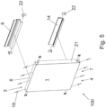
- Figure 5 is a schematic perspective view of a composite panel.
- the attachment element 8, 14 is a profile element, the length of which is about the width of the panel 100.
- At least one of the attachment elements 8, 14 comprises plurality of attachment elements arranged to the respective edge 3, 4 and spaced apart from each other.
- the attachment element 8, 14 is an extruded aluminum profile.
- At least one of side edges of the panel 100 may be provided with a side skin 21.
- the side skin 21 is construed from the first skin 1 that is bent in a desired shape.
- the side skin 21 is construed from a separate element that is attached to the structure of the panel 100.
- the side skins 21 are attached to the attachment element(s) 8, 14 by cover plates 22.
- the cover plates 22 are not fixed stationary to the attachment element (s) 8, 14, but they may move or glide in a slot 24 (best seen in Fig. 3 ) in direction of the profile. Thus, problems caused by thermal expansions may be eluded.
Landscapes
- Engineering & Computer Science (AREA)
- Architecture (AREA)
- Civil Engineering (AREA)
- Structural Engineering (AREA)
- Finishing Walls (AREA)
Description
- The invention relates to a sandwich-structured composite panel.
- It is known to use composite panels in buildings and constructions as a façade cladding panel element. Horizontal joints between the composite panels are susceptible to get dirty and retain moisture. This may cause the appearance of the joint or the whole façade to become untidy, and even reduce the life span of the composite panels.
-
GB 2571396 AT 506954 FR 1495776 - Viewed from a first aspect, there can be provided a sandwich-structured composite panel, comprising a first face skin of sheet metal, providing the façade surface of the panel, a second face skin of sheet metal, providing the back surface of the panel, and a core arranged between the first face skin and the second face skin, the first and second face skins being attached to the core, an upper edge, comprising an upper edge skin construed from the sheet metal establishing the first face skin, a lower edge, comprising a lower edge skin construed from the sheet metal establishing the first face skin, an upper attachment element arranged in the upper edge, wherein the upper attachment element comprises a first fixing surface, the first fixing surface being attached to the second face skin of sheet metal, wherein the façade surface of the panel is arranged in a first angle in relation to the upper edge skin and the first fixing surface, the upper attachment element comprises an upper extension for attaching another composite panel above the composite panel, a lower attachment element arranged in the lower edge, said lower attachment element comprising a third fixing surface attached to the second face skin in the lower edge, the façade surface of the panel is arranged in a second angle in relation to the lower edge skin and the third fixing surface, wherein said first angle is more than 90°, that the second angle is less than 90°, and that the lower attachment element comprises a groove-like counterpart arranged to receive the upper extension of the panel arranged beneath, wherein the groove-like shape allows the upper extension to move therein.
- Thereby a composite panel that reduces cumulation of dirt and moisture in the horizontal joint between the composite panels may be achieved.
- The composite panel according to the invention is characterised by what is stated in the independent claim. Some other embodiments are characterised by what is stated in the dependent claims. Inventive embodiments are also disclosed in the specification and drawings of this patent Features of the different embodiments of the invention may, within the scope of the basic inventive idea, be applied to other embodiments.
- In one embodiment, the first angle is 91° - 150°. An advantage is that cumulation of dirt and moisture may be effectively reduced.
- In one embodiment, the first angle is 95° - 135°. An advantage is that cumulation of dirt and moisture may be effectively reduced, and manufacturing of the panel is simple to realize.
- In one embodiment, the first angle is 100° - 115°. An advantage is that cumulation of dirt and moisture may be effectively reduced, and the appearance of the panel is close to rectangular prism.
- In one embodiment, the upper attachment element comprises a second fixing surface attached to the second face skin in the upper edge, the second fixing surface being arranged in the first angle in relation to the first fixing surface. An advantage is that a very stable structure of the composite panel may be achieved.
- In one embodiment, the upper attachment element comprises an attachment surface arranged parallel to the second face skin for fastening the composite panel to a support structure. An advantage is that the panel may be attached easily to the support structure.
- According to the invention, the upper attachment element comprises an upper extension for attaching another composite panel above the composite panel. An advantage is that a simple structure for attaching panels may be achieved.
- According to the invention, the composite panel comprises a lower attachment element arranged in the lower edge, said lower attachment element comprising a third fixing surface attached to the second face skin in the lower edge, wherein the façade surface of the panel is arranged in a second angle in relation to the lower edge skin and the third fixing surface, wherein the second angle is less than 90°. An advantage is that running of water behind the panel may be reduced or even prevented.
- In one embodiment, the lower attachment element comprises a fourth fixing surface attached to the second face skin and arranged in the second angle in relation to the third fixing surface. An advantage is that a very stable structure of the composite panel may be achieved.
- In one embodiment, the second angle is selected so that the lower edge skin is at least substantially parallel with the upper edge skin. An advantage is that a narrow joint between the panels may be created.
- In one embodiment, the attachment element is a profile, the length of which is about the width of the composite panel. An advantage is that a very good support for the panel may be achieved.
- In one embodiment, the attachment element is an extruded aluminum profile. An advantage is that precise attachment elements may be manufactured.
- In one embodiment, the face skin comprises aluminium.
- An advantage is that the skin is light.
- In one embodiment, the face skin comprises at least one of the following materials: copper, brass, titanzink, steel, such as stainless steel. An advantage is that the appearance of the skin may be customized.
- In one embodiment, the core comprises a cell configuration. An advantage is that the core and thus the panel may have a light but sturdy structure.
- In one embodiment, the cell configuration comprises aluminium. An advantage is that the core is light.
- In one embodiment, the core comprises polymer material, such as polyethylene. An advantage is that the core is light.
- In one embodiment, the core is made of polymer, such as polyethylene, filled with at least one mineral filler. An advantage is that a core being low-cost and having tailored properties regarding e.g. fire resistance may be achieved.
- Some embodiments illustrating the present disclosure are described in more detail in the attached drawings, in which
-
Figure 1 is a schematic side view of details of two composite panels in partial cross-section, -
Figure 2 is a schematic side view of details of the two composite panels shown inFigure 1 , -
Figure 3 is another schematic side view of details of the two composite panels shown inFigure 1 , -
Figure 4 is another schematic side view of the two composite panels shown inFigure 1 , and -
Figure 5 is a schematic perspective view of a composite panel. - In the figures, some embodiments are shown simplified for the sake of clarity. Similar parts are marked with the same reference numbers in the figures.
-
Figure 1 is a schematic side view of details of two composite panels in partial cross-section,Figure 2 is a schematic side view of details of the two composite panels shown inFigure 1, Figure 3 is another schematic side view of details of the two composite panels shown inFigure 1, and Figure 4 is another schematic side view of the two composite panels shown inFigure 1 . - The sandwich-structured composite panel 100 ("panel") may be used in building envelope, such as exterior walls and roofs of buildings. The
panel 100 has typically a shape of quadrangle, such as quadrature or rectangle. - The
panel 100 comprises afirst face skin 1 of sheet metal, providing the façade surface of thepanel 100, asecond face skin 2 of sheet metal, providing the back surface of thepanel 100, and acore 5 that is arranged between the first face skin and the second face skin such that the first andsecond face skins core 3. - In an embodiment, the
face skin face skin first face skin 1 is made of same material as thesecond face skin 2, but not necessarily. - In an embodiment, the
core 5 comprises a cell configuration, such as honeycomb structure. The material of the cell configuration may be e.g. aluminium or polymer. - In an embodiment, the
core 5 comprises polymer material, e.g. polyolefin, such as polyethylene. The polymer material may be filled with at least one mineral filler. In another embodiment, the material of thecore 5 is at least substantially mineral material or ceramics. - The
panel 100 comprises anupper edge 3 that comprises anupper edge skin 6 construed from the sheet metal establishing thefirst face skin 1. In an embodiment, the upper edge is made by cutting or milling agroove 17 in thesecond face skin 2 and thecore 3, and then bending thepanel 100 in a desired shape. - The
panel 100 further comprises alower edge 4, comprising alower edge skin 7 construed from the sheet metal establishing thefirst face skin 1, and preferably made as theupper edge 3. - An
upper attachment element 8 is arranged in theupper edge 3 of the panel. Theupper attachment element 8 comprises a first 9 of said fixing surfaces is attached to thesecond face skin 2 in theupper edge 3. Thefirst fixing surface 9 is in a first angle A, that is more than 90°, in relation to the façade surface of thepanel 100. - In an embodiment, the
upper attachment element 8 further comprises asecond fixing surface 10 that is attached to thesecond face skin 2 behind of and thus parallel to the façade surface of the panel. - In Figures, the
second fixing surface 10 is attached to theupper edge 3 byrivets 19. Additionally or alternatively, the attachment may be realized by screws, gluing etc. Additionally, thefirst fixing surface 9 may be attached to the panel by similar means. - In an embodiment, the first angle A is selected in range of 91° - 150°. In an embodiment, the first angle A is selected in range of 100° - 135°. In a still another embodiment, the first angle A is selected in range of 100° - 115°. In an embodiment, the first angle A is 105°.
- In an embodiment, the
upper attachment element 8 comprises anattachment surface 11 that is arranged parallel to thesecond face skin 2 for fastening thepanel 100 to asupport structure 12. In the embodiment shown in Figures, the panel is fastened byscrews 18, however another fastening means may also be used. - According to the invention, the
panel 100 comprises alower attachment element 14 that is arranged in thelower edge 4. Thelower attachment element 14 comprises athird fixing surface 15 attached to thelower edge 3 of the panel. - The
third fixing surface 15 is arranged in a second angle B in relation to the façade surface of thepanel 100. According to the invention, the second angle B is less than 90°. - In an embodiment, the second angle B is selected so that the
lower edge skin 7 is at least substantially parallel with theupper edge skin 6. - In an embodiment, the
lower attachment element 14 comprises also afourth fixing surface 16 that is attached to thesecond face skin 2. Thefourth fixing surface 16 is arranged in the second angle B in relation to the third fixingsurface 15. - According to the invention, the
upper attachment element 8 comprises anupper extension 13 for attaching another panel above thepanel 100. As shown in Figures, thelower attachment element 14 comprises a groove-like counterpart 20 that receives theupper extension 13 of the panel arranged beneath. The groove-like shape allows theupper extension 13 to move therein, thus dimensional changes of thepanels 100 caused by e.g. temperature variations do not cause stresses to the fastening of the panels. The structure of theattachment elements -
Figure 5 is a schematic perspective view of a composite panel. - In an embodiment, for instance as shown in
Figure 5 , theattachment element panel 100. - In another embodiment, at least one of the
attachment elements respective edge - In an embodiment, the
attachment element - At least one of side edges of the
panel 100 may be provided with aside skin 21. In an embodiment, theside skin 21 is construed from thefirst skin 1 that is bent in a desired shape. In another embodiment, theside skin 21 is construed from a separate element that is attached to the structure of thepanel 100. - In an embodiment, the side skins 21 are attached to the attachment element(s) 8, 14 by
cover plates 22. In an embodiment, thecover plates 22 are not fixed stationary to the attachment element (s) 8, 14, but they may move or glide in a slot 24 (best seen inFig. 3 ) in direction of the profile. Thus, problems caused by thermal expansions may be eluded. - The invention is not limited solely to the embodiments described above, but instead many variations are possible within the scope of the inventive concept defined by the claims below. Within the scope of the inventive concept the attributes of different embodiments and applications can be used in conjunction with or replace the attributes of another embodiment or application.
- The drawings and the related description are only intended to illustrate the idea of the invention. The invention may vary in detail within the scope of the invention as defined in the following claims.
-
- 1
- first face skin
- 2
- second face skin
- 3
- upper edge
- 4
- lower edge
- 5
- core
- 6
- upper edge skin
- 7
- lower edge skin
- 8
- upper attachment element
- 9
- first fixing surface
- 10
- second fixing surface
- 11
- attachment surface
- 12
- support structure
- 13
- upper extension
- 14
- lower attachment element
- 15
- third fixing surface
- 16
- fourth fixing surface
- 17
- groove
- 18
- screw
- 19
- rivet
- 20
- counterpart
- 21
- side skin
- 22
- cover plate
- 23
- joint
- 24
- slot
- 100
- composite panel
- A
- first angle
- B
- second angle
Claims (13)
- A sandwich-structured composite panel (100), comprising- a first face skin (1) of sheet metal, providing the façade surface of the panel (100),- a second face skin (2) of sheet metal, providing the back surface of the panel (100), and- a core (5) arranged between the first face skin and the second face skin, the first and second face skins being attached to the core,- an upper edge (3), comprising an upper edge skin (6) construed from the sheet metal establishing the first face skin (1),- a lower edge (4), comprising a lower edge skin (7) construed from the sheet metal establishing the first face skin (1),- an upper attachment element (8) arranged in the upper edge (3), wherein- the upper attachment element (8) comprises a first fixing surface (9),- the first fixing surface (9) being attached to the second face skin (2) of sheet metal, wherein- the façade surface of the panel (100) is arranged in a first angle (A) in relation to the upper edge skin (6) and the first fixing surface (9),- the upper attachment element (8) comprises an upper extension (13) for attaching another composite panel (100) above the composite panel (100),- a lower attachment element (14) is arranged in the lower edge (4), said lower attachment element (14) comprising- a third fixing surface (15) attached to the second face skin (2) in the lower edge (3), and- the façade surface of the panel (100) is arranged in a second angle (B) in relation to the lower edge skin (7) and the third fixing surface (15)characterized in that- said first angle (A) is more than 90°, that- the second angle (B) is less than 90°, and that- the lower attachment element (14) comprises a groove-like counterpart (20) arranged in use to receive the upper extension (13) of an identical panel arranged beneath, wherein- the groove-like shape allows the upper extension to move therein.
- The composite panel as claimed in claim 1, wherein the first angle (A) is 91° - 150°, preferably 95° - 135°, more preferably 100° - 115°.
- The composite panel as claimed in claim 1 or 2, wherein the upper attachment element (8) comprises an attachment surface (11) arranged parallel to the second face skin (2) for fastening the composite panel (100) to a support structure (12).
- The composite panel as claimed in any of the preceding claims, wherein the upper attachment element (8) comprises a second fixing surface (10) attached to the second face skin (2) in the upper edge (3), the second fixing surface (10) being arranged in the first angle (A) in relation to the first fixing surface (9).
- The composite panel as claimed in any of the preceding claims, wherein the lower attachment element (14) comprises a fourth fixing surface (16) attached to the second face skin and arranged in the second angle (B) in relation to the third fixing surface (15).
- The composite panel as claimed in any of the preceding claims, wherein the second angle (B) is selected so that the lower edge skin (7) is at least substantially parallel with the upper edge skin (6).
- The composite panel as claimed in any of the preceding claims, wherein the attachment element (8, 14) is a profile, the length of which is about the width of the composite panel (100).
- The composite panel as claimed in any of the preceding claims, wherein the attachment element (8, 14) is an extruded aluminum profile.
- The composite panel as claimed in any of the preceding claims, wherein the face skin (1, 2) comprises aluminium.
- The composite panel as claimed in any of the preceding claims, wherein the face skin (1, 2) comprises at least one of the following materials: copper, brass, titanzink, steel, such as stainless steel.
- The composite panel as claimed in any of the preceding claims, wherein the core (5) comprises a cell configuration.
- The composite panel as claimed in claim 9, wherein the cell configuration comprises aluminium.
- The composite panel as claimed in any of the preceding claims, wherein the core (5) comprises polymer material, such as polyethylene, optionally filled with at least one mineral filler.
Priority Applications (2)
| Application Number | Priority Date | Filing Date | Title |
|---|---|---|---|
| PL19209416.7T PL3822428T3 (en) | 2019-11-15 | 2019-11-15 | Sandwich-structured composite panel |
| EP19209416.7A EP3822428B1 (en) | 2019-11-15 | 2019-11-15 | Sandwich-structured composite panel |
Applications Claiming Priority (1)
| Application Number | Priority Date | Filing Date | Title |
|---|---|---|---|
| EP19209416.7A EP3822428B1 (en) | 2019-11-15 | 2019-11-15 | Sandwich-structured composite panel |
Publications (3)
| Publication Number | Publication Date |
|---|---|
| EP3822428A1 EP3822428A1 (en) | 2021-05-19 |
| EP3822428C0 EP3822428C0 (en) | 2023-06-07 |
| EP3822428B1 true EP3822428B1 (en) | 2023-06-07 |
Family
ID=68583175
Family Applications (1)
| Application Number | Title | Priority Date | Filing Date |
|---|---|---|---|
| EP19209416.7A Active EP3822428B1 (en) | 2019-11-15 | 2019-11-15 | Sandwich-structured composite panel |
Country Status (2)
| Country | Link |
|---|---|
| EP (1) | EP3822428B1 (en) |
| PL (1) | PL3822428T3 (en) |
Families Citing this family (2)
| Publication number | Priority date | Publication date | Assignee | Title |
|---|---|---|---|---|
| EP4134500A1 (en) * | 2021-08-12 | 2023-02-15 | SFS Group International AG | Facade fastening system with profile elements |
| WO2025093122A1 (en) * | 2023-11-02 | 2025-05-08 | Pelican | Cover panel and method for manufacturing same |
Citations (3)
| Publication number | Priority date | Publication date | Assignee | Title |
|---|---|---|---|---|
| US20070022682A1 (en) * | 2005-07-29 | 2007-02-01 | Engineered Extension Systems Llc | Panel wall system |
| GB2498327A (en) * | 2011-10-19 | 2013-07-17 | Simpson Strong Tie Co Inc | Fastening member |
| EP2930286A2 (en) * | 2014-04-11 | 2015-10-14 | Steffen Weiser | Façade system |
Family Cites Families (3)
| Publication number | Priority date | Publication date | Assignee | Title |
|---|---|---|---|---|
| FR1495776A (en) * | 1967-12-20 | |||
| AT506954B1 (en) * | 2008-12-12 | 2010-01-15 | Wolfgang Hutter | WALL OR FAÇADE ELEMENTS FROM PROFILE BOARDS |
| AU2018219979A1 (en) * | 2018-02-26 | 2019-09-12 | Fairview Architectural Pty Limited | A cladding for application to a structure and an assembly of the cladding with the structure |
-
2019
- 2019-11-15 PL PL19209416.7T patent/PL3822428T3/en unknown
- 2019-11-15 EP EP19209416.7A patent/EP3822428B1/en active Active
Patent Citations (3)
| Publication number | Priority date | Publication date | Assignee | Title |
|---|---|---|---|---|
| US20070022682A1 (en) * | 2005-07-29 | 2007-02-01 | Engineered Extension Systems Llc | Panel wall system |
| GB2498327A (en) * | 2011-10-19 | 2013-07-17 | Simpson Strong Tie Co Inc | Fastening member |
| EP2930286A2 (en) * | 2014-04-11 | 2015-10-14 | Steffen Weiser | Façade system |
Also Published As
| Publication number | Publication date |
|---|---|
| PL3822428T3 (en) | 2023-07-31 |
| EP3822428C0 (en) | 2023-06-07 |
| EP3822428A1 (en) | 2021-05-19 |
Similar Documents
| Publication | Publication Date | Title |
|---|---|---|
| US6314701B1 (en) | Construction panel and method | |
| US6792727B2 (en) | Curved wall panel system | |
| RU2719865C2 (en) | Ceiling installation system and corresponding method | |
| EP2556200B1 (en) | Open web grid runner | |
| US3080022A (en) | Wall construction | |
| GB2085046A (en) | Framing system for demountable walls | |
| EP3612688B1 (en) | Self-spacing lap siding product | |
| EP3822428A1 (en) | Sandwich-structured composite panel | |
| EP0327261A1 (en) | Building panels | |
| US10982431B2 (en) | Drainage channel for use in a building wall | |
| EP2395169B1 (en) | Drywall and cladding construction system | |
| RU2641140C1 (en) | Hinge system of lining of buildings and premises, including for building partitions | |
| JP6688012B2 (en) | Roof structure | |
| US4640076A (en) | Assembly system with clip for installing marble panels | |
| CZ194899A3 (en) | Laminated structural element | |
| RU81510U1 (en) | COMPOSITE PANEL WITH CELLULAR FILLER (OPTIONS) | |
| EP3868969B1 (en) | Fireproof wall | |
| EP4134496A1 (en) | Fireproof wall | |
| CN113463797B (en) | Pin-connected panel cuts off structure | |
| CN215977904U (en) | Pin-connected panel cuts off structure | |
| CA1043980A (en) | Connecting element | |
| WO2021245443A1 (en) | Building envelope | |
| JP2007100493A (en) | Structural materials for buildings and building structures | |
| EP4506521A1 (en) | System for obtaining a dry or mechanical building envelope or a cladding of building walls as well as building with cladded wall and method therefore | |
| RU95005U1 (en) | CONSTRUCTION OF WALLS FROM THREE-LAYER PANELS WITH FILLER FROM POLYURETHANE |
Legal Events
| Date | Code | Title | Description |
|---|---|---|---|
| PUAI | Public reference made under article 153(3) epc to a published international application that has entered the european phase |
Free format text: ORIGINAL CODE: 0009012 |
|
| STAA | Information on the status of an ep patent application or granted ep patent |
Free format text: STATUS: THE APPLICATION HAS BEEN PUBLISHED |
|
| AK | Designated contracting states |
Kind code of ref document: A1 Designated state(s): AL AT BE BG CH CY CZ DE DK EE ES FI FR GB GR HR HU IE IS IT LI LT LU LV MC MK MT NL NO PL PT RO RS SE SI SK SM TR |
|
| STAA | Information on the status of an ep patent application or granted ep patent |
Free format text: STATUS: REQUEST FOR EXAMINATION WAS MADE |
|
| 17P | Request for examination filed |
Effective date: 20210602 |
|
| RBV | Designated contracting states (corrected) |
Designated state(s): AL AT BE BG CH CY CZ DE DK EE ES FI FR GB GR HR HU IE IS IT LI LT LU LV MC MK MT NL NO PL PT RO RS SE SI SK SM TR |
|
| STAA | Information on the status of an ep patent application or granted ep patent |
Free format text: STATUS: EXAMINATION IS IN PROGRESS |
|
| 17Q | First examination report despatched |
Effective date: 20220721 |
|
| GRAP | Despatch of communication of intention to grant a patent |
Free format text: ORIGINAL CODE: EPIDOSNIGR1 |
|
| STAA | Information on the status of an ep patent application or granted ep patent |
Free format text: STATUS: GRANT OF PATENT IS INTENDED |
|
| RIC1 | Information provided on ipc code assigned before grant |
Ipc: E04C 2/284 19950101ALI20230110BHEP Ipc: E04F 13/08 19680901ALI20230110BHEP Ipc: E04C 2/36 19680901ALI20230110BHEP Ipc: E04F 13/12 19680901AFI20230110BHEP |
|
| INTG | Intention to grant announced |
Effective date: 20230130 |
|
| GRAS | Grant fee paid |
Free format text: ORIGINAL CODE: EPIDOSNIGR3 |
|
| GRAA | (expected) grant |
Free format text: ORIGINAL CODE: 0009210 |
|
| STAA | Information on the status of an ep patent application or granted ep patent |
Free format text: STATUS: THE PATENT HAS BEEN GRANTED |
|
| AK | Designated contracting states |
Kind code of ref document: B1 Designated state(s): AL AT BE BG CH CY CZ DE DK EE ES FI FR GB GR HR HU IE IS IT LI LT LU LV MC MK MT NL NO PL PT RO RS SE SI SK SM TR |
|
| REG | Reference to a national code |
Ref country code: GB Ref legal event code: FG4D |
|
| REG | Reference to a national code |
Ref country code: CH Ref legal event code: EP Ref country code: AT Ref legal event code: REF Ref document number: 1575487 Country of ref document: AT Kind code of ref document: T Effective date: 20230615 |
|
| REG | Reference to a national code |
Ref country code: DE Ref legal event code: R096 Ref document number: 602019029938 Country of ref document: DE |
|
| U01 | Request for unitary effect filed |
Effective date: 20230612 |
|
| U07 | Unitary effect registered |
Designated state(s): AT BE BG DE DK EE FI FR IT LT LU LV MT NL PT SE SI Effective date: 20230620 |
|
| REG | Reference to a national code |
Ref country code: LT Ref legal event code: MG9D |
|
| REG | Reference to a national code |
Ref country code: NO Ref legal event code: T2 Effective date: 20230607 |
|
| REG | Reference to a national code |
Ref country code: SK Ref legal event code: T3 Ref document number: E 42004 Country of ref document: SK |
|
| PG25 | Lapsed in a contracting state [announced via postgrant information from national office to epo] |
Ref country code: ES Free format text: LAPSE BECAUSE OF FAILURE TO SUBMIT A TRANSLATION OF THE DESCRIPTION OR TO PAY THE FEE WITHIN THE PRESCRIBED TIME-LIMIT Effective date: 20230607 |
|
| PG25 | Lapsed in a contracting state [announced via postgrant information from national office to epo] |
Ref country code: RS Free format text: LAPSE BECAUSE OF FAILURE TO SUBMIT A TRANSLATION OF THE DESCRIPTION OR TO PAY THE FEE WITHIN THE PRESCRIBED TIME-LIMIT Effective date: 20230607 Ref country code: HR Free format text: LAPSE BECAUSE OF FAILURE TO SUBMIT A TRANSLATION OF THE DESCRIPTION OR TO PAY THE FEE WITHIN THE PRESCRIBED TIME-LIMIT Effective date: 20230607 Ref country code: GR Free format text: LAPSE BECAUSE OF FAILURE TO SUBMIT A TRANSLATION OF THE DESCRIPTION OR TO PAY THE FEE WITHIN THE PRESCRIBED TIME-LIMIT Effective date: 20230908 |
|
| U20 | Renewal fee for the european patent with unitary effect paid |
Year of fee payment: 5 Effective date: 20231115 |
|
| PG25 | Lapsed in a contracting state [announced via postgrant information from national office to epo] |
Ref country code: IS Free format text: LAPSE BECAUSE OF FAILURE TO SUBMIT A TRANSLATION OF THE DESCRIPTION OR TO PAY THE FEE WITHIN THE PRESCRIBED TIME-LIMIT Effective date: 20231007 |
|
| PG25 | Lapsed in a contracting state [announced via postgrant information from national office to epo] |
Ref country code: SM Free format text: LAPSE BECAUSE OF FAILURE TO SUBMIT A TRANSLATION OF THE DESCRIPTION OR TO PAY THE FEE WITHIN THE PRESCRIBED TIME-LIMIT Effective date: 20230607 Ref country code: RO Free format text: LAPSE BECAUSE OF FAILURE TO SUBMIT A TRANSLATION OF THE DESCRIPTION OR TO PAY THE FEE WITHIN THE PRESCRIBED TIME-LIMIT Effective date: 20230607 Ref country code: IS Free format text: LAPSE BECAUSE OF FAILURE TO SUBMIT A TRANSLATION OF THE DESCRIPTION OR TO PAY THE FEE WITHIN THE PRESCRIBED TIME-LIMIT Effective date: 20231007 |
|
| REG | Reference to a national code |
Ref country code: DE Ref legal event code: R097 Ref document number: 602019029938 Country of ref document: DE |
|
| PLBE | No opposition filed within time limit |
Free format text: ORIGINAL CODE: 0009261 |
|
| STAA | Information on the status of an ep patent application or granted ep patent |
Free format text: STATUS: NO OPPOSITION FILED WITHIN TIME LIMIT |
|
| 26N | No opposition filed |
Effective date: 20240308 |
|
| REG | Reference to a national code |
Ref country code: CH Ref legal event code: PL |
|
| PG25 | Lapsed in a contracting state [announced via postgrant information from national office to epo] |
Ref country code: MC Free format text: LAPSE BECAUSE OF FAILURE TO SUBMIT A TRANSLATION OF THE DESCRIPTION OR TO PAY THE FEE WITHIN THE PRESCRIBED TIME-LIMIT Effective date: 20230607 |
|
| PG25 | Lapsed in a contracting state [announced via postgrant information from national office to epo] |
Ref country code: CH Free format text: LAPSE BECAUSE OF NON-PAYMENT OF DUE FEES Effective date: 20231130 |
|
| GBPC | Gb: european patent ceased through non-payment of renewal fee |
Effective date: 20231115 |
|
| PG25 | Lapsed in a contracting state [announced via postgrant information from national office to epo] |
Ref country code: MC Free format text: LAPSE BECAUSE OF FAILURE TO SUBMIT A TRANSLATION OF THE DESCRIPTION OR TO PAY THE FEE WITHIN THE PRESCRIBED TIME-LIMIT Effective date: 20230607 Ref country code: CH Free format text: LAPSE BECAUSE OF NON-PAYMENT OF DUE FEES Effective date: 20231130 |
|
| REG | Reference to a national code |
Ref country code: IE Ref legal event code: MM4A |
|
| PG25 | Lapsed in a contracting state [announced via postgrant information from national office to epo] |
Ref country code: IE Free format text: LAPSE BECAUSE OF NON-PAYMENT OF DUE FEES Effective date: 20231115 |
|
| PG25 | Lapsed in a contracting state [announced via postgrant information from national office to epo] |
Ref country code: GB Free format text: LAPSE BECAUSE OF NON-PAYMENT OF DUE FEES Effective date: 20231115 |
|
| PG25 | Lapsed in a contracting state [announced via postgrant information from national office to epo] |
Ref country code: IE Free format text: LAPSE BECAUSE OF NON-PAYMENT OF DUE FEES Effective date: 20231115 Ref country code: GB Free format text: LAPSE BECAUSE OF NON-PAYMENT OF DUE FEES Effective date: 20231115 |
|
| U20 | Renewal fee for the european patent with unitary effect paid |
Year of fee payment: 6 Effective date: 20241115 |
|
| PG25 | Lapsed in a contracting state [announced via postgrant information from national office to epo] |
Ref country code: CY Free format text: LAPSE BECAUSE OF FAILURE TO SUBMIT A TRANSLATION OF THE DESCRIPTION OR TO PAY THE FEE WITHIN THE PRESCRIBED TIME-LIMIT; INVALID AB INITIO Effective date: 20191115 |
|
| PG25 | Lapsed in a contracting state [announced via postgrant information from national office to epo] |
Ref country code: HU Free format text: LAPSE BECAUSE OF FAILURE TO SUBMIT A TRANSLATION OF THE DESCRIPTION OR TO PAY THE FEE WITHIN THE PRESCRIBED TIME-LIMIT; INVALID AB INITIO Effective date: 20191115 |
|
| PG25 | Lapsed in a contracting state [announced via postgrant information from national office to epo] |
Ref country code: TR Free format text: LAPSE BECAUSE OF FAILURE TO SUBMIT A TRANSLATION OF THE DESCRIPTION OR TO PAY THE FEE WITHIN THE PRESCRIBED TIME-LIMIT Effective date: 20230607 |
|
| U20 | Renewal fee for the european patent with unitary effect paid |
Year of fee payment: 7 Effective date: 20251117 |
|
| PGFP | Annual fee paid to national office [announced via postgrant information from national office to epo] |
Ref country code: NO Payment date: 20251120 Year of fee payment: 7 |
|
| PGFP | Annual fee paid to national office [announced via postgrant information from national office to epo] |
Ref country code: CZ Payment date: 20251024 Year of fee payment: 7 |
|
| PGFP | Annual fee paid to national office [announced via postgrant information from national office to epo] |
Ref country code: PL Payment date: 20251024 Year of fee payment: 7 |
|
| PGFP | Annual fee paid to national office [announced via postgrant information from national office to epo] |
Ref country code: SK Payment date: 20251103 Year of fee payment: 7 |