EP3822373A1 - Method for producing steel plate member - Google Patents
Method for producing steel plate member Download PDFInfo
- Publication number
- EP3822373A1 EP3822373A1 EP20198340.0A EP20198340A EP3822373A1 EP 3822373 A1 EP3822373 A1 EP 3822373A1 EP 20198340 A EP20198340 A EP 20198340A EP 3822373 A1 EP3822373 A1 EP 3822373A1
- Authority
- EP
- European Patent Office
- Prior art keywords
- region
- steel plate
- plate member
- temperature
- cooling rate
- Prior art date
- Legal status (The legal status is an assumption and is not a legal conclusion. Google has not performed a legal analysis and makes no representation as to the accuracy of the status listed.)
- Granted
Links
Images






Classifications
-
- C—CHEMISTRY; METALLURGY
- C21—METALLURGY OF IRON
- C21D—MODIFYING THE PHYSICAL STRUCTURE OF FERROUS METALS; GENERAL DEVICES FOR HEAT TREATMENT OF FERROUS OR NON-FERROUS METALS OR ALLOYS; MAKING METAL MALLEABLE, e.g. BY DECARBURISATION OR TEMPERING
- C21D9/00—Heat treatment, e.g. annealing, hardening, quenching or tempering, adapted for particular articles; Furnaces therefor
- C21D9/46—Heat treatment, e.g. annealing, hardening, quenching or tempering, adapted for particular articles; Furnaces therefor for sheet metals
-
- B—PERFORMING OPERATIONS; TRANSPORTING
- B21—MECHANICAL METAL-WORKING WITHOUT ESSENTIALLY REMOVING MATERIAL; PUNCHING METAL
- B21C—MANUFACTURE OF METAL SHEETS, WIRE, RODS, TUBES, PROFILES OR LIKE SEMI-MANUFACTURED PRODUCTS OTHERWISE THAN BY ROLLING; AUXILIARY OPERATIONS USED IN CONNECTION WITH METAL-WORKING WITHOUT ESSENTIALLY REMOVING MATERIAL
- B21C37/00—Manufacture of metal sheets, rods, wire, tubes, profiles or like semi-manufactured products, not otherwise provided for; Manufacture of tubes of special shape
- B21C37/02—Manufacture of metal sheets, rods, wire, tubes, profiles or like semi-manufactured products, not otherwise provided for; Manufacture of tubes of special shape of sheets
-
- C—CHEMISTRY; METALLURGY
- C21—METALLURGY OF IRON
- C21D—MODIFYING THE PHYSICAL STRUCTURE OF FERROUS METALS; GENERAL DEVICES FOR HEAT TREATMENT OF FERROUS OR NON-FERROUS METALS OR ALLOYS; MAKING METAL MALLEABLE, e.g. BY DECARBURISATION OR TEMPERING
- C21D1/00—General methods or devices for heat treatment, e.g. annealing, hardening, quenching or tempering
- C21D1/62—Quenching devices
- C21D1/673—Quenching devices for die quenching
-
- B—PERFORMING OPERATIONS; TRANSPORTING
- B21—MECHANICAL METAL-WORKING WITHOUT ESSENTIALLY REMOVING MATERIAL; PUNCHING METAL
- B21D—WORKING OR PROCESSING OF SHEET METAL OR METAL TUBES, RODS OR PROFILES WITHOUT ESSENTIALLY REMOVING MATERIAL; PUNCHING METAL
- B21D1/00—Straightening, restoring form or removing local distortions of sheet metal or specific articles made therefrom; Stretching sheet metal combined with rolling
- B21D1/06—Removing local distortions
- B21D1/10—Removing local distortions of specific articles made from sheet metal, e.g. mudguards
-
- B—PERFORMING OPERATIONS; TRANSPORTING
- B21—MECHANICAL METAL-WORKING WITHOUT ESSENTIALLY REMOVING MATERIAL; PUNCHING METAL
- B21D—WORKING OR PROCESSING OF SHEET METAL OR METAL TUBES, RODS OR PROFILES WITHOUT ESSENTIALLY REMOVING MATERIAL; PUNCHING METAL
- B21D1/00—Straightening, restoring form or removing local distortions of sheet metal or specific articles made therefrom; Stretching sheet metal combined with rolling
- B21D1/12—Straightening vehicle body parts or bodies
-
- B—PERFORMING OPERATIONS; TRANSPORTING
- B21—MECHANICAL METAL-WORKING WITHOUT ESSENTIALLY REMOVING MATERIAL; PUNCHING METAL
- B21D—WORKING OR PROCESSING OF SHEET METAL OR METAL TUBES, RODS OR PROFILES WITHOUT ESSENTIALLY REMOVING MATERIAL; PUNCHING METAL
- B21D22/00—Shaping without cutting, by stamping, spinning, or deep-drawing
- B21D22/02—Stamping using rigid devices or tools
- B21D22/022—Stamping using rigid devices or tools by heating the blank or stamping associated with heat treatment
-
- C—CHEMISTRY; METALLURGY
- C21—METALLURGY OF IRON
- C21D—MODIFYING THE PHYSICAL STRUCTURE OF FERROUS METALS; GENERAL DEVICES FOR HEAT TREATMENT OF FERROUS OR NON-FERROUS METALS OR ALLOYS; MAKING METAL MALLEABLE, e.g. BY DECARBURISATION OR TEMPERING
- C21D1/00—General methods or devices for heat treatment, e.g. annealing, hardening, quenching or tempering
- C21D1/18—Hardening; Quenching with or without subsequent tempering
-
- C—CHEMISTRY; METALLURGY
- C21—METALLURGY OF IRON
- C21D—MODIFYING THE PHYSICAL STRUCTURE OF FERROUS METALS; GENERAL DEVICES FOR HEAT TREATMENT OF FERROUS OR NON-FERROUS METALS OR ALLOYS; MAKING METAL MALLEABLE, e.g. BY DECARBURISATION OR TEMPERING
- C21D1/00—General methods or devices for heat treatment, e.g. annealing, hardening, quenching or tempering
- C21D1/26—Methods of annealing
-
- C—CHEMISTRY; METALLURGY
- C21—METALLURGY OF IRON
- C21D—MODIFYING THE PHYSICAL STRUCTURE OF FERROUS METALS; GENERAL DEVICES FOR HEAT TREATMENT OF FERROUS OR NON-FERROUS METALS OR ALLOYS; MAKING METAL MALLEABLE, e.g. BY DECARBURISATION OR TEMPERING
- C21D1/00—General methods or devices for heat treatment, e.g. annealing, hardening, quenching or tempering
- C21D1/34—Methods of heating
- C21D1/42—Induction heating
-
- C—CHEMISTRY; METALLURGY
- C21—METALLURGY OF IRON
- C21D—MODIFYING THE PHYSICAL STRUCTURE OF FERROUS METALS; GENERAL DEVICES FOR HEAT TREATMENT OF FERROUS OR NON-FERROUS METALS OR ALLOYS; MAKING METAL MALLEABLE, e.g. BY DECARBURISATION OR TEMPERING
- C21D1/00—General methods or devices for heat treatment, e.g. annealing, hardening, quenching or tempering
- C21D1/84—Controlled slow cooling
-
- C—CHEMISTRY; METALLURGY
- C21—METALLURGY OF IRON
- C21D—MODIFYING THE PHYSICAL STRUCTURE OF FERROUS METALS; GENERAL DEVICES FOR HEAT TREATMENT OF FERROUS OR NON-FERROUS METALS OR ALLOYS; MAKING METAL MALLEABLE, e.g. BY DECARBURISATION OR TEMPERING
- C21D8/00—Modifying the physical properties of ferrous metals or ferrous alloys by deformation combined with, or followed by, heat treatment
-
- C—CHEMISTRY; METALLURGY
- C21—METALLURGY OF IRON
- C21D—MODIFYING THE PHYSICAL STRUCTURE OF FERROUS METALS; GENERAL DEVICES FOR HEAT TREATMENT OF FERROUS OR NON-FERROUS METALS OR ALLOYS; MAKING METAL MALLEABLE, e.g. BY DECARBURISATION OR TEMPERING
- C21D8/00—Modifying the physical properties of ferrous metals or ferrous alloys by deformation combined with, or followed by, heat treatment
- C21D8/02—Modifying the physical properties of ferrous metals or ferrous alloys by deformation combined with, or followed by, heat treatment during manufacturing of plates or strips
- C21D8/0294—Modifying the physical properties of ferrous metals or ferrous alloys by deformation combined with, or followed by, heat treatment during manufacturing of plates or strips involving a localised treatment
-
- C—CHEMISTRY; METALLURGY
- C21—METALLURGY OF IRON
- C21D—MODIFYING THE PHYSICAL STRUCTURE OF FERROUS METALS; GENERAL DEVICES FOR HEAT TREATMENT OF FERROUS OR NON-FERROUS METALS OR ALLOYS; MAKING METAL MALLEABLE, e.g. BY DECARBURISATION OR TEMPERING
- C21D9/00—Heat treatment, e.g. annealing, hardening, quenching or tempering, adapted for particular articles; Furnaces therefor
- C21D9/0068—Heat treatment, e.g. annealing, hardening, quenching or tempering, adapted for particular articles; Furnaces therefor for particular articles not mentioned below
-
- C—CHEMISTRY; METALLURGY
- C21—METALLURGY OF IRON
- C21D—MODIFYING THE PHYSICAL STRUCTURE OF FERROUS METALS; GENERAL DEVICES FOR HEAT TREATMENT OF FERROUS OR NON-FERROUS METALS OR ALLOYS; MAKING METAL MALLEABLE, e.g. BY DECARBURISATION OR TEMPERING
- C21D2211/00—Microstructure comprising significant phases
- C21D2211/005—Ferrite
-
- C—CHEMISTRY; METALLURGY
- C21—METALLURGY OF IRON
- C21D—MODIFYING THE PHYSICAL STRUCTURE OF FERROUS METALS; GENERAL DEVICES FOR HEAT TREATMENT OF FERROUS OR NON-FERROUS METALS OR ALLOYS; MAKING METAL MALLEABLE, e.g. BY DECARBURISATION OR TEMPERING
- C21D2211/00—Microstructure comprising significant phases
- C21D2211/008—Martensite
-
- C—CHEMISTRY; METALLURGY
- C21—METALLURGY OF IRON
- C21D—MODIFYING THE PHYSICAL STRUCTURE OF FERROUS METALS; GENERAL DEVICES FOR HEAT TREATMENT OF FERROUS OR NON-FERROUS METALS OR ALLOYS; MAKING METAL MALLEABLE, e.g. BY DECARBURISATION OR TEMPERING
- C21D2211/00—Microstructure comprising significant phases
- C21D2211/009—Pearlite
-
- C—CHEMISTRY; METALLURGY
- C21—METALLURGY OF IRON
- C21D—MODIFYING THE PHYSICAL STRUCTURE OF FERROUS METALS; GENERAL DEVICES FOR HEAT TREATMENT OF FERROUS OR NON-FERROUS METALS OR ALLOYS; MAKING METAL MALLEABLE, e.g. BY DECARBURISATION OR TEMPERING
- C21D2221/00—Treating localised areas of an article
-
- C—CHEMISTRY; METALLURGY
- C21—METALLURGY OF IRON
- C21D—MODIFYING THE PHYSICAL STRUCTURE OF FERROUS METALS; GENERAL DEVICES FOR HEAT TREATMENT OF FERROUS OR NON-FERROUS METALS OR ALLOYS; MAKING METAL MALLEABLE, e.g. BY DECARBURISATION OR TEMPERING
- C21D2221/00—Treating localised areas of an article
- C21D2221/02—Edge parts
-
- Y—GENERAL TAGGING OF NEW TECHNOLOGICAL DEVELOPMENTS; GENERAL TAGGING OF CROSS-SECTIONAL TECHNOLOGIES SPANNING OVER SEVERAL SECTIONS OF THE IPC; TECHNICAL SUBJECTS COVERED BY FORMER USPC CROSS-REFERENCE ART COLLECTIONS [XRACs] AND DIGESTS
- Y02—TECHNOLOGIES OR APPLICATIONS FOR MITIGATION OR ADAPTATION AGAINST CLIMATE CHANGE
- Y02P—CLIMATE CHANGE MITIGATION TECHNOLOGIES IN THE PRODUCTION OR PROCESSING OF GOODS
- Y02P10/00—Technologies related to metal processing
- Y02P10/25—Process efficiency
Definitions
- the present disclosure relates to a method for producing a steel plate member, and in particular, to a method for producing a steel plate member including a hard region containing martensite and a soft region containing ferrite and pearlite.
- steel plate members including a hard region resistant to an impact and a soft region for absorbing an impact have been developed, for example, as structural members for automobiles.
- the present inventors have developed a method of forming a hard region and a soft region in one member by reheating a part of a steel plate member that has been quenched to a temperature between an austenite transformation start temperature A1 and an austenite transformation finish temperature A3 for tempering.
- an unstable microstructure containing martensite which is hard and further containing ferrite and pearlite which are soft is not formed in a boundary region of the soft region and the hard region, in consequence of which a fracture in the boundary region can be prevented.
- the present inventors have found the following problem regarding the method for producing the steel plate member including the hard region and the soft region.
- An object of the present disclosure is to provide a method for producing a steel plate member capable of suppressing degradation in the accuracy of the dimensions in a steel plate member including a hard region and a soft region.
- a method for producing a steel plate member according to one aspect of the present disclosure includes:
- the shape of the second region is corrected in a temperature range from a temperature that is equal to or lower than the austenite transformation start temperature A1 to a temperature that is equal to or higher than a temperature at which transformation into ferrite and pearlite is finished while maintaining the cooling rate slower than the lower critical cooling rate.
- the shape of the second region is corrected in the temperature range from a temperature that is equal to or lower than the austenite transformation start temperature A1 to a temperature that is equal to or higher than the temperature at which transformation into ferrite and pearlite is finished while maintaining a cooling rate slower than the lower critical cooling rate. Since the transformation superplastic phenomenon appears in accordance with the transformation from austenite to ferrite/pearlite, the shape of the second region of the steel plate member can be easily corrected with a small amount of power and the accuracy of the dimensions in the steel plate member is improved.
- the second region may be locally pressed by a correcting die having a pressing surface provided with a plurality of pins.
- the second region may be pressed by a correcting die including a heating mechanism therein.
- the second region may be pressed by a correcting die having at least a pressing surface made of a heat insulating material.
- the shape of the second region of the steel plate member can be corrected while maintaining a cooling rate slower than the lower critical cooling rate.
- the second region may be reheated to a temperature between the austenite transformation start temperature A1 and the austenite transformation finish temperature A3. Compared to the case in which the second region is reheated to a temperature equal to or higher than the austenite transformation finish temperature A3, the energy efficiency becomes higher and the strength in the second region is improved.
- the second region may be reheated by induction heating.
- the second region of the steel plate member may be rapidly heated.
- the method for producing the steel plate member according to the first embodiment is suitable as a method for producing a steel plate member including a hard region resistant to an impact and a soft region for absorbing an impact, the steel plate member being for use, for example, in automobiles.
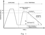
- Fig. 1 is a temperature chart showing the method for producing the steel plate member according to the first embodiment.
- the horizontal axis represents time (s) and the vertical axis represents temperature (°C).
- the method for producing the steel plate member according to the first embodiment includes a quenching step and a local tempering step. In the method for producing the steel plate member according to the first embodiment, the quenching step is performed first and then the local tempering step is performed.
- the entire steel plate member is heated to a temperature higher than an austenite transformation finish temperature A3.
- the microstructure of the entire steel plate member converts from ferrite and pearlite to an austenite single phase.
- the steel plate member is cooled at a cooling rate higher than an upper critical cooling rate.
- austenite is transformed into martensite and the microstructure of the entire steel plate member is converted to martensite which is hard.
- the steel plate member may be simply cooled after it is heated. Alternatively, the steel plate member may be cooled while being press formed. Since this press-forming is hot press forming, a high-strength steel plate member can be obtained by performing quenching at the time of the press forming while avoiding the springback that occurs during cold press forming.
- This hot press forming is typically called hot stamping.
- the steel plate used for hot stamping is, for example, but not limited to, a steel plate made of manganese-boron steel having a thickness of about 1-4 mm.
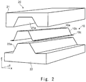
- Fig. 2 is a perspective view showing an example of a hot press forming apparatus.
- a hot press forming apparatus 20 includes an upper die 21 and a lower die 22, which are both dies.
- a heated steel plate which has, for example, a flat shape, is sandwiched between the upper die 21 and the lower die 22, and cooled while being press formed, and thus quenched.
- the steel plate member 10 after press forming shown in Fig. 2 has a hat-shaped cross section including a top plate 10a, side walls 10b, and flange parts 10c extending in a y-axis direction.
- the pair of side walls 10b are formed downward from end parts of the top plate 10a in a width direction (x-axis direction) extending in the y-axis direction. Further, each of the flange parts 10c projects outward from a lower end part (z-axis negative direction side) of the corresponding side wall 10b.
- a recess 21a that is recessed in a trapezoidal cross section is provided on a lower surface of the upper die 21 so as to extend in an axial direction (y-axis direction).
- a projection 22a having a trapezoidal cross section is provided on an upper surface of the lower die 22 so as to extend in the axial direction (y-axis direction).
- Fig. 2 shows a state in which the upper die 21 and the lower die 22 are separated from each other after press-forming the steel plate member 10.
- a z-axis positive direction is vertically upward and an xy plane is a horizontal plane.
- a part of the region of the steel plate member is reheated and softened. Specifically, as shown in Fig. 1 , a first region 11 of the steel plate member is not reheated and only a second region 12 of the steel plate member is reheated to a temperature higher than the austenite transformation start temperature A1.
- the heating temperature in the local tempering step according to the first embodiment is higher than the normal tempering temperature.
- FIG. 3 is a schematic perspective view of an induction heating apparatus for reheating the second region 12 of the steel plate member 10 in the local tempering step.
- an induction heating apparatus 30 is a high-frequency induction heating apparatus including a coil 31 and a high-frequency power supply 32.
- the coil 31 is a horizontally-positioned plate member having a U-shaped cross section so as to cover the entire upper and lower surfaces of the steel plate member 10 in the width direction (x-axis direction). As shown in Fig. 3 , the coil 31 is provided with irregularities that correspond to those of the steel plate member 10 having a hat-shaped cross section. Then the high-frequency power supply 32 is connected to respective ends of the coil 31.
- the shape of the coil 31 shown in Fig. 3 is merely one example and may be split, for example, into a plurality of parts.
- the second region 12 of the steel plate member 10 is inserted inside the coil 31 and is heated to a temperature higher than the austenite transformation start temperature A1 by induction heating.
- the second region 12 of the steel plate member 10 is reheated to, but not limited to, a temperature lower than the austenite transformation finish temperature A3 as shown in, for example, Fig. 1 .
- the boundary region between the first region 11 and the second region 12 is heated to a temperature lower than the austenite transformation start temperature A1 by heat conduction from the second region 12 and is thermally affected.
- the boundary region is a region that is heated to a temperature lower than the austenite transformation start temperature A1 and is thermally affected.
- the heating efficiency abruptly drops at the Curie point where the steel plate member 10 loses the magnetic properties, and thus the increase in the temperature of the heated region becomes difficult around the Curie point.
- austenite is non-magnetic while martensite, ferrite, and pearlite are ferromagnetic
- the Curie point lies between the austenite transformation start temperature A1 and the austenite transformation finish temperature A3.
- the steel plate member is cooled at a cooling rate slower than the lower critical cooling rate so as not to cause martensite transformation of the second region 12.
- the steel plate member may be rapidly cooled. Since the time for producing the steel plate member is reduced by rapid cooling, the production efficiency can be improved.
- Fig. 1 schematically shows a martensite transformation start temperature Ms, a martensite transformation finish temperature Mf, and a ferrite/pearlite nose in a Continuous Cooling Transformation (CCT) phase diagram. That is, Fig. 1 schematically shows the process in which the second region 12 having been reheated to a temperature between the austenite transformation start temperature A1 and the austenite transformation finish temperature A3 is cooled at a cooling rate slower than the lower critical cooling rate.
- CCT Continuous Cooling Transformation
- FIG. 4 is a schematic plan view showing the change in the microstructures of the steel plate member in the local tempering step when only the second region 12 of the steel plate member 10 is reheated to a temperature between the austenite transformation start temperature A1 and the austenite transformation finish temperature A3.
- the microstructure of the steel plate member 10 which has been subjected to the quenching step but has yet to be subjected to the local tempering step shown in the left part of Fig. 4 will be described.
- the entire microstructure of the steel plate member 10 before the local tempering step i.e., after the quenching step
- the martensite M is converted to tempered martensite TM and a part of the tempered martensite TM is further converted to austenite A in the second region 12. That is, the microstructure of the second region 12 becomes a mixed structure of the tempered martensite TM and the austenite A. Since the temperature of the heated second region 12 is close to the austenite transformation start temperature A1 in the vicinity of the boundary region in the second region 12, the amount of the austenite A decreases while the amount of the tempered martensite TM increases.
- the tempered martensite TM is used herein to collectively refer to all structures resulting from the reheating-induced softening of the martensite M and encompasses troostite and sorbite.
- the first region 11 of the steel plate member 10 is not reheated and thus is not thermally affected.
- the microstructure of the first region 11 therefore remains unchanged from the martensite M.
- the boundary region between the first region 11 and the second region 12 is heated to a temperature lower than the austenite transformation start temperature A1 by heat conduction from the second region 12 and thermally affected. This converts the microstructure of the boundary region from the martensite M to the tempered martensite TM.
- the temperature of the boundary region becomes higher and closer to the austenite transformation start temperature A1 with decreasing distance from the second region 12.
- the microstructure on the side of the second region 12 of the boundary region which is a major portion of the boundary region, is consisting of only the tempered martensite TM.
- both the tempered martensite TM and the martensite M are present. With decreasing distance from the first region 11 which is consisting of only the martensite M, the amount of the tempered martensite TM decreases and the amount of the martensite M increases.
- the boundary region becomes softer gradually in the direction from the first region 11 which is hard to the second region 12 which is soft.
- the microstructure of the steel plate member 10 which has been subjected to the local tempering step shown in the right part of Fig. 4 will be described.
- the cooling process in the local tempering step cools the steel plate member 10 at a cooling rate slower than the lower critical cooling rate.
- the austenite A in the second region 12 that has appeared during the heating is converted to ferrite and pearlite (ferrite/pearlite) FP.
- the microstructure of the second region 12 becomes a mixed structure of the tempered martensite TM and ferrite/pearlite FP.
- the microstructure of the first region 11 remains unchanged from the martensite M.
- the microstructure of the boundary region remains unchanged from the tempered martensite TM as well.
- the second region 12 When the second region 12 is reheated to a temperature higher than the austenite transformation finish temperature A3 in the local tempering step, the second region 12 after the cooling becomes a microstructure consisting of only ferrite/pearlite FP, the strength thereof is further reduced and becomes soft. Then a mixed structure of the tempered martensite TM and ferrite/pearlite FP appears on the side of the second region 12 in the boundary region and a single structure containing only the tempered martensite TM appears on the side of the first region 11 in the boundary region.
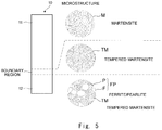
- Fig. 5 is a schematic plan view showing microstructures of the steel plate member that has been produced.
- Fig. 5 schematically shows the respective microstructures of the first region 11, the second region 12, and the boundary region. Note that the microstructures of the steel plate member 10 shown in Fig. 5 are identical to the microstructures of the steel plate member 10 which has been subjected to the local tempering step shown in the right part of Fig. 4 .
- the steel plate member 10 includes the first region 11 containing martensite M which is hard and the second region 12 containing ferrite F and pearlite P (ferrite/pearlite FP) which are soft.
- the second region 12 when the second region 12 is reheated to a temperature lower than the austenite transformation finish temperature A3 in the local tempering step, the second region 12 also contains tempered martensite TM which is soft.
- a major portion of the boundary region (a region heated to a temperature equal to or lower than the austenite transformation start temperature A1) formed between the first region 11 and the second region 12 has a microstructure consisting of only the tempered martensite TM.
- both the tempered martensite TM and the martensite M are present. With decreasing distance from the first region 11, the amount of the tempered martensite TM decreases and the amount of the martensite M increases.
- the boundary region of the steel plate member 10 has a microstructure consisting of only the tempered martensite TM and does not have an unstable microstructure in which martensite which is hard and ferrite and pearlite which are soft are present. It is therefore possible to prevent a fracture in the boundary region between the first region 11 which is hard and the second region 12 which is soft. While both the tempered martensite TM and the martensite M are present in the vicinity of the first region 11 in the boundary region, a fracture can be prevented because of a small difference in hardness between the tempered martensite TM and the martensite M adjacent to each other.
- the boundary region of the steel plate member 10 is heated to a higher temperature and thus becomes softer with decreasing distance from the second region 12 heated in the local tempering step. That is, the boundary region of the steel plate member 10 becomes softer gradually in the direction from the side of the first region 11 which is hard to the side of the second region 12 which is soft. It is therefore possible to prevent a fracture in the boundary region between the first region 11 which is hard and the second region 12 which is soft more efficiently.
- the second region 12 which is the soft region, includes the microstructure in which ferrite/pearlite FP and the tempered martensite TM are present.
- the second region 12 which is the soft region, includes the microstructure in which ferrite/pearlite FP and the tempered martensite TM are present.
- both ferrite/pearlite FP and the tempered martensite TM heated to the austenite transformation start temperature A1 are soft, a fracture is not likely to occur also in the second region 12.
- one feature of the method for producing the steel plate member according to the first embodiment is to correct the shape of the second region 12 of the steel plate member 10 in the cooling process of the local tempering step.
- the shape of the second region 12 of the steel plate member 10 is corrected in a temperature range from a temperature that is equal to or lower than the austenite transformation start temperature A1 to a temperature that is equal to or higher than a temperature at which transformation to ferrite and pearlite is finished (ferrite/pearlite transformation finish temperature) while maintaining a cooling rate slower than the lower critical cooling rate.
- the transformation superplastic phenomenon appears in accordance with the transformation from austenite to ferrite/pearlite. Therefore, the shape of the second region 12 of the steel plate member 10 can be easily corrected with a small amount of power and the accuracy of the dimensions in the steel plate member is improved.
- the correction can be started from a temperature higher than the austenite transformation start temperature A1 in the cooling process.
- the correction can be started from the reheating process of the local tempering step. Further, the correction can be continued to a temperature lower than the ferrite/pearlite transformation finish temperature.
- Fig. 6 is a schematic perspective view of a correcting device for correcting the shape of the second region 12 of the steel plate member 10 in the cooling process of the local tempering step.
- a correcting device 40 includes an upper die 41 and a lower die 42, which are metal correcting dies.
- the second region 12 of the steel plate member 10 which is in the middle of being cooled is sandwiched between the upper die 41 and the lower die 42 and corrected.
- Fig. 6 shows a state in which the steel plate member 10 is pressed by the upper die 41 and the lower die 42 and corrected.
- the correcting device 40 has a basic configuration that is similar to that of the section where the second region 12 is formed in the hot press forming apparatus 20 shown in Fig. 2 .
- a recess 41a that is recessed in a trapezoidal cross section is provided on the lower surface of the upper die 41 so as to extend in the axial direction (y-axis direction).
- a projection 42a having a trapezoidal cross section is provided on the upper surface of the lower die 42 so as to extend in the axial direction (y-axis direction).
- a plurality of pins 41b and a plurality of pins 42b for locally pressing the second region 12 of the steel plate member 10 are provided on a pressing surface (lower surface) of the upper die 41 and a pressing surface (upper surface) of the lower die 42.
- the plurality of pins 41b provided on the lower surface of the upper die 41 and the plurality of pins 42b provided on the upper surface of the lower die 42 are provided in such a way that they are opposed to each other via the second region 12 of the steel plate member 10.
- Fig. 7 is a schematic cross-sectional view according to a modified example of the correcting device.
- the correcting device shown in Fig. 7 also includes an upper die 41 and a lower die 42, which are correcting dies.
- the pins 41b and 42b shown in Fig. 6 are not provided, and heaters 41c and 42c, which are heating mechanisms, are provided inside the upper die 41 and the lower die 42.
- heaters 41c and 42c which are heating mechanisms
- the heaters 41c and 42c are respectively provided in the vicinity of the lower surface of the upper die 41 and the upper surface of the lower die 42 in such a way that the pressing surface (lower surface) of the upper die 41 and the pressing surface (upper surface) of the lower die 42 can be uniformly heated, although the configuration of the heaters 41c and 42c is not limited in particular.
- the upper die 41 and the lower die 42 can be respectively heated by the heaters 41c and 42c. Therefore, heat removal from the second region 12 of the steel plate member 10 by the upper die 41 and the lower die 42 is suppressed, and the shape of the second region 12 of the steel plate member 10 can be corrected while maintaining a cooling rate slower than the lower critical cooling rate. Further, since the second region 12 of the steel plate member 10 can be pressed by the whole lower surface of the upper die 41 and the whole upper surface of the lower die 42, it is possible to perform correction with a higher accuracy.
- the shape of the second region 12 may be corrected using the upper die 41 and the lower die 42 having at least the pressing surfaces made of a heat insulating material.
- the shape of the second region 12 of the steel plate member 10 can be corrected while maintaining a cooling rate slower than the lower critical cooling rate.
- FIGs. 8 and 9 are perspective views of the specific example of the steel plate member produced using the method for producing the steel plate member according to the first embodiment.
- the arrows shown in Figs. 8 and 9 indicate the respective directions in a vehicle.
- a steel plate member 50 shown in Fig. 8 is one example of a side member that is a vehicle member, and more specifically, a front side member inner.
- the steel plate member 50 shown in Fig. 8 has a hat-shaped cross section including a top plate 50a, side walls 50b, and flange parts 50c extending in a front-rear direction. More specifically, the pair of side walls 50b are formed outward from end parts of the top plate 50a in the width direction extending in the front-rear direction. Further, each of the flange parts 50c projects outward (i.e., upper side or lower side in Fig. 8 ) from an end part of the corresponding side wall 50b.
- the steel plate member 50 shown in Fig. 8 includes a first region 51 containing martensite M which is hard and a second region 52 containing ferrite F and pearlite P (ferrite/pearlite FP) which are soft.
- the steel plate member 50 can be produced by quenching the entire part of the steel plate member 50 while hot press forming it and then locally tempering only the second region 52 using the method for producing the steel plate member according to this embodiment.
- the front second region 52 in the steel plate member 50 shown in Fig. 8 has a low strength and an excellent impact absorption property, while the rear first region 51 has a high strength. With this configuration, the steel plate member 50 is able to achieve both a high strength and excellent impact absorption characteristics.
- a steel plate member 60 shown in Fig. 9 is a steel plate member for pillars that are vehicle members, more specifically, a center pillar reinforcement.
- the steel plate member 60 includes a main body part 601, an upper flange part 602, and a lower flange part 603.
- the main body part 601 is a section having a hat-shaped cross section including a top plate 601a, side walls 601b, and flange parts 601c extending in a vertical direction. More specifically, the pair of side walls 601b are formed inward from end parts of the top plate 601a in the width direction extending in the vertical direction. Further, each of the flange parts 601c projects outward (the front-rear direction shown in Fig. 9 ) from the end part of the corresponding side wall 601b.
- the main body part 601 is slightly curved as a whole so as to project outward. Furthermore, an upper end part and a lower end part of the main body part 601 are formed in a T shape in a plan view extending in the width direction (the front-rear direction shown in Fig. 9 ). Here, the lower end part is extended in the width direction (the front-rear direction shown in Fig. 9 ) to be wider than the upper end part.
- the upper flange part 602 includes a plate surface that rises outward from an upper end part of the main body part 601 and a plate surface that projects upward from an outer end part of the other surface. That is, the upper flange part 602 is a part having an L-shaped cross section that extends in the width direction (the front-rear direction shown in Fig. 9 ).
- the lower flange part 603 is a flat part projecting to be extended from a lower end part of the top plate 601a to a lower side extending in the width direction (the front-rear direction shown in Fig. 9 ).
- the steel plate member 60 shown in Fig. 9 also includes a first region 61 containing martensite M which is hard and a second region 62 containing ferrite F and pearlite P (ferrite/pearlite FP) which are soft.
- the steel plate member 60 can be produced by quenching the entire part of the steel plate member 60 while hot press forming it and subsequently locally tempering only the second region 62 using the method for producing the steel plate member according to this embodiment.
- a region from a lower part of the main body part 601 to the lower flange part 603, which is the second region 62, has a low strength and an excellent impact absorption property.
- a region from a part in the vicinity of the central part of the main body part 601 to the upper flange part 602, which is the first region 61 has a high strength. According to this configuration, the steel plate member 60 is able to achieve both a high strength and excellent impact absorption characteristics.
- a quenching material of steel plate used for hot stamping made of flat (thickness: 2.0 mm, width: 35 mm, and length: 140 mm) manganese-boron steel (22MnB5 steel) was used as the steel plate member 10.
- the austenite transformation start temperature A1 of this type of steel is 727°C
- the austenite transformation finish temperature A3 is 800°C
- the ferrite/pearlite transformation finish temperature is 550°C.
- Fig. 10 is a schematic cross-sectional view of a correcting device according to the experimental example.
- the y-axis direction shown in Fig. 10 corresponds to a longitudinal direction of the steel plate member 10.
- the steel plate member 10 to which the initial bending was added was reheated to 740°C, which is a temperature higher than the austenite transformation start temperature A1, and then cooled at a cooling rate slower than the lower critical cooling rate by air cooling for tempering.
- the steel plate member 10 was sandwiched between the upper die 41 and the lower die 42 shown in Fig. 10 , and the shape thereof was corrected.
- the cooling rate was maintained at a cooling rate slower than the lower critical cooling rate.
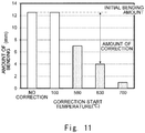
- the correction start temperature was changed to 100°C, 580°C, 630°C, 700°C, and the change in the amount of bending (i.e., the amount of correction) was investigated.
- the shape of the steel plate member 10 was corrected by only the weight of the upper die 41 itself without giving a load for the correction.
- Fig. 11 is a bar graph indicating a relation between the correction start temperature and the amount of bending.
- the amount of bending was substantially the same as that when the correction was not performed, which means that the steel plate member 10 could not be efficiently corrected.
- dots in Fig. 11 at 580°C, 630°C, and 700°C where the correction start temperature exceeded the ferrite/pearlite transformation finish temperature (550°C), the amount of bending has abruptly decreased as the temperature increases. That is, it has been found that the amount of correction has abruptly increased and the steel plate member 10 could be efficiently corrected with a small amount of power.
- the steel plate member 60 shown in Fig. 9 was produced from a flat steel plate used for hot stamping having a thickness of 1.8 mm made of manganese-boron steel (22MnB5 steel) by the method for producing the steel plate member according to the first embodiment.
- Fig. 12 is a temperature chart showing conditions of local tempering according to the Example.
- Fig. 12 shows temperature profiles in two regions of the first region 61 and the second region 62.
- the steel plate member 60 was cooled at a cooling rate that is lower than the upper critical cooling rate by air cooling so that the second region 62 is not transformed into martensite.
- the steel plate member 10 was sandwiched between the upper die 41 and the lower die 42 shown in Fig. 6 and then corrected.
- the load for the correction was set to 20T.
- Fig. 13 is a graph showing the amount of deviation from the reference position in the measurement points P1-P5.
- the Example is shown by a solid line and the comparative example is shown by a dashed line.
- the width of the amount of deviation from the reference position is 4.5 mm in the comparative example
- the width of the amount of deviation from the reference position is 1.0 mm in this Example, and the accuracy of the dimensions in the steel plate member has been dramatically improved.
Landscapes
- Chemical & Material Sciences (AREA)
- Engineering & Computer Science (AREA)
- Mechanical Engineering (AREA)
- Physics & Mathematics (AREA)
- Thermal Sciences (AREA)
- Crystallography & Structural Chemistry (AREA)
- Materials Engineering (AREA)
- Metallurgy (AREA)
- Organic Chemistry (AREA)
- Heat Treatment Of Articles (AREA)
Abstract
Description
- The present disclosure relates to a method for producing a steel plate member, and in particular, to a method for producing a steel plate member including a hard region containing martensite and a soft region containing ferrite and pearlite.
- In recent years, steel plate members including a hard region resistant to an impact and a soft region for absorbing an impact have been developed, for example, as structural members for automobiles. As disclosed in Japanese Unexamined Patent Application Publication No.
2019-073793 - The present inventors have found the following problem regarding the method for producing the steel plate member including the hard region and the soft region.
- In the method disclosed in Japanese Unexamined Patent Application Publication No.
2019-073793 - The present disclosure has been made in light of the above circumstances. An object of the present disclosure is to provide a method for producing a steel plate member capable of suppressing degradation in the accuracy of the dimensions in a steel plate member including a hard region and a soft region.
- A method for producing a steel plate member according to one aspect of the present disclosure includes:
- a quenching step for heating the steel plate member to a temperature higher than an austenite transformation finish temperature A3 and subsequently cooling the steel plate member at a cooling rate faster than an upper critical cooling rate; and
- a tempering step for reheating a second region of the steel plate member to a temperature higher than an austenite transformation start temperature A1 without reheating a first region of the steel plate member after quenching and subsequently cooling the steel plate member at a cooling rate slower than a lower critical cooling rate, in which
- a hard region containing martensite is formed in the first region and a soft region containing ferrite and pearlite is formed in the second region.
- In the cooling process of the tempering step,
the shape of the second region is corrected in a temperature range from a temperature that is equal to or lower than the austenite transformation start temperature A1 to a temperature that is equal to or higher than a temperature at which transformation into ferrite and pearlite is finished while maintaining the cooling rate slower than the lower critical cooling rate. - In the method for producing the steel plate member according to one aspect of the present disclosure, in the cooling process of the tempering step, the shape of the second region is corrected in the temperature range from a temperature that is equal to or lower than the austenite transformation start temperature A1 to a temperature that is equal to or higher than the temperature at which transformation into ferrite and pearlite is finished while maintaining a cooling rate slower than the lower critical cooling rate. Since the transformation superplastic phenomenon appears in accordance with the transformation from austenite to ferrite/pearlite, the shape of the second region of the steel plate member can be easily corrected with a small amount of power and the accuracy of the dimensions in the steel plate member is improved.
- When the shape of the second region is corrected, the second region may be locally pressed by a correcting die having a pressing surface provided with a plurality of pins. Alternatively, the second region may be pressed by a correcting die including a heating mechanism therein. Alternatively, the second region may be pressed by a correcting die having at least a pressing surface made of a heat insulating material.
- According to the aforementioned configuration, the shape of the second region of the steel plate member can be corrected while maintaining a cooling rate slower than the lower critical cooling rate.
- In the reheating process of the tempering step, the second region may be reheated to a temperature between the austenite transformation start temperature A1 and the austenite transformation finish temperature A3. Compared to the case in which the second region is reheated to a temperature equal to or higher than the austenite transformation finish temperature A3, the energy efficiency becomes higher and the strength in the second region is improved.
- In the reheating process of the tempering step, the second region may be reheated by induction heating. The second region of the steel plate member may be rapidly heated.
- According to the present disclosure, it is possible to provide a method for producing a steel plate member capable of suppressing degradation in the accuracy of the dimensions in the steel plate member including the hard region and the soft region.
- The above and other objects, features and advantages of the present disclosure will become more fully understood from the detailed description given hereinbelow and the accompanying drawings which are given by way of illustration only, and thus are not to be considered as limiting the present disclosure.
-
-
Fig. 1 is a temperature chart showing a method for producing a steel plate member according to a first embodiment; -
Fig. 2 is a perspective view showing one example of a hot press forming apparatus; -
Fig. 3 is a schematic perspective view of an induction heating apparatus for reheating asecond region 12 of asteel plate member 10 in a local tempering step; -
Fig. 4 is a schematic plan view showing a change in microstructures of the steel plate member in the local tempering step when only thesecond region 12 of thesteel plate member 10 is reheated to a temperature between an austenite transformation start temperature A1 and an austenite transformation finish temperature A3; -
Fig. 5 is a schematic plan view showing microstructures of a steel plate member that has been produced; -
Fig. 6 is a schematic perspective view of a correcting device for correcting the shape of thesecond region 12 of thesteel plate member 10 in a cooling process of the local tempering step; -
Fig. 7 is a schematic cross-sectional view of a modified example of the correcting device; -
Fig. 8 is a perspective view of a specific example of the steel plate member produced using the method for producing the steel plate member according to the first embodiment; -
Fig. 9 is a perspective view of a specific example of the steel plate member produced using the method for producing the steel plate member according to the first embodiment; -
Fig. 10 is a schematic cross-sectional view of a correcting device according to an experimental example; -
Fig. 11 is a bar graph showing a relation between a correction start temperature and an amount of bending; -
Fig. 12 is a temperature chart showing conditions of local tempering according to an Example; and -
Fig. 13 is a graph showing an amount of deviation from a reference position in measurement points P1-P5. - Hereinafter, specific embodiments to which the present disclosure is applied will be described in detail with reference to the drawings. However, the present disclosure is not limited to the following embodiments. Further, the following descriptions and drawings are simplified as appropriate for clarity of explanation.
- First, with reference to
Fig. 1 , a method for producing a steel plate member according to a first embodiment will be described. The method for producing the steel plate member according to the first embodiment is suitable as a method for producing a steel plate member including a hard region resistant to an impact and a soft region for absorbing an impact, the steel plate member being for use, for example, in automobiles. -
Fig. 1 is a temperature chart showing the method for producing the steel plate member according to the first embodiment. InFig. 1 , the horizontal axis represents time (s) and the vertical axis represents temperature (°C). As shown inFig. 1 , the method for producing the steel plate member according to the first embodiment includes a quenching step and a local tempering step. In the method for producing the steel plate member according to the first embodiment, the quenching step is performed first and then the local tempering step is performed. - First, in the quenching step, the entire steel plate member is heated to a temperature higher than an austenite transformation finish temperature A3. In this case, the microstructure of the entire steel plate member converts from ferrite and pearlite to an austenite single phase. After that, the steel plate member is cooled at a cooling rate higher than an upper critical cooling rate. Thus, austenite is transformed into martensite and the microstructure of the entire steel plate member is converted to martensite which is hard.
- In the quenching step, the steel plate member may be simply cooled after it is heated. Alternatively, the steel plate member may be cooled while being press formed. Since this press-forming is hot press forming, a high-strength steel plate member can be obtained by performing quenching at the time of the press forming while avoiding the springback that occurs during cold press forming. This hot press forming is typically called hot stamping. The steel plate used for hot stamping is, for example, but not limited to, a steel plate made of manganese-boron steel having a thickness of about 1-4 mm.
-
Fig. 2 is a perspective view showing an example of a hot press forming apparatus. As shown inFig. 2 , a hotpress forming apparatus 20 includes anupper die 21 and alower die 22, which are both dies. As shown inFig. 2 , a heated steel plate which has, for example, a flat shape, is sandwiched between theupper die 21 and thelower die 22, and cooled while being press formed, and thus quenched. Thesteel plate member 10 after press forming shown inFig. 2 has a hat-shaped cross section including atop plate 10a,side walls 10b, andflange parts 10c extending in a y-axis direction. More specifically, the pair ofside walls 10b are formed downward from end parts of thetop plate 10a in a width direction (x-axis direction) extending in the y-axis direction. Further, each of theflange parts 10c projects outward from a lower end part (z-axis negative direction side) of thecorresponding side wall 10b. - Thus, as shown in
Fig. 2 , arecess 21a that is recessed in a trapezoidal cross section is provided on a lower surface of theupper die 21 so as to extend in an axial direction (y-axis direction). Likewise, aprojection 22a having a trapezoidal cross section is provided on an upper surface of thelower die 22 so as to extend in the axial direction (y-axis direction).Fig. 2 shows a state in which theupper die 21 and thelower die 22 are separated from each other after press-forming thesteel plate member 10. - As a matter of course, the right-handed xyz orthogonal coordinates shown in
Fig. 2 and other drawings are for convenience to describe the positional relationship of the components. Commonly, a z-axis positive direction is vertically upward and an xy plane is a horizontal plane. - Next, as shown in
Fig. 1 , in the local tempering step, only a part of the region of the steel plate member is reheated and softened. Specifically, as shown inFig. 1 , afirst region 11 of the steel plate member is not reheated and only asecond region 12 of the steel plate member is reheated to a temperature higher than the austenite transformation start temperature A1. - Since the normal tempering temperature is lower than the austenite transformation start temperature A1, the heating temperature in the local tempering step according to the first embodiment is higher than the normal tempering temperature.
- Further, while the method of heating the
second region 12 of the steel plate member in the local tempering step is not particularly limited, induction heating is, for example, used.Fig. 3 is a schematic perspective view of an induction heating apparatus for reheating thesecond region 12 of thesteel plate member 10 in the local tempering step. As shown inFig. 3 , aninduction heating apparatus 30 is a high-frequency induction heating apparatus including acoil 31 and a high-frequency power supply 32. - As shown in
Fig. 3 , thecoil 31 is a horizontally-positioned plate member having a U-shaped cross section so as to cover the entire upper and lower surfaces of thesteel plate member 10 in the width direction (x-axis direction). As shown inFig. 3 , thecoil 31 is provided with irregularities that correspond to those of thesteel plate member 10 having a hat-shaped cross section. Then the high-frequency power supply 32 is connected to respective ends of thecoil 31. - The shape of the
coil 31 shown inFig. 3 is merely one example and may be split, for example, into a plurality of parts. - As shown in
Fig. 3 , only thesecond region 12 of thesteel plate member 10 is inserted inside thecoil 31 and is heated to a temperature higher than the austenite transformation start temperature A1 by induction heating. Thesecond region 12 of thesteel plate member 10 is reheated to, but not limited to, a temperature lower than the austenite transformation finish temperature A3 as shown in, for example,Fig. 1 . - Since the
first region 11 of thesteel plate member 10 is exposed from thecoil 31, it is not subjected to induction heating and is not thermally affected by heat conduction from thesecond region 12. On the other hand, the boundary region between thefirst region 11 and thesecond region 12 is heated to a temperature lower than the austenite transformation start temperature A1 by heat conduction from thesecond region 12 and is thermally affected. In other words, the boundary region is a region that is heated to a temperature lower than the austenite transformation start temperature A1 and is thermally affected. - In the high-frequency induction heating, the heating efficiency abruptly drops at the Curie point where the
steel plate member 10 loses the magnetic properties, and thus the increase in the temperature of the heated region becomes difficult around the Curie point. Since austenite is non-magnetic while martensite, ferrite, and pearlite are ferromagnetic, the Curie point lies between the austenite transformation start temperature A1 and the austenite transformation finish temperature A3. - Thus, with the use of high-frequency induction heating, only the
second region 12 of thesteel plate member 10 can be rapidly heated, and the temperature to which thesecond region 12 is heated can be easily and accurately kept at a temperature between the austenite transformation start temperature A1 and the austenite transformation finish temperature A3. Since rapid heating of only thesecond region 12 of thesteel plate member 10 is possible, the boundary region thermally affected by heat conduction from thesecond region 12 can be narrowed. - After that, as shown in
Fig. 1 , the steel plate member is cooled at a cooling rate slower than the lower critical cooling rate so as not to cause martensite transformation of thesecond region 12. At this time, as shown by the dashed arrow inFig. 1 , after the completion of the conversion from austenite to ferrite/pearlite, the steel plate member may be rapidly cooled. Since the time for producing the steel plate member is reduced by rapid cooling, the production efficiency can be improved. -
Fig. 1 schematically shows a martensite transformation start temperature Ms, a martensite transformation finish temperature Mf, and a ferrite/pearlite nose in a Continuous Cooling Transformation (CCT) phase diagram. That is,Fig. 1 schematically shows the process in which thesecond region 12 having been reheated to a temperature between the austenite transformation start temperature A1 and the austenite transformation finish temperature A3 is cooled at a cooling rate slower than the lower critical cooling rate. - With reference to
Fig. 4 , a change in microstructures in the local tempering step will be described.Fig. 4 is a schematic plan view showing the change in the microstructures of the steel plate member in the local tempering step when only thesecond region 12 of thesteel plate member 10 is reheated to a temperature between the austenite transformation start temperature A1 and the austenite transformation finish temperature A3. - First, the microstructure of the
steel plate member 10 which has been subjected to the quenching step but has yet to be subjected to the local tempering step shown in the left part ofFig. 4 will be described. As shown in the left part ofFig. 4 , the entire microstructure of thesteel plate member 10 before the local tempering step (i.e., after the quenching step) contains martensite M. - Next, a microstructure of the
steel plate member 10 which is being heated in the local tempering step shown in the middle part ofFig. 4 will be described. As shown in the temperature chart inFig. 1 , only thesecond region 12 of thesteel plate member 10 is reheated to a temperature between the austenite transformation start temperature A1 and the austenite transformation finish temperature A3 during the heating in the local tempering step. - Therefore, as shown in the middle part of
Fig. 4 , during the heating in the local tempering step, the martensite M is converted to tempered martensite TM and a part of the tempered martensite TM is further converted to austenite A in thesecond region 12. That is, the microstructure of thesecond region 12 becomes a mixed structure of the tempered martensite TM and the austenite A. Since the temperature of the heatedsecond region 12 is close to the austenite transformation start temperature A1 in the vicinity of the boundary region in thesecond region 12, the amount of the austenite A decreases while the amount of the tempered martensite TM increases. - The tempered martensite TM is used herein to collectively refer to all structures resulting from the reheating-induced softening of the martensite M and encompasses troostite and sorbite.
- Meanwhile, the
first region 11 of thesteel plate member 10 is not reheated and thus is not thermally affected. The microstructure of thefirst region 11 therefore remains unchanged from the martensite M. - The boundary region between the
first region 11 and thesecond region 12 is heated to a temperature lower than the austenite transformation start temperature A1 by heat conduction from thesecond region 12 and thermally affected. This converts the microstructure of the boundary region from the martensite M to the tempered martensite TM. - More specifically, the temperature of the boundary region becomes higher and closer to the austenite transformation start temperature A1 with decreasing distance from the
second region 12. For this reason, the microstructure on the side of thesecond region 12 of the boundary region, which is a major portion of the boundary region, is consisting of only the tempered martensite TM. In the vicinity of thefirst region 11 in the boundary region, both the tempered martensite TM and the martensite M are present. With decreasing distance from thefirst region 11 which is consisting of only the martensite M, the amount of the tempered martensite TM decreases and the amount of the martensite M increases. - As stated above, since the amount of the tempered martensite TM heated to a high temperature increases with decreasing distance from the
second region 12, the boundary region becomes softer gradually in the direction from thefirst region 11 which is hard to thesecond region 12 which is soft. - Next, the microstructure of the
steel plate member 10 which has been subjected to the local tempering step shown in the right part ofFig. 4 will be described. As shown inFig. 1 , the cooling process in the local tempering step cools thesteel plate member 10 at a cooling rate slower than the lower critical cooling rate. Thus, as shown in the right part ofFig. 4 , the austenite A in thesecond region 12 that has appeared during the heating is converted to ferrite and pearlite (ferrite/pearlite) FP. As a result, the microstructure of thesecond region 12 becomes a mixed structure of the tempered martensite TM and ferrite/pearlite FP. The microstructure of thefirst region 11 remains unchanged from the martensite M. The microstructure of the boundary region remains unchanged from the tempered martensite TM as well. - When the
second region 12 is reheated to a temperature higher than the austenite transformation finish temperature A3 in the local tempering step, thesecond region 12 after the cooling becomes a microstructure consisting of only ferrite/pearlite FP, the strength thereof is further reduced and becomes soft. Then a mixed structure of the tempered martensite TM and ferrite/pearlite FP appears on the side of thesecond region 12 in the boundary region and a single structure containing only the tempered martensite TM appears on the side of thefirst region 11 in the boundary region. -
Fig. 5 is a schematic plan view showing microstructures of the steel plate member that has been produced.Fig. 5 schematically shows the respective microstructures of thefirst region 11, thesecond region 12, and the boundary region. Note that the microstructures of thesteel plate member 10 shown inFig. 5 are identical to the microstructures of thesteel plate member 10 which has been subjected to the local tempering step shown in the right part ofFig. 4 . - As shown in
Fig. 5 , thesteel plate member 10 includes thefirst region 11 containing martensite M which is hard and thesecond region 12 containing ferrite F and pearlite P (ferrite/pearlite FP) which are soft. As shown inFig. 1 , when thesecond region 12 is reheated to a temperature lower than the austenite transformation finish temperature A3 in the local tempering step, thesecond region 12 also contains tempered martensite TM which is soft. - A major portion of the boundary region (a region heated to a temperature equal to or lower than the austenite transformation start temperature A1) formed between the
first region 11 and thesecond region 12 has a microstructure consisting of only the tempered martensite TM. In the vicinity of thefirst region 11 in the boundary region, both the tempered martensite TM and the martensite M are present. With decreasing distance from thefirst region 11, the amount of the tempered martensite TM decreases and the amount of the martensite M increases. - As described above, the boundary region of the
steel plate member 10 has a microstructure consisting of only the tempered martensite TM and does not have an unstable microstructure in which martensite which is hard and ferrite and pearlite which are soft are present. It is therefore possible to prevent a fracture in the boundary region between thefirst region 11 which is hard and thesecond region 12 which is soft. While both the tempered martensite TM and the martensite M are present in the vicinity of thefirst region 11 in the boundary region, a fracture can be prevented because of a small difference in hardness between the tempered martensite TM and the martensite M adjacent to each other. - Further, the boundary region of the
steel plate member 10 is heated to a higher temperature and thus becomes softer with decreasing distance from thesecond region 12 heated in the local tempering step. That is, the boundary region of thesteel plate member 10 becomes softer gradually in the direction from the side of thefirst region 11 which is hard to the side of thesecond region 12 which is soft. It is therefore possible to prevent a fracture in the boundary region between thefirst region 11 which is hard and thesecond region 12 which is soft more efficiently. - In the
steel plate member 10, thesecond region 12, which is the soft region, includes the microstructure in which ferrite/pearlite FP and the tempered martensite TM are present. However, since both ferrite/pearlite FP and the tempered martensite TM heated to the austenite transformation start temperature A1 are soft, a fracture is not likely to occur also in thesecond region 12. - As shown in
Fig. 1 , one feature of the method for producing the steel plate member according to the first embodiment is to correct the shape of thesecond region 12 of thesteel plate member 10 in the cooling process of the local tempering step. Specifically, the shape of thesecond region 12 of thesteel plate member 10 is corrected in a temperature range from a temperature that is equal to or lower than the austenite transformation start temperature A1 to a temperature that is equal to or higher than a temperature at which transformation to ferrite and pearlite is finished (ferrite/pearlite transformation finish temperature) while maintaining a cooling rate slower than the lower critical cooling rate. - In the temperature range from a temperature that is equal to or lower than the austenite transformation start temperature A1 to a temperature that is equal to or higher than the temperature at which ferrite/pearlite transformation is finished in the cooling process of the local tempering step, in the
second region 12 of thesteel plate member 10, the transformation superplastic phenomenon appears in accordance with the transformation from austenite to ferrite/pearlite. Therefore, the shape of thesecond region 12 of thesteel plate member 10 can be easily corrected with a small amount of power and the accuracy of the dimensions in the steel plate member is improved. - Note that the correction can be started from a temperature higher than the austenite transformation start temperature A1 in the cooling process. Alternatively, the correction can be started from the reheating process of the local tempering step. Further, the correction can be continued to a temperature lower than the ferrite/pearlite transformation finish temperature.
-
Fig. 6 is a schematic perspective view of a correcting device for correcting the shape of thesecond region 12 of thesteel plate member 10 in the cooling process of the local tempering step. As shown inFig. 6 , a correctingdevice 40 includes anupper die 41 and alower die 42, which are metal correcting dies. Thesecond region 12 of thesteel plate member 10 which is in the middle of being cooled is sandwiched between theupper die 41 and thelower die 42 and corrected.Fig. 6 shows a state in which thesteel plate member 10 is pressed by theupper die 41 and thelower die 42 and corrected. - As shown in
Fig. 6 , the correctingdevice 40 has a basic configuration that is similar to that of the section where thesecond region 12 is formed in the hotpress forming apparatus 20 shown inFig. 2 . Specifically, in a manner similar to theupper die 21 for press forming shown inFig. 2 , arecess 41a that is recessed in a trapezoidal cross section is provided on the lower surface of theupper die 41 so as to extend in the axial direction (y-axis direction). Further, in a manner similar to thelower die 22 for press forming shown inFig. 2 , aprojection 42a having a trapezoidal cross section is provided on the upper surface of thelower die 42 so as to extend in the axial direction (y-axis direction). - A plurality of
pins 41b and a plurality ofpins 42b for locally pressing thesecond region 12 of thesteel plate member 10 are provided on a pressing surface (lower surface) of theupper die 41 and a pressing surface (upper surface) of thelower die 42. As shown inFig. 6 , the plurality ofpins 41b provided on the lower surface of theupper die 41 and the plurality ofpins 42b provided on the upper surface of thelower die 42 are provided in such a way that they are opposed to each other via thesecond region 12 of thesteel plate member 10. - Since the
aforementioned pins second region 12 of thesteel plate member 10, the area in which theupper die 41 and thelower die 42 contact thesecond region 12 of thesteel plate member 10 decreases. As a result, heat removal from thesecond region 12 of thesteel plate member 10 by theupper die 41 and thelower die 42 is suppressed, and the shape of thesecond region 12 of thesteel plate member 10 can be corrected while maintaining a cooling rate slower than the lower critical cooling rate. -
Fig. 7 is a schematic cross-sectional view according to a modified example of the correcting device. The correcting device shown inFig. 7 also includes anupper die 41 and alower die 42, which are correcting dies. In the correcting device shown inFig. 7 , thepins Fig. 6 are not provided, andheaters upper die 41 and thelower die 42. In the correcting device shown inFig. 7 , theheaters upper die 41 and the upper surface of thelower die 42 in such a way that the pressing surface (lower surface) of theupper die 41 and the pressing surface (upper surface) of thelower die 42 can be uniformly heated, although the configuration of theheaters - In the correcting
device 40 shown inFig. 7 , theupper die 41 and thelower die 42 can be respectively heated by theheaters second region 12 of thesteel plate member 10 by theupper die 41 and thelower die 42 is suppressed, and the shape of thesecond region 12 of thesteel plate member 10 can be corrected while maintaining a cooling rate slower than the lower critical cooling rate. Further, since thesecond region 12 of thesteel plate member 10 can be pressed by the whole lower surface of theupper die 41 and the whole upper surface of thelower die 42, it is possible to perform correction with a higher accuracy. - Instead of providing the
heaters second region 12 may be corrected using theupper die 41 and thelower die 42 having at least the pressing surfaces made of a heat insulating material. Likewise, the shape of thesecond region 12 of thesteel plate member 10 can be corrected while maintaining a cooling rate slower than the lower critical cooling rate. - Next, with reference to
Figs. 8 and9 , a specific example of the steel plate member produced using the method for producing the steel plate member according to the first embodiment will be described.Figs. 8 and9 are perspective views of the specific example of the steel plate member produced using the method for producing the steel plate member according to the first embodiment. The arrows shown inFigs. 8 and9 indicate the respective directions in a vehicle. - The applications and the shapes of the steel plate member shown in
Figs. 8 and9 are merely examples and the applications and the shapes of the steel plate member produced using the method for producing the steel plate member according to the first embodiment should not be limited. - A
steel plate member 50 shown inFig. 8 is one example of a side member that is a vehicle member, and more specifically, a front side member inner. - The
steel plate member 50 shown inFig. 8 has a hat-shaped cross section including atop plate 50a,side walls 50b, andflange parts 50c extending in a front-rear direction. More specifically, the pair ofside walls 50b are formed outward from end parts of thetop plate 50a in the width direction extending in the front-rear direction. Further, each of theflange parts 50c projects outward (i.e., upper side or lower side inFig. 8 ) from an end part of thecorresponding side wall 50b. - In a manner similar to the
steel plate member 10 shown inFig. 5 , thesteel plate member 50 shown inFig. 8 includes afirst region 51 containing martensite M which is hard and asecond region 52 containing ferrite F and pearlite P (ferrite/pearlite FP) which are soft. Thesteel plate member 50 can be produced by quenching the entire part of thesteel plate member 50 while hot press forming it and then locally tempering only thesecond region 52 using the method for producing the steel plate member according to this embodiment. The frontsecond region 52 in thesteel plate member 50 shown inFig. 8 has a low strength and an excellent impact absorption property, while the rearfirst region 51 has a high strength. With this configuration, thesteel plate member 50 is able to achieve both a high strength and excellent impact absorption characteristics. - A
steel plate member 60 shown inFig. 9 is a steel plate member for pillars that are vehicle members, more specifically, a center pillar reinforcement. - As shown in
Fig. 9 , thesteel plate member 60 according to a second embodiment includes amain body part 601, anupper flange part 602, and alower flange part 603. - As shown in
Fig. 9 , themain body part 601 is a section having a hat-shaped cross section including atop plate 601a,side walls 601b, andflange parts 601c extending in a vertical direction. More specifically, the pair ofside walls 601b are formed inward from end parts of thetop plate 601a in the width direction extending in the vertical direction. Further, each of theflange parts 601c projects outward (the front-rear direction shown inFig. 9 ) from the end part of thecorresponding side wall 601b. - Further, the
main body part 601 is slightly curved as a whole so as to project outward. Furthermore, an upper end part and a lower end part of themain body part 601 are formed in a T shape in a plan view extending in the width direction (the front-rear direction shown inFig. 9 ). Here, the lower end part is extended in the width direction (the front-rear direction shown inFig. 9 ) to be wider than the upper end part. - The
upper flange part 602 includes a plate surface that rises outward from an upper end part of themain body part 601 and a plate surface that projects upward from an outer end part of the other surface. That is, theupper flange part 602 is a part having an L-shaped cross section that extends in the width direction (the front-rear direction shown inFig. 9 ). - The
lower flange part 603 is a flat part projecting to be extended from a lower end part of thetop plate 601a to a lower side extending in the width direction (the front-rear direction shown inFig. 9 ). - In a manner similar to the
steel plate member 10 shown inFig. 5 , thesteel plate member 60 shown inFig. 9 also includes afirst region 61 containing martensite M which is hard and asecond region 62 containing ferrite F and pearlite P (ferrite/pearlite FP) which are soft. Thesteel plate member 60 can be produced by quenching the entire part of thesteel plate member 60 while hot press forming it and subsequently locally tempering only thesecond region 62 using the method for producing the steel plate member according to this embodiment. - As shown in
Fig. 9 , in thesteel plate member 60, a region from a lower part of themain body part 601 to thelower flange part 603, which is thesecond region 62, has a low strength and an excellent impact absorption property. On the other hand, a region from a part in the vicinity of the central part of themain body part 601 to theupper flange part 602, which is thefirst region 61, has a high strength. According to this configuration, thesteel plate member 60 is able to achieve both a high strength and excellent impact absorption characteristics. - In the following, an experimental example regarding the method for producing the steel plate member according to the first embodiment will be described. A quenching material of steel plate used for hot stamping made of flat (thickness: 2.0 mm, width: 35 mm, and length: 140 mm) manganese-boron steel (22MnB5 steel) was used as the
steel plate member 10. The austenite transformation start temperature A1 of this type of steel is 727°C, the austenite transformation finish temperature A3 is 800°C, and the ferrite/pearlite transformation finish temperature is 550°C. - An initial bending amount of 12 mm was added to the above
steel plate member 10, as shown inFig. 10. Fig. 10 is a schematic cross-sectional view of a correcting device according to the experimental example. The y-axis direction shown inFig. 10 corresponds to a longitudinal direction of thesteel plate member 10. Thesteel plate member 10 to which the initial bending was added was reheated to 740°C, which is a temperature higher than the austenite transformation start temperature A1, and then cooled at a cooling rate slower than the lower critical cooling rate by air cooling for tempering. - At the timing when the
steel plate member 10 was cooled to a predetermined temperature in the cooling process of tempering, thesteel plate member 10 was sandwiched between theupper die 41 and thelower die 42 shown inFig. 10 , and the shape thereof was corrected. By using angular blocks made of ceramic, which is a heat insulating material, as theupper die 41 and thelower die 42, the cooling rate was maintained at a cooling rate slower than the lower critical cooling rate. The correction start temperature was changed to 100°C, 580°C, 630°C, 700°C, and the change in the amount of bending (i.e., the amount of correction) was investigated. The shape of thesteel plate member 10 was corrected by only the weight of theupper die 41 itself without giving a load for the correction. -
Fig. 11 is a bar graph indicating a relation between the correction start temperature and the amount of bending. As shown inFig. 11 , when the correction start temperature was 100°C, the amount of bending was substantially the same as that when the correction was not performed, which means that thesteel plate member 10 could not be efficiently corrected. On the other hand, as shown by dots inFig. 11 , at 580°C, 630°C, and 700°C where the correction start temperature exceeded the ferrite/pearlite transformation finish temperature (550°C), the amount of bending has abruptly decreased as the temperature increases. That is, it has been found that the amount of correction has abruptly increased and thesteel plate member 10 could be efficiently corrected with a small amount of power. - In the following, an Example of the method for producing the steel plate member according to the first embodiment will be described. The
steel plate member 60 shown inFig. 9 was produced from a flat steel plate used for hot stamping having a thickness of 1.8 mm made of manganese-boron steel (22MnB5 steel) by the method for producing the steel plate member according to the first embodiment. -
Fig. 12 is a temperature chart showing conditions of local tempering according to the Example.Fig. 12 shows temperature profiles in two regions of thefirst region 61 and thesecond region 62. - As shown in
Fig. 12 , after heating only thesecond region 62 of thesteel plate member 60 to 740°C, which is a temperature between the austenite transformation start temperature A1 and the austenite transformation finish temperature A3, thesteel plate member 60 was cooled at a cooling rate that is lower than the upper critical cooling rate by air cooling so that thesecond region 62 is not transformed into martensite. At the timing when thesteel plate member 60 was cooled to 630°C in the cooling process of tempering, thesteel plate member 10 was sandwiched between theupper die 41 and thelower die 42 shown inFig. 6 and then corrected. By locally pressing thesecond region 62 of thesteel plate member 60 by thepins - Regarding the produced
steel plate member 60, the amount of deviation from a reference position was measured in five measurement points P1-P5 shown inFig. 9 and the results of the measurement were compared to those of thesteel plate member 60 according to a comparative example produced without correction.Fig. 13 is a graph showing the amount of deviation from the reference position in the measurement points P1-P5. InFig. 13 , the Example is shown by a solid line and the comparative example is shown by a dashed line. As shown inFig. 13 , while the width of the amount of deviation from the reference position is 4.5 mm in the comparative example, the width of the amount of deviation from the reference position is 1.0 mm in this Example, and the accuracy of the dimensions in the steel plate member has been dramatically improved. - From the disclosure thus described, it will be obvious that the embodiments of the disclosure may be varied in many ways. Such variations are not to be regarded as a departure from the spirit and scope of the disclosure, and all such modifications as would be obvious to one skilled in the art are intended for inclusion within the scope of the following claims.
Claims (6)
- A method for producing a steel plate member (10), comprising:a quenching step for heating the steel plate member (10) to a temperature higher than an austenite transformation finish temperature A3 and subsequently cooling the steel plate member (10) at a cooling rate faster than an upper critical cooling rate; anda tempering step for reheating a second region (12) of the steel plate member (10) to a temperature higher than an austenite transformation start temperature A1 without reheating a first region (11) of the steel plate member (10) after quenching and subsequently cooling the steel plate member (10) at a cooling rate slower than a lower critical cooling rate, whereina hard region containing martensite is formed in the first region (11) and a soft region containing ferrite and pearlite is formed in the second region (12), andin the cooling process of the tempering step, the shape of the second region (12) is corrected in a temperature range from a temperature that is equal to or lower than the austenite transformation start temperature A1 to a temperature that is equal to or higher than a temperature at which transformation into ferrite and pearlite is finished while maintaining the cooling rate slower than the lower critical cooling rate.
- The method for producing the steel plate member (10) according to Claim 1, wherein, when the shape of the second region (12) is corrected, the second region (12) is locally pressed by a correcting die (41, 42) having a pressing surface provided with a plurality of pins (41b, 42b).
- The method for producing the steel plate member (10) according to Claim 1, wherein, when the shape of the second region (12) is corrected, the second region (12) is pressed by a correcting die (41, 42) including a heating mechanism (41c, 42c) therein.
- The method for producing the steel plate member (10) according to Claim 1, wherein, when the shape of the second region (12) is corrected, the second region (12) is pressed by a correcting die (41, 42) having at least a pressing surface made of a heat insulating material.
- The method for producing the steel plate member (10) according to any one of Claims 1 to 4, comprising, in the reheating process of the tempering step, the second region (12) is reheated to a temperature between the austenite transformation start temperature A1 and the austenite transformation finish temperature A3.
- The method for producing the steel plate member (10) according to any one of Claims 1 to 5, wherein, in the reheating process of the tempering step, the second region (12) is reheated by induction heating.
Applications Claiming Priority (1)
| Application Number | Priority Date | Filing Date | Title |
|---|---|---|---|
| JP2019208054A JP7184022B2 (en) | 2019-11-18 | 2019-11-18 | Method for manufacturing steel plate member |
Publications (2)
| Publication Number | Publication Date |
|---|---|
| EP3822373A1 true EP3822373A1 (en) | 2021-05-19 |
| EP3822373B1 EP3822373B1 (en) | 2022-02-23 |
Family
ID=72659141
Family Applications (1)
| Application Number | Title | Priority Date | Filing Date |
|---|---|---|---|
| EP20198340.0A Active EP3822373B1 (en) | 2019-11-18 | 2020-09-25 | Method for producing steel plate member |
Country Status (4)
| Country | Link |
|---|---|
| US (1) | US11898217B2 (en) |
| EP (1) | EP3822373B1 (en) |
| JP (1) | JP7184022B2 (en) |
| CN (1) | CN112808789B (en) |
Families Citing this family (1)
| Publication number | Priority date | Publication date | Assignee | Title |
|---|---|---|---|---|
| CN115055530B (en) * | 2022-05-31 | 2025-08-29 | 江苏省沙钢钢铁研究院有限公司 | High-flatness hot-rolled steel plate and production method thereof |
Citations (6)
| Publication number | Priority date | Publication date | Assignee | Title |
|---|---|---|---|---|
| WO2017172546A1 (en) * | 2016-03-29 | 2017-10-05 | Magna International Inc. | B-pillar with tailored properties |
| EP3323524A1 (en) * | 2016-11-14 | 2018-05-23 | Toyota Jidosha Kabushiki Kaisha | Hot-press molding method and hot-press molded product |
| EP3431623A1 (en) * | 2012-03-15 | 2019-01-23 | Kabushiki Kaisha Kobe Seiko Sho (Kobe Steel, Ltd.) | Hot-press formed product and method for manufacturing same |
| JP2019073793A (en) | 2017-10-11 | 2019-05-16 | トヨタ自動車株式会社 | Steel sheet member and manufacturing method of same |
| EP3502283A1 (en) * | 2017-12-20 | 2019-06-26 | Toyota Jidosha Kabushiki Kaisha | Steel plate member and method of producing the same |
| WO2020080487A1 (en) * | 2018-10-18 | 2020-04-23 | Neturen Co., Ltd. | Hot stamping method and hot stamped product |
Family Cites Families (8)
| Publication number | Priority date | Publication date | Assignee | Title |
|---|---|---|---|---|
| JPH08300040A (en) | 1995-04-28 | 1996-11-19 | Nkk Corp | Steel plate straightening method |
| US5885522A (en) | 1996-09-12 | 1999-03-23 | Midland Steel Products Co. | Method and apparatus for heat treating and straightening structural members |
| DE19828785C2 (en) | 1998-06-27 | 2000-08-03 | Sms Demag Ag | Process for straightening rolled section steel |
| DE102008063985B4 (en) * | 2008-12-19 | 2015-10-29 | Voestalpine Metal Forming Gmbh | Method and device for producing partially hardened sheet steel components |
| CN101935744A (en) * | 2010-10-08 | 2011-01-05 | 哈尔滨汽轮机厂有限责任公司 | Method for sizing metal material mechanical part by phase change superplasticity |
| JP6318971B2 (en) * | 2014-08-18 | 2018-05-09 | 株式会社豊田中央研究所 | Hot press forming method |
| CN206425371U (en) | 2017-01-10 | 2017-08-22 | 春兴精工(常熟)有限公司 | A kind of magnesium alloy case apparatus for leveling |
| US20190106764A1 (en) | 2017-10-11 | 2019-04-11 | Toyota Jidosha Kabushiki Kaisha | Steel plate member and method of producing the steel plate member |
-
2019
- 2019-11-18 JP JP2019208054A patent/JP7184022B2/en active Active
-
2020
- 2020-09-25 EP EP20198340.0A patent/EP3822373B1/en active Active
- 2020-09-30 US US17/038,479 patent/US11898217B2/en active Active
- 2020-11-18 CN CN202011297043.2A patent/CN112808789B/en active Active
Patent Citations (6)
| Publication number | Priority date | Publication date | Assignee | Title |
|---|---|---|---|---|
| EP3431623A1 (en) * | 2012-03-15 | 2019-01-23 | Kabushiki Kaisha Kobe Seiko Sho (Kobe Steel, Ltd.) | Hot-press formed product and method for manufacturing same |
| WO2017172546A1 (en) * | 2016-03-29 | 2017-10-05 | Magna International Inc. | B-pillar with tailored properties |
| EP3323524A1 (en) * | 2016-11-14 | 2018-05-23 | Toyota Jidosha Kabushiki Kaisha | Hot-press molding method and hot-press molded product |
| JP2019073793A (en) | 2017-10-11 | 2019-05-16 | トヨタ自動車株式会社 | Steel sheet member and manufacturing method of same |
| EP3502283A1 (en) * | 2017-12-20 | 2019-06-26 | Toyota Jidosha Kabushiki Kaisha | Steel plate member and method of producing the same |
| WO2020080487A1 (en) * | 2018-10-18 | 2020-04-23 | Neturen Co., Ltd. | Hot stamping method and hot stamped product |
Also Published As
| Publication number | Publication date |
|---|---|
| US11898217B2 (en) | 2024-02-13 |
| EP3822373B1 (en) | 2022-02-23 |
| US20210147956A1 (en) | 2021-05-20 |
| JP7184022B2 (en) | 2022-12-06 |
| JP2021080517A (en) | 2021-05-27 |
| CN112808789A (en) | 2021-05-18 |
| CN112808789B (en) | 2023-05-09 |
Similar Documents
| Publication | Publication Date | Title |
|---|---|---|
| US20210164069A1 (en) | Steel plate member and method of producing the same | |
| US10286439B2 (en) | Hot stamping method | |
| US20160059295A1 (en) | Method and press for producing sheet metal parts that are hardened at least in regions | |
| CN109072325B (en) | Heat treatment method and heat treatment device | |
| CN101688264A (en) | Method for producing a partially hardened molded part, partially hardened molded part and use of a partially hardened molded part | |
| US9186716B2 (en) | Method of production of pressed sheet parts with integrated preparation of blanks of non-uniform thickness | |
| CN110394609B (en) | Preparation method of variable-strength hot-formed part for automobile | |
| JP2015188927A (en) | Production method of forged member | |
| US20230158560A1 (en) | Hot press line and method of manufacturing hot-press-formed product | |
| EP3822373B1 (en) | Method for producing steel plate member | |
| JP5237573B2 (en) | Aluminum alloy sheet, sheet, and method for producing molded member | |
| CN109652622B (en) | Steel plate member and method for producing steel plate member | |
| JP7043958B2 (en) | Steel plate member and its manufacturing method | |
| BR102017026289B1 (en) | METHOD FOR MANUFACTURING VEHICLE BODY PARTS | |
| US20200188980A1 (en) | Steel sheet member and method for producing the same | |
| EP4129519B1 (en) | Hot press apparatus and method of manufacturing hot-press-formed product | |
| KR20150124793A (en) | Manufacturing method for the elimination of springback and distortion of hot stamped part with tailored property | |
| US20160108485A1 (en) | Method and apparatus for hardening a component or semi-finished product | |
| JP2005205453A (en) | Pressure forming method for hot press steel plate |
Legal Events
| Date | Code | Title | Description |
|---|---|---|---|
| PUAI | Public reference made under article 153(3) epc to a published international application that has entered the european phase |
Free format text: ORIGINAL CODE: 0009012 |
|
| STAA | Information on the status of an ep patent application or granted ep patent |
Free format text: STATUS: REQUEST FOR EXAMINATION WAS MADE |
|
| 17P | Request for examination filed |
Effective date: 20200925 |
|
| AK | Designated contracting states |
Kind code of ref document: A1 Designated state(s): AL AT BE BG CH CY CZ DE DK EE ES FI FR GB GR HR HU IE IS IT LI LT LU LV MC MK MT NL NO PL PT RO RS SE SI SK SM TR |
|
| GRAP | Despatch of communication of intention to grant a patent |
Free format text: ORIGINAL CODE: EPIDOSNIGR1 |
|
| STAA | Information on the status of an ep patent application or granted ep patent |
Free format text: STATUS: GRANT OF PATENT IS INTENDED |
|
| RIC1 | Information provided on ipc code assigned before grant |
Ipc: C21D 8/04 20060101ALI20211028BHEP Ipc: C21D 1/673 20060101ALI20211028BHEP Ipc: C21D 1/25 20060101ALI20211028BHEP Ipc: C21D 1/22 20060101AFI20211028BHEP |
|
| INTG | Intention to grant announced |
Effective date: 20211112 |
|
| GRAS | Grant fee paid |
Free format text: ORIGINAL CODE: EPIDOSNIGR3 |
|
| GRAA | (expected) grant |
Free format text: ORIGINAL CODE: 0009210 |
|
| STAA | Information on the status of an ep patent application or granted ep patent |
Free format text: STATUS: THE PATENT HAS BEEN GRANTED |
|
| AK | Designated contracting states |
Kind code of ref document: B1 Designated state(s): AL AT BE BG CH CY CZ DE DK EE ES FI FR GB GR HR HU IE IS IT LI LT LU LV MC MK MT NL NO PL PT RO RS SE SI SK SM TR |
|
| REG | Reference to a national code |
Ref country code: GB Ref legal event code: FG4D |
|
| REG | Reference to a national code |
Ref country code: CH Ref legal event code: EP |
|
| REG | Reference to a national code |
Ref country code: DE Ref legal event code: R096 Ref document number: 602020001966 Country of ref document: DE |
|
| REG | Reference to a national code |
Ref country code: AT Ref legal event code: REF Ref document number: 1470522 Country of ref document: AT Kind code of ref document: T Effective date: 20220315 |
|
| REG | Reference to a national code |
Ref country code: IE Ref legal event code: FG4D |
|
| REG | Reference to a national code |
Ref country code: LT Ref legal event code: MG9D |
|
| REG | Reference to a national code |
Ref country code: NL Ref legal event code: MP Effective date: 20220223 |
|
| REG | Reference to a national code |
Ref country code: AT Ref legal event code: MK05 Ref document number: 1470522 Country of ref document: AT Kind code of ref document: T Effective date: 20220223 |
|
| PG25 | Lapsed in a contracting state [announced via postgrant information from national office to epo] |
Ref country code: SE Free format text: LAPSE BECAUSE OF FAILURE TO SUBMIT A TRANSLATION OF THE DESCRIPTION OR TO PAY THE FEE WITHIN THE PRESCRIBED TIME-LIMIT Effective date: 20220223 Ref country code: RS Free format text: LAPSE BECAUSE OF FAILURE TO SUBMIT A TRANSLATION OF THE DESCRIPTION OR TO PAY THE FEE WITHIN THE PRESCRIBED TIME-LIMIT Effective date: 20220223 Ref country code: PT Free format text: LAPSE BECAUSE OF FAILURE TO SUBMIT A TRANSLATION OF THE DESCRIPTION OR TO PAY THE FEE WITHIN THE PRESCRIBED TIME-LIMIT Effective date: 20220623 Ref country code: NO Free format text: LAPSE BECAUSE OF FAILURE TO SUBMIT A TRANSLATION OF THE DESCRIPTION OR TO PAY THE FEE WITHIN THE PRESCRIBED TIME-LIMIT Effective date: 20220523 Ref country code: NL Free format text: LAPSE BECAUSE OF FAILURE TO SUBMIT A TRANSLATION OF THE DESCRIPTION OR TO PAY THE FEE WITHIN THE PRESCRIBED TIME-LIMIT Effective date: 20220223 Ref country code: LT Free format text: LAPSE BECAUSE OF FAILURE TO SUBMIT A TRANSLATION OF THE DESCRIPTION OR TO PAY THE FEE WITHIN THE PRESCRIBED TIME-LIMIT Effective date: 20220223 Ref country code: HR Free format text: LAPSE BECAUSE OF FAILURE TO SUBMIT A TRANSLATION OF THE DESCRIPTION OR TO PAY THE FEE WITHIN THE PRESCRIBED TIME-LIMIT Effective date: 20220223 Ref country code: ES Free format text: LAPSE BECAUSE OF FAILURE TO SUBMIT A TRANSLATION OF THE DESCRIPTION OR TO PAY THE FEE WITHIN THE PRESCRIBED TIME-LIMIT Effective date: 20220223 Ref country code: BG Free format text: LAPSE BECAUSE OF FAILURE TO SUBMIT A TRANSLATION OF THE DESCRIPTION OR TO PAY THE FEE WITHIN THE PRESCRIBED TIME-LIMIT Effective date: 20220523 |
|
| PG25 | Lapsed in a contracting state [announced via postgrant information from national office to epo] |
Ref country code: PL Free format text: LAPSE BECAUSE OF FAILURE TO SUBMIT A TRANSLATION OF THE DESCRIPTION OR TO PAY THE FEE WITHIN THE PRESCRIBED TIME-LIMIT Effective date: 20220223 Ref country code: LV Free format text: LAPSE BECAUSE OF FAILURE TO SUBMIT A TRANSLATION OF THE DESCRIPTION OR TO PAY THE FEE WITHIN THE PRESCRIBED TIME-LIMIT Effective date: 20220223 Ref country code: GR Free format text: LAPSE BECAUSE OF FAILURE TO SUBMIT A TRANSLATION OF THE DESCRIPTION OR TO PAY THE FEE WITHIN THE PRESCRIBED TIME-LIMIT Effective date: 20220524 Ref country code: FI Free format text: LAPSE BECAUSE OF FAILURE TO SUBMIT A TRANSLATION OF THE DESCRIPTION OR TO PAY THE FEE WITHIN THE PRESCRIBED TIME-LIMIT Effective date: 20220223 Ref country code: AT Free format text: LAPSE BECAUSE OF FAILURE TO SUBMIT A TRANSLATION OF THE DESCRIPTION OR TO PAY THE FEE WITHIN THE PRESCRIBED TIME-LIMIT Effective date: 20220223 |
|
| PG25 | Lapsed in a contracting state [announced via postgrant information from national office to epo] |
Ref country code: IS Free format text: LAPSE BECAUSE OF FAILURE TO SUBMIT A TRANSLATION OF THE DESCRIPTION OR TO PAY THE FEE WITHIN THE PRESCRIBED TIME-LIMIT Effective date: 20220623 |
|
| PG25 | Lapsed in a contracting state [announced via postgrant information from national office to epo] |
Ref country code: SM Free format text: LAPSE BECAUSE OF FAILURE TO SUBMIT A TRANSLATION OF THE DESCRIPTION OR TO PAY THE FEE WITHIN THE PRESCRIBED TIME-LIMIT Effective date: 20220223 Ref country code: SK Free format text: LAPSE BECAUSE OF FAILURE TO SUBMIT A TRANSLATION OF THE DESCRIPTION OR TO PAY THE FEE WITHIN THE PRESCRIBED TIME-LIMIT Effective date: 20220223 Ref country code: RO Free format text: LAPSE BECAUSE OF FAILURE TO SUBMIT A TRANSLATION OF THE DESCRIPTION OR TO PAY THE FEE WITHIN THE PRESCRIBED TIME-LIMIT Effective date: 20220223 Ref country code: EE Free format text: LAPSE BECAUSE OF FAILURE TO SUBMIT A TRANSLATION OF THE DESCRIPTION OR TO PAY THE FEE WITHIN THE PRESCRIBED TIME-LIMIT Effective date: 20220223 Ref country code: DK Free format text: LAPSE BECAUSE OF FAILURE TO SUBMIT A TRANSLATION OF THE DESCRIPTION OR TO PAY THE FEE WITHIN THE PRESCRIBED TIME-LIMIT Effective date: 20220223 Ref country code: CZ Free format text: LAPSE BECAUSE OF FAILURE TO SUBMIT A TRANSLATION OF THE DESCRIPTION OR TO PAY THE FEE WITHIN THE PRESCRIBED TIME-LIMIT Effective date: 20220223 |
|
| PGFP | Annual fee paid to national office [announced via postgrant information from national office to epo] |
Ref country code: DE Payment date: 20220809 Year of fee payment: 3 |
|
| REG | Reference to a national code |
Ref country code: DE Ref legal event code: R097 Ref document number: 602020001966 Country of ref document: DE |
|
| PG25 | Lapsed in a contracting state [announced via postgrant information from national office to epo] |
Ref country code: AL Free format text: LAPSE BECAUSE OF FAILURE TO SUBMIT A TRANSLATION OF THE DESCRIPTION OR TO PAY THE FEE WITHIN THE PRESCRIBED TIME-LIMIT Effective date: 20220223 |
|
| PGFP | Annual fee paid to national office [announced via postgrant information from national office to epo] |
Ref country code: FR Payment date: 20220808 Year of fee payment: 3 |
|
| PLBE | No opposition filed within time limit |
Free format text: ORIGINAL CODE: 0009261 |
|
| STAA | Information on the status of an ep patent application or granted ep patent |
Free format text: STATUS: NO OPPOSITION FILED WITHIN TIME LIMIT |
|
| 26N | No opposition filed |
Effective date: 20221124 |
|
| PG25 | Lapsed in a contracting state [announced via postgrant information from national office to epo] |
Ref country code: MC Free format text: LAPSE BECAUSE OF FAILURE TO SUBMIT A TRANSLATION OF THE DESCRIPTION OR TO PAY THE FEE WITHIN THE PRESCRIBED TIME-LIMIT Effective date: 20220223 |
|
| REG | Reference to a national code |
Ref country code: BE Ref legal event code: MM Effective date: 20220930 |
|
| P01 | Opt-out of the competence of the unified patent court (upc) registered |
Effective date: 20230427 |
|
| REG | Reference to a national code |
Ref country code: DE Ref legal event code: R084 Ref document number: 602020001966 Country of ref document: DE |
|
| PG25 | Lapsed in a contracting state [announced via postgrant information from national office to epo] |
Ref country code: LU Free format text: LAPSE BECAUSE OF NON-PAYMENT OF DUE FEES Effective date: 20220925 |
|
| PG25 | Lapsed in a contracting state [announced via postgrant information from national office to epo] |
Ref country code: IT Free format text: LAPSE BECAUSE OF FAILURE TO SUBMIT A TRANSLATION OF THE DESCRIPTION OR TO PAY THE FEE WITHIN THE PRESCRIBED TIME-LIMIT Effective date: 20220223 Ref country code: IE Free format text: LAPSE BECAUSE OF NON-PAYMENT OF DUE FEES Effective date: 20220925 |
|
| PG25 | Lapsed in a contracting state [announced via postgrant information from national office to epo] |
Ref country code: BE Free format text: LAPSE BECAUSE OF NON-PAYMENT OF DUE FEES Effective date: 20220930 |
|
| REG | Reference to a national code |
Ref country code: DE Ref legal event code: R119 Ref document number: 602020001966 Country of ref document: DE |
|
| PG25 | Lapsed in a contracting state [announced via postgrant information from national office to epo] |
Ref country code: CY Free format text: LAPSE BECAUSE OF FAILURE TO SUBMIT A TRANSLATION OF THE DESCRIPTION OR TO PAY THE FEE WITHIN THE PRESCRIBED TIME-LIMIT Effective date: 20220223 |
|
| REG | Reference to a national code |
Ref country code: CH Ref legal event code: PL |
|
| PG25 | Lapsed in a contracting state [announced via postgrant information from national office to epo] |
Ref country code: MK Free format text: LAPSE BECAUSE OF FAILURE TO SUBMIT A TRANSLATION OF THE DESCRIPTION OR TO PAY THE FEE WITHIN THE PRESCRIBED TIME-LIMIT Effective date: 20220223 |
|
| PG25 | Lapsed in a contracting state [announced via postgrant information from national office to epo] |
Ref country code: TR Free format text: LAPSE BECAUSE OF FAILURE TO SUBMIT A TRANSLATION OF THE DESCRIPTION OR TO PAY THE FEE WITHIN THE PRESCRIBED TIME-LIMIT Effective date: 20220223 |
|
| PG25 | Lapsed in a contracting state [announced via postgrant information from national office to epo] |
Ref country code: CH Free format text: LAPSE BECAUSE OF NON-PAYMENT OF DUE FEES Effective date: 20230930 |
|
| PG25 | Lapsed in a contracting state [announced via postgrant information from national office to epo] |
Ref country code: HU Free format text: LAPSE BECAUSE OF FAILURE TO SUBMIT A TRANSLATION OF THE DESCRIPTION OR TO PAY THE FEE WITHIN THE PRESCRIBED TIME-LIMIT; INVALID AB INITIO Effective date: 20200925 Ref country code: FR Free format text: LAPSE BECAUSE OF NON-PAYMENT OF DUE FEES Effective date: 20230930 Ref country code: DE Free format text: LAPSE BECAUSE OF NON-PAYMENT OF DUE FEES Effective date: 20240403 Ref country code: CH Free format text: LAPSE BECAUSE OF NON-PAYMENT OF DUE FEES Effective date: 20230930 |
|
| PG25 | Lapsed in a contracting state [announced via postgrant information from national office to epo] |
Ref country code: MT Free format text: LAPSE BECAUSE OF FAILURE TO SUBMIT A TRANSLATION OF THE DESCRIPTION OR TO PAY THE FEE WITHIN THE PRESCRIBED TIME-LIMIT Effective date: 20220223 |
|
| PGFP | Annual fee paid to national office [announced via postgrant information from national office to epo] |
Ref country code: GB Payment date: 20250807 Year of fee payment: 6 |
|
| PG25 | Lapsed in a contracting state [announced via postgrant information from national office to epo] |
Ref country code: SI Free format text: LAPSE BECAUSE OF FAILURE TO SUBMIT A TRANSLATION OF THE DESCRIPTION OR TO PAY THE FEE WITHIN THE PRESCRIBED TIME-LIMIT Effective date: 20220223 |