EP3822177A2 - Reusable part of a spacecraft and reusable kit - Google Patents
Reusable part of a spacecraft and reusable kit Download PDFInfo
- Publication number
- EP3822177A2 EP3822177A2 EP20207215.3A EP20207215A EP3822177A2 EP 3822177 A2 EP3822177 A2 EP 3822177A2 EP 20207215 A EP20207215 A EP 20207215A EP 3822177 A2 EP3822177 A2 EP 3822177A2
- Authority
- EP
- European Patent Office
- Prior art keywords
- decelerator
- spacecraft
- upper stage
- heat shields
- entry
- Prior art date
- Legal status (The legal status is an assumption and is not a legal conclusion. Google has not performed a legal analysis and makes no representation as to the accuracy of the status listed.)
- Pending
Links
Images


Classifications
-
- B—PERFORMING OPERATIONS; TRANSPORTING
- B64—AIRCRAFT; AVIATION; COSMONAUTICS
- B64G—COSMONAUTICS; VEHICLES OR EQUIPMENT THEREFOR
- B64G1/00—Cosmonautic vehicles
- B64G1/22—Parts of, or equipment specially adapted for fitting in or to, cosmonautic vehicles
- B64G1/52—Protection, safety or emergency devices; Survival aids
- B64G1/58—Thermal protection, e.g. heat shields
-
- B—PERFORMING OPERATIONS; TRANSPORTING
- B64—AIRCRAFT; AVIATION; COSMONAUTICS
- B64G—COSMONAUTICS; VEHICLES OR EQUIPMENT THEREFOR
- B64G1/00—Cosmonautic vehicles
- B64G1/22—Parts of, or equipment specially adapted for fitting in or to, cosmonautic vehicles
- B64G1/62—Systems for re-entry into the earth's atmosphere; Retarding or landing devices
- B64G1/623—Retarding devices, e.g. retrorockets
-
- B—PERFORMING OPERATIONS; TRANSPORTING
- B64—AIRCRAFT; AVIATION; COSMONAUTICS
- B64G—COSMONAUTICS; VEHICLES OR EQUIPMENT THEREFOR
- B64G1/00—Cosmonautic vehicles
- B64G1/002—Launch systems
- B64G1/006—Reusable launch rockets or boosters
Definitions
- the present invention concerns to a spacecraft part such as an upper stage of a spacecraft, a kit enabling the re-entry of a spacecraft part such as an upper stage of a spacecraft, a method for re-entry of a spacecraft part for reuse and a use of a material.
- CMC Ceramic Matrix Composites
- a spacecraft part for instance an upper stage, is configured to re-entry into the atmosphere and to be reused for several missions.
- the spacecraft part is equipped with reusable heat shields and at least one decelerator means.
- the heat shields are of the non-ablative type and are made from Ceramic Matrix Composites (CMC), more preferably from Ultra High Temperature Ceramic Matrix Composites (UHTCM).
- CMC Ceramic Matrix Composites
- UHTCM Ultra High Temperature Ceramic Matrix Composites
- Ariane 6 Upper Liquid Propulsion Module can to be equipped with the reusable kit according to the invention.
- the invention could be applied on any other currently existing or in-development upper stage, either with reusable kit or as a part of baseline design.
- the possibility to extend the heat shields diameter past the diameter of the spacecraft part such as an upper stage cylinder shadows the rest of the vehicle from the high-enthalpy flow and allows to go without dedicated thermal protection anywhere except on the nose heat shields.
- the CMCs, in particular UHTCMCs are an adequate material for control surfaces such as flaps and fins, which a priori experience greater heat fluxes than the rest of the vehicle.
- higher thermal and geometrical stability during re-entry also provides more design freedom, than common ceramic matrix composites or ablative materials.
- the invention consists of spacecraft part such as an upper stage to be equipped with the reusable kit according to the invention.
- the reusable kit allows taking for instance, a current Ariane 6, upper stage, and by adding extra hardware with minimum modifications to existing design, safely return such upper stage back to Earth with the final goal to reuse it. Further on, not only the upper stage can be re-used, but at least the heat shields of the kit themselves.
- An inventive reusable Kit is to be installed on a spacecraft part provided to re-enter into the atmosphere, for instance an upper stage of a spacecraft, comprises non-ablative heat shields to be configured to withstands temperatures over 2000°C, in particular over 2500°C. Such temperatures normally arise in the phase of re-entry into the atmosphere.
- An exemplary material for the non-ablative heat shields are CMC, more preferably UHTCMC. Such material withstands the required temperatures and due to its non-ablative character, the kit can be reused for several missions without a replacement of the heat shields, respectively without any general replacement of the heat shields.
- the kit in order to fit the heat shields and their support structure, has a support structure carrying the heat shields and holding them in place at the spacecraft part.
- the kit can additionally or separately comprise at least one decelerator means.
- the decelerator means is an inflatable aerodynamic decelerator or a deployable aerodynamic decelerator, for instance.
- the decelerator means is deployed already in vacuum before the re-entry interface. It helps decelerate the stage from high supersonic to low supersonic speeds.
- the kit can additionally or separately comprise adequate steering means and or control means such as fins and/or flaps.
- the decelerator can contribute to shifting the centre of pressure aft.
- an outer surface of the steering means and or control means are made from CMC or UHTCMC.
- the decelerator means In order to protect the decelerator means in its undeployed state against heat, for instance, if undeployed the decelerator means can surround the support structure carrying the heat shields and thereby being covered by the heat shields. In this state, the decelerator is an up rolled as a cylindrical roll, whereas if the decelerator is unrolled it forms a kind of umbrella surrounding the upper stage at least partially, for instance its cylindrical inter tank structure and/or its propulsion engine.
- the decelerator means is of such material and design that it protects the upper stage at least partially against heat in its deployed state. By means of this, the decelerator continues the heat shields.
- ⁇ 0 (zero) or almost zero.
- a preferred spacecraft part such an upper stage in order to realise this flight scenario is equipped with heat shields that have a thermal stability more than 2000°C, even more than 2500°C.
- An exemplary material is "conventional" CMC or UHTCMC which has a high thermal stability (>2500°C). The use of such material also allows the reusability of the heat shields. Such material is configured to manage the high enthalpy flow conditions and associated mechanical loads arising at the event of re-entry.
- UHTCMC is used as an outer surface material for the spacecraft part.
- Besides heat shields, also steering and/or control surfaces can be made from UHTCMC.
- UHTCMC enables the concept of a ballistically re-entering heavy vehicle, for instance at re-entry for instance but not limited to BC>10kg/m 2 , from orbital velocity.
- the use of such material also allows the reusability of the heat shields. Additionally, extremely high thermal stability (>2500°C) giving more design freedom for the heat shield design.
- the material may support a preferred the ballistic re-entry into the atmosphere and does not require any essential new architecture of the upper stage.
- the reusable kit consists preferably of the following components:
- a preferred kit includes:
- kit can conclude:
- the reusable kit can be adapted to other spacecraft parts in order to enable their re-entry.
- the use of the kit is not limited to an upper stage.
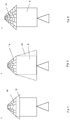
- FIG 1 a common spacecraft part such as an upper stage 1, in particular an upper liquid propulsion module of Ariane 6, carrying a launch vehicle adapter 2 is shown.
- the upper stage 1 has cylindrical part, in particular a cylindrical inter tank structure 4, a conical front side 6 and an aft side 8.
- the launch vehicle adapter 2 is positioned having the same conical shape as the front side 6.
- the front side 6 has a maximum outer diameter that is similar or equal, respectively, as the outer diameter of the cylindrical inter tank structure 4 such that the front side 6 does not projects over the cylindrical inter tank structure laterally.
- a central propulsion engine 10 is arranged which is used as driving means.
- the upper stage 1 can be equipped with a reusable kit 12 1 enabling the upper stage to re-entry into the atmosphere and to be reused for several missions according to the invention.
- the upper stage 1 is shown in a mission phase before separation of the launch vehicle adapter 2
- the upper stage 1 is shown in a mission phase after the separation of the launch vehicle adapter 2, ready for re-entry into the atmosphere.
- the kit 12 comprises heat shields 14 and, as shown in this embodiment, at least one decelerator 16 and optionally a parachute and/or parafoil system 17.
- the heat shields 14 protect the upper stage 1 against the high temperature which arise during the re-entry.
- the heat shields 14 are positioned under the launch vehicle adapter 2 which is held in place by a skirt 18 surrounding the cylindrical part 4 adjacent to the front side 6 of the upper stage 4. When the launch vehicle adapter 2 is separated, its skirt 18 is detached and the heat shields 14 are exposed. In addition, the deployment of the decelerator 16 is allowed. As will be explained in more detailed with reference to figure 7 , the heat shields 14 are supported by a support structure 19 which is attached to the upper stage cylinder 4 under the skirt 18.
- a preferred material for the heat shields 14 is Ceramic Matrix Composites (CMC), for instance High Temperature Ceramic Matrix Composites (HTCMC).
- CMC Ceramic Matrix Composites
- HTCMC High Temperature Ceramic Matrix Composites
- the heat shields 14 are non-ablative.
- the heat shields 14 are positioned on their support structure 19 (s. figure 7 ) between an outer surface of the front side 6 and the launch vehicle adapter 2. In this position, they are covered by the launch vehicle adapter 2 totally.
- the heat shields 14 form a kind of a conical panel extending nearly over the whole outer surface of the front side 6.
- the diameter of the heat shield panel is a bit smaller than the diameter of the cylindrical part 4 in order to allow an integration of the cylindrical part 4 that shifts the launch vehicle adapter 2 higher.
- the coverage of the outer diameter of the upper stage 1 and its sides is achieved with the decelerator 16. If the vehicle launch adapter 2 is separated, the heat shields 14, respectively the heat shields panel, cover the front side 6 on its outer surface.
- the at least one decelerator 16 or the decelerator system, respectively, is in its undeployed state in such a position at the aft side 8 that it protected against the high temperatures during the re-entry phase.
- the decelerator 16 is an inflatable aerodynamic decelerator and/or deployable aerodynamic decelerator.
- the basic function of the decelerator 16 is to reduce the ballistic coefficient if necessary or and/or to decelerate the upper stage 1 from high supersonic to subsonic. It would be deployed prior to reaching the re-entry interface so it would go through the high-enthalpy flow phases.
- the decelerator 16 is position at the aft side 8 within the outer diameter of the cylindrical inter tank structure 4.
- the decelerator means 16 is preferably deployed already in vacuum before the re-entry interface, helping to decelerate the stage from high supersonic to low supersonic speeds.
- the parachute and/or parafoil system 17 is also positioned at the aft side 8 of the upper stage 1. Exemplary, three parachutes 17a of the parachute and/or parafoil system 17 are shown. It can finally be deployed to slow the upper stage 1 down further. Further details of the parachute and/or parafoil system 17 are illustrated in figure 9 . As can be seen in figure 9 , a combination of both parachutes 17a and parafoils 17b is possible. Even ballutes 17c can be incorporated in the parachute and/or parafoil system 17.
- FIGS 4 and 5 further embodiments of a spacecraft part such as an upper stage 1 is shown.
- the at least one decelerator 16 is positioned at the front side 6 of the upper stage 1.
- the at least one decelerator 16 is configured to extend the conical shape of the front side 6 in its deployed state thereby surrounding the cylindrical inter tank structure 4 at least partially behind the front side 6.
- the deployed decelerator 16 extends at least over the entire axial length of the cylindrical inter tank structure 4 reaching to the aft side 8 or even beyond.
- the at least one decelerator 16 is in such position that it protected against the high temperatures during the re-entry phase.
- FIG 6 a further embodiment of a spacecraft part such as an upper stage 1 is shown. Contrary to embodiments shown before, a conical shaped front side 6 extends laterally over the cylindrical inter tank structure 4 of the upper stage 1.
- the upper stage 1 is also equipped with a reusable kit 12 according to the invention. For the sake of clarity, the reusable kit 12 is not illustrated.
- a not shown decelerator means 16, such as an inflatable aerodynamic decelerator and/or deployable aerodynamic decelerator, can be positioned at the front side 6 and/or at the aft side 8 as explained in the figures before.
- the diameter of a heat shields panel is increased in correspondence to the conical shaped front side 6. As the front side 6 extends laterally over the cylindrical inter tank structure 4, shadowing is provided against high-enthalpy flow.
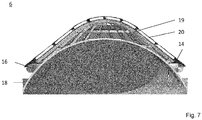
- Figure 7 illustrates how the heat shields 14 are supported on the front side 6 and where the decelerator means 16 is positioned in its undeployed state.
- the heat shields 14 are arranged to form a heat shield panel 19 covering the outer surface of the front side 6. They are carried by a support structure 19, corresponding to the conical shape of the front side 6.
- isolation elements 20 can be positioned under the heat shield panel, in particular between the heat shields 14 and the support structure 19. In order to create space for the undeployed decelerator 16, the heat shields 14 extends laterally over the support structure 19.
- the decelerator means 16 surrounds the support structure 19 and is positioned in the space between the heat shields 14 and the outer surface of the front end 6.
- the decelerator 16 is rolled up and when it is deployed it is getting unrolled continuing the conical shape of the heat shield panels (s. figure 4 and 6 ).
- the upper stage 1 after launch from a ground station such as Kourou and the separation of the reusable upper stage 1 and deployment of satellites, the upper stage 1 performs a deorbitation burn and reorients itself to align the heat shields 14 in the direction of the velocity vector.
- An inflatable aerodynamic decelerator 16 is then deployed at the preferred altitude of around 120 km prior to the point when aerodynamic forces dominate the capabilities of a reaction control system of the upper stage 1. Then the hypersonic, high enthalpy flow portion of the flight takes place, followed by deployment of a series of parachutes 16a. Eventually a parafoil 16b is deployed, and the upper stage begins its controlled flight towards the rendezvous point with the recovery aircraft, which then brings it back to the ground station.
- an attack angle ⁇ of zero is illustrated resulting in a ballistic entry.
- the angle of attack ⁇ is defined between the longitudinal axis of the upper stage 1 and relative flow direction of the atmosphere.
- the deployed decelerator means 16 and deployed parachutes 17a are shown in both states, undeployed and/or uninflated and deployed and/or inflated (dotted lines).
- a part 1 of a spacecraft for instance an upper stage, configured to re-entry into the atmosphere and to be reused for several missions, wherein the part 1 is equipped with a reusable kit comprising non-ablative heat shields 14, at least one decelerator means 16, and/or at least one parachute and/or parafoil system 17, a reusable kit 12 and a method to re-entry into the atmosphere.
- a reusable kit comprising non-ablative heat shields 14, at least one decelerator means 16, and/or at least one parachute and/or parafoil system 17, a reusable kit 12 and a method to re-entry into the atmosphere.
Landscapes
- Engineering & Computer Science (AREA)
- Remote Sensing (AREA)
- Aviation & Aerospace Engineering (AREA)
- Physics & Mathematics (AREA)
- Thermal Sciences (AREA)
- Health & Medical Sciences (AREA)
- Critical Care (AREA)
- Emergency Medicine (AREA)
- General Health & Medical Sciences (AREA)
- Details Of Aerials (AREA)
- Processing Of Solid Wastes (AREA)
Abstract
Description
- The present invention concerns to a spacecraft part such as an upper stage of a spacecraft, a kit enabling the re-entry of a spacecraft part such as an upper stage of a spacecraft, a method for re-entry of a spacecraft part for reuse and a use of a material.
- In the past, upper stages of spacecraft burnt up on re-entry into the atmosphere. In the meantime, the need arises for reusing upper stages such as the spacecraft Space Shuttle several years ago. However, the Space Shuttle re-entered into the atmosphere in a non-ballistic way using aerodynamic lifting properties of the vehicle shape for a re-entry at non-zero angle of attack (angle between the vehicle's longitudinal axis and the relative flow direction of the atmosphere). In order to enable a ballistic re-entry without using aerodynamic lift of the vehicle at an angle of attack of zero or almost zero, the re-entry temperatures are much higher so that the heat shields have to withstand higher temperatures. Well known are ablative materials for spacecraft heat shields, however, such heat shields are not reusable as the material is being removed during the re-entry.
- It is an object to the invention to provide a spacecraft part such that the upper stage can withstand the high temperatures at the re-entry into the atmosphere, to provide a reusable kit for enabling a spacecraft part such an upper stage to re-entry, to provide a method for re-entry of a spacecraft part such an upper stage for reuse, and to provide a use of Ceramic Matrix Composites (CMC).
- The object is solved by a spacecraft part according to the features of
claim 1, a kit according to the features ofclaim 2, a method for re-entry according to the features of claim 9 and a use of CMC according toclaim 10. Particular embodiments are disclosed in the dependent claims, in the description and in the figures. - According to the invention, a spacecraft part, for instance an upper stage, is configured to re-entry into the atmosphere and to be reused for several missions. The spacecraft part is equipped with reusable heat shields and at least one decelerator means. Preferably, the heat shields are of the non-ablative type and are made from Ceramic Matrix Composites (CMC), more preferably from Ultra High Temperature Ceramic Matrix Composites (UHTCM). The proposed solution allows the return of an upper (or other orbiting) rocket stage back to Earth safely and with a possibility of reuse. As an example, Ariane 6 Upper Liquid Propulsion Module can to be equipped with the reusable kit according to the invention. However, the invention could be applied on any other currently existing or in-development upper stage, either with reusable kit or as a part of baseline design. The possibility to extend the heat shields diameter past the diameter of the spacecraft part such as an upper stage cylinder shadows the rest of the vehicle from the high-enthalpy flow and allows to go without dedicated thermal protection anywhere except on the nose heat shields. Additionally, the CMCs, in particular UHTCMCs are an adequate material for control surfaces such as flaps and fins, which a priori experience greater heat fluxes than the rest of the vehicle. Here, higher thermal and geometrical stability during re-entry also provides more design freedom, than common ceramic matrix composites or ablative materials.
- In other words, the invention consists of spacecraft part such as an upper stage to be equipped with the reusable kit according to the invention. The reusable kit allows taking for instance, a current Ariane 6, upper stage, and by adding extra hardware with minimum modifications to existing design, safely return such upper stage back to Earth with the final goal to reuse it. Further on, not only the upper stage can be re-used, but at least the heat shields of the kit themselves.
- An inventive reusable Kit is to be installed on a spacecraft part provided to re-enter into the atmosphere, for instance an upper stage of a spacecraft, comprises non-ablative heat shields to be configured to withstands temperatures over 2000°C, in particular over 2500°C. Such temperatures normally arise in the phase of re-entry into the atmosphere. An exemplary material for the non-ablative heat shields are CMC, more preferably UHTCMC. Such material withstands the required temperatures and due to its non-ablative character, the kit can be reused for several missions without a replacement of the heat shields, respectively without any general replacement of the heat shields.
- Preferably, in order to fit the heat shields and their support structure, the kit has a support structure carrying the heat shields and holding them in place at the spacecraft part.
- In case a need for significant reduction of ballistic coefficient is identified, for instance for the deceleration from high supersonic to subsonic and controlled parafoil flight up to mid-air recovery, the kit can can additionally or separately comprise at least one decelerator means.
- The decelerator means is an inflatable aerodynamic decelerator or a deployable aerodynamic decelerator, for instance. The decelerator means is deployed already in vacuum before the re-entry interface. It helps decelerate the stage from high supersonic to low supersonic speeds.
- In the case that the center of pressure is required to be shifted more aft, the kit can additionally or separately comprise adequate steering means and or control means such as fins and/or flaps. Also, the decelerator can contribute to shifting the centre of pressure aft. In order to withstand the high temperature, it is preferred if an outer surface of the steering means and or control means are made from CMC or UHTCMC.
- In order to protect the decelerator means in its undeployed state against heat, for instance, if undeployed the decelerator means can surround the support structure carrying the heat shields and thereby being covered by the heat shields. In this state, the decelerator is an up rolled as a cylindrical roll, whereas if the decelerator is unrolled it forms a kind of umbrella surrounding the upper stage at least partially, for instance its cylindrical inter tank structure and/or its propulsion engine.
- Preferably, the decelerator means is of such material and design that it protects the upper stage at least partially against heat in its deployed state. By means of this, the decelerator continues the heat shields.
- According to the invention, a method of re-entry of a spacecraft part such as an upper stage of a spacecraft, comprises the step of re-entry into the atmosphere in an angle of attack α = 0 (zero) or almost zero. According to the invention, there is no need for additional hardware required for touchdown and terminal velocity reduction to zero (0), as it is performed by the helicopter, for instance. This reduces system complexity and costs.
- An exemplary flight sequence is as followed:
- 1. Normal operation of the Launcher system, including the deployment of the payload(s)
- 2. Separation of the upper part of the upper stage such as a launch vehicle adapter and exposure of the heat shields
- 3. Retro boost to begin the re-entry
- 4. Change of orientation to nose-first
- 5. Deployment of the decelerator
- 6. Re-entry and free fall
- 7. Optional: deployment of an inflatable aerodynamic decelerator and/or deployable aerodynamic decelerator and/or ballute
- 8. Flight through high-enthalpy phase
- 9. Deployment of parachutes sequence after reaching speeds below hypersonic (M<5)
- 10. Deployment of parafoil at subsonic
- 11. Capture with the helicopter
- 12. Return to manufacturing / integration site for refurbishment and eventual re-flight
- A preferred spacecraft part such an upper stage in order to realise this flight scenario is equipped with heat shields that have a thermal stability more than 2000°C, even more than 2500°C. An exemplary material is "conventional" CMC or UHTCMC which has a high thermal stability (>2500°C). The use of such material also allows the reusability of the heat shields. Such material is configured to manage the high enthalpy flow conditions and associated mechanical loads arising at the event of re-entry. In addition, it can be preferred if UHTCMC is used as an outer surface material for the spacecraft part. Besides heat shields, also steering and/or control surfaces can be made from UHTCMC.
- The use of UHTCMC enables the concept of a ballistically re-entering heavy vehicle, for instance at re-entry for instance but not limited to BC>10kg/m2, from orbital velocity. The use of such material also allows the reusability of the heat shields. Additionally, extremely high thermal stability (>2500°C) giving more design freedom for the heat shield design. The material may support a preferred the ballistic re-entry into the atmosphere and does not require any essential new architecture of the upper stage.
- Exemplary concepts, which are centered around the UHTCMC frontal heat shields are:
- Inflatable aerodynamic decelerator / deployable aerodynamic decelerator on the front side behind the UHTCMC heat shields
- ∘ Allows to further shadow the aft side of the vehicle
- ∘ Such aerodynamic decelerator / deployable aerodynamic decelerator would have an incidence angle to the flow smaller than that of the heat shields in order to be able to manage the high heat flux, while still providing shadowing
- ∘ It would also improve the static stability of the vehicle
- ∘ It would reduce the ballistic coefficient of the re-entry vehicle overall
- Aerodynamic decelerator / deployable aerodynamic decelerator ballute on the aft side
- ∘ It would also improve the static stability of the vehicle
- ∘ It would reduce the ballistic coefficient of the re-entry vehicle overall
- Fins / flaps as control surfaces or fixed
- ∘ To improve the static stability of the vehicle
- ∘ To allow controllability in hypersonic and supersonic flight
- Parachutes
∘ To reduce the speed of the vehicle from supersonic to subsonic - Parafoil
∘ To allow the vehicle to maneuver prior to mid-air capture by a helicopter - The reusable kit consists preferably of the following components:
- Ultra-High Temperature Ceramic Matrix Composite frontal heat shields (and its support structure), which may have a diameter such that it extends past the diameter of the upper stage to shadow the vehicle behind the heat shields
- Additional skirt under the Launch Vehicle Adaptor to allow accommodating the heat shields
- Parachutes & Parafoil systems and their fixations on the aft side
- Additionally, following optional hardware is foreseen in the kit:
- Fins / flaps on the aft side
- Inflatable aerodynamic decelerator (IAD) and/or deployable aerodynamic decelerator either on the front side directly behind the rigid front heat shields, or on the aft side
- Again, main features of the invention are:
- Reusable kit for an upper stage of a spacecraft, for instance the upper liquid propulsion module of
Ariane 6 - Re-use enables injection of micro satellites constellation in to Low Earth Orbit, as exemplary mission
- Ballistic, un-guided re-entry (α∼0° angle of attack, no active control)
- Mid-air retrieval (no landing legs, landing engines: empty upper stage is light enough)
- Recovery back to manufacturing / integration site for refurbishment and reuse
- A preferred kit includes:
- Additional skirt under the launch vehicle adapter
- heat shields made from CMC or UHTCMC and support structure
- Parachutes and parafoil systems and their fixations at the aft side.
- Optionally the kit can conclude:
- Fins / flaps, and/or
- Inflatable aerodynamic decelerator or deployable aerodynamic decelerator
- It is noted that the reusable kit can be adapted to other spacecraft parts in order to enable their re-entry. The use of the kit is not limited to an upper stage.
- In the following, preferred embodiments of the present invention are explained with respect to the accompanying drawings. As is to be understood, the various elements and components are depicted as examples only, may be facultative and/or combined in a manner different than that depicted. Reference signs for related elements are used comprehensively and are not defined again for each figure. Shown is schematically in
- Fig. 1
- an upper stage, for instance an upper liquid propulsion module of
Ariane 6 carrying a launch vehicle adapter, - Fig. 2
- a first embodiment of a reusable upper stage equipped with a reusable kit showing an undeployed and/or uninflated decelerator at the aft side,
- Fig. 3
- the first embodiment of an upper stage showing heat shields of the kit after separation of the launch vehicle adapter and the deployed and/or inflated decelerator,
- Fig. 4
- a second embodiment of an upper stage equipped with a reusable kit showing its deployed and/or inflated decelerator at the front side,
- Fig. 5
- a third embodiment of an upper stage equipped with a reusable kit showing a deployed and/or inflated decelerator at the front side,
- Fig. 6
- a fourth embodiment of an upper stage equipped with a reusable kit having an extending heat shields panel at the front side,
- Fig. 7
- a cross-sectional view of a preferred upper stage at its front side,
- Fig. 8
- a preferred mission profile,
- Fig. 9
- a preferred re-entry of the upper stage in free fall, and
- Fig. 10
- an illustration of the angle of attack.
- In
figure 1 , a common spacecraft part such as anupper stage 1, in particular an upper liquid propulsion module ofAriane 6, carrying alaunch vehicle adapter 2 is shown. - The
upper stage 1 has cylindrical part, in particular a cylindricalinter tank structure 4, a conicalfront side 6 and anaft side 8. At itsfront side 6, thelaunch vehicle adapter 2 is positioned having the same conical shape as thefront side 6. In particular, in the embodiment as illustrated infigure 1, 2 and 3 , thefront side 6 has a maximum outer diameter that is similar or equal, respectively, as the outer diameter of the cylindricalinter tank structure 4 such that thefront side 6 does not projects over the cylindrical inter tank structure laterally. At theaft side 8, acentral propulsion engine 10 is arranged which is used as driving means. - As shown in
figures 2 and 3 , theupper stage 1 can be equipped with areusable kit 12 1 enabling the upper stage to re-entry into the atmosphere and to be reused for several missions according to the invention. Infigure 2 , theupper stage 1 is shown in a mission phase before separation of thelaunch vehicle adapter 2, whereas infigure 3 theupper stage 1 is shown in a mission phase after the separation of thelaunch vehicle adapter 2, ready for re-entry into the atmosphere. - The
kit 12 comprisesheat shields 14 and, as shown in this embodiment, at least onedecelerator 16 and optionally a parachute and/orparafoil system 17. - The
heat shields 14 protect theupper stage 1 against the high temperature which arise during the re-entry. Theheat shields 14 are positioned under thelaunch vehicle adapter 2 which is held in place by askirt 18 surrounding thecylindrical part 4 adjacent to thefront side 6 of theupper stage 4. When thelaunch vehicle adapter 2 is separated, itsskirt 18 is detached and theheat shields 14 are exposed. In addition, the deployment of thedecelerator 16 is allowed. As will be explained in more detailed with reference tofigure 7 , theheat shields 14 are supported by asupport structure 19 which is attached to theupper stage cylinder 4 under theskirt 18. - A preferred material for the
heat shields 14 is Ceramic Matrix Composites (CMC), for instance High Temperature Ceramic Matrix Composites (HTCMC). In order to enable the reusability of thekit 12, theheat shields 14 are non-ablative. In the phase before re-entering into the atmosphere, theheat shields 14 are positioned on their support structure 19 (s.figure 7 ) between an outer surface of thefront side 6 and thelaunch vehicle adapter 2. In this position, they are covered by thelaunch vehicle adapter 2 totally. Theheat shields 14 form a kind of a conical panel extending nearly over the whole outer surface of thefront side 6. In this embodiment, the diameter of the heat shield panel is a bit smaller than the diameter of thecylindrical part 4 in order to allow an integration of thecylindrical part 4 that shifts thelaunch vehicle adapter 2 higher. The coverage of the outer diameter of theupper stage 1 and its sides is achieved with thedecelerator 16. If thevehicle launch adapter 2 is separated, theheat shields 14, respectively the heat shields panel, cover thefront side 6 on its outer surface. - The at least one
decelerator 16 or the decelerator system, respectively, is in its undeployed state in such a position at theaft side 8 that it protected against the high temperatures during the re-entry phase. Thedecelerator 16 is an inflatable aerodynamic decelerator and/or deployable aerodynamic decelerator. - The basic function of the
decelerator 16 is to reduce the ballistic coefficient if necessary or and/or to decelerate theupper stage 1 from high supersonic to subsonic. It would be deployed prior to reaching the re-entry interface so it would go through the high-enthalpy flow phases. - In the embodiment shown in
figure 2 , thedecelerator 16 is position at theaft side 8 within the outer diameter of the cylindricalinter tank structure 4. The decelerator means 16 is preferably deployed already in vacuum before the re-entry interface, helping to decelerate the stage from high supersonic to low supersonic speeds. - The parachute and/or
parafoil system 17 is also positioned at theaft side 8 of theupper stage 1. Exemplary, threeparachutes 17a of the parachute and/orparafoil system 17 are shown. It can finally be deployed to slow theupper stage 1 down further. Further details of the parachute and/orparafoil system 17 are illustrated infigure 9 . As can be seen infigure 9 , a combination of bothparachutes 17a and parafoils 17b is possible. Even ballutes 17c can be incorporated in the parachute and/orparafoil system 17. - In
figures 4 and 5 , further embodiments of a spacecraft part such as anupper stage 1 is shown. The main difference between the embodiments according tofigures 2 and 3 and the embodiment offigures 4 and 5 is that infigures 4 and 5 the at least onedecelerator 16 is positioned at thefront side 6 of theupper stage 1. Infigure 4 , the at least onedecelerator 16 is configured to extend the conical shape of thefront side 6 in its deployed state thereby surrounding the cylindricalinter tank structure 4 at least partially behind thefront side 6. Infigure 5 , the deployeddecelerator 16 extends at least over the entire axial length of the cylindricalinter tank structure 4 reaching to theaft side 8 or even beyond. In both embodiments according tofigure 4 and 5 , its undeployed and/or uninflated state, the at least onedecelerator 16 is in such position that it protected against the high temperatures during the re-entry phase. - In
figure 6 , a further embodiment of a spacecraft part such as anupper stage 1 is shown. Contrary to embodiments shown before, a conical shapedfront side 6 extends laterally over the cylindricalinter tank structure 4 of theupper stage 1. Theupper stage 1 is also equipped with areusable kit 12 according to the invention. For the sake of clarity, thereusable kit 12 is not illustrated. A not shown decelerator means 16, such as an inflatable aerodynamic decelerator and/or deployable aerodynamic decelerator, can be positioned at thefront side 6 and/or at theaft side 8 as explained in the figures before. - In order to effectively shadow the cylindrical,
inter tank structure 4 within an oscillation range when thedecelerator 16 is positioned at theaft side 8, the diameter of a heat shields panel is increased in correspondence to the conical shapedfront side 6. As thefront side 6 extends laterally over the cylindricalinter tank structure 4, shadowing is provided against high-enthalpy flow. -
Figure 7 illustrates how theheat shields 14 are supported on thefront side 6 and where the decelerator means 16 is positioned in its undeployed state. - The
heat shields 14 are arranged to form aheat shield panel 19 covering the outer surface of thefront side 6. They are carried by asupport structure 19, corresponding to the conical shape of thefront side 6. In addition,isolation elements 20 can be positioned under the heat shield panel, in particular between theheat shields 14 and thesupport structure 19. In order to create space for theundeployed decelerator 16, theheat shields 14 extends laterally over thesupport structure 19. - In its undeployed state, the decelerator means 16 surrounds the
support structure 19 and is positioned in the space between theheat shields 14 and the outer surface of thefront end 6. Thedecelerator 16 is rolled up and when it is deployed it is getting unrolled continuing the conical shape of the heat shield panels (s.figure 4 and 6 ). - For the sake of completeness, the
detachable skirt 18 holding thelaunch vehicle adapter 2 is illustrated. - In
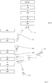
figures 8 and 9 , an ascent, flight, re-entry and recovery profile are described. On a mission profile level, following sequence can be foreseen: -
Figure 8 :- 1. Normal operation 100 of the Launcher system, including the deployment 110 of the payload(s)
- 2.
Separation 120 of the upper part of theupper stage 1 such as thelaunch vehicle adapter 2 and exposure of theheat shields 12 - 3.
Retro boost 140 to begin the re-entry - 4. Change of orientation to nose-first (front side 6) 160
- 5.
Deployment 180 of thedecelerator 16
-
Figure 9 :- 6. Re-entry and
free fall 200 - 7. Optional: deployment of
ballute 220 - 8. Flight through high-enthalpy phase
- 9. Deployment of
parachutes system 240 after reaching speeds below hypersonic (M<5) - 10. Deployment of parafoil at subsonic 260
- 11. Capture 280 with the
helicopter 22 - 12. Return 290 to site for refurbishment and re-flight
- 6. Re-entry and
- In other words, after launch from a ground station such as Kourou and the separation of the reusable
upper stage 1 and deployment of satellites, theupper stage 1 performs a deorbitation burn and reorients itself to align theheat shields 14 in the direction of the velocity vector. An inflatableaerodynamic decelerator 16 is then deployed at the preferred altitude of around 120 km prior to the point when aerodynamic forces dominate the capabilities of a reaction control system of theupper stage 1. Then the hypersonic, high enthalpy flow portion of the flight takes place, followed by deployment of a series of parachutes 16a. Eventually a parafoil 16b is deployed, and the upper stage begins its controlled flight towards the rendezvous point with the recovery aircraft, which then brings it back to the ground station. - In
figure 10 , an attack angle α of zero is illustrated resulting in a ballistic entry. The angle of attack α is defined between the longitudinal axis of theupper stage 1 and relative flow direction of the atmosphere. In addition, the deployed decelerator means 16 and deployedparachutes 17a are shown in both states, undeployed and/or uninflated and deployed and/or inflated (dotted lines). - Disclosed is a
part 1 of a spacecraft, for instance an upper stage, configured to re-entry into the atmosphere and to be reused for several missions, wherein thepart 1 is equipped with a reusable kit comprisingnon-ablative heat shields 14, at least one decelerator means 16, and/or at least one parachute and/orparafoil system 17, areusable kit 12 and a method to re-entry into the atmosphere. -
- 1
- spacecraft part, here: upper stage
- 2
- launch vehicle adapter, here: upper part
- 4
- cylindrical part, here: inter tank structure
- 6
- front side
- 8
- aft side
- 10
- engine
- 12
- kit
- 14
- heat shield
- 16
- decelerator means, in particular inflatable aerodynamic decelerator and/or deployable aerodynamic decelerator
- 17
- parachute and/or parafoil system
- 17a
- parachute
- 17b
- parafoil
- 17c
- ballute
- 18
- skirt
- 19
- support structure
- 20
- isolation elements
- 22
- helicopter
- 100
- normal operation of a launcher system
- 110
- deployment of the payload
- 120
- separation of upper part
- 140
- retro-boost
- 160
- change of orientation
- 180
- deployment of decelerator
- 200
- re-entry
- 120
- deployment of ballute
- 240
- deployment of parachute system
- 260
- deployment of parafoil system
- 280
- capture
- 290
- return to side
- X
- longitudinal axis of the upper stage
- α
- angle of attack
Claims (10)
- Part (1) of a spacecraft, for instance an upper stage, configured to re-entry into the atmosphere and to be reused for several missions, wherein the part (1) is equipped with reusable heat shields (14) and at least one decelerator means (16).
- Kit (12) to be installed on a spacecraft part (1) provided to re-enter into the atmosphere, for instance an upper stage of a spacecraft, comprising non-ablative heat shields (12) to be configured to withstands temperatures over 2000°C, in particular over 2500°C
- Kit according to claim 2, having a support structure (19) for holding the heat shields (14) in place at the spacecraft part (1).
- Kit according to claim 2 or 3, further comprising at least one decelerator means (16).
- Kit according to claim 4, wherein the decelerator means (16) is an inflatable aerodynamic decelerator and/or deployable aerodynamic decelerator (16).
- Kit according to claims 4 and 5, wherein in its deployed state the decelerator means (16) protects the upper stage (1) at least partially against heat.
- Kit according to claim 4, 5 or 6, wherein in its undeployed state the decelerator means (16) surrounds the support structure (19) carrying the heat shields (14), thereby being covered by the heat shields (14).
- Kit according to any of the preceding claims, further comprising steering means and/or control surfaces.
- Method of re-entry of a spacecraft part (1) such as an upper stage of a spacecraft, wherein the spacecraft part (1) re-enters into the atmosphere in an angle of attack α = 0 (zero) or almost zero.
- Using CMC, in particular UHTCMC, for a spacecraft or for a spacecraft part (1) as an outer surface material in order to enable ballistic re-entry into the atmosphere.
Applications Claiming Priority (1)
| Application Number | Priority Date | Filing Date | Title |
|---|---|---|---|
| DE102019130591 | 2019-11-13 |
Publications (2)
| Publication Number | Publication Date |
|---|---|
| EP3822177A2 true EP3822177A2 (en) | 2021-05-19 |
| EP3822177A3 EP3822177A3 (en) | 2021-07-21 |
Family
ID=73401404
Family Applications (1)
| Application Number | Title | Priority Date | Filing Date |
|---|---|---|---|
| EP20207215.3A Pending EP3822177A3 (en) | 2019-11-13 | 2020-11-12 | Reusable part of a spacecraft and reusable kit |
Country Status (1)
| Country | Link |
|---|---|
| EP (1) | EP3822177A3 (en) |
Cited By (3)
| Publication number | Priority date | Publication date | Assignee | Title |
|---|---|---|---|---|
| CN109737827A (en) * | 2019-02-25 | 2019-05-10 | 北京星际荣耀空间科技有限公司 | A kind of aerodynamic decelerator device and sub- level structure |
| CN115743629A (en) * | 2022-11-08 | 2023-03-07 | 北京空间机电研究所 | Global rapid positioning detection system and method |
| WO2023096820A3 (en) * | 2021-11-17 | 2023-10-26 | Outpost Technologies Corporation | Space vehicles with paraglider re-entry, and associated systems and methods |
Citations (4)
| Publication number | Priority date | Publication date | Assignee | Title |
|---|---|---|---|---|
| US3250499A (en) * | 1964-05-20 | 1966-05-10 | Martin Marietta Corp | Hypersonic drag device |
| US4832288A (en) * | 1987-07-23 | 1989-05-23 | Aerospace Recovery System, Inc. | Recovery system |
| JPH04163300A (en) * | 1990-10-24 | 1992-06-08 | Natl Space Dev Agency Japan<Nasda> | Recovery type spacecraft |
| CN109455318A (en) * | 2018-10-11 | 2019-03-12 | 北京空间机电研究所 | A kind of gas-filled unfolded re-entry deceleration system |
Family Cites Families (4)
| Publication number | Priority date | Publication date | Assignee | Title |
|---|---|---|---|---|
| US3286951A (en) * | 1963-09-27 | 1966-11-22 | Douglas Aircraft Co Inc | Recovery system |
| US10081446B2 (en) * | 2015-03-11 | 2018-09-25 | William C. Stone | System for emergency crew return and down-mass from orbit |
| CN104986358B (en) * | 2015-06-24 | 2017-01-04 | 西北工业大学 | The steady Inflatable re-entry vehicle of a kind of increasing |
| CN110116823B (en) * | 2019-04-19 | 2020-08-18 | 北京星际荣耀空间科技有限公司 | A recyclable and reusable solid launch vehicle substage |
-
2020
- 2020-11-12 EP EP20207215.3A patent/EP3822177A3/en active Pending
Patent Citations (4)
| Publication number | Priority date | Publication date | Assignee | Title |
|---|---|---|---|---|
| US3250499A (en) * | 1964-05-20 | 1966-05-10 | Martin Marietta Corp | Hypersonic drag device |
| US4832288A (en) * | 1987-07-23 | 1989-05-23 | Aerospace Recovery System, Inc. | Recovery system |
| JPH04163300A (en) * | 1990-10-24 | 1992-06-08 | Natl Space Dev Agency Japan<Nasda> | Recovery type spacecraft |
| CN109455318A (en) * | 2018-10-11 | 2019-03-12 | 北京空间机电研究所 | A kind of gas-filled unfolded re-entry deceleration system |
Cited By (7)
| Publication number | Priority date | Publication date | Assignee | Title |
|---|---|---|---|---|
| CN109737827A (en) * | 2019-02-25 | 2019-05-10 | 北京星际荣耀空间科技有限公司 | A kind of aerodynamic decelerator device and sub- level structure |
| CN109737827B (en) * | 2019-02-25 | 2024-04-19 | 北京星际荣耀空间科技股份有限公司 | Pneumatic speed reducer and sub-level structure |
| WO2023096820A3 (en) * | 2021-11-17 | 2023-10-26 | Outpost Technologies Corporation | Space vehicles with paraglider re-entry, and associated systems and methods |
| GB2626504A (en) * | 2021-11-17 | 2024-07-24 | Outpost Tech Corporation | Space vehicles with paraglider re-entry, and associated systems and methods |
| JP2024543090A (en) * | 2021-11-17 | 2024-11-19 | アウトポスト テクノロジーズ コーポレーション | Space vehicle with paraglider re-entry capability and related systems and methods - Patents.com |
| US12509252B2 (en) | 2021-11-17 | 2025-12-30 | Outpost Technologies Corporation | Space vehicles with paraglider re-entry, and associated systems and methods |
| CN115743629A (en) * | 2022-11-08 | 2023-03-07 | 北京空间机电研究所 | Global rapid positioning detection system and method |
Also Published As
| Publication number | Publication date |
|---|---|
| EP3822177A3 (en) | 2021-07-21 |
Similar Documents
| Publication | Publication Date | Title |
|---|---|---|
| US6666409B2 (en) | Crewed on-orbit, returnable, and reusable space vehicle | |
| US4901949A (en) | Rocket-powered, air-deployed, lift-assisted booster vehicle for orbital, supraorbital and suborbital flight | |
| EP2662288B1 (en) | Small launch vehicle | |
| US4896847A (en) | Aerodynamic braking system for recovering a space vehicle | |
| US4796839A (en) | Space launch vehicle | |
| US20070012820A1 (en) | Reusable upper stage | |
| US4471926A (en) | Transfer vehicle for use in conjunction with a reusable space shuttle | |
| Ragab et al. | Launch vehicle recovery and reuse | |
| US6921051B2 (en) | System for the delivery and orbital maintenance of micro satellites and small space-based instruments | |
| US20240391611A1 (en) | Satellite launch system | |
| US3700193A (en) | A method of delivering a vehicle to earth orbit and returning the reusable portion thereof to earth | |
| US3576298A (en) | Aerospace vehicle | |
| WO1986001484A1 (en) | Satelite transfer vehicle | |
| US6817580B2 (en) | System and method for return and landing of launch vehicle booster stage | |
| US20240010360A1 (en) | Reusable space transportation system | |
| US6068211A (en) | Method of earth orbit space transportation and return | |
| US11565833B2 (en) | Recovery of a final stage of a spacecraft launch vehicle | |
| US12187460B2 (en) | Reusable part of a spacecraft and reusable kit with non-ablative heat shields | |
| US20230150700A1 (en) | Space vehicles with paraglider re-entry, and associated systems and methods | |
| US3001739A (en) | Aerial capsule emergency separation device | |
| EP4117993A1 (en) | Launch system and method | |
| US5158248A (en) | Modular earth-return space vehicle | |
| Heinrich | GreenSpace and reuse scenarios for launcher industry | |
| STEINCAMP | Future civil space program logistics | |
| Elliot et al. | NEPTranS: a shuttle-tended NEP interplanetary transporation system |
Legal Events
| Date | Code | Title | Description |
|---|---|---|---|
| PUAI | Public reference made under article 153(3) epc to a published international application that has entered the european phase |
Free format text: ORIGINAL CODE: 0009012 |
|
| STAA | Information on the status of an ep patent application or granted ep patent |
Free format text: STATUS: THE APPLICATION HAS BEEN PUBLISHED |
|
| AK | Designated contracting states |
Kind code of ref document: A2 Designated state(s): AL AT BE BG CH CY CZ DE DK EE ES FI FR GB GR HR HU IE IS IT LI LT LU LV MC MK MT NL NO PL PT RO RS SE SI SK SM TR |
|
| PUAL | Search report despatched |
Free format text: ORIGINAL CODE: 0009013 |
|
| AK | Designated contracting states |
Kind code of ref document: A3 Designated state(s): AL AT BE BG CH CY CZ DE DK EE ES FI FR GB GR HR HU IE IS IT LI LT LU LV MC MK MT NL NO PL PT RO RS SE SI SK SM TR |
|
| RIC1 | Information provided on ipc code assigned before grant |
Ipc: B64G 1/58 20060101AFI20210611BHEP Ipc: B64G 1/62 20060101ALI20210611BHEP |
|
| STAA | Information on the status of an ep patent application or granted ep patent |
Free format text: STATUS: REQUEST FOR EXAMINATION WAS MADE |
|
| 17P | Request for examination filed |
Effective date: 20211006 |
|
| RBV | Designated contracting states (corrected) |
Designated state(s): AL AT BE BG CH CY CZ DE DK EE ES FI FR GB GR HR HU IE IS IT LI LT LU LV MC MK MT NL NO PL PT RO RS SE SI SK SM TR |
|
| STAA | Information on the status of an ep patent application or granted ep patent |
Free format text: STATUS: EXAMINATION IS IN PROGRESS |
|
| 17Q | First examination report despatched |
Effective date: 20220817 |
|
| P01 | Opt-out of the competence of the unified patent court (upc) registered |
Effective date: 20230612 |