EP3822118B1 - A hooklift arrangement, a vehicle, and a method in relation thereto - Google Patents
A hooklift arrangement, a vehicle, and a method in relation thereto Download PDFInfo
- Publication number
- EP3822118B1 EP3822118B1 EP19209691.5A EP19209691A EP3822118B1 EP 3822118 B1 EP3822118 B1 EP 3822118B1 EP 19209691 A EP19209691 A EP 19209691A EP 3822118 B1 EP3822118 B1 EP 3822118B1
- Authority
- EP
- European Patent Office
- Prior art keywords
- vehicle
- load carrying
- carrying object
- operation mode
- cylinder
- Prior art date
- Legal status (The legal status is an assumption and is not a legal conclusion. Google has not performed a legal analysis and makes no representation as to the accuracy of the status listed.)
- Active
Links
Images


Classifications
-
- B—PERFORMING OPERATIONS; TRANSPORTING
- B60—VEHICLES IN GENERAL
- B60P—VEHICLES ADAPTED FOR LOAD TRANSPORTATION OR TO TRANSPORT, TO CARRY, OR TO COMPRISE SPECIAL LOADS OR OBJECTS
- B60P1/00—Vehicles predominantly for transporting loads and modified to facilitate loading, consolidating the load, or unloading
- B60P1/64—Vehicles predominantly for transporting loads and modified to facilitate loading, consolidating the load, or unloading the load supporting or containing element being readily removable
- B60P1/6418—Vehicles predominantly for transporting loads and modified to facilitate loading, consolidating the load, or unloading the load supporting or containing element being readily removable the load-transporting element being a container or similar
- B60P1/6427—Vehicles predominantly for transporting loads and modified to facilitate loading, consolidating the load, or unloading the load supporting or containing element being readily removable the load-transporting element being a container or similar the load-transporting element being shifted horizontally in a fore and aft direction, combined or not with a vertical displacement
-
- F—MECHANICAL ENGINEERING; LIGHTING; HEATING; WEAPONS; BLASTING
- F15—FLUID-PRESSURE ACTUATORS; HYDRAULICS OR PNEUMATICS IN GENERAL
- F15B—SYSTEMS ACTING BY MEANS OF FLUIDS IN GENERAL; FLUID-PRESSURE ACTUATORS, e.g. SERVOMOTORS; DETAILS OF FLUID-PRESSURE SYSTEMS, NOT OTHERWISE PROVIDED FOR
- F15B2211/00—Circuits for servomotor systems
- F15B2211/60—Circuit components or control therefor
- F15B2211/665—Methods of control using electronic components
-
- F—MECHANICAL ENGINEERING; LIGHTING; HEATING; WEAPONS; BLASTING
- F15—FLUID-PRESSURE ACTUATORS; HYDRAULICS OR PNEUMATICS IN GENERAL
- F15B—SYSTEMS ACTING BY MEANS OF FLUIDS IN GENERAL; FLUID-PRESSURE ACTUATORS, e.g. SERVOMOTORS; DETAILS OF FLUID-PRESSURE SYSTEMS, NOT OTHERWISE PROVIDED FOR
- F15B2211/00—Circuits for servomotor systems
- F15B2211/70—Output members, e.g. hydraulic motors or cylinders or control therefor
- F15B2211/705—Output members, e.g. hydraulic motors or cylinders or control therefor characterised by the type of output members or actuators
- F15B2211/7051—Linear output members
- F15B2211/7053—Double-acting output members
Definitions
- the present disclosure relates to a hooklift arrangement, a vehicle, and a method in relation thereto, that particularly are configured to improve operation when loading a load carrying object to the vehicle.
- a vehicle may be equipped with different working equipment, such as a hooklift (also called a demountable), to perform certain working tasks such as loading and unloading of objects to and from the vehicle.
- a hooklift also called a demountable
- the vehicle may load and unload various load carrying objects like flatracks, dumpster bodies, and similar containers.
- Various applications within waste-handling, recycling, scrap and demolition industries are then available.
- the hooklift comprises a hydraulic system usually comprising one or two double-acting lifting cylinders operating the loading and the unloading of load carrying objects.
- the lifting cylinder(s) are used to position the hook in relation to the load carrying object and further to lift and pull the load onto the truck during loading and also to lift and push it off the truck during unloading.
- the vehicle is positioned such that the longitudinal axis of the truck essentially is aligned with the longitudinal axis of the load carrying object to be loaded.
- the hooklift is then lowered from the parked position to an operation position and the hook on the hooklift is engaged with a bar, or other type of connection means, on the load carrying object.
- the lifting cylinder(s) of the hooklift is activated such that it lifts one end of the load carrying object and pulls it onto rollers on the back of the truck until it is in a loaded position on the truck and ready for transport to a new position.
- US4911318A discloses a vehicle provided with a hooklift structured to be attached to one end of a flatrack in order to lift it up. To avoid dragging the flatrack across the ground, the vehicle is put into reverse and backed up whilst the lifthook is retracted. The flatrack then moves on vehicle-mounted skid plates.
- US4153169A discloses a vehicle mounted with a lifter mechanism that lifts one end of a container to let the vehicle back into the space beneath the container, and the container can then be lowered onto the vehicle bed.
- the lifter mechanism is mounted to a horizontally movable carriage on the vehicle bed. During reverse motion the carriage is motionless.
- US20160016500A1 discloses how a truck provided with a winch raises a tank from horizontal to vertical by backing up the truck.
- US10131264A1 discloses a similar vehicle-mounted hooklift construction that uses a single cylinder.
- EP2570301 discloses a method for lowering a tipping frame of a hooklift which requires very little energy.
- a problem with the current loading sequence is that it is relatively slow, due to the capacity of the hydraulic system operating the lifting cylinder in combination with the, normally quite heavy, load carrying object. Further, the presently applied loading sequence requires quite a lot of energy for driving the loading movements of the lifting cylinders.
- An object of the present invention is to achieve a hooklift arrangement, a vehicle, and a method that eliminates, or at least mitigates, the above problems with the presently used technique.
- a first aspect of the present invention relates a hooklift arrangement (2) for loading a load carrying object (4) onto a vehicle (6), and structured to be mounted to the vehicle.
- the hooklift arrangement (2) comprising:
- the control system (20) is configured to, during loading of a load carrying object (4), determine, based upon the position signal (18), that a predetermined part (24) of the load carrying object (4) has been lifted higher than a predetermined level L being defined for passive operation mode of the cylinder (14), and, in response to that the load carrying object (4) has been lifted higher than said predetermined level L, the control system (20) is further configured to generate control signals (22) for changing the operation mode of the cylinder (14) from an active operation mode to a passive operation mode, and to the vehicle (6) for moving the vehicle (6) towards the load carrying object (4), such that said movement of the vehicle (6) moves the load carrying object (4) on to the vehicle (6).
- the control system (20) is further configured to evaluate the position of the load carrying object (4) in relation to the vehicle (6), and to compare the position to a predetermined position in relation to the vehicle (6), and wherein, when the load carrying object (4) has reached said predetermined position, the control system (20) is configured to change operation mode of the cylinder (14) from the passive operation mode to the active operation mode and finish the loading of the load carrying object (4).
- This mode of operation change is advantageous in order to smoothly finish the loading procedure.
- a second aspect of the present invention relates to a vehicle comprising a hooklift arrangement.
- the vehicle is provided with essentially the corresponding features as been described above.
- a third aspect of the present invention relates to a method of a hooklift arrangement, or of a vehicle.
- the hooklift arrangement and the vehicle are described above.
- the method comprises:
- the method comprises:
- the loading is done faster in comparison to the presently applied loading procedures.
- the loading time can be shortened considerably by actively controlling the loading by moving the vehicle in a reverse direction instead of actively using the hooklift for lifting, i.e. the lifting cylinder is set in a passive operation mode.
- the lifting cylinder is set in a passive operation mode.
- the vehicle may be used in up to approximately 2/3 of the total loading operation this offer a considerable reduction in the total time required for loading.
- the loading is further done in a more energy efficient manner.
- the invention is based on a loading sequence where the vehicle is not only used to position the hooklift next to the load carrying object, but also to actively take part when the load carrying object is loaded onto the vehicle.
- the invention may be implemented as an assisted loading process, where instructions for a driver of the hooklift vehicle is generated. Further, the invention may of course also be implemented as an autonomous loading process, where instructions directly applied to the hooklift and/or the vehicle are generated. Some steps of the loading process may further be performed autonomously where as other steps are performed by assisting the driver of the hooklift vehicle with instructions.
- a hooklift arrangement 2 is provided for loading a load carrying object 4 onto a vehicle 6.
- the load carrying object 4 may e.g. be flatracks, dumpster bodies, and similar containers.
- the hooklift arrangement is structured to be mounted to the vehicle.
- the hooklift arrangement 2 comprises a movable arm 8 arranged to pivot around an axis parallel to the plane of the chassis of the vehicle, from a first position, where a first engagement member 10, e.g. a hook, attached to the movable arm 8, is structured to be engaged to a second engagement member 12, e.g. a bar or similar, attached to the load carrying object 4, to a second position, corresponding to a position where an engaged load carrying object 4 is fully loaded on to the vehicle 6.
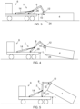
- the first position is illustrated in figure 3 and the second position is illustrated in figure 8 where the load carrying object is loaded onto the vehicle.
- the hooklift arrangement further comprises at least one hydraulic double-acting cylinder 14 attached to the movable arm 8, and the cylinder 14 being operable in an active operation mode, wherein the piston rod of the cylinder controls the movement of the movable arm 8, and in a passive operation mode, wherein the movable arm 8 controls the movement of the piston rod of the cylinder 14.
- the hydraulics of the double-acting cylinder 14 is set to be in a so-called regenerative mode wherein the respective piston chamber and the piston rod chamber of the cylinder 14 are interconnected and in further connection with a tank of the hydraulic system through e.g. flow control valves.
- the flow control valves may be used to control the return flow to tank from the cylinder(s).
- the hooklift arrangement also comprises a sensor system 16 configured to determine positions of the movable arm 8 and/or the load carrying object 4 in relation to the vehicle 6, and to determine a position signal 18 in dependence thereto.
- the sensor system may comprise a plurality of different sensors arranged on the movable arm or otherwise on the hooklift arrangement, and/or sensors arranged on the vehicle.
- the determined position signal 18 may be generated from a single sensor unit or result from a plurality of sensor signals generated by a plurality of sensor units. Different types of sensors applicable herein will be further discussed below.
- a control system 20 is also provided configured to receive the position signal 18, and to determine and generate control signals 22 controlling the operation of the cylinder 14, and of the vehicle 6.
- the control system 20 may comprise one or more processing units to support the determination and generation of control signals 22 for the controlling the operation of the hooklift 2 and vehicle 6.
- the control system may be decentralized, i.e. divided into several sub-control units, and is provided with one or many memory units. It is also provided with communication capabilities, both via physical connections and/or wireless connections.
- the control system 20 is configured to, during loading of a load carrying object 4, determine, based upon the position signal 18, that a predetermined part 24 of the load carrying object 4 has been lifted higher than a predetermined level L being defined for passive operation mode of the cylinder 14.
- the predetermined level L is related to the dimensions of the vehicle and the load carrying object. The predetermined level L may be determined based on the specific load carrying object to be loaded or be set to a default value adapted to a generic load carrying object.
- control system 20 is further configured to generate control signals 22 for changing the operation mode of the cylinder 14 from an active operation mode to a passive operation mode, and to the vehicle 6 for moving the vehicle 6 towards the load carrying object 4, such that said movement of the vehicle 6 moves the load carrying object 4 on to the vehicle 6.
- control signals 22 for changing the operation mode of the cylinder 14 from an active operation mode to a passive operation mode, and to the vehicle 6 for moving the vehicle 6 towards the load carrying object 4, such that said movement of the vehicle 6 moves the load carrying object 4 on to the vehicle 6.
- the vehicle moves to the left in the figure.
- the vehicle and/or hooklift is typically equipped with sensors detecting moving and nonmoving objects, including the load carrying object to be loaded and the environment at least partly surrounding the vehicle.
- sensors detecting moving and nonmoving objects, including the load carrying object to be loaded and the environment at least partly surrounding the vehicle.
- sensors are LIDAR, 3D Cam, Cameras, Lasers, thermal cameras and radars.
- Common for these type of sensors is that they image or describe the surroundings with image data.
- Image data in this aspect being data organized in a matrix to describe the spatial relationship of the surrounding with respect to what the sensors are measuring.
- various sensors for gathering information about the current state of the vehicle and hooklift as well as its surrounding are available. Some examples of these are pressure sensors in the lifting cylinder of the hooklift, sensors for estimating the weight of the load carrying object, the center of mass of the load carrying object etc. Other sensors, like sensors for measuring a tilting angle or position of a part of the hooklift in relation to a reference point, may be used to estimate the angle of the hooklift arm and hence also the location of the arm and a load carrying object engaged to the hook of the arm.
- An operation instruction in the control signal 22 may be an instruction for any type of movement of the hooklift or vehicle, or sequence of movements. It may e.g. be for driving the vehicle in forward direction or in reverse, activating the breaks of the vehicle, or for lowering or raising the hook of the hooklift.
- the operation instructions are managed and generated by the control system(s) of the vehicle and/or hooklift.
- the control system of the hooklift and the control system of the vehicle are communicating and the control system of the hooklift may generate and communicate driving instructions for the vehicle to the control system of the vehicle, and vice versa.
- the control system is also configured to determine and generate control signals applicable both if the vehicle and/or hooklift is semi-automatically and/or automatically operated. In the semi-automatic operation the control signal may be determined in dependence of instructions generated by an operator.
- the predetermined level L defined for change to passive operation mode of the cylinder is a level where a lower edge 24 of a lifted part of the load carrying object 4 is above the level of the plane of a loading part 26 of the vehicle 6 whereto the load carrying object 4 is to be loaded, and wherein during movement of the vehicle 6 the loading part 26 moves below at least a part of the load carrying object 4.
- control system 20 is further configured to, during the movement of the vehicle 6 towards the load carrying object 4, evaluate the position of the load carrying object 4 in relation to the vehicle 6, and to compare the position to a predetermined position in relation to the vehicle 6.
- control system 20 is configured to change operation mode of the cylinder 14 from the passive operation mode to the active operation mode and finish the loading of the load carrying object 4.
- the predetermined position of the load carrying object 4 for change to active operation mode of the cylinder 14 is preferably a position where the load carrying object 4 is about to completely leave the ground, which is illustrated in figure 6 and in figure 7 the load carrying object 4 has completely left the ground.
- the position indicating that the load carrying object 4 is about to completely leave the ground is defined by one or many of the angle of the movable arm 8, image data depicting the load carrying object 4 and its position relative to the ground, and the relative position of the load carrying object 4 to a reference point on the vehicle 6 such as rear rollers.
- Rear rollers may be provided on the back edge of the loading part 26 of the vehicle on which rollers the load carrying object rolls during the loading procedure.
- the position of the load carrying object and then changing of the mode may also be indirectly determined by monitoring the pressures/forces of the hydraulic cylinder(s).
- the control system may for example then determine pressure values when it is safe and possible to change from active to passive mode and also to determine the position when the load carrying object is hitting the rollers and starts to leave the ground.
- Operational mode changes may also be based upon cylinder force by using passive mode when the forces are on levels where the vehicle has the possibility to perform the loading sequence. It would then be possible to combine cylinder position and speed monitoring such that the control system is adapted to apply the fastest and/or most economic loading sequence.
- the present invention also relates to a vehicle 6 comprising a hooklift arrangement 2 for loading a load carrying object onto the vehicle, where the hooklift arrangement 2 is structured to be mounted to the vehicle 6.
- the vehicle will also be described with references to figures 3-8 .
- the following description of the vehicle is similar to the above description of the hooklift arrangement and it is also referred to that description if applicable.
- the vehicle comprises a movable arm 8 arranged to pivot around an axis parallel to the plane of the chassis of the vehicle 6, from a first position, where a first engagement member 10, attached to the movable arm 8, is structured to be engaged to a second engagement member 12 attached to the load carrying object 4, to a second position, corresponding to a position where an engaged load carrying object 4 is fully loaded on to the vehicle 6.
- At least one hydraulic double-acting cylinder 14 is provided and is attached to the movable arm 8.
- the cylinder 14 is operable in an active operation mode, wherein the piston rod of the cylinder controls the movement of the movable arm 8, and in a passive operation mode, wherein the movable arm 8 controls the movement of the piston rod of the cylinder.
- the vehicle 6 further comprises a sensor system 16 configured to determine positions of the movable arm 8 and/or the load carrying object 4 in relation to the vehicle 6, and to determine a position signal 18 in dependence thereto.
- the sensor system may comprise a plurality of different sensors arranged e.g. at the movable arm or at the vehicle. Examples of applicable sensors are given above in relation to the description of the hooklift arrangement.
- the vehicle further comprises a control system 20 configured to receive the position signal 18, and to determine and generate control signals 22 controlling the operation of the cylinder 14, and of the vehicle 6.
- the control system 20 may comprise one or more processing units to support the determination and generation of control signals 22 for the controlling the operation of the hooklift 2 and vehicle 6.
- the control system may be decentralized, i.e. divided into several sub-control units, and provided with one or many memory units. It is also provided with communication capabilities, both via physical connections and/or wireless connections.
- the control system 20 is configured to, during loading of a load carrying object 4, determine, based upon the position signal 18, that a predetermined part 24 of the load carrying object 4 has been lifted higher than a predetermined level L being defined for passive operation mode of the cylinder 14. In response to that the load carrying object 4 has been lifted higher than the predetermined level L, the control system 20 is further configured to generate control signals 22 for changing the operation mode of the cylinder 14 from an active operation mode to a passive operation mode, and to the vehicle 6 for moving the vehicle towards the load carrying object 4, such that the movement of the vehicle 6 moves the load carrying object 4 on to the vehicle.
- the predetermined level L defined for change to passive operation mode of the cylinder 4 is a level where a lower edge 24 of a lifted part of the load carrying object 4 is above the level of the plane of a loading part 26 of the vehicle 6 whereto the load carrying object 4 is to be loaded. During movement of the vehicle 6 the loading part 26 moves below the load carrying object 4.
- control system 20 is further configured to evaluate the position of the load carrying object 4 in relation to the vehicle.
- the control system then is configured to compare the position to a predetermined position in relation to the vehicle 6, and wherein, when the load carrying object 4 has reached the predetermined position, the control system 20 is configured to change operation mode of the cylinder 14 from the passive operation mode to the active operation mode and finish the loading of the load carrying object 4.
- the predetermined position of the load carrying object 4 for change to active operation mode of the cylinder 14 is preferably a position where the load carrying object 4 is about to completely leave the ground.
- the position indicating that the load carrying object 4 is about to completely leave the ground is defined by one or many of the angle of the movable arm 8, image data depicting the load carrying object 4 and its position relative to the ground, and the relative position of the load carrying object 4 to a reference point on the vehicle 6 such as rear rollers.
- the positions of the movable arm 8 may be determined by determining a pivoting angle of the movable arm.
- the hydraulics of the double-acting cylinder 14 is set to be in a regenerative mode wherein a respective piston chamber and a piston rod chamber of the cylinder are interconnected and in further connection with a tank of the hydraulic system through e.g. flow control valves.
- the present invention also relates to a method of a hooklift arrangement or of a vehicle comprising a hooklift arrangement.
- a method is provided of a hooklift arrangement 2 for loading a load carrying object 4 onto a vehicle 6, and structured to be mounted to the vehicle, or a method is provided of a vehicle 6 comprising a hooklift arrangement 2.
- the hooklift arrangement 2 comprises a movable arm 8, at least one hydraulic double-acting cylinder 14 attached to the movable arm, a sensor system 16 and a control system 20.
- the method comprises:
- the method further comprises that the predetermined level L defined for change to passive operation mode of the cylinder, is a level where a lower edge 24 of a lifted part of the load carrying object is above the level of the plane of a loading part 26 of the vehicle whereto the load carrying object is to be loaded. During movement of the vehicle the loading part moves below the load carrying object.
- the method comprises, during the movement of the vehicle towards the load carrying object:
- Figure 3 shows that the first engagement member 10 of the hooklift has been attached to the second engagement member 12 of the load carrying object 4.
- Figure 4 shows that the loading has started by operating the cylinder(s) inwards; the truck is in neutral gear and handbrake is released, and the part of the load carrying object closest the vehicle is lifted and the opposite part remains on ground.
- Figure 5 shows that the lower edge 24 of the load carrying object is above the predetermined level L, and the cylinder is now in the passive mode and the load carrying object and movable arm are moved by an external force, i.e. by reverse movement of the vehicle it "pushes" itself under the load carrying object.
- the reverse speed of the vehicle during loading may be automatically controlled by the control system of the hooklift arrangement.
- the transition point from the active operation mode to the passive operation mode, i.e. when the lower edge 24 is above L, may be determined by measuring the pivot angle of the movement arm 8, and comparing the pivot angle to a predefined angle representing when the lower edge being above L.
- Figure 6 shows when the load carrying object is in the predetermined position, e.g. when the load carrying object meets the rear rollers, and the passive mode is transited to the active mode. This transition point may also be determined by measuring the pivoting angle and comparing it to a threshold angle.
- Figure 7 shows that loading is continued in the active mode where the movable arm is operated by moving the cylinder(s) inwards.
- Figure 8 shows when loading has been completed.
Landscapes
- Engineering & Computer Science (AREA)
- Transportation (AREA)
- Mechanical Engineering (AREA)
- Vehicle Body Suspensions (AREA)
Description
- The present disclosure relates to a hooklift arrangement, a vehicle, and a method in relation thereto, that particularly are configured to improve operation when loading a load carrying object to the vehicle.
- A vehicle may be equipped with different working equipment, such as a hooklift (also called a demountable), to perform certain working tasks such as loading and unloading of objects to and from the vehicle. With a hooklift mounted on a vehicle (e.g. a truck), the vehicle may load and unload various load carrying objects like flatracks, dumpster bodies, and similar containers. Various applications within waste-handling, recycling, scrap and demolition industries are then available.
- Normally, the hooklift comprises a hydraulic system usually comprising one or two double-acting lifting cylinders operating the loading and the unloading of load carrying objects. The lifting cylinder(s) are used to position the hook in relation to the load carrying object and further to lift and pull the load onto the truck during loading and also to lift and push it off the truck during unloading.
- During a loading sequence, the vehicle is positioned such that the longitudinal axis of the truck essentially is aligned with the longitudinal axis of the load carrying object to be loaded. The hooklift is then lowered from the parked position to an operation position and the hook on the hooklift is engaged with a bar, or other type of connection means, on the load carrying object. Once the hook and bar is engaged the lifting cylinder(s) of the hooklift is activated such that it lifts one end of the load carrying object and pulls it onto rollers on the back of the truck until it is in a loaded position on the truck and ready for transport to a new position.
- In the following some documents that disclose related solutions will be briefly discussed.
-
US4911318A discloses a vehicle provided with a hooklift structured to be attached to one end of a flatrack in order to lift it up. To avoid dragging the flatrack across the ground, the vehicle is put into reverse and backed up whilst the lifthook is retracted. The flatrack then moves on vehicle-mounted skid plates. -
US4153169A discloses a vehicle mounted with a lifter mechanism that lifts one end of a container to let the vehicle back into the space beneath the container, and the container can then be lowered onto the vehicle bed. The lifter mechanism is mounted to a horizontally movable carriage on the vehicle bed. During reverse motion the carriage is motionless.US20160016500A1 discloses how a truck provided with a winch raises a tank from horizontal to vertical by backing up the truck. -
US10131264A1 -
EP2570301 discloses a method for lowering a tipping frame of a hooklift which requires very little energy. - A problem with the current loading sequence is that it is relatively slow, due to the capacity of the hydraulic system operating the lifting cylinder in combination with the, normally quite heavy, load carrying object. Further, the presently applied loading sequence requires quite a lot of energy for driving the loading movements of the lifting cylinders.
- An object of the present invention is to achieve a hooklift arrangement, a vehicle, and a method that eliminates, or at least mitigates, the above problems with the presently used technique.
- The above-mentioned object are achieved by the present invention according to the independent claims.
- Preferred embodiments are set forth in the dependent claims.
- A first aspect of the present invention relates a hooklift arrangement (2) for loading a load carrying object (4) onto a vehicle (6), and structured to be mounted to the vehicle. The hooklift arrangement (2) comprising:
- a movable arm (8) arranged to pivot around an axis parallel to the plane of the chassis of the vehicle, from a first position, where a first engagement member (10), attached to the movable arm (8), is structured to be engaged to a second engagement member (12) attached to the load carrying object (4), to a second position, corresponding to a position where an engaged load carrying object (4) is fully loaded on to the vehicle (6),
- at least one hydraulic double-acting cylinder (14) attached to the movable arm (8), the cylinder (14) being operable in an active operation mode, wherein the piston rod of the cylinder controls the movement of the movable arm (8), and in a passive operation mode, wherein the movable arm (8) controls the movement of the piston rod of the cylinder (14),
- a sensor system (16) configured to determine positions of the movable arm (8) and/or the load carrying object (4) in relation to the vehicle (6), and to determine a position signal (18) in dependence thereto,
- a control system (20) configured to receive said position signal (18), and to determine and generate control signals (22) controlling the operation of the cylinder (14), and of the vehicle (6).
- The control system (20) is configured to, during loading of a load carrying object (4), determine, based upon the position signal (18), that a predetermined part (24) of the load carrying object (4) has been lifted higher than a predetermined level L being defined for passive operation mode of the cylinder (14), and, in response to that the load carrying object (4) has been lifted higher than said predetermined level L, the control system (20) is further configured to generate control signals (22) for changing the operation mode of the cylinder (14) from an active operation mode to a passive operation mode, and to the vehicle (6) for moving the vehicle (6) towards the load carrying object (4), such that said movement of the vehicle (6) moves the load carrying object (4) on to the vehicle (6).
- According to one embodiment of the hooklift arrangement (2), specifically during the movement of the vehicle (6) towards the load carrying object (4), the control system (20) is further configured to evaluate the position of the load carrying object (4) in relation to the vehicle (6), and to compare the position to a predetermined position in relation to the vehicle (6), and wherein, when the load carrying object (4) has reached said predetermined position, the control system (20) is configured to change operation mode of the cylinder (14) from the passive operation mode to the active operation mode and finish the loading of the load carrying object (4).
- This mode of operation change is advantageous in order to smoothly finish the loading procedure.
- A second aspect of the present invention relates to a vehicle comprising a hooklift arrangement. The vehicle is provided with essentially the corresponding features as been described above.
- A third aspect of the present invention relates to a method of a hooklift arrangement, or of a vehicle. The hooklift arrangement and the vehicle are described above. The method comprises:
- determining, during loading of a load carrying object, based upon the position signal, that a predetermined part of the load carrying object has been lifted higher than a predetermined level L being defined for passive operation mode of the cylinder, and, in response to that the load carrying object has been lifted higher than said predetermined level L,
- generating control signals for changing the operation mode of the cylinder from an active operation mode to a passive operation mode,
- generating control signals to the vehicle for moving the vehicle towards the load carrying object, and
- moving the vehicle such that the load carrying object moves on to the vehicle.
- According to one embodiment, during the movement of the vehicle towards the load carrying object, the method comprises:
- evaluating the position of the load carrying object in relation to the vehicle,
- comparing the position to a predetermined position in relation to the vehicle, and wherein, when the load carrying object has reached said predetermined position,
- changing operation mode of the cylinder from the passive operation mode to the active operation mode, and
- finishing the loading of the load carrying object.
- Advantageously, by applying a loading sequence performed by the hooklift arrangement, the vehicle and the method according to the present invention, the loading is done faster in comparison to the presently applied loading procedures. The loading time can be shortened considerably by actively controlling the loading by moving the vehicle in a reverse direction instead of actively using the hooklift for lifting, i.e. the lifting cylinder is set in a passive operation mode. As the vehicle may be used in up to approximately 2/3 of the total loading operation this offer a considerable reduction in the total time required for loading. In addition, the loading is further done in a more energy efficient manner.
-
-
Figure 1 is a block diagram that schematically illustrates a hooklift arrangement according to a first aspect of the present invention. -
Figure 2 is a block diagram that schematically illustrates a vehicle according to a second aspect of the present invention. -
Figures 3-8 are schematic illustrations of a vehicle with a hooklift arrangement according to the present invention, during a loading procedure. -
Figure 9 is a flow diagram of the method according to the present invention. - The hooklift arrangement, the vehicle and the method in relation to the arrangement and vehicle will now be described in detail with references to the appended figures. Throughout the figures the same, or similar, items have the same reference signs. Moreover, the items and the figures are not necessarily to scale, emphasis instead being placed upon illustrating the principles of the invention.
- As discussed above the invention is based on a loading sequence where the vehicle is not only used to position the hooklift next to the load carrying object, but also to actively take part when the load carrying object is loaded onto the vehicle.
- The invention may be implemented as an assisted loading process, where instructions for a driver of the hooklift vehicle is generated. Further, the invention may of course also be implemented as an autonomous loading process, where instructions directly applied to the hooklift and/or the vehicle are generated. Some steps of the loading process may further be performed autonomously where as other steps are performed by assisting the driver of the hooklift vehicle with instructions.
- First with references to
figure 1 , andfigures 3-8 , ahooklift arrangement 2 is provided for loading aload carrying object 4 onto avehicle 6. Theload carrying object 4 may e.g. be flatracks, dumpster bodies, and similar containers. The hooklift arrangement is structured to be mounted to the vehicle. - The
hooklift arrangement 2 comprises amovable arm 8 arranged to pivot around an axis parallel to the plane of the chassis of the vehicle, from a first position, where afirst engagement member 10, e.g. a hook, attached to themovable arm 8, is structured to be engaged to asecond engagement member 12, e.g. a bar or similar, attached to theload carrying object 4, to a second position, corresponding to a position where an engagedload carrying object 4 is fully loaded on to thevehicle 6. The first position is illustrated infigure 3 and the second position is illustrated infigure 8 where the load carrying object is loaded onto the vehicle. - The hooklift arrangement further comprises at least one hydraulic double-acting
cylinder 14 attached to themovable arm 8, and thecylinder 14 being operable in an active operation mode, wherein the piston rod of the cylinder controls the movement of themovable arm 8, and in a passive operation mode, wherein themovable arm 8 controls the movement of the piston rod of thecylinder 14. - Preferably, in the passive operation mode the hydraulics of the double-acting
cylinder 14 is set to be in a so-called regenerative mode wherein the respective piston chamber and the piston rod chamber of thecylinder 14 are interconnected and in further connection with a tank of the hydraulic system through e.g. flow control valves. The flow control valves may be used to control the return flow to tank from the cylinder(s). - The hooklift arrangement also comprises a
sensor system 16 configured to determine positions of themovable arm 8 and/or theload carrying object 4 in relation to thevehicle 6, and to determine aposition signal 18 in dependence thereto. - The sensor system may comprise a plurality of different sensors arranged on the movable arm or otherwise on the hooklift arrangement, and/or sensors arranged on the vehicle. The
determined position signal 18 may be generated from a single sensor unit or result from a plurality of sensor signals generated by a plurality of sensor units. Different types of sensors applicable herein will be further discussed below. - Furthermore, a
control system 20 is also provided configured to receive theposition signal 18, and to determine and generatecontrol signals 22 controlling the operation of thecylinder 14, and of thevehicle 6. Thecontrol system 20 may comprise one or more processing units to support the determination and generation of control signals 22 for the controlling the operation of thehooklift 2 andvehicle 6. The control system may be decentralized, i.e. divided into several sub-control units, and is provided with one or many memory units. It is also provided with communication capabilities, both via physical connections and/or wireless connections. - The
control system 20 is configured to, during loading of aload carrying object 4, determine, based upon theposition signal 18, that apredetermined part 24 of theload carrying object 4 has been lifted higher than a predetermined level L being defined for passive operation mode of thecylinder 14. The predetermined level L is related to the dimensions of the vehicle and the load carrying object. The predetermined level L may be determined based on the specific load carrying object to be loaded or be set to a default value adapted to a generic load carrying object. - In response to that the
load carrying object 4 has been lifted higher than the predetermined level L, which is illustrated infigure 5 , thecontrol system 20 is further configured to generatecontrol signals 22 for changing the operation mode of thecylinder 14 from an active operation mode to a passive operation mode, and to thevehicle 6 for moving thevehicle 6 towards theload carrying object 4, such that said movement of thevehicle 6 moves theload carrying object 4 on to thevehicle 6. As illustrated infigures 4 and 5 the vehicle moves to the left in the figure. - When putting the cylinder(s) in the passive mode driving instructions for moving the vehicle in reverse is further issued. As the vehicle is moving towards the load carrying object, with the load carrying object at an angle to it, the vehicle will push itself under the load carrying object. The passive mode of the cylinder(s) effectively means that they are passive and that the force generated from the movement of the vehicle will affect the piston position and oil distribution without using the pump. The speed of the loading may be adjusted by the reversing speed of the vehicle. The loading procedure is clearly illustrated by the
figures 3-8 . - The vehicle and/or hooklift is typically equipped with sensors detecting moving and nonmoving objects, including the load carrying object to be loaded and the environment at least partly surrounding the vehicle. Examples of such sensors are LIDAR, 3D Cam, Cameras, Lasers, thermal cameras and radars. Common for these type of sensors is that they image or describe the surroundings with image data. Image data in this aspect being data organized in a matrix to describe the spatial relationship of the surrounding with respect to what the sensors are measuring.
- In addition to imaging sensors, various sensors for gathering information about the current state of the vehicle and hooklift as well as its surrounding are available. Some examples of these are pressure sensors in the lifting cylinder of the hooklift, sensors for estimating the weight of the load carrying object, the center of mass of the load carrying object etc. Other sensors, like sensors for measuring a tilting angle or position of a part of the hooklift in relation to a reference point, may be used to estimate the angle of the hooklift arm and hence also the location of the arm and a load carrying object engaged to the hook of the arm.
- An operation instruction in the
control signal 22 may be an instruction for any type of movement of the hooklift or vehicle, or sequence of movements. It may e.g. be for driving the vehicle in forward direction or in reverse, activating the breaks of the vehicle, or for lowering or raising the hook of the hooklift. The operation instructions are managed and generated by the control system(s) of the vehicle and/or hooklift. The control system of the hooklift and the control system of the vehicle are communicating and the control system of the hooklift may generate and communicate driving instructions for the vehicle to the control system of the vehicle, and vice versa. The control system is also configured to determine and generate control signals applicable both if the vehicle and/or hooklift is semi-automatically and/or automatically operated. In the semi-automatic operation the control signal may be determined in dependence of instructions generated by an operator. - The predetermined level L defined for change to passive operation mode of the cylinder, is a level where a
lower edge 24 of a lifted part of theload carrying object 4 is above the level of the plane of aloading part 26 of thevehicle 6 whereto theload carrying object 4 is to be loaded, and wherein during movement of thevehicle 6 theloading part 26 moves below at least a part of theload carrying object 4. - According to one embodiment of the present invention, the
control system 20 is further configured to, during the movement of thevehicle 6 towards theload carrying object 4, evaluate the position of theload carrying object 4 in relation to thevehicle 6, and to compare the position to a predetermined position in relation to thevehicle 6. When theload carrying object 4 has reached the predetermined position, thecontrol system 20 is configured to change operation mode of thecylinder 14 from the passive operation mode to the active operation mode and finish the loading of theload carrying object 4. - The predetermined position of the
load carrying object 4 for change to active operation mode of thecylinder 14 is preferably a position where theload carrying object 4 is about to completely leave the ground, which is illustrated infigure 6 and infigure 7 theload carrying object 4 has completely left the ground. - According to one embodiment the position indicating that the
load carrying object 4 is about to completely leave the ground is defined by one or many of the angle of themovable arm 8, image data depicting theload carrying object 4 and its position relative to the ground, and the relative position of theload carrying object 4 to a reference point on thevehicle 6 such as rear rollers. Rear rollers may be provided on the back edge of theloading part 26 of the vehicle on which rollers the load carrying object rolls during the loading procedure. - In addition, the position of the load carrying object and then changing of the mode may also be indirectly determined by monitoring the pressures/forces of the hydraulic cylinder(s). The control system may for example then determine pressure values when it is safe and possible to change from active to passive mode and also to determine the position when the load carrying object is hitting the rollers and starts to leave the ground. Operational mode changes may also be based upon cylinder force by using passive mode when the forces are on levels where the vehicle has the possibility to perform the loading sequence. It would then be possible to combine cylinder position and speed monitoring such that the control system is adapted to apply the fastest and/or most economic loading sequence.
- With references to the schematic block diagram shown in
figure 2 , the present invention also relates to avehicle 6 comprising ahooklift arrangement 2 for loading a load carrying object onto the vehicle, where thehooklift arrangement 2 is structured to be mounted to thevehicle 6. The vehicle will also be described with references tofigures 3-8 . The following description of the vehicle is similar to the above description of the hooklift arrangement and it is also referred to that description if applicable. - The vehicle comprises a
movable arm 8 arranged to pivot around an axis parallel to the plane of the chassis of thevehicle 6, from a first position, where afirst engagement member 10, attached to themovable arm 8, is structured to be engaged to asecond engagement member 12 attached to theload carrying object 4, to a second position, corresponding to a position where an engagedload carrying object 4 is fully loaded on to thevehicle 6. - At least one hydraulic double-acting
cylinder 14 is provided and is attached to themovable arm 8. Thecylinder 14 is operable in an active operation mode, wherein the piston rod of the cylinder controls the movement of themovable arm 8, and in a passive operation mode, wherein themovable arm 8 controls the movement of the piston rod of the cylinder. - The
vehicle 6 further comprises asensor system 16 configured to determine positions of themovable arm 8 and/or theload carrying object 4 in relation to thevehicle 6, and to determine aposition signal 18 in dependence thereto. The sensor system may comprise a plurality of different sensors arranged e.g. at the movable arm or at the vehicle. Examples of applicable sensors are given above in relation to the description of the hooklift arrangement. - The vehicle further comprises a
control system 20 configured to receive theposition signal 18, and to determine and generatecontrol signals 22 controlling the operation of thecylinder 14, and of thevehicle 6. Thecontrol system 20 may comprise one or more processing units to support the determination and generation of control signals 22 for the controlling the operation of thehooklift 2 andvehicle 6. The control system may be decentralized, i.e. divided into several sub-control units, and provided with one or many memory units. It is also provided with communication capabilities, both via physical connections and/or wireless connections. - The
control system 20 is configured to, during loading of aload carrying object 4, determine, based upon theposition signal 18, that apredetermined part 24 of theload carrying object 4 has been lifted higher than a predetermined level L being defined for passive operation mode of thecylinder 14. In response to that theload carrying object 4 has been lifted higher than the predetermined level L, thecontrol system 20 is further configured to generatecontrol signals 22 for changing the operation mode of thecylinder 14 from an active operation mode to a passive operation mode, and to thevehicle 6 for moving the vehicle towards theload carrying object 4, such that the movement of thevehicle 6 moves theload carrying object 4 on to the vehicle. - According to the invention the predetermined level L defined for change to passive operation mode of the
cylinder 4, is a level where alower edge 24 of a lifted part of theload carrying object 4 is above the level of the plane of aloading part 26 of thevehicle 6 whereto theload carrying object 4 is to be loaded. During movement of thevehicle 6 theloading part 26 moves below theload carrying object 4. - In still another embodiment, during the movement of the
vehicle 6 towards theload carrying object 4, thecontrol system 20 is further configured to evaluate the position of theload carrying object 4 in relation to the vehicle. - The control system then is configured to compare the position to a predetermined position in relation to the
vehicle 6, and wherein, when theload carrying object 4 has reached the predetermined position, thecontrol system 20 is configured to change operation mode of thecylinder 14 from the passive operation mode to the active operation mode and finish the loading of theload carrying object 4. The predetermined position of theload carrying object 4 for change to active operation mode of thecylinder 14 is preferably a position where theload carrying object 4 is about to completely leave the ground. - The position indicating that the
load carrying object 4 is about to completely leave the ground is defined by one or many of the angle of themovable arm 8, image data depicting theload carrying object 4 and its position relative to the ground, and the relative position of theload carrying object 4 to a reference point on thevehicle 6 such as rear rollers. - The positions of the
movable arm 8 may be determined by determining a pivoting angle of the movable arm. - According to one embodiment with regard to the double-acting cylinder. In the passive operation mode the hydraulics of the double-acting
cylinder 14 is set to be in a regenerative mode wherein a respective piston chamber and a piston rod chamber of the cylinder are interconnected and in further connection with a tank of the hydraulic system through e.g. flow control valves. - The present invention also relates to a method of a hooklift arrangement or of a vehicle comprising a hooklift arrangement.
- The method will now be described with references to the flow diagram shown in
figure 9 . In the flow diagram, optional method steps are included within dashed boxes. It should be noted that the method is specifically suitable to be implemented with the hooklift arrangement and the vehicle which have been described above and it is herein referred to that description. - Thus, a method is provided of a
hooklift arrangement 2 for loading aload carrying object 4 onto avehicle 6, and structured to be mounted to the vehicle, or a method is provided of avehicle 6 comprising ahooklift arrangement 2. Thehooklift arrangement 2 comprises amovable arm 8, at least one hydraulic double-actingcylinder 14 attached to the movable arm, asensor system 16 and acontrol system 20. These systems and units have been described in detail above and it is referred to that description. - The method comprises:
- determining, during loading of a load carrying object, based upon the position signal, that a predetermined part of the load carrying object has been lifted higher than a predetermined level L being defined for passive operation mode of the cylinder, and, in response to that the load carrying object has been lifted higher than said predetermined level L,
- generating control signals for changing the operation mode of the cylinder from an active operation mode to a passive operation mode,
- generating control signals to the vehicle for moving the vehicle towards the load carrying object, and
- moving the vehicle such that the load carrying object moves on to the vehicle.
- According to the invention the method further comprises that the predetermined level L defined for change to passive operation mode of the cylinder, is a level where a
lower edge 24 of a lifted part of the load carrying object is above the level of the plane of aloading part 26 of the vehicle whereto the load carrying object is to be loaded. During movement of the vehicle the loading part moves below the load carrying object. - In another embodiment the method comprises, during the movement of the vehicle towards the load carrying object:
- evaluating the position of the load carrying object in relation to the vehicle,
- comparing the position to a predetermined position in relation to the vehicle, and wherein, when the load carrying object has reached said predetermined position,
- changing operation mode of the cylinder from the passive operation mode to the active operation mode, and
- finishing the loading of the load carrying object.
- In the following an exemplary loading sequence is described with references to
figures 3-8 . -
Figure 3 shows that thefirst engagement member 10 of the hooklift has been attached to thesecond engagement member 12 of theload carrying object 4. -
Figure 4 shows that the loading has started by operating the cylinder(s) inwards; the truck is in neutral gear and handbrake is released, and the part of the load carrying object closest the vehicle is lifted and the opposite part remains on ground. -
Figure 5 shows that thelower edge 24 of the load carrying object is above the predetermined level L, and the cylinder is now in the passive mode and the load carrying object and movable arm are moved by an external force, i.e. by reverse movement of the vehicle it "pushes" itself under the load carrying object. The reverse speed of the vehicle during loading may be automatically controlled by the control system of the hooklift arrangement. The transition point from the active operation mode to the passive operation mode, i.e. when thelower edge 24 is above L, may be determined by measuring the pivot angle of themovement arm 8, and comparing the pivot angle to a predefined angle representing when the lower edge being above L. -
Figure 6 shows when the load carrying object is in the predetermined position, e.g. when the load carrying object meets the rear rollers, and the passive mode is transited to the active mode. This transition point may also be determined by measuring the pivoting angle and comparing it to a threshold angle. -
Figure 7 shows that loading is continued in the active mode where the movable arm is operated by moving the cylinder(s) inwards. -
Figure 8 shows when loading has been completed. - The present invention is not limited to the above-described preferred embodiments. Various alternatives, modifications and equivalents may be used. Therefore, the above embodiments should not be taken as limiting the scope of the invention, which is defined by the appending claims.
Claims (9)
- A hooklift arrangement (2) for loading a load carrying object (4) onto a vehicle (6), and structured to be mounted to the vehicle, the hooklift arrangement (2) comprising:- a movable arm (8) arranged to pivot around an axis parallel to the plane of the chassis of the vehicle, from a first position, where a first engagement member (10), attached to the movable arm (8), is structured to be engaged to a second engagement member (12) attached to the load carrying object (4), to a second position, corresponding to a position where an engaged load carrying object (4) is fully loaded on to the vehicle (6),- at least one hydraulic double-acting cylinder (14) attached to the movable arm (8), the cylinder (14) being operable in an active operation mode, wherein the piston rod of the cylinder controls the movement of the movable arm (8), and in a passive operation mode, wherein the movable arm (8) controls the movement of the piston rod of the cylinder (14),- a sensor system (16) configured to determine positions of the movable arm (8) and/or the load carrying object (4) in relation to the vehicle (6), and to determine a position signal (18) in dependence thereto,- a control system (20) configured to receive said position signal (18), and to determine and generate control signals (22) controlling the operation of the cylinder (14), and of the vehicle (6), and wherein said control system (20) is configured to, during loading of a load carrying object (4), determine, based upon the position signal (18), that a predetermined part (24) of the load carrying object (4) has been lifted higher than a predetermined level L being defined for passive operation mode of the cylinder (14), and, in response to that the load carrying object (4) has been lifted higher than said predetermined level L, the control system (20) is further configured to generate control signals (22) for changing the operation mode of the cylinder (14) from an active operation mode to a passive operation mode, and to the vehicle (6) for moving the vehicle (6) towards the load carrying object (4), such that said movement of the vehicle (6) moves the load carrying object (4) on to the vehicle (6), characterized in that said predetermined level L defined for change to passive operation mode of the cylinder, is a level where a lower edge (24) of a lifted part of the load carrying object (4) is above the level of the plane of a loading part (26) of the vehicle (6) whereto the load carrying object (4) is to be loaded, and wherein during movement of the vehicle (6) said loading part (26) moves below said lower edge (24) of the lifted part of said load carrying object (4).
- The hooklift arrangement (2) according to claim 1, wherein, during said movement of the vehicle (6) towards the load carrying object (4), the control system (20) is further configured to evaluate the position of the load carrying object (4) in relation to the vehicle (6), and to compare the position to a predetermined position in relation to the vehicle (6), and wherein, when the load carrying object (4) has reached said predetermined position, the control system (20) is configured to change operation mode of the cylinder (14) from the passive operation mode to the active operation mode and finish the loading of the load carrying object (4).
- The hooklift arrangement (2) according to claim 2, wherein said predetermined position of the load carrying object (4) for change to active operation mode of the cylinder (14) is a position where the load carrying object (4) is about to completely leave the ground.
- The hooklift arrangement (2) according to claim 3, wherein said position indicating that the load carrying object (4) is about to completely leave the ground is defined by one or many of the angle of the movable arm (8), image data depicting the load carrying object (4) and its position relative to the ground, and the relative position of the load carrying object (4) to a reference point on the vehicle (6) such as rear rollers.
- The hooklift arrangement (2) according to any of claims 1-4, wherein in the passive operation mode the hydraulics of the double-acting cylinder (14) is set to be in a regenerative mode wherein the respective piston chamber and the piston rod chamber of the cylinder (14) are interconnected and in further connection with a tank of the hydraulic system through e.g. flow control valves.
- A vehicle (6) comprising a hooklift arrangement (2) according to any of claims 1-5.
- A method of a hooklift arrangement (2) for loading a load carrying object (4) onto a vehicle (6), and structured to be mounted to the vehicle, or a method of a vehicle (6) comprising a hooklift arrangement (2), the hooklift arrangement (2) comprising:- a movable arm (8) arranged to pivot around an axis parallel to the plane of the chassis of the vehicle (6), from a first position, where a first engagement member (10), attached to the movable arm (8), is structured to be engaged to a second engagement member (12) attached to the load carrying object (4), to a second position, corresponding to a position where an engaged load carrying object (4) is fully loaded on to the vehicle (6),- at least one hydraulic double-acting cylinder (14) attached to the movable arm, the cylinder being operable in an active operation mode, wherein the piston rod of the cylinder controls the movement of the movable arm (8), and in a passive operation mode, wherein the movable arm (8) controls the movement of the piston rod of the cylinder (14),- a sensor system (16) configured to determine positions of the movable arm (8) and/or the load carrying object (4) in relation to the vehicle (6), and to determine a position signal (18) in dependence thereto,- a control system (20) configured to receive said position signal (18), and to determine and generate control signals (22) controlling the operation of the cylinder (14), and of the vehicle (6), wherein the method comprises:- determining, during loading of a load carrying object, based upon the position signal, that a predetermined part of the load carrying object has been lifted higher than a predetermined level L being defined for passive operation mode of the cylinder, and, in response to that the load carrying object has been lifted higher than said predetermined level L,- generating control signals for changing the operation mode of the cylinder from an active operation mode to a passive operation mode,- generating control signals to the vehicle for moving the vehicle towards the load carrying object, and- moving the vehicle such that the load carrying object moves on to the vehicle, characterized in that said predetermined level L defined for change to passive operation mode of the cylinder, is a level where a lower edge (24) of a lifted part of the load carrying object is above the level of the plane of a loading part (26) of the vehicle whereto the load carrying object is to be loaded, and wherein during movement of the vehicle said loading part moves below said load carrying object.
- The method according to claim 7, wherein said predetermined level L defined for change to passive operation mode of the cylinder, is a level where a lower edge (24) of a lifted part of the load carrying object is above the level of the plane of a loading part (26) of the vehicle whereto the load carrying object is to be loaded, and wherein during movement of the vehicle said loading part moves below said load carrying object.
- The method according to claim 7 or 8, wherein, during said movement of the vehicle towards the load carrying object, the method comprises:- evaluating the position of the load carrying object in relation to the vehicle,- comparing the position to a predetermined position in relation to the vehicle, and wherein, when the load carrying object has reached said predetermined position,- changing operation mode of the cylinder from the passive operation mode to the active operation mode, and- finishing the loading of the load carrying object.
Priority Applications (1)
| Application Number | Priority Date | Filing Date | Title |
|---|---|---|---|
| EP19209691.5A EP3822118B1 (en) | 2019-11-18 | 2019-11-18 | A hooklift arrangement, a vehicle, and a method in relation thereto |
Applications Claiming Priority (1)
| Application Number | Priority Date | Filing Date | Title |
|---|---|---|---|
| EP19209691.5A EP3822118B1 (en) | 2019-11-18 | 2019-11-18 | A hooklift arrangement, a vehicle, and a method in relation thereto |
Publications (3)
| Publication Number | Publication Date |
|---|---|
| EP3822118A1 EP3822118A1 (en) | 2021-05-19 |
| EP3822118B1 true EP3822118B1 (en) | 2023-08-30 |
| EP3822118C0 EP3822118C0 (en) | 2023-08-30 |
Family
ID=68609962
Family Applications (1)
| Application Number | Title | Priority Date | Filing Date |
|---|---|---|---|
| EP19209691.5A Active EP3822118B1 (en) | 2019-11-18 | 2019-11-18 | A hooklift arrangement, a vehicle, and a method in relation thereto |
Country Status (1)
| Country | Link |
|---|---|
| EP (1) | EP3822118B1 (en) |
Cited By (1)
| Publication number | Priority date | Publication date | Assignee | Title |
|---|---|---|---|---|
| EP4563409A1 (en) * | 2023-11-28 | 2025-06-04 | Franz Xaver Meiller Fahrzeug- und Maschinenfabrik - GmbH & Co KG | Roll-off tipper and method for determining the centre of gravity and/or the length of a load to be received by a roll-off tipper |
Families Citing this family (2)
| Publication number | Priority date | Publication date | Assignee | Title |
|---|---|---|---|---|
| EP4574568A1 (en) | 2023-12-22 | 2025-06-25 | Hiab AB | A hydraulic arrangement for a working equipment, and a method of using the arrangement |
| CN121106511B (en) * | 2025-11-11 | 2026-02-03 | 南京金长江交通设施有限公司 | A type of carriage sliding rail quick separation structure |
Citations (1)
| Publication number | Priority date | Publication date | Assignee | Title |
|---|---|---|---|---|
| EP2570301B1 (en) * | 2011-09-16 | 2015-11-11 | Cargotec Finland Oy | Hydraulic arrangement and method for lowering a tipping frame of a hooklift |
Family Cites Families (7)
| Publication number | Priority date | Publication date | Assignee | Title |
|---|---|---|---|---|
| US4153169A (en) | 1978-05-08 | 1979-05-08 | The United States Of America As Represented By The Secretary Of The Army | Loading-unloading capability for cargo box transport vehicle |
| US4911318A (en) | 1988-12-22 | 1990-03-27 | American Coastal Industries | Air transportable container adjunct |
| EP0634304A1 (en) * | 1993-07-13 | 1995-01-18 | Colin Tomkins | Method and arrangement for lifting containers onto and from vehicles |
| WO2008143568A1 (en) * | 2007-05-18 | 2008-11-27 | Volvo Construction Equipment Ab | A method for recuperating potential energy during a lowering operation of a load |
| US9168799B2 (en) | 2014-02-03 | 2015-10-27 | Vertical Tank, Inc. | Vertical tank transport systems and related methods |
| DE102015215917A1 (en) * | 2015-08-20 | 2017-02-23 | Franz Xaver Meiller Fahrzeug- Und Maschinenfabrik - Gmbh & Co Kg | Structure for swap bodies for a load transport vehicle with movement variation and method |
| CA2952502A1 (en) | 2016-12-22 | 2018-06-22 | Southland Trailer Corp. | Hooklift trailer |
-
2019
- 2019-11-18 EP EP19209691.5A patent/EP3822118B1/en active Active
Patent Citations (1)
| Publication number | Priority date | Publication date | Assignee | Title |
|---|---|---|---|---|
| EP2570301B1 (en) * | 2011-09-16 | 2015-11-11 | Cargotec Finland Oy | Hydraulic arrangement and method for lowering a tipping frame of a hooklift |
Cited By (1)
| Publication number | Priority date | Publication date | Assignee | Title |
|---|---|---|---|---|
| EP4563409A1 (en) * | 2023-11-28 | 2025-06-04 | Franz Xaver Meiller Fahrzeug- und Maschinenfabrik - GmbH & Co KG | Roll-off tipper and method for determining the centre of gravity and/or the length of a load to be received by a roll-off tipper |
Also Published As
| Publication number | Publication date |
|---|---|
| EP3822118A1 (en) | 2021-05-19 |
| EP3822118C0 (en) | 2023-08-30 |
Similar Documents
| Publication | Publication Date | Title |
|---|---|---|
| EP3822118B1 (en) | A hooklift arrangement, a vehicle, and a method in relation thereto | |
| EP2045207B1 (en) | Load controlled stabilizer system | |
| EP3627115B1 (en) | Method and system for determining the weight of a demountable platform | |
| JP7224490B2 (en) | Method for controlling the raising and lowering sequence of a vehicle and vehicle comprising a chassis structure and a load carrying body | |
| US8700274B1 (en) | Method of determining when a bed of a hauling machine is empty | |
| US9334883B2 (en) | Method for controlling a hydraulic system of a working machine | |
| CN110920501B (en) | Method and system for determining the length of a removable platform | |
| US12467235B2 (en) | Method and control device for operating a self-driving working machine | |
| US9845039B2 (en) | System and method of automatically operating a hoist system for a machine | |
| US12297848B2 (en) | Working equipment with capabilities of preventing buckling of hydraulic cylinder | |
| EP2949506B1 (en) | Vehicle having automated control of a movable body | |
| EP3756947B1 (en) | A working unit comprising a vehicle, a working equipment, and a method in relation to a working unit | |
| EP4056418A1 (en) | Hooklift arrangement, and method of a hooklift arrangement | |
| EP4574568A1 (en) | A hydraulic arrangement for a working equipment, and a method of using the arrangement | |
| EP4520556A1 (en) | A dump truck | |
| JP7041720B2 (en) | Carrier | |
| FI129511B (en) | Translifter to move loads on a pallet | |
| CN111348554B (en) | Vehicle provided with a control system and method relating to such a vehicle | |
| JP2010126300A (en) | Load-carrying platform interference prevention device for vehicle transporter with crane | |
| JPH0756318Y2 (en) | Forklift control equipment | |
| JPH0756317Y2 (en) | Forklift control equipment | |
| CN121246666A (en) | Control method and device of dump truck, controller, medium and dump truck | |
| CN119261724A (en) | Lifting system and lifting system control method | |
| WO2003076325A1 (en) | Loader | |
| JP2000318997A (en) | Tilt automatic level control device for fork lift |
Legal Events
| Date | Code | Title | Description |
|---|---|---|---|
| PUAI | Public reference made under article 153(3) epc to a published international application that has entered the european phase |
Free format text: ORIGINAL CODE: 0009012 |
|
| STAA | Information on the status of an ep patent application or granted ep patent |
Free format text: STATUS: THE APPLICATION HAS BEEN PUBLISHED |
|
| AK | Designated contracting states |
Kind code of ref document: A1 Designated state(s): AL AT BE BG CH CY CZ DE DK EE ES FI FR GB GR HR HU IE IS IT LI LT LU LV MC MK MT NL NO PL PT RO RS SE SI SK SM TR |
|
| RAP1 | Party data changed (applicant data changed or rights of an application transferred) |
Owner name: HIAB AB |
|
| STAA | Information on the status of an ep patent application or granted ep patent |
Free format text: STATUS: REQUEST FOR EXAMINATION WAS MADE |
|
| 17P | Request for examination filed |
Effective date: 20211104 |
|
| RBV | Designated contracting states (corrected) |
Designated state(s): AL AT BE BG CH CY CZ DE DK EE ES FI FR GB GR HR HU IE IS IT LI LT LU LV MC MK MT NL NO PL PT RO RS SE SI SK SM TR |
|
| GRAP | Despatch of communication of intention to grant a patent |
Free format text: ORIGINAL CODE: EPIDOSNIGR1 |
|
| STAA | Information on the status of an ep patent application or granted ep patent |
Free format text: STATUS: GRANT OF PATENT IS INTENDED |
|
| INTG | Intention to grant announced |
Effective date: 20230516 |
|
| GRAS | Grant fee paid |
Free format text: ORIGINAL CODE: EPIDOSNIGR3 |
|
| GRAA | (expected) grant |
Free format text: ORIGINAL CODE: 0009210 |
|
| STAA | Information on the status of an ep patent application or granted ep patent |
Free format text: STATUS: THE PATENT HAS BEEN GRANTED |
|
| AK | Designated contracting states |
Kind code of ref document: B1 Designated state(s): AL AT BE BG CH CY CZ DE DK EE ES FI FR GB GR HR HU IE IS IT LI LT LU LV MC MK MT NL NO PL PT RO RS SE SI SK SM TR |
|
| REG | Reference to a national code |
Ref country code: GB Ref legal event code: FG4D |
|
| REG | Reference to a national code |
Ref country code: CH Ref legal event code: EP |
|
| REG | Reference to a national code |
Ref country code: DE Ref legal event code: R096 Ref document number: 602019036029 Country of ref document: DE |
|
| REG | Reference to a national code |
Ref country code: IE Ref legal event code: FG4D |
|
| U01 | Request for unitary effect filed |
Effective date: 20230908 |
|
| U07 | Unitary effect registered |
Designated state(s): AT BE BG DE DK EE FI FR IT LT LU LV MT NL PT SE SI Effective date: 20230915 |
|
| U20 | Renewal fee for the european patent with unitary effect paid |
Year of fee payment: 5 Effective date: 20231124 |
|
| PG25 | Lapsed in a contracting state [announced via postgrant information from national office to epo] |
Ref country code: GR Free format text: LAPSE BECAUSE OF FAILURE TO SUBMIT A TRANSLATION OF THE DESCRIPTION OR TO PAY THE FEE WITHIN THE PRESCRIBED TIME-LIMIT Effective date: 20231201 |
|
| PG25 | Lapsed in a contracting state [announced via postgrant information from national office to epo] |
Ref country code: IS Free format text: LAPSE BECAUSE OF FAILURE TO SUBMIT A TRANSLATION OF THE DESCRIPTION OR TO PAY THE FEE WITHIN THE PRESCRIBED TIME-LIMIT Effective date: 20231230 |
|
| PG25 | Lapsed in a contracting state [announced via postgrant information from national office to epo] |
Ref country code: RS Free format text: LAPSE BECAUSE OF FAILURE TO SUBMIT A TRANSLATION OF THE DESCRIPTION OR TO PAY THE FEE WITHIN THE PRESCRIBED TIME-LIMIT Effective date: 20230830 Ref country code: NO Free format text: LAPSE BECAUSE OF FAILURE TO SUBMIT A TRANSLATION OF THE DESCRIPTION OR TO PAY THE FEE WITHIN THE PRESCRIBED TIME-LIMIT Effective date: 20231130 Ref country code: IS Free format text: LAPSE BECAUSE OF FAILURE TO SUBMIT A TRANSLATION OF THE DESCRIPTION OR TO PAY THE FEE WITHIN THE PRESCRIBED TIME-LIMIT Effective date: 20231230 Ref country code: HR Free format text: LAPSE BECAUSE OF FAILURE TO SUBMIT A TRANSLATION OF THE DESCRIPTION OR TO PAY THE FEE WITHIN THE PRESCRIBED TIME-LIMIT Effective date: 20230830 Ref country code: GR Free format text: LAPSE BECAUSE OF FAILURE TO SUBMIT A TRANSLATION OF THE DESCRIPTION OR TO PAY THE FEE WITHIN THE PRESCRIBED TIME-LIMIT Effective date: 20231201 |
|
| PG25 | Lapsed in a contracting state [announced via postgrant information from national office to epo] |
Ref country code: PL Free format text: LAPSE BECAUSE OF FAILURE TO SUBMIT A TRANSLATION OF THE DESCRIPTION OR TO PAY THE FEE WITHIN THE PRESCRIBED TIME-LIMIT Effective date: 20230830 |
|
| PG25 | Lapsed in a contracting state [announced via postgrant information from national office to epo] |
Ref country code: ES Free format text: LAPSE BECAUSE OF FAILURE TO SUBMIT A TRANSLATION OF THE DESCRIPTION OR TO PAY THE FEE WITHIN THE PRESCRIBED TIME-LIMIT Effective date: 20230830 |
|
| PG25 | Lapsed in a contracting state [announced via postgrant information from national office to epo] |
Ref country code: SM Free format text: LAPSE BECAUSE OF FAILURE TO SUBMIT A TRANSLATION OF THE DESCRIPTION OR TO PAY THE FEE WITHIN THE PRESCRIBED TIME-LIMIT Effective date: 20230830 Ref country code: RO Free format text: LAPSE BECAUSE OF FAILURE TO SUBMIT A TRANSLATION OF THE DESCRIPTION OR TO PAY THE FEE WITHIN THE PRESCRIBED TIME-LIMIT Effective date: 20230830 Ref country code: ES Free format text: LAPSE BECAUSE OF FAILURE TO SUBMIT A TRANSLATION OF THE DESCRIPTION OR TO PAY THE FEE WITHIN THE PRESCRIBED TIME-LIMIT Effective date: 20230830 Ref country code: CZ Free format text: LAPSE BECAUSE OF FAILURE TO SUBMIT A TRANSLATION OF THE DESCRIPTION OR TO PAY THE FEE WITHIN THE PRESCRIBED TIME-LIMIT Effective date: 20230830 Ref country code: SK Free format text: LAPSE BECAUSE OF FAILURE TO SUBMIT A TRANSLATION OF THE DESCRIPTION OR TO PAY THE FEE WITHIN THE PRESCRIBED TIME-LIMIT Effective date: 20230830 |
|
| REG | Reference to a national code |
Ref country code: DE Ref legal event code: R097 Ref document number: 602019036029 Country of ref document: DE |
|
| REG | Reference to a national code |
Ref country code: CH Ref legal event code: PL |
|
| PG25 | Lapsed in a contracting state [announced via postgrant information from national office to epo] |
Ref country code: MC Free format text: LAPSE BECAUSE OF FAILURE TO SUBMIT A TRANSLATION OF THE DESCRIPTION OR TO PAY THE FEE WITHIN THE PRESCRIBED TIME-LIMIT Effective date: 20230830 |
|
| PLBE | No opposition filed within time limit |
Free format text: ORIGINAL CODE: 0009261 |
|
| STAA | Information on the status of an ep patent application or granted ep patent |
Free format text: STATUS: NO OPPOSITION FILED WITHIN TIME LIMIT |
|
| PG25 | Lapsed in a contracting state [announced via postgrant information from national office to epo] |
Ref country code: CH Free format text: LAPSE BECAUSE OF NON-PAYMENT OF DUE FEES Effective date: 20231130 |
|
| GBPC | Gb: european patent ceased through non-payment of renewal fee |
Effective date: 20231130 |
|
| PG25 | Lapsed in a contracting state [announced via postgrant information from national office to epo] |
Ref country code: MC Free format text: LAPSE BECAUSE OF FAILURE TO SUBMIT A TRANSLATION OF THE DESCRIPTION OR TO PAY THE FEE WITHIN THE PRESCRIBED TIME-LIMIT Effective date: 20230830 Ref country code: CH Free format text: LAPSE BECAUSE OF NON-PAYMENT OF DUE FEES Effective date: 20231130 |
|
| 26N | No opposition filed |
Effective date: 20240603 |
|
| U1H | Name or address of the proprietor changed after the registration of the unitary effect |
Owner name: HIAB AB; SE |
|
| REG | Reference to a national code |
Ref country code: IE Ref legal event code: MM4A |
|
| PG25 | Lapsed in a contracting state [announced via postgrant information from national office to epo] |
Ref country code: IE Free format text: LAPSE BECAUSE OF NON-PAYMENT OF DUE FEES Effective date: 20231118 |
|
| PG25 | Lapsed in a contracting state [announced via postgrant information from national office to epo] |
Ref country code: GB Free format text: LAPSE BECAUSE OF NON-PAYMENT OF DUE FEES Effective date: 20231130 |
|
| PG25 | Lapsed in a contracting state [announced via postgrant information from national office to epo] |
Ref country code: IE Free format text: LAPSE BECAUSE OF NON-PAYMENT OF DUE FEES Effective date: 20231118 Ref country code: GB Free format text: LAPSE BECAUSE OF NON-PAYMENT OF DUE FEES Effective date: 20231130 |
|
| U20 | Renewal fee for the european patent with unitary effect paid |
Year of fee payment: 6 Effective date: 20241127 |
|
| PG25 | Lapsed in a contracting state [announced via postgrant information from national office to epo] |
Ref country code: CY Free format text: LAPSE BECAUSE OF FAILURE TO SUBMIT A TRANSLATION OF THE DESCRIPTION OR TO PAY THE FEE WITHIN THE PRESCRIBED TIME-LIMIT; INVALID AB INITIO Effective date: 20191118 |
|
| PG25 | Lapsed in a contracting state [announced via postgrant information from national office to epo] |
Ref country code: HU Free format text: LAPSE BECAUSE OF FAILURE TO SUBMIT A TRANSLATION OF THE DESCRIPTION OR TO PAY THE FEE WITHIN THE PRESCRIBED TIME-LIMIT; INVALID AB INITIO Effective date: 20191118 |
|
| PG25 | Lapsed in a contracting state [announced via postgrant information from national office to epo] |
Ref country code: TR Free format text: LAPSE BECAUSE OF FAILURE TO SUBMIT A TRANSLATION OF THE DESCRIPTION OR TO PAY THE FEE WITHIN THE PRESCRIBED TIME-LIMIT Effective date: 20230830 |
|
| U20 | Renewal fee for the european patent with unitary effect paid |
Year of fee payment: 7 Effective date: 20251126 |