EP3822115A2 - Seat assembly - Google Patents
Seat assembly Download PDFInfo
- Publication number
- EP3822115A2 EP3822115A2 EP20207643.6A EP20207643A EP3822115A2 EP 3822115 A2 EP3822115 A2 EP 3822115A2 EP 20207643 A EP20207643 A EP 20207643A EP 3822115 A2 EP3822115 A2 EP 3822115A2
- Authority
- EP
- European Patent Office
- Prior art keywords
- yoke
- seat
- seat portion
- seat assembly
- assembly according
- Prior art date
- Legal status (The legal status is an assumption and is not a legal conclusion. Google has not performed a legal analysis and makes no representation as to the accuracy of the status listed.)
- Granted
Links
- 230000015572 biosynthetic process Effects 0.000 claims abstract description 31
- 239000002783 friction material Substances 0.000 claims description 4
- 239000004677 Nylon Substances 0.000 claims description 3
- 230000005484 gravity Effects 0.000 claims description 3
- 229920001778 nylon Polymers 0.000 claims description 3
- 230000001419 dependent effect Effects 0.000 claims 1
- 238000005755 formation reaction Methods 0.000 description 20
- 230000006378 damage Effects 0.000 description 2
- -1 for example Substances 0.000 description 2
- 208000027418 Wounds and injury Diseases 0.000 description 1
- 230000009286 beneficial effect Effects 0.000 description 1
- 210000001217 buttock Anatomy 0.000 description 1
- 239000006260 foam Substances 0.000 description 1
- 210000000245 forearm Anatomy 0.000 description 1
- 230000001771 impaired effect Effects 0.000 description 1
- 208000014674 injury Diseases 0.000 description 1
- 238000009434 installation Methods 0.000 description 1
- 230000003993 interaction Effects 0.000 description 1
- 210000002414 leg Anatomy 0.000 description 1
- 239000000463 material Substances 0.000 description 1
- 238000000034 method Methods 0.000 description 1
- 230000002093 peripheral effect Effects 0.000 description 1
- 210000000115 thoracic cavity Anatomy 0.000 description 1
- 210000001364 upper extremity Anatomy 0.000 description 1
Images


Classifications
-
- B—PERFORMING OPERATIONS; TRANSPORTING
- B62—LAND VEHICLES FOR TRAVELLING OTHERWISE THAN ON RAILS
- B62J—CYCLE SADDLES OR SEATS; AUXILIARY DEVICES OR ACCESSORIES SPECIALLY ADAPTED TO CYCLES AND NOT OTHERWISE PROVIDED FOR, e.g. ARTICLE CARRIERS OR CYCLE PROTECTORS
- B62J1/00—Saddles or other seats for cycles; Arrangement thereof; Component parts
- B62J1/08—Frames for saddles; Connections between saddle frames and seat pillars; Seat pillars
-
- B—PERFORMING OPERATIONS; TRANSPORTING
- B60—VEHICLES IN GENERAL
- B60N—SEATS SPECIALLY ADAPTED FOR VEHICLES; VEHICLE PASSENGER ACCOMMODATION NOT OTHERWISE PROVIDED FOR
- B60N2/00—Seats specially adapted for vehicles; Arrangement or mounting of seats in vehicles
- B60N2/02—Seats specially adapted for vehicles; Arrangement or mounting of seats in vehicles the seat or part thereof being movable, e.g. adjustable
- B60N2/04—Seats specially adapted for vehicles; Arrangement or mounting of seats in vehicles the seat or part thereof being movable, e.g. adjustable the whole seat being movable
- B60N2/14—Seats specially adapted for vehicles; Arrangement or mounting of seats in vehicles the seat or part thereof being movable, e.g. adjustable the whole seat being movable rotatable, e.g. to permit easy access
- B60N2/146—Seats specially adapted for vehicles; Arrangement or mounting of seats in vehicles the seat or part thereof being movable, e.g. adjustable the whole seat being movable rotatable, e.g. to permit easy access characterised by the locking device
-
- A—HUMAN NECESSITIES
- A61—MEDICAL OR VETERINARY SCIENCE; HYGIENE
- A61G—TRANSPORT, PERSONAL CONVEYANCES, OR ACCOMMODATION SPECIALLY ADAPTED FOR PATIENTS OR DISABLED PERSONS; OPERATING TABLES OR CHAIRS; CHAIRS FOR DENTISTRY; FUNERAL DEVICES
- A61G5/00—Chairs or personal conveyances specially adapted for patients or disabled persons, e.g. wheelchairs
- A61G5/10—Parts, details or accessories
- A61G5/1056—Arrangements for adjusting the seat
- A61G5/1059—Arrangements for adjusting the seat adjusting the height of the seat
-
- A—HUMAN NECESSITIES
- A61—MEDICAL OR VETERINARY SCIENCE; HYGIENE
- A61G—TRANSPORT, PERSONAL CONVEYANCES, OR ACCOMMODATION SPECIALLY ADAPTED FOR PATIENTS OR DISABLED PERSONS; OPERATING TABLES OR CHAIRS; CHAIRS FOR DENTISTRY; FUNERAL DEVICES
- A61G5/00—Chairs or personal conveyances specially adapted for patients or disabled persons, e.g. wheelchairs
- A61G5/10—Parts, details or accessories
- A61G5/1091—Cushions, seats or abduction devices
-
- A—HUMAN NECESSITIES
- A61—MEDICAL OR VETERINARY SCIENCE; HYGIENE
- A61G—TRANSPORT, PERSONAL CONVEYANCES, OR ACCOMMODATION SPECIALLY ADAPTED FOR PATIENTS OR DISABLED PERSONS; OPERATING TABLES OR CHAIRS; CHAIRS FOR DENTISTRY; FUNERAL DEVICES
- A61G5/00—Chairs or personal conveyances specially adapted for patients or disabled persons, e.g. wheelchairs
- A61G5/10—Parts, details or accessories
- A61G5/12—Rests specially adapted therefor, e.g. for the head or the feet
- A61G5/122—Rests specially adapted therefor, e.g. for the head or the feet for the back
-
- A—HUMAN NECESSITIES
- A61—MEDICAL OR VETERINARY SCIENCE; HYGIENE
- A61G—TRANSPORT, PERSONAL CONVEYANCES, OR ACCOMMODATION SPECIALLY ADAPTED FOR PATIENTS OR DISABLED PERSONS; OPERATING TABLES OR CHAIRS; CHAIRS FOR DENTISTRY; FUNERAL DEVICES
- A61G5/00—Chairs or personal conveyances specially adapted for patients or disabled persons, e.g. wheelchairs
- A61G5/10—Parts, details or accessories
- A61G5/12—Rests specially adapted therefor, e.g. for the head or the feet
- A61G5/125—Rests specially adapted therefor, e.g. for the head or the feet for arms
-
- B—PERFORMING OPERATIONS; TRANSPORTING
- B60—VEHICLES IN GENERAL
- B60N—SEATS SPECIALLY ADAPTED FOR VEHICLES; VEHICLE PASSENGER ACCOMMODATION NOT OTHERWISE PROVIDED FOR
- B60N2/00—Seats specially adapted for vehicles; Arrangement or mounting of seats in vehicles
- B60N2/02—Seats specially adapted for vehicles; Arrangement or mounting of seats in vehicles the seat or part thereof being movable, e.g. adjustable
- B60N2/04—Seats specially adapted for vehicles; Arrangement or mounting of seats in vehicles the seat or part thereof being movable, e.g. adjustable the whole seat being movable
- B60N2/16—Seats specially adapted for vehicles; Arrangement or mounting of seats in vehicles the seat or part thereof being movable, e.g. adjustable the whole seat being movable height-adjustable
- B60N2/1605—Seats specially adapted for vehicles; Arrangement or mounting of seats in vehicles the seat or part thereof being movable, e.g. adjustable the whole seat being movable height-adjustable characterised by the cinematic
- B60N2/163—Slides only
-
- B—PERFORMING OPERATIONS; TRANSPORTING
- B60—VEHICLES IN GENERAL
- B60N—SEATS SPECIALLY ADAPTED FOR VEHICLES; VEHICLE PASSENGER ACCOMMODATION NOT OTHERWISE PROVIDED FOR
- B60N2/00—Seats specially adapted for vehicles; Arrangement or mounting of seats in vehicles
- B60N2/70—Upholstery springs ; Upholstery
- B60N2/7005—Upholstery springs ; Upholstery detachable
-
- B—PERFORMING OPERATIONS; TRANSPORTING
- B60—VEHICLES IN GENERAL
- B60N—SEATS SPECIALLY ADAPTED FOR VEHICLES; VEHICLE PASSENGER ACCOMMODATION NOT OTHERWISE PROVIDED FOR
- B60N2/00—Seats specially adapted for vehicles; Arrangement or mounting of seats in vehicles
- B60N2/75—Arm-rests
- B60N2/787—Arm-rests detachable
-
- B—PERFORMING OPERATIONS; TRANSPORTING
- B62—LAND VEHICLES FOR TRAVELLING OTHERWISE THAN ON RAILS
- B62J—CYCLE SADDLES OR SEATS; AUXILIARY DEVICES OR ACCESSORIES SPECIALLY ADAPTED TO CYCLES AND NOT OTHERWISE PROVIDED FOR, e.g. ARTICLE CARRIERS OR CYCLE PROTECTORS
- B62J1/00—Saddles or other seats for cycles; Arrangement thereof; Component parts
- B62J1/12—Box-shaped seats; Bench-type seats, e.g. dual or twin seats
-
- B—PERFORMING OPERATIONS; TRANSPORTING
- B62—LAND VEHICLES FOR TRAVELLING OTHERWISE THAN ON RAILS
- B62J—CYCLE SADDLES OR SEATS; AUXILIARY DEVICES OR ACCESSORIES SPECIALLY ADAPTED TO CYCLES AND NOT OTHERWISE PROVIDED FOR, e.g. ARTICLE CARRIERS OR CYCLE PROTECTORS
- B62J1/00—Saddles or other seats for cycles; Arrangement thereof; Component parts
- B62J1/14—Separate pillions
-
- B—PERFORMING OPERATIONS; TRANSPORTING
- B62—LAND VEHICLES FOR TRAVELLING OTHERWISE THAN ON RAILS
- B62J—CYCLE SADDLES OR SEATS; AUXILIARY DEVICES OR ACCESSORIES SPECIALLY ADAPTED TO CYCLES AND NOT OTHERWISE PROVIDED FOR, e.g. ARTICLE CARRIERS OR CYCLE PROTECTORS
- B62J1/00—Saddles or other seats for cycles; Arrangement thereof; Component parts
- B62J1/28—Other additional equipment, e.g. back-rests for children
-
- A—HUMAN NECESSITIES
- A61—MEDICAL OR VETERINARY SCIENCE; HYGIENE
- A61G—TRANSPORT, PERSONAL CONVEYANCES, OR ACCOMMODATION SPECIALLY ADAPTED FOR PATIENTS OR DISABLED PERSONS; OPERATING TABLES OR CHAIRS; CHAIRS FOR DENTISTRY; FUNERAL DEVICES
- A61G5/00—Chairs or personal conveyances specially adapted for patients or disabled persons, e.g. wheelchairs
- A61G5/04—Chairs or personal conveyances specially adapted for patients or disabled persons, e.g. wheelchairs motor-driven
-
- A—HUMAN NECESSITIES
- A61—MEDICAL OR VETERINARY SCIENCE; HYGIENE
- A61G—TRANSPORT, PERSONAL CONVEYANCES, OR ACCOMMODATION SPECIALLY ADAPTED FOR PATIENTS OR DISABLED PERSONS; OPERATING TABLES OR CHAIRS; CHAIRS FOR DENTISTRY; FUNERAL DEVICES
- A61G5/00—Chairs or personal conveyances specially adapted for patients or disabled persons, e.g. wheelchairs
- A61G5/10—Parts, details or accessories
- A61G5/1056—Arrangements for adjusting the seat
- A61G5/1072—Arrangements for adjusting the seat rotating the whole seat around a vertical axis
-
- B—PERFORMING OPERATIONS; TRANSPORTING
- B60—VEHICLES IN GENERAL
- B60N—SEATS SPECIALLY ADAPTED FOR VEHICLES; VEHICLE PASSENGER ACCOMMODATION NOT OTHERWISE PROVIDED FOR
- B60N2/00—Seats specially adapted for vehicles; Arrangement or mounting of seats in vehicles
- B60N2/68—Seat frames
- B60N2/682—Joining means
- B60N2002/684—Joining means the back rest being mounted or joined with an easy attachment system to the seat
-
- B—PERFORMING OPERATIONS; TRANSPORTING
- B62—LAND VEHICLES FOR TRAVELLING OTHERWISE THAN ON RAILS
- B62K—CYCLES; CYCLE FRAMES; CYCLE STEERING DEVICES; RIDER-OPERATED TERMINAL CONTROLS SPECIALLY ADAPTED FOR CYCLES; CYCLE AXLE SUSPENSIONS; CYCLE SIDE-CARS, FORECARS, OR THE LIKE
- B62K5/00—Cycles with handlebars, equipped with three or more main road wheels
- B62K5/003—Cycles with four or more wheels, specially adapted for disabled riders, e.g. personal mobility type vehicles with four wheels
Definitions
- the present invention relates to the seat assembly for a vehicle, particularly to a seat assembly for a mobility scooter.
- US 2004/0026949 A1 shows a prior art mobility scooter.
- the scooter comprises a seat 5 for the user to sit on during operation of the vehicle.
- the seat 5 is attached to the vehicle by a pillar or the like, extending from the base of the vehicle.
- the seat 5 is permanently attached to a headrest and a pair of armrests.
- the inventor has found numerous drawbacks with the prior art. If removal of the seat is required (for example, when loading into the back of a vehicle), the user must detach the seat from the pillar, thus requiring access to the underside of the seat to provide detachment from the pillar. For example, the user may be required to bend or kneel down to access or see any fasteners or the like attaching the seat to the pillar.
- the area beneath the seat may also be restricted by other portions of the vehicle, for example, the motor or battery. This may pose issues for those with limited or impaired mobility (i.e. the primary users of the vehicle).
- the seat is rotatable via a mechanism, for example, to allow the user to enter/exit the vehicle, or allow them to sit at a table.
- the seat rotation mechanism is located beneath the seat, which may pose accessibility issues for the user. Additionally, the seat rotation mechanism may increase the complexity of attaching or detaching the seat to/from the vehicle.
- the weight and size of the seat assembly also poses issues for those with reduced mobility. Detaching and lifting the seta requires a two-handed operation and can cause straining or injury to the operator.
- a seat assembly for a mobility scooter comprising: a seat portion for supporting an operator of the vehicle mobility scooter in use; a yoke arranged to receive the seat portion and comprising a mounting formation for mounting of the yoke to a support member of the mobility scooter such that the yoke is removably mounted atop the support member and the seat portion is removably mounted atop the yoke in use, where the yoke comprises one or more attachment formation for releasable attachment of at least one of an arm-rest or and a back-rest for the seat portion; and where the seat portion is liftable off the yoke as a first component and the yoke is liftable off the support member as a further component when removing the seat assembly from the mobility scooter.
- a seat assembly for a mobility scooter comprising: a base portion configured to connect the scooter in use; a seat portion for supporting an operator of the vehicle in use, the seat portion removably mounted to the pillar and rotatable relative thereto about an axis when mounted; the pillar and seat portion comprising a securing mechanism configured to selectively prevent relative rotation there-between; and where the securing mechanism is configured such that when the securing mechanism is engaged, axial movement of the seat portion in an axial direction is permitted.
- the alignment formation may be provided on the pillar and the recess may be open in an upwardly facing direction.
- the alignment formation may take the form of a recess or channel, e.g. extending in the axial direction.
- the recess/channel may be elongate.
- the engagement member/mechanism may comprise a handle to permit the user to actuate the engagement mechanism away from the alignment formation.
- the alignment formation may comprise one or more recess that is open in an axial direction.
- the recess may also be open in a radial direction facing outwards from the axis.
- the recess may comprise a substantially uniform cross-section and/or have a width greater than or equal to a width of the engagement mechanism along the axial direction.
- the alignment formation may provided as a discontinuity in a circumferential surface disposed about the axis.
- the engagement member may be comprised in an engagement mechanism.
- the engagement member may be moveable and/or resiliently biased into engagement with the alignment formation.
- the engagement member may be selectively moveable in a radial direction between engaged and retracted conditions.
- the other of the pillar and the seat portion may comprise a cam surface that is obliquely angled relative to the axis, the cam surface configured to urge the engagement member into a disengaged condition during relative axial movement of the pillar and seat portion.
- the cam surface may be absent at the alignment formation and/or the alignment formation may comprise a discontinuity in the cam surface.
- the seat assembly of the second aspect may comprise a yoke, the yoke provided intermediate the seat portion and the pillar and removably connected to both the seat portion and the pillar, the engagement mechanism being provided on the yoke.
- a plurality of alignment formations may be angularly spaced about the axis.
- a mobility scooter comprising the seat assembly of either the first or second aspect.
- the securing mechanism of the second aspect may be applied to the assembly of the first aspect.
- the yoke and its one or more attachment formation for releasable attachment of at least one of an arm-rest or and a back-rest for the seat portion may be applied to the assembly of the second aspect.
- the seating assembly 2 comprises a seat portion 4 configured to support the user's buttocks and legs in use.
- a back-rest 6 is provided at a rear side of the seat portion and is configured to supports the user's back in use, e.g. in a lumbar and/or thoracic region of the spine.
- Two arm-rests 8 are provided at the sides of the seat portion and are configured to supports the user's arms, e.g. forearms, in use.
- the seat portion 4 and/or back-rest 6 and/or arm-rests 8 may comprise cushioning material or the like configured to support and provide comfort for the user. Conventional foam or other padding may be used.
- the assembly 2 comprises a mounting assembly 10 configured to connect the assembly 2 to the vehicle.
- the mounting assembly 10 comprises a yoke 12 configured to support the seat portion 4, the back-rest 6 and the arm-rests 8 in use, whilst allowing simple disassembly thereof by an end user.
- the yoke 12 comprises a central portion 14 configured to engage and removably connect to the seat portion 4, e.g. on an underside of the seat.
- a plurality of arms 16 extend outwardly from the central portion 14 to support the back-rest 6 and the arm-rests 8 respectively (e.g. in a T-shaped arrangement).
- the central portion 14 thus comprises a junction for the arms, with the arms each having a proximal end at the central portion 14 and a distal end to which the back/arm rest 6/8 is attached.
- the arms 16 are substantially L-shaped.
- the arms 16 comprise a substantially horizontal portion and an upwardly-extending (e.g. vertical) portion, with the back-rest/arm-rests connected to an end of the upwardly extending portions.
- the seat portion 4 comprises a plurality of channels 18 formed in an underside thereof to receive the arms 16, i.e. part way along the length of each arm depending from the central portion 14.
- the arms 16 therefore lie flush with the underside of the seat portion 4 when assembled.
- the seat portion 4 may comprise a moulded base, thereby allowing convenient adaption to the shape of the arms 16.
- the upwardly-extending portions of the arms are located beyond the perimeter of the seat portion 4.
- the back-rest 6 and arm-rests 8 are removably attached to the yoke 12 (i.e. via the arms 16).
- the back-rest 6 and arm-rests 8 are therefore separable from the seat portion 4.
- the back-rest 6 and arm-rests 8 comprise a protrusion 20 configured to be received within the arms 16 (i.e. within a hollow section of the arms 16).
- the back-rest 6 and arm-rests 8 may be secured to the arms 16 by a securing means, for example, fasteners or latches etc.
- the back-rest 6 and arm-rests 8 may be connected to the arm 16 by a loose/interference connection (i.e. by friction between the protrusions 20 and the arms 16).
- the protrusion in this example comprises a plurality of splines to provide a close frictional engagement in the hollow interior of the arms 16.
- the mounting assembly 10 comprises a base portion 22 configured to be connected to the vehicle in use.
- the base portion 22 is configured to be connected to the vehicle in a permanent or semi-permanent fashion (i.e. the connection is maintained in day-to-day use).
- the base portion 22 is typically a permanent installation of the vehicle.
- the base portion 22 comprises a pillar 24 mounted so as to extend upwardly from the vehicle.
- the pillar 24 comprises a plurality/series of apertures 26 along a lower portion thereof to receive fasteners or the like.
- An upper end of the pillar 24 comprises a mounting plate 29 for mounting of both an upper pillar portion 28 and a lifting support structure 30 configured to allow lifting of the vehicle, e.g. using a hoist mechanism.
- the lifting structure comprises a cross bar 31 and brackets depending from the cross bar 31 at either side of the seat portion to allow attachment of webbing for lifting the vehicle.
- the specific details of the lifting structure and hoist mechanism are less relevant to the present invention and will not be described further.
- the upper pillar portion 28 may be affixed atop the pillar 24 using other conventional means and provides a formation arranged to receive the yoke 12 of the seat assembly as will be described below.
- the upper pillar portion 28 may be hollow or recessed in this regard, i.e. arranged to receive a protrusion of the yoke 12, or vice versa.
- the yoke 12 is removably coupled to the base portion 22 when mounted.
- the yoke 12, seat portion 4, back-rest 56 and arm-rests 8 are therefore separable from the pillar 24 of the vehicle.
- the yoke 12 comprises a shaft 32 on a lower side thereof.
- the shaft 32 is configured to be received within an opening of the upper end portion 28 of the pillar 24.
- the shaft 32 is loosely insertable in the pillar 24 to correctly align the yoke 12 with the pillar 24 for use.
- the yoke is thus loosely coupled on the pillar (i.e. held thereon primarily under action of the gravity) and is freely rotatable about an axis 33.
- the loose connection allows the seat yoke 12 and seat portion 4 etc. to be simply lifted off the vehicle.
- the length of the shaft 32 is sufficient to prevent accidental toppling of the yoke off the pillar in normal use and its length may be, for example, at least two or three times the diameter of the shaft 32 and/or the diameter of the opening in the pillar.
- Both the pillar opening and shaft 32 are cylindrical in this example.
- Either or both of the opposing surfaces of the shaft 32 or pillar opening may be textured or profiled if desired to promote a particular frictional/interference engagement. However in the present example, the opposing surfaces are smooth to offer minimal resistance to rotation of the seat assembly when mounted on the pillar.
- the interface between the yoke 12 and the pillar 24, i.e. the upper pillar portion 28, is shown in further detail in figures 4-6 .
- An engagement mechanism 34 is provided on the yoke 12.
- the engagement mechanism may be mounted on an underside on one of the arms 16, e.g. one of the lateral arms supporting the arm-rests 8.
- the engagement mechanism comprises a pin 36 resiliently biased toward the axis 33 and/or shaft 32. Therefore, as shown in figure 5 , the pin 36 is biased toward engagement with the upper pillar portion 28 when the yoke 12 and the pillar 24 are connected.
- the pin 36 extends along the horizontal portion of the arm 16 (i.e. in a direction transverse to the axis of rotation 33 of the yoke 12).
- the pin 36 is supported by a plurality of brackets 38 spaced along the arm 16.
- An end of the pin 36 comprises a handle 40, e.g. in the form of a knob, to allow the user to grasp and move the pin 36 against the biasing force.
- the handle 40 is located proximal the side edge of the seat portion 4 (e.g. adjacent the radially outer end of the armrest), thereby providing easy access for the user.
- the pin 36 has a rounded end 37 for engagement with the upper pillar portion 38.
- the pin comprises a stop member 42 configured to abut one of the brackets 38A to limit movement thereof in a direction to/from the axis 33.
- a spring 43 is operatively located between the stop member 42 and the other of the brackets 38B, thereby biasing the stop member into abutment with the bracket 38A. The user therefore pulls the pin 36 against the bias to disengage the pin 36 from the pillar 24.
- the upper pillar portion 28 comprises a head formation 44 configured to engage the pin 36.
- the head portion 44 may be provided at the upper end of the pillar 24, e.g. at the upper extremity of upper pillar portion 28.
- the head formation may comprise a diameter/width dimension that is greater than the remainder of the upper pillar portion 28 and/or pillar 24.
- An outer/peripheral surface of the head formation 44 is radially beyond the end 37 of the pin in its at-rest condition shown in figures 4 and 5 .
- the head portion 44 comprises a plurality of recesses 46 therein configured to receive the pin 36, i.e. the end 37 thereof. Engagement of the pin 36 and recesses 46 thereby prevent relative rotation of the yoke 12 and the pillar 24 (i.e. lock the angular position of the seat portion 4/yoke 12 about the axis 33).
- the recesses 46 are shaped to conform with the shape of the pin 36 (e.g. the same diameter/cross-sectional shape and/or curved profile), such that the pin 36 is snugly received therein. The snug fit can help to prevent any wobbling of the yoke 12 when locked.
- the recesses 46 are angularly spaced about the pillar 24, thus providing a plurality of discrete, angularly spaced positions in which the yoke 12 may be rotationally locked/latched relative to the axis 33. This allows the user to rotate the seat assembly 2 to face different directions in use. For example, as shown in figure 6 , a recess is provided for a forward facing position, a left facing position, a right facing position and rearward facing position. The recesses 46 are thus spaced by 90°. However, it can be appreciated that any number of recesses 46 may provided and the angular spacing/positions may vary according the user's needs. A plurality of recesses may thus be angularly spaced as desired, although it is proposed that angular spacings of 45° or 90° may be preferred to accommodate at least forward-facing and lateral-facing positions.
- the recesses act as latching abutments for the pin.
- the recesses 46 extend in a direction substantially parallel to the axis of rotation 33 (herein referred to as the "axial direction").
- the cross-section of the recesses 46 is substantially uniform and/or otherwise unobstructed along the axial direction.
- the recesses 46 have a diameter greater or equal to the diameter of the pin 36 along the axial direction.
- the recesses 46 therefore permit relative movement of the pin in an axial direction, even when rotationally latched.
- the recesses 46 have an open/unobstructed end, and therefore the pin 36 may disengage the recesses 46 by sufficient axial movement thereof. This allows the user to lift off the yoke 12 whilst the pin 36 is engaged with the recesses 46.
- the shape of the recesses 46 therefore prevent relative rotation between pillar and the seat portion about the rotational axis 33 but permit mounting and/or unmounting of the seat portion in the axial direction.
- the head portion comprises an aperture 50 therein configured to receive the yoke shaft 32.
- a rim 52 surrounds the aperture 50.
- the rim 52 comprises a substantially flat, annular upper surface arranged to bear the central portion 14 of the yoke thereon.
- An inwardly angled/chamfered surface 54 is provided between the aperture 50 and the rim 52 to help guide the shaft 32 into the aperture 50.
- the head potion 44 comprises a low friction material, for example, nylon.
- the rim and the inner surface of the aperture 50 comprise the low friction material.
- the head portion 44 is received within the end portion 28 of the pillar 24 (see figure 8 ), e.g. as an insert member within a metallic supporting part of the end portion 28.
- the head portion 44 comprises a flange 56 extending radially beyond the rim 52 and/or end portion 28 (i.e. in an annular fashion).
- the flange 56 comprises an outer/side wall 58.
- the flange 56 and/or head portion 44 comprises an angled/chamfered upper surface 60.
- the chamfered upper surface 60 extends at an oblique angle between the side wall 58 and the rim 52.
- the recesses 46 extend through the flange 56 (e.g. in a direction substantially perpendicular thereto). The recesses 46 thus define arched or horse-shoe shaped discontinuities in the chamfered upper surface 60.
- the chamfered surface 60 is configured to move the pin 36 in toward/away from the pillar 24 in a radial direction during movement of the pin 36 relative to the pillar 24 in an axial direction. For example, as shown in figure 7 , as the pin 36 is moved in a downward axial direction 62, the chamfered surface 60 moves the pin 36 in an outward direction 64. The chamfered surface 60 therefore imparts a transverse movement of the pin 36 during axial movement of the pin 36 across the surface 60. The rounded head 37 of the pin allows the pin 36 to slide across the surface 60.
- the chamfered surface 60 acts against the spring bias to move the pin 36 toward a retracted position, until it engages the side wall 64. At this point, further axial movement of the pin 36 is prevented as the head portion 44 engages the yoke (see figure 5 ). The engagement mechanism is therefore automatically retracted upon mounting of the yoke 12 onto the pillar 24. This means a user does not need to angularly align the pin 36 with a recess 48 during mounting of the yoke/seat assembly on the pillar 24.
- the yoke 12 may then be rotated until the pin 36 is into alignment within one of the recesses 46, at which point the pin 36 will be biased into the recess 46 and the yoke is locked relative to the pillar 24.
- Such an arrangement therefore allows the user to place the seat onto the pillar 24 at any angle and then rotate the seat until it "snaps" into position. Additionally, this prevents any damage to the pin 36.
- the pin 36 will merely slide down the recess 46 until the yoke 12 engages the pillar 24. The seat will therefore already be in a locked position.
- the user can pull the handle 40, thereby disengaging the pin 36 from the recess 46 and allowing rotation of the seat portion 4/yoke 12 relative to the pillar 24.
- the seat portion 4 comprises a protrusion/pin 66 at an underside thereof.
- the pin 66 is configured to be received within an aperture 68 in the yoke 12 (i.e. the central portion 14 thereof).
- the aperture 68 may extend, e.g. axially, within the yoke protrusion 32.
- the pin 66 comprises a shoulder formation 70 of greater width proximal the seat portion and extends to a distal/free end.
- the free end may be chamfered.
- a bearing member 72 is provided on the yoke, e.g. within the aperture 68, and is arranged to receive the pin.
- the bearing 72 takes the form of a simple annular member in this example, which comprises a low-friction material, for example, nylon.
- the bearing member 72 comprises an upper rim and an elongate/tubular section depending therefrom. The upper rim is shaped to abut the shoulder formation 70 when the pin is inserted into the bearing member. This has been found to provide an effective hard-wearing and low-friction bearing.
- the bearing 72 in this example provides a neck formation at the entrance to the aperture 68, e.g. in the form of a collar formation.
- the aperture and bearing are tubular in form and the pin is cylindrical. Rotation between the seat portion 4 and yoke 12 is prevented by the interaction between the arms 16 and profiled underside of the seat portion 4.
- the pin 66 and aperture/bearing could be of corresponding, non-circular form to prevent rotation between the seat portion 4 and the yoke 12.
- the pin 66 and aperture could be polygonal/elli ptical.
- the yoke aperture 68 comprises an inwardly angled/chamfered surface 74 at an upper end thereof.
- the obliquely angled surface 74 is enlarged compared to the other chamfered surfaces described herein and acts to guide the pin 66 into the aperture. This is beneficial because the seat portion obscures the pin 66 during mounting onto the yoke and so the surface 74 assists the user in achieving the desired axial alignment between the pin 66 and aperture 68.
- the slight chamfer at the distal end of the pin 66 may also assist with the alignment.
- the chamfered surface 74 provides a narrowing of the aperture 68. Therefore the bearing 72 has a reduced diameter compared with the upper/open end of the surface 74.
- the surface 74 and aperture 68 collectively define a funnel-like form that is closed at its lower end.
- the seat portion 4 is loosely mounted on the yoke 12 (i.e. held thereon primarily under action of the gravity alone). The seat portion 4 may therefore be separated from the yoke 12 by merely lifting it therefrom.
- the yoke 12 and seat portion 4 can simply be stacked in sequence upon the pillar 24 in order to assemble the seat upon the mobility scooter.
- the present invention allows convenient and simple attachment and detachment of the seat from a mobility scooter.
- the arrangement does not require the user to reach under the seat to unlatch a securing mechanism or fastener etc.
- the seat assembly can be attached to the pillar in any orientation and then rotated into a rotationally-latched position. This increases the ease of use for people with reduced mobility.
- the seating assembly may be assembled or disassembled incrementally (i.e. attaching/removing the seat portion, back-rest, arm-rests, and yoke sequentially). This reduces the load the user is required to lift or hold.
- the loose connections allow the user to simply lift each component way from another. This method is simple and easy to perform for people with reduced mobility. Additionally, this can be performed using a single hand. Furthermore none of the individual components are awkward to hold, nor do they require any significant leaning or stretching by the user to assemble or disassemble.
- the chamfered apertures provide a self-locating arrangement. This mitigates the need to guide and/or observe the various components during assembly thereof.
Abstract
Description
- The present invention relates to the seat assembly for a vehicle, particularly to a seat assembly for a mobility scooter.
-
US 2004/0026949 A1 shows a prior art mobility scooter. The scooter comprises a seat 5 for the user to sit on during operation of the vehicle. The seat 5 is attached to the vehicle by a pillar or the like, extending from the base of the vehicle. The seat 5 is permanently attached to a headrest and a pair of armrests. - The inventor has found numerous drawbacks with the prior art. If removal of the seat is required (for example, when loading into the back of a vehicle), the user must detach the seat from the pillar, thus requiring access to the underside of the seat to provide detachment from the pillar. For example, the user may be required to bend or kneel down to access or see any fasteners or the like attaching the seat to the pillar. The area beneath the seat may also be restricted by other portions of the vehicle, for example, the motor or battery. This may pose issues for those with limited or impaired mobility (i.e. the primary users of the vehicle).
- In some prior art scooters, the seat is rotatable via a mechanism, for example, to allow the user to enter/exit the vehicle, or allow them to sit at a table. Similarly, the seat rotation mechanism is located beneath the seat, which may pose accessibility issues for the user. Additionally, the seat rotation mechanism may increase the complexity of attaching or detaching the seat to/from the vehicle.
- The weight and size of the seat assembly, including integral arm rests and backrest, also poses issues for those with reduced mobility. Detaching and lifting the seta requires a two-handed operation and can cause straining or injury to the operator.
- It is an aim of the present invention to overcome or ameliorate one or more of the above problems, for example, to provide a modular and easy to disassemble seating assembly.
- According to a first aspect of the invention, there is provided a seat assembly for a mobility scooter comprising: a seat portion for supporting an operator of the vehicle mobility scooter in use; a yoke arranged to receive the seat portion and comprising a mounting formation for mounting of the yoke to a support member of the mobility scooter such that the yoke is removably mounted atop the support member and the seat portion is removably mounted atop the yoke in use, where the yoke comprises one or more attachment formation for releasable attachment of at least one of an arm-rest or and a back-rest for the seat portion; and where the seat portion is liftable off the yoke as a first component and the yoke is liftable off the support member as a further component when removing the seat assembly from the mobility scooter.
- According to a second aspect of the invention, there is provided: a seat assembly for a mobility scooter comprising: a base portion configured to connect the scooter in use; a seat portion for supporting an operator of the vehicle in use, the seat portion removably mounted to the pillar and rotatable relative thereto about an axis when mounted; the pillar and seat portion comprising a securing mechanism configured to selectively prevent relative rotation there-between; and where the securing mechanism is configured such that when the securing mechanism is engaged, axial movement of the seat portion in an axial direction is permitted.
- The alignment formation may be provided on the pillar and the recess may be open in an upwardly facing direction.
- The alignment formation may take the form of a recess or channel, e.g. extending in the axial direction. The recess/channel may be elongate.
- The engagement member/mechanism may comprise a handle to permit the user to actuate the engagement mechanism away from the alignment formation.
- The alignment formation may comprise one or more recess that is open in an axial direction. The recess may also be open in a radial direction facing outwards from the axis.
- The recess may comprise a substantially uniform cross-section and/or have a width greater than or equal to a width of the engagement mechanism along the axial direction.
- The alignment formation may provided as a discontinuity in a circumferential surface disposed about the axis.
- The engagement member may be comprised in an engagement mechanism. The engagement member may be moveable and/or resiliently biased into engagement with the alignment formation.
- The engagement member may be selectively moveable in a radial direction between engaged and retracted conditions.
- The other of the pillar and the seat portion may comprise a cam surface that is obliquely angled relative to the axis, the cam surface configured to urge the engagement member into a disengaged condition during relative axial movement of the pillar and seat portion.
- The cam surface may be absent at the alignment formation and/or the alignment formation may comprise a discontinuity in the cam surface.
- The seat assembly of the second aspect may comprise a yoke, the yoke provided intermediate the seat portion and the pillar and removably connected to both the seat portion and the pillar, the engagement mechanism being provided on the yoke.
- A plurality of alignment formations may be angularly spaced about the axis.
- There may be provided a mobility scooter comprising the seat assembly of either the first or second aspect.
- The securing mechanism of the second aspect may be applied to the assembly of the first aspect. Conversely, the yoke and its one or more attachment formation for releasable attachment of at least one of an arm-rest or and a back-rest for the seat portion may be applied to the assembly of the second aspect.
- Further optional features of the first and second aspects are disclosed in appended claims 2-13 and 15. It is not intended that those optional features are mutually exclusive to either the first or second aspect and, where practicable, any or any combination of those features may be applied to either the first or second aspect as exemplified in the following description.
- Practicable examples of the invention ar3e described in further detail below with reference to the accompanying drawings, of which:
-
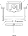
Figure 1 shows a front view of a seat assembly. -
Figure 1a shows a rear view of a seat assembly -
Figure 2 shows a side view of the seat assembly. -
Figure 3 shows a three-dimensional view of the seat assembly. -
Figure 3a shows an exploded side view of the seat assembly. -
Figure 4 shows a first close up frontal view of a rotational alignment mechanism during mounting. -
Figure 5 shows a second close up frontal view of the rotational alignment mechanism once mounted for use. -
Figure 6 shows an isometric view of an end of a pillar. -
Figure 7 shows a side view of the end of the pillar. -
Figure 8 shows a section view of the mounting assembly from the front. -
Figures 1-3 show aseating assembly 2. Theseating assembly 2 is configured to support a user of a vehicle in use (i.e. provide a seat). Theseating assembly 2 is intended for use with a vehicle adapted for people with mobility issues, such as a mobility scooter. - The
seating assembly 2 comprises aseat portion 4 configured to support the user's buttocks and legs in use. A back-rest 6 is provided at a rear side of the seat portion and is configured to supports the user's back in use, e.g. in a lumbar and/or thoracic region of the spine. Two arm-rests 8 are provided at the sides of the seat portion and are configured to supports the user's arms, e.g. forearms, in use. - The
seat portion 4 and/or back-rest 6 and/or arm-rests 8 may comprise cushioning material or the like configured to support and provide comfort for the user. Conventional foam or other padding may be used. - The
assembly 2 comprises amounting assembly 10 configured to connect theassembly 2 to the vehicle. - The
mounting assembly 10 comprises ayoke 12 configured to support theseat portion 4, the back-rest 6 and the arm-rests 8 in use, whilst allowing simple disassembly thereof by an end user. - The
yoke 12 comprises acentral portion 14 configured to engage and removably connect to theseat portion 4, e.g. on an underside of the seat. A plurality ofarms 16 extend outwardly from thecentral portion 14 to support the back-rest 6 and the arm-rests 8 respectively (e.g. in a T-shaped arrangement). Thecentral portion 14 thus comprises a junction for the arms, with the arms each having a proximal end at thecentral portion 14 and a distal end to which the back/arm rest 6/8 is attached. - The
arms 16 are substantially L-shaped. Thearms 16 comprise a substantially horizontal portion and an upwardly-extending (e.g. vertical) portion, with the back-rest/arm-rests connected to an end of the upwardly extending portions. - The
seat portion 4 comprises a plurality ofchannels 18 formed in an underside thereof to receive thearms 16, i.e. part way along the length of each arm depending from thecentral portion 14. Thearms 16 therefore lie flush with the underside of theseat portion 4 when assembled. Theseat portion 4 may comprise a moulded base, thereby allowing convenient adaption to the shape of thearms 16. - The upwardly-extending portions of the arms are located beyond the perimeter of the
seat portion 4. - The back-
rest 6 and arm-rests 8 are removably attached to the yoke 12 (i.e. via the arms 16). The back-rest 6 and arm-rests 8 are therefore separable from theseat portion 4. The back-rest 6 and arm-rests 8 comprise aprotrusion 20 configured to be received within the arms 16 (i.e. within a hollow section of the arms 16). - The back-
rest 6 and arm-rests 8 may be secured to thearms 16 by a securing means, for example, fasteners or latches etc. Alternatively, the back-rest 6 and arm-rests 8 may be connected to thearm 16 by a loose/interference connection (i.e. by friction between theprotrusions 20 and the arms 16). The protrusion in this example comprises a plurality of splines to provide a close frictional engagement in the hollow interior of thearms 16. - The mounting
assembly 10 comprises abase portion 22 configured to be connected to the vehicle in use. Thebase portion 22 is configured to be connected to the vehicle in a permanent or semi-permanent fashion (i.e. the connection is maintained in day-to-day use). Thebase portion 22 is typically a permanent installation of the vehicle. - The
base portion 22 comprises apillar 24 mounted so as to extend upwardly from the vehicle. Thepillar 24 comprises a plurality/series ofapertures 26 along a lower portion thereof to receive fasteners or the like. - An upper end of the
pillar 24 comprises a mountingplate 29 for mounting of both anupper pillar portion 28 and a liftingsupport structure 30 configured to allow lifting of the vehicle, e.g. using a hoist mechanism. The lifting structure comprises across bar 31 and brackets depending from thecross bar 31 at either side of the seat portion to allow attachment of webbing for lifting the vehicle. The specific details of the lifting structure and hoist mechanism are less relevant to the present invention and will not be described further. Theupper pillar portion 28 may be affixed atop thepillar 24 using other conventional means and provides a formation arranged to receive theyoke 12 of the seat assembly as will be described below. Theupper pillar portion 28 may be hollow or recessed in this regard, i.e. arranged to receive a protrusion of theyoke 12, or vice versa. - The
yoke 12 is removably coupled to thebase portion 22 when mounted. Theyoke 12,seat portion 4, back-rest 56 and arm-rests 8 are therefore separable from thepillar 24 of the vehicle. - The
yoke 12 comprises ashaft 32 on a lower side thereof. Theshaft 32 is configured to be received within an opening of theupper end portion 28 of thepillar 24. Theshaft 32 is loosely insertable in thepillar 24 to correctly align theyoke 12 with thepillar 24 for use. The yoke is thus loosely coupled on the pillar (i.e. held thereon primarily under action of the gravity) and is freely rotatable about anaxis 33. The loose connection allows theseat yoke 12 andseat portion 4 etc. to be simply lifted off the vehicle. - The length of the
shaft 32 is sufficient to prevent accidental toppling of the yoke off the pillar in normal use and its length may be, for example, at least two or three times the diameter of theshaft 32 and/or the diameter of the opening in the pillar. Both the pillar opening andshaft 32 are cylindrical in this example. Either or both of the opposing surfaces of theshaft 32 or pillar opening may be textured or profiled if desired to promote a particular frictional/interference engagement. However in the present example, the opposing surfaces are smooth to offer minimal resistance to rotation of the seat assembly when mounted on the pillar. - The interface between the
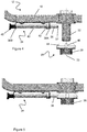
yoke 12 and thepillar 24, i.e. theupper pillar portion 28, is shown in further detail infigures 4-6 . - An
engagement mechanism 34 is provided on theyoke 12. The engagement mechanism may be mounted on an underside on one of thearms 16, e.g. one of the lateral arms supporting the arm-rests 8. - The engagement mechanism comprises a
pin 36 resiliently biased toward theaxis 33 and/orshaft 32. Therefore, as shown infigure 5 , thepin 36 is biased toward engagement with theupper pillar portion 28 when theyoke 12 and thepillar 24 are connected. - The
pin 36 extends along the horizontal portion of the arm 16 (i.e. in a direction transverse to the axis ofrotation 33 of the yoke 12). Thepin 36 is supported by a plurality of brackets 38 spaced along thearm 16. An end of thepin 36 comprises ahandle 40, e.g. in the form of a knob, to allow the user to grasp and move thepin 36 against the biasing force. Thehandle 40 is located proximal the side edge of the seat portion 4 (e.g. adjacent the radially outer end of the armrest), thereby providing easy access for the user. - The
pin 36 has arounded end 37 for engagement with the upper pillar portion 38. - The pin comprises a
stop member 42 configured to abut one of thebrackets 38A to limit movement thereof in a direction to/from theaxis 33. Aspring 43 is operatively located between thestop member 42 and the other of thebrackets 38B, thereby biasing the stop member into abutment with thebracket 38A. The user therefore pulls thepin 36 against the bias to disengage thepin 36 from thepillar 24. - The
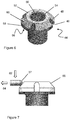
upper pillar portion 28 comprises ahead formation 44 configured to engage thepin 36. Thehead portion 44 may be provided at the upper end of thepillar 24, e.g. at the upper extremity ofupper pillar portion 28. The head formation may comprise a diameter/width dimension that is greater than the remainder of theupper pillar portion 28 and/orpillar 24. An outer/peripheral surface of thehead formation 44 is radially beyond theend 37 of the pin in its at-rest condition shown infigures 4 and 5 . - The
head portion 44 comprises a plurality ofrecesses 46 therein configured to receive thepin 36, i.e. theend 37 thereof. Engagement of thepin 36 and recesses 46 thereby prevent relative rotation of theyoke 12 and the pillar 24 (i.e. lock the angular position of theseat portion 4/yoke 12 about the axis 33). Therecesses 46 are shaped to conform with the shape of the pin 36 (e.g. the same diameter/cross-sectional shape and/or curved profile), such that thepin 36 is snugly received therein. The snug fit can help to prevent any wobbling of theyoke 12 when locked. - The
recesses 46 are angularly spaced about thepillar 24, thus providing a plurality of discrete, angularly spaced positions in which theyoke 12 may be rotationally locked/latched relative to theaxis 33. This allows the user to rotate theseat assembly 2 to face different directions in use. For example, as shown infigure 6 , a recess is provided for a forward facing position, a left facing position, a right facing position and rearward facing position. Therecesses 46 are thus spaced by 90°. However, it can be appreciated that any number ofrecesses 46 may provided and the angular spacing/positions may vary according the user's needs. A plurality of recesses may thus be angularly spaced as desired, although it is proposed that angular spacings of 45° or 90° may be preferred to accommodate at least forward-facing and lateral-facing positions. - The recesses act as latching abutments for the pin.
- The
recesses 46 extend in a direction substantially parallel to the axis of rotation 33 (herein referred to as the "axial direction"). The cross-section of therecesses 46 is substantially uniform and/or otherwise unobstructed along the axial direction. - In other words, the
recesses 46 have a diameter greater or equal to the diameter of thepin 36 along the axial direction. Therecesses 46 therefore permit relative movement of the pin in an axial direction, even when rotationally latched. - The
recesses 46 have an open/unobstructed end, and therefore thepin 36 may disengage therecesses 46 by sufficient axial movement thereof. This allows the user to lift off theyoke 12 whilst thepin 36 is engaged with therecesses 46. The shape of therecesses 46 therefore prevent relative rotation between pillar and the seat portion about therotational axis 33 but permit mounting and/or unmounting of the seat portion in the axial direction. - The head portion comprises an
aperture 50 therein configured to receive theyoke shaft 32. Arim 52 surrounds theaperture 50. Therim 52 comprises a substantially flat, annular upper surface arranged to bear thecentral portion 14 of the yoke thereon. An inwardly angled/chamferedsurface 54 is provided between theaperture 50 and therim 52 to help guide theshaft 32 into theaperture 50. - The
head potion 44 comprises a low friction material, for example, nylon. In particular, the rim and the inner surface of theaperture 50 comprise the low friction material. Thehead portion 44 is received within theend portion 28 of the pillar 24 (seefigure 8 ), e.g. as an insert member within a metallic supporting part of theend portion 28. - The
head portion 44 comprises aflange 56 extending radially beyond therim 52 and/or end portion 28 (i.e. in an annular fashion). Theflange 56 comprises an outer/side wall 58. Theflange 56 and/orhead portion 44 comprises an angled/chamferedupper surface 60. The chamferedupper surface 60 extends at an oblique angle between theside wall 58 and therim 52. Therecesses 46 extend through the flange 56 (e.g. in a direction substantially perpendicular thereto). Therecesses 46 thus define arched or horse-shoe shaped discontinuities in the chamferedupper surface 60. - The chamfered
surface 60 is configured to move thepin 36 in toward/away from thepillar 24 in a radial direction during movement of thepin 36 relative to thepillar 24 in an axial direction. For example, as shown infigure 7 , as thepin 36 is moved in a downwardaxial direction 62, the chamferedsurface 60 moves thepin 36 in anoutward direction 64. The chamferedsurface 60 therefore imparts a transverse movement of thepin 36 during axial movement of thepin 36 across thesurface 60. Therounded head 37 of the pin allows thepin 36 to slide across thesurface 60. - During downward axial movement, the chamfered
surface 60 acts against the spring bias to move thepin 36 toward a retracted position, until it engages theside wall 64. At this point, further axial movement of thepin 36 is prevented as thehead portion 44 engages the yoke (seefigure 5 ). The engagement mechanism is therefore automatically retracted upon mounting of theyoke 12 onto thepillar 24. This means a user does not need to angularly align thepin 36 with arecess 48 during mounting of the yoke/seat assembly on thepillar 24. - The
yoke 12 may then be rotated until thepin 36 is into alignment within one of therecesses 46, at which point thepin 36 will be biased into therecess 46 and the yoke is locked relative to thepillar 24. Such an arrangement therefore allows the user to place the seat onto thepillar 24 at any angle and then rotate the seat until it "snaps" into position. Additionally, this prevents any damage to thepin 36. - If the seat is placed onto the
pillar 24 with thepin 36 aligned with one of therecesses 46, thepin 36 will merely slide down therecess 46 until theyoke 12 engages thepillar 24. The seat will therefore already be in a locked position. - Once assembled, should the user wish to rotate the seat, the user can pull the
handle 40, thereby disengaging thepin 36 from therecess 46 and allowing rotation of theseat portion 4/yoke 12 relative to thepillar 24. - The connections between the
seat portion 4 and theyoke 12 is shown in further detail infigure 8 . - The
seat portion 4 comprises a protrusion/pin 66 at an underside thereof. Thepin 66 is configured to be received within anaperture 68 in the yoke 12 (i.e. thecentral portion 14 thereof). Theaperture 68 may extend, e.g. axially, within theyoke protrusion 32. - The
pin 66 comprises ashoulder formation 70 of greater width proximal the seat portion and extends to a distal/free end. The free end may be chamfered. - A bearing
member 72 is provided on the yoke, e.g. within theaperture 68, and is arranged to receive the pin. Thebearing 72 takes the form of a simple annular member in this example, which comprises a low-friction material, for example, nylon. The bearingmember 72 comprises an upper rim and an elongate/tubular section depending therefrom. The upper rim is shaped to abut theshoulder formation 70 when the pin is inserted into the bearing member. This has been found to provide an effective hard-wearing and low-friction bearing. - The bearing 72 in this example provides a neck formation at the entrance to the
aperture 68, e.g. in the form of a collar formation. The aperture and bearing are tubular in form and the pin is cylindrical. Rotation between theseat portion 4 andyoke 12 is prevented by the interaction between thearms 16 and profiled underside of theseat portion 4. In other examples, thepin 66 and aperture/bearing could be of corresponding, non-circular form to prevent rotation between theseat portion 4 and theyoke 12. For example, thepin 66 and aperture could be polygonal/elli ptical. - The
yoke aperture 68 comprises an inwardly angled/chamferedsurface 74 at an upper end thereof. The obliquely angledsurface 74 is enlarged compared to the other chamfered surfaces described herein and acts to guide thepin 66 into the aperture. This is beneficial because the seat portion obscures thepin 66 during mounting onto the yoke and so thesurface 74 assists the user in achieving the desired axial alignment between thepin 66 andaperture 68. The slight chamfer at the distal end of thepin 66 may also assist with the alignment. - The chamfered
surface 74 provides a narrowing of theaperture 68. Therefore thebearing 72 has a reduced diameter compared with the upper/open end of thesurface 74. Thesurface 74 andaperture 68 collectively define a funnel-like form that is closed at its lower end. - Similar to the connection between the
yoke 12 and thepillar 24, theseat portion 4 is loosely mounted on the yoke 12 (i.e. held thereon primarily under action of the gravity alone). Theseat portion 4 may therefore be separated from theyoke 12 by merely lifting it therefrom. - In this way, the
yoke 12 andseat portion 4 can simply be stacked in sequence upon thepillar 24 in order to assemble the seat upon the mobility scooter. - The present invention allows convenient and simple attachment and detachment of the seat from a mobility scooter. The arrangement does not require the user to reach under the seat to unlatch a securing mechanism or fastener etc. The seat assembly can be attached to the pillar in any orientation and then rotated into a rotationally-latched position. This increases the ease of use for people with reduced mobility.
- The seating assembly may be assembled or disassembled incrementally (i.e. attaching/removing the seat portion, back-rest, arm-rests, and yoke sequentially). This reduces the load the user is required to lift or hold.
- The loose connections allow the user to simply lift each component way from another. This method is simple and easy to perform for people with reduced mobility. Additionally, this can be performed using a single hand. Furthermore none of the individual components are awkward to hold, nor do they require any significant leaning or stretching by the user to assemble or disassemble.
- The chamfered apertures provide a self-locating arrangement. This mitigates the need to guide and/or observe the various components during assembly thereof.
Claims (15)
- A seat assembly for a mobility scooter comprising:a seat portion for supporting an operator of the mobility scooter in use;a yoke arranged to receive the seat portion and comprising a mounting formation for mounting of the yoke to a support member of the mobility scooter such that the yoke is removably mounted atop the support member and the seat portion is removably mounted atop the yoke in use, where the yoke comprises one or more attachment formation for releasable attachment of at least one of an arm-rest and a back-rest for the seat portion; andwhere the seat portion is liftable off the yoke as a first component and the yoke is liftable off the support member as a further component when removing the seat assembly from the mobility scooter.
- A seat assembly according to claim 1, where the mounting member is provided on an underside of the yoke, such that the yoke is intermediate the seat portion and the support member in use.
- A seat assembly according to claim 1 or 2, where the yoke is loosely mounted on the support member, such that lifting of the yoke can be effected by substantially lifting only against gravity.
- A seat assembly according to any preceding claim where one of the yoke mounting formation and support member comprise a protrusion configured to be received by an aperture in the other of the mounting formation and the support member.
- A seat assembly according to any preceding claim where one of the seat portion and the yoke comprise a protrusion configured to be received by an aperture in the other of the seat portion and the yoke.
- A seat assembly according to claim 5 when dependent on claim 4, wherein the yoke comprises both a protrusion for engaging an aperture of the support member and also an aperture for receiving a protrusion on the underside of the seat portion.
- A seat assembly according to claim 6, where the aperture of the yoke is axially aligned with the protrusion of the yoke.
- A seat assembly according to claim 6, where the aperture of the yoke opens into a hollow interior of the protrusion of the yoke.
- A seat assembly according to any one of claims 5 to 8, where one or more of the apertures or protrusions comprise a chamfered edge or opening configured to guide the protrusion into the aperture.
- A seat assembly according to claim 9, where the aperture is funnel-like in form, having a chamfered section and a cylindrical section.
- A seat assembly according to any one of claims 5 to 10, where one of the aperture and the protrusion comprise a bearing formation for supporting rotation of the other of the aperture and protrusion in a weight bearing relationship when mounted.
- A seat assembly according to any one of claims 5 to 10, where one or more of the apertures and/or protrusions comprises a low friction material, such as nylon.
- A seat assembly according to any one of the preceding claims, comprising two arm rests and the back rest, all of which are removably and/or releasably mounted to the yoke.
- A seat assembly for a mobility scooter comprising:a pillar configured to connect the scooter in use;a seat portion for supporting an operator of the vehicle in use, the seat portion removably mounted to the pillar and rotatable relative thereto about an axis when mounted;one of the pillar and the seat portion comprising an engagement member configured to releasably engage at least one alignment formation provided at an angular position on the other of the pillar and the seat portion; andwhere the alignment formation is shaped such that when the engagement formation is engaged therewith, relative rotation between pillar and the seat portion about the axis is prevented and mounting/unmounting of the seat portion in an axial direction is permitted.
- A seat assembly according to claim 14, where the alignment formation comprises an axially aligned abutment surface having a depth in a radial direction and/or one or more recess that is open in an axial direction.
Applications Claiming Priority (1)
| Application Number | Priority Date | Filing Date | Title |
|---|---|---|---|
| GB1916523.2A GB2588917B (en) | 2019-11-13 | 2019-11-13 | Seat assembly |
Publications (3)
| Publication Number | Publication Date |
|---|---|
| EP3822115A2 true EP3822115A2 (en) | 2021-05-19 |
| EP3822115A3 EP3822115A3 (en) | 2021-07-07 |
| EP3822115B1 EP3822115B1 (en) | 2024-02-28 |
Family
ID=69062335
Family Applications (1)
| Application Number | Title | Priority Date | Filing Date |
|---|---|---|---|
| EP20207643.6A Active EP3822115B1 (en) | 2019-11-13 | 2020-11-13 | Seat assembly |
Country Status (4)
| Country | Link |
|---|---|
| US (1) | US11285060B2 (en) |
| EP (1) | EP3822115B1 (en) |
| AU (1) | AU2020267319A1 (en) |
| GB (1) | GB2588917B (en) |
Citations (1)
| Publication number | Priority date | Publication date | Assignee | Title |
|---|---|---|---|---|
| US20040026949A1 (en) | 2002-08-09 | 2004-02-12 | Chun-Moun Lin | Electric mobility scooter storage room |
Family Cites Families (16)
| Publication number | Priority date | Publication date | Assignee | Title |
|---|---|---|---|---|
| US2376713A (en) * | 1943-02-13 | 1945-05-22 | William P Murrell | Bicycle seat |
| BE792744A (en) * | 1972-01-03 | 1973-03-30 | Mauser Kg | SEAT OR ROTATING ARMCHAIR MOUNTED ON A SPRING WITH ADJUSTABLE LEVEL |
| GB1572205A (en) | 1976-11-22 | 1980-07-23 | Southward Eng Co Ltd | Transportation of disabled or invalided persons |
| US5020624A (en) * | 1989-11-13 | 1991-06-04 | Everest & Jennings, Inc. | Power drive scooter |
| FR2699129B1 (en) | 1992-12-15 | 1995-02-10 | Rene Baboulin | Device for the transfer, in and out of a vehicle, of at least one part forming the seat of a wheelchair intended for a disabled person; wheelchair and vehicle partially incorporating this device. |
| US6164725A (en) * | 1999-03-09 | 2000-12-26 | Santa Cruz; Cathy D. | Detachable passenger arm rest for two wheeled vehicles |
| US6227510B1 (en) * | 1999-06-16 | 2001-05-08 | Mcmullen, Sr. Donald A. | Hand-size container holder |
| TW478712U (en) * | 2000-04-12 | 2002-03-01 | Sen-Sung Lin | Silver material control device for chip silver-soaking machine |
| US6854238B2 (en) * | 2002-11-12 | 2005-02-15 | Alfred Boots | Structural connection system for frameworks |
| US7226065B2 (en) * | 2005-04-21 | 2007-06-05 | Kelly Hutson | Bicycle seat |
| US7131696B1 (en) * | 2005-07-19 | 2006-11-07 | Giant Manufacturing Co., Ltd. | Seat device for a vehicle |
| US7278672B2 (en) * | 2005-10-27 | 2007-10-09 | Sunpex Technology Co., Ltd. | Motor vehicle with direction-lockable seat assembly |
| US7887138B2 (en) * | 2009-01-23 | 2011-02-15 | Chen Yung-Hua | Integrally formed base arrangement of an office chair |
| GB2542556A (en) * | 2015-09-16 | 2017-03-29 | Tomcat Special Needs Innovation Ltd | Seat docking apparatus |
| DE112016007072T5 (en) * | 2016-08-15 | 2019-04-25 | Ford Global Technologies, Llc | Personal mobility kit |
| US9999562B1 (en) * | 2017-03-30 | 2018-06-19 | Yun-Hsiu Yeh | Walker device |
-
2019
- 2019-11-13 GB GB1916523.2A patent/GB2588917B/en active Active
-
2020
- 2020-11-13 US US17/097,324 patent/US11285060B2/en active Active
- 2020-11-13 AU AU2020267319A patent/AU2020267319A1/en active Pending
- 2020-11-13 EP EP20207643.6A patent/EP3822115B1/en active Active
Patent Citations (1)
| Publication number | Priority date | Publication date | Assignee | Title |
|---|---|---|---|---|
| US20040026949A1 (en) | 2002-08-09 | 2004-02-12 | Chun-Moun Lin | Electric mobility scooter storage room |
Also Published As
| Publication number | Publication date |
|---|---|
| AU2020267319A1 (en) | 2021-05-27 |
| EP3822115B1 (en) | 2024-02-28 |
| US20210137758A1 (en) | 2021-05-13 |
| GB2588917B (en) | 2023-08-30 |
| EP3822115A3 (en) | 2021-07-07 |
| US11285060B2 (en) | 2022-03-29 |
| GB201916523D0 (en) | 2019-12-25 |
| GB2588917A (en) | 2021-05-19 |
Similar Documents
| Publication | Publication Date | Title |
|---|---|---|
| EP1049392B1 (en) | Feeding seat | |
| US20040155500A1 (en) | Booster seat | |
| EP0136796A2 (en) | Adjustable chair | |
| US6752464B1 (en) | Modular furniture frame | |
| WO1995035053A1 (en) | Improved wheelchair back system | |
| WO2014150734A1 (en) | Exercise device, connector and methods of use thereof | |
| WO1999040819A1 (en) | Child support device with displaceable seat element | |
| EP2228253B1 (en) | Child vehicle seat as well as a base suitable for such a child vehicle seat | |
| US6948777B2 (en) | Chair with storable ottoman | |
| CN202283142U (en) | High dining chair | |
| CN219742239U (en) | Modularized ergonomic chair capable of being assembled without fastening piece | |
| US20110272986A1 (en) | Chair construction and method therefore | |
| EP3053485A1 (en) | Adjustable booster seat | |
| EP3998910B1 (en) | Booster seat for children | |
| US11751690B2 (en) | Seating furniture chassis | |
| KR200485004Y1 (en) | assembly type sofa using head restraint | |
| EP3822115A2 (en) | Seat assembly | |
| EP1613192B1 (en) | Seating assembly for wheelchairs and strollers | |
| WO2020061493A1 (en) | Detachable bed rail | |
| CN114727704A (en) | Baby chair | |
| US20210330087A1 (en) | Seating furniture chassis | |
| US7314201B2 (en) | Dampened retractable furniture cup holder | |
| US5335971A (en) | Foldable chair | |
| EP3409256A1 (en) | Locking mechanism of an armrest assembly for a wheelchair and a wheelchair comprising the same | |
| KR101653705B1 (en) | Clutching device for a vehicle armrest assembly |
Legal Events
| Date | Code | Title | Description |
|---|---|---|---|
| PUAI | Public reference made under article 153(3) epc to a published international application that has entered the european phase |
Free format text: ORIGINAL CODE: 0009012 |
|
| STAA | Information on the status of an ep patent application or granted ep patent |
Free format text: STATUS: THE APPLICATION HAS BEEN PUBLISHED |
|
| AK | Designated contracting states |
Kind code of ref document: A2 Designated state(s): AL AT BE BG CH CY CZ DE DK EE ES FI FR GB GR HR HU IE IS IT LI LT LU LV MC MK MT NL NO PL PT RO RS SE SI SK SM TR |
|
| PUAL | Search report despatched |
Free format text: ORIGINAL CODE: 0009013 |
|
| AK | Designated contracting states |
Kind code of ref document: A3 Designated state(s): AL AT BE BG CH CY CZ DE DK EE ES FI FR GB GR HR HU IE IS IT LI LT LU LV MC MK MT NL NO PL PT RO RS SE SI SK SM TR |
|
| RIC1 | Information provided on ipc code assigned before grant |
Ipc: B60N 2/14 20060101AFI20210531BHEP Ipc: B60N 2/16 20060101ALI20210531BHEP Ipc: B60N 2/70 20060101ALI20210531BHEP Ipc: B60N 2/75 20180101ALI20210531BHEP Ipc: A61G 5/12 20060101ALI20210531BHEP Ipc: A61G 5/10 20060101ALI20210531BHEP |
|
| STAA | Information on the status of an ep patent application or granted ep patent |
Free format text: STATUS: REQUEST FOR EXAMINATION WAS MADE |
|
| 17P | Request for examination filed |
Effective date: 20220107 |
|
| RBV | Designated contracting states (corrected) |
Designated state(s): AL AT BE BG CH CY CZ DE DK EE ES FI FR GB GR HR HU IE IS IT LI LT LU LV MC MK MT NL NO PL PT RO RS SE SI SK SM TR |
|
| STAA | Information on the status of an ep patent application or granted ep patent |
Free format text: STATUS: EXAMINATION IS IN PROGRESS |
|
| 17Q | First examination report despatched |
Effective date: 20230130 |
|
| GRAP | Despatch of communication of intention to grant a patent |
Free format text: ORIGINAL CODE: EPIDOSNIGR1 |
|
| STAA | Information on the status of an ep patent application or granted ep patent |
Free format text: STATUS: GRANT OF PATENT IS INTENDED |
|
| INTG | Intention to grant announced |
Effective date: 20231106 |
|
| GRAS | Grant fee paid |
Free format text: ORIGINAL CODE: EPIDOSNIGR3 |
|
| GRAA | (expected) grant |
Free format text: ORIGINAL CODE: 0009210 |
|
| STAA | Information on the status of an ep patent application or granted ep patent |
Free format text: STATUS: THE PATENT HAS BEEN GRANTED |
|
| AK | Designated contracting states |
Kind code of ref document: B1 Designated state(s): AL AT BE BG CH CY CZ DE DK EE ES FI FR GB GR HR HU IE IS IT LI LT LU LV MC MK MT NL NO PL PT RO RS SE SI SK SM TR |
|
| REG | Reference to a national code |
Ref country code: GB Ref legal event code: FG4D |
|
| REG | Reference to a national code |
Ref country code: CH Ref legal event code: EP |
|
| REG | Reference to a national code |
Ref country code: DE Ref legal event code: R096 Ref document number: 602020026341 Country of ref document: DE |
|
| REG | Reference to a national code |
Ref country code: IE Ref legal event code: FG4D |