EP3821847B1 - Dental implant with improved prosthetic interface - Google Patents
Dental implant with improved prosthetic interface Download PDFInfo
- Publication number
- EP3821847B1 EP3821847B1 EP20177859.4A EP20177859A EP3821847B1 EP 3821847 B1 EP3821847 B1 EP 3821847B1 EP 20177859 A EP20177859 A EP 20177859A EP 3821847 B1 EP3821847 B1 EP 3821847B1
- Authority
- EP
- European Patent Office
- Prior art keywords
- abutment
- implant
- facing surface
- dental
- apical end
- Prior art date
- Legal status (The legal status is an assumption and is not a legal conclusion. Google has not performed a legal analysis and makes no representation as to the accuracy of the status listed.)
- Active
Links
- 239000004053 dental implant Substances 0.000 title claims description 47
- 239000007943 implant Substances 0.000 claims description 173
- 230000013011 mating Effects 0.000 claims description 20
- 238000007789 sealing Methods 0.000 description 20
- 210000000988 bone and bone Anatomy 0.000 description 15
- 230000033001 locomotion Effects 0.000 description 12
- 210000001519 tissue Anatomy 0.000 description 12
- 230000008901 benefit Effects 0.000 description 8
- 241000894006 Bacteria Species 0.000 description 5
- 239000000463 material Substances 0.000 description 5
- 230000036316 preload Effects 0.000 description 4
- RTAQQCXQSZGOHL-UHFFFAOYSA-N Titanium Chemical compound [Ti] RTAQQCXQSZGOHL-UHFFFAOYSA-N 0.000 description 3
- 239000000560 biocompatible material Substances 0.000 description 3
- 238000005336 cracking Methods 0.000 description 3
- 208000002925 dental caries Diseases 0.000 description 3
- 238000012423 maintenance Methods 0.000 description 3
- 238000000034 method Methods 0.000 description 3
- 238000010883 osseointegration Methods 0.000 description 3
- 239000010936 titanium Substances 0.000 description 3
- 229910052719 titanium Inorganic materials 0.000 description 3
- 230000007704 transition Effects 0.000 description 3
- MCMNRKCIXSYSNV-UHFFFAOYSA-N Zirconium dioxide Chemical compound O=[Zr]=O MCMNRKCIXSYSNV-UHFFFAOYSA-N 0.000 description 2
- 239000012620 biological material Substances 0.000 description 2
- 239000011248 coating agent Substances 0.000 description 2
- 238000000576 coating method Methods 0.000 description 2
- 230000000295 complement effect Effects 0.000 description 2
- 230000003993 interaction Effects 0.000 description 2
- 230000001788 irregular Effects 0.000 description 2
- 239000011859 microparticle Substances 0.000 description 2
- 238000005086 pumping Methods 0.000 description 2
- 210000004872 soft tissue Anatomy 0.000 description 2
- 238000001356 surgical procedure Methods 0.000 description 2
- 229910000684 Cobalt-chrome Inorganic materials 0.000 description 1
- 241000124008 Mammalia Species 0.000 description 1
- 208000031737 Tissue Adhesions Diseases 0.000 description 1
- NRTOMJZYCJJWKI-UHFFFAOYSA-N Titanium nitride Chemical compound [Ti]#N NRTOMJZYCJJWKI-UHFFFAOYSA-N 0.000 description 1
- 238000005452 bending Methods 0.000 description 1
- 239000000316 bone substitute Substances 0.000 description 1
- 210000004027 cell Anatomy 0.000 description 1
- 239000000919 ceramic Substances 0.000 description 1
- 230000008859 change Effects 0.000 description 1
- 239000010952 cobalt-chrome Substances 0.000 description 1
- 230000001054 cortical effect Effects 0.000 description 1
- 230000007423 decrease Effects 0.000 description 1
- 230000001419 dependent effect Effects 0.000 description 1
- 230000001627 detrimental effect Effects 0.000 description 1
- 238000005553 drilling Methods 0.000 description 1
- 230000009977 dual effect Effects 0.000 description 1
- 230000000694 effects Effects 0.000 description 1
- 239000012530 fluid Substances 0.000 description 1
- -1 for example Substances 0.000 description 1
- 230000036541 health Effects 0.000 description 1
- 229910052588 hydroxylapatite Inorganic materials 0.000 description 1
- 208000015181 infectious disease Diseases 0.000 description 1
- 208000014674 injury Diseases 0.000 description 1
- 229910052751 metal Inorganic materials 0.000 description 1
- 239000002184 metal Substances 0.000 description 1
- 230000003278 mimic effect Effects 0.000 description 1
- 230000000921 morphogenic effect Effects 0.000 description 1
- 230000000399 orthopedic effect Effects 0.000 description 1
- 230000002138 osteoinductive effect Effects 0.000 description 1
- 244000052769 pathogen Species 0.000 description 1
- 230000035515 penetration Effects 0.000 description 1
- XYJRXVWERLGGKC-UHFFFAOYSA-D pentacalcium;hydroxide;triphosphate Chemical compound [OH-].[Ca+2].[Ca+2].[Ca+2].[Ca+2].[Ca+2].[O-]P([O-])([O-])=O.[O-]P([O-])([O-])=O.[O-]P([O-])([O-])=O XYJRXVWERLGGKC-UHFFFAOYSA-D 0.000 description 1
- 210000004623 platelet-rich plasma Anatomy 0.000 description 1
- 229920000642 polymer Polymers 0.000 description 1
- 239000006041 probiotic Substances 0.000 description 1
- 230000000529 probiotic effect Effects 0.000 description 1
- 235000018291 probiotics Nutrition 0.000 description 1
- 102000004169 proteins and genes Human genes 0.000 description 1
- 108090000623 proteins and genes Proteins 0.000 description 1
- 230000000717 retained effect Effects 0.000 description 1
- 230000007480 spreading Effects 0.000 description 1
- 239000000126 substance Substances 0.000 description 1
- 229910052715 tantalum Inorganic materials 0.000 description 1
- GUVRBAGPIYLISA-UHFFFAOYSA-N tantalum atom Chemical compound [Ta] GUVRBAGPIYLISA-UHFFFAOYSA-N 0.000 description 1
- 230000008733 trauma Effects 0.000 description 1
Images


Classifications
-
- A—HUMAN NECESSITIES
- A61—MEDICAL OR VETERINARY SCIENCE; HYGIENE
- A61C—DENTISTRY; APPARATUS OR METHODS FOR ORAL OR DENTAL HYGIENE
- A61C8/00—Means to be fixed to the jaw-bone for consolidating natural teeth or for fixing dental prostheses thereon; Dental implants; Implanting tools
- A61C8/0048—Connecting the upper structure to the implant, e.g. bridging bars
- A61C8/0075—Implant heads specially designed for receiving an upper structure
-
- A—HUMAN NECESSITIES
- A61—MEDICAL OR VETERINARY SCIENCE; HYGIENE
- A61C—DENTISTRY; APPARATUS OR METHODS FOR ORAL OR DENTAL HYGIENE
- A61C8/00—Means to be fixed to the jaw-bone for consolidating natural teeth or for fixing dental prostheses thereon; Dental implants; Implanting tools
- A61C8/0048—Connecting the upper structure to the implant, e.g. bridging bars
- A61C8/005—Connecting devices for joining an upper structure with an implant member, e.g. spacers
- A61C8/006—Connecting devices for joining an upper structure with an implant member, e.g. spacers with polygonal positional means, e.g. hexagonal or octagonal
-
- A—HUMAN NECESSITIES
- A61—MEDICAL OR VETERINARY SCIENCE; HYGIENE
- A61C—DENTISTRY; APPARATUS OR METHODS FOR ORAL OR DENTAL HYGIENE
- A61C8/00—Means to be fixed to the jaw-bone for consolidating natural teeth or for fixing dental prostheses thereon; Dental implants; Implanting tools
- A61C8/0012—Means to be fixed to the jaw-bone for consolidating natural teeth or for fixing dental prostheses thereon; Dental implants; Implanting tools characterised by the material or composition, e.g. ceramics, surface layer, metal alloy
- A61C8/0013—Means to be fixed to the jaw-bone for consolidating natural teeth or for fixing dental prostheses thereon; Dental implants; Implanting tools characterised by the material or composition, e.g. ceramics, surface layer, metal alloy with a surface layer, coating
-
- A—HUMAN NECESSITIES
- A61—MEDICAL OR VETERINARY SCIENCE; HYGIENE
- A61C—DENTISTRY; APPARATUS OR METHODS FOR ORAL OR DENTAL HYGIENE
- A61C8/00—Means to be fixed to the jaw-bone for consolidating natural teeth or for fixing dental prostheses thereon; Dental implants; Implanting tools
- A61C8/0018—Means to be fixed to the jaw-bone for consolidating natural teeth or for fixing dental prostheses thereon; Dental implants; Implanting tools characterised by the shape
- A61C8/0022—Self-screwing
- A61C8/0025—Self-screwing with multiple threads
-
- A—HUMAN NECESSITIES
- A61—MEDICAL OR VETERINARY SCIENCE; HYGIENE
- A61C—DENTISTRY; APPARATUS OR METHODS FOR ORAL OR DENTAL HYGIENE
- A61C8/00—Means to be fixed to the jaw-bone for consolidating natural teeth or for fixing dental prostheses thereon; Dental implants; Implanting tools
- A61C8/0048—Connecting the upper structure to the implant, e.g. bridging bars
- A61C8/005—Connecting devices for joining an upper structure with an implant member, e.g. spacers
- A61C8/0054—Connecting devices for joining an upper structure with an implant member, e.g. spacers having a cylindrical implant connecting part
-
- A—HUMAN NECESSITIES
- A61—MEDICAL OR VETERINARY SCIENCE; HYGIENE
- A61C—DENTISTRY; APPARATUS OR METHODS FOR ORAL OR DENTAL HYGIENE
- A61C8/00—Means to be fixed to the jaw-bone for consolidating natural teeth or for fixing dental prostheses thereon; Dental implants; Implanting tools
- A61C8/0048—Connecting the upper structure to the implant, e.g. bridging bars
- A61C8/005—Connecting devices for joining an upper structure with an implant member, e.g. spacers
- A61C8/0066—Connecting devices for joining an upper structure with an implant member, e.g. spacers with positioning means
-
- A—HUMAN NECESSITIES
- A61—MEDICAL OR VETERINARY SCIENCE; HYGIENE
- A61C—DENTISTRY; APPARATUS OR METHODS FOR ORAL OR DENTAL HYGIENE
- A61C8/00—Means to be fixed to the jaw-bone for consolidating natural teeth or for fixing dental prostheses thereon; Dental implants; Implanting tools
- A61C8/0048—Connecting the upper structure to the implant, e.g. bridging bars
- A61C8/005—Connecting devices for joining an upper structure with an implant member, e.g. spacers
- A61C8/0068—Connecting devices for joining an upper structure with an implant member, e.g. spacers with an additional screw
-
- A—HUMAN NECESSITIES
- A61—MEDICAL OR VETERINARY SCIENCE; HYGIENE
- A61C—DENTISTRY; APPARATUS OR METHODS FOR ORAL OR DENTAL HYGIENE
- A61C8/00—Means to be fixed to the jaw-bone for consolidating natural teeth or for fixing dental prostheses thereon; Dental implants; Implanting tools
- A61C8/0048—Connecting the upper structure to the implant, e.g. bridging bars
- A61C8/005—Connecting devices for joining an upper structure with an implant member, e.g. spacers
- A61C8/0069—Connecting devices for joining an upper structure with an implant member, e.g. spacers tapered or conical connection
- A61C8/0071—Connecting devices for joining an upper structure with an implant member, e.g. spacers tapered or conical connection with a self-locking taper, e.g. morse taper
-
- A—HUMAN NECESSITIES
- A61—MEDICAL OR VETERINARY SCIENCE; HYGIENE
- A61C—DENTISTRY; APPARATUS OR METHODS FOR ORAL OR DENTAL HYGIENE
- A61C8/00—Means to be fixed to the jaw-bone for consolidating natural teeth or for fixing dental prostheses thereon; Dental implants; Implanting tools
- A61C8/0048—Connecting the upper structure to the implant, e.g. bridging bars
- A61C8/005—Connecting devices for joining an upper structure with an implant member, e.g. spacers
- A61C8/0074—Connecting devices for joining an upper structure with an implant member, e.g. spacers with external threads
Definitions
- the present patent document pertains generally to the field of dental implants and abutments.
- the invention disclosed herein can also be applied to other orthopedic applications such as spinal pedicel screws, bone screws used in trauma applications or other bone screws consisting of a three piece assembly (bone screw, adapting head, fastening screw). More particularly, but not by way of limitation, the patent document pertains to an interface between a dental implant and a dental abutment.
- a dental implant can be used in an oral treatment procedure to restore appearance or function of a removed tooth.
- a dental implant can mimic a root of a natural tooth that is replaced.
- a surgeon can replace the natural tooth with a prosthetic tooth that is mounted on a coronal portion of an abutment, which in turn, is attached to the dental implant on an apical portion.
- the surgeon can insert the dental implant into a dental bone cavity.
- a successful dental implant procedure generally requires more than bone affixation or osseointegration.
- Implant success can also require maintenance of the cortical bone at the coronal crest of the implant and maintenance of soft tissue structures in the implant region. The health of tissues in this region contributes to the aesthetic appearance of a full restoration. Maintenance of healthy tissue in the implant region can also lead to the creation of a tissue seal that hinders the propagation of infection along the implant body.
- US 2007/037123 and US 2012/295223 refer to dental abutments and implants.
- ectodermal tissue serves to protect against intrusion of bacteria and other foreign materials.
- An ectodermal tissue seal that protects the alveolar bone is known as the biologic width.
- the biologic width is a tissue ring and its position is dependent on the geometry and surgical placement of the dental implant.
- a micro-gap generally exists between the implant and the abutment. There is evidence to suggest that the position of the micro-gap has an effect on the position of the biologic width, and therefore on the height of the crestal alveolar bone.
- a conical connection might use interfacing shallow angle tapers on the abutment and the implant to shift the micro-gap. This connection can create a sealed interface that discourages penetration of bacteria or other foreign substances into a screw thread and other internal features of an implant body.
- the conical connection when used alone, can create a spreading force that tends to crack and split the implant.
- the present patent document describes examples that can include any one or combinations of an implant, an abutment, and an implant system.
- One or more of the described examples can offer the benefit of an offset micro-gap that can maintain the mechanical strength of a device.
- the examples can include one or more of several features, including but not limited to: 1) a sealing feature, 2) an more of several features, including but not limited to: 1) a sealing feature, 2) an interference fit feature, and 3) a stability feature.
- Some of the features can work together and overlap in design and structure, and all of the features can optionally be present in each example.
- each of the features can serve one or more functions.
- an interference fit feature can also provide a sealing function.
- the present patent document contemplates using one or more of three design components including: 1) a shoulder and matching engagement surface (shoulder connection); 2) a mating conical taper (conical connection); and 3) a mating anti-rotational means (anti-rotational means connection).
- An implant system can include an abutment that matches an implant.
- the implant can be configured with a surface that the shoulder engages and a mating conical taper.
- the implant can be configured with a conical taper and an anti-rotational means.
- One example can include all three components in both the implant and the abutment. The components can be combined in ways that can involve changing their function.
- the shoulder might provide a large percentage of the stability and a small percentage of the sealing. In another example the shoulder can provide a large percentage of the sealing.
- the conical tapers can have an interference fit
- the anti-rotational means can have an interference fit
- both the conical tapers and the anti-rotational means can have an interference fit.
- An interference fit between the abutment and the implant can provide sealing either between mating conical tapers or between mating anti-rotational means portions.
- Mating conical tapers can be referenced as a conical connection.
- a mating anti-rotational means connection can be referenced as an anti-rotational means connection.
- a connection between a shoulder on an abutment and a shoulder engaging surface on an implant can be referenced as a shoulder connection.
- An interference fit can be provided in either a conical connection or an anti-rotational means connection between the implant and abutment.
- An interference fit can be provided in both a conical connection and an anti-rotational means connection between the implant and abutment.
- both the conical connection and the anti-rotational means connection can have an interference fit.
- both the anti-rotational means connection and conical connection can have an interference fit; additional stability can be provided as well as an additional positioning limit because the two components are both entering into an interference fit simultaneously.
- One existing problem is that without some limit to prevent an abutment from moving too far apically as it is being tightened; there can be the possibility of cracking the implant if there is any taper feature, such as a conical connection.
- This problem can be overcome in at least two ways: 1) by having an abutment shoulder engaging the implant or 2) by having more than one component with an interference fit that limits apical movement of the abutment as it is tightened.
- Vertical forces such as bite forces
- a connection may have connecting surfaces on the abutment and the implant that are substantially perpendicular to the longitudinal axes of the implant and abutment. Bending loads may also be transferred at least in part by bearing along part of the connection.
- a dental implant is typically a cylinder with the longest dimension oriented parallel to the vertical component of a biting force. Through a connection with a shoulder, compressive loads are transmitted vertically in a direction of the greatest material thickness of the implant.
- An exemplary connection can be a combination of a shoulder connection and an interference fit between some portion of the implant and the abutment.
- the shoulder connection can offer mechanical strength and a definitive stop, while an interference fit between the abutment and the implant can limit rotation and create a seal with the above mentioned micro-gap offsetting advantages.
- the interface between an abutment and an implant can include a first element at the apical end of the abutment such as a hexagonal polygon.
- This polygon can create an anti-rotational interface with a similarly shaped socket in an implant.
- the polygon can be a friction fit like Zimmer Dental's TSV Hex-Lock ® connection.
- the polygon interface can also provide a way to index prosthetics. An orientation selected to build the prosthetic in a dental laboratory can be relocated when the prosthetic is placed in the patient.
- a second element of the combined connection between the implant and abutment can be located adjacent and coronal to the polygon, such as a conical taper.
- This element can feature a gradual taper that decreases in diameter in the apical direction.
- the angle of the taper can be in a range between about 1° and about 18°. This selection can assure that a tapered element of the abutment extends deep into a mating receptacle on the implant.
- the implant receptacle can also be conical and very close in angulations to the abutment cone. In this manner the two cones can have a longer area of engagement or interference where sealing can occur.
- Benefits of a long engagement of the tapered seal can include, for example: 1) stability between the implant and abutment; and 2) a seal that can prevent the exchange of fluids that may contain bacteria and other pathogens between the inside chamber of the implant and the outside environment.
- a phenomenon known as micro-pumping can transfer bacteria that have incubated inside of the implant onto soft and hard tissue adjacent to the implant. Micro-pumping can have a detrimental effect on tissue in an implant region and on the success of the implant restoration.
- a shoulder connection can have a shoulder that is oriented substantially perpendicular to the long access of the implant body and can create a substantially flat connection between the implant and the abutment. This flat connection can utilize the increased material thickness of the long axis to resist tipping forces.
- Another stable connection can be configured by having both a conical connection and an anti-rotational connection that are both tapered and have interference fits. This type of connection can be much more stable than a connection with only a conical connection. In a connection with only a conical connection, under sufficient loading, mating cones can act like a ball and socket joint and can be ineffective in preventing tipping (rotation perpendicular to the long axis) of an abutment.
- a flat shoulder connection between the implant and the abutment can also create a definite stop that can limit a cone to cone interference connection and therefore limit an outward force and hoop stress created by the cone to cone interference connection.
- the hex can be seated to virtually eliminate rotational micro-movement without becoming over stressed.
- a retaining fastener can connect an implant and an abutment.
- a high degree of retaining fastener pre-load can be assured by the combination connection of a conical connection and a shoulder connection.
- the shoulder connection seats, for example if a shoulder on the abutment contacts a mating surface of the implant, the vertical motion of the abutment can be prevented.
- a full torque applied to the fastener can act to stretch the fastener shaft. This stretching of the fastener shaft can store energy, which can maintain a clamping force that prevents the fastener from loosening.
- the taper in either or both of the conical connection or the anti-rotational means connection can be designed so that as the interference fit acquires the proper pre-load, the shoulder connection simultaneously forms a tight seal.
- a precise and known abutment seating height can be important clinically.
- the tooth prosthetic is made in a dental laboratory on an implant analog in a dental model and then transferred to a patient. Differences in a vertical seating height between the abutment in the analog and the abutment in the implant can result in aesthetic or even functional problems with the restoration.
- connection can be numerous but creating such a connection may require precise selection of the dimensions and tolerances of one or more of the three components (i.e., the conical connection, the anti-rotational means connection and the shoulder connection).
- the implant recess and abutment mating features are reversed or where the anti-rotational interface is of another geometry or excluded entirely are possible and are contemplated by this specification.
- a dental abutment for use with a dental implant comprising an abutment body having a longitudinal axis, a coronal end, and an apical end, wherein the abutment body includes a first externally facing surface, extending from a location between the coronal end and the apical end and towards the apical end, at least a portion of which tapers conically inwardly towards the apical end; an internal bore provided within the abutment body, at least a portion of the internal bore having internal threads; an external shoulder positioned between a coronal end of the first externally facing surface and the coronal end of the abutment body and a step portion located between the abutment coronal end and the abutment internal threads wherein the conically tapered portion of the first externally facing surface of the abutment forms an interference fit when in use with a mating conically tapered recess in the dental implant.
- the dental abutment can optionally be configured such that the first externally facing surface includes an anti-rotation feature.
- the dental abutment can optionally be configured such that the anti-rotation feature includes a polygon-shaped external perimeter.
- the dental abutment can optionally be configured to further comprise an anti-rotation feature positioned between an apical end of the first externally facing surface and the apical end of the abutment body.
- the dental abutment can optionally be configured such that the anti-rotation feature includes a polygon-shaped external perimeter.
- the dental abutment can optionally be configured such that the anti-rotation feature defines a second externally facing surface of the abutment body, at least a portion of the second externally facing surface tapered inwardly towards the apical end of the abutment body.
- the invention provides a dental implant system comprising an abutment as defined in claims 1 to 6 and an implant comprising: an implant body having a longitudinal axis, a coronal end, and an apical end; an implant internal bore, provided within the implant body, having a coronal end adjacent to the coronal end of the implant body and an apical end; a first internally facing surface extending from the coronal end of the implant internal bore towards the apical end of the implant internal bore, at least a portion of the first internally facing surface being conically tapered inwardly towards the apical end of the implant internal bore; and an internally threaded portion positioned within the implant internal bore between an apical end of the first internally facing surface and the apical end of the implant internal bore.
- the dental implant system can further comprise a fastener insertable within the internal bore of the abutment and configured to engage the internally threaded portion of the abutment and the internally threaded portion of the implant.
- the dental implant system can optionally be configured such that the first internally facing surface of the implant is configured to form an interference fit with the first externally facing surface of the abutment.
- the dental implant system can optionally be configured such that the first internally facing surface of the implant includes an implant anti-rotation feature configured to mate with an abutment anti-rotation feature included in the first externally facing surface of the abutment, and wherein the implant anti-rotation feature includes a polygon-shaped internal perimeter and the abutment anti-rotation feature includes a polygon-shaped external perimeter.
- the dental implant system can optionally be configured to further comprise an implant anti-rotation feature disposed within the implant internal bore between the apical end of the first internally facing surface and a coronal end of the implant internally threaded portion; and an abutment anti-rotation feature disposed between an apical end of the first externally facing surface of the abutment body and the apical end of the abutment body, wherein the implant anti-rotation feature is configured to mate with the abutment anti-rotation feature to inhibit rotation of the implant relative to the abutment.
- the dental implant system can optionally be configured such that the implant anti-rotation feature includes a polygon-shaped internal perimeter and the abutment anti-rotation feature includes a polygon-shaped external perimeter.
- the dental implant system can optionally be configured such that the implant anti-rotation feature defines a second internally facing surface of the implant internal bore, at least a portion of the second internally facing surface of the implant internal bore being tapered inwardly towards the apical end of the implant internal bore, and wherein the abutment anti-rotation feature defines a second externally facing surface of the abutment body, at least a portion of the second externally facing surface of the abutment body being tapered inwardly towards the apical end of the abutment body.
- a tapered connection between the implant and abutment can accomplish moving the sealing connection in this manner.
- Proper engineering of the length of the tapers and angle of the tapers can produce the tightest fit at a desired location in a tapered connection.
- the combination of a correctly placed shoulder connection and a tapered connection to an implant/abutment connection can provide stability and strength to the connection as well as an additional sealing surface.
- the shoulder connection is accomplished by using an external shoulder on the abutment to engage a mating surface on the implant.
- the interaction between the implant and abutment tapers for the conical connection and the placement of the shoulder can be precise to provide the proper preload on both the conical connection seal and the shoulder seal.
- the shoulder provides an exact vertical limit to the apical movement of the abutment as it is tightened down into the implant by a connecting fastener. This limit provides two advantages: it prevents the abutment cone from over stressing the implant conical features and it provides a repeatable vertical placement of the abutment.
- An additional advantage is that a fastener can be torqued to the point of stretching the fastener. The vertical height of the abutment will remain fixed because of the shoulder limit and the stretched fastener will provide added stability to the connection.
- the shoulder connection is used in conjunction with a conical connection or in conjunction with both a conical connection and an anti-rotational means connection. connections together.
- Another example which can provide added stability is a connection having both an interference fit conical connection and an interference fit anti-rotational connection.
- FIGS. 1 , 2A , and 3 -9 describe examples containing all three of the components mentioned above, the shoulder connection, the conical connection elements and the anti-rotational means connection features.
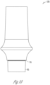
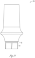
- FIGS. 2B , 2C , and 10 -12 describe examples containing only two of the three components and it should be understood that the more detailed description of the elements of FIGS. 1 , 2A , and 3 -9 can also apply to the examples described in FIGS. 2B , 2C , and 10 -12.
- FIG. 1 illustrates an example of a dental prosthetic apparatus 1 including a dental implant 5, an abutment 3, and a connecting fastener 2.
- the dental prosthetic apparatus 1 can provide an anchor for a prosthetic tooth (e.g., a crown) in an oral site where teeth are damaged or missing.
- the abutment 3 can include a base 4 configured to mate with the dental implant 5.
- the base 4 can be compared to features at the apical end of the abutment 3 and can vary (see FIGS. 5 , 10 , 11 , 12 ).
- the base 4 can be frictionally retained by a similarly-shaped recess 6 formed in the dental implant 5.
- the base 4 can have a polygonal exterior surface including a plurality of flat surfaces.
- the base 4 can be an anti-rotational component.
- the recess 6 in the dental implant 5 can include a polygonal shaped internal perimeter 7 (see FIG. 3 ) including a plurality of generally flat surfaces configured to mate with the base 4 of the abutment 3.
- the fastener 2 can include a longitudinal axis 8 extending between a fastener coronal end 9 and a fastener apical end 10.
- the fastener can have fastener threads 11 extending towards the fastener apical end 10.
- the fastener can include a shank portion 12 that is unthreaded between a fastener head 13 and the fastener apical end 10.
- the fastener head 13 can have a drive means 14 which could include a slotted form, a hex form, a torx form, a Phillips head form or any other driving means form.
- the fastener 2 can include a fastener shoulder surface 15 which is substantially transverse to the longitudinal axis 8 of the fastener 2.
- the fastener shoulder surface 15 can be a beveled surface.
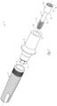
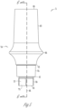
- FIG. 2A illustrates a dental implant 5 in cross section.
- the dental implant 5 can be fitted into a dental cavity formed in a patient's dental bone.
- the dental implant 5 can include a collar portion 16.
- the collar portion 16 can be the portion of the dental implant 5 forming the recess 6 in which the base 4 (See FIG. 1 ) of the abutment is inserted.
- the exterior surface of the collar portion 16 can be threaded, partially threaded, ridged, non-threaded, or saw toothed, the latter of which is pictured in FIG. 2A .
- the collar portion 16 may not be present in all examples.
- the dental implant 5 can include a longitudinally extending implant body 17, having a coronal end 18 and an apical end 19, adapted to be implanted into a dental cavity formed in the dental bone of a patient.
- the dental cavity can be formed according to known surgical techniques, for example, by a surgeon drilling into a patient's jaw bone at an edentulous site.
- the implant body 17 can include an externally facing surface 23 for interacting with bone tissue, thereby securing the dental implant 5 to the dental bone through osseointegration or other biological or mechanical interactions.
- the implant body 17 can be made of a biocompatible metal, for example, titanium or other biocompatible material such as polymer or ceramic.
- the implant body 17 can be cylindrical, partially cylindrical, or tapered in shape.
- the implant body 17 can include an implant internal bore 20 extending from the coronal end 18 to an apical termination point 24, such as is illustrated in FIG. 2A .
- the implant internal bore 20 includes an implant internally threaded portion 22 configured to interact with the fastener threads 11 of the fastener 2 to secure the abutment 3 to the dental implant 5 (See FIG. 1 ).
- the implant body 17 may include the whole length of the implant 5 or a portion of it.
- the dental implant 5 can include continuous or discrete external threads 25 along a portion or whole of the implant externally facing surface 23.
- the external threads 25 can be in the form of single, double or multiple helical threads.
- portions of the implant externally facing surface 23 can include a porous biomaterial useful as a bone substitute or cell and tissue receptive material. Additionally, portions of the externally facing surface 23 can be provided with a porous and osteo-inductive coating, such as hydroxylapatite.
- Highly porous biomaterials can be called highly biocompatible materials.
- Highly biocompatible materials can include porous metallic structures such as porous tantalum, porous titanium, porous cobalt chrome, or porous zirconia dioxide, as well as polymeric scaffolds, or porous sections of the aforementioned materials incorporating bone morphogenic proteins, platelet rich plasma, allografts, xenografts, autografts, or probiotic bacteria.
- the recess 6 can be continuous with the implant internal bore 20.
- the coronal end 18 can include a coronal sealing surface 30 which can be substantially perpendicular to the longitudinal axis 32 of the implant 5.
- the recess 6 has a first internally facing surface 21 and optionally a second internally facing surface 40.
- the first internally facing surface 21 is tapered inwardly towards the implant apical end 19.
- the taper can optionally range from 1-18 degrees. In an example, the taper can optionally range from 1-15 degrees. In an example, the taper can optionally range from 1-12 degrees. In an example, the taper can optionally range from 1-9 degrees. In an example, the taper can optionally range from 1-6 degrees.
- the taper can optionally range from 1-3 degrees. In an example, the taper can optionally range from 3-18 degrees. In an example, the taper can optionally range from 6-18 degrees. In an example, the taper can optionally range from 9-18 degrees. In an example, the taper can optionally range from 12-18 degrees. In an example, the taper can optionally range from 15-18 degrees.
- the second internally facing surface 40 can include an implant anti-rotational means 38 which can be designed to engage with an abutment anti-rotational means 57 (See FIG. 5 ).
- the anti-rotational means could comprise mating polygonal shapes, mating slotted structures having one or more keyways, mating lobed structures, or any other type of mating structures which resist rotational movement when the mating structures of the abutment and implant are combined.
- the second internally facing surface 40 can be tapered inwardly towards the implant apical end 19. The taper can optionally range from 0.2-18
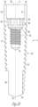
- FIG. 2B illustrates an implant with a cone 105. Note how the first internally facing surface 21 can be present and the anti-rotational means 38 (see FIG. 2A ) is not present.
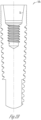
- FIG. 2C illustrates a non-claimed implant without a cone 106. Note that anti-rotational means 38 is present and there is no second internally facing feature 40 (see FIG. 2A ).
- FIG. 3 illustrates a top end view of an implant 5.
- the implant internal bore 20 is continuous with the recess 6 (see FIG. 2A ) which includes an implant first internally facing surface 21 and optionally a second internally facing surface 40.
- the second internally facing surface 40 can include an anti-rotational means 38.
- the implant anti-rotational means 38 can be configured to form a locking connection with an abutment 3 (see FIG. 1 ).
- the internal perimeter 7 of the implant anti-rotational means 38 can take the form of a polygon, such as a hex, a square or other polygonal shape. In an example, the internal perimeter 7 could also take an irregular shape.
- the implant anti-rotational means 38 can also serve a dual purpose as a driving means for installing the implant 5 into a bony structure.
- a second transition zone 29 can be disposed between the apical end of the second internally facing surface 40 and the coronal end of the implant internally threaded portion 22. The second transition zone 29 can help guide the apical end of a fastener 2 (see FIG.1 ) into the internal threads 22 and can be a beveled surface.
- the implant coronal end 18 can include a coronal sealing surface 30 which can be substantially transverse to the longitudinal axis 32 (See FIG. 2A ) of the implant 5.
- the first internally facing surface 21 can be configured to include anti-rotational means and if so, a second internally facing surface 40 may not be present as shown in FIG 2C .
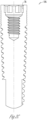
- FIG. 4 is an example of a thread cutting portion 26 on the implant apical end 19.
- the thread cutting portion 26 can be in single, double or multiple configurations disposed around the implant externally facing surface 23.
- FIG. 5 illustrates a side view of an abutment 3 which includes an abutment longitudinal axis 48 and an abutment body 54 extending from the abutment coronal end 49 to the abutment apical end 50.
- the abutment 3 can include a transgingival portion 66 configured to extend through soft gingival tissue, and a supragingival portion 67 configured to extend in the coronal direction beyond the transgingival portion 66 and attach to a prosthetic tooth (not pictured; e.g., a crown).
- the dimensions and shapes of the transgingival portion 66 and the supragingival portion 67 of the abutment 3 can be varied to match the needs of each individual patient. Factors such as the amount of space available and the orientation of the implant can influence the surgeon's decision on the abutment to select when performing a tooth restoration on a patient.
- the abutment 3 includes an external shoulder 53 disposed near the apical end of the transgingival portion 66.
- the apical surface of the external shoulder 53 can be substantially transverse to the longitudinal axis 48 of the abutment body 54.
- the shoulder 53 is configured to engage a coronal sealing surface 30 of an implant 5 (see FIG. 2A ).
- the abutment 3 includes a first externally facing surface 55 positioned between the external shoulder 53 and the abutment apical end 50.
- the first externally facing surface 55 tapers inwardly towards the abutment apical end 50.
- the taper can optionally range from 1-18 degrees. In an example, the taper can optionally range from 1-15 degrees. In an example, the taper can optionally range from 1-12 degrees.
- the taper can optionally range from 1-9 degrees. In an example, the taper can optionally range from 1-6 degrees. In an example, the taper can optionally range from 1-3 degrees. In an example, the taper can optionally range from 3-18 degrees. In an example, the taper can optionally range from 6-18 degrees. In an example, the taper can optionally range from 9-18 degrees. In an example, the taper can optionally range from 12-18 degrees. In an example, the taper can optionally range from 15-18 degrees.
- the abutment can include an abutment anti-rotational means 57 disposed between the apical end of the first externally facing surface 55 and the abutment apical end 50.
- the abutment anti-rotational means 57 can include a polygon 73 or various anti-rotational shapes noted above.
- the abutment anti-rotational means 57 can include a polygon 73 or various anti-rotational shapes noted above.
- the abutment 3 includes an external shoulder 53 disposed near the apical end of the transgingival portion 66.
- the apical surface of the external shoulder 53 can be substantially transverse to the longitudinal axis 48 of the abutment body 54.
- the shoulder 53 is configured to engage a coronal sealing surface 30 of an implant 5 (see FIG. 2A ).
- the abutment 3 can include a first externally facing surface 55 which can be positioned between the external shoulder 53 and the abutment apical end 50.
- the first externally facing surface 55 tapers inwardly towards the abutment apical end 50.
- the taper can optionally range from 1-18 degrees. In an example, the taper can optionally range from 1-15 degrees.
- the taper can optionally range from 1-12 degrees. In an example, the taper can optionally range from 1-9 degrees. In an example, the taper can optionally range from 1-6 degrees. In an example, the taper can optionally range from 1-3 degrees. In an example, the taper can optionally range from 3-18 degrees. In an example, the taper can optionally range from 6-18 degrees. In an example, the taper can optionally range from 9-18 degrees. In an example, the taper can optionally range from 12-18 degrees. In an example, the taper can optionally range from 15-18 degrees.
- the abutment can include an abutment anti-rotational means 57 disposed between the apical end of the first externally facing surface 55 and the abutment apical end 50.
- the abutment anti-rotational means 57 can include a polygon 73 or various anti-rotational shapes noted above.
- the abutment anti-rotational means 57 can include a second externally facing surface 59. At least a portion of the second externally facing surface 59 can be configured to taper inwardly towards the abutment apical end 50.
- the taper can optionally range from 0.2-18 degrees. In an example, the taper can optionally range from 0.2-15 degrees. In an example, the taper can optionally range from 0.2-12 degrees.
- the taper can optionally range from 0.2-9 degrees. In an example, the taper can optionally range from 0.2-6 degrees. In an example, the taper can optionally range from 0.2-3 degrees. In an example, the taper can optionally range from 3-18 surface property. Titanium nitride coating can create a golden, more aesthetically pleasing color on the surface of the abutment as compared with untreated titanium. Portions of the abutment 3, 100, 101, and 102 can also be treated, coated, or roughened to promote soft tissue adhesion or growth in the areas on or adjacent to the treated surfaces.
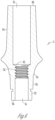
- FIG. 6 illustrates an abutment 3 in cross a sectional view taken from FIG. 5 along line 6-6 and shows the abutment body 54 disposed between the abutment coronal end 49 and the abutment apical end 50.
- An abutment internal bore 51 extends from the abutment coronal end to the abutment apical end 50.
- the abutment internal bore 51 includes an abutment internally threaded portion 52.
- the abutment includes a step portion 43 which can be configured to prevent apical movement of the fastener shoulder surface 15 (see FIG. 1 ).
- the external shoulder 53 is located at the coronal end of the first externally facing surface 55.
- the abutment anti-rotational means 57 can be located near the abutment apical end 50.
- the abutments 100, 101, and 102 of FIGS. 10-12 can have similar cross sections for the elements that are present in these configurations.
- FIG. 7 an apical view of the abutment 3 is shown.
- the transgingival portion 66 can be an area of greatest diameter of the abutment 3.
- the abutment internal bore 51 can pass through the center of the abutment 3.
- the abutment anti-rotational means 57 illustrated are in a hexagonal form, but can be contemplated in any regular or irregular polygonal shape.
- the abutment first externally facing surface 55 can provide a long sealing surface and include an interference fit with an implant.
- FIG. 8 illustrates an assembled dental prosthetic apparatus 1.
- the abutment 3 can be mounted to the dental implant 5 by inserting the base 4 into the recess 6 and then inserting the fastener 2 into the coronal end of the abutment internal bore 51.
- the fastener 2 can be inserted through abutment internal bore 51, with the fastener threads 11 being threaded into an implant internally threaded portion 22 of an implant internal bore 20 of the dental implant 5.
- the fastener 2 can be threaded until the fastener shoulder surface 15 abuts the step 43 of the abutment internal bore 51.
- the fastener 2 can have threads 11 such that the abutment internal threads 52 and implant internal threads 22 are both engaged when the fastener 2 is tightened.
- FIG. 9 is an enlargement view taken from FIG. 8 at 9 -9 and is a close up view of a shoulder connection between the implant 5 and the abutment 3.
- the abutment first externally facing surface 55 is configured to form a first interference fit 34 with the implant first internally facing surface 21.
- This interference fit 34 can form a seal which can prevent a transfer of micro-particles from the internal portions of the dental prosthetic apparatus 1 to the living tissues surrounding it.
- the first interference fit 34 is configured to form a seal in the connection between the abutment first externally facing surface 55 and the implant first internally facing surface 21 substantially simultaneously as the abutment external shoulder 53 seats upon the coronal sealing surface 30 of the implant 5.
- the seating of the external shoulder 53 prevents further apical movement of the abutment first externally facing surface 55 relative to the implant 5.
- the seating of the external shoulder 53 can provide a secondary sealing connection between the abutment 3 and the implant 5.
- the seating of the external shoulder 53 can also prevent cracking in the recess 6 (see FIG. 8 ) of the implant 5 should the tapered connection be over-tightened by the fastener 2 (see FIG. 8 ).
- the fastener 2 can be tightened to the point of stretching. Because the external shoulder 53 limits apical movement of the abutment 3, a stretched fastener can provide additional holding force to prevent the abutment 3 from loosening over time.
- the abutment second externally facing surface 59 can engage the implant second internally facing surface 40.
- the engagement can include abutment anti-rotational means 57 and complementary implant anti-rotational means 38 that further limit movement of the abutment 3 relative to the implant 5 and also provide an indexing means for a surgeon performing a
- the abutment first externally facing surface 55 is configured to form a first interference fit 34 with the implant first internally facing surface 21. This interference fit 34 forms a seal which can prevent a transfer of micro-particles from the internal portions of the dental prosthetic apparatus 1 to the living tissues surrounding it.
- the first interference fit 34 is configured to form a seal in the connection between the abutment first externally facing surface 55 and the implant first internally facing surface 21 substantially simultaneously as the abutment external shoulder 53 seats upon the coronal sealing surface 30 of the implant 5.
- the seating of the external shoulder 53 prevents further apical movement of the abutment first externally facing surface 55 relative to the implant 5.
- the seating of the external shoulder 53 can provide a secondary sealing connection between the abutment 3 and the implant 5.
- the seating of the external shoulder 53 can also prevent cracking in the recess 6 (see FIG. 8 ) of the implant 5 should the tapered connection be over-tightened by the fastener 2 (see FIG. 8 ).
- the fastener 2 can be tightened to the point of stretching. Because the external shoulder 53 limits apical movement of the abutment 3, a stretched fastener can provide additional holding force to prevent the abutment 3 from loosening over time.
- the abutment second externally facing surface 59 can engage the implant second internally facing surface 40.
- the engagement can include abutment anti-rotational means 57 and complementary implant anti-rotational means 38 that further limit movement of the abutment 3 relative to the implant 5 and also provide an indexing means for a surgeon performing a restoration.
- the anti-rotational means may take the form of a polygon, such as a hex shape.
- the engagement of the abutment second externally facing surface 59 and the implant second internally facing surface 40 may be a second interference fit such as at 46.
- the terms “a” or “an” are used to include one or more than one, independent of any other instances or usages of “at least one” or “one or more.”
- the term “or” is used to refer to a nonexclusive or, such that “A or B” includes “A but not B,” “B but not A,” and “A and B,” unless otherwise indicated.
- the terms “about” and “approximately” are used to refer to an amount that is nearly, almost, or in the vicinity of being equal to a stated amount.
- the term “patient” is intended to include mammals, such as for human documents or veterinary documents.
Description
- This application claims the benefit of
U.S. Provisional Patent Application Serial No. 61/801,137, filed on March 15, 2013 - The present patent document pertains generally to the field of dental implants and abutments. The invention disclosed herein can also be applied to other orthopedic applications such as spinal pedicel screws, bone screws used in trauma applications or other bone screws consisting of a three piece assembly (bone screw, adapting head, fastening screw). More particularly, but not by way of limitation, the patent document pertains to an interface between a dental implant and a dental abutment.
- A dental implant can be used in an oral treatment procedure to restore appearance or function of a removed tooth. A dental implant can mimic a root of a natural tooth that is replaced. A surgeon can replace the natural tooth with a prosthetic tooth that is mounted on a coronal portion of an abutment, which in turn, is attached to the dental implant on an apical portion. During surgery, the surgeon can insert the dental implant into a dental bone cavity. A successful dental implant procedure generally requires more than bone affixation or osseointegration. Implant success can also require maintenance of the cortical bone at the coronal crest of the implant and maintenance of soft tissue structures in the implant region. The health of tissues in this region contributes to the aesthetic appearance of a full restoration. Maintenance of healthy tissue in the implant region can also lead to the creation of a tissue seal that hinders the propagation of infection along the implant body.
US 2007/037123 andUS 2012/295223 refer to dental abutments and implants. - In both natural teeth and dental implants, ectodermal tissue serves to protect against intrusion of bacteria and other foreign materials. An ectodermal tissue seal that protects the alveolar bone is known as the biologic width. The biologic width is a tissue ring and its position is dependent on the geometry and surgical placement of the dental implant. On a two-piece dental prosthesis, a micro-gap generally exists between the implant and the abutment. There is evidence to suggest that the position of the micro-gap has an effect on the position of the biologic width, and therefore on the height of the crestal alveolar bone.
- Additional evidence suggests the both vertical and horizontal offset of the micro-gap can contribute to crestal bone height. By offsetting the micro-gap away from the outer edges of the implant, crestal bone height can be maintained. However, such offsetting can result in a smaller abutment/implant interface and may compromise the mechanical strength of the restoration. To accomplish such an offset connection, manufacturers have introduced a conical connection between the abutment and the implant.
- A conical connection might use interfacing shallow angle tapers on the abutment and the implant to shift the micro-gap. This connection can create a sealed interface that discourages penetration of bacteria or other foreign substances into a screw thread and other internal features of an implant body. The conical connection, when used alone, can create a spreading force that tends to crack and split the implant.
- The present patent document describes examples that can include any one or combinations of an implant, an abutment, and an implant system. One or more of the described examples can offer the benefit of an offset micro-gap that can maintain the mechanical strength of a device. The examples can include one or more of several features, including but not limited to: 1) a sealing feature, 2) an more of several features, including but not limited to: 1) a sealing feature, 2) an interference fit feature, and 3) a stability feature. Some of the features can work together and overlap in design and structure, and all of the features can optionally be present in each example. Furthermore, each of the features can serve one or more functions. For example, an interference fit feature can also provide a sealing function. The present patent document contemplates using one or more of three design components including: 1) a shoulder and matching engagement surface (shoulder connection); 2) a mating conical taper (conical connection); and 3) a mating anti-rotational means (anti-rotational means connection).
- These three design components can be combined and configured such that at least two of the components are present in each abutment and/or implant of an implant system. An implant system can include an abutment that matches an implant. For example, if the abutment is configured with a shoulder and a conical taper, the implant can be configured with a surface that the shoulder engages and a mating conical taper. If the abutment is configured with a conical taper and an anti-rotational means, the implant can be configured with a conical taper and an anti-rotational means. One example can include all three components in both the implant and the abutment. The components can be combined in ways that can involve changing their function. In an example, the shoulder might provide a large percentage of the stability and a small percentage of the sealing. In another example the shoulder can provide a large percentage of the sealing. In various other examples, the conical tapers can have an interference fit, the anti-rotational means can have an interference fit, and/or both the conical tapers and the anti-rotational means can have an interference fit.
- An interference fit between the abutment and the implant can provide sealing either between mating conical tapers or between mating anti-rotational means portions. Mating conical tapers can be referenced as a conical connection. A mating anti-rotational means connection can be referenced as an anti-rotational means connection. A connection between a shoulder on an abutment and a shoulder engaging surface on an implant can be referenced as a shoulder connection. An interference fit can be provided in either a conical connection or an anti-rotational means connection between the implant and abutment. An interference fit can be provided in both a conical connection and an anti-rotational means connection between the implant and abutment. When both a conical connection and an anti-rotational connection are present and both connections have an interference fit, the implant system can have a greater stability in terms of resistance to tipping and resistance to screw loosening, than an implant with a conical connection alone.
- If the conical connection or the anti-rotational means connection is used alone with a shoulder connection, then an interference fit is required in the conical connection or the anti-rotational means connection. If both the conical connection and the anti-rotational means connection are used together, with the shoulder connection - then an interference fit is only required in one component. When a shoulder connection is used, a shoulder of an abutment can engage a coronal surface of the implant and provide stability. A shoulder connection can also provide an upper limit to any downward movement of the abutment as it is tightened into the implant. In an example when the shoulder is not used, both the conical connection and the anti-rotational means connection can have an interference fit. In an example with both the anti-rotational means connection and conical connection can have an interference fit; additional stability can be provided as well as an additional positioning limit because the two components are both entering into an interference fit simultaneously.
- One existing problem is that without some limit to prevent an abutment from moving too far apically as it is being tightened; there can be the possibility of cracking the implant if there is any taper feature, such as a conical connection. This problem can be overcome in at least two ways: 1) by having an abutment shoulder engaging the implant or 2) by having more than one component with an interference fit that limits apical movement of the abutment as it is tightened.
- Vertical forces, such as bite forces, can be transferred from an abutment to an implant directly though a connection between an abutment and an implant. Such a connection may have connecting surfaces on the abutment and the implant that are substantially perpendicular to the longitudinal axes of the implant and abutment. Bending loads may also be transferred at least in part by bearing along part of the connection. A dental implant is typically a cylinder with the longest dimension oriented parallel to the vertical component of a biting force. Through a connection with a shoulder, compressive loads are transmitted vertically in a direction of the greatest material thickness of the implant.
- An exemplary connection can be a combination of a shoulder connection and an interference fit between some portion of the implant and the abutment. The shoulder connection can offer mechanical strength and a definitive stop, while an interference fit between the abutment and the implant can limit rotation and create a seal with the above mentioned micro-gap offsetting advantages.
- In an example, the interface between an abutment and an implant can include a first element at the apical end of the abutment such as a hexagonal polygon. This polygon can create an anti-rotational interface with a similarly shaped socket in an implant. The polygon can be a friction fit like Zimmer Dental's TSV Hex-Lock® connection. The polygon interface can also provide a way to index prosthetics. An orientation selected to build the prosthetic in a dental laboratory can be relocated when the prosthetic is placed in the patient.
- A second element of the combined connection between the implant and abutment can be located adjacent and coronal to the polygon, such as a conical taper. This element can feature a gradual taper that decreases in diameter in the apical direction. The angle of the taper can be in a range between about 1° and about 18°. This selection can assure that a tapered element of the abutment extends deep into a mating receptacle on the implant. The implant receptacle can also be conical and very close in angulations to the abutment cone. In this manner the two cones can have a longer area of engagement or interference where sealing can occur.
- Benefits of a long engagement of the tapered seal can include, for example: 1) stability between the implant and abutment; and 2) a seal that can prevent the exchange of fluids that may contain bacteria and other pathogens between the inside chamber of the implant and the outside environment. A phenomenon known as micro-pumping can transfer bacteria that have incubated inside of the implant onto soft and hard tissue adjacent to the implant. Micro-pumping can have a detrimental effect on tissue in an implant region and on the success of the implant restoration.
- A shoulder connection can have a shoulder that is oriented substantially perpendicular to the long access of the implant body and can create a substantially flat connection between the implant and the abutment. This flat connection can utilize the increased material thickness of the long axis to resist tipping forces.
- Another stable connection can be configured by having both a conical connection and an anti-rotational connection that are both tapered and have interference fits. This type of connection can be much more stable than a connection with only a conical connection. In a connection with only a conical connection, under sufficient loading, mating cones can act like a ball and socket joint and can be ineffective in preventing tipping (rotation perpendicular to the long axis) of an abutment.
- A flat shoulder connection between the implant and the abutment can also create a definite stop that can limit a cone to cone interference connection and therefore limit an outward force and hoop stress created by the cone to cone interference connection. In another example there can be an interference fit between the anti-rotational means, and providing the shoulder connection can allow for more precise control of the interference fit at this connection. For example, in a hexagonal polygon anti-rotational element, the hex can be seated to virtually eliminate rotational micro-movement without becoming over stressed.
- A retaining fastener can connect an implant and an abutment. A high degree of retaining fastener pre-load can be assured by the combination connection of a conical connection and a shoulder connection. When the shoulder connection seats, for example if a shoulder on the abutment contacts a mating surface of the implant, the vertical motion of the abutment can be prevented. At this point a full torque applied to the fastener can act to stretch the fastener shaft. This stretching of the fastener shaft can store energy, which can maintain a clamping force that prevents the fastener from loosening.
- It can be important to set taper diameters and angles of the implant and abutment correctly to provide a sufficient seal between tapers and engage mating anti-rotational elements just prior to seating the shoulder connection. Seating the shoulder connection sets a precise and known height of abutment features for an implant interface. Additional fastener tightening to a predetermined torque value can establish a precise fastener preload. When a shoulder connection is used, the taper in either or both of the conical connection or the anti-rotational means connection can be designed so that as the interference fit acquires the proper pre-load, the shoulder connection simultaneously forms a tight seal.
- A precise and known abutment seating height can be important clinically. Typically, the tooth prosthetic is made in a dental laboratory on an implant analog in a dental model and then transferred to a patient. Differences in a vertical seating height between the abutment in the analog and the abutment in the implant can result in aesthetic or even functional problems with the restoration.
- The advantages of the described combination connection can be numerous but creating such a connection may require precise selection of the dimensions and tolerances of one or more of the three components (i.e., the conical connection, the anti-rotational means connection and the shoulder connection). Other examples of the present patent document where the implant recess and abutment mating features are reversed or where the anti-rotational interface is of another geometry or excluded entirely are possible and are contemplated by this specification.
- This Overview is intended to provide an overview of subject matter of the present patent document. It is not intended to provide an exclusive or exhaustive explanation of the invention. The detailed description is included to provide further information about the present patent document.
- Accordingly, the invention provides , a dental abutment for use with a dental implant comprising an abutment body having a longitudinal axis, a coronal end, and an apical end, wherein the abutment body includes a first externally facing surface, extending from a location between the coronal end and the apical end and towards the apical end, at least a portion of which tapers conically inwardly towards the apical end; an internal bore provided within the abutment body, at least a portion of the internal bore having internal threads; an external shoulder positioned between a coronal end of the first externally facing surface and the coronal end of the abutment body and a step portion located between the abutment coronal end and the abutment internal threads wherein the conically tapered portion of the first externally facing surface of the abutment forms an interference fit when in use with a mating conically tapered recess in the dental implant.
- The dental abutment can optionally be configured such that the first externally facing surface includes an anti-rotation feature.
- The dental abutment can optionally be configured such that the anti-rotation feature includes a polygon-shaped external perimeter.
- The dental abutment can optionally be configured to further comprise an anti-rotation feature positioned between an apical end of the first externally facing surface and the apical end of the abutment body.
- The dental abutment can optionally be configured such that the anti-rotation feature includes a polygon-shaped external perimeter.
- The dental abutment can optionally be configured such that the anti-rotation feature
defines a second externally facing surface of the abutment body, at least a portion of the second externally facing surface tapered inwardly towards the apical end of the abutment body. - The invention provides a dental implant system comprising an abutment as defined in
claims 1 to 6 and an implant comprising: an implant body having a longitudinal axis, a coronal end, and an apical end; an implant internal bore, provided within the implant body, having a coronal end adjacent to the coronal end of the implant body and an apical end; a first internally facing surface extending from the coronal end of the implant internal bore towards the apical end of the implant internal bore, at least a portion of the first internally facing surface being conically tapered inwardly towards the apical end of the implant internal bore; and an internally threaded portion positioned within the implant internal bore between an apical end of the first internally facing surface and the apical end of the implant internal bore. The dental implant system can further comprise a fastener insertable within the internal bore of the abutment and configured to engage the internally threaded portion of the abutment and the internally threaded portion of the implant. - The dental implant system can optionally be configured such that the first internally facing surface of the implant is configured to form an interference fit with the first externally facing surface of the abutment.
- The dental implant system can optionally be configured such that the first internally facing surface of the implant includes an implant anti-rotation feature configured to mate with an abutment anti-rotation feature included in the first externally facing surface of the abutment, and wherein the implant anti-rotation feature includes a polygon-shaped internal perimeter and the abutment anti-rotation feature includes a polygon-shaped external perimeter.
- The dental implant system can optionally be configured to further comprise an implant anti-rotation feature disposed within the implant internal bore between the apical end of the first internally facing surface and a coronal end of the implant internally threaded portion; and an abutment anti-rotation feature disposed between an apical end of the first externally facing surface of the abutment body and the apical end of the abutment body, wherein the implant anti-rotation feature is configured to mate with the abutment anti-rotation feature to inhibit rotation of the implant relative to the abutment.
- The dental implant system can optionally be configured such that the implant anti-rotation feature includes a polygon-shaped internal perimeter and the abutment anti-rotation feature includes a polygon-shaped external perimeter.
- The dental implant system can optionally be configured such that the implant anti-rotation feature defines a second internally facing surface of the implant internal bore, at least a portion of the second internally facing surface of the implant internal bore being tapered inwardly towards the apical end of the implant internal bore, and wherein the abutment anti-rotation feature defines a second externally facing surface of the abutment body, at least a portion of the second externally facing surface of the abutment body being tapered inwardly towards the apical end of the abutment body.
- In the drawings, which are not necessarily drawn to scale, like numerals may describe similar components in different views. Like numerals having different letter suffixes may represent different instances of similar components. The drawings illustrate generally, by way of example, but not by way of limitation, various embodiments discussed in the present document.
-
FIG. 1 is an isometric exploded view of the dental implant system showing a fastener, an abutment and an implant. -
FIG. 2A is a cross-sectional side view of an implant in accordance with the present patent document. -
FIG. 2B is a cross-sectional side view of a non-claimed implant in accordance with the present patent document. -
FIG. 2C is a cross-sectional side view of an implant. -
FIG. 3 is a coronal end view of the implant ofFIG. 2A . -
FIG. 4 is a partial side view of the implant ofFIG. 2A showing an implant retaining means in accordance with the present patent document. -
FIG. 5 is a side view of an abutment in accordance with the present patent document. -
FIG. 6 is a cross-sectional side view of the abutment ofFIG. 5 . -
FIG. 7 is an apical end view of the abutment ofFIG. 5 . -
FIG. 8 is a cross sectional view of the assembled implant, abutment and fastener. -
FIG. 2A is a cross-sectional side view of an implant in accordance with the present patent document. -
FIG. 2B is a cross-sectional side view of an implant in accordance with the present patent document. -
FIG. 2C is a cross-sectional side view of an implant in accordance with the present patent document. -
FIG. 3 is a coronal end view of the implant ofFIG. 2A . -
FIG. 4 is a partial side view of the implant ofFIG. 2A showing an implant retaining means in accordance with the present patent document. -
FIG. 5 is a side view of an abutment in accordance with the present patent document. -
FIG. 6 is a cross-sectional side view of the abutment ofFIG. 5 . -
FIG. 7 is an apical end view of the abutment ofFIG. 5 . -
FIG. 8 is a cross sectional view of the assembled implant, abutment and fastener. -
FIG. 9 is an enlarged fragmentary view of the connection between the abutment and implant. -
FIG. 10 is a side view of an abutment in accordance with the present patent document. -
FIG. 11 is a side view of a non-claimed abutment. -
FIG. 12 is a side view of an abutment in accordance with the present patent document. - It can be desirable to offset a seal connection between a dental implant and a dental abutment inwardly and apically from the outer surfaces of an implant/abutment connection. A tapered connection between the implant and abutment can accomplish moving the sealing connection in this manner. Proper engineering of the length of the tapers and angle of the tapers can produce the tightest fit at a desired location in a tapered connection. The combination of a correctly placed shoulder connection and a tapered connection to an implant/abutment connection can provide stability and strength to the connection as well as an additional sealing surface. The shoulder connection is accomplished by using an external shoulder on the abutment to engage a mating surface on the implant. The interaction between the implant and abutment tapers for the conical connection and the placement of the shoulder can be precise to provide the proper preload on both the conical connection seal and the shoulder seal. The shoulder provides an exact vertical limit to the apical movement of the abutment as it is tightened down into the implant by a connecting fastener. This limit provides two advantages: it prevents the abutment cone from over stressing the implant conical features and it provides a repeatable vertical placement of the abutment. An additional advantage is that a fastener can be torqued to the point of stretching the fastener. The vertical height of the abutment will remain fixed because of the shoulder limit and the stretched fastener will provide added stability to the connection. The shoulder connection is used in conjunction with a conical connection or in conjunction with both a conical connection and an anti-rotational means connection. connections together. Another example which can provide added stability is a connection having both an interference fit conical connection and an interference fit anti-rotational connection.
- In the following description
FIGS. 1 ,2A , and3 -9 describe examples containing all three of the components mentioned above, the shoulder connection, the conical connection elements and the anti-rotational means connection features.FIGS. 2B ,2C , and10 -12 describe examples containing only two of the three components and it should be understood that the more detailed description of the elements ofFIGS. 1 ,2A , and3 -9 can also apply to the examples described inFIGS. 2B ,2C , and10 -12. -
FIG. 1 illustrates an example of a dentalprosthetic apparatus 1 including adental implant 5, anabutment 3, and a connecting fastener 2. The dentalprosthetic apparatus 1 can provide an anchor for a prosthetic tooth (e.g., a crown) in an oral site where teeth are damaged or missing. Theabutment 3 can include a base 4 configured to mate with thedental implant 5. The base 4 can be compared to features at the apical end of theabutment 3 and can vary (seeFIGS. 5 ,10 ,11 ,12 ). The base 4 can be frictionally retained by a similarly-shapedrecess 6 formed in thedental implant 5. In an example, the base 4 can have a polygonal exterior surface including a plurality of flat surfaces. The base 4 can be an anti-rotational component. Therecess 6 in thedental implant 5 can include a polygonal shaped internal perimeter 7 (seeFIG. 3 ) including a plurality of generally flat surfaces configured to mate with the base 4 of theabutment 3. - The fastener 2 can include a
longitudinal axis 8 extending between a fastener coronal end 9 and a fastenerapical end 10. The fastener can havefastener threads 11 extending towards the fastenerapical end 10. The fastener can include a shank portion 12 that is unthreaded between afastener head 13 and the fastenerapical end 10. Thefastener head 13 can have a drive means 14 which could include a slotted form, a hex form, a torx form, a Phillips head form or any other driving means form. On the apical end of thefastener head 13, the fastener 2 can include afastener shoulder surface 15 which is substantially transverse to thelongitudinal axis 8 of the fastener 2. In another example thefastener shoulder surface 15 can be a beveled surface. -
FIG. 2A illustrates adental implant 5 in cross section. Thedental implant 5 can be fitted into a dental cavity formed in a patient's dental bone. Thedental implant 5 can include acollar portion 16. Thecollar portion 16 can be the portion of thedental implant 5 forming therecess 6 in which the base 4 (SeeFIG. 1 ) of the abutment is inserted. The exterior surface of thecollar portion 16 can be threaded, partially threaded, ridged, non-threaded, or saw toothed, the latter of which is pictured inFIG. 2A . Thecollar portion 16 may not be present in all examples. - The
dental implant 5 can include a longitudinally extendingimplant body 17, having acoronal end 18 and anapical end 19, adapted to be implanted into a dental cavity formed in the dental bone of a patient. The dental cavity can be formed according to known surgical techniques, for example, by a surgeon drilling into a patient's jaw bone at an edentulous site. Theimplant body 17 can include an externally facingsurface 23 for interacting with bone tissue, thereby securing thedental implant 5 to the dental bone through osseointegration or other biological or mechanical interactions. Theimplant body 17 can be made of a biocompatible metal, for example, titanium or other biocompatible material such as polymer or ceramic. - The
implant body 17 can be cylindrical, partially cylindrical, or tapered in shape. Theimplant body 17 can include an implantinternal bore 20 extending from thecoronal end 18 to anapical termination point 24, such as is illustrated inFIG. 2A . The implantinternal bore 20 includes an implant internally threadedportion 22 configured to interact with thefastener threads 11 of the fastener 2 to secure theabutment 3 to the dental implant 5 (SeeFIG. 1 ). Theimplant body 17 may include the whole length of theimplant 5 or a portion of it. - The
dental implant 5 can include continuous or discreteexternal threads 25 along a portion or whole of the implant externally facingsurface 23. Theexternal threads 25 can be in the form of single, double or multiple helical threads. To facilitate osseointegration, portions of the implant externally facingsurface 23 can include a porous biomaterial useful as a bone substitute or cell and tissue receptive material. Additionally, portions of the externally facingsurface 23 can be provided with a porous and osteo-inductive coating, such as hydroxylapatite. - Highly porous biomaterials can be called highly biocompatible materials. Highly biocompatible materials can include porous metallic structures such as porous tantalum, porous titanium, porous cobalt chrome, or porous zirconia dioxide, as well as polymeric scaffolds, or porous sections of the aforementioned materials incorporating bone morphogenic proteins, platelet rich plasma, allografts, xenografts, autografts, or probiotic bacteria.
- At the coronal end of the implant, the
recess 6 can be continuous with the implantinternal bore 20. Thecoronal end 18 can include acoronal sealing surface 30 which can be substantially perpendicular to thelongitudinal axis 32 of theimplant 5. Therecess 6 has a first internally facingsurface 21 and optionally a second internally facingsurface 40. The first internally facingsurface 21 is tapered inwardly towards the implantapical end 19. The taper can optionally range from 1-18 degrees. In an example, the taper can optionally range from 1-15 degrees. In an example, the taper can optionally range from 1-12 degrees. In an example, the taper can optionally range from 1-9 degrees. In an example, the taper can optionally range from 1-6 degrees. In an example, the taper can optionally range from 1-3 degrees. In an example, the taper can optionally range from 3-18 degrees. In an example, the taper can optionally range from 6-18 degrees. In an example, the taper can optionally range from 9-18 degrees. In an example, the taper can optionally range from 12-18 degrees. In an example, the taper can optionally range from 15-18 degrees. - At the apical end of the first internally facing
surface 21 there can be afirst transition zone 28 which can form a gradual change in morphology between the apical end of the first internally facingsurface 21 and the coronal end of the second internally facingsurface 40. The second internally facingsurface 40 can include an implant anti-rotational means 38 which can be designed to engage with an abutment anti-rotational means 57 (SeeFIG. 5 ). The anti-rotational means could comprise mating polygonal shapes, mating slotted structures having one or more keyways, mating lobed structures, or any other type of mating structures which resist rotational movement when the mating structures of the abutment and implant are combined. The second internally facingsurface 40 can be tapered inwardly towards the implantapical end 19. The taper can optionally range from 0.2-18 -
FIG. 2B illustrates an implant with acone 105. Note how the first internally facingsurface 21 can be present and the anti-rotational means 38 (seeFIG. 2A ) is not present. -
FIG. 2C illustrates a non-claimed implant without acone 106. Note that anti-rotational means 38 is present and there is no second internally facing feature 40 (seeFIG. 2A ). -
FIG. 3 illustrates a top end view of animplant 5. The implantinternal bore 20 is continuous with the recess 6 (seeFIG. 2A ) which includes an implant first internally facingsurface 21 and optionally a second internally facingsurface 40. The second internally facingsurface 40 can include an anti-rotational means 38. The implant anti-rotational means 38 can be configured to form a locking connection with an abutment 3 (seeFIG. 1 ). The internal perimeter 7 of the implant anti-rotational means 38 can take the form of a polygon, such as a hex, a square or other polygonal shape. In an example, the internal perimeter 7 could also take an irregular shape. The implant anti-rotational means 38 can also serve a dual purpose as a driving means for installing theimplant 5 into a bony structure. Asecond transition zone 29 can be disposed between the apical end of the second internally facingsurface 40 and the coronal end of the implant internally threadedportion 22. Thesecond transition zone 29 can help guide the apical end of a fastener 2 (seeFIG.1 ) into theinternal threads 22 and can be a beveled surface. The implantcoronal end 18 can include acoronal sealing surface 30 which can be substantially transverse to the longitudinal axis 32 (SeeFIG. 2A ) of theimplant 5. The first internally facingsurface 21 can be configured to include anti-rotational means and if so, a second internally facingsurface 40 may not be present as shown inFIG 2C . -
FIG. 4 is an example of athread cutting portion 26 on the implantapical end 19. Thethread cutting portion 26 can be in single, double or multiple configurations disposed around the implant externally facingsurface 23. -
FIG. 5 illustrates a side view of anabutment 3 which includes an abutment longitudinal axis 48 and anabutment body 54 extending from the abutmentcoronal end 49 to the abutmentapical end 50. Theabutment 3 can include atransgingival portion 66 configured to extend through soft gingival tissue, and asupragingival portion 67 configured to extend in the coronal direction beyond thetransgingival portion 66 and attach to a prosthetic tooth (not pictured; e.g., a crown). The dimensions and shapes of thetransgingival portion 66 and thesupragingival portion 67 of theabutment 3 can be varied to match the needs of each individual patient. Factors such as the amount of space available and the orientation of the implant can influence the surgeon's decision on the abutment to select when performing a tooth restoration on a patient. - The
abutment 3 includes anexternal shoulder 53 disposed near the apical end of thetransgingival portion 66. The apical surface of theexternal shoulder 53 can be substantially transverse to the longitudinal axis 48 of theabutment body 54. Theshoulder 53 is configured to engage acoronal sealing surface 30 of an implant 5 (seeFIG. 2A ). Theabutment 3 includes a first externally facingsurface 55 positioned between theexternal shoulder 53 and the abutmentapical end 50. The first externally facingsurface 55 tapers inwardly towards the abutmentapical end 50. The taper can optionally range from 1-18 degrees. In an example, the taper can optionally range from 1-15 degrees. In an example, the taper can optionally range from 1-12 degrees. In an example, the taper can optionally range from 1-9 degrees. In an example, the taper can optionally range from 1-6 degrees. In an example, the taper can optionally range from 1-3 degrees. In an example, the taper can optionally range from 3-18 degrees. In an example, the taper can optionally range from 6-18 degrees. In an example, the taper can optionally range from 9-18 degrees. In an example, the taper can optionally range from 12-18 degrees. In an example, the taper can optionally range from 15-18 degrees. - The abutment can include an abutment anti-rotational means 57 disposed between the apical end of the first externally facing
surface 55 and the abutmentapical end 50. The abutment anti-rotational means 57 can include a polygon 73 or various anti-rotational shapes noted above. The abutment anti- - The
abutment 3 includes anexternal shoulder 53 disposed near the apical end of thetransgingival portion 66. The apical surface of theexternal shoulder 53 can be substantially transverse to the longitudinal axis 48 of theabutment body 54. Theshoulder 53 is configured to engage acoronal sealing surface 30 of an implant 5 (seeFIG. 2A ). Theabutment 3 can include a first externally facingsurface 55 which can be positioned between theexternal shoulder 53 and the abutmentapical end 50. The first externally facingsurface 55 tapers inwardly towards the abutmentapical end 50. The taper can optionally range from 1-18 degrees. In an example, the taper can optionally range from 1-15 degrees. In an example, the taper can optionally range from 1-12 degrees. In an example, the taper can optionally range from 1-9 degrees. In an example, the taper can optionally range from 1-6 degrees. In an example, the taper can optionally range from 1-3 degrees. In an example, the taper can optionally range from 3-18 degrees. In an example, the taper can optionally range from 6-18 degrees. In an example, the taper can optionally range from 9-18 degrees. In an example, the taper can optionally range from 12-18 degrees. In an example, the taper can optionally range from 15-18 degrees. - The abutment can include an abutment anti-rotational means 57 disposed between the apical end of the first externally facing
surface 55 and the abutmentapical end 50. The abutment anti-rotational means 57 can include a polygon 73 or various anti-rotational shapes noted above. The abutment anti-rotational means 57 can include a second externally facingsurface 59. At least a portion of the second externally facingsurface 59 can be configured to taper inwardly towards the abutmentapical end 50. The taper can optionally range from 0.2-18 degrees. In an example, the taper can optionally range from 0.2-15 degrees. In an example, the taper can optionally range from 0.2-12 degrees. In an example, the taper can optionally range from 0.2-9 degrees. In an example, the taper can optionally range from 0.2-6 degrees. In an example, the taper can optionally range from 0.2-3 degrees. In an example, the taper can optionally range from 3-18 surface property. Titanium nitride coating can create a golden, more aesthetically pleasing color on the surface of the abutment as compared with untreated titanium. Portions of theabutment -
FIG. 6 illustrates anabutment 3 in cross a sectional view taken fromFIG. 5 along line 6-6 and shows theabutment body 54 disposed between the abutmentcoronal end 49 and the abutmentapical end 50. An abutmentinternal bore 51 extends from the abutment coronal end to the abutmentapical end 50. The abutmentinternal bore 51 includes an abutment internally threadedportion 52. Between the abutmentcoronal end 49 and the abutment internally threadedportion 52, the abutment includes astep portion 43 which can be configured to prevent apical movement of the fastener shoulder surface 15 (seeFIG. 1 ). Theexternal shoulder 53 is located at the coronal end of the first externally facingsurface 55. The abutment anti-rotational means 57 can be located near the abutmentapical end 50. Theabutments FIGS. 10-12 can have similar cross sections for the elements that are present in these configurations. - In
FIG. 7 an apical view of theabutment 3 is shown. Thetransgingival portion 66 can be an area of greatest diameter of theabutment 3. The abutmentinternal bore 51, can pass through the center of theabutment 3. The abutment anti-rotational means 57 illustrated are in a hexagonal form, but can be contemplated in any regular or irregular polygonal shape. The abutment first externally facingsurface 55 can provide a long sealing surface and include an interference fit with an implant. -
FIG. 8 illustrates an assembled dentalprosthetic apparatus 1. Theabutment 3 can be mounted to thedental implant 5 by inserting the base 4 into therecess 6 and then inserting the fastener 2 into the coronal end of the abutmentinternal bore 51. The fastener 2 can be inserted through abutmentinternal bore 51, with thefastener threads 11 being threaded into an implant internally threadedportion 22 of an implantinternal bore 20 of thedental implant 5. The fastener 2 can be threaded until thefastener shoulder surface 15 abuts thestep 43 of the abutmentinternal bore 51. In another example the fastener 2 can havethreads 11 such that the abutmentinternal threads 52 and implantinternal threads 22 are both engaged when the fastener 2 is tightened. -
FIG. 9 is an enlargement view taken fromFIG. 8 at 9 -9 and is a close up view of a shoulder connection between theimplant 5 and theabutment 3. The abutment first externally facingsurface 55 is configured to form afirst interference fit 34 with the implant first internally facingsurface 21. This interference fit 34 can form a seal which can prevent a transfer of micro-particles from the internal portions of the dentalprosthetic apparatus 1 to the living tissues surrounding it. - The
first interference fit 34 is configured to form a seal in the connection between the abutment first externally facingsurface 55 and the implant first internally facingsurface 21 substantially simultaneously as the abutmentexternal shoulder 53 seats upon thecoronal sealing surface 30 of theimplant 5. The seating of theexternal shoulder 53 prevents further apical movement of the abutment first externally facingsurface 55 relative to theimplant 5. The seating of theexternal shoulder 53 can provide a secondary sealing connection between theabutment 3 and theimplant 5. The seating of theexternal shoulder 53 can also prevent cracking in the recess 6 (seeFIG. 8 ) of theimplant 5 should the tapered connection be over-tightened by the fastener 2 (seeFIG. 8 ). Once theexternal shoulder 53 has seated on thecoronal sealing surface 30, the fastener 2 can be tightened to the point of stretching. Because theexternal shoulder 53 limits apical movement of theabutment 3, a stretched fastener can provide additional holding force to prevent theabutment 3 from loosening over time. - Returning to
FIG. 8 , the abutment second externally facingsurface 59 can engage the implant second internally facingsurface 40. The engagement can include abutment anti-rotational means 57 and complementary implant anti-rotational means 38 that further limit movement of theabutment 3 relative to theimplant 5 and also provide an indexing means for a surgeon performing a The abutment first externally facingsurface 55 is configured to form afirst interference fit 34 with the implant first internally facingsurface 21. This interference fit 34 forms a seal which can prevent a transfer of micro-particles from the internal portions of the dentalprosthetic apparatus 1 to the living tissues surrounding it. - The
first interference fit 34 is configured to form a seal in the connection between the abutment first externally facingsurface 55 and the implant first internally facingsurface 21 substantially simultaneously as the abutmentexternal shoulder 53 seats upon thecoronal sealing surface 30 of theimplant 5. The seating of theexternal shoulder 53 prevents further apical movement of the abutment first externally facingsurface 55 relative to theimplant 5. The seating of theexternal shoulder 53 can provide a secondary sealing connection between theabutment 3 and theimplant 5. The seating of theexternal shoulder 53 can also prevent cracking in the recess 6 (seeFIG. 8 ) of theimplant 5 should the tapered connection be over-tightened by the fastener 2 (seeFIG. 8 ). Once theexternal shoulder 53 has seated on thecoronal sealing surface 30, the fastener 2 can be tightened to the point of stretching. Because theexternal shoulder 53 limits apical movement of theabutment 3, a stretched fastener can provide additional holding force to prevent theabutment 3 from loosening over time. - Returning to
FIG. 8 , the abutment second externally facingsurface 59 can engage the implant second internally facingsurface 40. The engagement can include abutment anti-rotational means 57 and complementary implant anti-rotational means 38 that further limit movement of theabutment 3 relative to theimplant 5 and also provide an indexing means for a surgeon performing a restoration. The anti-rotational means may take the form of a polygon, such as a hex shape. The engagement of the abutment second externally facingsurface 59 and the implant second internally facingsurface 40 may be a second interference fit such as at 46. - The above Detailed Description includes references to the accompanying drawings, which form a part of the Detailed Description. The drawings show, by way of illustration, specific embodiments in which the present dental implant can be practiced. These embodiments are also referred to herein as "examples."
- The above Detailed Description is intended to be illustrative, and not restrictive.
- In this document, the terms "a" or "an" are used to include one or more than one, independent of any other instances or usages of "at least one" or "one or more." In this document, the term "or" is used to refer to a nonexclusive or, such that "A or B" includes "A but not B," "B but not A," and "A and B," unless otherwise indicated. In this document, the terms "about" and "approximately" are used to refer to an amount that is nearly, almost, or in the vicinity of being equal to a stated amount. In this document, the term "patient" is intended to include mammals, such as for human documents or veterinary documents.
- In the appended claims, the terms "including" and "in which" are used as the plain-English equivalents of the respective terms "comprising" and "wherein." Also, in the following claims, the terms "including" and "comprising" are open-ended, that is, an implant, assembly, kit, or method that includes elements in addition to those listed after such a term in a claim are still deemed to fall within the scope of that claim. Moreover, in the following claims, the terms "first," "second," and "third," etc. are used merely as labels, and are not intended to impose numerical requirements on their objects.
- The Abstract is provided to allow the reader to quickly ascertain the nature of the technical disclosure. It is submitted with the understanding that it will not be used to interpret or limit the scope or meaning of the claims.
Claims (13)
- A dental abutment (3) for use with a dental implant (5), comprising:an abutment body (54) having a longitudinal axis (48), a coronal end (49), and an apical end (50), wherein the abutment body includes a first externally facing surface (55), extending from a location between the coronal end (49) and the apical end (50) and towards the apical end (50), at least a portion of which tapers conically inwardly towards the apical end (50);an internal bore (51) provided within the abutment body (54), at least a portion of the internal bore having internal threads (52);an external shoulder (53) positioned between a coronal end of the first externally facing surface and the coronal end of the abutment body anda step portion (43) located between the abutment coronal end (49) and the abutment internal threads (52),wherein the conically tapered portion of the first externally facing surface (55) of the abutment (3) is able to form an interference fit (34) when in use with a mating conically tapered recess in the dental implant.
- The dental abutment (3) of claim 1, wherein the first externally facing surface (55) includes an anti-rotation feature (57).
- The dental abutment (3) of claim 2, wherein the anti-rotation feature (57) includes a polygon-shaped external perimeter.
- The dental abutment (3) of claim 1, further comprising an anti-rotation feature positioned between an apical end of the first externally facing surface and the apical end of the abutment body.
- The dental abutment (3) of claim 4, wherein the anti-rotation feature includes a polygon-shaped external perimeter.
- The dental abutment (3) of claim 4, wherein the anti-rotation feature defines a second externally facing surface of the abutment body, at least a portion of the second externally facing surface tapered inwardly towards the apical end of the abutment body.
- A dental implant system comprising an abutment (3) as claimed in any of claims 1 to 6 and a dental implant comprising:an implant body having a longitudinal axis, a coronal end, and an apical end, the coronal end of the implant body including an externally facing surface oriented substantially transverse to the longitudinal axis and structured to be engagable to an external shoulder portion of an abutment; andan internal bore, provided within the implant body, having a coronal end adjacent to the coronal end of the implant body and an apical end,the internal bore including a first internally facing surface, extending from the coronal end of the internal bore towards the apical end of the internal bore, at least a portion of which tapers conically inwardly towards the apical end of the internal bore, andthe internal bore further including an internally threaded portion positioned between an apical end of the first internally facing surface and the apical end of the internal bore.
- The dental implant system of claim 7, wherein the first internally facing surface is configurable to form an interference fit with an abutment.
- The dental implant system of any one of claims 7-8, wherein the first internally facing surface includes an anti-rotation feature.
- The dental implant system of claim 9, wherein the anti-rotation feature includes a polygon-shaped internal perimeter.
- The dental implant system of any one of claims 7-8, further comprising an anti-rotation feature disposed within the internal bore, between the apical end of the first internally facing surface and a coronal end of the internally threaded portion.
- The dental implant system of claim 11, wherein the anti-rotation feature includes a polygon-shaped internal perimeter.
- The dental implant system of claim 12, wherein the anti-rotation feature defines a second internally facing surface of the internal bore, at least a portion of the second internally facing surface being tapered inwardly towards the apical end of the internal bore.
Applications Claiming Priority (3)
| Application Number | Priority Date | Filing Date | Title |
|---|---|---|---|
| US201361801137P | 2013-03-15 | 2013-03-15 | |
| EP14714892.8A EP2967761B1 (en) | 2013-03-15 | 2014-03-12 | Dental implant with improved prosthetic interface |
| PCT/US2014/024046 WO2014150713A1 (en) | 2013-03-15 | 2014-03-12 | Dental implant with improved prosthetic interface |
Related Parent Applications (1)
| Application Number | Title | Priority Date | Filing Date |
|---|---|---|---|
| EP14714892.8A Division EP2967761B1 (en) | 2013-03-15 | 2014-03-12 | Dental implant with improved prosthetic interface |
Publications (2)
| Publication Number | Publication Date |
|---|---|
| EP3821847A1 EP3821847A1 (en) | 2021-05-19 |
| EP3821847B1 true EP3821847B1 (en) | 2024-03-27 |
Family
ID=50424774
Family Applications (2)
| Application Number | Title | Priority Date | Filing Date |
|---|---|---|---|
| EP20177859.4A Active EP3821847B1 (en) | 2013-03-15 | 2014-03-12 | Dental implant with improved prosthetic interface |
| EP14714892.8A Active EP2967761B1 (en) | 2013-03-15 | 2014-03-12 | Dental implant with improved prosthetic interface |
Family Applications After (1)
| Application Number | Title | Priority Date | Filing Date |
|---|---|---|---|
| EP14714892.8A Active EP2967761B1 (en) | 2013-03-15 | 2014-03-12 | Dental implant with improved prosthetic interface |
Country Status (7)
| Country | Link |
|---|---|
| US (2) | US10813724B2 (en) |
| EP (2) | EP3821847B1 (en) |
| CN (1) | CN105208965B (en) |
| AU (2) | AU2014235703B2 (en) |
| CA (1) | CA2905383C (en) |
| ES (1) | ES2798117T3 (en) |
| WO (1) | WO2014150713A1 (en) |
Families Citing this family (21)
| Publication number | Priority date | Publication date | Assignee | Title |
|---|---|---|---|---|
| DE112013001333T5 (en) * | 2012-03-08 | 2014-11-20 | James R. Glidewell Dental Ceramics, Inc. | Prefabricated ceramic dental implant abutment for a counter ceramic prosthetic abutment construction |
| EP3821847B1 (en) | 2013-03-15 | 2024-03-27 | Zimmer Dental Inc. | Dental implant with improved prosthetic interface |
| IL230833A0 (en) * | 2014-02-05 | 2014-09-30 | Ophir Fromovich | Bone implant anchor |
| US10743966B2 (en) * | 2015-01-21 | 2020-08-18 | Kwang Seob Kim | Implant unit |
| BR102016010184B1 (en) * | 2016-05-05 | 2020-10-27 | Jjgc Indústria E Comércio De Materiais Dentários S.A. | prosthetic set and process for producing the same |
| CH712894A2 (en) * | 2016-09-08 | 2018-03-15 | Dentalpoint Ag | Dentures system. |
| SE539676C2 (en) * | 2016-11-08 | 2017-10-31 | Integrum Ab | Anchoring system for attaching a prosthesis to a human body |
| IT201700016540A1 (en) * | 2017-02-15 | 2018-08-15 | Permedica S P A | Dental implant |
| US11273020B2 (en) * | 2017-06-13 | 2022-03-15 | Biomet 3I, Llc | Implant analogs and methods |
| US20180353267A1 (en) | 2017-06-13 | 2018-12-13 | Biomet 3I, Llc | Combination impression coping and scan body |
| IT201700076961A1 (en) * | 2017-07-07 | 2019-01-07 | Plan 1 Health Srl | DENTAL PROSTHETIC DEVICE AND ITS INTERMEDIATE CONNECTION COMPONENT |
| RU2695772C2 (en) * | 2017-07-17 | 2019-07-25 | Никита Сергеевич Черновол | Implant set for implantation |
| ES2663539B2 (en) * | 2017-12-05 | 2018-07-12 | Julián CUESTA GARCIA | Highly self-tapping dental implant system with hybrid connection and parallel double cone block between the prosthetic abutment, the implant and the internal screw. |
| ES2685982B2 (en) * | 2017-12-22 | 2019-08-09 | Prado Keila Lovera | DENTAL IMPLANT WITH FOLDING FINS |
| CH714831A1 (en) * | 2018-03-22 | 2019-09-30 | Z Systems Ag | Dental Implant System. |
| CH714832A1 (en) * | 2018-03-22 | 2019-09-30 | Z Systems Ag | Dental Implant System. |
| CA3048565A1 (en) | 2018-07-06 | 2020-01-06 | Biomet 3I, Llc | Methods of depositing silver nanostructures on to implant surfaces |
| FR3084831A1 (en) * | 2018-08-09 | 2020-02-14 | Global D | DENTAL PROSTHETIC ASSEMBLY, AND METHOD FOR MOUNTING / DISASSEMBLING A PILLAR ON A DENTAL IMPLANT |
| CH715768A2 (en) * | 2019-01-22 | 2020-07-31 | Z Systems Ag | Occlusal screw, dental implant system and set. |
| US11730565B1 (en) * | 2019-07-12 | 2023-08-22 | Todd E. Shatkin | Sleeve for installing a crown on a miniature dental implant |
| US20240016584A1 (en) * | 2022-07-15 | 2024-01-18 | Gerald A. Niznick | Dental Implants |
Family Cites Families (30)
| Publication number | Priority date | Publication date | Assignee | Title |
|---|---|---|---|---|
| US4636216A (en) * | 1982-09-30 | 1987-01-13 | Tatum O Hilt | Dental implant |
| US5527182A (en) | 1993-12-23 | 1996-06-18 | Adt Advanced Dental Technologies, Ltd. | Implant abutment systems, devices, and techniques |
| BR9610906A (en) * | 1995-10-13 | 1999-07-13 | Straumann Inst Ag | Connection device between an implant and a counter-support |
| US8480754B2 (en) * | 2001-05-25 | 2013-07-09 | Conformis, Inc. | Patient-adapted and improved articular implants, designs and related guide tools |
| US6168436B1 (en) * | 1997-06-18 | 2001-01-02 | O'brien Gary | Universal dental implant abutment system |
| WO2001085050A2 (en) | 2000-05-11 | 2001-11-15 | Nobel Biocare Ab | Heal in-place abutment system |
| AU2001270206A1 (en) * | 2000-06-28 | 2002-01-08 | Sheldon Lerner | Dental implant |
| US20070072150A1 (en) | 2000-10-26 | 2007-03-29 | Mansueto Robert F | High-strength dental-implant w/cone-locking & swaging abutment |
| US20070037123A1 (en) * | 2000-10-26 | 2007-02-15 | Mansueto Robert F | High-strength dental-implant w/curvilinear-indexing and tool-free delivery-system |
| US7249949B2 (en) * | 2004-06-29 | 2007-07-31 | Lifecore Biomedical, Inc. | Internal connection dental implant |
| US7699613B2 (en) | 2005-02-11 | 2010-04-20 | Niznick Gerald A | One-piece, screw-receiving, externally-threaded endosseous dental implants and related transfer components, comfort caps and abutments |
| EP2260788B1 (en) * | 2005-06-03 | 2024-03-13 | Straumann Holding AG | Improved coupling for a multi-part dental implant system |
| EP1757246A1 (en) * | 2005-08-22 | 2007-02-28 | Novident SA | Superstructure for dental implant |
| US20070059666A1 (en) | 2005-09-15 | 2007-03-15 | Albert Zickman | Dental implant system |
| WO2007031562A2 (en) * | 2005-09-16 | 2007-03-22 | Mehrhof Juergen | Two-part dental implant |
| CA2679430C (en) | 2007-03-14 | 2016-02-02 | Astra Tech, Inc. | Dental abutment including fillet |
| US8038442B2 (en) | 2007-04-23 | 2011-10-18 | Nobel Biocare Services Ag | Dental implant and dental component connection |
| ES2381376T3 (en) | 2007-07-16 | 2012-05-25 | Dentalpoint Ag | Dental implant |
| US20090111072A1 (en) * | 2007-10-30 | 2009-04-30 | Alan Lombardo | Dental implant and abutment mating system |
| ES2321051B1 (en) | 2007-11-30 | 2010-03-04 | Juan Carlos Garcia Saban | DENTAL IMPLANT. |
| US20090298014A1 (en) | 2008-05-28 | 2009-12-03 | Global Implant Solutions, Llc | Dental Implant |
| DE102008033367A1 (en) | 2008-07-08 | 2010-01-14 | Roland Gschwinder | Dental implant for implantable into human body, has axial guiding surface formed by wall of inclination plane projecting from distal end towards proximal end, where distal end runs out from plane and formed as sealing surface for abutment |
| US20100015571A1 (en) | 2008-07-15 | 2010-01-21 | Global Implant Solutions, Llc | Flexible Abutment For Use With A Dental Implant |
| DE102009002947B4 (en) | 2008-12-12 | 2012-02-02 | Mehrhof Implant Technologies Gmbh | dental implant |
| WO2011034781A2 (en) | 2009-09-15 | 2011-03-24 | 3M Innovative Properties Company | Method of making dental implant model and articles |
| DE102009057754B4 (en) * | 2009-12-10 | 2016-01-21 | Cera M Gmbh | dental implant |
| US20120077151A1 (en) | 2010-09-24 | 2012-03-29 | Nary Filho Hugo | Morse Taper Dental Implant |
| US20120178048A1 (en) * | 2011-01-11 | 2012-07-12 | Cottrell Richard D | Dental implant with multiple thread patterns |
| CA2833215C (en) * | 2011-05-16 | 2018-02-27 | Biomet 3I, Llc | Temporary abutment with combination of scanning features and provisionalization features |
| EP3821847B1 (en) | 2013-03-15 | 2024-03-27 | Zimmer Dental Inc. | Dental implant with improved prosthetic interface |
-
2014
- 2014-03-12 EP EP20177859.4A patent/EP3821847B1/en active Active
- 2014-03-12 CA CA2905383A patent/CA2905383C/en not_active Expired - Fee Related
- 2014-03-12 AU AU2014235703A patent/AU2014235703B2/en not_active Ceased
- 2014-03-12 CN CN201480027076.1A patent/CN105208965B/en not_active Expired - Fee Related
- 2014-03-12 US US14/205,761 patent/US10813724B2/en active Active
- 2014-03-12 WO PCT/US2014/024046 patent/WO2014150713A1/en active Application Filing
- 2014-03-12 EP EP14714892.8A patent/EP2967761B1/en active Active
- 2014-03-12 ES ES14714892T patent/ES2798117T3/en active Active
-
2019
- 2019-05-28 AU AU2019203708A patent/AU2019203708B2/en not_active Ceased
-
2020
- 2020-09-25 US US17/033,018 patent/US11890166B2/en active Active
Also Published As
| Publication number | Publication date |
|---|---|
| AU2019203708B2 (en) | 2020-07-02 |
| EP2967761A1 (en) | 2016-01-20 |
| ES2798117T3 (en) | 2020-12-09 |
| AU2014235703B2 (en) | 2019-04-11 |
| WO2014150713A1 (en) | 2014-09-25 |
| CA2905383A1 (en) | 2014-09-25 |
| CN105208965B (en) | 2018-10-16 |
| EP3821847A1 (en) | 2021-05-19 |
| US10813724B2 (en) | 2020-10-27 |
| US20140272791A1 (en) | 2014-09-18 |
| AU2014235703A1 (en) | 2015-11-05 |
| CN105208965A (en) | 2015-12-30 |
| CA2905383C (en) | 2020-06-30 |
| EP2967761B1 (en) | 2020-06-03 |
| US11890166B2 (en) | 2024-02-06 |
| US20210015589A1 (en) | 2021-01-21 |
| AU2019203708A1 (en) | 2019-06-20 |
Similar Documents
| Publication | Publication Date | Title |
|---|---|---|
| US11890166B2 (en) | Dental implant with improved prosthetic interface | |
| US20200229904A1 (en) | Dental implant | |
| US8888486B2 (en) | Dental abutment system | |
| EP2328509B1 (en) | Compact dental implant | |
| JP2654616B2 (en) | Device to fix single tooth restoration | |
| US20090111072A1 (en) | Dental implant and abutment mating system | |
| US20140087331A1 (en) | Dental implant having a first, conical, screw part and a second, cylindrical, screw part | |
| US7396231B2 (en) | Flared implant extender for endosseous dental implants | |
| JP2018519954A (en) | Dental implant assembly having sealing feature at component interface | |
| US20100167241A1 (en) | Dental implant | |
| EP0999803B1 (en) | Implant system | |
| WO2013186765A1 (en) | Modular dental implant | |
| RU2405497C1 (en) | Dental implant | |
| RU195904U1 (en) | DENTAL IMPLANT | |
| WO2018139950A1 (en) | Dental implant | |
| WO2023152770A9 (en) | Dental implant design with enhanced surface area, torque resistance and improved stress dissipation to bone | |
| Sarfaraz et al. | FACTORS AFFECTING THE IMPLANT ABUTMENT INTERFACE. | |
| Abdulrazzaq | Implant abutment connection technologies |
Legal Events
| Date | Code | Title | Description |
|---|---|---|---|
| PUAI | Public reference made under article 153(3) epc to a published international application that has entered the european phase |
Free format text: ORIGINAL CODE: 0009012 |
|
| STAA | Information on the status of an ep patent application or granted ep patent |
Free format text: STATUS: THE APPLICATION HAS BEEN PUBLISHED |
|
| AC | Divisional application: reference to earlier application |
Ref document number: 2967761 Country of ref document: EP Kind code of ref document: P |
|
| AK | Designated contracting states |
Kind code of ref document: A1 Designated state(s): AL AT BE BG CH CY CZ DE DK EE ES FI FR GB GR HR HU IE IS IT LI LT LU LV MC MK MT NL NO PL PT RO RS SE SI SK SM TR |
|
| STAA | Information on the status of an ep patent application or granted ep patent |
Free format text: STATUS: REQUEST FOR EXAMINATION WAS MADE |
|
| 17P | Request for examination filed |
Effective date: 20211119 |
|
| RBV | Designated contracting states (corrected) |
Designated state(s): AL AT BE BG CH CY CZ DE DK EE ES FI FR GB GR HR HU IE IS IT LI LT LU LV MC MK MT NL NO PL PT RO RS SE SI SK SM TR |
|
| STAA | Information on the status of an ep patent application or granted ep patent |
Free format text: STATUS: EXAMINATION IS IN PROGRESS |
|
| 17Q | First examination report despatched |
Effective date: 20220413 |
|
| P01 | Opt-out of the competence of the unified patent court (upc) registered |
Effective date: 20230526 |
|
| GRAP | Despatch of communication of intention to grant a patent |
Free format text: ORIGINAL CODE: EPIDOSNIGR1 |
|
| STAA | Information on the status of an ep patent application or granted ep patent |
Free format text: STATUS: GRANT OF PATENT IS INTENDED |
|
| INTG | Intention to grant announced |
Effective date: 20231006 |
|
| GRAS | Grant fee paid |
Free format text: ORIGINAL CODE: EPIDOSNIGR3 |
|
| GRAA | (expected) grant |
Free format text: ORIGINAL CODE: 0009210 |
|
| STAA | Information on the status of an ep patent application or granted ep patent |
Free format text: STATUS: THE PATENT HAS BEEN GRANTED |
|
| AC | Divisional application: reference to earlier application |
Ref document number: 2967761 Country of ref document: EP Kind code of ref document: P |
|
| AK | Designated contracting states |
Kind code of ref document: B1 Designated state(s): AL AT BE BG CH CY CZ DE DK EE ES FI FR GB GR HR HU IE IS IT LI LT LU LV MC MK MT NL NO PL PT RO RS SE SI SK SM TR |
|
| REG | Reference to a national code |
Ref country code: GB Ref legal event code: FG4D |
|
| REG | Reference to a national code |
Ref country code: CH Ref legal event code: EP |