EP3821774A1 - Robot de cuisine - Google Patents
Robot de cuisine Download PDFInfo
- Publication number
- EP3821774A1 EP3821774A1 EP19940954.1A EP19940954A EP3821774A1 EP 3821774 A1 EP3821774 A1 EP 3821774A1 EP 19940954 A EP19940954 A EP 19940954A EP 3821774 A1 EP3821774 A1 EP 3821774A1
- Authority
- EP
- European Patent Office
- Prior art keywords
- container assembly
- locking
- locking member
- assembly
- preparation device
- Prior art date
- Legal status (The legal status is an assumption and is not a legal conclusion. Google has not performed a legal analysis and makes no representation as to the accuracy of the status listed.)
- Granted
Links
- 235000013305 food Nutrition 0.000 title claims abstract description 89
- 238000002360 preparation method Methods 0.000 claims abstract description 81
- 230000000670 limiting effect Effects 0.000 claims description 44
- 230000007246 mechanism Effects 0.000 claims description 24
- 230000005540 biological transmission Effects 0.000 claims description 18
- 238000001514 detection method Methods 0.000 claims description 14
- 230000009286 beneficial effect Effects 0.000 abstract description 8
- 238000010586 diagram Methods 0.000 description 15
- 230000009471 action Effects 0.000 description 13
- 235000014676 Phragmites communis Nutrition 0.000 description 11
- 230000000694 effects Effects 0.000 description 9
- 238000009434 installation Methods 0.000 description 5
- 238000000034 method Methods 0.000 description 5
- 230000008569 process Effects 0.000 description 5
- 230000001960 triggered effect Effects 0.000 description 4
- 238000010438 heat treatment Methods 0.000 description 3
- 235000013372 meat Nutrition 0.000 description 3
- 239000000843 powder Substances 0.000 description 3
- 235000013322 soy milk Nutrition 0.000 description 3
- 235000011389 fruit/vegetable juice Nutrition 0.000 description 2
- 235000015094 jam Nutrition 0.000 description 2
- 230000002159 abnormal effect Effects 0.000 description 1
- 238000005299 abrasion Methods 0.000 description 1
- 238000005452 bending Methods 0.000 description 1
- 238000004891 communication Methods 0.000 description 1
- 239000010794 food waste Substances 0.000 description 1
- 235000015203 fruit juice Nutrition 0.000 description 1
- 230000006872 improvement Effects 0.000 description 1
- 230000003993 interaction Effects 0.000 description 1
- 230000002452 interceptive effect Effects 0.000 description 1
- 239000000696 magnetic material Substances 0.000 description 1
- 230000005389 magnetism Effects 0.000 description 1
- 239000000463 material Substances 0.000 description 1
- 239000002184 metal Substances 0.000 description 1
- 238000003825 pressing Methods 0.000 description 1
- 238000003756 stirring Methods 0.000 description 1
- XLYOFNOQVPJJNP-UHFFFAOYSA-N water Substances O XLYOFNOQVPJJNP-UHFFFAOYSA-N 0.000 description 1
Images


Classifications
-
- A—HUMAN NECESSITIES
- A47—FURNITURE; DOMESTIC ARTICLES OR APPLIANCES; COFFEE MILLS; SPICE MILLS; SUCTION CLEANERS IN GENERAL
- A47J—KITCHEN EQUIPMENT; COFFEE MILLS; SPICE MILLS; APPARATUS FOR MAKING BEVERAGES
- A47J43/00—Implements for preparing or holding food, not provided for in other groups of this subclass
- A47J43/04—Machines for domestic use not covered elsewhere, e.g. for grinding, mixing, stirring, kneading, emulsifying, whipping or beating foodstuffs, e.g. power-driven
- A47J43/07—Parts or details, e.g. mixing tools, whipping tools
- A47J43/0716—Parts or details, e.g. mixing tools, whipping tools for machines with tools driven from the lower side
- A47J43/0722—Mixing, whipping or cutting tools
-
- A—HUMAN NECESSITIES
- A47—FURNITURE; DOMESTIC ARTICLES OR APPLIANCES; COFFEE MILLS; SPICE MILLS; SUCTION CLEANERS IN GENERAL
- A47J—KITCHEN EQUIPMENT; COFFEE MILLS; SPICE MILLS; APPARATUS FOR MAKING BEVERAGES
- A47J43/00—Implements for preparing or holding food, not provided for in other groups of this subclass
- A47J43/04—Machines for domestic use not covered elsewhere, e.g. for grinding, mixing, stirring, kneading, emulsifying, whipping or beating foodstuffs, e.g. power-driven
- A47J43/046—Machines for domestic use not covered elsewhere, e.g. for grinding, mixing, stirring, kneading, emulsifying, whipping or beating foodstuffs, e.g. power-driven with tools driven from the bottom side
-
- A—HUMAN NECESSITIES
- A47—FURNITURE; DOMESTIC ARTICLES OR APPLIANCES; COFFEE MILLS; SPICE MILLS; SUCTION CLEANERS IN GENERAL
- A47J—KITCHEN EQUIPMENT; COFFEE MILLS; SPICE MILLS; APPARATUS FOR MAKING BEVERAGES
- A47J43/00—Implements for preparing or holding food, not provided for in other groups of this subclass
- A47J43/04—Machines for domestic use not covered elsewhere, e.g. for grinding, mixing, stirring, kneading, emulsifying, whipping or beating foodstuffs, e.g. power-driven
- A47J43/07—Parts or details, e.g. mixing tools, whipping tools
- A47J43/075—Safety devices
- A47J43/0761—Safety devices for machines with tools driven from the lower side
- A47J43/0766—Safety devices for machines with tools driven from the lower side activated by the proper positioning of the mixing bowl
-
- A—HUMAN NECESSITIES
- A47—FURNITURE; DOMESTIC ARTICLES OR APPLIANCES; COFFEE MILLS; SPICE MILLS; SUCTION CLEANERS IN GENERAL
- A47J—KITCHEN EQUIPMENT; COFFEE MILLS; SPICE MILLS; APPARATUS FOR MAKING BEVERAGES
- A47J43/00—Implements for preparing or holding food, not provided for in other groups of this subclass
- A47J43/04—Machines for domestic use not covered elsewhere, e.g. for grinding, mixing, stirring, kneading, emulsifying, whipping or beating foodstuffs, e.g. power-driven
- A47J43/07—Parts or details, e.g. mixing tools, whipping tools
- A47J43/075—Safety devices
- A47J43/0761—Safety devices for machines with tools driven from the lower side
- A47J43/0772—Safety devices for machines with tools driven from the lower side activated by the proper positioning of the cover
- A47J43/0777—Safety devices for machines with tools driven from the lower side activated by the proper positioning of the cover in which the activating element on the cover transmits a signal to a safety device in the base element via the mixing bowl removably seated on this base element, e.g. pin on the cover moves a pushrod in the bowl handle to operate safety switch in the base element
Definitions
- the invention relates to a technical field of household appliance, and more particularly to a food preparation device.
- a food preparation device is a household appliance that integrates functions of preparing soy milk, grinding dry powder, squeezing juice, mincing meat, shaving ice, and so on. Moreover, the food preparation device is the household appliance used to prepare various kinds of food such as juice, soy milk, jam, dry powder, shaved ice, minced meat and so on, and is a product that is multi-functionalized from a juicing machine.
- the food preparation device commercially available generally adopts a split structure, including a body and a detachable container.
- a motor in the body rotates at a high speed and drives a knife or a stirring member in the container to rotate so as to complete food preparation.
- the container needs to be locked on the body to avoid a safety accident caused by removal of the container during operation of the food preparation device.
- a locking member is provided in the body, and the locking member slides in a horizontal direction toward an inside of the body to cooperate with the container, so as to lock the container and the body together.
- the present invention adopts the following technical solutions:
- a food preparation device which includes a body and a container assembly, a locking member is movably connected to the body, and the locking member is configured to be driven by the container assembly to rotate in a circumferential direction of the body when the container assembly is pressed towards the body in a mounting direction to be mounted on the body, so as to lock the container assembly onto the body.
- the container assembly is mounted vertically into the body, a block is convexly provided on a side wall of the container assembly, the locking member has an abutting portion, and the abutting portion is capable of extending into or out of an upper part of the limiting portion during rotation of the locking member.
- a mounting groove configured to accommodate a bottom of the container assembly is provided on the body, a groove capable of accommodating the limiting portion is provided on an inner side of the mounting groove, and the abutting portion is capable of extending into or out of the groove.
- the food preparation device further includes:
- the first locking assembly includes:
- the second locking assembly includes: a block provided on the locking member, when the locking member is in the unlocked position, the block is capable of abutting against the releasing portion to prevent the first reset member from driving the locking member to reset.
- the releasing portion is resettable and is capable of moving in a vertical direction relative to the body.
- a first guide surface is provided on a top of the releasing portion, and the first guide surface is inclined downward in a locking direction of the locking member.
- the second locking assembly further includes:
- the releasing portion When the releasing portion is driven by the container assembly to move, the releasing portion is capable of driving the locking block to separate from the locking member.
- a second guide surface is provided on the releasing portion, and a guide portion slidably matched with the second guide surface is provided on the locking block, when the releasing portion is driven by the container assembly to move, the guide portion slides along the second guide surface to move away from the locking member.
- a protruding portion is provided on the locking block, a lock slot is provided on the locking member, and when the locking member rotates to the unlocked position, the protruding portion is capable of being clipped into the lock slot.
- the food preparation device further includes:
- the detection assembly includes:
- the to-be-sensed element is a magnetic member, and the sensing element is a Hall sensor or a dry-reed switch.
- the food preparation device further includes: a locking element of the cutting tool detachably connected to the transmission end and fixing the cutting tool onto the container assembly, and the to-be-sensed element is provided on the locking element of the cutting tool.
- a trigger mechanism is provided in the body, and the trigger mechanism is configured to be capable of detecting whether the container assembly and the body are in a locked state or not.
- the trigger mechanism includes a first sensing member, when the locking member locks the body and the container assembly together, the locking member is capable of triggering the first sensing member.
- the container assembly includes a main body and a cover capable of being matched with the main body, a trigger mechanism is provided in the body, and the trigger mechanism is configured to be capable of detecting a mounting state of the cover on the main body of the container assembly mounted on the body.
- a triggering member is movably connected to the main body, and the triggering mechanism includes a second sensing member; after the cover is assembled in position with the main body, the cover drives the triggering member to move to trigger the second sensing member.
- the triggering member is slidably connected to the main body and resettable.
- the cover is rotatably matched with the main body, a first inclined surface is provided on the cover, and a second inclined surface is provided on the triggering member; when the cover rotates in a first direction relative to the main body, the first inclined surface slides along the second inclined surface and pushes the triggering member to slide; when the cover rotates in a second direction relative to the main body, the first inclined surface is gradually separated from the second inclined surface, and the triggering member is reset.
- the present invention provides a food preparation device.
- the container assembly when being mounted on the body, the container assembly can drive the locking member in the body to move, so that the locking member can be matched with the container assembly to complete locking between the container assembly and the body.
- the locking operation is simple and may not be forgotten by a user, which makes the safety performance of the food preparation device is good.
- the locking member may lock the container assembly and the body together by rotating in the circumferential direction of the body, and thus the space required for the movement of the locking member is small, which is beneficial to reducing the size of the body.
- orientations or position relationships such as “center”, “upper”, “lower”, “left”, “right”, “vertical”, “horizontal”, “inner”, “outer”, and so on are based on the orientations or position relationships shown in the accompanying drawings, which are used only to facilitate the description of the present disclosure and simplify the description, rather than indicating or implying that the device or element(s) referred to needs to have a specific orientation, be constructed and operated in a specific orientation, and thus the terms are not understood as limiting the present disclosure.
- first”, “second” are merely illustrative, and are not intended to indicate or imply the importance of the corresponding elements or the number of the technical features.
- the terms “first position” and “second position” are two different positions.
- connection may be a fixed connection or a detachable connection.
- the connection may also be a mechanical connection or an electrical connection.
- connection may be a direct connection or an indirect connection via an intermedium, an internal connection between the two components or an interaction between the two components.
- a first feature is "on” or “under” a second feature may include the first feature directly contacts the second feature, or may include the first feature does not directly contact the second feature but through other features therebetween.
- the first feature is "over” or “above” the second feature includes the first feature is directly above and obliquely above the second feature, or simply means that a level height of the first feature is higher than that of the second feature.
- That the first feature is "below” the second feature includes the first feature directly below and obliquely below the second feature, or simply means that the level height of the first feature is less than that of the second feature.
- This embodiment provides a food preparation device, which can be used to make a variety of food such as fruit juice, soy milk, jam, dry powder, shaved ice, minced meat and the like.
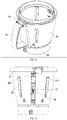
- the food preparation device includes a body 1, a container assembly 2 and a steamer assembly 3.
- the body 1 serves as a carrier of the container assembly 2 and the steamer assembly 3, and accommodates functional components such as a power system and a control system inside.
- the container assembly 2 can be mounted on the body 1, and a cutting tool assembly and a heating component are provided in the container assembly 2.
- the cutting tool assembly is configured to further process food materials, and the heating component is configured to heat the container assembly 2.
- the steamer assembly 3 as an auxiliary device is optional.
- the steamer assembly 3 can be detachably connected to the container assembly 2. When the steamer assembly 3 is needed, water is placed in the container assembly 2 and is heated by the heating component inside the container assembly 2, so that steam generated enters the steamer assembly 3.
- the container assembly 2 and the body 1 can be automatically locked together to prevent the two from being separated from each other.
- the container assembly 2 and the body 1 are unlocked by toggling the toggle member 13, and then the container assembly 2 may be removed.
- the container assembly 2 includes a cover 21 and a main body, and the main body includes a container 22, a handle 23, and a base 24.
- the cover 21 can cover the top of the container 22, and the handle 23 is provided on a side of the container 22, so that the user can hold the handle 23 by hand to move the container assembly 2 conveniently.
- a measuring cup 25 is further provided on the cover 21 and can be detachably connected to the cover 21.
- the measuring cup 25 When the measuring cup 25 is fixed to the cover 21, the measuring cup 25 can serve as a handle of the cover 21 to facilitate the user to lift or cover the cover 21. After the measuring cup 25 is detached from the cover 21, the user may use the measuring cup 25 to measure an appropriate amount of food conveniently.
- the container 22 is provided on the base 24, and the base 24 is provided with a structure that is matched with the body 1 so that the functional components in the body 1 can process the food in the container 22.
- the body 1 includes an upper casing 11 and a lower casing 12. After the upper casing 11 and the lower casing 12 are fixed, an installation chamber for accommodating the power system and the control system is formed inside the body 1.
- a tray 14 is provided on the upper casing 11, and the tray 14 is provided with a mounting groove configured to carry the container assembly 2. When the container assembly 2 is placed on the body 1, a lower end of the container assembly 2 can be inserted into the tray 14, which is beneficial to improving the fixation of the container assembly 2.
- a limiting portion 241 is provided on the container assembly 2, and a locking member 4 is movably connected to the body 1 (see FIG. 13 ).
- the locking member 4 can be driven to move relative to the body 1 to be matched with the limiting portion 241, Therefore, the container assembly 2 is prevented from being separated from the body 1, thereby achieving the purpose of locking the container assembly 2 with the body 1.
- the limiting portion 241 is provided on a side wall of the base 24 and protruded therefrom, and the locking member 4 is movably connected with the tray 14.
- the base 24 enters the tray 14 so as to be matched with the locking member 4.
- the container assembly 2 can be mounted vertically into the tray 14, and the locking member 4 can be driven to move to the top of the limiting portion 241 to prevent the container assembly 2 from being pulled out of the tray 14, thereby realizing the locking of the container assembly 2 with the body1.
- the locking realized by moving the locking member 4 to a front side of the pulling-out direction of the limiting portion 241 makes the structure of the food preparation device simple and the locking effect reliable.
- the locking member 4 is arranged to abut against the top of the limiting portion 241 to further restrict the position of the container assembly 2.
- the container assembly 2 can also be mounted into the tray 14 in other directions.
- an opening is provided on a side of the tray 14.
- the container assembly 2 may be horizontally mounted into the tray 14 through the opening, and the locking member 4 maybe moved to cross a movement track of the container assembly 2 when it is taken out.
- the locking may also be achieved by a snap connection of the limiting portion 241 with the locking member 4 or the like.
- an outer side wall of the container assembly 2 abuts against an inner side wall of the mounting groove, that is, the shape and size of the space inside the mounting groove may be the same as the shape and size of a base plate of the container assembly 2, which is beneficial to improving the limiting effect to the position of the container assembly 2.
- a groove 141 capable of accommodating the limiting portion 241 is provided on the inner sidewall of the mounting groove.
- the limiting portion 241 slides down along the groove 141 to avoid interference with the tray 14.
- the locking member 4 is driven to move to extend into the groove 141 and abut on a top surface of the limiting portion 241, so that the locking is achieved.
- a protrusion 242 is provided on the container assembly 2 and located above the limiting portion 241. After the container assembly 2 is placed on the body 1, the locking member 4 is driven to move, so that the abutting portion 41 slides into the groove 141 and is located between the protrusion 242 and the abutting portion 241, thereby further improving the locking effect between the container assembly 2 and the body 1.
- the top opening of the groove 141 may be blocked by the protrusion 242, and food residues or other sundries maybe prevented from falling into the groove 141, so that the appearance of the tray 14 is more appealing, and it is convenient for the user to quickly mount the container assembly 2 into the body 1 in a pressing-mounting direction and to lock the container assembly 2.
- the locking member 4 may rotate in the circumferential direction of the tray 14 to enter or retract out of the groove 141. With the locking member 4 rotating in the circumferential direction of the tray 14, the space required for the movement of the locking member 4 can be reduced, which is beneficial to making the structure of the food preparation device more compact and realizing a miniaturization design of the food preparation device.
- the tray 14 includes a bottom plate 142 and a side plate connected to the bottom plate 142, and the side plate and the bottom plate 142 are enclosed to form a mounting groove for accommodating the base plate of the container assembly 2.
- the side plate may be a double-layer structure formed by a process such as flanging, and the cross-sectional shape may be a U shape, so that the locking member 4 can be provided in the double-layer structure of the side plate.
- the side plate includes an inner plate 143 and an outer plate 144 formed by bending the inner plate 143 outward.
- a chamber is formed between the inner plate 143 and the outer plate 144, and a groove 141 is provided on the inner plate 143 and is in communication with the chamber.
- the locking member 4 maybe slidably arranged in the chamber.
- the above side plate structure can hide the locking member 4 and make the tray 14 more appealing as an appearance member.
- the locking member 4 slides along the circumferential direction of the chamber, making the space required for sliding small and achieving the position limiting effect to the locking member 4, which is beneficial to reducing the space required for the locking member 4 to lock the container assembly 2 with the body 1.
- the tray 14 is integrally formed, which is convenient to process and simple in structure.
- the locking member 4 may be annular, so that the locking member 4 provided in the annular chamber can have a better stability.
- an abutting portion 41 is provided on the inner side of the locking member 4. As shown in FIGS. 7 and 8 , After the container assembly 2 is mounted onto the body 1, the locking member 4 will be driven to move to cause the abutting portion 41 to slide into the groove 141, and the limiting portion 241 is located below the abutting portion 41, so that the locking between the container assembly 2 and the body 1 is realized.
- the locking member 4 will be driven to move to abut against the tops of the plurality of limiting portions 241, increasing the number of force points between the limiting portions 241 and the locking member 4, and thereby improving the locking effect to the container assembly 2.
- the number of the abutting portions 41 is the same as the number of the limiting portions 241 on the container assembly 2, which improves the locking effect to the container assembly 2.
- the protrusion 242 above one of the plurality of abutting portions 41 is provided the protrusion 242, such that a fool-proof structure maybe formed which guides the container assembly 2 is mounted on the body 1 at a specified angle, thereby improving the safety performance of the food preparation device.
- two limiting portions 241 are provided on the container assembly 2 and respectively provided on two sides of the base plate.
- Two abutting portions 41 are provided on the locking member 4, and each abutting portion 41 is engaged with one corresponding limiting portion 241 on the container assembly 2.
- the two limiting portions 241 are in directions having a 180-degree angle therebetween, so that the force applied on the container assembly 2 when being locked maybe more uniform and the locking effect may be good.
- the food preparation device includes a first locking assembly and a second locking assembly.
- the locking member 4 may be driven to move by the first locking assembly and be fixed in a locked position.
- the locked position as shown in FIG. 8
- the locking member 4 may enter the groove 141 and abut against the top of the limiting portion 241, so that the container assembly 2 is locked with the body 1.
- the locking member 4 may be driven to move by the second locking assembly and be fixed in an unlocked position. In the unlocked position, as shown in FIGS.
- the locking member 4 moves out of the groove 141 to unlock the container assembly 2 from the body 1.
- the locking member 4 is kept in a position outside the groove 141 and does not block the installation of the container assembly 2, which facilitates the user to install the container assembly 2 again.
- the first locking assembly includes a first reset member 51 and a releasing portion 52.
- the first reset member 51 is configured to drive the locking member 4 to move relative to the body 1 and move to the locked position.
- the releasing portion 52 is movably connected to the body 1, and the container assembly 2 can unlock the locking member 4 from the second locking assembly by driving the releasing portion 52 to move.
- the second locking assembly prevents the locking member 4 from resetting, that is, the locking member 4 is kept in the unlocked position, and the abutting portion 41 of the locking member 4 does not enter the groove 141, which ensures that the limiting portion 241 on the container assembly 2 maybe smoothly inserted into the groove 141, thereby realizing the container assembly 2 is placed onto the body 1.
- the limiting portion 241 on the container assembly 2 abuts against the releasing portion 52 to cause the releasing portion 52 to move relative to the body 1.
- the releasing portion 52 will unlock the locking part 4 from the second locking assembly, so that the locking part 4 will slide to the locked position relative to the body 1 under the action of the first reset member 51, and the abutting portion 41 will slide into the groove 141 and abuts the limiting portion 241 to complete the locking between the container assembly 2 and the body 1.
- the first reset member 51 may be a spring, such as a tension spring.
- One end of the tension spring may be connected to the upper casing 11 and the other end may be connected to the locking member 4, and the tension spring pulls the locking member 4 to the locked position.
- the releasing portion 52 can slide in a vertical direction relative to the body 1, which is beneficial to reducing the lateral size of the body 1, making the body 1 more compact.
- the releasing portion 52 is resettable and may automatically return to an initial position after the container assembly 2 is separated from the body 1, so that when the container assembly 2 is mounted again, the locking member 4 can be unlocked from the second locking assembly through the movement of the releasing portion 52, thereby simplifying the operation steps of the food preparation device.
- a stepped surface 1411 is provided in the groove 141.
- the abutting portion 41 slides into the groove 141, the abutting portion 41 overlaps on the stepped surface 1411, thereby improving the positioning effect between the abutting portion 41 and the groove 141.
- a plurality of supporting blocks 15 are further provided on the upper casing 11.
- the supporting blocks 15 supports the locking member 4 to maintain the locking member 4 sliding horizontally.
- the supporting surface of the supporting block 15 may be a smooth arc surface, such that the contact area between the supporting surface and the locking member 4 is reduced, thereby reducing friction.
- a supporting plate 63 is provided in the upper housing 11 and located below the tray 14.
- the releasing portion 52 is slidably connected to the supporting plate 63, and the top of the releasing portion 52 may enter the groove 141 of the tray 14 so as to be engaged with the limiting portion 241.
- the releasing portion 52 and the supporting plate 63 are connected by a second reset member 53.
- the second reset member 53 may be a spring and drives the releasing portion 52 to move upward to reset.
- a first guide rod 522 slidably penetrated through the supporting plate 63 is provided on the releasing portion 52, the second reset member 53 is sleeved on the first guide rod 522, and two ends of the second reset member 53 abut against the releasing portion 52 and the supporting plate 63 respectively.
- a second guide rod 631 may be further provided on the supporting plate 63, and a guide hole 523 is provided on the releasing portion 52.
- the second guide rod 631 may be slidably penetrated through the guide hole 523 to further restrict the sliding direction of the releasing portion 52.
- the second guide rod 631 may also be provided on the releasing portion 52, and correspondingly, the second guide rod 631 is slidably penetrated through the supporting plate 63.
- the second locking assembly includes a block 43 provided on the locking member 4.
- the locking member 4 is in the unlocked position, and the releasing portion 52 is raised under the action of the second reset member 53, causing the block 43 to abut on the abutting surface 524 on the right side of the releasing portion 52, so that the locking member 4 overcomes the force of the first reset member 51 and maintains in the unlocked position.
- the block 43 By setting the block 43 to be engaged with the releasing portion 52, when the container assembly 2 is not mounted on the body 1, the body 1 is always in an unlocked state, which facilitates the engagement of the container assembly 2 with the body 1.
- the limiting portion 241 of the container assembly 2 presses the releasing portion 52, causing the releasing portion 52 to move downward and no longer abut against the block 43.
- the locking member 4 will reset under the action of the first reset member 51 and move to the locked position, causing the abutting portion 41 to be engaged with the limiting portion 241, and thus the container assembly 2 is locked.
- the top of the releasing portion 52 is further provided with a first guide surface 525.
- the first guide surface 525 is an oblique surface that is inclined downward in a direction along which the locking member 4 moves towards the locked position.
- the first guide surface 525 can be slidably engaged with the block 43, which is beneficial to reducing the resistance of the locking member 4 when it is resetting.
- the second locking assembly further includes a toggle member 13 which is movably connected to the body 1.
- One end of the toggle member 13 is engaged with the locking member 4 and the other end extends out of the body 1 for the user to hold conveniently.
- the locking member 4 can be driven to move to the unlocked position by toggling the toggle member 13.
- the container assembly 2 has not been removed. Due to the weight of the container assembly 2 itself and the weight of the food inside the container assembly 2, the releasing portion 52 is still in a pressed state, which allows the block 43 to return to the unlocked position smoothly.
- the unlocking assembly is further provided with a resettable locking block 61 movably connected to the body 1.
- the locking block 61 can always abut against the locking member 4 until the locking member 4 moves to the unlocked position at which the locking block 61 maybe locked with the locking member 4, so that when the releasing portion 52 is in a pressed state, the locking member 4 may be held in the unlocked position by the engagement between the locking block 61 and the locking member 4.
- a protruding portion 612 is provided on a side of the locking block 61 towards the locking member 4, and a lock slot 42 is provided on the locking member 4.
- the protruding portion 612 may snap into the lock slot 42 to perform pre-unlocking of the container assembly 2 and prevent the locking member 4 from resetting, so that the locking member 4 is kept in the unlocked position.
- the locking block 61 is slidably provided on the supporting plate 63, and the sliding direction thereof is the front-rear direction shown in FIG. 14 .
- the locking block 61 is connected to the bottom of the tray 14 by a third reset member 62.
- the third reset member 62 may drive the locking block 61 to move in a direction approaching the locking member 4, so that the locking block 61 can be engaged with the locking member 4 after reset.
- the releasing portion 52 and the locking block 61 are both arranged on the inner side of the locking member 4, and the locking block 61 is driven by the third reset member 62 to move backward in the direction shown in FIG. 14 to be engaged with the locking member 4.
- the locking block 61 always abuts against the inner wall of the locking member 4 under the action of the third reset member 62.
- the third reset member 62 may be a spring, such as a pressure spring.
- the releasing portion 52 is raised under the action of the second reset member 53, so that the block 43 abuts on the abutting surface 524, and further locks the locking member 4 in the unlocked position.
- the locking block 61 Since the locking block 61 is arranged to be engaged with the locking member 4, when the container assembly 2 is not mounted, the locking member 4 is locked in the unlocked position under a common action of the abutment between the block 43 and the abutting surface 524 and the engagement between the protruding portion 612 and the lock slot 42.
- the container assembly 2 is mounted, through pressing the releasing portion 52 down by the limiting portion 241, only the abutting surface 524 of the releasing portion 52 is no longer in contact with the block 43, but the protruding portion 612 and the lock groove 42 are still in an engagement state. Therefore, the locking member 4 cannot be moved to the locked position under the action of the first reset member 51.
- the releasing portion 52 may also drive the locking block 61to move forward in the direction shown in FIG. 15 , so that the protruding portion 612 slides out of the lock groove 42, and thus the locking member 4 is unlocked from the locking block 61.
- a second guide surface 521 is further provided on the side of the releasing portion 52 close to the locking block 61, and the locking block 61 is provided with a guide portion 611 capable of being slidably engaged with the second guide surface 521.
- the second guide surface 521 is an oblique surface which is inclined gradually downward in a direction away from the locking member 4, that is, from back to front.
- the guide portion 611 on the locking block 61 always abuts on the second guide surface 521 under the action of the third reset member 62, and the guide portion 611 slides downward along the second guide surface 521 relative to the releasing portion 52, causing the locking block 61 as a whole to slide in the forward direction shown in FIG. 15 , and the protruding portion 612 on the locking block 61 gradually slides out of the lock slot 42 on the locking member 4.
- the protruding portion 612 is completely separated from the lock slot 42 and the releasing portion 52 abuts against the block 43 to achieve the locking to the locking member 4, so that the locking member 4 is still kept in the unlocked position.
- the releasing portion 52 moves downward, and the block 43 slides along the first guide surface 525, so that the locking member 4 is gradually reset to the locked position under the action of the first reset member 51.
- the guide portion 611 will move upward along the second guide surface 521 to cause the locking block 61 to move backward as a whole. Since the locking member 4 has been resetting, the lock slot 42 has been deviated from the protruding portion 612 of the locking block 61, which prevents the protruding portion 612 from being engaged with the lock slot 42, and thus the locking member 4 may move to the locked position smoothly.
- a food preparation device which is different from the food preparation device of the first embodiment in that, regarding to the food preparation device, whether the container assembly 2 is locked with the body 1 or not may be determined, and the food preparation device can be started only after the container assembly 2 is locked with the body, which ensures that the user can only start the food preparation device under the condition that the container assembly 2 is locked with the body 1.
- the food preparation device further includes a trigger mechanism which may determine whether the container assembly 2 is locked with the body 1 or not.
- a trigger mechanism which may determine whether the container assembly 2 is locked with the body 1 or not.
- the locking member 4 is moved to the locked position to lock the container assembly 2.
- the trigger mechanism may be triggered by the locking member 4 in the locked position so as to obtain information that the container assembly 2 and the body 1 are already in a locked state.
- the trigger mechanism includes a first sensing member 75 and a first bracket 76.
- the first bracket 76 is provided under the tray 14, and the first sensing member 75 is provided on the first bracket 76.
- the first sensing member 75 may be a micro switch.
- the micro switch When the locking member 4 moves to the locked position, the locking member 4 can abut against the reed of the micro switch to trigger the micro switch, the micro switch therefore acquires the information that the container assembly 2 and the body 1 are in the locked state, and the food preparation device may start to work normally according to the information.
- control system of the food preparation device may be electrically connected to the trigger mechanism.
- the micro switch obtains state information that the container assembly 2 and the body 1 are in the locked state, and transmits the state information to the control system.
- the control system acquires the locked state of the container assembly 2to the body 1 according to the received the information, and will control the food preparation device to work normally according to the user's input information.
- control system may include a control button.
- control system will determine whether the state information sent by the micro switch is received. If the information is received, the control system controls the food preparation device to execute work instructions. If the information is not received, the control system alarms to remind the user that the container assembly 2 is not locked with the body 1.
- the first sensing member 75 may be configured as contact sensor or proximity sensor which may implement the corresponding functions.
- the cover 21 may be also detected whether the cover 21 is normally closed on the container 22, so that the cover 21 or food in the container 22 may be avoided being thrown out due to the loosening of the cover 21 during the operation of the food preparation device, thereby improving the safety performance of the food preparation device.
- a triggering member 26 is provided on the container assembly 2.
- the triggering member 26 can trigger the trigger mechanism in the body 1, otherwise, the triggering member 26 cannot trigger the trigger mechanism, such that whether the cover 21 and the container 22 are normally closed or not can be determined.
- a triggering member 26 is provided on the container assembly 2, and can be provided in the handle 23.
- the triggering member 26 extends out of the handle 23 for a relatively longer length to trigger the trigger mechanism on the body 1, so that information that the cover 21 has already been normally mounted on the container 22 may be generated.
- the triggering member 26 extends out of the handle 23 for a relatively shorter length, and thus the triggering member 26 cannot trigger the trigger mechanism on the body 1, thereby determining that the cover 21 is not normally closed onto the container 22.
- the trigger mechanism further includes a second sensing member 72.
- the second sensing member 72 may be a micro switch.
- the cover 21 is normally closed onto the container 22 and the container assembly 2 is mounted on the body 1, the triggering member 26 can abut on the reed of the second sensing member 72, such that the second sensing member 72 acquires a state signal indicating the container assembly 2 is mounted.
- the trigger mechanism may further include a resettable adapter 71slidably provided in the chamber of the tray 14, as shown in FIG. 17 , FIG. 20 and FIG. 21 .
- One end of the adapter 71 penetrates through the tray 14 and can abut against the trigger 26, and the other end can be driven by the triggering member 26 to abut against the reed of the second sensing member 72 so as to trigger the trigger mechanism.
- the triggering member 26 presses down the adapter 71, and thus the adapter 71 can abut against the reed of the second sensing member 72, such that the second sensing member 72 acquires the state signal indicating the container assembly 2 is mounted.
- the adapter 71 When the triggering member 26 no longer abuts against the adapter 71, the adapter 71 is automatically reset and separated from the reed of the second sensing member 72, causing the second sensing member 72 not to be triggered and indicating that the cover 21 is not normally closed onto the container 22.
- the second sensing member 72 and the adapter 71 can be provided in a chamber of the tray 14, and the space between the inner plate 143 and the outer plate 144 in the tray 14 is reasonably utilized, so that the structure of the food preparation device is more compact.
- the trigger mechanism further includes a second bracket 74, and both the adapter 71 and the second sensing member 72 can be provided on the second bracket 74.
- a fourth reset member 73 is provided between the adapter 71 and the second bracket 74. The fourth reset member 73 abuts on the second bracket 74 and the adapter 71 by its two ends respectively to drive the adapter 71 to extend out of the tray 14, so that the adapter 71 may be engaged with the triggering member 26.
- the fourth reset member 73 may be a spring.
- a contact end is further provided on the adapter 71. During the upward and downward sliding of the adapter 71, the adapter 71 can drive the contact end to abut against or separate from the reed of the second sensing member 72.
- a notch 231 is provided on the handle 23 .
- a first inclined surface 211 is provided on the cover 21
- the triggering member 26 is resetably provided on the container 22 and is provided with a second inclined surface 261
- the cover 21 is closed onto the container 22 in a rotating manner.
- the triggering member 26 may be retracted into the handle 23 under the action of the fifth reset member 27.
- the first inclined surface 211 on the cover 21 can be slidably engaged with the second inclined surface 261 on the triggering member 26, and push the triggering member 26 to slide downwards, such that the bottom end of the triggering member 26 gradually extends out of the handle 23 so as to abut against the adapter 71.
- the food preparation device executes the work instruction. That is, only after the locking member 4 triggers the first sensing member 71, and the triggering member 26 triggers the second sensing member 72, the food preparation device executes the work instruction, which further improves the safety performance of the food preparation device.
- the food preparation device of the embodiment 3 further includes a detection assembly.
- the detection assembly may detect the mounting state of the cutting tool assembly 8 onto the container assembly 2, so as to prevent the food preparation device from starting when the cutting tool assembly 8 is in an abnormal mounting state.
- the detection assembly includes a sensing element and a to-be-sensed element.
- the sensing element can be provided in the tray 14 of the body 1, and the to-be-sensed element can be provided on a transmission end of the cutting tool assembly 8.
- the transmission end is normally matched with the driving assembly, the to-be-sensed element is located within the detection range of the sensing element.
- the to-be-sensed element may be a magnetic member
- the sensing element may be a Hall sensor or a dry-reed switch, so that the detection assembly maybe magnetic detection type.
- the dry-reed switch also called as a reed switch or a magnetic reed switch, is a magnetically sensitive switch and usually includes two metal reed contacts which are made of a soft magnetic material and disconnected when there is no magnetism.
- the dry-reed switch when the magnetic member moves into the sensing range of the dry-reed switch, the two contacts in the dry-reed switch are in contact, and the dry-reed switch is switched on, so that it can be detected that the cutting tool assembly 8 has been mounted in position. Otherwise, the cutting tool assembly 8 is not mounted normally, and the magnetic member is located outside the sensing range of the dry-reed switch, in this case, the two contacts of the reed switch are not in contact, and thus the dry-reed switch is switched off.
- the detection assembly may be configured as a contact sensor or a proximity sensor.
- the receiving end of the sensor may serve as the sensing element, and the transmission end of the sensor may serve as the to-be-sensed element, so that the sensor may be also used to detect whether the cutting tool assembly 8 is mounted in position or not.
- the transmission end of the cutting tool assembly 8 extends out of the container assembly 2.
- the driving assembly includes a transmission seat 91 extending into the tray 14. The cutting tool assembly 8 extending out of the container assembly 2 is connected to the transmission seat 91 by the transmission end thereof to be driven to rotate.
- the cutting tool assembly 8 includes a cutting tool 81 and a cutting tool seat 83.
- the cutting tool seat 83 is detachably mounted at the bottom of the container assembly 2.
- the cutting tool 81 includes a rotating shaft and a blade.
- the rotating shaft of the cutting tool 81 is rotatably arranged in the cutting tool seat 83, with the bottom end thereof extending out of the cutting tool seat 83 and connected to a transmission end.
- the transmission end may be provided with a spline 84.
- the blade and the spline 84 are respectively located on two sides of a mounting seat.
- a locking element 82 of the cutting tool is further fixedly connected onto the cutting tool seat 83 and is detachably fixed on the cutting tool 81.
- the cutting tool assembly 8 When the cutting tool assembly 8 is mounted, the cutting tool assembly 8 is mounted from the inner side of the container 22, a limiting portion 241 provided on the upper end of the cutting tool seat 83 abuts against the inner side of the container 22, and the lower end of the cutting tool seat 83 and the transmission end extend out of the container assembly 2. Then the locking element 82 of the cutting tool is fixed onto the cutting tool seat 83 and is engaged with the limiting portion 241 to fix the cutting tool assembly 8 onto the container assembly 2.
- the locking element 82 of the cutting tool is fixed onto the cutting tool seat 83 in a screwing manner, for example, the locking element 82 of the cutting tool is fixed to the cutting tool seat 83 by a threaded connection.
- the magnetic member may be provided on the lock cutting tool element 82.
Applications Claiming Priority (2)
| Application Number | Priority Date | Filing Date | Title |
|---|---|---|---|
| CN201910785405.3A CN110313854B (zh) | 2019-08-23 | 2019-08-23 | 一种料理机 |
| PCT/CN2019/114115 WO2021035930A1 (fr) | 2019-08-23 | 2019-10-29 | Robot de cuisine |
Publications (3)
| Publication Number | Publication Date |
|---|---|
| EP3821774A1 true EP3821774A1 (fr) | 2021-05-19 |
| EP3821774A4 EP3821774A4 (fr) | 2021-12-08 |
| EP3821774B1 EP3821774B1 (fr) | 2024-05-08 |
Family
ID=68126377
Family Applications (1)
| Application Number | Title | Priority Date | Filing Date |
|---|---|---|---|
| EP19940954.1A Active EP3821774B1 (fr) | 2019-08-23 | 2019-10-29 | Robot de cuisine |
Country Status (3)
| Country | Link |
|---|---|
| EP (1) | EP3821774B1 (fr) |
| CN (1) | CN110313854B (fr) |
| WO (1) | WO2021035930A1 (fr) |
Families Citing this family (8)
| Publication number | Priority date | Publication date | Assignee | Title |
|---|---|---|---|---|
| CN110313854B (zh) * | 2019-08-23 | 2021-10-26 | 莱克电气股份有限公司 | 一种料理机 |
| CN111407168B (zh) * | 2020-04-02 | 2023-04-11 | 浙江百力科技有限公司 | 一种豆浆机 |
| WO2021238412A1 (fr) * | 2020-05-29 | 2021-12-02 | 纯米科技(上海)股份有限公司 | Appareil de cuisson du type à agitation |
| DE102020209668A1 (de) * | 2020-07-30 | 2022-02-03 | BSH Hausgeräte GmbH | Vertikaler Verriegelungsmechanismus auf einem Haushaltsgerät |
| CN114668320B (zh) * | 2020-12-24 | 2024-03-12 | 莱克电气绿能科技(苏州)有限公司 | 一种料理机 |
| CN114680672B (zh) * | 2020-12-25 | 2023-12-22 | 莱克电气绿能科技(苏州)有限公司 | 料理组件及料理设备 |
| CN114869149A (zh) * | 2021-02-05 | 2022-08-09 | 莱克电气绿能科技(苏州)有限公司 | 锁刀结构以及料理机 |
| CN114305168B (zh) * | 2021-12-02 | 2023-12-12 | 广东纯米电器科技有限公司 | 食物料理机 |
Family Cites Families (17)
| Publication number | Priority date | Publication date | Assignee | Title |
|---|---|---|---|---|
| US5908242A (en) * | 1998-11-06 | 1999-06-01 | Hp Intellectual Corp. | Stand mixer with locking connection between the mixing bowl and the bowl support |
| US6817750B1 (en) * | 2003-08-26 | 2004-11-16 | Homeland Housewares, Llc | Individualized blender |
| FR2932077A1 (fr) * | 2008-06-06 | 2009-12-11 | Seb Sa | Recipient de travail comportant une platine porte-outil amovible et appareil electromenager de preparation culinaire muni d'un tel recipient |
| US10449685B2 (en) * | 2010-04-29 | 2019-10-22 | Whirlpool Corporation | Food processor with adjustable blade assembly |
| FR3019024B1 (fr) * | 2014-03-25 | 2017-02-17 | Seb Sa | Appareil electromenager de preparation culinaire comprenant un recipient ferme par un couvercle amovible cooperant avec un dispositif de securite |
| CN204765232U (zh) * | 2015-03-09 | 2015-11-18 | 广东顺德迪泰隆电器有限公司 | 一种锁定装置及食品料理机 |
| CN205107447U (zh) * | 2015-11-10 | 2016-03-30 | 浙江绍兴苏泊尔生活电器有限公司 | 料理机 |
| CN205306815U (zh) * | 2016-01-20 | 2016-06-15 | 宁波凯普电子有限公司 | 带微动安全启动的料理机 |
| CN205866652U (zh) * | 2016-04-15 | 2017-01-11 | 广州市福立达电器有限公司 | 食物料理机 |
| CN106691149B (zh) * | 2017-03-03 | 2018-11-27 | 广东百晟图电器实业有限公司 | 果汁机 |
| CN107095599B (zh) * | 2017-06-15 | 2023-09-22 | 广东百胜图科技有限公司 | 一种带安全锁的食物处理组件 |
| CN208510861U (zh) * | 2017-08-07 | 2019-02-19 | 浙江绍兴苏泊尔生活电器有限公司 | 料理杯组件及料理机 |
| CN208926012U (zh) * | 2018-05-07 | 2019-06-04 | 浙江绍兴苏泊尔生活电器有限公司 | 一种料理机 |
| CN108567304B (zh) * | 2018-06-15 | 2023-07-21 | 莱克电气股份有限公司 | 一种食品处理装置 |
| CN108567303B (zh) * | 2018-06-15 | 2023-06-23 | 莱克电气股份有限公司 | 一种食品处理装置 |
| CN109464039A (zh) * | 2018-11-29 | 2019-03-15 | 黄文雄 | 食物破壁料理机 |
| CN110313854B (zh) * | 2019-08-23 | 2021-10-26 | 莱克电气股份有限公司 | 一种料理机 |
-
2019
- 2019-08-23 CN CN201910785405.3A patent/CN110313854B/zh active Active
- 2019-10-29 WO PCT/CN2019/114115 patent/WO2021035930A1/fr unknown
- 2019-10-29 EP EP19940954.1A patent/EP3821774B1/fr active Active
Also Published As
| Publication number | Publication date |
|---|---|
| CN110313854A (zh) | 2019-10-11 |
| EP3821774A4 (fr) | 2021-12-08 |
| CN110313854B (zh) | 2021-10-26 |
| EP3821774B1 (fr) | 2024-05-08 |
| WO2021035930A1 (fr) | 2021-03-04 |
Similar Documents
| Publication | Publication Date | Title |
|---|---|---|
| EP3821774B1 (fr) | Robot de cuisine | |
| EP3821773A1 (fr) | Robot de cuisine | |
| US4396159A (en) | Protective guide structure for preventing inadvertent actuation of a food processor with a tilted cover | |
| US6776086B1 (en) | Safety switch for a food processor | |
| PL346942A1 (en) | Safety system to prevent the functioning of a blender or food processor if the top of its cup is not in place | |
| US10939783B2 (en) | Food processor lid | |
| US20120175444A1 (en) | Method for operating a food processor | |
| CN211985141U (zh) | 一种安全性好的食品加工机 | |
| US6726353B1 (en) | Electric hand operated rotary beater/mixer comprising a safety device | |
| US4520703A (en) | Electromotively driven household slicing machine for food | |
| JP4015967B2 (ja) | 食材調製器 | |
| CN210748879U (zh) | 一种料理机 | |
| CN210493822U (zh) | 多功能食物处理装置 | |
| WO2005011454B1 (fr) | Appareil electromenager de preparation culinaire comportant un dispositif de verrouillage et un dispositif de securite sans indexage du couvercle | |
| JP5522837B2 (ja) | 電動調理器 | |
| CN219374453U (zh) | 食品加工机 | |
| CN216256703U (zh) | 原料容器固定结构及咖啡机 | |
| CN219877988U (zh) | 一种少油的用于煎烤的烹饪设备 | |
| CN217039821U (zh) | 搅拌杯组件及料理机 | |
| CN219249932U (zh) | 多功能料理设备 | |
| CN210043858U (zh) | 杯体组件和料理机 | |
| CN117356945A (zh) | 一种具有榨汁功能的多功能食物处理机 | |
| CN208822548U (zh) | 杯体组件及料理机 | |
| KR20170140724A (ko) | 다용도 음식제조기용 오븐 안전 잠금장치 | |
| JPS6115537B2 (fr) |
Legal Events
| Date | Code | Title | Description |
|---|---|---|---|
| STAA | Information on the status of an ep patent application or granted ep patent |
Free format text: STATUS: UNKNOWN |
|
| STAA | Information on the status of an ep patent application or granted ep patent |
Free format text: STATUS: THE INTERNATIONAL PUBLICATION HAS BEEN MADE |
|
| PUAI | Public reference made under article 153(3) epc to a published international application that has entered the european phase |
Free format text: ORIGINAL CODE: 0009012 |
|
| STAA | Information on the status of an ep patent application or granted ep patent |
Free format text: STATUS: REQUEST FOR EXAMINATION WAS MADE |
|
| 17P | Request for examination filed |
Effective date: 20210215 |
|
| AK | Designated contracting states |
Kind code of ref document: A1 Designated state(s): AL AT BE BG CH CY CZ DE DK EE ES FI FR GB GR HR HU IE IS IT LI LT LU LV MC MK MT NL NO PL PT RO RS SE SI SK SM TR |
|
| A4 | Supplementary search report drawn up and despatched |
Effective date: 20211108 |
|
| RIC1 | Information provided on ipc code assigned before grant |
Ipc: A47J 43/046 20060101ALI20211102BHEP Ipc: A47J 43/07 20060101AFI20211102BHEP |
|
| DAV | Request for validation of the european patent (deleted) | ||
| DAX | Request for extension of the european patent (deleted) | ||
| GRAP | Despatch of communication of intention to grant a patent |
Free format text: ORIGINAL CODE: EPIDOSNIGR1 |
|
| STAA | Information on the status of an ep patent application or granted ep patent |
Free format text: STATUS: GRANT OF PATENT IS INTENDED |
|
| INTG | Intention to grant announced |
Effective date: 20231214 |
|
| GRAS | Grant fee paid |
Free format text: ORIGINAL CODE: EPIDOSNIGR3 |
|
| GRAA | (expected) grant |
Free format text: ORIGINAL CODE: 0009210 |
|
| STAA | Information on the status of an ep patent application or granted ep patent |
Free format text: STATUS: THE PATENT HAS BEEN GRANTED |
|
| AK | Designated contracting states |
Kind code of ref document: B1 Designated state(s): AL AT BE BG CH CY CZ DE DK EE ES FI FR GB GR HR HU IE IS IT LI LT LU LV MC MK MT NL NO PL PT RO RS SE SI SK SM TR |
|
| REG | Reference to a national code |
Ref country code: GB Ref legal event code: FG4D |