EP3821307B1 - Fräsverfahren - Google Patents
Fräsverfahren Download PDFInfo
- Publication number
- EP3821307B1 EP3821307B1 EP19736669.3A EP19736669A EP3821307B1 EP 3821307 B1 EP3821307 B1 EP 3821307B1 EP 19736669 A EP19736669 A EP 19736669A EP 3821307 B1 EP3821307 B1 EP 3821307B1
- Authority
- EP
- European Patent Office
- Prior art keywords
- spindle
- path
- speed
- phase position
- workpiece
- Prior art date
- Legal status (The legal status is an assumption and is not a legal conclusion. Google has not performed a legal analysis and makes no representation as to the accuracy of the status listed.)
- Active
Links
Images



Classifications
-
- B—PERFORMING OPERATIONS; TRANSPORTING
- B23—MACHINE TOOLS; METAL-WORKING NOT OTHERWISE PROVIDED FOR
- B23C—MILLING
- B23C3/00—Milling particular work; Special milling operations; Machines therefor
-
- G—PHYSICS
- G05—CONTROLLING; REGULATING
- G05B—CONTROL OR REGULATING SYSTEMS IN GENERAL; FUNCTIONAL ELEMENTS OF SUCH SYSTEMS; MONITORING OR TESTING ARRANGEMENTS FOR SUCH SYSTEMS OR ELEMENTS
- G05B19/00—Program-control systems
- G05B19/02—Program-control systems electric
- G05B19/18—Numerical control [NC], i.e. automatically operating machines, in particular machine tools, e.g. in a manufacturing environment, so as to execute positioning, movement or co-ordinated operations by means of program data in numerical form
- G05B19/4093—Numerical control [NC], i.e. automatically operating machines, in particular machine tools, e.g. in a manufacturing environment, so as to execute positioning, movement or co-ordinated operations by means of program data in numerical form characterised by part programming, e.g. entry of geometrical information as taken from a technical drawing, combining this with machining and material information to obtain control information, named part program, for the NC machine
- G05B19/40937—Numerical control [NC], i.e. automatically operating machines, in particular machine tools, e.g. in a manufacturing environment, so as to execute positioning, movement or co-ordinated operations by means of program data in numerical form characterised by part programming, e.g. entry of geometrical information as taken from a technical drawing, combining this with machining and material information to obtain control information, named part program, for the NC machine concerning programming of machining or material parameters, pocket machining
-
- G—PHYSICS
- G05—CONTROLLING; REGULATING
- G05B—CONTROL OR REGULATING SYSTEMS IN GENERAL; FUNCTIONAL ELEMENTS OF SUCH SYSTEMS; MONITORING OR TESTING ARRANGEMENTS FOR SUCH SYSTEMS OR ELEMENTS
- G05B2219/00—Program-control systems
- G05B2219/30—Nc systems
- G05B2219/34—Director, elements to supervisory
- G05B2219/34175—Overlap, between two blocks, continuous, smooth speed change, movement
-
- G—PHYSICS
- G05—CONTROLLING; REGULATING
- G05B—CONTROL OR REGULATING SYSTEMS IN GENERAL; FUNCTIONAL ELEMENTS OF SUCH SYSTEMS; MONITORING OR TESTING ARRANGEMENTS FOR SUCH SYSTEMS OR ELEMENTS
- G05B2219/00—Program-control systems
- G05B2219/30—Nc systems
- G05B2219/49—Nc machine tool, till multiple
- G05B2219/49077—Control of feed and spindle, cutting speed
-
- Y—GENERAL TAGGING OF NEW TECHNOLOGICAL DEVELOPMENTS; GENERAL TAGGING OF CROSS-SECTIONAL TECHNOLOGIES SPANNING OVER SEVERAL SECTIONS OF THE IPC; TECHNICAL SUBJECTS COVERED BY FORMER USPC CROSS-REFERENCE ART COLLECTIONS [XRACs] AND DIGESTS
- Y02—TECHNOLOGIES OR APPLICATIONS FOR MITIGATION OR ADAPTATION AGAINST CLIMATE CHANGE
- Y02P—CLIMATE CHANGE MITIGATION TECHNOLOGIES IN THE PRODUCTION OR PROCESSING OF GOODS
- Y02P90/00—Enabling technologies with a potential contribution to greenhouse gas [GHG] emissions mitigation
- Y02P90/02—Total factory control, e.g. smart factories, flexible manufacturing systems [FMS] or integrated manufacturing systems [IMS]
Definitions
- the invention relates to a method for machining a workpiece with a milling tool that is arranged on a rotatable spindle, the spindle being displaced relative to the workpiece or the workpiece relative to the spindle along a machining path, and the spindle rotating about a spindle axis, with a speed and/or a phase position of the rotation of the spindle along the machining path is controlled, as well as a device and a computer program for carrying out the method and a data structure for coding the computer program.
- Numerical controls are used in modern machine tools to control the positioning and movement of tools relative to a workpiece. In order to machine a workpiece according to a specification, it is necessary to move the tool relative to the workpiece along predetermined paths.
- a path control The desired paths are defined in a parts program that is processed by the numerical control.
- the numerical control converts the geometric instructions of the parts program into instructions for the position control of the various feed axes of the machine tool.
- the milling spindle that drives the tool is usually operated at a technologically determined, constant speed that is specified in the part program. (S word according to DIN 66025).
- a path speed is also programmed in the part program for the tool (F word according to DIN 66025), which usually refers to the TCP (tool center point) or to the position of the tool engagement on the tool.
- Generic milling methods are, for example, from DE 10 2015 112 577 A1 , the DE 10 2010 060 220 A1 , the WO 2017/056025 A1 , the "Milling with SINUMERIK - mold making from 3 to 5 axes simultaneous milling" or the JP 2017-001153 A1 known.
- the spindle position is not exactly linked to the path feed (e.g. with a speed-controlled spindle) or the path length integral in neighboring milling paths is not a multiple of the tooth feed (offset even with the given position coupling between feed axes and spindle).
- milled workpieces manufactured according to the state of the art typically show irregular linear surface structures as in figure 8 shown on.
- the milling paths run from left to right. It can be seen how the engagement points of the tool cutting edges in adjacent milling paths are randomly synchronous. Again and again, however, shifts occur, which then lead to an optically uneven appearance (wider stripes) of the surface. In the case of tools for injection molding or the like, this structure can be transferred to the end product.
- One object of the invention is to specify a method that makes it possible to specifically produce a phase position of the tool cutting edge interventions in adjacent milling paths. This should bring about an improvement in the surface quality in particular.
- the above problem is solved in particular by a method for machining a workpiece with a milling tool that is arranged on a rotatable spindle, the spindle being displaced relative to the workpiece or the workpiece relative to the spindle along a machining path and the spindle being displaced about a spindle axis rotates, wherein a speed and / or a phase position of the rotation of the spindle is controlled along the machining path and wherein the Machining path includes line-shaped parallel tracks.
- the machining path comprises parallel paths arranged next to one another in rows, and the phase position of the spindle is the same or essentially the same along the machining path in adjacent paths. Due to the same phasing, the pattern brought into the surface by the milling process is the same in neighboring strips, giving the optical impression of an evenly processed surface. The surface quality therefore makes it possible to dispense with polishing the surface.
- the phasing is controlled by varying the speed of the spindle and/or the feed rate of the spindle relative to the workpiece along the machining path.
- the rotational speed and/or the phase position is/are controlled to a predetermined desired value at at least one synchronization point along the machining path.
- the rotational speed and/or the phase position is/are controlled along the machining path at a plurality of synchronization points to a respective predetermined desired value.
- the control of the rotational speed and phase angle to the desired value is started at a trigger point.
- the phase position is controlled by reducing or increasing the spindle speed.
- the phase position of the spindle can be controlled simply by controlling the spindle speed.
- the phasing is controlled by decreasing or increasing the feed rate of the spindle relative to the workpiece along the machining path.
- intervention in the advance is used to synchronize the phase position.
- the phasing of a milling tool with multiple cutting edges is shifted by a multiple of the pitch of the cutting edges.
- individual cutting edges are used synchronized. For example, if the milling head has 10 cutting edges, synchronization can take place every 36° (360°/10).
- a device for carrying out a method according to one of the preceding claims comprises means for displacing a workpiece relative to a milling tool arranged on a spindle and means for speed control and phase control of the rotation of the spindle.
- the spindle is driven by a position-controlled electric motor.
- the device comprises means for determining the angular position of the spindle.
- the problem mentioned at the outset is also solved by a computer program for executing a method according to the invention and a data structure for coding a computer program for executing a method according to the invention.
- NC programs describe the milling path in a sequence of simple geometry elements.
- (Orbit) support points or path support points are the respective borders between two following geometry elements. These coordinates are taken from the NC program per line as an NC block.
- the path parameter also referred to as the path length integral
- the path parameter describes exactly one point on the path described in the part program, which can certainly lie between the interpolation points of the NC blocks
- a trigger point is the start (in time and/or path parameters) for planning a movement profile towards a synchronous point.
- a technologically conditioned tooth feed is defined.
- the task of every CNC is, in principle, to adhere to this programmed (desired or maximum) feed rate as precisely as possible, while adhering to the dynamic limit values of the axes involved, without exceeding this maximum value.
- the feed level In areas where the path is curved, the feed level must be lowered in order not to dynamically overstrain the axis feed drives or to meet certain requirements for path accuracy. is realized This is done by pre-calculating a so-called speed limit value profile as part of the so-called path planning, as described in figure 1 is shown.
- Every program line is in figure 1 as well as in the following text based on Din/Iso or G-Code with N10, N20 and so on up to N100.
- a state-of-the-art CNC controller determines a maximum speed of the feed as a speed limit value profile for path planning.
- the speed limit value profile contains the feed programmed in the NC program or the feed speed v lim, prog and, as a result of the path analysis, the dynamically determined maximum values for the path speed within the block v lim, dyn and the maximum transition speed per block transition v lim, via .
- the task of the downstream, so-called speed profile generator is to calculate a speed profile over the path parameter (or the time, depending on the implementation), which is based on the minimum values of the limit value profile from below, i.e. from lower values, since the maximum value must not be exceeded , through constant tangent speed curves at the highest possible level, but at no point exceeds the limit value profile. If a representation over time is selected, then the speed profile results in polynomial segments of the 2nd order, the segment boundaries of which in the most general case are neither exactly on a block boundary nor on a point in time that is later scanned by the interpolator, as is shown in figure 2 is shown.
- the speed v B is at every point below the in figure 1 shown values of v lim, prog , v lim,dyn and v lim, via .
- the speed profile calculated in this way is scanned as IPO scanning points by the so-called scanning interpolator in the cycle time of the so-called interpolation cycle and the position setpoints for all feed axes involved in the movement are calculated.
- This also means that not every NC support point is output to the axis controller exactly as a position setpoint, because the exact NC block limit is usually between two IPO scanning points.
- the scanning is shown schematically in figure 3 shown. With a time interval T a , position values s b are determined by corresponding displacement sensors of all axes and forwarded to the controller.
- the speed profile of a position-controlled spindle is determined and controlled via the path profile.
- the angle (phase) of the spindle is controlled to a specified value at certain points.
- a graphical representation is based on that of the web speed profile.
- the speed of a position-controlled spindle can be measured as a path speed profile in the same representation of a speed plan over the path parameter (or time) as in figure 4 shown.
- the cyclic position setpoints can then be sampled simultaneously by both profiles.
- each interpolated path point is assigned exactly one spindle orientation (i.e. an angle of the spindle relative to a zero point; a phase of the rotation of the spindle).
- spindle orientation i.e. an angle of the spindle relative to a zero point; a phase of the rotation of the spindle.
- An exact spindle orientation is assigned to at least one point on the path to supply the target parameters. According to the invention, this assignment takes place particularly advantageously in the NC program.
- the programming of such a synchronization condition leads to at least ( figure 5 ) once per adjacent milling path to a specified spindle orientation.
- the object of the method according to the invention is first of all to determine whether trajectory planning is possible while maintaining the dynamic limit values. In the event that trajectory planning is possible, two possible methods for establishing synchronicity are described below. In addition, a method is specified as to how advantageously the case can be dealt with when trajectory planning is not possible.
- the syntax extension provides a command G119 that expects a parameter S specifying an angular position of the spindle relative to a zero point (phase position).
- each setpoint position can be reached in two ways (rotating forwards or backwards). If the information about the direction of rotation is known, the position specification works up to 360° / TA . In other words, with an interpolation cycle of 1ms up to 60,000 rpm spindle speed.
- trajectory planning is possible, two methods can be used.
- the spindle performs a phase adjustment.
- the individual program lines are labeled N10, N20 and so on.
- the program line N70 contains the information that the spindle should assume an angle of 77° there.
- the created area in figure 5 is the velocity-time integral that corresponds to the required phase correction of the spindle position.
- the respective segment boundaries of the speed profiles are circled.
- the process is time-optimal without influencing the feed planning and has absolutely no negative influence on the total processing time of the part program.
- the position setpoint output to the spindle in the last cycle is known, as is the exact path parameter and thus also the duration (in path and time) until the synchronization point is reached.
- the angular position of the spindle at the synchronization point can be calculated if the spindle speed is not corrected.
- the amount of phase compensation required is then the difference between these two angular positions in the modulo circle. In the case of multi-edged tools, the required phase compensation can of course also be reduced to angular positions of 360°/number of cutting edges.
- a spindle speed profile can then be calculated that establishes the synchronization point exactly at the block limit. If the path feed (as in our example) is not constant during the phase correction of the spindle, it is important that the The spindle synchronization process ends exactly at the block boundary.
- the phase compensation takes place by lowering the feed level for a limited period of time, see FIG figure 6 .
- the procedure for temporarily lowering the feed level of the velocity profile is particularly efficient for high-speed spindles.
- the required amount and duration of the feed reduction are low because the spindle assumes practically any angular position in the range of milliseconds without varying the spindle speed.
- the procedure for calculating the synchronization process is as follows: the required phase correction amount is first determined as in the aforementioned method. After the calculation of the required phase correction up to the synchronization point, a modified piece of speed profile is calculated towards the synchronization point in such a way that the movement section requires exactly as much additional time (compared to the original planning) as the spindle needs to cover the required phase correction.
Landscapes
- Engineering & Computer Science (AREA)
- Physics & Mathematics (AREA)
- Geometry (AREA)
- Human Computer Interaction (AREA)
- Manufacturing & Machinery (AREA)
- General Physics & Mathematics (AREA)
- Automation & Control Theory (AREA)
- Mechanical Engineering (AREA)
- Numerical Control (AREA)
- Automatic Control Of Machine Tools (AREA)
- Milling Processes (AREA)
Description
- Die Erfindung betrifft ein Verfahren zur Bearbeitung eines Werkstückes mit einem Fräswerkzeug, das an einer drehbaren Spindel angeordnet ist, wobei die Spindel gegenüber dem Werkstück oder das Werkstück gegenüber der Spindel entlang eines Bearbeitungsweges verschoben wird und die Spindel dabei um eine Spindelachse rotiert, wobei eine Drehzahl und/oder eine Phasenlage der Rotation der Spindel entlang des Bearbeitungsweges gesteuert wird sowie eine Vorrichtung und ein Computerprogramm zur Durchführung des Verfahrens und eine Datenstruktur zur Kodierung des Computerprogramms.
- In modernen Werkzeugmaschinen werden Numerische Steuerungen eingesetzt, um die Positionierung und Bewegung von Werkzeugen relativ zu einem Werkstück zu kontrollieren. Um ein Werkstück entsprechend einer Vorgabe zu bearbeiten, ist es notwendig, das Werkzeug relativ zum Werkstück auf vorher festgelegten Bahnen zu bewegen. Man spricht daher auch von einer Bahnsteuerung. Die Festlegung der gewünschten Bahnen erfolgt in einem Teileprogramm, das durch die Numerische Steuerung abgearbeitet wird. Die Numerische Steuerung setzt dabei die geometrischen Anweisungen des Teileprogramms in Anweisungen an die Lageregelung der verschiedenen Vorschubachsen der Werkzeugmaschine um. Die das Werkzeug antreibende Frässpindel wird beim Fräsprozess in der Regel mit einer technologisch bedingten, konstanten Drehzahl betrieben, die im Teileprogramm vorgegeben wird. (S-Wort nach DIN 66025). Ebenso wird im Teileprogramm für das Werkzeug eine Bahngeschwindigkeit programmiert (F-Wort nach DIN 66025), die sich in der Regel auf den TCP (tool center point) oder auf die Stelle des Werkzeugeingriff am Werkzeug bezieht.
- Gattungsgemäße Fräsverfahren sind beispielsweise aus der
DE 10 2015 112 577 A1 , derDE 10 2010 060 220 A1 , derWO 2017/056025 A1 , der "Fräsen mit SINUMERIK - Formenbau von 3- bis 5- Achsen Simultanfräsen" oder derJP 2017-001153 A1 - Werden frästechnisch hergestellte Oberflächen durch "Abzeilen" hergestellt, so gibt es eine Vielzahl von Gründen, weshalb in auf dem Werkstück benachbarten Fräsbahnen die Schneideneingriffe des Werkzeugs mehr oder weniger beliebig in ihrer Phasenlage zueinander verschoben sind. Beispielsweise ist die Spindellage nicht exakt mit dem Bahnvorschub gekoppelt (z.B. bei drehzahlgeregelter Spindel) oder das Bahnlängenintegral in benachbarten Fräsbanen ist kein Vielfaches des Zahnvorschubs (Versatz selbst bei gegebener Lagekoppelung zwischen Vorschubachsen und Spindel).
- Zudem tritt eine Variation des Vorschubes auf, beispielsweise im Eilgang für eine Positionierungen oder Vorschubabsenkung bei der Umkehr, Diese bedeuten -bei konstanter Spindeldrehzahl- das Verlassen der Synchronität zwischen Bahnparameter und Spindellage. Beim Wiedererreichen eines programmierten Vorschubs ist die Winkellage der Spindel praktisch zufällig.
- Im Ergebnis zeigen Fräswerkstücke, die nach dem Stand der Technik hergestellt sind, typischerweise unregelmäßige zeilenförmige Oberflächenstrukturen wie in
Figur 8 gezeigt auf. InFigur 8 verlaufen die Fräsbahnen von links nach rechts. Zu erkennen ist, wie die Eingriffspunkte der Werkzeugschneiden in benachbarten Fräsbahnen zufällig synchron sind. Immer wieder ergeben sich aber auch Verschiebungen, die dann zu einem optisch ungleichmäßigen Aussehen (breitere Streifen) der Oberfläche führen. Bei Werkzeugen zum Spritzgießen oder dergleichen kann sich diese Struktur auf das Endprodukt übertragen. - Eine Aufgabe der Erfindung ist es, ein Verfahren anzugeben, das es ermöglicht, in benachbarten Fräsbahnen gezielt eine Phasenlage der Werkzeugschneideneingriffe herzustellen. Dadurch soll insbesondere eine Verbesserung der Oberflächengüte bewirkt werden.
- Dieses Problem wird durch ein Verfahren nach Anspruch 1 gelöst. Das oben genannte Problem wird insbesondere gelöst durch ein Verfahren zur Bearbeitung eines Werkstückes mit einem Fräswerkzeug, das an einer drehbaren Spindel angeordnet ist, wobei die Spindel gegenüber dem Werkstück oder das Werkstück gegenüber der Spindel entlang eines Bearbeitungsweges verschoben wird und die Spindel dabei um eine Spindelachse rotiert, wobei eine Drehzahl und/oder eine Phasenlage der Rotation der Spindel entlang des Bearbeitungsweges gesteuert wird und wobei der Bearbeitungsweg zeilenförmige parallele Bahnen umfasst. Der Bearbeitungsweg umfasst zeilenförmig nebeneinander angeordnete parallele Bahnen und die Phasenlage der Spindel ist entlang des Bearbeitungsweges in benachbarten Bahnen gleich oder im Wesentlichen gleich. Durch die gleiche Phasenlage ist das durch den Fräsvorgang in die Oberfläche eingebrachte Muster in benachbarten Bahnen gleich, sodass optisch der Eindruck einer gleichmäßig bearbeiteten Fläche entsteht. Die Oberflächenbeschaffenheit erlaubt es daher, auf ein Polieren der Oberfläche verzichten zu können.
- Die Phasenlage wird durch Variation der Drehzahl der Spindel und/oder der Vorschubgeschwindigkeit der Spindel gegenüber dem Werkstück entlang des Bearbeitungsweges gesteuert.
- Die Drehzahl und/oder die Phasenlage wird in einer Ausführungsform der Erfindung entlang des Bearbeitungsweges an mindestens einem Synchronpunkt auf einen vorgegebenen Sollwert gesteuert.
- Die Drehzahl und/oder die Phasenlage wird in einer Ausführungsform der Erfindung entlang des Bearbeitungsweges an mehreren Synchronpunkten auf einen jeweils vorgegebenen Sollwert gesteuert.
- Vor Erreichen eines Synchronpunktes wird in einer Ausführungsform der Erfindung an einem Triggerpunkt mit der Steuerung von Drehzahl und Phasenlage auf den Sollwert begonnen.
- Die Phasenlage wird in einer Ausführungsform der Erfindung durch Absenken oder Erhöhen der Spindeldrehzahl gesteuert. So kann ohne Veränderung des Vorschubes allein durch Regelung der Spindeldrehzahl die Phasenlage der Spindel gesteuert werden.
- Die Phasenlage wird in einer Ausführungsform der Erfindung durch Absenken oder Erhöhen der Vorschubgeschwindigkeit der Spindel gegenüber dem Werkstück entlang des Bearbeitungsweges gesteuert. Bei dieser Variante wird ein Eingriff in den Vorschub zur Synchronisierung der Phasenlage verwendet.
- Die Phasenlage ist bei einem Fräswerkzeug mit mehreren Schneiden in einer Ausführungsform der Erfindung um ein Vielfaches der Teilung der Schneiden verschoben. Statt auf volle Umdrehungen der Spindel abzustellen, also den Winkel im Bereich 0° bis 360° (bzw. Winkel modulo 360°), wird auf einzelne Schneiden hin synchronisiert. Weist der Fräskopf beispielsweise 10 Schneiden auf, so kann die Synchronisierung alle 36° (360°/10) erfolgen.
- Das eingangs genannte Problem wird auch gelöst durch eine Vorrichtung zur Durchführung eines Verfahrens nach einem der vorhergehenden Ansprüche, wobei diese Mittel zur Verschiebung eines Werkstücks relativ zu einem an einer Spindel angeordneten Fräswerkzeug sowie Mittel zur Drehzahlsteuerung und Phasensteuerung der Rotation der Spindel umfasst.
- Die Spindel wird in einer Ausführungsform der Erfindung durch einen lagegeregelten Elektromotor angetrieben. Die Vorrichtung umfasst in einer Ausführungsform der Erfindung Mittel zur Bestimmung der Winkelstellung der Spindel.
- Das eingangs genannte Problem wird auch gelöst durch ein Computerprogramm zur Ausführung eines erfindungsgemäßen Verfahrens sowie eine Datenstruktur zur Kodierung eines Computerprogramms zur Ausführung eines erfindungsgemäßen Verfahrens.
- Ausführungsbeispiele der Erfindung werden nachfolgend anhand der beiliegenden Zeichnungen näher erläutert. Dabei zeigen:
-
Figur 1 Skizze eines Geschwindigkeitsgrenzwertprofils als Ergebnis der Bahnplanung, -
Figur 2 Skizze eines Geschwindigkeitsgrenzwertprofils als Anschmiegung an das Grenzwertprofil von unter her, -
Figur 3 Skizze einer Abtastung des Bahngeschwindigkeitsprofils im Interpolationstakt, -
Figur 4 Skizze zur gemeinsamen Abtastung des Bahngeschwindigkeitsprofils und eines Spindel-Geschwindigkeitsprofils im Interpolationstakt, -
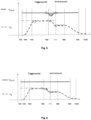
Figur 5 Skizze zum Phasenausgleich der Spindel auf eine Satzgrenze hin, -
Figur 6 Skizze zum Phasenausgleich durch zeitlich begrenzten Absenkung des Vorschub Niveaus auf eine Satzgrenze hin, -
Figur 7 Skizze zum nachgelagerten Phasenausgleich bei dynamisch nicht möglicher Trajektorienplanung zur programmierten Satzgrenze, -
Figur 8 Skizze einer Oberfläche eines Fräswerkstückes hergestellt mit einem Fräsverfahren nach Stand der Technik. - NC-Programme beschreiben die Fräsbahn in einer Sequenz einfacher Geometrieelemente. (Bahn-) Stützpunkte oder Bahnstützpunkte sind die jeweiligen Grenzen zwischen zwei aufgeiender folgenden Geometrieelementen. Diese Koordinaten werden dem NC-Programm pro Zeile als NC-Satz entnommen. Der Bahnparameter (auch als Bahnlängenintegral bezeichnet) beschreibt genau einen Punkt auf der im Teileprogramm beschriebenen Bahn, der durchaus zwischen den Stützpunkten der NC-Sätze liegen kann
- Als Synchronpunkt wird nachfolgend ein beliebiger Punkt der Bahn (=Bahnparameter) verstanden, an dem gleichzeitig gilt:
- nSpdl = nprog (die Drehzahl der Spindel ist auf dem im Programm vorgegebenen Wert)
- vb = vprog (die Vorschubgeschwindigkeit ist auf dem im Programm vorgegebenen Wert)
- ϕSpdl = ϕprog (die Winkellage (Phase) der Spindel ist auf dem im Programm vorgegebenen Wert)
- aSpdl = 0 (die Spindeldrehzahl ist konstant)
- ab = 0 (die Spindel wird translatorisch in x, y, z Richtung nicht beschleunigt)
- Unter einem Triggerpunkt wird hier der Beginn (in Zeit und/oder Bahnparameter) für die Planung eines Bewegungsprofils auf einen Synchronpunkt hin.
- Mit dem programmieren eines Vorschubs und einer Spindeldrehzahl in einem NC-Programm einer CNC-Steuerung wird ein technologisch bedingter Zahnvorschub durch festgelegt. Aufgabe einer jeden CNC ist es, im Grundsatz, diesen programmierten (Wunsch- bzw. Maximal-) Vorschub, unter Einhaltung der dynamischen Grenzwerte der beteiligten Achsen möglichst genau einzuhalten ohne diesen Maximalwert zu überschreiten. In Bereichen von Bahnkrümmungen muss das Vorschubniveau abgesenkt werden um die Achsvorschubantriebe nicht dynamisch zu überfordern oder auch um gewisse Anforderungen an die Bahngenauigkeit einzuhalten. Realisiert wird dies durch die Vorausberechnung eines sog. Geschwindigkeitsgrenzwertprofils im Rahmen der sog. Bahnplanung, wie dies in
Figur 1 gezeigt ist. - Jede Programmzeile ist in
Figur 1 sowie im folgenden Text in Anlehnung an Din/Iso bzw. G-Code mit N10, N20 und so fort bis N100 bezeichnet. Für jede Programmzeile wird durch eine CNC Steuerung nach Stand der Technik eine Maximalgeschwindigkeit des Vorschubes als Geschwindigkeitsgrenzwertprofil der Bahnplanung ermittelt. Das Geschwindigkeitsgrenzwertprofil enthält den im NC-Programm programmierten Vorschub bzw. Die Vorschubgeschwindigkeit v lim, prog sowie als Ergebnis der Bahnverlaufsanalyse die dynamisch bedingten Maximalwerte für die Bahngeschwindigkeit innerhalb des Satzes v lim, dyn sowie die maximale Übergangsgeschwindigkeit pro Satzübergang v lim, über. - Aufgabe des nachgelagerten, sog. Geschwindigkeitsprofilgenerators ist es, ein Geschwindigkeitsprofil über dem Bahnparameter (oder der Zeit, je nach Implementierung) zu berechnen, das sich den Minimalwerten des Grenzwertprofils von unten her, also von geringeren Werten, da der Maximalwert ja nicht überschritten warden darf, durch tangentenstetige Geschwindigkeitsverläufe auf möglichst hohem Niveau anschmiegt, dabei aber das Grenzwertprofil an keiner Stelle überschreitet. Wird eine Darstellung über der Zeit gewählt, so ergeben sich für das Geschwindigkeitsprofil Polynomsegmente 2. Ordnung, deren Segmentgrenzen im allgemeinsten Fall weder exakt auf einer Satzgrenze noch auf einem Zeitpunkt der später durch den Interpolator abgetastet wird, liegen, wie dies in
Figur 2 dargestellt ist. Die Geschwindigkeit v B ist an jeder Stelle unterhalb der inFigur 1 dargestellten Werte von v lim, prog, v lim,dyn sowie v lim, über. - Abschließend wird das so vorausgerechnete Geschwindigkeitsprofil vom sog. Abtastinterpolator in der Zykluszeit des sog. Interpolationstakes als IPO-Abtastpunkte abgetastet und die Lagesollwerte für sämtliche an der Bewegung beteiligten Vorschubachsen berechnet. Dadurch ergibt sich auch, dass nicht jeder NC-Stützpunkt exakt als Lagesollwert an den Achsregler ausgegeben wird, weil die exakte NC-Satzgrenze im allgemeinsten Fall zwischen zwei IPO-Abtastpunkten zu liegen kommt. Die Abtastung ist schematisch in
Figur 3 dargestellt. Mit einem Zeitintervall Ta warden Lagewerte sb durch entsprechende Wegsensoren aller Achsen ermittelt und an die Steuerung weitergegeben. - Die zuvor dargestellte Ermittlung des Geschwindigkeitsprofils und die sich daraus ergebende Steuerung der Vorschübe aller Achsen sind aus dem Stand der Technik bekannt.
- Der Drehzahlverlauf einer lagegeregelten Spindel wird erfindungsgemäß über dem Bahnverlauf ermittelt und gesteuert. Zudem wird der Winkel (Phase) der Spindel an bestimmten Stellen auf einen vorgegebenen Wert gesteuert. Eine grafische Darstellung lehnt sich an die des Bahngeschwindigkeitsprofils an.
- Die Geschwindigkeit einer lagegeregelten Spindel kann erfindungsgemäß, wie ein Bahngeschwindigkeitsprofil in derselben Darstellung eines Geschwindigkeitsplans über dem Bahnparameter (oder der Zeit) wie in
Figur 4 dargestellt abgebildet werden. Die zyklischen Lagesollwerte können dann von beiden Profilen zeitgleich abgetastet werden. - Durch ein solches Verfahren ist jedem interpolierten Bahnpunkt exakt eine Spindelorientierung (d. h. ein Winkel der Spindel relativ zu einem Nullpunkt; eine Phase der Rotation der Spindel) zugeordnet. Insbesondere herrscht in den Bereichen konstanten Bahnvorschubs und konstanter Spindeldrehzahl eine "Quasi-Getriebe-Synchronität" zwischen Spindeldrehzahl und Bahngeschwindigkeit. Allerdings besteht in dem Zustand der exakten Geschwindigkeitskopplung zwischen Spindel und Bahn für die Spindel noch der Freiheitsgrad der Spindelorientierung in Bezug zum Bahnlängenintergral, der mathematisch als Integrationskonstante aufgefasst werden kann. Erfindungsgemäß wird dieser Freiheitsgrad mit Zielparametern versehen (=programmiert) und unter Einhaltung der Dynamikgrenzen zeitoptimal hergestellt.
- Für die Versorgung mit den Zielparametern wird an mindestens einem Punkt auf der Bahn eine exakte Spindelorientierung zugeordnet. Erfindungsgemäß findet diese Zuordnung besonders Vorteilhaft im NC-Programm statt. Die Programmierung einer solchen Synchronisationsbedingung führt mindestens (
Fig. 5 ) einmal pro benachbart liegender Fräsbahn zu einer festgelegten Spindelorientierung. Bei gegebenen Synchronisationsbefehlen, besteht die Aufgabe des erfindungsgemäßen Verfahrens zunächst darin, zu ermitteln ob eine Trajektorienplanung unter Einhaltung der Dynamikgrenzwerte möglich ist. Für den Fall, dass eine Trajektorienplanung möglich ist, werden nachfolgend zwei mögliche Verfahren zur Herstellung der Synchronität beschrieben. Darüber hinaus wird ein Verfahren angegeben wie vorteilhaft mit dem Fall umgegangen werden kann, dass eine Trajektorienplanung nicht möglich ist. - Für die weiteren Ausführungen werden als gegeben, (oder zunächst herzustellende Systemeigenschaften des CNC Steuerungssystems) vorausgesetzt:
Erfindungsgemäß wird einem bestimmten geometrischen Ort auf der Bahn eine an dieser Stelle gewünschte Spindel-Winkellage zugeordnet. In Ausführungsbeispielen der Erfindung wird dies realisiert, indem im CNC Programm ein zusätzlicher (ggf. zur reinen Bahnbeschreibung redundanter) NC-Satz Stützpunkt dem Teileprogramm hinzufügt wird. Hier ein Beispiel für eine (von vielen denkbaren) Syntaxerweiterung eines DIN/ISO gemäßen NC Programms, diese ist in Zeile N40 mit "G119 S77" eingefügt und dort als Kommentar erläutert: - N10 M03 S1000
- N20 G00 X-110 Y0 Z10
- N30 G01 Z-1 F2000
- N40 G01 X-100 G119 S77; an der Position X-100 soll die Spindel auf 77° stehen
- N50 G01 X+100
- Die Syntaxerweiterung stellt einen Befehl G119 zur Verfügung, der einen Parameter S mit der Angabe einer Winkellage der Spindel relativ zu einem Nullpunkt (Phasenlage) erwartet.
- Dadurch entsteht bei konstantem Vorschub und konstanter Spindeldrehzahl eine "Quasi-Getriebe-Synchronität" zwischen dem Bahnlängenintegral und der Winkellage der Frässpindel. Diese Forderung ist in der Praxis wohl am Vorteilhaftesten durch einen lagegeregelten Betrieb der Frässpindel zu gewährleisten.
- Unter der Randbedingung der Einhaltung der Begrenzungen der drei Ableitungen des Weges nach der Zeit (vmax, amax, jmax) für alle Vorschubachsen sowie die Frässpindel, existiert für jeden Bewegungszustand der Bahnachsen und der Frässpindel eine minimal erforderliche Zeitdauer (und mithin auch ein Mindestweg auf der Fräsbahn) der erforderlich ist, um einen Synchronpunkt zu erreichen. Umgekehrt bedeutet das, dass es physikalisch nicht möglich ist, jeden beliebigen Synchronisierungswunsch in beliebig kurzer Zeit oder Weg herzustellen. Deshalb muss das zu beschreibende Verfahren auch erläutern, was in solchen Fällen passiert.
- Im Gegensatz zu linearen Vorschubachsen, interessiert für die vorliegende Aufgabenstellung die kumulierte Position der Frässpindel seit Beginn deren Bewegung nicht. Vielmehr interessieren lediglich die Winkellagen innerhalb des 0..360° Modulo Bereichs. Das heißt der maximal erforderliche Phasenausgleich für die Frässpindel zur Erreichung des Synchronisationsziels beträgt:

- Eine weitere Besonderheit für den lagegeregelten Betrieb von Spindeln mit Sollwertvorgabe im Modulobereich liegt drin, dass jede Sollposition auf zwei Arten erreicht werden kann (vorwärts oder rückwärts drehend.) Ist die Information über die Drehrichtung bekannt, so funktioniert die Lagevorgabe bis zu 360° / TA. Sprich, bei einem Interpolationstakt von 1ms bis zu 60.000 Umdr./min Spindeldrehzahl.
- Wenn die Trajektorienplanung möglich ist, können zwei Verfahren angewandt werden.
- Bei einem ersten Verfahrenerfolgt ein phasenausgleich durch die Spindel Aus der Definition eines Synchronpunktes ergibt sich, dass Synchronpunkte nur an solchen geometrischen Orten auf der Bahn (Bahnparameter) liegen können, in denen eine konstante Vorschubgeschwindigkeit zustande kommt. Per Definition des oben erläuterten Anschmiegungsproblems können solche Synchronpunkte genau dann exakt auf einer Satzgrenze zu liegen kommen, wenn der Brems-oder Beschleunigungsweg auf der Bahn ausreicht, um bei Satzeintritt zusätzlich zu vb = vprog, auch die Bedingung ab = 0 einzuhalten und wenn dieser Brems-oder Beschleunigungsweg bzw. dessen Dauer zusätzlich ausreichend ist, um den erforderlichen Phasenausgleich der Spindel herzustellen.
- Ein solcher Fall wird in der nachfolgenden Darstellung aufgezeigt:
- ........N10 M03 S1000:
- :
- N30 G00 X5 Y0 Z-5 F2000
- N40 G00 X10 Y10 Z-1
- N50 G00 X15 Y5
- N60 G01 X85
- N70 G01 X100 Y90 Z-2 F1500 G119 S77;Spindel auf 77° synchronisieren
- N80 G01 X150
- Die einzelnen Programmzeilen sind wie zuvor mit N10, N20 und so fort bezeichnet. Die Programmzeile N70 enthält neben dem Bahnweg zu X=100, Y=90 bei einer Tiefenposition Z=-2 und einer Vorschubgeschwindigkeit von 2000 die Information, dass die Spindel dort einen Winkel von 77° einnehmen soll.
- Die schaffierte Fläche in
Figur 5 ist das Geschwindigkeit-Zeit-Integral, das der erforderlichen Phasenkorrektur der Spindelposition entspricht. Eingekreist sind die jeweiligen Segmentgrenzen der Geschwindigkeitsprofile. Für diesen Fall ist das Verfahren ohne Beeinflussung der Vorschubplanung zeitoptimal und gänzlich ohne negativen Einfluss auf die Gesamtbearbeitungszeit des Teileprogramms. Zur Berechnung des Synchronisationsvorganges ist wie folgt vorzugehen: Nachdem im Look-Ahead Puffer ein (neuer) NC-Satz mit Orientierungsbedingung für die Spindel aufgefunden wird, wird -ähnlich wie wenn ein "normaler" neuer NC-Satz herein kommt- zusätzlich zum Bahngeschwindigkeitsprofil das Spindeldrehzahlprofil neu durchgerechnet. - Da der Look-Ahead Prozess mit der Geschwindigkeitsprofilgenerierung im Interpolator in Echtzeit läuft, ist der im letzten Takt an die Spindel ausgegebene Lagesollwert bekannt, ebenso der exakte Bahnparameter und somit auch die Dauer (in Bahn-Fahrweg und Zeit) bis zum Erreichen des Synchronpunktes. Damit kann die Winkelstellung der Spindel am Synchronpunkt berechnet werden, wenn ohne Korrektur der Spindeldrehzahl weitergefahren würde. Der erforderliche Betrag des Phasenausgleichs ist dann die Differenz dieser beiden Winkelpositionen im Modulokreis. Für den Fall von mehrschneidigen Werkzeugen, kann der erforderliche Phasenausgleich natürlich auch auf Winkelpositionen 360°/Anz Schneiden verkürzt werden. Mit Kenntnis der dynamischen Grenzwerte der Spindel lässt sich dann ein Spindel-Drehzahl-Profil errechnen, das den Synchronpunkt genau zur Satzgrenze herstellt Sollte der Bahnvorschub (wie in unserem Bespiel) während der Phasenkorrektur der Spindel nicht konstant sein, so ist es wichtig, dass der Synchronisierungsvorgang der Spindel exakt an der Satzgrenze endet.
- Bei einem zweiten Ausführungsbeispiel des erfindungsgemäßen Verfahrens erfolgt der phasenausgleich durch zeitlich begrenzte Absenkung des Vorschub Niveaus, siehe
Figur 6 . - Das Verfahren zur zeitlich begrenzten Absenkung des Vorschubniveaus des Geschwindigkeitsprofils ist insbesondere bei schnelllaufenden Spindeln effizient. Die erforderliche Höhe und Dauer der Vorschubabsenkung fallen gering aus weil die Spindel im Bereich von Millisekunden praktisch jede Winkelposition einnimmt, ohne die Spindeldrehzahl zu variieren. Zur Berechnung des Synchronisationsvorganges wird wie folgt vorgegangen: Die erforderliche Phasenkorrekturbetrag wird zunächst wie im vorgenannten Verfahren ermittelt. Nach der Berechnung der erforderlichen Phasenkorrektur bis zum Synchronpunkt wird ein modifiziertes Stück Geschwindigkeitsprofil auf den Synchronpunkt hin so berechnet, dass der Bewegungsabschnitt genau soviel zusätzliche Zeit (gegenüber der ursprünglichen Planung) benötigt, wie die Spindel zum Überstreichen der erforderlichen Phasenkorrektur benötigt.
- Eine Trajektorienplanung ist immer dann unmöglich, wenn Weg, bzw. Zeit nicht ausreichen, um eine Trajektorie zu finden. Das erfindungsgemäße Verfahren sieht für einen solchen Fall vor, einen nachgelagerten Synchronpunkt zu ermitteln, der auf der Bahn eine gewisse Distanz ... d vom programmierten Synchronpunkt (nachgelagert) entfernt ist. Die gewählte Distanz ... d ist dabei ein ganzzahliges Vielfaches des geplanten Zahnvorschubes, der aus dem S und F Wort bekannt ist. Das S Wort steuert die Spindeldrehzahl, das F Wort die Vorschubgeschwindigkeit. Damit kommt eine Synchronität der Werkzeugschneideneingriffe zwar verspätet, aber immer noch definiert zu einem im NC-Programm programmierten geometrischen Ort zustande. Bei gut gefülltem Look-ahead Puffer und nicht allzu eng aufeinander folgenden NC-Sätzen mit Synchronbedingung dürfte dieser Fall in der Praxis eher selten oder gar nicht zum Tragen kommen. Am leichtesten ließe er sich mit zu eng aufeinander folgenden NC-Sätzen mit Synchronbedingung "provozieren". Ein solcher Fall wird in der nachfolgenden Darstellung exemplarisch aufgezeigt: Bei einem programmierten Vorschubniveau gibt es keine Möglichkeit binnen der Distanz von X 0,1mm die Orientierung der Spindel unter Einhaltung der Dynamikgrenzwerte um 64° zu ändern, siehe dazu
Figur 7 ;
........N10 M03 S1000: - N30 G00 X5 Y0 Z-5 F2000
- N40 G00 X10 Y10 Z-1
- N50 G00 X15 Y5
- N60 G01 X85
- N70 G01 X100 Y90 Z-2 F1500 G119 S77;Spindel auf 77° synchronisieren
- N80 G01 X100,1 Y90 Z-2 G119 S13;Spindel auf 13° synchronisieren
- N90 G01 X150
-
- s Lage, Position, Weg
- v Geschwindigkeit
- a Beschleunigung
- j Ruck
- ϕ Winkellage
- n Drehzahl
- TA Interpolations Zykluszeit (IPO-Takt)
-
- b Bahn, Werte die sich auf die NC-Bahn beziehen
- Spdl Spindel, Werte die sich auf die Bahn beziehen
- prog (im NC-Programm) programmierter Wert
Claims (12)
- Verfahren zur Bearbeitung eines Werkstückes mit einem Fräswerkzeug, das an einer drehbaren Spindel angeordnet ist, wobei die Spindel gegenüber dem Werkstück oder das Werkstück gegenüber der Spindel entlang eines Bearbeitungsweges verschoben wird und die Spindel dabei um eine Spindelachse rotiert, wobei eine Drehzahl und/oder eine Phasenlage der Rotation der Spindel entlang des Bearbeitungsweges gesteuert wird, dadurch gekennzeichnet, dass der Bearbeitungsweg zeilenförmige parallele Bahnen umfasst und die Phasenlage der Spindel entlang des Bearbeitungsweges in benachbarten Bahnen im Wesentlichen gleich ist, wobei die Phasenlage durch Variation der Drehzahl der Spindel und/oder der Vorschubgeschwindigkeit der Spindel gegenüber dem Werkstück entlang des Bearbeitungsweges gesteuert wird.
- Verfahren nach Anspruch 1, dadurch gekennzeichnet, dass die Drehzahl und/oder die Phasenlage entlang des Bearbeitungsweges an mindestens einem Synchronpunkt auf einen vorgegebenen Sollwert gesteuert wird.
- Verfahren nach Anspruch 2, dadurch gekennzeichnet, dass die Drehzahl und/oder die Phasenlage entlang des Bearbeitungsweges an mehreren Synchronpunkten auf einen jeweils vorgegebenen Sollwert gesteuert wird.
- Verfahren nach Anspruch 2 oder 3, dadurch gekennzeichnet, dass vor Erreichen eines Synchronpunktes an einem Triggerpunkt mit der Steuerung von Drehzahl und Phasenlage auf den Sollwert begonnen wird.
- Verfahren einem der vorhergehenden Ansprüche, dadurch gekennzeichnet, dass die Phasenlage durch Absenken oder Erhöhen der Spindeldrehzahl gesteuert wird.
- Verfahren nach einem der vorhergehenden Ansprüche, dadurch gekennzeichnet, dass die Phasenlage durch Absenken oder Erhöhen der Vorschubgeschwindigkeit der Spindel gegenüber dem Werkstück entlang des Bearbeitungsweges gesteuert wird.
- Verfahren nach einem der vorhergehenden Ansprüche, dadurch gekennzeichnet, dass die Phasenlage bei einem Fräswerkzeug mit mehreren Schneiden um ein Vielfaches der Teilung der Schneiden verschoben ist.
- Vorrichtung zur Durchführung eines Verfahrens nach einem der vorhergehenden Ansprüche, dadurch gekennzeichnet, dass diese Mittel zur Verschiebung eines Werkstücks relativ zu einem an einer Spindel angeordneten Fräswerkzeug sowie Mittel zur Drehzahlsteuerung und Phasensteuerung der Rotation der Spindel umfasst.
- Vorrichtung nach Anspruch 8, dadurch gekennzeichnet, dass die Spindel durch einen lagegeregelten Elektromotor angetrieben wird.
- Vorrichtung nach Anspruch 8 oder 9, dadurch gekennzeichnet, dass diese Mittel zur Bestimmung der Winkelstellung der Spindel umfasst.
- Computerprogramm zur Ausführung eines Verfahrens nach einem der Ansprüche 1 bis 7.
- Datenstruktur zur Kodierung eines Computerprogramms zur Ausführung eines Verfahrens nach einem der Ansprüche 1 bis 7.
Priority Applications (1)
| Application Number | Priority Date | Filing Date | Title |
|---|---|---|---|
| HRP20231534TT HRP20231534T1 (hr) | 2018-07-09 | 2019-07-03 | Postupak glodanja |
Applications Claiming Priority (2)
| Application Number | Priority Date | Filing Date | Title |
|---|---|---|---|
| DE102018116553.6A DE102018116553B4 (de) | 2018-07-09 | 2018-07-09 | Fräsverfahren |
| PCT/EP2019/067869 WO2020011623A1 (de) | 2018-07-09 | 2019-07-03 | Fräsverfahren |
Publications (3)
| Publication Number | Publication Date |
|---|---|
| EP3821307A1 EP3821307A1 (de) | 2021-05-19 |
| EP3821307B1 true EP3821307B1 (de) | 2023-08-30 |
| EP3821307C0 EP3821307C0 (de) | 2023-08-30 |
Family
ID=67185015
Family Applications (1)
| Application Number | Title | Priority Date | Filing Date |
|---|---|---|---|
| EP19736669.3A Active EP3821307B1 (de) | 2018-07-09 | 2019-07-03 | Fräsverfahren |
Country Status (11)
| Country | Link |
|---|---|
| US (1) | US11507050B2 (de) |
| EP (1) | EP3821307B1 (de) |
| JP (1) | JP7065213B2 (de) |
| KR (1) | KR102379284B1 (de) |
| CN (1) | CN112513752B (de) |
| DE (1) | DE102018116553B4 (de) |
| ES (1) | ES2965775T3 (de) |
| HR (1) | HRP20231534T1 (de) |
| HU (1) | HUE064291T2 (de) |
| PL (1) | PL3821307T3 (de) |
| WO (1) | WO2020011623A1 (de) |
Families Citing this family (2)
| Publication number | Priority date | Publication date | Assignee | Title |
|---|---|---|---|---|
| JP7648893B2 (ja) * | 2021-05-31 | 2025-03-19 | 株式会社ジャノメ | 経路教示データ作成装置及びその方法並びにプログラム |
| CN113798566B (zh) * | 2021-09-01 | 2024-03-29 | 上海东岩机械股份有限公司 | 一种螺旋铣削方法 |
Family Cites Families (12)
| Publication number | Priority date | Publication date | Assignee | Title |
|---|---|---|---|---|
| JPH09218706A (ja) * | 1996-02-14 | 1997-08-19 | Toyota Motor Corp | 加工方法とそのためのプログラム作成装置および加工装置 |
| JP3631593B2 (ja) * | 1997-08-20 | 2005-03-23 | トヨタ自動車株式会社 | カッタパス設定方法 |
| JP3954723B2 (ja) * | 1998-04-28 | 2007-08-08 | トヨタ自動車株式会社 | 加工方法、加工装置およびデータ作成装置 |
| SE531858C2 (sv) * | 2007-12-21 | 2009-08-25 | Sandvik Intellectual Property | Fräsverktyg för spånavskiljande bearbetning, samt skärkropp och grundkropp härför |
| DE102010060220B4 (de) * | 2010-10-28 | 2013-07-11 | Gebr. Heller Maschinenfabrik Gmbh | Verfahren zur Bearbeitung von Freiformflächen |
| WO2013061445A1 (ja) * | 2011-10-27 | 2013-05-02 | 三菱電機株式会社 | 数値制御装置 |
| CN103576610A (zh) * | 2012-08-03 | 2014-02-12 | 德马吉森精机株式会社 | 机床、加工方法、程序和nc数据生成装置 |
| CN103042434B (zh) * | 2012-12-08 | 2014-12-10 | 华中科技大学 | 超精密铣削加工表面形貌纹理控制方法 |
| JP5855715B1 (ja) | 2014-08-07 | 2016-02-09 | ファナック株式会社 | 工作機械 |
| JP2017001153A (ja) * | 2015-06-12 | 2017-01-05 | 東芝機械株式会社 | エンドミルを用いた加工システム及び加工方法 |
| US9776255B2 (en) * | 2015-10-01 | 2017-10-03 | Delcam Limited | System and method for machining blades, blisks and aerofoils |
| JP6740199B2 (ja) | 2017-10-30 | 2020-08-12 | ファナック株式会社 | 数値制御装置、cnc工作機械、数値制御方法及び数値制御用プログラム |
-
2018
- 2018-07-09 DE DE102018116553.6A patent/DE102018116553B4/de not_active Expired - Fee Related
-
2019
- 2019-07-03 PL PL19736669.3T patent/PL3821307T3/pl unknown
- 2019-07-03 EP EP19736669.3A patent/EP3821307B1/de active Active
- 2019-07-03 HR HRP20231534TT patent/HRP20231534T1/hr unknown
- 2019-07-03 CN CN201980040339.5A patent/CN112513752B/zh active Active
- 2019-07-03 KR KR1020217000475A patent/KR102379284B1/ko not_active Expired - Fee Related
- 2019-07-03 HU HUE19736669A patent/HUE064291T2/hu unknown
- 2019-07-03 ES ES19736669T patent/ES2965775T3/es active Active
- 2019-07-03 US US17/258,554 patent/US11507050B2/en active Active
- 2019-07-03 JP JP2020569133A patent/JP7065213B2/ja not_active Expired - Fee Related
- 2019-07-03 WO PCT/EP2019/067869 patent/WO2020011623A1/de not_active Ceased
Also Published As
| Publication number | Publication date |
|---|---|
| US11507050B2 (en) | 2022-11-22 |
| JP7065213B2 (ja) | 2022-05-11 |
| ES2965775T3 (es) | 2024-04-16 |
| KR102379284B1 (ko) | 2022-03-25 |
| US20210149368A1 (en) | 2021-05-20 |
| PL3821307T3 (pl) | 2024-03-04 |
| CN112513752B (zh) | 2022-11-04 |
| WO2020011623A1 (de) | 2020-01-16 |
| DE102018116553A1 (de) | 2020-01-09 |
| KR20210029773A (ko) | 2021-03-16 |
| JP2021524386A (ja) | 2021-09-13 |
| EP3821307A1 (de) | 2021-05-19 |
| CN112513752A (zh) | 2021-03-16 |
| EP3821307C0 (de) | 2023-08-30 |
| DE102018116553B4 (de) | 2020-11-05 |
| HUE064291T2 (hu) | 2024-02-28 |
| HRP20231534T1 (hr) | 2024-03-01 |
Similar Documents
| Publication | Publication Date | Title |
|---|---|---|
| DE102018002566B4 (de) | Steuervorrichtung für eine Oszillationschneiden durchführende Werkzeugmaschine | |
| EP3552744B1 (de) | Vorrichtung und verfahren zur anfasbearbeitung eines werkstücks | |
| EP2221693B1 (de) | Verfahren und Vorrichtung zum Erzeugen von Steuerdaten zum Steuern eines Werkzeugs an einer zumindest 5 Achsen umfassenden Werkzeugmaschine | |
| DE102015112577B4 (de) | Werkzeugmaschine | |
| EP2895290B1 (de) | Verfahren zum modifizieren der flanken eines zahns eines zahnrads mit hilfe eines werkzeugs | |
| EP3552743A1 (de) | Vorrichtung und verfahren zur anfasbearbeitung eines verzahnten werkstücks | |
| EP1864739B1 (de) | Vorrichtung und Verfahren zur Weichbearbeitung von Kegelrädern und Verwendung der Vorrichtung | |
| DE112014007112B4 (de) | Numerisch gesteuerte Vorrichtung | |
| EP2338640A1 (de) | Maschine zur Bearbeitung von optischen Werkstücken, insbesondere von Kunststoff-Brillengläsern | |
| DE102016003049B4 (de) | Numerische Steuerung zur Ausführung reziproken Drehens in komplex fixiertem Zyklus | |
| DE102013112232B3 (de) | Verfahren zur Bearbeitung eines Rohteils mittels eines Werkzeuges | |
| EP3945381A1 (de) | Herstellung durch kegelsegmente bestimmbarer flächen mittels einer werkzeugmaschine | |
| DE102020117709A1 (de) | Zahnradbearbeitungsunterstützungsvorrichtung und Zahnradbearbeitungsvorrichtung | |
| DE69110583T2 (de) | Numerische steuerung. | |
| DE102018116553B4 (de) | Fräsverfahren | |
| EP3341802B1 (de) | Verfahren zum erzeugen oder bearbeiten von verzahnungen an werkstücken | |
| DE3522977A1 (de) | Verfahren zum umfangsprofilieren eines werkstueckes | |
| EP1369759B1 (de) | Bahnsteuerungsverfahren einer numerisch gesteuerten Maschine | |
| DE19821557A1 (de) | Verfahren zur nichtlinearen Darstellung von Bahnkurven | |
| EP4246257A1 (de) | Geschwindigkeitsabhängiges überschleifen zwischen sätzen mit unstetigen bahnverläufen | |
| DE102017011602B4 (de) | Numerische Steuerung | |
| EP4246256A1 (de) | Werkstückbearbeitung mit optimierter spindeldrehzahl in abhängigkeit eines schnittpunktes | |
| EP2135143A1 (de) | Verfahren und einrichtung zur bewegungsführung eines bewegbaren maschinenelements einer numerisch gesteuerten maschine | |
| DE2226547A1 (de) | Proportional Interpolator fur Mehr achsenmaschinen | |
| EP0563412B1 (de) | Werkzeugmaschine mit einer numerischen Steuerung zur Unterbrechung und Fortsetzung der Bearbeitung |
Legal Events
| Date | Code | Title | Description |
|---|---|---|---|
| STAA | Information on the status of an ep patent application or granted ep patent |
Free format text: STATUS: UNKNOWN |
|
| STAA | Information on the status of an ep patent application or granted ep patent |
Free format text: STATUS: THE INTERNATIONAL PUBLICATION HAS BEEN MADE |
|
| PUAI | Public reference made under article 153(3) epc to a published international application that has entered the european phase |
Free format text: ORIGINAL CODE: 0009012 |
|
| STAA | Information on the status of an ep patent application or granted ep patent |
Free format text: STATUS: REQUEST FOR EXAMINATION WAS MADE |
|
| 17P | Request for examination filed |
Effective date: 20210202 |
|
| AK | Designated contracting states |
Kind code of ref document: A1 Designated state(s): AL AT BE BG CH CY CZ DE DK EE ES FI FR GB GR HR HU IE IS IT LI LT LU LV MC MK MT NL NO PL PT RO RS SE SI SK SM TR |
|
| DAV | Request for validation of the european patent (deleted) | ||
| DAX | Request for extension of the european patent (deleted) | ||
| GRAP | Despatch of communication of intention to grant a patent |
Free format text: ORIGINAL CODE: EPIDOSNIGR1 |
|
| STAA | Information on the status of an ep patent application or granted ep patent |
Free format text: STATUS: GRANT OF PATENT IS INTENDED |
|
| INTG | Intention to grant announced |
Effective date: 20230228 |
|
| GRAS | Grant fee paid |
Free format text: ORIGINAL CODE: EPIDOSNIGR3 |
|
| GRAA | (expected) grant |
Free format text: ORIGINAL CODE: 0009210 |
|
| STAA | Information on the status of an ep patent application or granted ep patent |
Free format text: STATUS: THE PATENT HAS BEEN GRANTED |
|
| AK | Designated contracting states |
Kind code of ref document: B1 Designated state(s): AL AT BE BG CH CY CZ DE DK EE ES FI FR GB GR HR HU IE IS IT LI LT LU LV MC MK MT NL NO PL PT RO RS SE SI SK SM TR |
|
| REG | Reference to a national code |
Ref country code: GB Ref legal event code: FG4D Free format text: NOT ENGLISH |
|
| REG | Reference to a national code |
Ref country code: CH Ref legal event code: EP |
|
| REG | Reference to a national code |
Ref country code: DE Ref legal event code: R096 Ref document number: 502019009163 Country of ref document: DE |
|
| REG | Reference to a national code |
Ref country code: IE Ref legal event code: FG4D Free format text: LANGUAGE OF EP DOCUMENT: GERMAN |
|
| U01 | Request for unitary effect filed |
Effective date: 20230927 |
|
| U07 | Unitary effect registered |
Designated state(s): AT BE BG DE DK EE FI FR IT LT LU LV MT NL PT SE SI Effective date: 20231108 |
|
| PG25 | Lapsed in a contracting state [announced via postgrant information from national office to epo] |
Ref country code: GR Free format text: LAPSE BECAUSE OF FAILURE TO SUBMIT A TRANSLATION OF THE DESCRIPTION OR TO PAY THE FEE WITHIN THE PRESCRIBED TIME-LIMIT Effective date: 20231201 |
|
| PG25 | Lapsed in a contracting state [announced via postgrant information from national office to epo] |
Ref country code: IS Free format text: LAPSE BECAUSE OF FAILURE TO SUBMIT A TRANSLATION OF THE DESCRIPTION OR TO PAY THE FEE WITHIN THE PRESCRIBED TIME-LIMIT Effective date: 20231230 |
|
| PG25 | Lapsed in a contracting state [announced via postgrant information from national office to epo] |
Ref country code: RS Free format text: LAPSE BECAUSE OF FAILURE TO SUBMIT A TRANSLATION OF THE DESCRIPTION OR TO PAY THE FEE WITHIN THE PRESCRIBED TIME-LIMIT Effective date: 20230830 Ref country code: NO Free format text: LAPSE BECAUSE OF FAILURE TO SUBMIT A TRANSLATION OF THE DESCRIPTION OR TO PAY THE FEE WITHIN THE PRESCRIBED TIME-LIMIT Effective date: 20231130 Ref country code: IS Free format text: LAPSE BECAUSE OF FAILURE TO SUBMIT A TRANSLATION OF THE DESCRIPTION OR TO PAY THE FEE WITHIN THE PRESCRIBED TIME-LIMIT Effective date: 20231230 Ref country code: GR Free format text: LAPSE BECAUSE OF FAILURE TO SUBMIT A TRANSLATION OF THE DESCRIPTION OR TO PAY THE FEE WITHIN THE PRESCRIBED TIME-LIMIT Effective date: 20231201 |
|
| REG | Reference to a national code |
Ref country code: SK Ref legal event code: T3 Ref document number: E 42925 Country of ref document: SK |
|
| REG | Reference to a national code |
Ref country code: HU Ref legal event code: AG4A Ref document number: E064291 Country of ref document: HU |
|
| REG | Reference to a national code |
Ref country code: HR Ref legal event code: T1PR Ref document number: P20231534 Country of ref document: HR |
|
| REG | Reference to a national code |
Ref country code: ES Ref legal event code: FG2A Ref document number: 2965775 Country of ref document: ES Kind code of ref document: T3 Effective date: 20240416 |
|
| PG25 | Lapsed in a contracting state [announced via postgrant information from national office to epo] |
Ref country code: SM Free format text: LAPSE BECAUSE OF FAILURE TO SUBMIT A TRANSLATION OF THE DESCRIPTION OR TO PAY THE FEE WITHIN THE PRESCRIBED TIME-LIMIT Effective date: 20230830 |
|
| REG | Reference to a national code |
Ref country code: DE Ref legal event code: R097 Ref document number: 502019009163 Country of ref document: DE |
|
| PLBE | No opposition filed within time limit |
Free format text: ORIGINAL CODE: 0009261 |
|
| STAA | Information on the status of an ep patent application or granted ep patent |
Free format text: STATUS: NO OPPOSITION FILED WITHIN TIME LIMIT |
|
| REG | Reference to a national code |
Ref country code: HR Ref legal event code: ODRP Ref document number: P20231534 Country of ref document: HR Payment date: 20240703 Year of fee payment: 6 |
|
| PGFP | Annual fee paid to national office [announced via postgrant information from national office to epo] |
Ref country code: SK Payment date: 20240701 Year of fee payment: 6 |
|
| 26N | No opposition filed |
Effective date: 20240603 |
|
| U20 | Renewal fee for the european patent with unitary effect paid |
Year of fee payment: 6 Effective date: 20240724 |
|
| PGFP | Annual fee paid to national office [announced via postgrant information from national office to epo] |
Ref country code: HR Payment date: 20240703 Year of fee payment: 6 Ref country code: IE Payment date: 20240719 Year of fee payment: 6 |
|
| PGFP | Annual fee paid to national office [announced via postgrant information from national office to epo] |
Ref country code: ES Payment date: 20240801 Year of fee payment: 6 Ref country code: CH Payment date: 20240801 Year of fee payment: 6 |
|
| PGFP | Annual fee paid to national office [announced via postgrant information from national office to epo] |
Ref country code: CZ Payment date: 20240702 Year of fee payment: 6 |
|
| PGFP | Annual fee paid to national office [announced via postgrant information from national office to epo] |
Ref country code: PL Payment date: 20240702 Year of fee payment: 6 |
|
| PGFP | Annual fee paid to national office [announced via postgrant information from national office to epo] |
Ref country code: HU Payment date: 20240703 Year of fee payment: 6 |
|
| PGFP | Annual fee paid to national office [announced via postgrant information from national office to epo] |
Ref country code: RO Payment date: 20240703 Year of fee payment: 6 |
|
| PG25 | Lapsed in a contracting state [announced via postgrant information from national office to epo] |
Ref country code: MC Free format text: LAPSE BECAUSE OF FAILURE TO SUBMIT A TRANSLATION OF THE DESCRIPTION OR TO PAY THE FEE WITHIN THE PRESCRIBED TIME-LIMIT Effective date: 20230830 |
|
| GBPC | Gb: european patent ceased through non-payment of renewal fee |
Effective date: 20240703 |
|
| PG25 | Lapsed in a contracting state [announced via postgrant information from national office to epo] |
Ref country code: GB Free format text: LAPSE BECAUSE OF NON-PAYMENT OF DUE FEES Effective date: 20240703 |
|
| PG25 | Lapsed in a contracting state [announced via postgrant information from national office to epo] |
Ref country code: CY Free format text: LAPSE BECAUSE OF FAILURE TO SUBMIT A TRANSLATION OF THE DESCRIPTION OR TO PAY THE FEE WITHIN THE PRESCRIBED TIME-LIMIT; INVALID AB INITIO Effective date: 20190703 |
|
| REG | Reference to a national code |
Ref country code: HR Ref legal event code: PBON Ref document number: P20231534 Country of ref document: HR Effective date: 20250703 |
|
| PG25 | Lapsed in a contracting state [announced via postgrant information from national office to epo] |
Ref country code: CZ Free format text: LAPSE BECAUSE OF NON-PAYMENT OF DUE FEES Effective date: 20250703 |
|
| REG | Reference to a national code |
Ref country code: SK Ref legal event code: MM4A Ref document number: E 42925 Country of ref document: SK Effective date: 20250703 |
|
| REG | Reference to a national code |
Ref country code: CH Ref legal event code: H13 Free format text: ST27 STATUS EVENT CODE: U-0-0-H10-H13 (AS PROVIDED BY THE NATIONAL OFFICE) Effective date: 20260224 |
|
| PG25 | Lapsed in a contracting state [announced via postgrant information from national office to epo] |
Ref country code: HU Free format text: LAPSE BECAUSE OF NON-PAYMENT OF DUE FEES Effective date: 20250704 |
|
| U90 | Renewal fees not paid: noting of loss of rights |
Free format text: RENEWAL FEE NOT PAID FOR YEAR 07 Effective date: 20260224 |
|
| PG25 | Lapsed in a contracting state [announced via postgrant information from national office to epo] |
Ref country code: HR Free format text: LAPSE BECAUSE OF NON-PAYMENT OF DUE FEES Effective date: 20250703 |
|
| PG25 | Lapsed in a contracting state [announced via postgrant information from national office to epo] |
Ref country code: RO Free format text: LAPSE BECAUSE OF NON-PAYMENT OF DUE FEES Effective date: 20250703 |
|
| PG25 | Lapsed in a contracting state [announced via postgrant information from national office to epo] |
Ref country code: CH Free format text: LAPSE BECAUSE OF NON-PAYMENT OF DUE FEES Effective date: 20250731 |
|
| PG25 | Lapsed in a contracting state [announced via postgrant information from national office to epo] |
Ref country code: SK Free format text: LAPSE BECAUSE OF NON-PAYMENT OF DUE FEES Effective date: 20250703 |