EP3820787B1 - Fluid dispensing apparatus - Google Patents
Fluid dispensing apparatus Download PDFInfo
- Publication number
- EP3820787B1 EP3820787B1 EP19833812.1A EP19833812A EP3820787B1 EP 3820787 B1 EP3820787 B1 EP 3820787B1 EP 19833812 A EP19833812 A EP 19833812A EP 3820787 B1 EP3820787 B1 EP 3820787B1
- Authority
- EP
- European Patent Office
- Prior art keywords
- fluid
- user
- dose
- flexible
- button
- Prior art date
- Legal status (The legal status is an assumption and is not a legal conclusion. Google has not performed a legal analysis and makes no representation as to the accuracy of the status listed.)
- Active
Links
Images



Classifications
-
- B—PERFORMING OPERATIONS; TRANSPORTING
- B05—SPRAYING OR ATOMISING IN GENERAL; APPLYING FLUENT MATERIALS TO SURFACES, IN GENERAL
- B05B—SPRAYING APPARATUS; ATOMISING APPARATUS; NOZZLES
- B05B11/00—Single-unit hand-held apparatus in which flow of contents is produced by the muscular force of the operator at the moment of use
- B05B11/01—Single-unit hand-held apparatus in which flow of contents is produced by the muscular force of the operator at the moment of use characterised by the means producing the flow
- B05B11/10—Pump arrangements for transferring the contents from the container to a pump chamber by a sucking effect and forcing the contents out through the dispensing nozzle
- B05B11/1001—Piston pumps
- B05B11/1005—Piston pumps with means for adjusting or modifying pump stroke
- B05B11/1008—Piston pumps with means for adjusting or modifying pump stroke by adjusting or modifying the pump end-of-dispensing-stroke position
-
- B—PERFORMING OPERATIONS; TRANSPORTING
- B05—SPRAYING OR ATOMISING IN GENERAL; APPLYING FLUENT MATERIALS TO SURFACES, IN GENERAL
- B05B—SPRAYING APPARATUS; ATOMISING APPARATUS; NOZZLES
- B05B11/00—Single-unit hand-held apparatus in which flow of contents is produced by the muscular force of the operator at the moment of use
- B05B11/01—Single-unit hand-held apparatus in which flow of contents is produced by the muscular force of the operator at the moment of use characterised by the means producing the flow
- B05B11/10—Pump arrangements for transferring the contents from the container to a pump chamber by a sucking effect and forcing the contents out through the dispensing nozzle
- B05B11/1028—Pumps having a pumping chamber with a deformable wall
- B05B11/1032—Pumps having a pumping chamber with a deformable wall actuated without substantial movement of the nozzle in the direction of the pressure stroke
-
- B—PERFORMING OPERATIONS; TRANSPORTING
- B05—SPRAYING OR ATOMISING IN GENERAL; APPLYING FLUENT MATERIALS TO SURFACES, IN GENERAL
- B05B—SPRAYING APPARATUS; ATOMISING APPARATUS; NOZZLES
- B05B11/00—Single-unit hand-held apparatus in which flow of contents is produced by the muscular force of the operator at the moment of use
- B05B11/01—Single-unit hand-held apparatus in which flow of contents is produced by the muscular force of the operator at the moment of use characterised by the means producing the flow
- B05B11/02—Membranes or pistons acting on the contents inside the container, e.g. follower pistons
- B05B11/026—Membranes separating the content remaining in the container from the atmospheric air to compensate underpressure inside the container
Definitions
- the present invention relates to methods and devices for the accurate dispensing, tracking, and reordering of dispensed fluids.
- the technical problems solved by the present invention are: the delivery of information to users of fluids, ensuring that users of fluids use an accurate measurement(s) at the specified time, GPS location of fluid dispensing activity, accurate tracking of the time and dose, enable reminders for use and amount of the dosage to prevent overdose and to track compliance, and prompt for reorder to ensure ongoing compliance for which there is no current solution available, and communication of tracking information to the user, physicians, health care providers, retailers, manufacturers and others who wish to monitor usage, manage compliance, and reorder the fluid.
- Smart 1 TOUCH will integrate to electronic data collection, smart devices and audible data devices.
- US 2012/029433 A1 discloses a portable infusion device according to the prior art.
- the present invention solves the technical problems described above by either combining a mechanical measured fluid dispenser or sensor technology, such as Bluetooth or RFID, with hardware and software features that detect the time and amount of a fluid dispensing operation, and communicate that information to a user's smart phone app or software which can then optionally, and preferably according to a user-selection, communicate that information to the user's physician, pharmacy, retailers, manufacturers or other interested parties requiring compliance, monitoring and reordering capabilities.
- a mechanical measured fluid dispenser or sensor technology such as Bluetooth or RFID
- the mechanical or sensor based measured fluid dispenser of the type disclosed in, for example, U.S. Patent Nos. 8,123,073 , 7,419,322 , 8,387,833 , 10,259,645 and/or in U.S. Patent Application Serial No. 15/941/893 .
- the sensor or mechanical measured fluid dispenser may include a chip or other sensor configured to detecting a physical change caused by the depression of the dispenser's actuator.
- the sensor may be a pressure sensor, or a flow rate sensor, a timer, or some combination thereof.
- the sensor may be any single sensor or combination of sensors that provide information concerning the amount of fluid that is dispensed upon the activation of the dispenser's actuator. Accordingly, the sensor may be located inside or beneath the actuator itself, located somewhere in the fluid channel/pathway, or in dispenser case enclosures.
- the mechanical measured dispenser may include an adjustable dose mechanism according to which the amount of the dose may be adjusted by the user.
- one or more sensors may be provided to determine the adjustment state of the adjustable dose feature.
- the sensor that determines the adjustment state of the adjustable dose mechanism may be separate from and optionally in addition to the sensor(s) that detects and/or measures the amount of a dose when the dose actuator is actuated.
- the measured dosing device may be reusable, according to which it may be removed from a first fluid pouch when the first fluid pouch is empty and attached to a second fluid pouch with a fresh supply of fluid.
- the fluid pouches may include a smart label and/or RFID tag.
- a user may scan the smart label or RFID tag with a smart phone app which would then cause information concerning the fluid to be displayed to the user.
- information might include how to administer the fluid by using the the mechanical measured dispenser or pouch dispenser, how to use the app remind the user to administer the fluid, track compliance, location of where to reorder, automatically reorder, or identify location where fluid can be obtained, how to use the app to track transmit dosage and time information and/or to transmit such information to interested parties, according to the user's preferences and selections.
- the present invention provides a reliable and verifiable way for users of fluids to be automatically reminded to administer a dosage, for users to be sure that the appropriate dosage is being administered, and physician, pharmacy, retailers, manufacturers, or others requiring compliance, monitoring and reordering capabilities can reliably track and document usage.
- the present invention is a device for dispensing fluid from a pouch, the device capable of being set to different discrete and repeatable/equal dispensing amounts, depending on the amount of fluid required to be dispensed by the user for various applications and uses.
- the device may also be set to an "off" or “closed” position to prevent accidental dispensing of fluid when not in use.
- the device is preferably configured to be affixed to the outer surface of a fluid container, which fluid container is preferably a flexible bag or pouch. According to various embodiments, at least one surface of the fluid container or a sufficient portion of the fluid container is flexible to allow the container to collapse as fluid is withdrawn therefrom.
- the dispensing device is preferably attached to portion of the container that is flexible and which is collapsible as fluid is dispensed from the container.
- the device also includes one or more sensors configured to record, store and/or transmit one or more physical properties of the device, particularly when the dispensing device is actuated in order to dispense fluid and/or when the device is adjusted to a particular dose.
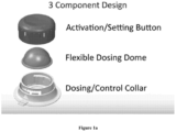
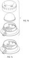
- Figures 1a-1c show an embodiment of the device including a dosing/control collar, a flexible dosing dome, and a combined dose setting dial and dose delivery button.
- the flexible dosing dome and the dosing/control collar when assembled, form the pump or dosing chamber.
- the dosing/control collar is preferably cylindrical in shape with concentric inner and outer annular shafts/columns rising from a common base and defining a narrow channel between them.
- the exterior of the outer annular shaft may feature a flange that extends away from the center of the shaft.
- the interior shaft also features a plurality of horizontal and vertical dosing and rotation channels or slots that receive and interact with corresponding nubs on the outside surface of the dose dial/button.
- the dosing and rotation channels may be on the shaft of the dose dial/button and the nubs may be on the outside surface of the inner annular shaft.
- the horizontal slots are the rotation slots and may have a plurality of détente locations so that the user can tactically feel the progress of the dial as it is being rotated.
- the vertical channels are the dosing slots and have differing depths (measured from the horizontal slot to the bottom of the vertical slot) which correspond to different dispensing amounts.
- each vertical slot in the inner annular shaft is paired with a second vertical slot of the same depth, spaced apart on the inner annular shaft, and each nub on the dose dial button is paired with a second nub spaced apart on the dose/dial button at a location that corresponds to the location of the second vertical shaft.
- the limit of depression limits the amount dispensed, and the depth of the vertical slot limits how far the button can be depressed because when the nub hits the bottom of the vertical slot, the dial/button is prevented from being depressed any further without breaking the nub, the slot/channel, or both.
- the dosing control collar also features a through-opening in the bottom surface to accommodate the entry of fluid, fluid inlet valve, represented in Figure 3 as a flexible flap that is configured to lie over the through-opening, a fluid outlet on the outside surface of the dosing control collar, and a fluid delivery channel between said fluid inlet and said fluid outlet.
- the dosing control collar may have separate dosing slots and return slots.
- the dosing slots may have downward facing teeth or prongs which prevent the nubs from traveling upwards, thus requiring that the dial/button be fully depressed before it returns to the set position. Since the nubs cannot travel upwards in the dosing slots, separate return slots are provided adjacent the dosing slots, connected by a horizontal slot.
- the return slots preferably have upward facing teeth or prongs to prevent the nubs from traveling downward while in the return slots.
- the dose setting dial/dose delivery button is preferably manufactured of relatively rigid plastic having a rigid bottom portion that snaps into the channel formed between the inner and outer annular shafts of the base (dosing/control collar).
- the dose setting dial/dose delivery button and the dosing/control collar are preferably made of a rigid plastic material. Nubs molded to or otherwise formed on the interior surface of the dial/button rest inside the slots formed in the interior shaft. When a user presses the dial/button, the dial/button forces the flexible dosing dome downward to evacuate the interior volume of the dome via the fluid outlet; when the dial/button is released, the flexible dosing dome returns to its original shape, forcing the dial/button upward, and drawing fluid into the interior of the dome under vacuum action.
- the flexible dosing dome is preferably made of shape memory elastomeric material that returns to its original shape after deformation.
- Figures 5a and 5b show these three parts assembled into an adjustable fluid dispensing device according to the invention in which the flexible dosing dome is sealed to the base inside the interior column of the dosing/control collar and the bottom portion of the dose setting dial/dose delivery button is snapped over the flexible dosing dome into the channel between the inner and outer shafts.
- the upper portion of the dial/button projects above the top of the dosing/control collar.
- the perimeter of the upper portion of the dial/button has molded or printed indicia such as "Open” "Closed” and "FULL” and "HALF" to indicate the rotary position of the dial that corresponds to various functions or dispensing amounts.
- each of these indicia corresponds to a nub/slot combination that permits no depression, full depression, half depression, or other partial depression to dispense a corresponding amount of fluid.
- the outside surface of the outer shaft of the collar preferably has printed or molded or other indicia indicating the location on the collar that must be lined up with the appropriate indicia on the dial/button in order to achieve the desired function.
- the dial/button is in the fully depressed position, and rotated counterclockwise so that the nubs on the inside surface of the dial/button are in the bottom horizontal slot, locking the dial/button into a closed position.
- the bottom horizontal slot has a slight downward slant before becoming horizontal to draw the dial/button down slightly as it is rotated into the closed position, see Figure 1c , causing the bottom surface of the dial button to bear down on the fluid delivery channel, pinching it shut.
- the indicia on the collar lines up with a " ⁇ Open” indicia on the button, showing that in order to dispense fluid, the dial/button must be rotated clockwise until the nubs line up with the "FULL" vertical slot. If the user wishes to dispense only a half dose, the dial/button must be rotated clockwise again until the nubs line up with the correspondingly shorter/shallower vertical channel/slot.
- Figures 6a, 6b and 6c show an alternative design of an adjustable fluid dispensing device according to the invention.
- the embodiment of Figures 6a, 6b and 6c contains a central screw that can be turned by the top dial portion for a continuous dose adjustment device. As the screw is turned, the maximum depression of the button of increased or decreased as the screw moves the button toward or away from the dosing control collar.
- a sensor or other smart chip may be arranged to detect the rotation and hence the dosage amount.
- Figures 7a and 7b show the adjustable metering device of the invention about to be connected to a flexible fluid container, preferably a bag or pouch.
- the fluid container is collapsible as fluid is dispensed therefrom and preferably contains no air.
- the bottom of the adjustable metering device has an adhesive that makes a secure and air-tight connection to the fluid container.
- the adhesive may be covered prior to use with a thin pull-away film to protect and preserve the adhesive until it is time to connect the device to the fluid container.
- the bottom of the adjustable metering device may be heat welded to the fluid container, sonic welded to the fluid container or sealed to the fluid container in any other known method.
- the fluid container may have a reinforced region and/or treated surface that corresponds to the shape and size of the device to facilitate strong and secure connection and prevent container breaking or tearing should a force or load be applied to the device after it has been attached to the fluid container.
- Figures 8a and 8b show an adjustable metering device of the invention connected to a flexible fluid container.
- the device can be operated to dispense fluid no matter the orientation of the device in space, as it is agnostic to gravity or other forces except for the depression of the dial/button.
- Compliance measured by actual pressure on the button and number of times pushed. Time and date captured. Ability to reorder when pouch is close to deletion.
- Smartphone application automatically track the dose size and time using either the mechanical or sensor technologies.
- Senor and app technologies allow for identification of reorder options using GPS technologies or online ordering applications.
- the fluid can be of any viscosity.
- RFID sensor stickers, Bluetooth and other sensor technologies are used.
- the user will download the app.
- the app will pick up the sensor signal from the sensor technology and prompt for educational and compliance engagement.
- the app will automatically capture dose, time of dose, prompt for next dose, and alert when near depletion, requiring a reorder.
- the app will alert when the dose is due.
- Pressure sensor in the "button” sends a signal that the fluid was dispensed and how much. 1TOUCH dispensing technology indicates dosage.
- Patient can provide permissions through the app to share with physician, pharmacy, retailers, manufacturers or others requiring compliance, monitoring and reordering capabilities.
- GPS enables realtime capabilities for reorder and retail practicalties.
Landscapes
- Containers And Packaging Bodies Having A Special Means To Remove Contents (AREA)
Description
- The present invention relates to methods and devices for the accurate dispensing, tracking, and reordering of dispensed fluids.
- The technical problems solved by the present invention are: the delivery of information to users of fluids, ensuring that users of fluids use an accurate measurement(s) at the specified time, GPS location of fluid dispensing activity, accurate tracking of the time and dose, enable reminders for use and amount of the dosage to prevent overdose and to track compliance, and prompt for reorder to ensure ongoing compliance for which there is no current solution available, and communication of tracking information to the user, physicians, health care providers, retailers, manufacturers and others who wish to monitor usage, manage compliance, and reorder the fluid. Smart 1 TOUCH will integrate to electronic data collection, smart devices and audible data devices.
US 2012/029433 A1 discloses a portable infusion device according to the prior art. - The present invention solves the technical problems described above by either combining a mechanical measured fluid dispenser or sensor technology, such as Bluetooth or RFID, with hardware and software features that detect the time and amount of a fluid dispensing operation, and communicate that information to a user's smart phone app or software which can then optionally, and preferably according to a user-selection, communicate that information to the user's physician, pharmacy, retailers, manufacturers or other interested parties requiring compliance, monitoring and reordering capabilities.
- According to various embodiments of the invention, the mechanical or sensor based measured fluid dispenser of the type disclosed in, for example,
U.S. Patent Nos. 8,123,073 ,7,419,322 ,8,387,833 ,10,259,645 U.S. Patent Application Serial No. 15/941/893 - According to further embodiments of the invention, the sensor or mechanical measured fluid dispenser may include a chip or other sensor configured to detecting a physical change caused by the depression of the dispenser's actuator. For example, the sensor may be a pressure sensor, or a flow rate sensor, a timer, or some combination thereof. The sensor may be any single sensor or combination of sensors that provide information concerning the amount of fluid that is dispensed upon the activation of the dispenser's actuator. Accordingly, the sensor may be located inside or beneath the actuator itself, located somewhere in the fluid channel/pathway, or in dispenser case enclosures.
- According to another embodiment, the mechanical measured dispenser may include an adjustable dose mechanism according to which the amount of the dose may be adjusted by the user. According to a further feature of this embodiment, one or more sensors may be provided to determine the adjustment state of the adjustable dose feature. According to one embodiment, the sensor that determines the adjustment state of the adjustable dose mechanism may be separate from and optionally in addition to the sensor(s) that detects and/or measures the amount of a dose when the dose actuator is actuated.
- According to a further embodiment, the measured dosing device may be reusable, according to which it may be removed from a first fluid pouch when the first fluid pouch is empty and attached to a second fluid pouch with a fresh supply of fluid.
- According to further embodiments, the fluid pouches may include a smart label and/or RFID tag. According to aspects of these embodiments, a user may scan the smart label or RFID tag with a smart phone app which would then cause information concerning the fluid to be displayed to the user. Such information might include how to administer the fluid by using the the mechanical measured dispenser or pouch dispenser, how to use the app remind the user to administer the fluid, track compliance, location of where to reorder, automatically reorder, or identify location where fluid can be obtained, how to use the app to track transmit dosage and time information and/or to transmit such information to interested parties, according to the user's preferences and selections.
- Accordingly, the present invention provides a reliable and verifiable way for users of fluids to be automatically reminded to administer a dosage, for users to be sure that the appropriate dosage is being administered, and physician, pharmacy, retailers, manufacturers, or others requiring compliance, monitoring and reordering capabilities can reliably track and document usage.
- The subsequent description of the preferred embodiments of the present invention refers to the attached drawings, wherein:
-
Figure 1 is an exploded perspective view of an adjustable fluid dosing dispenser according to an embodiment of the invention. -
Figure 1b is an alternate rendition of the embodiment shown inFigure 1a . -
Figure 1c is a perspective view of an adjustable fluid dosing dispenser dosing collar with an alternative slot design. -
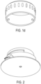
Figure 1d is a bottom perspective view of the dosing dial/button. -
Figure 2 is a bottom perspective view of the dosing/control collar shown inFigure 1a . -
Figure 3 is a cross-sectional view of the dosing/control collar shown inFigure 1a . -
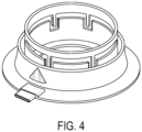
Figure 4 is a perspective view of a dosing/control collar according to a further alternative embodiment of the invention. -
Figure 5a is a perspective view of an assembled adjustable fluid dosing dispenser according to an embodiment of the invention in a closed/locked position. -
Figure 5b is an alternate rendition of the embodiment shown inFigure 5a . -
Figure 6a is a perspective view of an adjustable fluid dosing dispenser according to another embodiment. -
Figure 6b is a side elevation view of the adjustable fluid dosing dispenser according to the embodiment ofFigure 6a . -
Figure 6c is a side cross-sectional view of the adjustable fluid dosing dispenser according to the embodiments ofFigures 6a and 6b . -
Figure 7a is a perspective view of an adjustable fluid dosing dispenser according to an embodiment of the invention proximate to a matching opening in a flexible fluid container. -
Figure 7b is an alternate rendition of the embodiment shown inFigure 7a . -
Figure 8a is a perspective view of an adjustable fluid dosing dispenser attached to the surface of a flexible fluid container according to an embodiment of the invention. -
Figure 8b is an alternate rendition of the embodiment shown inFigure 8a . - The present invention is a device for dispensing fluid from a pouch, the device capable of being set to different discrete and repeatable/equal dispensing amounts, depending on the amount of fluid required to be dispensed by the user for various applications and uses. The device may also be set to an "off" or "closed" position to prevent accidental dispensing of fluid when not in use. The device is preferably configured to be affixed to the outer surface of a fluid container, which fluid container is preferably a flexible bag or pouch. According to various embodiments, at least one surface of the fluid container or a sufficient portion of the fluid container is flexible to allow the container to collapse as fluid is withdrawn therefrom. In the case that the entire fluid container is not made of flexible material, the dispensing device is preferably attached to portion of the container that is flexible and which is collapsible as fluid is dispensed from the container.
- The device also includes one or more sensors configured to record, store and/or transmit one or more physical properties of the device, particularly when the dispensing device is actuated in order to dispense fluid and/or when the device is adjusted to a particular dose.
-
Figures 1a-1c show an embodiment of the device including a dosing/control collar, a flexible dosing dome, and a combined dose setting dial and dose delivery button. The flexible dosing dome and the dosing/control collar, when assembled, form the pump or dosing chamber. The dosing/control collar is preferably cylindrical in shape with concentric inner and outer annular shafts/columns rising from a common base and defining a narrow channel between them. The exterior of the outer annular shaft may feature a flange that extends away from the center of the shaft. The interior shaft also features a plurality of horizontal and vertical dosing and rotation channels or slots that receive and interact with corresponding nubs on the outside surface of the dose dial/button. According to an alternative embodiment, the dosing and rotation channels may be on the shaft of the dose dial/button and the nubs may be on the outside surface of the inner annular shaft. The horizontal slots are the rotation slots and may have a plurality of détente locations so that the user can tactically feel the progress of the dial as it is being rotated. The vertical channels are the dosing slots and have differing depths (measured from the horizontal slot to the bottom of the vertical slot) which correspond to different dispensing amounts. According to a preferred embodiment, each vertical slot in the inner annular shaft is paired with a second vertical slot of the same depth, spaced apart on the inner annular shaft, and each nub on the dose dial button is paired with a second nub spaced apart on the dose/dial button at a location that corresponds to the location of the second vertical shaft. When the dial/button is rotated so that a nub on the exterior of the dial/button lines up with a vertical slot, the button can be depressed to dispense fluid. The limit of depression limits the amount dispensed, and the depth of the vertical slot limits how far the button can be depressed because when the nub hits the bottom of the vertical slot, the dial/button is prevented from being depressed any further without breaking the nub, the slot/channel, or both. - According to one embodiment, there is at least one vertical slot or set of vertical slots for a "Full" dose, and there is at least one second vertical slot or set of vertical slots for a "Half" or "Partial" does. According to other embodiments, there may be a third and fourth vertical slots or sets of vertical slots for other fractional doses, for example, ¾ dose, 2/3 dose, 1/3 dose and ¼ dose.
- The dosing control collar also features a through-opening in the bottom surface to accommodate the entry of fluid, fluid inlet valve, represented in
Figure 3 as a flexible flap that is configured to lie over the through-opening, a fluid outlet on the outside surface of the dosing control collar, and a fluid delivery channel between said fluid inlet and said fluid outlet. - According to a further alternative embodiment shown in
Figure 4 , the dosing control collar may have separate dosing slots and return slots. According to this embodiment, the dosing slots may have downward facing teeth or prongs which prevent the nubs from traveling upwards, thus requiring that the dial/button be fully depressed before it returns to the set position. Since the nubs cannot travel upwards in the dosing slots, separate return slots are provided adjacent the dosing slots, connected by a horizontal slot. The return slots preferably have upward facing teeth or prongs to prevent the nubs from traveling downward while in the return slots. - The dose setting dial/dose delivery button is preferably manufactured of relatively rigid plastic having a rigid bottom portion that snaps into the channel formed between the inner and outer annular shafts of the base (dosing/control collar).
- The dose setting dial/dose delivery button and the dosing/control collar are preferably made of a rigid plastic material. Nubs molded to or otherwise formed on the interior surface of the dial/button rest inside the slots formed in the interior shaft. When a user presses the dial/button, the dial/button forces the flexible dosing dome downward to evacuate the interior volume of the dome via the fluid outlet; when the dial/button is released, the flexible dosing dome returns to its original shape, forcing the dial/button upward, and drawing fluid into the interior of the dome under vacuum action.
- The flexible dosing dome is preferably made of shape memory elastomeric material that returns to its original shape after deformation.
-
Figures 5a and 5b show these three parts assembled into an adjustable fluid dispensing device according to the invention in which the flexible dosing dome is sealed to the base inside the interior column of the dosing/control collar and the bottom portion of the dose setting dial/dose delivery button is snapped over the flexible dosing dome into the channel between the inner and outer shafts. The upper portion of the dial/button projects above the top of the dosing/control collar. According to a preferred embodiment, the perimeter of the upper portion of the dial/button has molded or printed indicia such as "Open" "Closed" and "FULL" and "HALF" to indicate the rotary position of the dial that corresponds to various functions or dispensing amounts. Each of these indicia corresponds to a nub/slot combination that permits no depression, full depression, half depression, or other partial depression to dispense a corresponding amount of fluid. Likewise, the outside surface of the outer shaft of the collar preferably has printed or molded or other indicia indicating the location on the collar that must be lined up with the appropriate indicia on the dial/button in order to achieve the desired function. In the configuration shown inFigures 5a and 5b , the dial/button is in the fully depressed position, and rotated counterclockwise so that the nubs on the inside surface of the dial/button are in the bottom horizontal slot, locking the dial/button into a closed position. According to a preferred embodiment, the bottom horizontal slot has a slight downward slant before becoming horizontal to draw the dial/button down slightly as it is rotated into the closed position, seeFigure 1c , causing the bottom surface of the dial button to bear down on the fluid delivery channel, pinching it shut. As shown inFigures 5a and 5b , the indicia on the collar lines up with a "<Open" indicia on the button, showing that in order to dispense fluid, the dial/button must be rotated clockwise until the nubs line up with the "FULL" vertical slot. If the user wishes to dispense only a half dose, the dial/button must be rotated clockwise again until the nubs line up with the correspondingly shorter/shallower vertical channel/slot. -
Figures 6a, 6b and6c show an alternative design of an adjustable fluid dispensing device according to the invention. Instead of the nub and slot interaction of the device shown inFigures 1a-1d ,2 ,4 ,5a and 5b , the embodiment ofFigures 6a, 6b and6c contains a central screw that can be turned by the top dial portion for a continuous dose adjustment device. As the screw is turned, the maximum depression of the button of increased or decreased as the screw moves the button toward or away from the dosing control collar. As with the embodiment ofFigures 1a-1d ,2 ,4 ,5a and 5b , a sensor or other smart chip may be arranged to detect the rotation and hence the dosage amount. -
Figures 7a and 7b show the adjustable metering device of the invention about to be connected to a flexible fluid container, preferably a bag or pouch. According to a preferred embodiment, the fluid container is collapsible as fluid is dispensed therefrom and preferably contains no air. According to one embodiment, the bottom of the adjustable metering device has an adhesive that makes a secure and air-tight connection to the fluid container. According to a further embodiment, the adhesive may be covered prior to use with a thin pull-away film to protect and preserve the adhesive until it is time to connect the device to the fluid container. According to various alternative embodiments, the bottom of the adjustable metering device may be heat welded to the fluid container, sonic welded to the fluid container or sealed to the fluid container in any other known method. According to a further embodiment, the fluid container may have a reinforced region and/or treated surface that corresponds to the shape and size of the device to facilitate strong and secure connection and prevent container breaking or tearing should a force or load be applied to the device after it has been attached to the fluid container. -
Figures 8a and 8b show an adjustable metering device of the invention connected to a flexible fluid container. The device can be operated to dispense fluid no matter the orientation of the device in space, as it is agnostic to gravity or other forces except for the depression of the dial/button. - Application will represent educational materials on the fluid being dispensed.
- Compliance measured by actual pressure on the button and number of times pushed. Time and date captured. Ability to reorder when pouch is close to deletion.
- Smartphone application automatically track the dose size and time using either the mechanical or sensor technologies.
- Data can be shared with physician, pharmacy, retailers, manufacturers or others, as permissible by users, requiring compliance, monitoring and reordering capabilities. Senor and app technologies allow for identification of reorder options using GPS technologies or online ordering applications.
- According to an embodiment the fluid can be of any viscosity.
- According to another embodiment RFID, sensor stickers, Bluetooth and other sensor technologies are used.
- The user will download the app. The app will pick up the sensor signal from the sensor technology and prompt for educational and compliance engagement.
- The app will automatically capture dose, time of dose, prompt for next dose, and alert when near depletion, requiring a reorder.
- This is doable from day one using readily available sensor technologies.
- The app will alert when the dose is due.
- Pressure sensor in the "button" sends a signal that the fluid was dispensed and how much. 1TOUCH dispensing technology indicates dosage.
- Patient can provide permissions through the app to share with physician, pharmacy, retailers, manufacturers or others requiring compliance, monitoring and reordering capabilities.
- Sensor technologies provide automatic tracking to ensure ease of use. GPS enables realtime capabilities for reorder and retail oportunties.
Claims (14)
- An apparatus for dispensing and monitoring fluid dispensed comprising:a flexible and collapsible fluid container;a fluid dispenser pump connected to said flexible and collapsible fluid container configured to draw fluid from said flexible and collapsible fluid container into said fluid dispenser pump and to dispense fluid through a fluid delivery channel to an exit port upon actuation of said pump;the dispenser pump having an actuator comprising a dose delivery button connected to said flexible and collapsible fluid container via a dose button base which, upon depression by a user, actuates the fluid dispenser pump to dispense a dose of fluid;a sensor located in said apparatus and configured to measure a time of day and a physical property change upon actuation of the dose delivery button of said fluid dispenser pump by a user, the physical property change comprising information on the amount of fluid dispensed; anda wireless transmission module in communication with said sensor configured to communicate said physical property to a remote device upon depression of the dose delivery button of said fluid dispenser pump by the user, andwherein user dose compliance is measured by actual pressure on the button in order to dispense fluid and number of times pushed.
- An apparatus according to claim 1, wherein said physical property is selected from the group consisting of fluid pressure inside said fluid dispenser pump, volume of fluid flowing through said exit port.
- An apparatus according to claim 1 or 2, wherein said remote device is a computer server.
- An apparatus according to any one of the preceding claims, wherein said remote device is a mobile device.
- An apparatus according to any one of the preceding claims, wherein said flexible and collapsible fluid container includes a computer readable identification code printed thereon or attached thereto.
- An apparatus according to claim 5, wherein said computer readable identification code is configured to cause product information relating to said fluid to be displayed on a user's mobile device when said user's mobile device is used to read said computer readable identification code.
- An apparatus according to any one of the preceding claims, wherein the sensor is located inside or beneath the dose delivery button, or in a fluid delivery channel.
- An apparatus according to any one of the preceding claims, wherein the dose delivery button is adjustable by the user to adjust the amount of the dose of the fluid dispensed upon actuation by the user.
- An apparatus according to claim 8, including a sensor to determine adjustment state of the actuator.
- An apparatus according to any one of the preceding claims, wherein the flexible and collapsible fluid container includes a computer readable identification code, and the computer readable identification code is configured to cause product information relating to the fluid to be displayed on the remote device.
- A method of dispensing and monitoring fluid dispensed from an apparatus comprising:providing a flexible and collapsible fluid container; a fluid dispenser pump connected to the flexible and collapsible fluid container configured to draw fluid from the flexible and collapsible fluid container into the fluid dispenser pump and to dispense fluid through a fluid delivery channel to an exit port upon actuation of the pump, the dispenser pump having an actuator comprising a dose delivery button connected to said flexible and collapsible fluid container via a dose button base which, upon depression by a user, actuates the fluid dispenser pump to dispense a dose of fluid; a sensor located in the apparatus and configured to measure a physical property change upon actuation of the dose delivery button of the fluid dispenser pump by a user, the physical property change comprising information on the amount of fluid dispensed; and a wireless transmission module in communication with the sensor configured to communicate the physical property change to a remote device upon depression of the dose delivery button of said fluid dispenser pump by the user, and wherein user dose compliance is measured by actual pressure on the button in order to dispense fluid and number of times pushed;depressing, by the user, the dose delivery button to actuate the fluid dispenser pump to dispense fluid from the flexible and collapsible fluid container through the exit port;upon depression by the user of the dose delivery button, sensing by the sensor information on the amount of fluid dispensed from the exit port; andwirelessly transmitting information on the amount of fluid dispensed from the sensor to a remote device.
- A method according to claim 11, wherein the sensor is located inside or beneath the dose delivery button, or in the fluid delivery channel.
- A method according to claim 11, wherein the actuator is adjustable by the user to adjust the amount of the dose of the fluid dispensed upon actuation by the user, and including a sensor to determine adjustment state of the actuator, and further including wirelessly transmitting information on the adjustment state of the actuator to the remote device.
- A method according to claim 11, wherein the flexible and collapsible fluid container includes a computer readable identification code including product information relating to the fluid, and further including wirelessly transmitting the computer readable identification code to cause product information relating to the fluid to be displayed on the remote device.
Applications Claiming Priority (2)
| Application Number | Priority Date | Filing Date | Title |
|---|---|---|---|
| US201862695306P | 2018-07-09 | 2018-07-09 | |
| PCT/US2019/041090 WO2020014288A1 (en) | 2018-07-09 | 2019-07-09 | Fluid dispensing apparatus |
Publications (3)
| Publication Number | Publication Date |
|---|---|
| EP3820787A1 EP3820787A1 (en) | 2021-05-19 |
| EP3820787A4 EP3820787A4 (en) | 2022-04-06 |
| EP3820787B1 true EP3820787B1 (en) | 2025-05-28 |
Family
ID=74418897
Family Applications (1)
| Application Number | Title | Priority Date | Filing Date |
|---|---|---|---|
| EP19833812.1A Active EP3820787B1 (en) | 2018-07-09 | 2019-07-09 | Fluid dispensing apparatus |
Country Status (2)
| Country | Link |
|---|---|
| EP (1) | EP3820787B1 (en) |
| CN (1) | CN112292333A (en) |
Family Cites Families (9)
| Publication number | Priority date | Publication date | Assignee | Title |
|---|---|---|---|---|
| US6053888A (en) * | 1998-08-05 | 2000-04-25 | Kong; Carl Cheung Tung | Variable volume bottle and related medical fluid infusion system |
| US6790198B1 (en) * | 1999-12-01 | 2004-09-14 | B-Braun Medical, Inc. | Patient medication IV delivery pump with wireless communication to a hospital information management system |
| CN101321684A (en) * | 2005-10-21 | 2008-12-10 | Ch&I技术公司 | Integrated Material Delivery and Distribution System |
| EP2554488B1 (en) * | 2009-01-09 | 2014-05-21 | Liqui-Box Corporation | Collapsible container with a fitment and method of dispensing materials using said container |
| US7982612B2 (en) * | 2009-02-20 | 2011-07-19 | Mckesson Automation Inc. | Methods, apparatuses, and computer program products for monitoring a volume of fluid in a flexible fluid bag |
| EP2724739B1 (en) * | 2009-07-30 | 2015-07-01 | Tandem Diabetes Care, Inc. | Portable infusion pump system |
| WO2014152704A1 (en) * | 2013-03-15 | 2014-09-25 | Becton, Dickinson And Company | Smart adapter for infusion devices |
| US9606037B2 (en) * | 2015-01-23 | 2017-03-28 | Aesynt Incorporated | Fluid container with fluid identification sensor and method |
| BR112018072139A2 (en) * | 2016-04-27 | 2019-04-16 | Innovationcooperative3D, Llc | adjustable dosing fluid dispenser for flexible fluid packages |
-
2019
- 2019-07-09 CN CN201980041498.7A patent/CN112292333A/en active Pending
- 2019-07-09 EP EP19833812.1A patent/EP3820787B1/en active Active
Also Published As
| Publication number | Publication date |
|---|---|
| EP3820787A1 (en) | 2021-05-19 |
| CN112292333A (en) | 2021-01-29 |
| EP3820787A4 (en) | 2022-04-06 |
Similar Documents
| Publication | Publication Date | Title |
|---|---|---|
| JP4615926B2 (en) | Wireless automatic recognition device (RFID) and automatic medicine recognition system | |
| US11918779B2 (en) | Smart 1TOUCH | |
| CN101912641B (en) | Drug delivery pen with event notification means | |
| EP2123318B1 (en) | Dose dispensing system and apparatus | |
| US12322487B1 (en) | Biometrically controlled handheld oral medication dispensing device | |
| US11192705B2 (en) | Smart 1 touch | |
| EP2906175B1 (en) | Drug delivery capsules with external intelligence | |
| US20230338975A1 (en) | Fluid dispensing apparatus | |
| CN104582596A (en) | Integrated injection system and communication device | |
| AU2022203979A1 (en) | Adjustable dosing fluid dispenser for flexible fluid packages | |
| US20250316357A1 (en) | Caregiver system and method for interfacing with and controlling a medication dispensing device | |
| US20170024542A1 (en) | Logging system and a method of registering data for enabling monitoring of intake of a product by a user according to an intake plan | |
| US12280014B1 (en) | Keyed medication cartridge for use in a handheld oral medication dispensing device | |
| US20260066077A1 (en) | Patient system and method for interfacing with and controlling a medication dispensing device | |
| CN108557258B (en) | Smart containers and their applications | |
| EP3820787A1 (en) | Fluid dispensing apparatus | |
| WO2023107456A1 (en) | Fluid dispensing apparatus | |
| EP2502852A1 (en) | Dispensing device | |
| JP4405737B2 (en) | Syringe pump | |
| US12478558B2 (en) | Physician system and method for interfacing with and controlling a medication dispensing device | |
| US20250288494A1 (en) | Rechargeable handheld oral medication dispensing device | |
| US20250288498A1 (en) | Wirelessly controlled handheld oral medication dispensing device | |
| US20250281702A1 (en) | Handheld oral medication dispensing device with activator mechanism |
Legal Events
| Date | Code | Title | Description |
|---|---|---|---|
| STAA | Information on the status of an ep patent application or granted ep patent |
Free format text: STATUS: THE INTERNATIONAL PUBLICATION HAS BEEN MADE |
|
| PUAI | Public reference made under article 153(3) epc to a published international application that has entered the european phase |
Free format text: ORIGINAL CODE: 0009012 |
|
| STAA | Information on the status of an ep patent application or granted ep patent |
Free format text: STATUS: REQUEST FOR EXAMINATION WAS MADE |
|
| 17P | Request for examination filed |
Effective date: 20210205 |
|
| AK | Designated contracting states |
Kind code of ref document: A1 Designated state(s): AL AT BE BG CH CY CZ DE DK EE ES FI FR GB GR HR HU IE IS IT LI LT LU LV MC MK MT NL NO PL PT RO RS SE SI SK SM TR |
|
| DAV | Request for validation of the european patent (deleted) | ||
| DAX | Request for extension of the european patent (deleted) | ||
| A4 | Supplementary search report drawn up and despatched |
Effective date: 20220309 |
|
| RIC1 | Information provided on ipc code assigned before grant |
Ipc: B65D 83/00 20060101ALI20220302BHEP Ipc: B05B 11/00 20060101AFI20220302BHEP |
|
| REG | Reference to a national code |
Ref country code: DE Ref legal event code: R079 Free format text: PREVIOUS MAIN CLASS: B65D0083000000 Ipc: B05B0011000000 Ref country code: DE Ref legal event code: R079 Ref document number: 602019070596 Country of ref document: DE Free format text: PREVIOUS MAIN CLASS: B65D0083000000 Ipc: B05B0011000000 |
|
| RIC1 | Information provided on ipc code assigned before grant |
Ipc: B65D 83/00 20060101ALI20240711BHEP Ipc: B05B 11/10 20230101ALI20240711BHEP Ipc: B05B 11/00 20060101AFI20240711BHEP |
|
| GRAP | Despatch of communication of intention to grant a patent |
Free format text: ORIGINAL CODE: EPIDOSNIGR1 |
|
| STAA | Information on the status of an ep patent application or granted ep patent |
Free format text: STATUS: GRANT OF PATENT IS INTENDED |
|
| INTG | Intention to grant announced |
Effective date: 20240819 |
|
| GRAJ | Information related to disapproval of communication of intention to grant by the applicant or resumption of examination proceedings by the epo deleted |
Free format text: ORIGINAL CODE: EPIDOSDIGR1 |
|
| STAA | Information on the status of an ep patent application or granted ep patent |
Free format text: STATUS: REQUEST FOR EXAMINATION WAS MADE |
|
| GRAP | Despatch of communication of intention to grant a patent |
Free format text: ORIGINAL CODE: EPIDOSNIGR1 |
|
| STAA | Information on the status of an ep patent application or granted ep patent |
Free format text: STATUS: GRANT OF PATENT IS INTENDED |
|
| INTC | Intention to grant announced (deleted) | ||
| INTG | Intention to grant announced |
Effective date: 20250115 |
|
| GRAS | Grant fee paid |
Free format text: ORIGINAL CODE: EPIDOSNIGR3 |
|
| GRAA | (expected) grant |
Free format text: ORIGINAL CODE: 0009210 |
|
| STAA | Information on the status of an ep patent application or granted ep patent |
Free format text: STATUS: THE PATENT HAS BEEN GRANTED |
|
| AK | Designated contracting states |
Kind code of ref document: B1 Designated state(s): AL AT BE BG CH CY CZ DE DK EE ES FI FR GB GR HR HU IE IS IT LI LT LU LV MC MK MT NL NO PL PT RO RS SE SI SK SM TR |
|
| REG | Reference to a national code |
Ref country code: GB Ref legal event code: FG4D |
|
| REG | Reference to a national code |
Ref country code: CH Ref legal event code: EP |
|
| REG | Reference to a national code |
Ref country code: DE Ref legal event code: R096 Ref document number: 602019070596 Country of ref document: DE |
|
| REG | Reference to a national code |
Ref country code: IE Ref legal event code: FG4D |
|
| REG | Reference to a national code |
Ref country code: NL Ref legal event code: MP Effective date: 20250528 |
|
| PG25 | Lapsed in a contracting state [announced via postgrant information from national office to epo] |
Ref country code: FI Free format text: LAPSE BECAUSE OF FAILURE TO SUBMIT A TRANSLATION OF THE DESCRIPTION OR TO PAY THE FEE WITHIN THE PRESCRIBED TIME-LIMIT Effective date: 20250528 Ref country code: ES Free format text: LAPSE BECAUSE OF FAILURE TO SUBMIT A TRANSLATION OF THE DESCRIPTION OR TO PAY THE FEE WITHIN THE PRESCRIBED TIME-LIMIT Effective date: 20250528 |
|
| REG | Reference to a national code |
Ref country code: LT Ref legal event code: MG9D |
|
| PG25 | Lapsed in a contracting state [announced via postgrant information from national office to epo] |
Ref country code: NO Free format text: LAPSE BECAUSE OF FAILURE TO SUBMIT A TRANSLATION OF THE DESCRIPTION OR TO PAY THE FEE WITHIN THE PRESCRIBED TIME-LIMIT Effective date: 20250828 Ref country code: GR Free format text: LAPSE BECAUSE OF FAILURE TO SUBMIT A TRANSLATION OF THE DESCRIPTION OR TO PAY THE FEE WITHIN THE PRESCRIBED TIME-LIMIT Effective date: 20250829 |
|
| PG25 | Lapsed in a contracting state [announced via postgrant information from national office to epo] |
Ref country code: PL Free format text: LAPSE BECAUSE OF FAILURE TO SUBMIT A TRANSLATION OF THE DESCRIPTION OR TO PAY THE FEE WITHIN THE PRESCRIBED TIME-LIMIT Effective date: 20250528 Ref country code: NL Free format text: LAPSE BECAUSE OF FAILURE TO SUBMIT A TRANSLATION OF THE DESCRIPTION OR TO PAY THE FEE WITHIN THE PRESCRIBED TIME-LIMIT Effective date: 20250528 |
|
| PG25 | Lapsed in a contracting state [announced via postgrant information from national office to epo] |
Ref country code: BG Free format text: LAPSE BECAUSE OF FAILURE TO SUBMIT A TRANSLATION OF THE DESCRIPTION OR TO PAY THE FEE WITHIN THE PRESCRIBED TIME-LIMIT Effective date: 20250528 |
|
| PG25 | Lapsed in a contracting state [announced via postgrant information from national office to epo] |
Ref country code: HR Free format text: LAPSE BECAUSE OF FAILURE TO SUBMIT A TRANSLATION OF THE DESCRIPTION OR TO PAY THE FEE WITHIN THE PRESCRIBED TIME-LIMIT Effective date: 20250528 |
|
| PG25 | Lapsed in a contracting state [announced via postgrant information from national office to epo] |
Ref country code: RS Free format text: LAPSE BECAUSE OF FAILURE TO SUBMIT A TRANSLATION OF THE DESCRIPTION OR TO PAY THE FEE WITHIN THE PRESCRIBED TIME-LIMIT Effective date: 20250828 |
|
| PG25 | Lapsed in a contracting state [announced via postgrant information from national office to epo] |
Ref country code: IS Free format text: LAPSE BECAUSE OF FAILURE TO SUBMIT A TRANSLATION OF THE DESCRIPTION OR TO PAY THE FEE WITHIN THE PRESCRIBED TIME-LIMIT Effective date: 20250928 |
|
| PG25 | Lapsed in a contracting state [announced via postgrant information from national office to epo] |
Ref country code: LV Free format text: LAPSE BECAUSE OF FAILURE TO SUBMIT A TRANSLATION OF THE DESCRIPTION OR TO PAY THE FEE WITHIN THE PRESCRIBED TIME-LIMIT Effective date: 20250528 |
|
| REG | Reference to a national code |
Ref country code: AT Ref legal event code: MK05 Ref document number: 1798347 Country of ref document: AT Kind code of ref document: T Effective date: 20250528 |
|
| PGFP | Annual fee paid to national office [announced via postgrant information from national office to epo] |
Ref country code: GB Payment date: 20251211 Year of fee payment: 7 |
|
| PG25 | Lapsed in a contracting state [announced via postgrant information from national office to epo] |
Ref country code: AT Free format text: LAPSE BECAUSE OF FAILURE TO SUBMIT A TRANSLATION OF THE DESCRIPTION OR TO PAY THE FEE WITHIN THE PRESCRIBED TIME-LIMIT Effective date: 20250528 Ref country code: SM Free format text: LAPSE BECAUSE OF FAILURE TO SUBMIT A TRANSLATION OF THE DESCRIPTION OR TO PAY THE FEE WITHIN THE PRESCRIBED TIME-LIMIT Effective date: 20250528 Ref country code: DK Free format text: LAPSE BECAUSE OF FAILURE TO SUBMIT A TRANSLATION OF THE DESCRIPTION OR TO PAY THE FEE WITHIN THE PRESCRIBED TIME-LIMIT Effective date: 20250528 |
|
| PG25 | Lapsed in a contracting state [announced via postgrant information from national office to epo] |
Ref country code: CZ Free format text: LAPSE BECAUSE OF FAILURE TO SUBMIT A TRANSLATION OF THE DESCRIPTION OR TO PAY THE FEE WITHIN THE PRESCRIBED TIME-LIMIT Effective date: 20250528 |
|
| PG25 | Lapsed in a contracting state [announced via postgrant information from national office to epo] |
Ref country code: EE Free format text: LAPSE BECAUSE OF FAILURE TO SUBMIT A TRANSLATION OF THE DESCRIPTION OR TO PAY THE FEE WITHIN THE PRESCRIBED TIME-LIMIT Effective date: 20250528 |
|
| PG25 | Lapsed in a contracting state [announced via postgrant information from national office to epo] |
Ref country code: RO Free format text: LAPSE BECAUSE OF FAILURE TO SUBMIT A TRANSLATION OF THE DESCRIPTION OR TO PAY THE FEE WITHIN THE PRESCRIBED TIME-LIMIT Effective date: 20250528 Ref country code: SK Free format text: LAPSE BECAUSE OF FAILURE TO SUBMIT A TRANSLATION OF THE DESCRIPTION OR TO PAY THE FEE WITHIN THE PRESCRIBED TIME-LIMIT Effective date: 20250528 |
|
| PG25 | Lapsed in a contracting state [announced via postgrant information from national office to epo] |
Ref country code: IT Free format text: LAPSE BECAUSE OF FAILURE TO SUBMIT A TRANSLATION OF THE DESCRIPTION OR TO PAY THE FEE WITHIN THE PRESCRIBED TIME-LIMIT Effective date: 20250528 |
|
| REG | Reference to a national code |
Ref country code: DE Ref legal event code: R119 Ref document number: 602019070596 Country of ref document: DE |
|
| REG | Reference to a national code |
Ref country code: CH Ref legal event code: H13 Free format text: ST27 STATUS EVENT CODE: U-0-0-H10-H13 (AS PROVIDED BY THE NATIONAL OFFICE) Effective date: 20260224 |
|
| PG25 | Lapsed in a contracting state [announced via postgrant information from national office to epo] |
Ref country code: LU Free format text: LAPSE BECAUSE OF NON-PAYMENT OF DUE FEES Effective date: 20250709 |
|
| REG | Reference to a national code |
Ref country code: BE Ref legal event code: MM Effective date: 20250731 |
|
| PLBE | No opposition filed within time limit |
Free format text: ORIGINAL CODE: 0009261 |
|
| STAA | Information on the status of an ep patent application or granted ep patent |
Free format text: STATUS: NO OPPOSITION FILED WITHIN TIME LIMIT |
|
| REG | Reference to a national code |
Ref country code: CH Ref legal event code: L10 Free format text: ST27 STATUS EVENT CODE: U-0-0-L10-L00 (AS PROVIDED BY THE NATIONAL OFFICE) Effective date: 20260409 |
|
| PG25 | Lapsed in a contracting state [announced via postgrant information from national office to epo] |
Ref country code: DE Free format text: LAPSE BECAUSE OF NON-PAYMENT OF DUE FEES Effective date: 20260203 |
|
| PG25 | Lapsed in a contracting state [announced via postgrant information from national office to epo] |
Ref country code: BE Free format text: LAPSE BECAUSE OF NON-PAYMENT OF DUE FEES Effective date: 20250731 |
|
| PG25 | Lapsed in a contracting state [announced via postgrant information from national office to epo] |
Ref country code: FR Free format text: LAPSE BECAUSE OF NON-PAYMENT OF DUE FEES Effective date: 20250728 |
|
| PG25 | Lapsed in a contracting state [announced via postgrant information from national office to epo] |
Ref country code: CH Free format text: LAPSE BECAUSE OF NON-PAYMENT OF DUE FEES Effective date: 20250731 |
|
| 26N | No opposition filed |
Effective date: 20260303 |