EP3820236B1 - Verbesserung der direktzugriffskanalgelegenheit und ss/pbch-blockzuordnung - Google Patents
Verbesserung der direktzugriffskanalgelegenheit und ss/pbch-blockzuordnung Download PDFInfo
- Publication number
- EP3820236B1 EP3820236B1 EP20203054.0A EP20203054A EP3820236B1 EP 3820236 B1 EP3820236 B1 EP 3820236B1 EP 20203054 A EP20203054 A EP 20203054A EP 3820236 B1 EP3820236 B1 EP 3820236B1
- Authority
- EP
- European Patent Office
- Prior art keywords
- random access
- access channel
- channel occasion
- beam index
- cycled
- Prior art date
- Legal status (The legal status is an assumption and is not a legal conclusion. Google has not performed a legal analysis and makes no representation as to the accuracy of the status listed.)
- Active
Links
- 238000000034 method Methods 0.000 claims description 22
- 238000004891 communication Methods 0.000 claims description 12
- 238000004590 computer program Methods 0.000 claims description 8
- 238000013507 mapping Methods 0.000 claims description 5
- 230000001131 transforming effect Effects 0.000 claims description 5
- 235000019527 sweetened beverage Nutrition 0.000 description 51
- 230000005540 biological transmission Effects 0.000 description 19
- 230000015654 memory Effects 0.000 description 16
- 238000013461 design Methods 0.000 description 12
- 230000006870 function Effects 0.000 description 9
- 238000013468 resource allocation Methods 0.000 description 7
- 230000011664 signaling Effects 0.000 description 7
- 238000007726 management method Methods 0.000 description 5
- 238000010586 diagram Methods 0.000 description 4
- 230000003287 optical effect Effects 0.000 description 4
- 238000005516 engineering process Methods 0.000 description 3
- 239000000835 fiber Substances 0.000 description 3
- 230000007246 mechanism Effects 0.000 description 3
- 239000004065 semiconductor Substances 0.000 description 3
- 101100411667 Arabidopsis thaliana RAN4 gene Proteins 0.000 description 2
- 101100194171 Entamoeba histolytica RACG gene Proteins 0.000 description 2
- 101150069124 RAN1 gene Proteins 0.000 description 2
- 101100355633 Salmo salar ran gene Proteins 0.000 description 2
- 230000008901 benefit Effects 0.000 description 2
- 230000008878 coupling Effects 0.000 description 2
- 238000010168 coupling process Methods 0.000 description 2
- 238000005859 coupling reaction Methods 0.000 description 2
- 125000004122 cyclic group Chemical group 0.000 description 2
- 230000001351 cycling effect Effects 0.000 description 2
- 238000011156 evaluation Methods 0.000 description 2
- 230000007774 longterm Effects 0.000 description 2
- 230000010363 phase shift Effects 0.000 description 2
- 230000008569 process Effects 0.000 description 2
- 238000001228 spectrum Methods 0.000 description 2
- 230000009466 transformation Effects 0.000 description 2
- 101150096310 SIB1 gene Proteins 0.000 description 1
- 238000013459 approach Methods 0.000 description 1
- 238000013500 data storage Methods 0.000 description 1
- 230000000694 effects Effects 0.000 description 1
- 238000005259 measurement Methods 0.000 description 1
- 238000012544 monitoring process Methods 0.000 description 1
- 238000005457 optimization Methods 0.000 description 1
- 239000000758 substrate Substances 0.000 description 1
Images


Classifications
-
- H—ELECTRICITY
- H04—ELECTRIC COMMUNICATION TECHNIQUE
- H04W—WIRELESS COMMUNICATION NETWORKS
- H04W74/00—Wireless channel access
- H04W74/08—Non-scheduled access, e.g. ALOHA
- H04W74/0833—Random access procedures, e.g. with 4-step access
-
- H—ELECTRICITY
- H04—ELECTRIC COMMUNICATION TECHNIQUE
- H04W—WIRELESS COMMUNICATION NETWORKS
- H04W72/00—Local resource management
- H04W72/04—Wireless resource allocation
- H04W72/044—Wireless resource allocation based on the type of the allocated resource
- H04W72/046—Wireless resource allocation based on the type of the allocated resource the resource being in the space domain, e.g. beams
-
- H—ELECTRICITY
- H04—ELECTRIC COMMUNICATION TECHNIQUE
- H04B—TRANSMISSION
- H04B7/00—Radio transmission systems, i.e. using radiation field
- H04B7/02—Diversity systems; Multi-antenna system, i.e. transmission or reception using multiple antennas
- H04B7/04—Diversity systems; Multi-antenna system, i.e. transmission or reception using multiple antennas using two or more spaced independent antennas
- H04B7/06—Diversity systems; Multi-antenna system, i.e. transmission or reception using multiple antennas using two or more spaced independent antennas at the transmitting station
- H04B7/0686—Hybrid systems, i.e. switching and simultaneous transmission
- H04B7/0695—Hybrid systems, i.e. switching and simultaneous transmission using beam selection
-
- H—ELECTRICITY
- H04—ELECTRIC COMMUNICATION TECHNIQUE
- H04L—TRANSMISSION OF DIGITAL INFORMATION, e.g. TELEGRAPHIC COMMUNICATION
- H04L5/00—Arrangements affording multiple use of the transmission path
- H04L5/0001—Arrangements for dividing the transmission path
- H04L5/0014—Three-dimensional division
- H04L5/0023—Time-frequency-space
-
- H—ELECTRICITY
- H04—ELECTRIC COMMUNICATION TECHNIQUE
- H04L—TRANSMISSION OF DIGITAL INFORMATION, e.g. TELEGRAPHIC COMMUNICATION
- H04L5/00—Arrangements affording multiple use of the transmission path
- H04L5/003—Arrangements for allocating sub-channels of the transmission path
- H04L5/0048—Allocation of pilot signals, i.e. of signals known to the receiver
-
- H—ELECTRICITY
- H04—ELECTRIC COMMUNICATION TECHNIQUE
- H04L—TRANSMISSION OF DIGITAL INFORMATION, e.g. TELEGRAPHIC COMMUNICATION
- H04L5/00—Arrangements affording multiple use of the transmission path
- H04L5/0091—Signaling for the administration of the divided path
- H04L5/0094—Indication of how sub-channels of the path are allocated
-
- H—ELECTRICITY
- H04—ELECTRIC COMMUNICATION TECHNIQUE
- H04W—WIRELESS COMMUNICATION NETWORKS
- H04W74/00—Wireless channel access
- H04W74/002—Transmission of channel access control information
-
- H—ELECTRICITY
- H04—ELECTRIC COMMUNICATION TECHNIQUE
- H04W—WIRELESS COMMUNICATION NETWORKS
- H04W74/00—Wireless channel access
- H04W74/002—Transmission of channel access control information
- H04W74/006—Transmission of channel access control information in the downlink, i.e. towards the terminal
Definitions
- the teachings in accordance with the exemplary embodiments of this invention relate generally to a Random Access Channel (RACH) resource allocation and, more specifically, relate to a Random Access Channel (RACH) resource allocation for a repetition transmission mode and association to Synchronization Signal and PBCH blocks (SS/PBCH).
- RACH Random Access Channel
- SS/PBCH Synchronization Signal and PBCH blocks
- Random access in wireless systems are used to initiate and facilitate communication between user equipment (UE) and a network.
- the UE and the network which may include a base station (BS) interact for the random access, and to provide wireless communication services for the UE.
- BS base station
- Such random access procedures enables a UE to extract timing and frequency and/or phase information for timing and frequency synchronization.
- Example embodiments of the invention at least work to improve such random access procedures in radio technologies including new radio (NR) radio technologies.
- NR new radio
- ERICSSON "Enhancements to initial access procedure", 3GPP DRAFT; R1-1907455, 13 May 2019 (2019-05-13), XP051728886 , discusses about procedures for initial access, RRM measurements and radio link monitoring. For instance, reading of RMSI (including RACH configuration) and support signaling of Q in SIB1 is disclosed therein.
- Example embodiments of this invention relate to a Random Access Channel (RACH) resource allocation for a repetition transmission mode and association to Synchronization Signal and PBCH blocks (SS/PBCH).
- RACH Random Access Channel
- SS/PBCH Synchronization Signal and PBCH blocks
- Example embodiments of the invention provide a 3GPP New Radio (NR) physical layer design. There is in accordance with example embodiments of the invention a design which may be performed by an apparatus with focus on Random Access Channel (RACH) resource allocation and association to Synchronization Signal and PBCH blocks (SS/PBCH).
- RACH Random Access Channel
- SS/PBCH Synchronization Signal and PBCH blocks
- Example embodiments of the invention relate to NR-Unlicensed operation in FR1 and FR2 and subsequent descriptions are discussed in that context but example embodiments of the invention can be used also in other use cases.
- Other use cases maybe e.g. NR operation above 52.6 GHz where first target deployment scenario would be unlicensed operation in 60 GHz unlicensed bands.
- the NR-U should specify the followings [TR38.889]: - Physical layer aspects including [RAN1]: - PRACH including possible extension of PRACH format(s) in line with agreements during the SI phase (TR 38.889, Section 7.2.1.2) to support minimum bandwidth requirement given by regulation.
- [TR38.889] Physical layer aspects including [RAN1]: - PRACH including possible extension of PRACH format(s) in line with agreements during the SI phase (TR 38.889, Section 7.2.1.2) to support minimum bandwidth requirement given by regulation.
- RAN1 should decide whether 60 kHz subcarrier spacing for PRACH is supported, based on a unified design with 15 kHz and 30 kHz PRACH for meeting occupied channel bandwidth (OCB) requirements.
- OCB occupied channel bandwidth
- a relevant scope agreed for this may include the following:
- a status in NR-U at the time of this application is that new radio (NR) length-139 short sequence is supported as well as PRACH formats A, B and C (short sequence formats) are supported.
- NR-U PRACH aims at defining PRACH preamble having bandwidth of half and full subband where subband size is 20 MHz.
- Random Access preambles are transmitted in PRACH Occasions (ROs).
- RO defines a time-frequency resource such as for a single transmission used to transmit the preamble.
- FIG. 1 illustrates alternatives for providing half and full subband PRACHs. As shown in FIG. 1 there is a 20MHz sub-band 1005 with 612 RE's using a 30 kHz SCS. Blocks 1010 of FIG. 1 show Repetition and blocks 1020 of FIG. 1 show a single long sequence.
- each RO has up to 64 preambles (total number of number of preambles including contention based and contention free preambles per RO is configurable by RRC).
- the first preamble i.e. preamble index 0, corresponds to cyclic shift 0 of the logic root sequence index given by higher layer parameter prach-RootSequenceIndex.
- Subsequent preamble indices are numbered first in increasing order of cyclic shift, and then increasing order of logical root indices, until all 64 preamble indices are obtained.
- PRACH occasions can be frequency division multiplexed in the frequency domain
- msg1-FDM M.
- a current release at the time of this application supports up to 8 Frequency Division Multiplexed (FDMed) ROs:
- FIG. 2 shows a RACH configuration with 8 ROs frequency division multiplexed (FDMed).
- FIG. 2 shows a sequence with ROs 220 where a length of time depends on format, and shows preamble 230.
- FIG. 2 also shows a gap of 5 subcarriers between sequence 235 and sequence 240 mapped in neighbouring PRACH occasions.
- UE transmits preamble in one RO (based on SSB association) while gNB detects preambles in each configured Frequency Division Multiplexed RO.
- gNB detects preambles in each configured Frequency Division Multiplexed RO.
- an association framework between PRACH ROs/preambles and the SS/PBCH blocks is defined.
- the UE Before entering the random access procedure the UE detects and measures SSBs of the selected cell (initial access), and selects the SSB that is strong enough (above certain threshold).
- the UE randomly selects a preamble in the RACH Occasion associated with the selected SS/PBCH block representing the downlink beam the UE wants to be served with.
- Each SS/PBCH block can be associated to one or up to eight consecutive ROs.
- multiple SS/PBCH blocks can be associated to one RO in which preambles are divided among the SS/PBCH blocks. In that case, SS/PBCH block cannot be associated to multiple consecutive ROs.
- the NR-U In order to support SSB burst transmission in NR-U under uncertainty due to LBT (listen-before-talk) failures (transmitting node determines that transmission resources occupied by some other transmitter by listening the resources prior intended transmission time) the NR-U considers cycling of SSBs as shown in the Table of FIG. 6A . It means that certain beam has multiple transmission possibilities within the certain time period (10 slots).
- NR-U beams are cycled to cover for LBT failure, such when gNB obtains access to channel in any of the slots of DRS window, it may cycle over all SSB/beams.
- FIG. 6A shows a Table of Relationship between slot index, SSB index for timing, PBCH DMRS sequence and beam index.
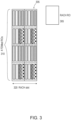
- FIG. 3 shows a configuration example of a RACH with RACH RO 305. As shown in FIG. 3 there is a sequence of 4 FDMed ROs 310 frequency division multiplexed over RACH slot 320.
- FIG. 3 One possible configuration is illustrated in FIG. 3 where we assume that there are 8 SSBs, and 4 ROs Frequency Division Multiplexed (in order to have resource allocation for either 2x half subband PRACH transmission or 1 full subband PRACH transmission) and 2 ROs TDMed in the RACH slot (Format A3 in use). Further we assume that there are 4 SSBs per RO and 16 contention based preambles per SSB (preambles per SSB are described using different patterns). The preambles associated for 8 SSBs would be mapped to ROs as in FIG. 3 .
- SSB to RACH occasion/preamble association does not take into account SSB index to beam index transformation used in NR-U.
- one problem to be solved is that how to define the association between ROs and SSBs in a way that PRACH transmission based on repetition can be performed .
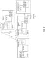
- FIG. 7 Before describing the example embodiments of the invention in detail, reference is made to FIG. 7 for illustrating a simplified block diagram of various electronic devices that are suitable for use in practicing the example embodiments of this invention.
- FIG. 7 shows a block diagram of one possible and non-limiting exemplary system in which the example embodiments of the invention may be practiced.
- a user equipment (UE) 10 is in wireless communication with a wireless network 1.
- a UE is a wireless, typically mobile device that can access a wireless network.
- the UE 10 includes one or more processors DP 10A, one or more memories MEM 10B, and one or more transceivers TRANS 10D interconnected through one or more buses.
- Each of the one or more transceivers TRANS 10D includes a receiver and a transmitter.
- the one or more buses may be address, data, or control buses, and may include any interconnection mechanism, such as a series of lines on a motherboard or integrated circuit, fiber optics or other optical communication equipment, and the like.
- the one or more transceivers TRANS 10D are connected to one or more antennas for communication 11 and 18 to gNB 12 and NN 13, respectively.
- the one or more memories MEM 10B include computer program code PROG 10C.
- the UE 10 communicates with gNB 12 and/or NN 13 via a wireless link 111.
- the gNB 12 (NR/5G Node B or possibly an evolved NB) is a base station such as a master or secondary node base station (e.g., for NR or LTE long term evolution) that communicates with devices such as NN 13 and UE 10 of FIG. 7 .
- the gNB 12 provides access to wireless devices such as the UE 10 to the wireless network 1.
- the gNB 12 includes one or more processors DP 12A, one or more memories MEM 12C, and one or more transceivers TRANS 12D interconnected through one or more buses. In accordance with the example embodiments these TRANS 12D can include X2 and/or Xn interfaces for use to perform the example embodiments of the invention.
- Each of the one or more transceivers TRANS 12D includes a receiver and a transmitter.
- the one or more transceivers TRANS 12D are connected to one or more antennas for communication over at least link 11 with the UE 10.
- the one or more memories MEM 12B and the computer program code PROG 12C are configured to cause, with the one or more processors DP 12A, the gNB 12 to perform one or more of the operations as described herein.
- the gNB 12 may communicate with another gNB or eNB, or a device such as the NN 13.
- the link 11 and or any other link may be wired or wireless or both and may implement, e.g., an X2 or Xn interface.
- the link 11 may be through other network devices such as, but not limited to an NCE/MME/SGW device such as the NCE/MME/SGW 14 of FIG. 7 .
- the NN 13 can comprise a mobility function device such as an AMF or SMF, further the NN 13 may comprise a NR/5G Node B or possibly an evolved NB a base station such as a master or secondary node base station (e.g., for NR or LTE long term evolution) that communicates with devices such as the gNB 12 and/or UE 10 and/or the wireless network 1.
- the NN 13 includes one or more processors DP 13A, one or more memories MEM 13B, one or more network interfaces, and one or more transceivers TRANS 12D interconnected through one or more buses.
- these network interfaces of NN 13 can include X2 and/or Xn interfaces for use to perform the example embodiments of the invention.
- Each of the one or more transceivers TRANS 13D includes a receiver and a transmitter connected to one or more antennas.
- the one or more memories MEM 13B include computer program code PROG 13C.
- the one or more memories MEM 13B and the computer program code PROG 13C are configured to cause, with the one or more processors DP 13A, the NN 13 to perform one or more of the operations as described herein.
- the NN 13 may communicate with another mobility function device and/or eNB such as the gNB 12 and the UE 10 or any other device using, e.g., link 11 or another link. These links maybe wired or wireless or both and may implement, e.g., an X2 or Xn interface.
- the link 11 may be through other network devices such as, but not limited to an NCE/MME/SGW device such as the NCE/MME/SGW 14 of FIG. 7 .
- the NCE/MME/SGW 14 including MME (Mobility Management Entity)/SGW (Serving Gateway) functionality, such as User Plane Functionalities, and/or an Access Management functionality for LTE and similar functionality for 5G.
- MME Mobility Management Entity
- SGW Serving Gateway
- the one or more buses of the device of FIG. 7 may be address, data, or control buses, and may include any interconnection mechanism, such as a series of lines on a motherboard or integrated circuit, fiber optics or other optical communication equipment, wireless channels, and the like.
- the one or more transceivers TRANS 12D, TRANS 13D and/or TRANS 10D may be implemented as a remote radio head (RRH), with the other elements of the gNB 12 being physically in a different location from the RRH, and the one or more buses 157 could be implemented in part as fiber optic cable to connect the other elements of the gNB 12 to a RRH.
- RRH remote radio head
- FIG. 7 shows a network node or base station such as the gNB 12 as in FIG. 7 and mobility management device such as the NN 13 as in FIG. 7 , these devices can incorporate or be incorporated into an eNodeB or eNB or gNB such as for LTE and NR, and would still be configurable to perform example embodiments of the invention as described in this application.
- cells perform functions, but it should be clear that the gNB that forms the cell and/or a user equipment and/or mobility management function device that will perform the functions. In addition, the cell makes up part of a gNB, and there can be multiple cells per gNB.
- the wireless network 1 may include a network control element (NCE/MME/SGW) 14 that may include NCE (Network Control Element), MME (Mobility Management Entity)/SGW (Serving Gateway) functionality, and which provides connectivity with a further network, such as a telephone network and/or a data communications network (e.g., the Internet).
- NCE Network Control Element
- MME Mobility Management Entity
- SGW Serving Gateway
- the gNB 12 and the NN 13 are coupled via a link 13 and/or link 14 to the NCE/MME/SGW 14.
- the operations in accordance with example embodiments of the invention, as performed by the NN 13 may also be performed at the NCE/MME/SGW 14.
- the NCE/MME/SGW 14 includes one or more processors DP 14A, one or more memories MEM 14B, and one or more network interfaces (N/W I/F(s)), interconnected through one or more buses coupled with the link 13 and/or 14. In accordance with the example embodiments these network interfaces can include X2 and/or Xn interfaces for use to perform the example embodiments of the invention.
- the one or more memories MEM 14B include computer program code PROG 14C.
- the one or more memories MEM 14B and the computer program code PROG 14C are configured to, with the one or more processors DP 14A, cause the NCE/MME/SGW 14 to perform one or more operations which may be needed to support the operations in accordance with the example embodiments of the invention.
- the wireless Network 1 may implement network virtualization, which is the process of combining hardware and software network resources and network functionality into a single, software-based administrative entity, a virtual network.
- Network virtualization involves platform virtualization, often combined with resource virtualization.
- Network virtualization is categorized as either external, combining many networks, or parts of networks, into a virtual unit, or internal, providing network-like functionality to software containers on a single system. Note that the virtualized entities that result from the network virtualization are still implemented, at some level, using hardware such as processors DP10A, DP12A, DP13A, and/or DP14A and memories MEM 10B, MEM 12B, MEM 13B, and/or MEM 14B, and also such virtualized entities create technical effects.
- the computer readable memories MEM 10B, MEM 12B, MEM 13B, and MEM 14B may be of any type suitable to the local technical environment and may be implemented using any suitable data storage technology, such as semiconductor based memory devices, flash memory, magnetic memory devices and systems, optical memory devices and systems, fixed memory and removable memory.
- the computer readable memories MEM 10B, MEM 12B, MEM 13B, and MEM 14B may be means for performing storage functions.
- the processors DP10A, DP12A, DP13A, and DP14A may be of any type suitable to the local technical environment, and may include one or more of general purpose computers, special purpose computers, microprocessors, digital signal processors (DSPs) and processors based on a multi-core processor architecture, as non-limiting examples.
- the processors DP10A, DP12A, DP13A, and DP14A may be means for performing functions, such as controlling the UE 10, gNB 12, NN 13, NCE/MME/SGW 14 and other functions as described herein.
- a PRACH transmission resource selection scheme where an SSB index is transformed onto a beam index based on knowledge about number of SSBs used for cycling against LBT failures (Q) and the beam index is used to select the ROG association index representing the beam index position in the pruned list of actually transmitted beams.
- the RO group (ROG) association index is associated to a set of cloned consecutive ROs forming a ROG from which the UE performs preamble selection.
- an ROG can define a single RO for a singular transmission for example, or an ROG can define a set of ROs and/or a set of time-frequency resources for multiple preamble transmissions. In the latter example the set of ROs can be stacked in frequency.
- a repetition parameter may be defined to get the following values:
- a transform from beam index to ROG association index by taking into signaled information about actually transmitted beams and the actual association is defined between resulting ROG association index and ROG/preamble:
- FIG. 6B shows a beam index to ROG taking into account signalling of the actual transmitted beams to associate a beam index to ROG.
- the Beam index 650 beams #1, #3, #5, #6 are associated to the Beam index 670.
- each value of the beam index 670 is associated with a ROG association index.
- a ROG association index is introduced which is mapped to actually transmitted beams.
- the ROG association index is used for preamble selection (function of beam index).
- FIG. 6B there can be a bitmap and/or signalling to indicate whether corresponding beam is transmitted and a Length is Q.
- This bitmap or signalling can be communicated via an information block such as an SIB 1 or via dedicated signalling. Only first Q bits of the bitmap may be relevant to the UE.
- UE selects the ROG of which ROs are associated to the selected beam index based on determined ROG association index :
- a UE may select a predetermined combination of preambles among preambles associated with the beam index in the selected random access channel occasion group. For example, each RO in ROG has first four preambles associated to beam index#0. UE selects beam index#0. Further assume four ROs in ROG. In one example UE could select e.g. in first RO preamble #0, in second RO preamble #1, in third RO preamble #0 and in fourth RO preamble #1. If UE selects e.g. preamble #1 in the first RO. It would then select preamble #0 in second RO, preamble #1 in third RO and preamble #0 in fourth RO.
- the UE determines SSBs that correspond to the selected beam index and selects RO/preamble for the transmission among the ROs/preambles corresponding to the said SSBs.
- example RACH configurations are illustrated to show how ROGs are defined and how association is provided between beam index transformed from the SSB index to ROs in cases where Q equals to 8, number of beam indices per RO (ROG) is four and full subband transmission (example configuration as in FIG. 4 ) and where Q equals to 2, number of beam indices per RO (ROG) is 2 and half subband transmission (another example configuration as shown in FIG. 5 ).
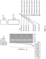
- FIG. 4 shows an example configuration in accordance with example embodiments of the invention.
- FIG. 4 shows RACH RO 405 and RACG ROG 410.
- FIG. 4 there is shown a sequence of 4 FDMed ROs 425 frequency division multiplexed over RACH slots 430.
- FIG. 4 also shows a relationship between the SSB indexes 440 and Preambles for beam indexes 450.
- FIG. 5 shows another example configuration in accordance with example embodiments of the invention.
- FIG. 5 shows RACH RO 405 and RACG ROG 410.
- FIG. 4 there is shown a sequence of 4 FDMed ROs 525 frequency division multiplexed over RACH slots 530.
- FIG. 5 also shows a relationship between the SSB indexes 540 and Preambles for beam indexes 550.
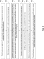
- FIG. 8 shows a method in accordance with example embodiments of the invention which may be performed by an apparatus.
- FIG. 8 illustrates operations which may be performed by a device such as, but not limited to, a device associated with the UE 10, gNB 12, and/or NN 13 as in FIG. 7 .
- step 810 of FIG. 8 there is receiving, by a user equipment of a communication network, information comprising a random access channel configuration and number of cycled beams.
- step 820 of FIG. 8 there is determining a number of random access channel occasions for a random access channel occasion group.
- step 830 of FIG. 8 there is associating synchronization signal blocks to a beam index given the number of cycled beams and transforming beams within the number of random access channel occasions of the random access channel occasion group, such that a same random access channel occasion is cloned within at least one selected random access channel occasion of the random access channel occasion group; at step 840 of FIG. 8 there is associating at least one beam index and at least one preamble of the random access channel occasion group.
- step 850 of FIG. 8 there is identifying a random access channel occasion group associated with the beam index.
- step 860 of FIG. 8 there is selecting at least one preamble associated with the at least one beam index in the random access channel occasion group.
- step 870 of FIG. 8 there is transmitting at least one preamble within each of the number of random access channel occasions of the random access channel occasion group to perform a random access channel procedure.
- the random access channel occasion group is identified based on the information that one of a half repetition or full repetition is used for the random access channel configuration.
- the random access channel occasion group is equal to a random access channel occasion.
- the random access channel occasion group comprises more than one random access channel occasion.
- the at least one preamble associated with the at least one beam index comprises the same preamble within each random access channel occasion of random access channel occasion group associated with the beam index.
- association is performed by mapping beams one-by-one in to preambles of random access channel occasion groups, code-first, time-second and frequency third.
- the set of cycled beams comprises a determined subset of beams, wherein the beams are defined by at least one value Q, and wherein the at least one value Q comprises an indication of at least one of a maximum number of cycled beam indices in serving cell, a maximum number of synchronization signal blocks, and maximum number of beam positions cycled in a Discovery Reference Signal burst.
- determining the number of random access channel occasions for the random access channel occasion group is using a number of the one of a half repetition or a full repetition.
- the determined subset of beams comprises at least one beam for which at least one SSB is indicated as transmitted.
- identifying that one of a half repetition or full repetition is used for the random access channel configuration comprises identifying a number of synchronization signal blocks per random access channel occasion group of the random access channel occasion group, and a number of channel bandwidth preambles per the number of synchronization signal blocks.
- a selected beam is based on a signal strength of at least one synchronization signal block of the number of synchronization signal blocks exceeding a threshold.
- the information is received from a network node of a communication network.
- the information comprises random access channel configuration to be used in a serving cell for the user equipment.
- a non-transitory computer-readable medium (MEM 12B, MEM 13B, and/or MEM 10B as in FIG. 7 ) storing program code (PROG 12C, PROG 13C, and/or PROG 10C as in FIG. 7 ), the program code executed by at least one processor (DP 12A, DP 13A, and/or DP 10A as in FIG. 7 ) to perform the operations as at least described in the paragraphs above.
- an apparatus comprising: means for receiving (TRANS 12D, TRANS 13D, and/or TRANS 10D, MEM 12B, MEM 13B, and/or MEM 10B, PROG 12C, PROG 13C, and/or 10C, DP 12A and/or 10A as in FIG. 7 ), by a user equipment (UE 10, gNB 12, and/or NN 13 as in FIG. 7 ) of a communication network (Network 1 as in FIG.
- information comprising a random access channel configuration and number of cycled beams; means for determining (TRANS 12D, TRANS 13D, and/or TRANS 10D, MEM 12B, MEM 13B, and/or MEM 10B, PROG 12C, PROG 13C, and/or 10C, DP 12A and/or 10A as in FIG. 7 ) a number of random access channel occasions for a random access channel occasion group; means for associating (TRANS 12D, TRANS 13D, and/or TRANS 10D, MEM 12B, MEM 13B, and/or MEM 10B, PROG 12C, PROG 13C, and/or 10C, DP 12A and/or 10A as in FIG.
- synchronization signal blocks to a beam index given the number of cycled beams and means for transforming (TRANS 12D, TRANS 13D, and/or TRANS 10D, MEM 12B, MEM 13B, and/or MEM 10B, PROG 12C, PROG 13C, and/or 10C, DP 12A and/or 10A as in FIG.
- a random access channel occasion group associated with the beam index; means for selecting at least one preamble associated with the at least one beam index in the random access channel occasion group; and means for transmitting (TRANS 12D, TRANS 13D, and/or TRANS 10D, MEM 12B, MEM 13B, and/or MEM 10B, PROG 12C, PROG 13C, and/or 10C, DP 12A and/or 10A as in FIG. 7 ) at least one preamble within each of the number of random access channel occasions of the random access channel occasion group to perform a random access channel procedure.
- At least means for receiving, identifying, determining, selecting, associating, and transmitting comprises transceiver [TRANS 12D, TRANS 13D, and/or TRANS 10D as in FIG. 7 ] a non-transitory computer readable medium [MEM 12B, MEM 13B, and/or MEM 10B as in FIG. 7 ] encoded with a computer program [PROG 12C, PROG 13C, and/or PROG 10C as in FIG. 7 ] executable by at least one processor [DP 12A, DP 13A, and/or DP 10A as in FIG. 7 ].
- advantages of operations in accordance with example embodiments of invention include at least that there is provided a missing functionality to provide RACH resources for repetition transmission mode as well as provides RACH resources that can be associated to beam indices while SSBs may be transmitted in cycled manner to overcome LBT failures.
- the various embodiments may be implemented in hardware or special purpose circuits, software, logic or any combination thereof.
- some aspects may be implemented in hardware, while other aspects may be implemented in firmware or software which may be executed by a controller, microprocessor or other computing device, although the invention is not limited thereto.
- firmware or software which may be executed by a controller, microprocessor or other computing device, although the invention is not limited thereto.
- While various aspects of the invention may be illustrated and described as block diagrams, flow charts, or using some other pictorial representation, it is well understood that these blocks, apparatus, systems, techniques or methods described herein may be implemented in, as non-limiting examples, hardware, software, firmware, special purpose circuits or logic, general purpose hardware or controller or other computing devices, or some combination thereof.
- Embodiments of the inventions may be practiced in various components such as integrated circuit modules.
- the design of integrated circuits is by and large a highly automated process.
- Complex and powerful software tools are available for converting a logic level design into a semiconductor circuit design ready to be etched and formed on a semiconductor substrate.
- connection means any connection or coupling, either direct or indirect, between two or more elements, and may encompass the presence of one or more intermediate elements between two elements that are “connected” or “coupled” together.
- the coupling or connection between the elements can be physical, logical, or a combination thereof.
- two elements may be considered to be “connected” or “coupled” together by the use of one or more wires, cables and/or printed electrical connections, as well as by the use of electromagnetic energy, such as electromagnetic energy having wavelengths in the radio frequency region, the microwave region and the optical (both visible and invisible) region, as several non-limiting and non-exhaustive examples.
Landscapes
- Engineering & Computer Science (AREA)
- Signal Processing (AREA)
- Computer Networks & Wireless Communication (AREA)
- Mobile Radio Communication Systems (AREA)
Applications Claiming Priority (1)
| Application Number | Priority Date | Filing Date | Title |
|---|---|---|---|
| US201962930642P | 2019-11-05 | 2019-11-05 |
Publications (3)
| Publication Number | Publication Date |
|---|---|
| EP3820236A1 EP3820236A1 (en) | 2021-05-12 |
| EP3820236C0 EP3820236C0 (en) | 2023-12-13 |
| EP3820236B1 true EP3820236B1 (en) | 2023-12-13 |
Family
ID=73005409
Family Applications (1)
| Application Number | Title | Priority Date | Filing Date |
|---|---|---|---|
| EP20203054.0A Active EP3820236B1 (en) | 2019-11-05 | 2020-10-21 | Verbesserung der direktzugriffskanalgelegenheit und ss/pbch-blockzuordnung |
Country Status (5)
| Country | Link |
|---|---|
| US (1) | US11432338B2 (zh) |
| EP (1) | EP3820236B1 (zh) |
| CN (1) | CN112788762B (zh) |
| ES (1) | ES2967711T3 (zh) |
| PL (1) | PL3820236T3 (zh) |
Families Citing this family (9)
| Publication number | Priority date | Publication date | Assignee | Title |
|---|---|---|---|---|
| US20200314673A1 (en) * | 2019-03-28 | 2020-10-01 | Qualcomm Incorporated | Techniques for measuring synchronization signal blocks in wireless communications |
| US20220394771A1 (en) * | 2021-06-02 | 2022-12-08 | Nokia Technologies Oy | Spectrum extension for initial access |
| CN115515250A (zh) * | 2021-06-07 | 2022-12-23 | 维沃移动通信有限公司 | 传输处理方法、终端及网络侧设备 |
| WO2022266997A1 (en) * | 2021-06-25 | 2022-12-29 | Qualcomm Incorporated | Random-access occasion selection for reduced-capability user equipment |
| US11956835B2 (en) * | 2021-10-05 | 2024-04-09 | Qualcomm Incorporated | Beamforming configurations for random access channel configuration |
| WO2023137658A1 (en) * | 2022-01-20 | 2023-07-27 | Qualcomm Incorporated | Methods and apparatuses for initial access |
| WO2023217351A1 (en) * | 2022-05-09 | 2023-11-16 | Nokia Technologies Oy | Method and apparatus for beam management |
| CN117121622A (zh) * | 2023-05-12 | 2023-11-24 | 上海移远通信技术股份有限公司 | 被用于无线通信的节点中的方法和装置 |
| CN117121621A (zh) * | 2023-06-30 | 2023-11-24 | 上海移远通信技术股份有限公司 | 被用于无线通信的节点中的方法和装置 |
Family Cites Families (13)
| Publication number | Priority date | Publication date | Assignee | Title |
|---|---|---|---|---|
| US11026261B2 (en) * | 2016-08-12 | 2021-06-01 | Qualcomm Incorporated | Rach conveyance of DL synchronization beam information for various DL-UL correspondence states |
| US10404434B2 (en) * | 2017-02-21 | 2019-09-03 | Qualcomm Incorporated | Discovery and random access for shared spectrum |
| BR112019019944A2 (pt) * | 2017-03-24 | 2020-04-28 | Mediatek Inc | aparelhos e métodos para identificação de feixe através do canal de acesso aleatório físico (prach) e utilização eficiente de recursos prach |
| CN114900890A (zh) * | 2017-05-05 | 2022-08-12 | 北京三星通信技术研究有限公司 | 基站、终端及随机接入前导检测、随机接入信道配置方法 |
| CN108809602B (zh) * | 2017-05-05 | 2022-06-03 | 北京三星通信技术研究有限公司 | 基站、终端及随机接入前导检测、随机接入信道配置方法 |
| CN109392150B (zh) * | 2017-08-11 | 2019-11-15 | 维沃移动通信有限公司 | 一种随机接入资源的处理方法和装置 |
| EP3689026B1 (en) * | 2017-09-28 | 2022-05-04 | Telefonaktiebolaget LM Ericsson (publ) | Multi-beam random access procedure in handover execution |
| US10893543B2 (en) | 2017-10-30 | 2021-01-12 | Samsung Electronics Co., Ltd. | Method and apparatus for random access design of NR unlicensed |
| EP3711431B1 (en) * | 2017-11-16 | 2022-06-01 | Telefonaktiebolaget LM Ericsson (publ) | Random access procedure |
| US10609735B2 (en) | 2017-11-17 | 2020-03-31 | Lg Electronics Inc. | Method of transmitting and receiving physical random access channel and device therefor |
| WO2019135654A1 (en) * | 2018-01-05 | 2019-07-11 | Samsung Electronics Co., Ltd. | Apparatus and method of beam recovery on secondary cell |
| EP3534666A4 (en) * | 2018-01-12 | 2020-06-03 | LG Electronics Inc. -1- | METHOD FOR SENDING AND RECEIVING A PHYSICAL DIRECT ACCESS CHANNEL AND DEVICE THEREFOR |
| US11147104B2 (en) * | 2018-05-11 | 2021-10-12 | Apple Inc. | PRACH resource selection |
-
2020
- 2020-10-21 ES ES20203054T patent/ES2967711T3/es active Active
- 2020-10-21 EP EP20203054.0A patent/EP3820236B1/en active Active
- 2020-10-21 PL PL20203054.0T patent/PL3820236T3/pl unknown
- 2020-10-28 US US17/082,960 patent/US11432338B2/en active Active
- 2020-11-04 CN CN202011215104.6A patent/CN112788762B/zh active Active
Also Published As
| Publication number | Publication date |
|---|---|
| PL3820236T3 (pl) | 2024-03-11 |
| EP3820236C0 (en) | 2023-12-13 |
| ES2967711T3 (es) | 2024-05-03 |
| EP3820236A1 (en) | 2021-05-12 |
| US20210136828A1 (en) | 2021-05-06 |
| CN112788762A (zh) | 2021-05-11 |
| CN112788762B (zh) | 2024-04-26 |
| US11432338B2 (en) | 2022-08-30 |
Similar Documents
| Publication | Publication Date | Title |
|---|---|---|
| EP3820236B1 (en) | Verbesserung der direktzugriffskanalgelegenheit und ss/pbch-blockzuordnung | |
| US11800371B2 (en) | Method and apparatus for wideband PRACH configuration for NR unlicensed | |
| US11229065B2 (en) | Network access of a wireless device to a communications network | |
| US10687367B2 (en) | System and method for random access backoffs | |
| US11523426B2 (en) | Methods, network nodes and devices for communicating at an unlicensed frequency spectrum | |
| KR102028661B1 (ko) | He-ltf 시퀀스를 전송하는 방법 및 장치 | |
| US9019916B2 (en) | RACH preamble response with flexible UL allocation | |
| CN109890083A (zh) | 在随机接入过程中进行数据传输和接收的方法 | |
| EP3624371A1 (en) | Method and device for generating scrambling code sequence | |
| KR20210122812A (ko) | 비면허 nr에서 유효 rach 기회 결정을 위한 방법 및 장치 | |
| CN111788861A (zh) | 用于执行随机接入的方法和装置 | |
| WO2017219284A1 (en) | Uplink transmission methods, assignment methods, user equipment, and base stations, using unlicensed spectrum | |
| EP4087344A1 (en) | Method and apparatus for determining initial bandwidth part (bwp), and storage medium | |
| US20220377619A1 (en) | Frequency domain resource allocation for interlaced transmission | |
| CN109152080A (zh) | 随机接入响应方法及网络设备、终端设备 | |
| US11088805B2 (en) | Control information transmission method, terminal device, and network device | |
| CN116326143A (zh) | 针对能力降低用户装备的随机接入消息传输 | |
| CN116325940A (zh) | 用于多trp操作的上行链路传输增强 | |
| EP3614611B1 (en) | Communication method and device | |
| CN113766648A (zh) | 一种ssb传输方法和装置及设备 | |
| EP3648531A1 (en) | Anchor channel transmission method and apparatus, and communication apparatus | |
| WO2018202476A1 (en) | SCHEDULING REQUEST METHOD FOR NARROW BAND IoT | |
| US20240188122A1 (en) | System and method to determine initial bandwidth part for a reduced capacity device | |
| JP2024503370A (ja) | ランダムアクセス方法及び装置 |
Legal Events
| Date | Code | Title | Description |
|---|---|---|---|
| PUAI | Public reference made under article 153(3) epc to a published international application that has entered the european phase |
Free format text: ORIGINAL CODE: 0009012 |
|
| STAA | Information on the status of an ep patent application or granted ep patent |
Free format text: STATUS: THE APPLICATION HAS BEEN PUBLISHED |
|
| AK | Designated contracting states |
Kind code of ref document: A1 Designated state(s): AL AT BE BG CH CY CZ DE DK EE ES FI FR GB GR HR HU IE IS IT LI LT LU LV MC MK MT NL NO PL PT RO RS SE SI SK SM TR |
|
| STAA | Information on the status of an ep patent application or granted ep patent |
Free format text: STATUS: REQUEST FOR EXAMINATION WAS MADE |
|
| 17P | Request for examination filed |
Effective date: 20211101 |
|
| RBV | Designated contracting states (corrected) |
Designated state(s): AL AT BE BG CH CY CZ DE DK EE ES FI FR GB GR HR HU IE IS IT LI LT LU LV MC MK MT NL NO PL PT RO RS SE SI SK SM TR |
|
| RIC1 | Information provided on ipc code assigned before grant |
Ipc: H04W 74/00 20090101ALN20230428BHEP Ipc: H04L 5/00 20060101ALI20230428BHEP Ipc: H04B 7/06 20060101ALI20230428BHEP Ipc: H04W 74/08 20090101AFI20230428BHEP |
|
| GRAP | Despatch of communication of intention to grant a patent |
Free format text: ORIGINAL CODE: EPIDOSNIGR1 |
|
| STAA | Information on the status of an ep patent application or granted ep patent |
Free format text: STATUS: GRANT OF PATENT IS INTENDED |
|
| GRAJ | Information related to disapproval of communication of intention to grant by the applicant or resumption of examination proceedings by the epo deleted |
Free format text: ORIGINAL CODE: EPIDOSDIGR1 |
|
| INTG | Intention to grant announced |
Effective date: 20230609 |
|
| STAA | Information on the status of an ep patent application or granted ep patent |
Free format text: STATUS: REQUEST FOR EXAMINATION WAS MADE |
|
| INTC | Intention to grant announced (deleted) | ||
| RIC1 | Information provided on ipc code assigned before grant |
Ipc: H04W 74/00 20090101ALN20230710BHEP Ipc: H04L 5/00 20060101ALI20230710BHEP Ipc: H04B 7/06 20060101ALI20230710BHEP Ipc: H04W 74/08 20090101AFI20230710BHEP |
|
| GRAP | Despatch of communication of intention to grant a patent |
Free format text: ORIGINAL CODE: EPIDOSNIGR1 |
|
| STAA | Information on the status of an ep patent application or granted ep patent |
Free format text: STATUS: GRANT OF PATENT IS INTENDED |
|
| INTG | Intention to grant announced |
Effective date: 20230831 |
|
| GRAS | Grant fee paid |
Free format text: ORIGINAL CODE: EPIDOSNIGR3 |
|
| GRAA | (expected) grant |
Free format text: ORIGINAL CODE: 0009210 |
|
| STAA | Information on the status of an ep patent application or granted ep patent |
Free format text: STATUS: THE PATENT HAS BEEN GRANTED |
|
| AK | Designated contracting states |
Kind code of ref document: B1 Designated state(s): AL AT BE BG CH CY CZ DE DK EE ES FI FR GB GR HR HU IE IS IT LI LT LU LV MC MK MT NL NO PL PT RO RS SE SI SK SM TR |
|
| REG | Reference to a national code |
Ref country code: GB Ref legal event code: FG4D |
|
| REG | Reference to a national code |
Ref country code: CH Ref legal event code: EP |
|
| REG | Reference to a national code |
Ref country code: DE Ref legal event code: R096 Ref document number: 602020022621 Country of ref document: DE |
|
| REG | Reference to a national code |
Ref country code: IE Ref legal event code: FG4D |
|
| U01 | Request for unitary effect filed |
Effective date: 20231222 |
|
| U07 | Unitary effect registered |
Designated state(s): AT BE BG DE DK EE FI FR IT LT LU LV MT NL PT SE SI Effective date: 20240109 |
|
| REG | Reference to a national code |
Ref country code: GR Ref legal event code: EP Ref document number: 20240400117 Country of ref document: GR Effective date: 20240209 |
|
| REG | Reference to a national code |
Ref country code: ES Ref legal event code: FG2A Ref document number: 2967711 Country of ref document: ES Kind code of ref document: T3 Effective date: 20240503 |