EP3820221B1 - Communication method and apparatus - Google Patents
Communication method and apparatus Download PDFInfo
- Publication number
- EP3820221B1 EP3820221B1 EP19847074.2A EP19847074A EP3820221B1 EP 3820221 B1 EP3820221 B1 EP 3820221B1 EP 19847074 A EP19847074 A EP 19847074A EP 3820221 B1 EP3820221 B1 EP 3820221B1
- Authority
- EP
- European Patent Office
- Prior art keywords
- terminal
- pdcch
- monitoring
- group
- search spaces
- Prior art date
- Legal status (The legal status is an assumption and is not a legal conclusion. Google has not performed a legal analysis and makes no representation as to the accuracy of the status listed.)
- Active
Links
- 238000004891 communication Methods 0.000 title claims description 58
- 238000000034 method Methods 0.000 title claims description 49
- 238000012544 monitoring process Methods 0.000 claims description 345
- 230000011664 signaling Effects 0.000 claims description 54
- 230000002776 aggregation Effects 0.000 claims description 34
- 238000004220 aggregation Methods 0.000 claims description 34
- 230000006870 function Effects 0.000 description 15
- 238000001514 detection method Methods 0.000 description 7
- 238000004590 computer program Methods 0.000 description 6
- 238000010586 diagram Methods 0.000 description 6
- 230000004044 response Effects 0.000 description 6
- 239000000969 carrier Substances 0.000 description 4
- 230000003287 optical effect Effects 0.000 description 4
- 230000008569 process Effects 0.000 description 4
- 230000003068 static effect Effects 0.000 description 4
- 238000010295 mobile communication Methods 0.000 description 3
- 230000008859 change Effects 0.000 description 2
- 238000005516 engineering process Methods 0.000 description 2
- 230000000977 initiatory effect Effects 0.000 description 2
- 230000007774 longterm Effects 0.000 description 2
- 238000003491 array Methods 0.000 description 1
- 230000005540 biological transmission Effects 0.000 description 1
- 230000001413 cellular effect Effects 0.000 description 1
- 239000003795 chemical substances by application Substances 0.000 description 1
- 230000007423 decrease Effects 0.000 description 1
- 230000005611 electricity Effects 0.000 description 1
Images


Classifications
-
- H—ELECTRICITY
- H04—ELECTRIC COMMUNICATION TECHNIQUE
- H04W—WIRELESS COMMUNICATION NETWORKS
- H04W24/00—Supervisory, monitoring or testing arrangements
- H04W24/08—Testing, supervising or monitoring using real traffic
-
- H—ELECTRICITY
- H04—ELECTRIC COMMUNICATION TECHNIQUE
- H04L—TRANSMISSION OF DIGITAL INFORMATION, e.g. TELEGRAPHIC COMMUNICATION
- H04L5/00—Arrangements affording multiple use of the transmission path
- H04L5/003—Arrangements for allocating sub-channels of the transmission path
- H04L5/0053—Allocation of signaling, i.e. of overhead other than pilot signals
-
- H—ELECTRICITY
- H04—ELECTRIC COMMUNICATION TECHNIQUE
- H04W—WIRELESS COMMUNICATION NETWORKS
- H04W52/00—Power management, e.g. TPC [Transmission Power Control], power saving or power classes
- H04W52/02—Power saving arrangements
- H04W52/0209—Power saving arrangements in terminal devices
- H04W52/0212—Power saving arrangements in terminal devices managed by the network, e.g. network or access point is master and terminal is slave
- H04W52/0216—Power saving arrangements in terminal devices managed by the network, e.g. network or access point is master and terminal is slave using a pre-established activity schedule, e.g. traffic indication frame
-
- H—ELECTRICITY
- H04—ELECTRIC COMMUNICATION TECHNIQUE
- H04W—WIRELESS COMMUNICATION NETWORKS
- H04W72/00—Local resource management
- H04W72/04—Wireless resource allocation
- H04W72/044—Wireless resource allocation based on the type of the allocated resource
- H04W72/0446—Resources in time domain, e.g. slots or frames
-
- H—ELECTRICITY
- H04—ELECTRIC COMMUNICATION TECHNIQUE
- H04W—WIRELESS COMMUNICATION NETWORKS
- H04W72/00—Local resource management
- H04W72/20—Control channels or signalling for resource management
- H04W72/23—Control channels or signalling for resource management in the downlink direction of a wireless link, i.e. towards a terminal
-
- H—ELECTRICITY
- H04—ELECTRIC COMMUNICATION TECHNIQUE
- H04L—TRANSMISSION OF DIGITAL INFORMATION, e.g. TELEGRAPHIC COMMUNICATION
- H04L5/00—Arrangements affording multiple use of the transmission path
- H04L5/0001—Arrangements for dividing the transmission path
- H04L5/0003—Two-dimensional division
- H04L5/0005—Time-frequency
- H04L5/0007—Time-frequency the frequencies being orthogonal, e.g. OFDM(A), DMT
-
- H—ELECTRICITY
- H04—ELECTRIC COMMUNICATION TECHNIQUE
- H04L—TRANSMISSION OF DIGITAL INFORMATION, e.g. TELEGRAPHIC COMMUNICATION
- H04L5/00—Arrangements affording multiple use of the transmission path
- H04L5/0091—Signaling for the administration of the divided path
- H04L5/0094—Indication of how sub-channels of the path are allocated
-
- H—ELECTRICITY
- H04—ELECTRIC COMMUNICATION TECHNIQUE
- H04W—WIRELESS COMMUNICATION NETWORKS
- H04W76/00—Connection management
- H04W76/20—Manipulation of established connections
- H04W76/28—Discontinuous transmission [DTX]; Discontinuous reception [DRX]
-
- Y—GENERAL TAGGING OF NEW TECHNOLOGICAL DEVELOPMENTS; GENERAL TAGGING OF CROSS-SECTIONAL TECHNOLOGIES SPANNING OVER SEVERAL SECTIONS OF THE IPC; TECHNICAL SUBJECTS COVERED BY FORMER USPC CROSS-REFERENCE ART COLLECTIONS [XRACs] AND DIGESTS
- Y02—TECHNOLOGIES OR APPLICATIONS FOR MITIGATION OR ADAPTATION AGAINST CLIMATE CHANGE
- Y02D—CLIMATE CHANGE MITIGATION TECHNOLOGIES IN INFORMATION AND COMMUNICATION TECHNOLOGIES [ICT], I.E. INFORMATION AND COMMUNICATION TECHNOLOGIES AIMING AT THE REDUCTION OF THEIR OWN ENERGY USE
- Y02D30/00—Reducing energy consumption in communication networks
- Y02D30/70—Reducing energy consumption in communication networks in wireless communication networks
Definitions
- This application relates to the field of communications technologies, and in particular, to communication methods and devices.
- the base station may send, to the terminal by using radio resource control (radio resource control, RRC) signaling, the one or more search spaces configured for the terminal and a monitoring parameter corresponding to each search space, and the terminal monitors the PDCCH in a corresponding search space based on the received monitoring parameter.
- RRC radio resource control
- the base station determines only the search space and the monitoring parameter that need to be currently used by the terminal. In this case, configuration is not flexible enough.
- US 2018/019844 A1 discloses a user equipment (UE).
- a higher-layer processor is configured to configure a short processing time.
- a PDCCH receiver is configured to receive, in a subframe n, a PDCCH.
- a physical downlink shared channel (PDSCH) receiver is configured to receive, in the subframe n, a PDSCH corresponding to the PDCCH.
- An uplink receiver is configured to feedback, in a subframe n+k, a hybrid automatic repeat request-acknowledgement (HARQ-ACK) corresponding to the PDSCH.
- HARQ-ACK hybrid automatic repeat request-acknowledgement
- the k is equal to k 1 .
- the PDCCH is a PDCCH in UE-specific search space
- the k is equal to k 2 .
- the k 2 is smaller than the k 1 .
- This application provides communication methods and devices to send one or more groups of search spaces and a plurality of groups of PDCCH monitoring parameters to a terminal, so that the terminal monitors a PDCCH in one group of search spaces based on one group of monitoring parameters.
- a base station may send, to a terminal by using RRC signaling, one or more search spaces configured for the terminal and a monitoring parameter corresponding to each search space.
- the terminal monitors a PDCCH in a corresponding search space based on the received monitoring parameter.
- the base station determines only the search space and the monitoring parameter that need to be currently used by the terminal. In this case, configuration is not flexible enough.
- the embodiments of this application provide a communication method and a communications apparatus.
- the method and the apparatus may be applied to a 5th generation (the 5th generation, 5G) mobile communications system, a long term evolution (long term evolution, LTE) system, or another communications system.
- the embodiments of this application may be applied to a scenario shown in FIG. 1 .
- a network device in the embodiments of this application is a base station
- the base station may be configured to mutually convert a received over-the-air frame and an Internet protocol (Internet Protocol, IP) packet and serve as a router between a wireless terminal and a rest portion of an access network, where the rest portion of the access network may include an IP network.
- IP Internet Protocol
- the network device may be further configured to coordinate attribute management of the air interface.
- devices having a base station function may have different names.
- a base station in a global system for mobile communications (global system for mobile communications, GSM) or a code division multiple access (code division multiple access, CDMA) system is referred to as a base transceiver station (base transceiver station, BTS); a base station in a wideband code division multiple access (wideband code division multiple access, WCDMA) system is referred to as a nodeB (nodeB); a base station in an LTE system is referred to as an evolved nodeB (evolutional nodeB, eNB); a base station in an NR system is referred to as a general nodeB (general nodeB, gNB). This is not limited in the embodiments of this application.
- the terminal device in the embodiments of this application may also be referred to as user equipment (user equipment, UE), an access terminal device, a subscriber unit, a subscriber station, a mobile station, a mobile console, a remote station, a remote terminal device, a mobile device, a user terminal device, a terminal device, a wireless communication device, a user agent, a user apparatus, or the like.
- user equipment user equipment
- UE user equipment
- an access terminal device a subscriber unit, a subscriber station, a mobile station, a mobile console, a remote station, a remote terminal device, a mobile device, a user terminal device, a terminal device, a wireless communication device, a user agent, a user apparatus, or the like.
- the terminal device may be a cellular phone, a cordless phone, a session initiation protocol (session initiation protocol, SIP) phone, a wireless local loop (wireless local loop, WLL) station, a personal digital assistant (personal digital assistant, PDA), a handheld device having a wireless communication function, a computing device, another processing device connected to a wireless modem, a vehicle-mounted device, a wearable device, a terminal device in a future 5G network, or a terminal device in a future evolved public land mobile network (public land mobile network, PLMN).
- SIP session initiation protocol
- WLL wireless local loop
- PDA personal digital assistant
- PLMN public land mobile network
- FIG. 2 is a schematic flowchart of a communication method according to an embodiment of this application. As shown in the figure, the method may include the following steps.
- Step 201 A network device sends first information to a terminal.
- the first information is used to indicate a first search space, a second space, a first monitoring parameter, and a second monitoring parameter.
- the first monitoring parameter is a monitoring parameter for monitoring a PDCCH in the first search space by the terminal.
- the second monitoring parameter is a monitoring parameter for monitoring a PDCCH in the second search space by the terminal.
- the first search space and the second search space may be a same search space but the first monitoring parameter is different from the second monitoring parameter.
- the terminal may monitor a PDCCH in a same search space based on different monitoring parameters in different duration, different working modes, and different scenarios.
- the first search space and the second search space may be different search spaces but the first monitoring parameter may be the same as the second monitoring parameter.
- the terminal may monitor a PDCCH in different search spaces based on a same monitoring parameter in different duration, different working modes, and different scenarios.
- the first search space is different from the second search space and the first monitoring parameter is also different from the second monitoring parameter.
- the terminal may monitor a PDCCH in different search spaces based on monitoring parameters of the search spaces in different duration, different working modes, and different scenarios.
- Step 202 The network device sends the PDCCH in the first search space based on the first monitoring parameter, and the terminal monitors the PDCCH in the first search space based on the first monitoring parameter; or the network device sends the PDCCH in the second search space based on the second monitoring parameter, and the terminal monitors the PDCCH in the second search space based on the second monitoring parameter.
- the network device sends a search space and a corresponding monitoring parameter to the terminal, and the terminal performs monitoring in all search spaces indicated by the network device. If the search space or the monitoring parameter needs to be changed, the network device needs to send a changed search space and all monitoring parameters to the terminal.
- the first information sent by the network device may carry a plurality of groups of search spaces and a plurality of groups of monitoring parameters, and the terminal monitors the PDCCH in one group of search spaces based on corresponding monitoring parameters instead of monitoring the PDCCH in all the search spaces. If the search space or the monitoring parameter needs to be changed, instead of sending the search space and all the monitoring parameters, the network device only needs to instruct the terminal to switch the search space or the monitoring parameter.
- the first information described in the foregoing embodiment includes the first search space, the second search space, the first monitoring parameter, and the second monitoring parameter does not indicate that the first information includes only these pieces of information.
- the first information may further include a third search space, a third monitoring parameter, and the like.
- the network device may further indicate that the third search space and the third monitoring parameter belong to a same first monitoring group as the first search space and the first monitoring parameter. In other words, in same duration, the terminal may monitor the PDCCH in the first search space based on the first monitoring parameter, and may also monitor the PDCCH in the third search space based on the third monitoring parameter. Alternatively, the network device may indicate that the third search space and the third monitoring parameter belong to a same second monitoring group as the second search space and the second monitoring parameter. In other words, in same duration, the terminal may monitor the PDCCH in the second search space based on the second monitoring parameter, and may also monitor the PDCCH in the third search space based on the third monitoring parameter.
- the network device may indicate that the third search space and the third monitoring parameter belong to a third monitoring group.
- the terminal monitors the PDCCH in the third search space based on the third monitoring parameter
- the terminal does not monitor the PDCCH in the first search space based on the first monitoring parameter, and also does not monitor the PDCCH in the second search space based on the second monitoring parameter.
- the foregoing monitoring parameter may include one of or a combination of the following parameters: Format of monitored DCI (DCI format):
- DCI format The DCI transmitted by the network device by using the PDCCH has a plurality of formats. Different formats are used based on different purposes and scenarios. For example, DCI used to schedule a physical uplink shared channel (physical uplink shared channel, PUSCH) may have a format different from DCI used to schedule a physical downlink shared channel (physical downlink shared channel, PDSCH).
- the network device may instruct the terminal to monitor DCI in one or more formats in a corresponding search space.
- a format of DCI that the network device may instruct the terminal to monitor in the first search space is DCI-format0-0-AndFormat1-0, DCI-format2-0, DCI-format2-1, DCI-format2-2, or DCI-format2-3; and a format of DCI that the network device may instruct the terminal to monitor in the second search space is DCI-format0-0-AndFormat1-0, or DCI-format2-0.
- the network device may configure a monitoring periodicity for the terminal, to instruct the terminal to monitor a PDCCH in a search space based on the monitoring periodicity.
- the monitoring periodicity may be in a unit of a slot. For example, if the monitoring periodicity indicated by the network device is 8, it indicates that the monitoring periodicity is eight slots.
- the unit of the monitoring periodicity is not limited to a slot, and may alternatively be millisecond (ms), a subframe, or the like.
- the monitoring slot is used to indicate a slot in which the terminal monitors a PDCCH. Generally, the terminal monitors one slot in one monitoring periodicity. For example, if the network device may indicate that the monitoring periodicity is 10 slots, the monitoring slot is a slot 0. Certainly, the terminal may also monitor a plurality of slots in one monitoring periodicity. If the plurality of monitored slots are consecutive slots, a monitoring slot parameter may further include a monitoring start slot and monitoring duration. The monitoring start slot indicates a slot from which the terminal starts to perform monitoring in one monitoring periodicity, and the monitoring duration indicates a quantity of continuously monitored slots in one monitoring periodicity. Alternatively, the network device may indicate, by using a bitmap, specified slots in which monitoring is performed in one monitoring periodicity.
- the two parameters: the monitoring periodicity and the monitoring slot are sent together to the terminal for use, and are sent to the terminal by using a “monitoring slot periodicity and offset (monitoringSlotPeriodicityAndOffset)" parameter.
- Monitoring duration (duration) in a to-be-monitored slot The duration is used to indicate duration of monitoring performed by the terminal in a slot that needs to be monitored. A unit of the duration may be a symbol.
- monitoringSymbolsWithinSlot The symbol is used to indicate a start symbol of monitoring a PDCCH by the terminal in a slot that needs to be monitored.
- one slot includes 14 symbols that respectively correspond to 14 bits. If a value of the 14 bits is 10000001000000, it indicates that the terminal starts to monitor a PDCCH from a symbol 0 and a symbol 7 in one to-be-monitored slot. Further, if a value of duration is 3, that is, one time of monitoring lasts for three symbols, the terminal monitors a PDCCH on a symbol 0, a symbol 1, a symbol 2, a symbol 7, a symbol 8, and a symbol 9.
- the aggregation level indicates a quantity of control channel elements (control channel element, CCE) included in one PDCCH. If one PDCCH includes one CCE, an aggregation level of the PDCCH is 1; if one PDCCH includes two CCEs, an aggregation level of the PDCCH is 2; and so on. Common aggregation levels are 1, 2, 4, 8, and 16.
- the quantity of monitored PDCCH candidate locations indicates a maximum quantity of PDCCH candidate locations monitored in a search space by the terminal. For example, if one search space includes eight CCEs, for a PDCCH whose aggregation level is 1, there are eight PDCCH candidate locations. If a quantity that is of monitored PDCCH candidate locations and that is indicated by the network device is 6, it indicates that the terminal selects, according to a preset rule, six PDCCH candidate locations from the eight PDCCH candidate locations for monitoring.
- searchSpaceType The type is used to indicate whether a search space indicated by the network device is a common search space (common) or a user equipment-specific search space (UE-specific).
- the network device may further send second information to the terminal.
- the second information is used to instruct the terminal to monitor the PDCCH in the first search space based on the first monitoring parameter, or is used to instruct the terminal to monitor the PDCCH in the second search space based on the second monitoring parameter.
- the network device determines a specified search space and a specified monitoring parameter, and instructs the terminal to monitor the PDCCH in the specified search space based on the specified monitoring parameter.
- the network device may preconfigure that the first search space and the first monitoring parameter correspond to an index 1, the second search space and the second monitoring parameter correspond to an index 2, and the third search space and the third monitoring parameter correspond to an index 3. If the network device determines that the terminal should monitor the PDCCH in the first search space based on the first monitoring parameter, and determines that the network device sends the PDCCH in the first search space based on the first monitoring parameter, the second information sent by the network device may include indication information of the index 1. If the network device determines that the terminal should monitor the PDCCH in the second search space based on the second monitoring parameter and monitor the PDCCH in the third search space based on the third monitoring parameter, the second information sent by the network device may include indication information of the index 2 and the index 3.
- the network device may preconfigure that the first search space, the first monitoring parameter, the third search space, and the third monitoring parameter correspond to a monitoring group 1, and the second search space and the second monitoring parameter correspond to a monitoring group 2. If the network device determines that the network device sends the PDCCH based on the monitoring parameters in the monitoring group 1 and the terminal should monitor the PDCCH based on the monitoring parameters in the monitoring group 1, the second information sent by the network device may include indication information of the monitoring group 1.
- the network device may add the first information and the second information to same signaling, and send the signaling to the terminal.
- the first information is usually sent to the terminal by using RRC signaling.
- the network device may add the first information and the second information to the RRC signaling, and send the RRC signaling to the terminal.
- the network device may alternatively send the first information and the second information to the terminal by using other signaling. This is not limited in this embodiment of this application.
- the network device may send the first information and the second information to the terminal by using different signaling.
- the network device may send the second information to the terminal by using DCI, a MAC CE, or RRC signaling.
- the DCI signaling belongs to physical layer signaling
- the MAC CE signaling belongs to MAC layer signaling
- the RRC signaling belongs to RRC layer signaling.
- a delay is relatively short; if the second information is sent by using the RRC signaling, a delay is relatively long; or if the second information is sent by using the MAC CE signaling, a delay is between the delay of performing sending by using the DCI signaling and the delay of performing sending by using the RRC signaling.
- the network device may further send an indication information to the terminal when determining that the search space and the monitoring parameter for monitoring the PDCCH by the terminal need to be changed, to indicate the changed search space and the changed monitoring parameter to the terminal.
- the indication information may include index information of the changed search space and the changed monitoring parameter, or include index information of the changed monitoring group.
- the indication information may also be sent to the terminal by using DCI, a MAC CE, or RRC signaling.
- the network device determines that the search space and the monitoring parameter for the terminal need to be changed, the network device sends the changed search space and the corresponding monitoring parameter to the terminal through an RRC reconfiguration process.
- signaling overheads are relatively high.
- the network device has sent the plurality of possible search spaces and the corresponding monitoring parameters in the first information to the terminal.
- the indication information may include only the index information corresponding to the changed search space and the monitoring parameter, thereby reducing signaling overheads.
- the indication information is sent by using DCI or MAC CE information, a delay is further reduced.
- step S202 may specifically include two cases shown in FIG. 3 : Step 202a: If the terminal is in a first working mode, the network device sends the PDCCH in the first search space based on the first monitoring parameter, and the terminal monitors the PDCCH in the first search space based on the first monitoring parameter.
- Step 202b If the terminal is in a second working mode, the network device sends the PDCCH in the second search space based on the second monitoring parameter, and the terminal monitors the PDCCH in the second search space based on the second monitoring parameter.
- the network device may preconfigure that the first search space and the first monitoring parameter correspond to the first working mode, and the second search space and the second monitoring parameter correspond to the second working mode.
- the network device and the terminal may determine, based on a current working mode of the terminal, the search space and the monitoring parameter that are used for sending/monitoring the PDCCH.
- working parameters corresponding to the first working mode include the first search space and the first monitoring parameter.
- the first working mode may further be related to parameters such as a value of an operating bandwidth of the terminal, a quantity of activated carriers, and a quantity of transmit/receive antennas during multiple-antenna multiple-input multiple-output (multiple-input multiple-output, MIMO) communication.
- MIMO multiple-input multiple-output
- the network device configures that: an operating bandwidth of the terminal is 20 MHz, three carriers are activated, the terminal monitors the PDCCH in a search space 1 based on a monitoring parameter 1, and the like, when the terminal works in the first working mode; and an operating bandwidth of the terminal is 10 MHz, one carrier is activated, the terminal monitors the PDCCH in a search space 1 based on a monitoring parameter 1, and the like, when the terminal works in the second working mode.
- the terminal determines to switch from the first working mode to the second working mode
- the terminal monitors the PDCCH in a search space 2 based on a monitoring parameter 2
- the working bandwidth is switched from 20 MHz to 10 MHz, and three activated carriers is changed to one activated carrier.
- various parameters configured by the network device may be sent to the terminal by using a same piece of signaling or a plurality of pieces of signaling.
- the terminal monitors the PDCCH in the second search space based on the second monitoring parameter.
- the network device sends the PDCCH in the second search space based on the second monitoring parameter.
- the network device may send the third information to the terminal by using DCI, a MAC CE, or RRC signaling.
- a working mode switching policy of the terminal may be preconfigured in both the network device and the terminal.
- the network device and the terminal may both determine the current working mode of the terminal based on factors such as the working mode switching policy, a current network environment, a status of the terminal, and a requirement of the terminal. For example, if the network device does not send the DCI to the terminal in preset duration, the terminal and the network device may determine to switch the working mode of the terminal according to the preset working mode switching policy, to reduce a quantity of times that the terminal monitors the PDCCH. In this case, the network device may not need to send, to the terminal, a information used to indicate the working mode.
- a working mode switching policy may be preconfigured in the terminal.
- the terminal determines a current working mode based on factors such as the working mode switching policy, a current network environment, a status of the terminal, and a requirement of the terminal.
- the terminal may send a fourth information to the network device, to notify the network device of a switched-to working mode, so that the network device sends a PDCCH and the terminal monitors the PDCCH in a same search space based on a same monitoring parameter.
- the fourth information may be sent to the network device by using uplink control information (uplink control information, UCI), a MAC CE, or RRC signaling.
- the terminal may switch to a power saving mode.
- the power saving mode corresponds to the search space 1 and the monitoring parameter 1.
- a maximum quantity of times that the terminal monitors the PDCCH is less than a maximum quantity of monitoring times in another working mode.
- the terminal monitors the PDCCH in the search space 1 based on the monitoring parameter 1.
- the terminal sends the fourth information to the network device.
- the fourth information is used to indicate that the terminal switches to the power saving mode. Therefore, the network device sends the PDCCH in the search space 1 based on the monitoring parameter.
- the network device may send a response information to the terminal, to indicate whether the network device successfully switches the working mode, thereby ensuring that the terminal and the network device work in the same working mode.
- a information is incorrectly sent or received due to different working modes of the terminal and the network device.
- the response information sent by the network device may be used to indicate whether the switching succeeds. For example, "1" is used to indicate that the switching succeeds, and "0" is used to indicate that the switching fails.
- the network device may add, to the response information, information about the working mode currently determined by the network device.
- the response information carries information about the working mode 2. If the switching fails, the response information carries a information of the working mode 1.
- the response information is similar to the third information in the foregoing embodiment, and is used to instruct the terminal to work in the corresponding working mode based on the information about the working mode carried in the information.
- step S202 may alternatively specifically include two cases shown in FIG. 4 : Step 202c: If DRX is configured for the terminal, the network device sends the PDCCH in the first search space based on the first monitoring parameter, and the terminal monitors the PDCCH in the first search space based on the first monitoring parameter.
- Step 202d If DRX is not configured for the terminal, the network device sends the PDCCH in the second search space based on the second monitoring parameter, and the terminal monitors the PDCCH in the second search space based on the second monitoring parameter.
- the network device may preconfigure that the first search space and the first monitoring parameter correspond to a case in which DRX is configured for the terminal, and the second search space and the second monitoring parameter correspond to a case in which DRX is not configured for the terminal.
- the network device and the terminal may determine, based on whether DRX is currently configured for the terminal, the search space and the monitoring parameter that are used for sending/monitoring the PDCCH.
- DRX may be configured for the terminal in an RRC_CONNECTED (RRC_connected) mode.
- RRC_CONNECTED RRC_connected
- the terminal instead of continuously monitoring the PDCCH, the terminal monitors the PDCCH in on duration (on duration) and does not monitor the PDCCH in an opportunity for DRX (opportunity for DRX), thereby reducing power consumption of the terminal.
- One on duration and one opportunity for DRX form one DRX cycle.
- the terminal may monitor the PDCCH according to the monitoring periodicity in the foregoing embodiment. Because a monitoring time is relatively long, the PDCCH may be monitored by using a monitoring parameter by using which a quantity of times of monitoring the PDCCH in one monitoring periodicity is relatively small. If DRX is configured for the terminal, the PDCCH may be monitored by using a monitoring parameter by using which a quantity of times of monitoring the PDCCH in one monitoring periodicity is relatively large.
- step 202 may alternatively specifically include two cases shown in FIG. 6 : Step 202e: If a first DRX parameter is configured for the terminal, the network device sends the PDCCH in the first search space based on the first monitoring parameter, and the terminal monitors the PDCCH in the first search space based on the first monitoring parameter.
- first DRX parameter and the foregoing second DRX parameter may separately include one or more parameters.
- first DRX parameter and the second DRX parameter may be used to indicate parameter groups.
- the network device may send RRC signaling to the terminal.
- the signaling may include a list of to-be-added search spaces (searchSpacesToAddModList) and a list of to-be-deleted search spaces (searchSpacesToReleaseList) to indicate a search space of the PDCCH of the terminal.
- the foregoing parameters may still be used to indicate the first search space of the terminal, and an index corresponding to the first search space may be normal (normal).
- An index corresponding to the second search space may be power saving (powerSaving).
- the network device may further add a new parameter (usage) to the foregoing information.
- a value of the parameter may indicate normal or powerSaving, that is, the parameter is used to indicate whether the terminal monitors the PDCCH by using the first search space or by using the second search space.
- the parameter may also be default. If the parameter is default, the terminal uses a default value: normal.
- the network device may send, to the terminal by using DCI, a MAC CE, or RRC signaling, an indication information including the foregoing parameter (usage).
- the network device may send, to the terminal by using DCI, a MAC CE, or RRC signaling, the indication information including the foregoing parameter (usage), to indicate a changed search space to the terminal.
- the network device may send RRC signaling to the terminal.
- the signaling may include a monitoring slot periodicity and offset (monitoringSlotPeriodicityAndOffset), a monitoring start symbol in a to-be-monitored slot (monitoringSymbolsWithinSlot), monitoring duration (duration) in a to-be-monitored slot, an aggregation level of a monitored PDCCH, and a quantity (nrofCandidates) of PDCCH candidate locations that need to be monitored at the aggregation level.
- a new parameter a monitoring slot periodicity and offset for power saving (monitoringSlotPeriodicityAndOffsetForPowerSaving) is added, to indicate that the monitoring periodicity is 10 slots and monitoring is performed on the slot 0; and new parameters: a monitoring start symbol in a to-be-monitored slot for power saving (monitoringSymbolsWithinSlot ForPowerSaving) and monitoring duration in a to-be-monitored slot for power saving (durationForPowerSaving) are added, to indicate that monitoring is performed on a symbol 0, a symbol 1, and a symbol 2 in one to-be-monitored slot.
- monitoringSlotPeriodicityAndOffsetForPowerSaving a monitoring start symbol in a to-be-monitored slot for power saving
- monitoring durationForPowerSaving monitoring duration in a to-be-monitored slot for power saving
- the aggregation level of the monitored PDCCH and the quantity (nrofCandidates) of PDCCH candidate locations that need to be monitored at the aggregation level are shown in Table 2.
- the network device may further add a new parameter (usage).
- a value of the parameter may indicate normal or powerSaving, that is, the parameter is used to indicate whether the terminal uses the first monitoring parameter or uses the second monitoring parameter.
- the parameter may also be default. If the parameter is default, the terminal uses a default value: normal.
- the network device may send, to the terminal by using DCI, a MAC CE, or RRC signaling, an indication information including the foregoing parameter (usage).
- the terminal may have two working modes: a normal working mode (normal mode) and a power saving mode (power saving mode).
- Each search space corresponds to one working mode.
- the search space 1 and the monitoring parameter 1 correspond to a middle-class working mode
- the search space 2 and the monitoring parameter 2 correspond to a power-saving working mode.
- Information that is of the search space and the monitoring parameter and that is sent by the network device to the terminal is similar to that in Embodiments 1 and 2. Details are not described herein again.
- the network device may send DCI, a MAC CE, or RRC signaling to the terminal.
- the signaling includes a working mode parameter (mode).
- a value of the parameter may indicate the normal working mode or the power saving working mode, to indicate the working mode of the terminal.
- the working mode that is of the terminal and that is indicated by the network device is not merely used to indicate the search space and the monitoring parameter for monitoring the PDCCH by the terminal, and may be further used to indicate a value of an operating bandwidth of the terminal, a quantity of activated carriers, and the like.
- the network device may configure a group of a search space and a monitoring parameter for the terminal to be used by the terminal to monitor the PDCCH when DRX is not configured for the terminal.
- the network device may further configure another group of a search space and a monitoring parameter for the terminal to be used by the terminal to monitor the PDCCH when DRX is configured for the terminal.
- the network device may send signaling such as DCI, a MAC CE, or RRC signaling to the terminal.
- the signaling may include a parameter indicating whether DRX is configured for the terminal.
- the signaling may further carry a DRX configuration parameter, for example, a DRX cycle or duration of on duration.
- the network device may send signaling such as DCI, a MAC CE, or RRC signaling to the terminal.
- the signaling may include a DRX parameter configured for the terminal.
- the DRX parameter includes a DRX cycle and the like.
- the terminal and the network device may determine to use the first group of the search space and the monitoring parameter or the second group of the search space and the monitoring parameter based on the DRX parameter.
- the network device may configure the search space 1 and the monitoring parameter 1 for the terminal.
- the monitoring parameter 1 includes a DCI format parameter that indicates a format of DCI for monitoring performed by the terminal is DCI-format0-0-AndFormat1-0, DCI-format2-0, DCI-format2-1, DCI-format2-2, or DCI-format2-3.
- the network device may further configure the search space 2 and the monitoring parameter 2 for the terminal.
- the monitoring parameter 2 also includes a DCI format parameter that indicates a format of DCI for monitoring performed by the terminal is DCI-format0-0-AndFormat1-0, or DCI-format2-0.
- the foregoing DCI formats are merely examples.
- the format that is of DCI for monitoring performed by the terminal and that is indicated by the network device may be a DCI format in a 5G system, a DCI format in an LTE system, or another future DCI format.
- some future DCI formats may further indicate whether the terminal is inactive for a period of time, how long the terminal wakes up from an inactive state, and the like.
- an embodiment of this application further provides a terminal, to implement functions of the terminal in the foregoing method embodiments.
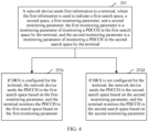
- the terminal may include a receiving unit 701 and a processing unit 702.
- the receiving unit 701 is configured to receive first information sent by a network device.
- the first information is used to indicate a first search space, a second search space, a first monitoring parameter, and a second monitoring parameter.
- the first monitoring parameter is a monitoring parameter for monitoring a PDCCH in the first search space by the terminal.
- the second monitoring parameter is a monitoring parameter for monitoring a PDCCH in the second search space by the terminal.
- the first search space is different from the second search space.
- the first search space is the same as the second search space but the first monitoring parameter is different from the second monitoring parameter.
- the processing unit 702 is configured to: monitor the PDCCH in the first search space based on the first monitoring parameter, or monitor, by the terminal, the PDCCH in the second search space based on the second monitoring parameter.
- the receiving unit 701 is further configured to receive second information sent by the network device.
- the second information is used to instruct the terminal to monitor the PDCCH in the first search space based on the first monitoring parameter, or the second information is used to instruct the terminal to monitor the PDCCH in the second search space based on the second monitoring parameter.
- the second information is sent to the terminal by using DCI, a MAC CE, or RRC signaling.
- the receiving unit 701 is further configured to receive third information sent by the network device.
- the third information is used to indicate a working mode of the terminal.
- the third information is sent to the terminal by using DCI, a MAC CE, or RRC signaling.
- the processing unit 702 is specifically configured to: when DRX is configured for the terminal, monitor the PDCCH in the first search space based on the first monitoring parameter; or when DRX is not configured for the terminal, monitor the PDCCH in the second search space based on the second monitoring parameter.
- the processing unit 702 is specifically configured to: when a first DRX parameter is configured for the terminal, monitor the PDCCH in the first search space based on the first monitoring parameter; or when a second DRX parameter is configured for the terminal, monitor the PDCCH in the second search space based on the second monitoring parameter.
- the monitoring parameter includes one or more of the following parameters: a format of monitored DCI, a monitoring periodicity, a monitoring slot, monitoring duration in a to-be-monitored slot, a monitoring start symbol in a to-be-monitored slot, an aggregation level of a monitored PDCCH, and a quantity of PDCCH candidate locations that need to be monitored at the aggregation level.
- the terminal may further include a sending unit 703, configured to send indication information used to indicate the working mode of the terminal.
- an embodiment of this application further provides a network device, to implement functions of the network device in the foregoing method embodiments.
- the network device may include a sending unit 801 and a processing unit 802.
- the processing unit 802 is configured to use the sending unit 801 to: send the PDCCH in the first search space based on the first monitoring parameter, or send the PDCCH in the second search space based on the second monitoring parameter.
- the sending unit 801 is further configured to send second information to the terminal.
- the second information is used to instruct the terminal to monitor the PDCCH in the first search space based on the first monitoring parameter, or the second information is used to instruct the terminal to monitor the PDCCH in the second search space based on the second monitoring parameter.
- the second information is sent to the terminal by using DCI, a MAC CE, or RRC signaling.
- the processing unit 802 is specifically configured to: when it is determined that the terminal is in a first working mode, send the PDCCH in the first search space based on the first monitoring parameter by using the sending unit 801; or when it is determined that the terminal is in a second working mode, send the PDCCH in the second search space based on the second monitoring parameter by using the sending unit 801.
- the sending unit 801 is further configured to send third information to the terminal.
- the third information is used to indicate a working mode of the terminal.
- the third information is sent to the terminal by using DCI, a MAC CE, or RRC signaling.
- the processing unit 802 is specifically configured to: when it is determined that discontinuous reception DRX is configured for the terminal, send the PDCCH in the first search space based on the first monitoring parameter by using the sending unit 801; or when it is determined that DRX is not configured for the terminal, send the PDCCH in the second search space based on the second monitoring parameter by using the sending unit 801.
- the processing unit 802 is specifically configured to: when it is determined that a first DRX parameter is configured for the terminal, send the PDCCH in the first search space based on the first monitoring parameter by using the sending unit 801; or when it is determined that a second DRX parameter is configured for the terminal, send the PDCCH in the second search space based on the second monitoring parameter by using the sending unit 801.
- the monitoring parameter includes one or more of the following parameters: a format of monitored DCI, a monitoring periodicity, a monitoring slot, monitoring duration in a to-be-monitored periodicity, a monitoring start symbol in a to-be-monitored slot, an aggregation level of a monitored PDCCH, and a quantity of PDCCH candidate locations that need to be monitored at the aggregation level.
- the network device may further include a receiving unit 803, configured to receive indication information that is used to indicate the working mode of the terminal and that is sent by the terminal.
- division of the foregoing units is merely logical function division. In actual implementation, all or some of the units may be integrated into one physical entity, or may be physically separate. In addition, these units may all be implemented in a form of software invoked by using a processing element, or may all be implemented in a form of hardware; or some units may be implemented in a form of software invoked by using a processing element, and some units are implemented in a form of hardware.
- the receiving unit and the sending unit may be separately disposed, or may be combined into a transceiver unit.
- the transceiver unit and the processing unit may be integrated, or may be separately implemented.
- the processing element may be an integrated circuit and has a signal processing capability.
- steps in the foregoing methods or the foregoing units can be implemented by using a hardware integrated logical circuit in the processing element, or by using instructions in a form of software.
- the foregoing sending unit is a unit for controlling sending, and may send information by using sending apparatuses such as an antenna and a radio frequency apparatus.
- the receiving unit may alternatively receive information by using receiving apparatuses such as an antenna and a radio frequency apparatus.
- the foregoing units may be configured as one or more integrated circuits for implementing the foregoing method, for example, one or more application-specific integrated circuits (application-specific integrated circuit, ASIC), one or more microprocessors, or one or more field programmable gate arrays (field programmable gate array, FPGA).
- ASIC application-specific integrated circuit
- microprocessors microprocessors
- field programmable gate array field programmable gate array
- FPGA field programmable gate array
- the processing element may be a general purpose processor, for example, a central processing unit (central processing unit, CPU) or another processor that can invoke the program.
- CPU central processing unit
- these units may be integrated together, and are implemented in a form of a system-on-a-chip (system-on-a-chip, SOC).
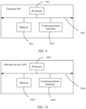
- the terminal 900 may include a processor 901, a memory 902, and a communications interface 903. Further, the terminal 900 may further include a communications bus 904.
- the processor 901 may be a general purpose CPU, a microprocessor, an ASIC, or one or more integrated circuits configured to control program execution in the solutions of this application.
- the communications bus 904 may include a path to transmit information between the foregoing components.
- the memory 902 may be a read-only memory (read-only memory, ROM), a static storage device in another type that can store static information and an instruction, a random access memory (random access memory, RAM), or a dynamic storage device in another type that can store information and an instruction; or may be an electrically erasable programmable read-only memory (electrically erasable programmable read-only memory, EEPROM), a compact disc read-only memory (compact disc read-only memory, CD-ROM), or another compact disc storage or optical disc storage (including a compact disc, a laser disc, an optical disc, a digital versatile disc, a Blu-ray disc, and the like), a magnetic disk storage medium, another magnetic storage device, or any other medium that can be used to carry or store desired program code in a form of an instruction or a data structure and that is accessible to a computer.
- the memory 902 is not limited thereto.
- the memory 902 may exist independently, and is connected to the processor 901 by using a bus. Alternatively,
- the memory 902 is configured to store application program code used for executing the solutions of this application, and the processor 901 controls the execution.
- the processor 901 is configured to execute the application program code stored in the memory 902, to implement the communication method in the foregoing embodiments of this application.
- the processor 901 may implement related functions in the communication method provided in the foregoing embodiments of this application.
- the communications interface 903 is responsible for communicating with another device or a communications network. This is not specifically limited in this embodiment of this application.
- the processor 901 may include one or more CPUs.
- the terminal may include a plurality of processors.
- Each of the processors may be a single-core (single-CPU) processor, or may be a multi-core (multi-CPU) processor.
- the processor herein may be one or more devices, circuits, and/or processing cores for processing data (such as a computer program instruction).
- the processor 901 is further configured to receive, by using the communications interface 903, the second information sent by the network device.
- the second information is used to instruct the terminal to monitor the PDCCH in the first search space based on the first monitoring parameter, or the second information is used to instruct the terminal to monitor the PDCCH in the second search space based on the second monitoring parameter.
- the second information is sent to the terminal by using downlink control information DCI, a media access control control element MAC CE, or radio resource control RRC signaling.
- the processor 901 is specifically configured to: when the terminal is in a first working mode, monitor the PDCCH in the first search space based on the first monitoring parameter by using the communications interface 903; or when the terminal is in a second working mode, monitor the PDCCH in the second search space based on the second monitoring parameter by using the communications interface 903.
- the processor 901 is further configured to receive, by using the communications interface 903, third information sent by the network device.
- the third information is used to indicate a working mode of the terminal.
- the third information is sent to the terminal by using DCI, a MAC CE, or RRC signaling.
- the processor 901 is specifically configured to: when discontinuous reception DRX is configured for the terminal, monitor the PDCCH in the first search space based on the first monitoring parameter by using the communications interface 903; or when DRX is not configured for the terminal, monitor the PDCCH in the second search space based on the second monitoring parameter by using the communications interface 903.
- the processor 901 is specifically configured to: when a first DRX parameter is configured for the terminal, monitor the PDCCH in the first search space based on the first monitoring parameter by using the communications interface 903; or when a second DRX parameter is configured for the terminal, monitor the PDCCH in the second search space based on the second monitoring parameter by using the communications interface 903.
- the monitoring parameter includes one or more of the following parameters: a format of monitored DCI, a monitoring periodicity, a monitoring slot, monitoring duration in a to-be-monitored slot, a monitoring start symbol in a to-be-monitored slot, an aggregation level of a monitored PDCCH, and a quantity of PDCCH candidate locations that need to be monitored at the aggregation level.
- the processor 1001 may be a general purpose CPU, a microprocessor, an ASIC, or one or more integrated circuits configured to control program execution in the solutions of this application.
- the communications bus 1004 may include a path to transmit information between the foregoing components.
- the communications interface 1003 uses any apparatus such as a transceiver, and is configured to communicate with another device or a communications network, such as Ethernet, a radio access network (radio access network, RAN), or a wireless local area network (wireless local area networks, WLAN).
- a communications network such as Ethernet, a radio access network (radio access network, RAN), or a wireless local area network (wireless local area networks, WLAN).
- the memory 1002 is configured to store application program code used for executing the solutions of this application, and the processor 1001 controls the execution.
- the processor 1001 is configured to execute the application program code stored in the memory 1002, to implement the communication method in the foregoing embodiments of this application.
- the processor 1001 may implement related functions in the communication method provided in the foregoing embodiments of this application.
- the communications interface 1003 is responsible for communicating with another device or a communications network. This is not specifically limited in this embodiment of this application.
- the processor 1001 may include one or more CPUs.
- the network device may include a plurality of processors.
- Each of the processors may be a single-core (single-CPU) processor, or may be a multi-core (multi-CPU) processor.
- the processor herein may be one or more devices, circuits, and/or processing cores for processing data (such as a computer program instruction).
- the processor 1001 is further configured to send second information to the terminal by using the communications interface 1003.
- the second information is used to instruct the terminal to monitor the PDCCH in the first search space based on the first monitoring parameter, or the second information is used to instruct the terminal to monitor the PDCCH in the second search space based on the second monitoring parameter.
- the second information is sent to the terminal by using downlink control information DCI, a media access control control element MAC CE, or radio resource control RRC signaling.
- the processor 1001 is specifically configured to: when it is determined that discontinuous reception DRX is configured for the terminal, send the PDCCH in the first search space based on the first monitoring parameter by using the communications interface 1003; or when it is determined that DRX is not configured for the terminal, send the PDCCH in the second search space based on the second monitoring parameter by using the communications interface 1003.
- an embodiment of this application further provides a communications system, including the foregoing terminal and the foregoing network device.
- An embodiment of this application provides a computer readable storage medium.
- the computer readable storage medium stores a computer instruction.
- the instruction When the instruction is run on a computer, the computer is enabled to implement functions implemented by the terminal in the foregoing method embodiments.
- An embodiment of this application provides a computer readable storage medium.
- the computer readable storage medium stores a computer instruction.
- the instruction When the instruction is run on a computer, the computer is enabled to implement functions implemented by the network device in the foregoing method embodiments.
- An embodiment of this application provides a computer program product including an instruction.
- the computer program product When the computer program product is run on the computer, the computer is enabled to implement functions implemented by the terminal in the foregoing method embodiments.
- An embodiment of this application provides a computer program product including an instruction.
- the computer program product When the computer program product is run on the computer, the computer is enabled to implement functions implemented by the network device in the foregoing method embodiments.
- An embodiment of this application provides a chip.
- the chip is connected to a memory, and is configured to read and execute a software program stored in the memory, to implement functions implemented by the terminal in the foregoing method embodiments.
- An embodiment of this application provides a chip.
- the chip is connected to a memory, and is configured to read and execute a software program stored in the memory, to implement functions implemented by the network device in the foregoing method embodiments.
Description
- This application relates to the field of communications technologies, and in particular, to communication methods and devices.
- Abase station sends downlink control information (downlink control information, DCI) to a terminal by using a physical downlink control channel (physical downlink control channel, PDCCH), to indicate configuration parameters such as a time-frequency resource on which the terminal receives downlink data, a modulation and coding scheme (modulation and coding scheme, MCS), and a redundancy version (redundancy version, RV).
- When the terminal receives the DCI, blind detection (blind detect, BD) is performed at a plurality of PDCCH candidate locations in a downlink control region. A group of PDCCH candidate locations form a search space (search space). The base station may configure one or more search spaces for the terminal. The terminal performs monitoring in the configured one or more search spaces, to detect whether there is DCI sent to the terminal. The base station further configures, for the terminal, a parameter for monitoring the PDCCH in each search space, for example, a monitoring periodicity, a monitoring slot, an aggregation level of the PDCCH, and a maximum quantity of blind detection times.
- In the prior art, the base station may send, to the terminal by using radio resource control (radio resource control, RRC) signaling, the one or more search spaces configured for the terminal and a monitoring parameter corresponding to each search space, and the terminal monitors the PDCCH in a corresponding search space based on the received monitoring parameter. However, when configuring the search space and the monitoring parameter for the terminal, the base station determines only the search space and the monitoring parameter that need to be currently used by the terminal. In this case, configuration is not flexible enough.
US 2018/019844 A1 discloses a user equipment (UE). A higher-layer processor is configured to configure a short processing time. A PDCCH receiver is configured to receive, in a subframe n, a PDCCH. A physical downlink shared channel (PDSCH) receiver is configured to receive, in the subframe n, a PDSCH corresponding to the PDCCH. An uplink receiver is configured to feedback, in a subframe n+k, a hybrid automatic repeat request-acknowledgement (HARQ-ACK) corresponding to the PDSCH. In a case that the PDCCH is a PDCCH in common search space, the k is equal to k1. In a case that the PDCCH is a PDCCH in UE-specific search space, the k is equal to k2. The k2 is smaller than the k1.
US 2017/332377 A1 discloses facilitation detection of control channels with different transmission time intervals (TTIs) in wireless communications systems. In one example, a computer-implemented method comprises: monitoring, by a mobile device comprising a processor, a first control channel in the beginning of a first TTI; and receiving, by the mobile device, a first downlink control information (DCI) on the first control channel in the first TTI, wherein information of the first DCI indicates a pattern of a second TTI associated with a second control channel, and wherein the second control channel occurs later than the first control channel and the second TTI is shorter than the first TTI. The computer-implemented method can also comprise determining, by the mobile device, whether to monitor the second control channel of the second TTI based on the information of the first DCI. - This application provides communication methods and devices to send one or more groups of search spaces and a plurality of groups of PDCCH monitoring parameters to a terminal, so that the terminal monitors a PDCCH in one group of search spaces based on one group of monitoring parameters. The technical solution is as defined in accordance with the appended claims. Aspects or embodiments of the disclosure which do not fall under the scope of the claims are not included in the scope of the invention.
-
-
FIG. 1 is a schematic diagram of an application scenario; -
FIG. 2 is a schematic flowchart 1 of a communication method; -
FIG. 3 is a schematic flowchart 2 of a communication method; -
FIG. 4 is a schematic flowchart 3 of a communication method; -
FIG. 5 is a schematic diagram of DRX; -
FIG. 6 is a schematic flowchart 4 of a communication method; -
FIG. 7 is a schematic structural diagram 1 of a terminal; -
FIG. 8 is a schematic structural diagram 1 of a network device; -
FIG. 9 is a schematic structural diagram 2 of a terminal; and -
FIG. 10 is a schematic structural diagram 2 of a network device; - To make the objectives, technical solutions, and advantages of this application clearer, the following further describes this application in detail with reference to the accompanying drawings.
- A base station may send, to a terminal by using RRC signaling, one or more search spaces configured for the terminal and a monitoring parameter corresponding to each search space. The terminal monitors a PDCCH in a corresponding search space based on the received monitoring parameter. However, when configuring the search space and the monitoring parameter for the terminal, the base station determines only the search space and the monitoring parameter that need to be currently used by the terminal. In this case, configuration is not flexible enough.
- To implement more flexible configuration, the embodiments of this application provide a communication method and a communications apparatus. The method and the apparatus may be applied to a 5th generation (the 5th generation, 5G) mobile communications system, a long term evolution (long term evolution, LTE) system, or another communications system. The embodiments of this application may be applied to a scenario shown in
FIG. 1 . - When a network device in the embodiments of this application is a base station, the base station may be configured to mutually convert a received over-the-air frame and an Internet protocol (Internet Protocol, IP) packet and serve as a router between a wireless terminal and a rest portion of an access network, where the rest portion of the access network may include an IP network. The network device may be further configured to coordinate attribute management of the air interface. In communications systems using different radio access technologies, devices having a base station function may have different names. For example, a base station in a global system for mobile communications (global system for mobile communications, GSM) or a code division multiple access (code division multiple access, CDMA) system is referred to as a base transceiver station (base transceiver station, BTS); a base station in a wideband code division multiple access (wideband code division multiple access, WCDMA) system is referred to as a nodeB (nodeB); a base station in an LTE system is referred to as an evolved nodeB (evolutional nodeB, eNB); a base station in an NR system is referred to as a general nodeB (general nodeB, gNB). This is not limited in the embodiments of this application.
- The terminal device in the embodiments of this application may also be referred to as user equipment (user equipment, UE), an access terminal device, a subscriber unit, a subscriber station, a mobile station, a mobile console, a remote station, a remote terminal device, a mobile device, a user terminal device, a terminal device, a wireless communication device, a user agent, a user apparatus, or the like. The terminal device may be a cellular phone, a cordless phone, a session initiation protocol (session initiation protocol, SIP) phone, a wireless local loop (wireless local loop, WLL) station, a personal digital assistant (personal digital assistant, PDA), a handheld device having a wireless communication function, a computing device, another processing device connected to a wireless modem, a vehicle-mounted device, a wearable device, a terminal device in a future 5G network, or a terminal device in a future evolved public land mobile network (public land mobile network, PLMN). This is not limited in the embodiments of this application.
-
FIG. 2 is a schematic flowchart of a communication method according to an embodiment of this application. As shown in the figure, the method may include the following steps. - Step 201: A network device sends first information to a terminal. The first information is used to indicate a first search space, a second space, a first monitoring parameter, and a second monitoring parameter. The first monitoring parameter is a monitoring parameter for monitoring a PDCCH in the first search space by the terminal. The second monitoring parameter is a monitoring parameter for monitoring a PDCCH in the second search space by the terminal.
- The first search space and the second search space may be a same search space but the first monitoring parameter is different from the second monitoring parameter. In other words, the terminal may monitor a PDCCH in a same search space based on different monitoring parameters in different duration, different working modes, and different scenarios. Alternatively, the first search space and the second search space may be different search spaces but the first monitoring parameter may be the same as the second monitoring parameter. In other words, the terminal may monitor a PDCCH in different search spaces based on a same monitoring parameter in different duration, different working modes, and different scenarios. Alternatively, the first search space is different from the second search space and the first monitoring parameter is also different from the second monitoring parameter. In other words, the terminal may monitor a PDCCH in different search spaces based on monitoring parameters of the search spaces in different duration, different working modes, and different scenarios.
- Step 202: The network device sends the PDCCH in the first search space based on the first monitoring parameter, and the terminal monitors the PDCCH in the first search space based on the first monitoring parameter; or the network device sends the PDCCH in the second search space based on the second monitoring parameter, and the terminal monitors the PDCCH in the second search space based on the second monitoring parameter.
- In a conventional PDCCH monitoring process, the network device sends a search space and a corresponding monitoring parameter to the terminal, and the terminal performs monitoring in all search spaces indicated by the network device. If the search space or the monitoring parameter needs to be changed, the network device needs to send a changed search space and all monitoring parameters to the terminal. However, in the foregoing method, the first information sent by the network device may carry a plurality of groups of search spaces and a plurality of groups of monitoring parameters, and the terminal monitors the PDCCH in one group of search spaces based on corresponding monitoring parameters instead of monitoring the PDCCH in all the search spaces. If the search space or the monitoring parameter needs to be changed, instead of sending the search space and all the monitoring parameters, the network device only needs to instruct the terminal to switch the search space or the monitoring parameter.
- It should be understood that, that the first information described in the foregoing embodiment includes the first search space, the second search space, the first monitoring parameter, and the second monitoring parameter does not indicate that the first information includes only these pieces of information. The first information may further include a third search space, a third monitoring parameter, and the like.
- If the first information further includes the third search space and the third monitoring parameter, the network device may further indicate that the third search space and the third monitoring parameter belong to a same first monitoring group as the first search space and the first monitoring parameter. In other words, in same duration, the terminal may monitor the PDCCH in the first search space based on the first monitoring parameter, and may also monitor the PDCCH in the third search space based on the third monitoring parameter. Alternatively, the network device may indicate that the third search space and the third monitoring parameter belong to a same second monitoring group as the second search space and the second monitoring parameter. In other words, in same duration, the terminal may monitor the PDCCH in the second search space based on the second monitoring parameter, and may also monitor the PDCCH in the third search space based on the third monitoring parameter. Alternatively, the network device may indicate that the third search space and the third monitoring parameter belong to a third monitoring group. In other words, when the terminal monitors the PDCCH in the third search space based on the third monitoring parameter, the terminal does not monitor the PDCCH in the first search space based on the first monitoring parameter, and also does not monitor the PDCCH in the second search space based on the second monitoring parameter.
- Optionally, the foregoing monitoring parameter may include one of or a combination of the following parameters:
Format of monitored DCI (DCI format): The DCI transmitted by the network device by using the PDCCH has a plurality of formats. Different formats are used based on different purposes and scenarios. For example, DCI used to schedule a physical uplink shared channel (physical uplink shared channel, PUSCH) may have a format different from DCI used to schedule a physical downlink shared channel (physical downlink shared channel, PDSCH). The network device may instruct the terminal to monitor DCI in one or more formats in a corresponding search space. For example, a format of DCI that the network device may instruct the terminal to monitor in the first search space is DCI-format0-0-AndFormat1-0, DCI-format2-0, DCI-format2-1, DCI-format2-2, or DCI-format2-3; and a format of DCI that the network device may instruct the terminal to monitor in the second search space is DCI-format0-0-AndFormat1-0, or DCI-format2-0. - Monitoring periodicity: The network device may configure a monitoring periodicity for the terminal, to instruct the terminal to monitor a PDCCH in a search space based on the monitoring periodicity. The monitoring periodicity may be in a unit of a slot. For example, if the monitoring periodicity indicated by the network device is 8, it indicates that the monitoring periodicity is eight slots. Certainly, the unit of the monitoring periodicity is not limited to a slot, and may alternatively be millisecond (ms), a subframe, or the like.
- Monitoring slot: The monitoring slot is used to indicate a slot in which the terminal monitors a PDCCH. Generally, the terminal monitors one slot in one monitoring periodicity. For example, if the network device may indicate that the monitoring periodicity is 10 slots, the monitoring slot is a slot 0. Certainly, the terminal may also monitor a plurality of slots in one monitoring periodicity. If the plurality of monitored slots are consecutive slots, a monitoring slot parameter may further include a monitoring start slot and monitoring duration. The monitoring start slot indicates a slot from which the terminal starts to perform monitoring in one monitoring periodicity, and the monitoring duration indicates a quantity of continuously monitored slots in one monitoring periodicity. Alternatively, the network device may indicate, by using a bitmap, specified slots in which monitoring is performed in one monitoring periodicity. To be specific, each bit corresponds to one slot in the monitoring periodicity, and a value of the bit indicates whether to monitor the slot. The bit map is used to instruct the terminal to monitor one slot, a plurality of consecutive slots, or a plurality of inconsecutive slots in one monitoring periodicity. Certainly, a time unit indicated by the network device may alternatively be millisecond (ms), a subframe, or the like. In this case, the network device may alternatively send parameters such as a monitoring time (ms) and a monitoring subframe.
- Generally, the two parameters: the monitoring periodicity and the monitoring slot are sent together to the terminal for use, and are sent to the terminal by using a "monitoring slot periodicity and offset (monitoringSlotPeriodicityAndOffset)" parameter.
- Monitoring duration (duration) in a to-be-monitored slot: The duration is used to indicate duration of monitoring performed by the terminal in a slot that needs to be monitored. A unit of the duration may be a symbol.
- Monitoring start symbol in a to-be-monitored slot (monitoringSymbolsWithinSlot): The symbol is used to indicate a start symbol of monitoring a PDCCH by the terminal in a slot that needs to be monitored. For example, one slot includes 14 symbols that respectively correspond to 14 bits. If a value of the 14 bits is 10000001000000, it indicates that the terminal starts to monitor a PDCCH from a symbol 0 and a symbol 7 in one to-be-monitored slot. Further, if a value of duration is 3, that is, one time of monitoring lasts for three symbols, the terminal monitors a PDCCH on a symbol 0, a symbol 1, a symbol 2, a symbol 7, a symbol 8, and a symbol 9.
- Aggregation level of a monitored PDCCH and a quantity (nrofCandidates) of PDCCH candidate locations that need to be monitored at the aggregation level:
The aggregation level (aggregationLevelx) indicates a quantity of control channel elements (control channel element, CCE) included in one PDCCH. If one PDCCH includes one CCE, an aggregation level of the PDCCH is 1; if one PDCCH includes two CCEs, an aggregation level of the PDCCH is 2; and so on. Common aggregation levels are 1, 2, 4, 8, and 16. - The quantity of monitored PDCCH candidate locations indicates a maximum quantity of PDCCH candidate locations monitored in a search space by the terminal. For example, if one search space includes eight CCEs, for a PDCCH whose aggregation level is 1, there are eight PDCCH candidate locations. If a quantity that is of monitored PDCCH candidate locations and that is indicated by the network device is 6, it indicates that the terminal selects, according to a preset rule, six PDCCH candidate locations from the eight PDCCH candidate locations for monitoring.
- Type of a search space (searchSpaceType): The type is used to indicate whether a search space indicated by the network device is a common search space (common) or a user equipment-specific search space (UE-specific).
- In a possible implementation, before
step 202, the network device may further send second information to the terminal. The second information is used to instruct the terminal to monitor the PDCCH in the first search space based on the first monitoring parameter, or is used to instruct the terminal to monitor the PDCCH in the second search space based on the second monitoring parameter. In this manner, the network device determines a specified search space and a specified monitoring parameter, and instructs the terminal to monitor the PDCCH in the specified search space based on the specified monitoring parameter. - For example, the network device may preconfigure that the first search space and the first monitoring parameter correspond to an index 1, the second search space and the second monitoring parameter correspond to an index 2, and the third search space and the third monitoring parameter correspond to an index 3. If the network device determines that the terminal should monitor the PDCCH in the first search space based on the first monitoring parameter, and determines that the network device sends the PDCCH in the first search space based on the first monitoring parameter, the second information sent by the network device may include indication information of the index 1. If the network device determines that the terminal should monitor the PDCCH in the second search space based on the second monitoring parameter and monitor the PDCCH in the third search space based on the third monitoring parameter, the second information sent by the network device may include indication information of the index 2 and the index 3.
- For another example, the network device may preconfigure that the first search space, the first monitoring parameter, the third search space, and the third monitoring parameter correspond to a monitoring group 1, and the second search space and the second monitoring parameter correspond to a monitoring group 2. If the network device determines that the network device sends the PDCCH based on the monitoring parameters in the monitoring group 1 and the terminal should monitor the PDCCH based on the monitoring parameters in the monitoring group 1, the second information sent by the network device may include indication information of the monitoring group 1.
- Optionally, the network device may add the first information and the second information to same signaling, and send the signaling to the terminal. Generally, the first information is usually sent to the terminal by using RRC signaling. In this case, the network device may add the first information and the second information to the RRC signaling, and send the RRC signaling to the terminal. Certainly, the network device may alternatively send the first information and the second information to the terminal by using other signaling. This is not limited in this embodiment of this application.
- In addition, the network device may send the first information and the second information to the terminal by using different signaling. In this case, when sending the second information, the network device may send the second information to the terminal by using DCI, a MAC CE, or RRC signaling. The DCI signaling belongs to physical layer signaling, the MAC CE signaling belongs to MAC layer signaling, and the RRC signaling belongs to RRC layer signaling. When parsing the signaling, the terminal sequentially undergoes physical layer parsing, MAC layer parsing, and RRC layer parsing. Therefore, if the second information is sent by using the DCI signaling, a delay is relatively short; if the second information is sent by using the RRC signaling, a delay is relatively long; or if the second information is sent by using the MAC CE signaling, a delay is between the delay of performing sending by using the DCI signaling and the delay of performing sending by using the RRC signaling.
- Further, after
step 202, the network device may further send an indication information to the terminal when determining that the search space and the monitoring parameter for monitoring the PDCCH by the terminal need to be changed, to indicate the changed search space and the changed monitoring parameter to the terminal. Similar to the second information, the indication information may include index information of the changed search space and the changed monitoring parameter, or include index information of the changed monitoring group. The indication information may also be sent to the terminal by using DCI, a MAC CE, or RRC signaling. - In a conventional PDCCH monitoring process, if the network device determines that the search space and the monitoring parameter for the terminal need to be changed, the network device sends the changed search space and the corresponding monitoring parameter to the terminal through an RRC reconfiguration process. In this case, signaling overheads are relatively high. In the foregoing implementation, the network device has sent the plurality of possible search spaces and the corresponding monitoring parameters in the first information to the terminal. The indication information may include only the index information corresponding to the changed search space and the monitoring parameter, thereby reducing signaling overheads. In addition, if the indication information is sent by using DCI or MAC CE information, a delay is further reduced.
- In a possible implementation, step S202 may specifically include two cases shown in
FIG. 3 :
Step 202a: If the terminal is in a first working mode, the network device sends the PDCCH in the first search space based on the first monitoring parameter, and the terminal monitors the PDCCH in the first search space based on the first monitoring parameter. -
Step 202b: If the terminal is in a second working mode, the network device sends the PDCCH in the second search space based on the second monitoring parameter, and the terminal monitors the PDCCH in the second search space based on the second monitoring parameter. - In the foregoing implementation, the network device may preconfigure that the first search space and the first monitoring parameter correspond to the first working mode, and the second search space and the second monitoring parameter correspond to the second working mode. In this case, the network device and the terminal may determine, based on a current working mode of the terminal, the search space and the monitoring parameter that are used for sending/monitoring the PDCCH.
- It should be understood that working parameters corresponding to the first working mode include the first search space and the first monitoring parameter. However, this is not limited thereto. For example, the first working mode may further be related to parameters such as a value of an operating bandwidth of the terminal, a quantity of activated carriers, and a quantity of transmit/receive antennas during multiple-antenna multiple-input multiple-output (multiple-input multiple-output, MIMO) communication. In a specific example, the network device configures that: an operating bandwidth of the terminal is 20 MHz, three carriers are activated, the terminal monitors the PDCCH in a search space 1 based on a monitoring parameter 1, and the like, when the terminal works in the first working mode; and an operating bandwidth of the terminal is 10 MHz, one carrier is activated, the terminal monitors the PDCCH in a search space 1 based on a monitoring parameter 1, and the like, when the terminal works in the second working mode. In this case, when the terminal determines to switch from the first working mode to the second working mode, the terminal monitors the PDCCH in a search space 2 based on a monitoring parameter 2, the working bandwidth is switched from 20 MHz to 10 MHz, and three activated carriers is changed to one activated carrier. Certainly, various parameters configured by the network device may be sent to the terminal by using a same piece of signaling or a plurality of pieces of signaling.
- In some embodiments, the network device may send a third information to the terminal. The third information is used to indicate a working mode of the terminal. Specifically, a working mode switching policy of the terminal may be preconfigured in the network device. The network device may determine the current working mode of the terminal based on factors such as the working mode switching policy, a current network environment, a status of the terminal, and a requirement of the terminal; and send, to the terminal, the third information that is used to indicate the working mode of the terminal. If the third information indicates that the terminal works in the first working mode, the terminal monitors the PDCCH in the first search space based on the first monitoring parameter. Correspondingly, after sending the third information, the network device sends the PDCCH in the first search space based on the first monitoring parameter. If the third information indicates that the terminal works in the second working mode, the terminal monitors the PDCCH in the second search space based on the second monitoring parameter. Correspondingly, after sending the third information, the network device sends the PDCCH in the second search space based on the second monitoring parameter.
- Optionally, the network device may send the third information to the terminal by using DCI, a MAC CE, or RRC signaling.
- In some other embodiments, a working mode switching policy of the terminal may be preconfigured in both the network device and the terminal. The network device and the terminal may both determine the current working mode of the terminal based on factors such as the working mode switching policy, a current network environment, a status of the terminal, and a requirement of the terminal. For example, if the network device does not send the DCI to the terminal in preset duration, the terminal and the network device may determine to switch the working mode of the terminal according to the preset working mode switching policy, to reduce a quantity of times that the terminal monitors the PDCCH. In this case, the network device may not need to send, to the terminal, a information used to indicate the working mode.
- In some other embodiments, a working mode switching policy may be preconfigured in the terminal. The terminal determines a current working mode based on factors such as the working mode switching policy, a current network environment, a status of the terminal, and a requirement of the terminal. After determining to switch the working mode, the terminal may send a fourth information to the network device, to notify the network device of a switched-to working mode, so that the network device sends a PDCCH and the terminal monitors the PDCCH in a same search space based on a same monitoring parameter. The fourth information may be sent to the network device by using uplink control information (uplink control information, UCI), a MAC CE, or RRC signaling. For example, when a quantity of electricity of the terminal decreases to a preset threshold, the terminal may switch to a power saving mode. The power saving mode corresponds to the search space 1 and the monitoring parameter 1. In this mode, a maximum quantity of times that the terminal monitors the PDCCH is less than a maximum quantity of monitoring times in another working mode. In this case, the terminal monitors the PDCCH in the search space 1 based on the monitoring parameter 1. The terminal sends the fourth information to the network device. The fourth information is used to indicate that the terminal switches to the power saving mode. Therefore, the network device sends the PDCCH in the search space 1 based on the monitoring parameter.
- Optionally, after receiving an indication information that is sent by the terminal and that is used to instruct to switch a working mode, the network device may send a response information to the terminal, to indicate whether the network device successfully switches the working mode, thereby ensuring that the terminal and the network device work in the same working mode. In this way, the following case is avoided: A information is incorrectly sent or received due to different working modes of the terminal and the network device. Specifically, the response information sent by the network device may be used to indicate whether the switching succeeds. For example, "1" is used to indicate that the switching succeeds, and "0" is used to indicate that the switching fails. Alternatively, the network device may add, to the response information, information about the working mode currently determined by the network device. For example, if the network device switches from a working mode 1 to a working mode 2, the response information carries information about the working mode 2. If the switching fails, the response information carries a information of the working mode 1. In this case, the response information is similar to the third information in the foregoing embodiment, and is used to instruct the terminal to work in the corresponding working mode based on the information about the working mode carried in the information.
- In another possible implementation, step S202 may alternatively specifically include two cases shown in
FIG. 4 :
Step 202c: If DRX is configured for the terminal, the network device sends the PDCCH in the first search space based on the first monitoring parameter, and the terminal monitors the PDCCH in the first search space based on the first monitoring parameter. -
Step 202d: If DRX is not configured for the terminal, the network device sends the PDCCH in the second search space based on the second monitoring parameter, and the terminal monitors the PDCCH in the second search space based on the second monitoring parameter. - In the foregoing implementation, the network device may preconfigure that the first search space and the first monitoring parameter correspond to a case in which DRX is configured for the terminal, and the second search space and the second monitoring parameter correspond to a case in which DRX is not configured for the terminal. In this case, the network device and the terminal may determine, based on whether DRX is currently configured for the terminal, the search space and the monitoring parameter that are used for sending/monitoring the PDCCH.
- Specifically, DRX may be configured for the terminal in an RRC_CONNECTED (RRC_connected) mode. In other words, as shown in
FIG. 5 , instead of continuously monitoring the PDCCH, the terminal monitors the PDCCH in on duration (on duration) and does not monitor the PDCCH in an opportunity for DRX (opportunity for DRX), thereby reducing power consumption of the terminal. One on duration and one opportunity for DRX form one DRX cycle. - For example, if DRX is not configured for the terminal, the terminal may monitor the PDCCH according to the monitoring periodicity in the foregoing embodiment. Because a monitoring time is relatively long, the PDCCH may be monitored by using a monitoring parameter by using which a quantity of times of monitoring the PDCCH in one monitoring periodicity is relatively small. If DRX is configured for the terminal, the PDCCH may be monitored by using a monitoring parameter by using which a quantity of times of monitoring the PDCCH in one monitoring periodicity is relatively large.
- It should be understood that, if DRX is configured for the terminal, monitoring the PDCCH in some slots in the monitoring periodicity in the foregoing embodiment means further setting a monitoring periodicity in the on duration. In other words, the terminal monitors the PDCCH in some slots in the on duration, and does not monitor the PDCCH in other slots of the on duration.
- In addition, if DRX is configured for the terminal but a configured DRX parameter changes according to different requirements in different scenarios, step 202 may alternatively specifically include two cases shown in
FIG. 6 :
Step 202e: If a first DRX parameter is configured for the terminal, the network device sends the PDCCH in the first search space based on the first monitoring parameter, and the terminal monitors the PDCCH in the first search space based on the first monitoring parameter. -
Step 202f: If a second DRX parameter is configured for the terminal, the network device sends the PDCCH in the second search space based on the second monitoring parameter, and the terminal monitors the PDCCH in the second search space based on the second monitoring parameter. - The DRX parameter may include duration of one DRX cycle, duration of on duration in one cycle, a start location of on duration in one cycle, duration of an inactivity timer (InactivityTimer), duration of a hybrid automatic repeat request (hybrid automatic repeat request, HARQ) retransmission timer (timer), and the like.
- It should be understood that the foregoing first DRX parameter and the foregoing second DRX parameter may separately include one or more parameters. In other words, the first DRX parameter and the second DRX parameter may be used to indicate parameter groups.
- In the foregoing implementation, the network device may preconfigure that the first search space and the first monitoring parameter correspond to the first DRX parameter, and the second search space and the second monitoring parameter correspond to the second DRX parameter. In this case, the network device and the terminal may determine, based on the DRX parameter configured for the terminal, the search space and the monitoring parameter that are used for sending/monitoring the PDCCH.
- To further clearly explain the foregoing embodiment of this application, the following provides description by using examples.
- In a conventional process of configuring a search space and a monitoring parameter of a PDCCH, the network device may send RRC signaling to the terminal. The signaling may include a list of to-be-added search spaces (searchSpacesToAddModList) and a list of to-be-deleted search spaces (searchSpacesToReleaseList) to indicate a search space of the PDCCH of the terminal.
- To reduce changes to an existing solution, the foregoing parameters may still be used to indicate the first search space of the terminal, and an index corresponding to the first search space may be normal (normal). In addition, a new parameter: a list of search spaces for power saving (searchSpacesForPowerSavingToAddModList) is added to indicate the second search space. An index corresponding to the second search space may be power saving (powerSaving).
- The network device may further add a new parameter (usage) to the foregoing information. A value of the parameter may indicate normal or powerSaving, that is, the parameter is used to indicate whether the terminal monitors the PDCCH by using the first search space or by using the second search space. The parameter may also be default. If the parameter is default, the terminal uses a default value: normal. Alternatively, the network device may send, to the terminal by using DCI, a MAC CE, or RRC signaling, an indication information including the foregoing parameter (usage).
- Then, if the network device determines to change the PDCCH monitored by the terminal, the network device may send, to the terminal by using DCI, a MAC CE, or RRC signaling, the indication information including the foregoing parameter (usage), to indicate a changed search space to the terminal.
- In a conventional process of configuring a search space and a monitoring parameter of a PDCCH, the network device may send RRC signaling to the terminal. The signaling may include a monitoring slot periodicity and offset (monitoringSlotPeriodicityAndOffset), a monitoring start symbol in a to-be-monitored slot (monitoringSymbolsWithinSlot), monitoring duration (duration) in a to-be-monitored slot, an aggregation level of a monitored PDCCH, and a quantity (nrofCandidates) of PDCCH candidate locations that need to be monitored at the aggregation level.
- To reduce changes to an existing solution, the foregoing parameters may still be used to indicate the first monitoring parameter to the terminal, and an index corresponding to the first monitoring parameter may be normal (normal). Specifically, the monitoring periodicity is two slots, the monitoring slot is a slot 0, monitoring starts from a symbol 0 and a symbol 7 in the to-be-monitored slot, and monitoring lasts for three symbols. In other words, the terminal monitors the PDCCH on the symbol 0, a symbol 1, a symbol 2, the symbol 7, a symbol 8, and a symbol 9. The aggregation level of the monitored PDCCH and the quantity (nrofCandidates) of PDCCH candidate locations that need to be monitored at the aggregation level may be shown in Table 1.
Table 1 Aggregation level 1 8 Aggregation level 2 8 Aggregation level 4 6 Aggregation level 8 4 Aggregation level 16 2 - In addition, a new parameter: a monitoring slot periodicity and offset for power saving (monitoringSlotPeriodicityAndOffsetForPowerSaving) is added, to indicate that the monitoring periodicity is 10 slots and monitoring is performed on the slot 0; and new parameters: a monitoring start symbol in a to-be-monitored slot for power saving (monitoringSymbolsWithinSlot ForPowerSaving) and monitoring duration in a to-be-monitored slot for power saving (durationForPowerSaving) are added, to indicate that monitoring is performed on a symbol 0, a symbol 1, and a symbol 2 in one to-be-monitored slot. The aggregation level of the monitored PDCCH and the quantity (nrofCandidates) of PDCCH candidate locations that need to be monitored at the aggregation level are shown in Table 2.
Table 2 Aggregation level 1 4 Aggregation level 2 4 Aggregation level 4 3 Aggregation level 8 2 Aggregation level 16 1 - It may be learned from Table 1 that, in a to-be-monitored slot, a maximum quantity of blind detection times is 8+8+6+4+2=28. It may be learned from the first monitoring parameter that, in 10 slots (five monitoring periodicities), a maximum quantity of blind detection times of the terminal is 28*5=140. It may be learned from Table 2 that, in a to-be-monitored slot, a maximum quantity of blind detection times is 4+4+3+2+1=14. It may be learned from the second monitoring parameter that, in 10 slots (one monitoring periodicity), a maximum quantity of blind detection times of the terminal is 10. Therefore, when the terminal uses the second monitoring parameter, a time required for monitoring the PDCCH is shorter, thereby reducing power consumption of the terminal.
- The network device may further add a new parameter (usage). A value of the parameter may indicate normal or powerSaving, that is, the parameter is used to indicate whether the terminal uses the first monitoring parameter or uses the second monitoring parameter. The parameter may also be default. If the parameter is default, the terminal uses a default value: normal.
- Then, if the network device determines to change the PDCCH monitored by the terminal, the network device may send, to the terminal by using DCI, a MAC CE, or RRC signaling, an indication information including the foregoing parameter (usage).
- The terminal may have two working modes: a normal working mode (normal mode) and a power saving mode (power saving mode). Each search space corresponds to one working mode. For example, the search space 1 and the monitoring parameter 1 correspond to a middle-class working mode, and the search space 2 and the monitoring parameter 2 correspond to a power-saving working mode. Information that is of the search space and the monitoring parameter and that is sent by the network device to the terminal is similar to that in Embodiments 1 and 2. Details are not described herein again.
- The network device may send DCI, a MAC CE, or RRC signaling to the terminal. The signaling includes a working mode parameter (mode). A value of the parameter may indicate the normal working mode or the power saving working mode, to indicate the working mode of the terminal.
- In this embodiment, the working mode that is of the terminal and that is indicated by the network device is not merely used to indicate the search space and the monitoring parameter for monitoring the PDCCH by the terminal, and may be further used to indicate a value of an operating bandwidth of the terminal, a quantity of activated carriers, and the like.
- The network device may configure a group of a search space and a monitoring parameter for the terminal to be used by the terminal to monitor the PDCCH when DRX is not configured for the terminal. The network device may further configure another group of a search space and a monitoring parameter for the terminal to be used by the terminal to monitor the PDCCH when DRX is configured for the terminal.
- The network device may send signaling such as DCI, a MAC CE, or RRC signaling to the terminal. The signaling may include a parameter indicating whether DRX is configured for the terminal. In addition, the signaling may further carry a DRX configuration parameter, for example, a DRX cycle or duration of on duration.
- The network device may configure the search space 1 and the monitoring parameter 1 for the terminal to be used by the terminal to monitor the PDCCH when a DRX cycle of is less than 50 ms. The network device may further configure the search space 2 and the monitoring parameter 2 for the terminal to be used by the terminal to monitor the PDCCH when a DRX cycle is greater than or equal to 50 ms. Information that is of the search space and the monitoring parameter and that is sent by the network device to the terminal is similar to that in Embodiments 1 and 2. Details are not described herein again.
- The network device may send signaling such as DCI, a MAC CE, or RRC signaling to the terminal. The signaling may include a DRX parameter configured for the terminal. The DRX parameter includes a DRX cycle and the like. The terminal and the network device may determine to use the first group of the search space and the monitoring parameter or the second group of the search space and the monitoring parameter based on the DRX parameter.
- The network device may configure the search space 1 and the monitoring parameter 1 for the terminal. The monitoring parameter 1 includes a DCI format parameter that indicates a format of DCI for monitoring performed by the terminal is DCI-format0-0-AndFormat1-0, DCI-format2-0, DCI-format2-1, DCI-format2-2, or DCI-format2-3. The network device may further configure the search space 2 and the monitoring parameter 2 for the terminal. The monitoring parameter 2 also includes a DCI format parameter that indicates a format of DCI for monitoring performed by the terminal is DCI-format0-0-AndFormat1-0, or DCI-format2-0.
- The foregoing DCI formats are merely examples. The format that is of DCI for monitoring performed by the terminal and that is indicated by the network device may be a DCI format in a 5G system, a DCI format in an LTE system, or another future DCI format. For example, some future DCI formats may further indicate whether the terminal is inactive for a period of time, how long the terminal wakes up from an inactive state, and the like.
- Information that is of the search space and the monitoring parameter and that is sent by the network device to the terminal is similar to that in Embodiments 1 and 2. Details are not described herein again.
- It should be understood that the name of the search space list, the name of the search space index, the parameter name, the name of the DCI format, and the like added in the foregoing specific embodiments are all examples and do not constitute limitation on this embodiment of this application.
- Based on a same technical concept, an embodiment of this application further provides a terminal, to implement functions of the terminal in the foregoing method embodiments. As shown in
FIG. 7 , the terminal may include a receivingunit 701 and aprocessing unit 702. - The receiving
unit 701 is configured to receive first information sent by a network device. The first information is used to indicate a first search space, a second search space, a first monitoring parameter, and a second monitoring parameter. The first monitoring parameter is a monitoring parameter for monitoring a PDCCH in the first search space by the terminal. The second monitoring parameter is a monitoring parameter for monitoring a PDCCH in the second search space by the terminal. The first search space is different from the second search space. Alternatively, the first search space is the same as the second search space but the first monitoring parameter is different from the second monitoring parameter. - The
processing unit 702 is configured to: monitor the PDCCH in the first search space based on the first monitoring parameter, or monitor, by the terminal, the PDCCH in the second search space based on the second monitoring parameter. - In a possible implementation, the receiving
unit 701 is further configured to receive second information sent by the network device. - The second information is used to instruct the terminal to monitor the PDCCH in the first search space based on the first monitoring parameter, or the second information is used to instruct the terminal to monitor the PDCCH in the second search space based on the second monitoring parameter.
- In a possible implementation, the second information is sent to the terminal by using DCI, a MAC CE, or RRC signaling.
- In a possible implementation, the
processing unit 702 is specifically configured to: when the terminal is in a first working mode, monitor the PDCCH in the first search space based on the first monitoring parameter; or when the terminal is in a second working mode, monitor the PDCCH in the second search space based on the second monitoring parameter. - In a possible implementation, the receiving
unit 701 is further configured to receive third information sent by the network device. The third information is used to indicate a working mode of the terminal. - In a possible implementation, the third information is sent to the terminal by using DCI, a MAC CE, or RRC signaling.
- In a possible implementation, the
processing unit 702 is specifically configured to: when DRX is configured for the terminal, monitor the PDCCH in the first search space based on the first monitoring parameter; or when DRX is not configured for the terminal, monitor the PDCCH in the second search space based on the second monitoring parameter. - In a possible implementation, the
processing unit 702 is specifically configured to: when a first DRX parameter is configured for the terminal, monitor the PDCCH in the first search space based on the first monitoring parameter; or when a second DRX parameter is configured for the terminal, monitor the PDCCH in the second search space based on the second monitoring parameter. - In a possible implementation, the monitoring parameter includes one or more of the following parameters: a format of monitored DCI, a monitoring periodicity, a monitoring slot, monitoring duration in a to-be-monitored slot, a monitoring start symbol in a to-be-monitored slot, an aggregation level of a monitored PDCCH, and a quantity of PDCCH candidate locations that need to be monitored at the aggregation level.
- In a possible implementation, the terminal may further include a sending
unit 703, configured to send indication information used to indicate the working mode of the terminal. - Based on a same technical concept, an embodiment of this application further provides a network device, to implement functions of the network device in the foregoing method embodiments. As shown in
FIG. 8 , the network device may include a sendingunit 801 and aprocessing unit 802. - The sending
unit 801 is configured to send first information to a terminal. The first information is used to indicate a first search space, a second search space, a first monitoring parameter, and a second monitoring parameter. The first monitoring parameter is a monitoring parameter for monitoring a PDCCH in the first search space by the terminal. The second monitoring parameter is a monitoring parameter for monitoring a PDCCH in the second search space by the terminal. The first search space is different from the second search space. Alternatively, the first search space is the same as the second search space but the first monitoring parameter is different from the second monitoring parameter. - The
processing unit 802 is configured to use the sendingunit 801 to: send the PDCCH in the first search space based on the first monitoring parameter, or send the PDCCH in the second search space based on the second monitoring parameter. - In a possible implementation, the sending
unit 801 is further configured to send second information to the terminal. The second information is used to instruct the terminal to monitor the PDCCH in the first search space based on the first monitoring parameter, or the second information is used to instruct the terminal to monitor the PDCCH in the second search space based on the second monitoring parameter. - In a possible implementation, the second information is sent to the terminal by using DCI, a MAC CE, or RRC signaling.
- In a possible implementation, the
processing unit 802 is specifically configured to: when it is determined that the terminal is in a first working mode, send the PDCCH in the first search space based on the first monitoring parameter by using the sendingunit 801; or when it is determined that the terminal is in a second working mode, send the PDCCH in the second search space based on the second monitoring parameter by using the sendingunit 801. - In a possible implementation, the sending
unit 801 is further configured to send third information to the terminal. The third information is used to indicate a working mode of the terminal. - In a possible implementation, the third information is sent to the terminal by using DCI, a MAC CE, or RRC signaling.
- In a possible implementation, the
processing unit 802 is specifically configured to: when it is determined that discontinuous reception DRX is configured for the terminal, send the PDCCH in the first search space based on the first monitoring parameter by using the sendingunit 801; or when it is determined that DRX is not configured for the terminal, send the PDCCH in the second search space based on the second monitoring parameter by using the sendingunit 801. - In a possible implementation, the
processing unit 802 is specifically configured to: when it is determined that a first DRX parameter is configured for the terminal, send the PDCCH in the first search space based on the first monitoring parameter by using the sendingunit 801; or when it is determined that a second DRX parameter is configured for the terminal, send the PDCCH in the second search space based on the second monitoring parameter by using the sendingunit 801. - In a possible implementation, the monitoring parameter includes one or more of the following parameters: a format of monitored DCI, a monitoring periodicity, a monitoring slot, monitoring duration in a to-be-monitored periodicity, a monitoring start symbol in a to-be-monitored slot, an aggregation level of a monitored PDCCH, and a quantity of PDCCH candidate locations that need to be monitored at the aggregation level.
- In a possible implementation, the network device may further include a receiving
unit 803, configured to receive indication information that is used to indicate the working mode of the terminal and that is sent by the terminal. - It should be noted that division of the foregoing units is merely logical function division. In actual implementation, all or some of the units may be integrated into one physical entity, or may be physically separate. In addition, these units may all be implemented in a form of software invoked by using a processing element, or may all be implemented in a form of hardware; or some units may be implemented in a form of software invoked by using a processing element, and some units are implemented in a form of hardware. For example, the receiving unit and the sending unit may be separately disposed, or may be combined into a transceiver unit. In addition, the transceiver unit and the processing unit may be integrated, or may be separately implemented. The processing element may be an integrated circuit and has a signal processing capability. In an implementation process, steps in the foregoing methods or the foregoing units can be implemented by using a hardware integrated logical circuit in the processing element, or by using instructions in a form of software. In addition, the foregoing sending unit is a unit for controlling sending, and may send information by using sending apparatuses such as an antenna and a radio frequency apparatus. Likewise, the receiving unit may alternatively receive information by using receiving apparatuses such as an antenna and a radio frequency apparatus.
- The foregoing units may be configured as one or more integrated circuits for implementing the foregoing method, for example, one or more application-specific integrated circuits (application-specific integrated circuit, ASIC), one or more microprocessors, or one or more field programmable gate arrays (field programmable gate array, FPGA). For another example, when a unit in the foregoing units is implemented by scheduling a program by a processing element, the processing element may be a general purpose processor, for example, a central processing unit (central processing unit, CPU) or another processor that can invoke the program. For another example, these units may be integrated together, and are implemented in a form of a system-on-a-chip (system-on-a-chip, SOC).
- Based on a same technical concept, an embodiment of this application further provides a terminal, to implement functions of the terminal in the foregoing method embodiments. As shown in
FIG. 9 , the terminal 900 may include aprocessor 901, amemory 902, and acommunications interface 903. Further, the terminal 900 may further include acommunications bus 904. - Specifically, the
processor 901 may be a general purpose CPU, a microprocessor, an ASIC, or one or more integrated circuits configured to control program execution in the solutions of this application. - The
communications bus 904 may include a path to transmit information between the foregoing components. - The
communications interface 903 uses any apparatus such as a transceiver, and is configured to communicate with another device or a communications network, such as Ethernet, a radio access network (radio access network, RAN), or a wireless local area network (wireless local area networks, WLAN). - The
memory 902 may be a read-only memory (read-only memory, ROM), a static storage device in another type that can store static information and an instruction, a random access memory (random access memory, RAM), or a dynamic storage device in another type that can store information and an instruction; or may be an electrically erasable programmable read-only memory (electrically erasable programmable read-only memory, EEPROM), a compact disc read-only memory (compact disc read-only memory, CD-ROM), or another compact disc storage or optical disc storage (including a compact disc, a laser disc, an optical disc, a digital versatile disc, a Blu-ray disc, and the like), a magnetic disk storage medium, another magnetic storage device, or any other medium that can be used to carry or store desired program code in a form of an instruction or a data structure and that is accessible to a computer. However, thememory 902 is not limited thereto. Thememory 902 may exist independently, and is connected to theprocessor 901 by using a bus. Alternatively, thememory 902 may be integrated with theprocessor 901. - The
memory 902 is configured to store application program code used for executing the solutions of this application, and theprocessor 901 controls the execution. Theprocessor 901 is configured to execute the application program code stored in thememory 902, to implement the communication method in the foregoing embodiments of this application. - Alternatively, optionally, in this embodiment of this application, the
processor 901 may implement related functions in the communication method provided in the foregoing embodiments of this application. Thecommunications interface 903 is responsible for communicating with another device or a communications network. This is not specifically limited in this embodiment of this application. - In specific implementation, in an embodiment, the
processor 901 may include one or more CPUs. - In specific implementation, in an embodiment, the terminal may include a plurality of processors. Each of the processors may be a single-core (single-CPU) processor, or may be a multi-core (multi-CPU) processor. The processor herein may be one or more devices, circuits, and/or processing cores for processing data (such as a computer program instruction).
- Specifically, the
processor 901 may invoke a program stored in thememory 902, to perform the following steps:
Receive, by using thecommunications interface 903, first information sent by a network device. The first information is used to indicate a first search space, a second search space, a first monitoring parameter, and a second monitoring parameter. The first monitoring parameter is a monitoring parameter for monitoring a physical downlink control channel PDCCH in the first search space by the terminal. The second monitoring parameter is a monitoring parameter for monitoring a PDCCH in the second search space by the terminal. The first search space is different from the second search space. Alternatively, the first search space is the same as the second search space but the first monitoring parameter is different from the second monitoring parameter. - Use the
communications interface 903 to: monitor the PDCCH in the first search space based on the first monitoring parameter, or monitor, by the terminal, the PDCCH in the second search space based on the second monitoring parameter. - In a possible implementation, the
processor 901 is further configured to receive, by using thecommunications interface 903, the second information sent by the network device. The second information is used to instruct the terminal to monitor the PDCCH in the first search space based on the first monitoring parameter, or the second information is used to instruct the terminal to monitor the PDCCH in the second search space based on the second monitoring parameter. - In a possible implementation, the second information is sent to the terminal by using downlink control information DCI, a media access control control element MAC CE, or radio resource control RRC signaling.
- In a possible implementation, the
processor 901 is specifically configured to: when the terminal is in a first working mode, monitor the PDCCH in the first search space based on the first monitoring parameter by using thecommunications interface 903; or when the terminal is in a second working mode, monitor the PDCCH in the second search space based on the second monitoring parameter by using thecommunications interface 903. - In a possible implementation, the
processor 901 is further configured to receive, by using thecommunications interface 903, third information sent by the network device. The third information is used to indicate a working mode of the terminal. - In a possible implementation, the third information is sent to the terminal by using DCI, a MAC CE, or RRC signaling.
- In a possible implementation, the
processor 901 is specifically configured to: when discontinuous reception DRX is configured for the terminal, monitor the PDCCH in the first search space based on the first monitoring parameter by using thecommunications interface 903; or when DRX is not configured for the terminal, monitor the PDCCH in the second search space based on the second monitoring parameter by using thecommunications interface 903. - In a possible implementation, the
processor 901 is specifically configured to: when a first DRX parameter is configured for the terminal, monitor the PDCCH in the first search space based on the first monitoring parameter by using thecommunications interface 903; or when a second DRX parameter is configured for the terminal, monitor the PDCCH in the second search space based on the second monitoring parameter by using thecommunications interface 903. - In a possible implementation, the monitoring parameter includes one or more of the following parameters: a format of monitored DCI, a monitoring periodicity, a monitoring slot, monitoring duration in a to-be-monitored slot, a monitoring start symbol in a to-be-monitored slot, an aggregation level of a monitored PDCCH, and a quantity of PDCCH candidate locations that need to be monitored at the aggregation level.
- Based on a same technical concept, an embodiment of this application further provides a network device, to implement functions of the terminal in the foregoing method embodiments. As shown in
FIG. 10 , the terminal 1000 may include aprocessor 1001, amemory 1002, and acommunications interface 1003. Further, the terminal 1000 may further include acommunications bus 1004. - Specifically, the
processor 1001 may be a general purpose CPU, a microprocessor, an ASIC, or one or more integrated circuits configured to control program execution in the solutions of this application. - The
communications bus 1004 may include a path to transmit information between the foregoing components. - The
communications interface 1003 uses any apparatus such as a transceiver, and is configured to communicate with another device or a communications network, such as Ethernet, a radio access network (radio access network, RAN), or a wireless local area network (wireless local area networks, WLAN). - The
memory 1002 may be a read-only memory (read-only memory, ROM), a static storage device in another type that can store static information and an instruction, a random access memory (random access memory, RAM), or a dynamic storage device in another type that can store information and an instruction; or may be an electrically erasable programmable read-only memory (electrically erasable programmable read-only memory, EEPROM), a compact disc read-only memory (compact disc read-only memory, CD-ROM), or another compact disc storage or optical disc storage (including a compact disc, a laser disc, an optical disc, a digital versatile disc, a Blu-ray disc, and the like), a magnetic disk storage medium, another magnetic storage device, or any other medium that can be used to carry or store desired program code in a form of an instruction or a data structure and that is accessible to a computer. However, thememory 1002 is not limited thereto. Thememory 1002 may exist independently, and is connected to theprocessor 1001 by using a bus. Alternatively, thememory 1002 may be integrated with theprocessor 1001. - The
memory 1002 is configured to store application program code used for executing the solutions of this application, and theprocessor 1001 controls the execution. Theprocessor 1001 is configured to execute the application program code stored in thememory 1002, to implement the communication method in the foregoing embodiments of this application. - Alternatively, optionally, in this embodiment of this application, the
processor 1001 may implement related functions in the communication method provided in the foregoing embodiments of this application. Thecommunications interface 1003 is responsible for communicating with another device or a communications network. This is not specifically limited in this embodiment of this application. - In specific implementation, in an embodiment, the
processor 1001 may include one or more CPUs. - In specific implementation, in an embodiment, the network device may include a plurality of processors. Each of the processors may be a single-core (single-CPU) processor, or may be a multi-core (multi-CPU) processor. The processor herein may be one or more devices, circuits, and/or processing cores for processing data (such as a computer program instruction).
- Specifically, the
processor 1001 may invoke a program stored in thememory 1002, to perform the following steps:
Send first information to a terminal by using thecommunications interface 1003. The first information is used to indicate a first search space, a second search space, a first monitoring parameter, and a second monitoring parameter. The first monitoring parameter is a monitoring parameter for monitoring a physical downlink control channel PDCCH in the first search space by the terminal. The second monitoring parameter is a monitoring parameter for monitoring a PDCCH in the second search space by the terminal. The first search space is different from the second search space. Alternatively, the first search space is the same as the second search space but the first monitoring parameter is different from the second monitoring parameter. - Use the
communications interface 1003 to: send the PDCCH in the first search space based on the first monitoring parameter, or send the PDCCH in the second search space based on the second monitoring parameter. - In a possible implementation, the
processor 1001 is further configured to send second information to the terminal by using thecommunications interface 1003. - The second information is used to instruct the terminal to monitor the PDCCH in the first search space based on the first monitoring parameter, or the second information is used to instruct the terminal to monitor the PDCCH in the second search space based on the second monitoring parameter.
- In a possible implementation, the second information is sent to the terminal by using downlink control information DCI, a media access control control element MAC CE, or radio resource control RRC signaling.
- In a possible implementation, the
processor 1001 is specifically configured to: when it is determined that the terminal is in a first working mode, send the PDCCH in the first search space based on the first monitoring parameter by using thecommunications interface 1003; or when it is determined that the terminal is in a second working mode, send the PDCCH in the second search space based on the second monitoring parameter by using thecommunications interface 1003. - In a possible implementation, the
processor 1001 is further configured to send third information to the terminal by using thecommunications interface 1003. The third information is used to indicate a working mode of the terminal. - In a possible implementation, the third information is sent to the terminal by using DCI, a MAC CE, or RRC signaling.
- In a possible implementation, the
processor 1001 is specifically configured to: when it is determined that discontinuous reception DRX is configured for the terminal, send the PDCCH in the first search space based on the first monitoring parameter by using thecommunications interface 1003; or when it is determined that DRX is not configured for the terminal, send the PDCCH in the second search space based on the second monitoring parameter by using thecommunications interface 1003. - In a possible implementation, the
processor 1001 is specifically configured to: when it is determined that a first DRX parameter is configured for the terminal, send the PDCCH in the first search space based on the first monitoring parameter by using thecommunications interface 1003; or when it is determined that a second DRX parameter is configured for the terminal, send the PDCCH in the second search space based on the second monitoring parameter by using thecommunications interface 1003. - In a possible implementation, the monitoring parameter includes one or more of the following parameters: a format of monitored DCI, a monitoring periodicity, a monitoring slot, monitoring duration in a to-be-monitored periodicity, a monitoring start symbol in a to-be-monitored slot, an aggregation level of a monitored PDCCH, and a quantity of PDCCH candidate locations that need to be monitored at the aggregation level.
- Based on a same technical concept, an embodiment of this application further provides a communications system, including the foregoing terminal and the foregoing network device.
- An embodiment of this application provides a computer readable storage medium. The computer readable storage medium stores a computer instruction. When the instruction is run on a computer, the computer is enabled to implement functions implemented by the terminal in the foregoing method embodiments.
- An embodiment of this application provides a computer readable storage medium. The computer readable storage medium stores a computer instruction. When the instruction is run on a computer, the computer is enabled to implement functions implemented by the network device in the foregoing method embodiments.
- An embodiment of this application provides a computer program product including an instruction. When the computer program product is run on the computer, the computer is enabled to implement functions implemented by the terminal in the foregoing method embodiments.
- An embodiment of this application provides a computer program product including an instruction. When the computer program product is run on the computer, the computer is enabled to implement functions implemented by the network device in the foregoing method embodiments.
- An embodiment of this application provides a chip. The chip is connected to a memory, and is configured to read and execute a software program stored in the memory, to implement functions implemented by the terminal in the foregoing method embodiments.
- An embodiment of this application provides a chip. The chip is connected to a memory, and is configured to read and execute a software program stored in the memory, to implement functions implemented by the network device in the foregoing method embodiments.
Claims (15)
- A communication method, characterized by comprising:receiving (201) first information from a network device, wherein the first information is used to indicate a first group of search spaces and a second group of search spaces;receiving second information from the network device, wherein the second information comprises indication information, and the indication information is used to indicate the first group of search spaces or the second group of search spaces;when the received indication information indicates the first group of search spaces, starting monitoring a physical downlink control channel PDCCH in the first group of search spaces, and stopping monitoring a PDCCH in the second group of search spaces; andwhen the received indication information indicates the second group of search spaces, monitoring a PDCCH in the second group of search spaces, and skipping monitoring a PDCCH in the first group of search spaces.
- The method according to claim 1, wherein the indication information comprises information indicating a first index or a second index, the first index corresponds to the first group of search spaces, and the second index corresponds to the second group of search spaces;
- The method according to claim 1 or 2, wherein the first group of search spaces and the second group of search spaces each comprises at least one search space.
- The method according to claim 3, wherein the first group of search spaces and the second group of search spaces comprise different search spaces.
- The method according to any one of claims 1 to 4, wherein a monitoring periodicity of at least one search space in the first group of search spaces is different from a monitoring periodicity of at least one search space in the second group of search spaces.
- The method according to any one of claims 1 to 5, wherein the monitoring a PDCCH in the first group of search spaces comprises:monitoring the PDCCH in at least one search space comprised in the first group of search spaces; orthe monitoring a PDCCH in the second group of search spaces comprises:
monitoring the PDCCH in at least one search space comprised in the second group of search spaces. - The method according to any one of claims 1 to 6, wherein the search space corresponds to a monitoring parameter, and the monitoring parameter is a monitoring parameter used by a terminal for monitoring a PDCCH in the corresponding search space.
- The method according to claim 7, wherein the monitoring parameter comprises one or more of the following parameters:a DCI format to be monitored;a monitoring periodicity;a slot to be monitored;monitoring duration in a to-be-monitored slot;a starting symbol to be monitored in a to-be-monitored slot; andan aggregation level of PDCCH to be monitored and a quantity of PDCCH candidate for the aggregation level.
- The method according to any one of claims 1 to 8, wherein the first information is received via RRC signaling.
- The method according to any one of claims 1 to 9, wherein the second information is received via downlink control information DCI.
- A communication method, characterized by comprising:sending (201) first information to a terminal, wherein the first information is used to indicate a first group of search spaces and a second group of search spaces;sending second information to the terminal, wherein the second information comprises indication information, and the indication information is used to indicate the first group of search spaces or the second group of search spaces;when the indication information indicates the first group of search spaces, sending (202) a physical downlink control channel PDCCH in the first group of search spaces instead of sending a PDCCH in the second group of search spaces; andwhen the indication information indicates the second group of search spaces, sending (202) a physical downlink control channel PDCCH in the second group of search spaces, and skipping sending the PDCCH in the first group of search spaces.
- The method according to claim 11, wherein the indication information comprises information indicating a first index or a second index, the first index corresponds to the first group of search spaces, and the second index corresponds to the second group of search spaces.
- The method according to claim 11 or 12, wherein
the sending a PDCCH in the first group of search spaces comprises:sending the PDCCH in at least one search space comprised in the first group of search spaces; orthe sending a PDCCH in the second group of search spaces comprises:
sending the PDCCH in at least one search space comprised in the second group of search spaces. - A terminal apparatus (900), comprising means for performing the method according to any one of claims 1 to 10.
- A network device (1000), comprising means for performing the method according to any one of claims 11 to 13.
Applications Claiming Priority (2)
| Application Number | Priority Date | Filing Date | Title |
|---|---|---|---|
| CN201810912068.5A CN110831185A (en) | 2018-08-10 | 2018-08-10 | Communication method and device |
| PCT/CN2019/099933 WO2020030085A1 (en) | 2018-08-10 | 2019-08-09 | Communication method and apparatus |
Publications (3)
| Publication Number | Publication Date |
|---|---|
| EP3820221A1 EP3820221A1 (en) | 2021-05-12 |
| EP3820221A4 EP3820221A4 (en) | 2021-10-27 |
| EP3820221B1 true EP3820221B1 (en) | 2023-12-06 |
Family
ID=69413402
Family Applications (1)
| Application Number | Title | Priority Date | Filing Date |
|---|---|---|---|
| EP19847074.2A Active EP3820221B1 (en) | 2018-08-10 | 2019-08-09 | Communication method and apparatus |
Country Status (6)
| Country | Link |
|---|---|
| US (1) | US20210329481A1 (en) |
| EP (1) | EP3820221B1 (en) |
| JP (1) | JP7207782B2 (en) |
| KR (1) | KR20210038643A (en) |
| CN (2) | CN117528805A (en) |
| WO (1) | WO2020030085A1 (en) |
Families Citing this family (13)
| Publication number | Priority date | Publication date | Assignee | Title |
|---|---|---|---|---|
| CN115226190A (en) * | 2019-06-28 | 2022-10-21 | 华为技术有限公司 | Search space monitoring method and device |
| US11743926B2 (en) * | 2019-11-08 | 2023-08-29 | Mediatek Inc. | Method and apparatus for dynamic physical downlink control channel monitoring in mobile communications |
| WO2021098052A1 (en) * | 2020-02-14 | 2021-05-27 | Zte Corporation | Methods for control channel monitoring |
| CN115606136A (en) * | 2020-06-05 | 2023-01-13 | Oppo广东移动通信有限公司(Cn) | DRX parameter switching method, device, equipment and storage medium |
| CN113950151A (en) * | 2020-07-17 | 2022-01-18 | 华为技术有限公司 | Physical Downlink Control Channel (PDCCH) monitoring method, device and terminal |
| US11632449B2 (en) * | 2020-12-09 | 2023-04-18 | Motorola Mobility Llc | Antenna configuration for a foldable device |
| CN114630377A (en) * | 2020-12-14 | 2022-06-14 | 展讯通信(上海)有限公司 | Search space set switching method and device, storage medium, user equipment and base station |
| CN114629611A (en) * | 2020-12-14 | 2022-06-14 | 展讯通信(上海)有限公司 | DCI detection method and device, storage medium and user equipment |
| CN114978446A (en) * | 2021-02-24 | 2022-08-30 | 华为技术有限公司 | Method and device for monitoring physical downlink control channel |
| CN115175211A (en) * | 2021-04-06 | 2022-10-11 | 华为技术有限公司 | Information detection method and device |
| CN115603875A (en) * | 2021-07-07 | 2023-01-13 | 华为技术有限公司(Cn) | Control channel configuration method and communication device |
| CN116491187A (en) * | 2021-11-24 | 2023-07-25 | 北京小米移动软件有限公司 | Method, device and storage medium for determining duration unit of monitoring capability |
| WO2024035038A1 (en) * | 2022-08-10 | 2024-02-15 | 엘지전자 주식회사 | Method and device for setting nes mode in wireless communication system |
Family Cites Families (19)
| Publication number | Priority date | Publication date | Assignee | Title |
|---|---|---|---|---|
| CN102547996B (en) * | 2009-06-16 | 2013-12-04 | 华为技术有限公司 | Method and device for mapping control channels |
| CN102804891B (en) * | 2009-06-25 | 2017-05-24 | 皇家飞利浦电子股份有限公司 | A method for communicating in a mobile network |
| CN102056185B (en) * | 2009-10-31 | 2014-12-10 | 华为技术有限公司 | Channel blind detection method, channel assignment method and device |
| JP5698390B2 (en) * | 2011-03-01 | 2015-04-08 | エルジー エレクトロニクス インコーポレイティド | Method and apparatus for retrieving control information of terminal in multi-node system |
| CN102291736B (en) * | 2011-08-08 | 2017-11-24 | 中兴通讯股份有限公司 | Detection method, user equipment and the base station of down control channel |
| US9603034B2 (en) * | 2012-01-30 | 2017-03-21 | Futurewei Technologies, Inc. | System and method for common control channels in a communications system |
| JP6523432B2 (en) * | 2014-08-11 | 2019-05-29 | エルジー エレクトロニクス インコーポレイティド | Method and apparatus for monitoring communication reachability to a terminal in a wireless communication system |
| EP3200530B1 (en) * | 2014-09-25 | 2020-11-25 | Ntt Docomo, Inc. | User device and control channel receiving method |
| US10349438B2 (en) * | 2015-03-17 | 2019-07-09 | Qualcomm Incorporated | Scheduling enhancements for contention-based shared frequency spectrum |
| CN107371256B (en) * | 2016-05-12 | 2020-05-22 | 华硕电脑股份有限公司 | Method, mobile device, and storage medium for detection of control channels with different transmission time intervals in wireless communication system |
| CN113692059B (en) * | 2016-05-30 | 2023-12-15 | 北京三星通信技术研究有限公司 | Method and apparatus in a wireless communication system |
| US10581559B2 (en) * | 2016-07-18 | 2020-03-03 | Sharp Kabushiki Kaisha | User Equipment, base stations and methods |
| JP6921190B2 (en) * | 2016-09-30 | 2021-08-18 | テレフオンアクチーボラゲット エルエム エリクソン(パブル) | Methods and devices for transmission and detection of downlink control channels in wireless communication systems |
| US10631280B2 (en) * | 2016-11-03 | 2020-04-21 | Telefonaktiebolaget Lm Ericsson (Publ) | Variable subband configuration of search space |
| CN108270536B (en) * | 2017-01-03 | 2020-10-20 | 电信科学技术研究院 | Monitoring indication and monitoring method and device |
| CN108270535B (en) * | 2017-01-03 | 2022-09-27 | 中兴通讯股份有限公司 | Channel detection method and device |
| KR102307442B1 (en) * | 2017-01-05 | 2021-10-01 | 노키아 테크놀로지스 오와이 | Downlink control channel monitoring optimization technique for discontinuous reception mode and/or narrowband operation |
| PT3793285T (en) * | 2018-07-25 | 2023-09-19 | Guangdong Oppo Mobile Telecommunications Corp Ltd | Channel monitoring method and apparatus, terminal device, and network device |
| EP4184849A1 (en) * | 2018-08-09 | 2023-05-24 | Lenovo (Singapore) Pte. Ltd. | Downlink assignments for downlink control channels |
-
2018
- 2018-08-10 CN CN202311483129.8A patent/CN117528805A/en active Pending
- 2018-08-10 CN CN201810912068.5A patent/CN110831185A/en active Pending
-
2019
- 2019-08-09 US US17/267,730 patent/US20210329481A1/en active Pending
- 2019-08-09 EP EP19847074.2A patent/EP3820221B1/en active Active
- 2019-08-09 KR KR1020217005899A patent/KR20210038643A/en not_active IP Right Cessation
- 2019-08-09 JP JP2021505830A patent/JP7207782B2/en active Active
- 2019-08-09 WO PCT/CN2019/099933 patent/WO2020030085A1/en unknown
Also Published As
| Publication number | Publication date |
|---|---|
| EP3820221A1 (en) | 2021-05-12 |
| CN110831185A (en) | 2020-02-21 |
| KR20210038643A (en) | 2021-04-07 |
| EP3820221A4 (en) | 2021-10-27 |
| US20210329481A1 (en) | 2021-10-21 |
| CN117528805A (en) | 2024-02-06 |
| JP7207782B2 (en) | 2023-01-18 |
| JP2021533641A (en) | 2021-12-02 |
| WO2020030085A1 (en) | 2020-02-13 |
Similar Documents
| Publication | Publication Date | Title |
|---|---|---|
| EP3820221B1 (en) | Communication method and apparatus | |
| US11445472B2 (en) | Signal transmission method, network device, and terminal device | |
| EP4017128A1 (en) | Terminal power saving method, power saving apparatus, information sending method and apparatus, storage medium, and electronic device | |
| EP3890407A1 (en) | Communication method and apparatus | |
| US10834730B2 (en) | Transmission direction configuration method, device, and system | |
| US20220232478A1 (en) | Communication method and apparatus | |
| CN111934829B (en) | Method for transmitting signals, terminal device and network device | |
| EP3531604A1 (en) | Indication information sending method and receiving method and device | |
| JP2022530668A (en) | Equipment and methods for cross-slot scheduling adaptation | |
| KR20190099007A (en) | Communication method, terminal device and network device | |
| US20220022217A1 (en) | Communication method and device | |
| US20220295528A1 (en) | Communication method and apparatus | |
| EP3836638B1 (en) | Communication method, device and apparatus | |
| CN111278087B (en) | RRC connection configuration method and communication device | |
| WO2020253969A1 (en) | Csi reporting triggered wake-up | |
| US20220022021A1 (en) | Communication method and device | |
| US10103860B2 (en) | Method for defining PDCCH search space in a communication system using carrier aggregation | |
| CN110891300A (en) | Setting method of serving cell, terminal equipment and network equipment | |
| US20240015759A1 (en) | Adaptive Configuration for Monitoring a Downlink Control Channel | |
| EP3965339A1 (en) | Method for transmitting power saving information, terminal device, and network device | |
| CN114826507A (en) | Information transmission method and information transmission device | |
| CN114071671A (en) | Information transmission method, device, terminal and network side equipment |
Legal Events
| Date | Code | Title | Description |
|---|---|---|---|
| STAA | Information on the status of an ep patent application or granted ep patent |
Free format text: STATUS: THE INTERNATIONAL PUBLICATION HAS BEEN MADE |
|
| PUAI | Public reference made under article 153(3) epc to a published international application that has entered the european phase |
Free format text: ORIGINAL CODE: 0009012 |
|
| STAA | Information on the status of an ep patent application or granted ep patent |
Free format text: STATUS: REQUEST FOR EXAMINATION WAS MADE |
|
| 17P | Request for examination filed |
Effective date: 20210205 |
|
| AK | Designated contracting states |
Kind code of ref document: A1 Designated state(s): AL AT BE BG CH CY CZ DE DK EE ES FI FR GB GR HR HU IE IS IT LI LT LU LV MC MK MT NL NO PL PT RO RS SE SI SK SM TR |
|
| A4 | Supplementary search report drawn up and despatched |
Effective date: 20210923 |
|
| RIC1 | Information provided on ipc code assigned before grant |
Ipc: H04W 72/12 20090101ALN20210917BHEP Ipc: H04W 52/02 20090101ALN20210917BHEP Ipc: H04L 5/00 20060101ALI20210917BHEP Ipc: H04W 72/04 20090101AFI20210917BHEP |
|
| DAV | Request for validation of the european patent (deleted) | ||
| DAX | Request for extension of the european patent (deleted) | ||
| STAA | Information on the status of an ep patent application or granted ep patent |
Free format text: STATUS: EXAMINATION IS IN PROGRESS |
|
| 17Q | First examination report despatched |
Effective date: 20220721 |
|
| GRAP | Despatch of communication of intention to grant a patent |
Free format text: ORIGINAL CODE: EPIDOSNIGR1 |
|
| STAA | Information on the status of an ep patent application or granted ep patent |
Free format text: STATUS: GRANT OF PATENT IS INTENDED |
|
| RIC1 | Information provided on ipc code assigned before grant |
Ipc: H04W 72/12 20090101ALN20230706BHEP Ipc: H04W 52/02 20090101ALN20230706BHEP Ipc: H04W 72/23 20230101ALI20230706BHEP Ipc: H04L 5/00 20060101ALI20230706BHEP Ipc: H04W 72/04 20090101AFI20230706BHEP |
|
| INTG | Intention to grant announced |
Effective date: 20230719 |
|
| GRAS | Grant fee paid |
Free format text: ORIGINAL CODE: EPIDOSNIGR3 |
|
| GRAA | (expected) grant |
Free format text: ORIGINAL CODE: 0009210 |
|
| STAA | Information on the status of an ep patent application or granted ep patent |
Free format text: STATUS: THE PATENT HAS BEEN GRANTED |
|
| AK | Designated contracting states |
Kind code of ref document: B1 Designated state(s): AL AT BE BG CH CY CZ DE DK EE ES FI FR GB GR HR HU IE IS IT LI LT LU LV MC MK MT NL NO PL PT RO RS SE SI SK SM TR |
|
| REG | Reference to a national code |
Ref country code: GB Ref legal event code: FG4D |
|
| REG | Reference to a national code |
Ref country code: DE Ref legal event code: R096 Ref document number: 602019042966 Country of ref document: DE |
|
| REG | Reference to a national code |
Ref country code: CH Ref legal event code: EP |
|
| P01 | Opt-out of the competence of the unified patent court (upc) registered |
Effective date: 20231121 |
|
| REG | Reference to a national code |
Ref country code: IE Ref legal event code: FG4D |
|
| REG | Reference to a national code |
Ref country code: LT Ref legal event code: MG9D |
|
| PG25 | Lapsed in a contracting state [announced via postgrant information from national office to epo] |
Ref country code: GR Free format text: LAPSE BECAUSE OF FAILURE TO SUBMIT A TRANSLATION OF THE DESCRIPTION OR TO PAY THE FEE WITHIN THE PRESCRIBED TIME-LIMIT Effective date: 20240307 |
|
| REG | Reference to a national code |
Ref country code: NL Ref legal event code: MP Effective date: 20231206 |
|
| PG25 | Lapsed in a contracting state [announced via postgrant information from national office to epo] |
Ref country code: LT Free format text: LAPSE BECAUSE OF FAILURE TO SUBMIT A TRANSLATION OF THE DESCRIPTION OR TO PAY THE FEE WITHIN THE PRESCRIBED TIME-LIMIT Effective date: 20231206 |