EP3820137A1 - Imaging apparatus - Google Patents
Imaging apparatus Download PDFInfo
- Publication number
- EP3820137A1 EP3820137A1 EP20203846.9A EP20203846A EP3820137A1 EP 3820137 A1 EP3820137 A1 EP 3820137A1 EP 20203846 A EP20203846 A EP 20203846A EP 3820137 A1 EP3820137 A1 EP 3820137A1
- Authority
- EP
- European Patent Office
- Prior art keywords
- filter base
- lens holder
- filter
- abutment
- holder
- Prior art date
- Legal status (The legal status is an assumption and is not a legal conclusion. Google has not performed a legal analysis and makes no representation as to the accuracy of the status listed.)
- Granted
Links
Images





Classifications
-
- G—PHYSICS
- G03—PHOTOGRAPHY; CINEMATOGRAPHY; ANALOGOUS TECHNIQUES USING WAVES OTHER THAN OPTICAL WAVES; ELECTROGRAPHY; HOLOGRAPHY
- G03B—APPARATUS OR ARRANGEMENTS FOR TAKING PHOTOGRAPHS OR FOR PROJECTING OR VIEWING THEM; APPARATUS OR ARRANGEMENTS EMPLOYING ANALOGOUS TECHNIQUES USING WAVES OTHER THAN OPTICAL WAVES; ACCESSORIES THEREFOR
- G03B17/00—Details of cameras or camera bodies; Accessories therefor
- G03B17/02—Bodies
- G03B17/12—Bodies with means for supporting objectives, supplementary lenses, filters, masks, or turrets
-
- G—PHYSICS
- G03—PHOTOGRAPHY; CINEMATOGRAPHY; ANALOGOUS TECHNIQUES USING WAVES OTHER THAN OPTICAL WAVES; ELECTROGRAPHY; HOLOGRAPHY
- G03B—APPARATUS OR ARRANGEMENTS FOR TAKING PHOTOGRAPHS OR FOR PROJECTING OR VIEWING THEM; APPARATUS OR ARRANGEMENTS EMPLOYING ANALOGOUS TECHNIQUES USING WAVES OTHER THAN OPTICAL WAVES; ACCESSORIES THEREFOR
- G03B11/00—Filters or other obturators specially adapted for photographic purposes
-
- G—PHYSICS
- G02—OPTICS
- G02B—OPTICAL ELEMENTS, SYSTEMS OR APPARATUS
- G02B7/00—Mountings, adjusting means, or light-tight connections, for optical elements
- G02B7/006—Filter holders
-
- G—PHYSICS
- G02—OPTICS
- G02B—OPTICAL ELEMENTS, SYSTEMS OR APPARATUS
- G02B7/00—Mountings, adjusting means, or light-tight connections, for optical elements
- G02B7/02—Mountings, adjusting means, or light-tight connections, for optical elements for lenses
-
- H—ELECTRICITY
- H04—ELECTRIC COMMUNICATION TECHNIQUE
- H04N—PICTORIAL COMMUNICATION, e.g. TELEVISION
- H04N23/00—Cameras or camera modules comprising electronic image sensors; Control thereof
- H04N23/50—Constructional details
- H04N23/55—Optical parts specially adapted for electronic image sensors; Mounting thereof
-
- G—PHYSICS
- G03—PHOTOGRAPHY; CINEMATOGRAPHY; ANALOGOUS TECHNIQUES USING WAVES OTHER THAN OPTICAL WAVES; ELECTROGRAPHY; HOLOGRAPHY
- G03B—APPARATUS OR ARRANGEMENTS FOR TAKING PHOTOGRAPHS OR FOR PROJECTING OR VIEWING THEM; APPARATUS OR ARRANGEMENTS EMPLOYING ANALOGOUS TECHNIQUES USING WAVES OTHER THAN OPTICAL WAVES; ACCESSORIES THEREFOR
- G03B2205/00—Adjustment of optical system relative to image or object surface other than for focusing
- G03B2205/0053—Driving means for the movement of one or more optical element
Definitions
- the present invention relates to imaging apparatuses, in particular, imaging apparatuses including a mechanism that inserts and removes an optical element, such as an optical filter, into and from an optical path.
- imaging apparatuses including a mechanism that inserts and removes an optical element, such as an optical filter, into and from an optical path.
- Imaging apparatuses such as monitoring cameras, that include an optical filter selection mechanism have been known.
- the optical filter selection mechanism removes or inserts an infrared cut optical filter from or into an optical path to acquire an image using infrared rays during image capturing at night or in the dark and without using the optical filter when it is not required.
- a method of assembling an optical filter to a lens barrel from an opening formed on a side surface of the lens barrel is also known.
- Japanese Patent Laid-Open No. H4-163429 discusses a diaphragm unit as a mechanism that slides a blade using an actuator having a lever.
- an optical filter frame holding an optical filter and a driving source motor are fixed to the diaphragm unit, and the diaphragm unit is assembled through an opening formed on a side surface of a lens barrel.
- an optical filter and a motor in an integrated state are inserted from an opening to be assembled. Thereafter, wires of the motor are electrically connected to an image sensor substrate and other substrates and fixed.
- wires of the motor are electrically connected to an image sensor substrate and other substrates and fixed.
- the present invention in its one aspect provides an imaging apparatus as specified in claims 1 to 11.
- an imaging apparatus that enables easy removal of an optical element selection unit from a lens barrel and easy assembly of the optical element selection unit to the lens barrel is provided.
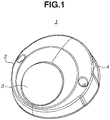
- Fig. 1 is an external view of the network camera 1.
- the network camera 1 includes a fixing cover 2, a dome cover 3, a base 4, a pan/tilt/rotation unit (not illustrated), and an imaging unit 10.
- the fixing cover 2 is attached and fixed to the base 4.
- the dome cover 3 has a hemispherical shape.
- the dome cover 3 is a transparent resin member, and fixed to the fixing cover 2.
- the dome cover 3, the fixing cover 2, and the base 4 form a housing. In the housing, the pan/tilt/rotation unit and the imaging unit 10 are arranged.
- the pan/tilt/rotation unit is a member that rotatably supports the imaging unit 10 in pan/tilt/rotation directions.
- the imaging unit 10 includes a lens 111 and an image sensor 5 as illustrated in Figs. 2 and 3 . Details of the imaging unit 10 will be described below.
- Fig. 2 is an external view of the imaging unit 10 to be mounted on the network camera 1.
- Fig. 3 is an exploded perspective view of the imaging unit 10.
- the imaging unit 10 includes a front cover 6, a rear cover 7, the image sensor 5, and a lens barrel 100 as illustrated in Fig. 3 .
- the front cover 6 includes an opening 6a and covers the lens barrel 100.
- the lens 111 is inserted from the opening 6a.
- the front cover 6 is located on the side nearer the dome cover 3.
- the rear cover 7 covers the lens barrel 100 and the image sensor 5.
- the front cover 6 and the rear cover 7 are fixed together with screws 8 and 9.
- the lens barrel 100 and the image sensor 5 integrated together are internally sandwiched between the front cover 6 and the rear cover 7.
- the image sensor 5 converts an optical subject image formed by an optical system into an electric signal.
- the lens barrel 100 includes a filter holder 103, and the filter holder 103 holds an infrared cut filter (IRCF) 106. Details of the lens barrel 100 will be described below.
- IRCF infrared cut filter
- Fig. 4 is a perspective view of the lens barrel 100.
- Fig. 5 is an exploded perspective view of the lens barrel 100.
- the lens barrel 100 includes an image sensor protection rubber 101, a filter base 102 (holding base), the filter holder 103 (holding frame), a lens holder 104 (fixing component), and an actuator 105 as illustrated in Fig. 5 .
- the image sensor protection rubber 101 is a member for protecting the image sensor 5 and is situated between the filter base 102 and an image sensor substrate 5a.
- the filter base 102 is a member for holding the filter holder 103.
- the filter base 102 holding the filter holder 103 is inserted into an opening 1041 (refer to Fig. 8C ) of the lens holder 104, and thereby being attached to the lens holder 104.
- the filter holder 103 is a member for holding the IRCF 106 (optical element) and a glass 107 (optical element).
- the filter holder 103 is placed on and removed from an optical path by the actuator 105.
- the actuator 105 For example, in a case where a sufficient amount of light is provided to the image sensor 5, the IRCF 106 is placed on an optical axis 11, whereas in a case where a sufficient amount of light is not provided to the image sensor 5, the IRCF 106 is removed from the optical axis 11.
- the glass 107 prevents a focal point position from changing when the IRCF 106 is removed from the optical axis 11, especially in a case where the lens barrel 100 is a lens having a fixed focal point.
- the lens holder 104 holds the lens 111 (imaging lens).
- the image sensor protection rubber 101, the image sensor substrate 5a with the image sensor 5 mounted thereon, and the actuator 105 are attached to the lens holder 104.
- the lens holder 104 includes the opening 1041 (refer to Fig. 8C ) and an actuator attachment portion 1048. Through the opening 1041 (refer to Fig. 8C ), the filter base 102 holding the filter holder 103 is to be inserted.
- the actuator 105 is to be attached to the actuator attachment portion 1048.
- the lens 111 is fixed to the lens holder 104.
- the lens holder 104 may have a mount portion to which a removable interchangeable lens is to be attached.
- the actuator 105 is a member for placing the filter holder 103 on the optical axis 11 or removing the filter holder 103 from the optical axis 11.
- the actuator 105 includes a motor 108 and a gear train 109 (driving gear).
- the gear train 109 is covered by a gear cover 113 and engaged with a gear engagement portion 1031 of the filter holder 103. This engagement transmits driving force of the motor 108 to the filter holder 103.
- a control unit (not illustrated) changes a voltage to the motor 108 and a rotation direction of the motor 108, thereby moving the filter holder 103 in a direction orthogonal to the optical axis 11 and removing the filter holder 103 from the optical path.
- the actuator 105 includes a photo-interrupter 110.
- a light shielding portion 112 attached to the filter holder 103 shields the photo-interrupter 110 from light.
- the IRCF 106 is on the optical axis 11, light enters the photo-interrupter 110. With this structure, it is detected whether the IRCF 106 is on the optical axis 11.
- a flexible print substrate 114 electrically connects the motor 108 and the photo-interrupter 110 to the image sensor substrate 5a, to which the image sensor 5 is connected, and a main substrate (not illustrated).
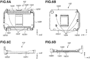
- Fig. 6A illustrates an external view of the filter base 102 viewed from the lens 111.
- Fig. 6B illustrates an external view of the filter base 102 viewed from the image sensor 5.
- Fig. 6C is an external view of the filter base 102 illustrated in Fig. 6A viewed from the bottom.
- Fig. 6D illustrates an external view of the filter base 102 in Fig. 6B viewed from the top.
- the filter base 102 includes a guide 1026, sliding surfaces 1022, a bottom plate 1023, side walls 1027 and 1028, an abutment surface 10251 (second abutment), an abutment surface 10252, and an abutment surface 1029 as illustrated in Fig. 6A .
- the filter base 102 also includes abutment surfaces 1024 (fourth abutment) as illustrated in Fig. 6B .
- the guide 1026 and the sliding surfaces 1022 are members for guiding the filter holder 103 to place and remove the filter holder 103 on and from the optical axis 11.
- the guide 1026 engages with guides 1036 (described below) of the filter holder 103, and the sliding surfaces 1022 slides against sliding surfaces 1032 (described below) of the filter holder 103.
- the abutment surfaces 1024 are members for clearing a space between the filter base 102 and the lens holder 104 by moving the filter base 102 toward the lens holder 104 when the assembly of the filter base 102 to the lens holder 104 is completed. Specifically, when the assembly of the filter base 102 to the lens holder 104 is completed, the abutment surfaces 1024 abuts abutment surfaces 1044 of the lens holder 104, so that a length of a gap between the filter base 102 and the lens holder 104 becomes substantially zero in a front-rear direction.
- the abutment surfaces 1024 are also formed on the opposite side to the surface on which the guide 1026 and the sliding surfaces 1022 are formed. In other words, the abutment surfaces 1024 are formed on the side of the image sensor substrate 5a.
- the bottom plate 1023 includes a depressed portion 10231 near the gear train 109.
- the side walls 1027 and 1028 are provided at respective ends of the filter base 102.
- An end of the side wall 1028 has a substantially acute-angled shape portion 10281 (engagement portion).
- the substantially acute-angled shape portion 10281 engages with the gear train 109 and rotates the gear train 109 when the filter base 102 is assembled to the lens holder 104.
- the substantially acute-angled shape portion 10281 in the present exemplary embodiment has a gear shape that is substantially the same as the gear engagement portion 1031.
- the substantially acute-angled shape portion 10281 can have any shape as long as the shape does not obstruct the rotation of the gear train 109.
- the substantially acute-angled shape portion 10281 comes near an inner wall of the lens holder 104 when the filter base 102 is assembled to the lens holder 104.
- the substantially acute-angled shape portion 10281 thereby has a function of reducing entering dust in parallel.
- the abutment surfaces 10251 and 10252 protrude from a lower surface of the filter base 102.
- the abutment surfaces 10251 and 10252 abut an abutment surface 1045 of the lens holder 104 when the filter base 102 is assembled to the lens holder 104.
- the substantially acute-angled shape portion 10281 of the filter base 102 is brought near the inner wall of the lens holder 104 to thereby reduce entering dust.
- the abutment surface 1045 will be described below.
- the abutment surface 1029 protrudes from an upper surface of the filter base 102.
- the abutment surface 1029 abuts an abutment surface 1049 of the lens holder 104 when the filter base 102 is assembled to the lens holder 104.
- Fig. 7A is a perspective view of the filter holder 103 viewed from the lens 111.
- Fig. 7B is a perspective view of the filter holder 103 viewed from the image sensor 5.
- the filter holder 103 includes a plurality of sliding surfaces 1033, the gear engagement portion 1031 (gear), and a directing portion 10311 (guide) as illustrated in Fig. 7A .
- the filter holder 103 further includes a plurality of sliding surfaces 1032 and guides 1036 as illustrated in Fig. 7B .
- the sliding surfaces 1032 slide against the sliding surfaces 1022 of the filter base 102, and the guides 1036 are engaged with the guide 1026 of the filter base 102.
- the sliding of the filter holder 103 is thereby regulated in the direction (top-bottom direction) orthogonal to the optical axis 11.
- the gear engagement portion 1031 engages with the gear train 109.
- the gear engagement portion 1031 transmits driving force of the motor 108 to the filter holder 103.
- the directing portion 10311 is provided next to the gear engagement portion 1031.
- the directing portion 10311 engages with the gear train 109 when the filter base 102 is assembled to the lens holder 104.
- the directing portion 10311 does not engage with the gear train 109 when the IRCF 106 is placed or removed.
- the directing portion 10311 has a shape similar to the gear engagement portion 1031.
- the directing portion 10311 can have any shape as long as the shape prevents teeth tips of the gear train 109 from interfering with the filter holder 103 when the filter base 102 is assembled to the lens holder 104.
- the directing portion 10311 can also have a concavo/convex shape different from the shape of the gear engagement portion 1031, such as a sloped surface or planar surface.
- the directing portion 10311 is formed at one end of the gear engagement portion 1031 in the right-left direction.
- the directing portion 10311 can be formed at both ends of the gear engagement portion 1031 in the right-left direction.
- the directing portion 10311 is placed at a place where the directing portion 10311 does not engage with the gear train 109 until the abutment surface 10251 of the filter base 102 abuts the abutment surface 1045 of the lens holder 104. Specifically, a leading edge of the directing portion 10311 is farther from the gear train 109 than a leading edge of the substantially acute-angled shape portion 10281 is until the abutment surface 10251 of the filter base 102 abuts the abutment surface 1045 of the lens holder 104.
- Fig. 8A is an external view of the lens holder 104 viewed from the lens 111.
- Fig. 8B is an external view of the lens holder 104 viewed from the image sensor 5.
- Fig. 8C is a cross-sectional view of the lens holder 104 taken along a plane including the optical axis 11 and specified by a dashed-dotted line illustrated in Fig. 8A.
- Fig. 8D is a perspective view of the lens holder 104 viewed from the image sensor 5.
- the lens holder 104 includes the openings 1041 and 1042, sliding surfaces 1043, the abutment surfaces 1044 (third abutment), the abutment surface 1045 (first abutment), and the abutment surface 1049.
- the openings 1041 and 1042 are pierced through the lens holder 104 in the direction (right-left direction) orthogonal to the optical axis 11 of the lens 111 as illustrated in Fig. 8C .
- a plurality of sliding surfaces 1043 is provided on an optical axis orthogonal surface (first orthogonal surface) on a lens 111 side (imaging lens side).
- the sliding surfaces 1043 slides against the sliding surfaces 1022 of the filter base 102 when the filter base 102 is assembled to the lens holder 104.
- a plurality of abutment surfaces 1044 is provided on a second orthogonal surface, which is an optical axis orthogonal surface facing the first orthogonal surface.
- the abutment surfaces 1044 abut the abutment surfaces 1024 of the filter base 102.
- the plurality of abutment surfaces 1044 abuts the plurality of abutment surfaces 1024 of the filter base 102 so that a length of a gap between the filter base 102 and the lens holder 104 in the front-back direction becomes substantially zero.
- the abutment surface 1045 is a surface parallel to a plane that includes a piercing direction (right-left direction) of the opening 1041 and the direction of the optical axis 11 of the lens 111 as illustrated in Figs. 8B and 8D .
- the abutment surface 1045 abuts the abutment surface 10251 of the filter base 102 when the filter base 102 is assembled to the lens holder 104.
- the substantially acute-angled shape portion 10281 of the filter base 102 is brought near the inner wall of the lens holder 104, and thereby reducing entering dust.
- the abutment surface 1049 abuts the abutment surface 1029 of the filter base 102 when the filter base 102 is assembled to the lens holder 104.
- Figs. 9A to 9D illustrate a state where assembly of the filter base 102 to the lens holder 104 is started.
- Fig. 9A is an external view as viewed from the lens 111.
- Fig. 9B is a cross-sectional view taken along a plane (cross section A) including the optical axis 11 and specified by a dashed-dotted line illustrated in Fig. 9A as viewed from the bottom.
- Fig. 9C is a detail view of a region around the side wall 1028 specified by a dotted line illustrated in Fig. 9B.
- Fig. 9D is a cross-sectional view taken along a cross section B specified in Fig. 9B .
- Figs. 9A to Fig. 12G the relationship between the gear train 109 and the filter base 102 is focused, so that the motor 108 and the gear cover 113 are not illustrated. However, the motor 108 and the gear cover 113 can be attached.
- the image sensor protection rubber 101 is attached to the lens holder 104 before the filter base 102 and the filter holder 103 are assembled to the lens holder 104.
- the filter base 102 and the filter holder 103 can be assembled to the lens holder 104 before the image sensor protection rubber 101 is attached to the lens holder 104.
- the filter holder 103 is assembled to the filter base 102. Specifically, the filter holder 103 is assembled to the filter base 102 such that the sliding surfaces 1022 of the filter base 102 faces the sliding surfaces 1032 of the filter holder 103 and the guide 1026 of the filter base 102 faces to the guides 1036 of the filter holder 103 as described above.
- the filter base 102 is assembled into the lens holder 104 in the right-left direction from the opening 1041 formed on the lens holder 104, as illustrated in Fig. 9B . At this time, the substantially acute-angled shape portion 10281 of the filter base 102 and the gear train 109 are not in contact with each other.
- the abutment surfaces 1024 of the filter base 102 does not abut the abutment surfaces 1044 of the lens holder 104 in the front-back direction as illustrated in Fig. 9C .
- a length of S is greater than a length of S' as illustrated in Fig. 9C , the relationship between these spaces is not limited thereto.
- the abutment surface 10251 of the filter base 102 does not abut the abutment surface 1045 of the lens holder 104 in the top-bottom direction.
- the substantially acute-angled shape portion 10281 of the filter base 102 and the inner wall of the lens holder 104 are not yet near each other.
- Figs. 10A to 10D illustrate a state where the gear train 109 and the filter base 102 are brought into contact with each other.
- Fig. 10A is an external view viewed from the lens 111.
- Fig. 10B is a cross-sectional view taken along a plane (cross section A) including the optical axis 11 and specified by a dashed-dotted line illustrated in Fig. 10A as viewed from the bottom.
- Fig. 10C is a cross-sectional view taken along a cross section B specified by a dashed-dotted line illustrated in Fig. 10B.
- Fig. 10D is a detail view of a region around the gear train 109 that is specified by a dotted line in Fig. 10C .
- the gear train 109 and the substantially acute-angled shape portion 10281 of the filter base 102 come into contact and are engaged with each other as illustrated in Figs. 10A to 10D . If the filter base 102 is further assembled in the right-left direction, the gear train 109 rotates, and the filter base 102 is assembled to the lens holder 104. The bottom plate 1023 of the filter base 102 is placed lower than the gear train 109, so that the bottom plate 1023 is prevented from coming into contact with the gear train 109.
- the abutment surfaces 1024 of the filter base 102 does not abut the abutment surfaces 1044 of the lens holder 104.
- the abutment surface 10251 of the filter base 102 does not abut the abutment surface 1045 of the lens holder 104 in the top-bottom direction.
- the substantially acute-angled shape portion 10281 of the filter base 102 and the inner wall of the lens holder 104 are not yet near each other.
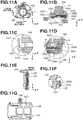
- Figs. 11A to 11G illustrate a state immediately before the lens holder 104 has been assembled to the filter base 102.
- Fig. 11A is an external view viewed from the lens 111.
- Fig. 11B is a cross-sectional view taken along a plane (cross section A) including the optical axis 11 and specified by a dashed-dotted line illustrated in Fig. 11A as viewed from the bottom.
- Fig. 11C is a detail view (detail view 1) of a region around the opening 1041 specified by a dotted line illustrated in Fig. 11B.
- Fig. 11D is a detail view (detail view 2) of a region around the opening 1042 specified by another dotted line illustrated in Fig. 11B.
- Fig. 11A is an external view viewed from the lens 111.
- Fig. 11B is a cross-sectional view taken along a plane (cross section A) including the optical axis 11 and specified by a dashed-dotted line illustrated in Fig
- FIG. 11E is a schematic cross-sectional view taken along a cross section B specified by another dashed-dotted line illustrated in Fig. 11A.
- Fig. 11F is a detail view (detail view 3) of a region around the gear train 109 specified by a dotted line illustrated in Fig. 11E.
- Fig. 11G illustrates a state of engagement around the gear train 109.
- relationships are focused among the gear train 109, the filter base 102, and the filter holder 103, so that the other members are omitted.
- the filter base 102 is further assembled in the right-left direction from the state illustrated in Figs. 10A to 10D , the abutment surface 10251 of the filter base 102 abuts the abutment surface 1045 of the lens holder 104. Consequently, the filter base 102 moves upward, and the directing portion 10311 of the filter holder 103 engages with the gear train 109. Thereafter, the filter base 102 moves in the right-left direction while the gear engagement portion 1031 of the filter holder 103 engages with the gear train 109, as illustrated in Fig. 10G .
- the bottom plate 1023 of the filter base 102 is brought near the gear train 109. However, the depressed portion 10231 is provided, and thereby the bottom plate 1023 is prevented from coming into contact with the gear train 109.
- the abutment surfaces 1024 of the filter base 102 do not abut the abutment surfaces 1044 of the lens holder 104. Thus, at this time, there are spaces S and S' provided as illustrated in Fig. 9C . There is also a space between the openings 1041 and 1042 of the lens holder 104 and the side walls 1027 and 1028 of the filter base 102 in the front-back direction.
- the abutment surface 10251 of the filter base 102 abuts the abutment surface 1045 of the lens holder 104.
- the substantially acute-angled shape portion 10281 of the filter base 102 is thereby near the inner wall of the lens holder 104.
- Figs. 12A to 12G illustrate a state where the lens holder 104 has been assembled to the filter base 102.
- Fig. 12A is an external view viewed from the lens 111.
- Fig. 12B is a cross-sectional view taken along a plane (cross section A) including the optical axis 11 and specified by a dashed-dotted line illustrated in Fig. 12A as viewed from the bottom.
- Fig. 12C is a detail view (detail view 1) of a region around the opening 1041 specified by a dotted line illustrated in Fig. 12B.
- Fig. 12D is a detail view (detail view 2) of a region around the opening 1042 specified by another dotted line illustrated in Fig. 12B.
- Fig. 12A is an external view viewed from the lens 111.
- Fig. 12B is a cross-sectional view taken along a plane (cross section A) including the optical axis 11 and specified by a dashed-dotted line illustrated in Fig.
- FIG. 12E is a schematic cross-sectional view taken along a cross section B specified by another dashed-dotted line illustrated in Fig. 12A.
- Fig. 12F is a detail view (detail view 3) of a region around the gear train 109 specified by a dotted line illustrated in Fig. 12E.
- Fig. 12G is a side view of the lens holder 104.
- relationships are focused among the gear train 109, the filter base 102, and the filter holder 103, so that the other members are omitted.
- the filter base 102 is further assembled in the right-left direction from the state illustrated in Figs. 11A to 11G , the filter base 102 is in a state where the assembly has been completed as illustrated in Figs. 12A to 12G .
- a length of S is greater than a length of T and a length of S' is greater than a length of T', and the sliding surfaces 1033 of the filter holder 103 slidably abut the sliding surfaces 1043 of the lens holder 104, and the filter base 102 abuts the lens holder 104 such that the filter base 102 is tightly fixed to the lens holder 104.
- a space between the openings 1041 and 1042 of the lens holder 104 and the side walls 1027 and 1028 of the filter base 102 is substantially zero in the front-back direction.
- the substantially acute-angled shape portion 10281 of the filter base 102 is near the inner wall of the lens holder 104 as illustrated in Fig. 12G , and thus a distance between the filter base 102 and the lens holder 104 is substantially zero when viewed from the side.
- the filter base 102 when the filter base 102 is assembled to the lens holder 104, the gear train 109 engages with the substantially acute-angled shape portion 10281 of the filter base 102, and the gear train 109 rotates.
- the filter base 102 can thereby be assembled to the lens holder 104 even in a state where the gear train 109 is placed on the lens holder 104.
- the filter base 102 can be assembled to and removed from the lens holder 104 regardless of the presence/absence of the gear train 109, so that ease of assembly and removal increases.
- the bottom plate 1023 of the filter base 102 comes near the gear train 109.
- the bottom plate 1023 is prevented from coming into contact with the gear train 109 by providing the depressed portion 10231.
- a length of a gap between the side walls 1027 and 1028 of external surfaces of the filter base 102 and the openings 1041 and 1042 of the lens holder 104 becomes substantially zero, and thereby external dust can be prevented from entering and incident light can also be reduced.
- the side wall 1028 and the opening 1042 come near each other by providing the substantially acute-angled shape portion 10281, and thereby reducing entering dust.
- the filter base 102 and the lens holder 104 have the sliding surfaces 1022 and 1043 in the present exemplary embodiment, the filter base 102 can have a cover member and sliding surfaces in the optical axis direction and then the filter base 102 can be inserted.
- the actuator 105 is not illustrated in Figs. 9A to 12G , the gear train 109 can directly be connected to the motor 108 and driven by the motor 108, or a plurality of gear trains 109 can be connected together and driven indirectly by the motor 108.
- removal is also executable by executing the removal in reverse order of the assembly.
- Embodiment(s) of the present invention can also be realized by a computer of a system or apparatus that reads out and executes computer executable instructions (e.g., one or more programs) recorded on a storage medium (which may also be referred to more fully as a 'non-transitory computer-readable storage medium') to perform the functions of one or more of the above-described embodiment(s) and/or that includes one or more circuits (e.g., application specific integrated circuit (ASIC)) for performing the functions of one or more of the above-described embodiment(s), and by a method performed by the computer of the system or apparatus by, for example, reading out and executing the computer executable instructions from the storage medium to perform the functions of one or more of the above-described embodiment(s) and/or controlling the one or more circuits to perform the functions of one or more of the above-described embodiment(s).
- computer executable instructions e.g., one or more programs
- a storage medium which may also be referred to more fully as
- the computer may comprise one or more processors (e.g., central processing unit (CPU), micro processing unit (MPU)) and may include a network of separate computers or separate processors to read out and execute the computer executable instructions.
- the computer executable instructions may be provided to the computer, for example, from a network or the storage medium.
- the storage medium may include, for example, one or more of a hard disk, a random-access memory (RAM), a read only memory (ROM), a storage of distributed computing systems, an optical disk (such as a compact disc (CD), digital versatile disc (DVD), or Blu-ray Disc (BD)TM), a flash memory device, a memory card, and the like.
Landscapes
- Physics & Mathematics (AREA)
- General Physics & Mathematics (AREA)
- Optics & Photonics (AREA)
- Engineering & Computer Science (AREA)
- Multimedia (AREA)
- Signal Processing (AREA)
- Blocking Light For Cameras (AREA)
- Structure And Mechanism Of Cameras (AREA)
- Accessories Of Cameras (AREA)
- Studio Devices (AREA)
- Camera Bodies And Camera Details Or Accessories (AREA)
- Electrophotography Configuration And Component (AREA)
Abstract
Description
- The present invention relates to imaging apparatuses, in particular, imaging apparatuses including a mechanism that inserts and removes an optical element, such as an optical filter, into and from an optical path.
- Imaging apparatuses, such as monitoring cameras, that include an optical filter selection mechanism have been known. The optical filter selection mechanism removes or inserts an infrared cut optical filter from or into an optical path to acquire an image using infrared rays during image capturing at night or in the dark and without using the optical filter when it is not required.
- A method of assembling an optical filter to a lens barrel from an opening formed on a side surface of the lens barrel is also known. For example, Japanese Patent Laid-Open No.
H4-163429 - According to Japanese Patent Laid-Open No.
H4-163429 - The present invention in its one aspect provides an imaging apparatus as specified in
claims 1 to 11. - Further features of the present invention will become apparent from the following description of exemplary embodiments with reference to the attached drawings.
-
-
Fig. 1 is an external view of a network camera. -
Fig. 2 is an external view of an imaging unit mounted on the network camera. -
Fig. 3 is an exploded perspective view of the imaging unit. -
Fig. 4 is a perspective view of a lens barrel. -
Fig. 5 illustrates an exploded perspective view of the lens barrel. -
Fig. 6A illustrates an external view of a filter base viewed from the front. -
Fig. 6B illustrates an external view of the filter base viewed from the back. -
Fig. 6C illustrates an external view of the filter base viewed from the bottom. -
Fig. 6D illustrates an external view of the filter base viewed from the top. -
Fig. 7A illustrates a perspective view of a filter holder viewed from the front. -
Fig. 7B illustrates a perspective view of the filter holder viewed from the back. -
Fig. 8A illustrates an external view of a lens holder viewed from the front. -
Fig. 8B illustrates an external view of the lens holder viewed from the back. -
Fig. 8C illustrates a cross-sectional view of the lens holder taken along a plane including anoptical axis 11 and specified by a dashed-dotted line illustrated inFig. 8A . -
Fig. 8D illustrates a perspective view of the lens holder viewed from the back. -
Fig. 9A is a diagram illustrating a state where the filter base is being assembled to the lens holder. -
Fig. 9B is a diagram illustrating a state where the filter base is being assembled to the lens holder. -
Fig. 9C is a diagram illustrating a state where the filter base is being assembled to the lens holder. -
Fig. 9D is a diagram illustrating a state where the filter base is being assembled to the lens holder. -
Fig. 10A is a diagram illustrating a state where the filter base is being assembled to the lens holder. -
Fig. 10B is a diagram illustrating a state where the filter base is being assembled to the lens holder. -
Fig. 10C is a diagram illustrating a state where the filter base is being assembled to the lens holder. -
Fig. 10D is a diagram illustrating a state where the filter base is being assembled to the lens holder. -
Fig. 11A is a diagram illustrating a state immediately before assembly of the filter base to the lens holder is completed. -
Fig. 11B is a diagram illustrating a state immediately before assembly of the filter base to the lens holder is completed. -
Fig. 11C is a diagram illustrating a state immediately before assembly of the filter base to the lens holder is completed. -
Fig. 11D is a diagram illustrating a state immediately before assembly of the filter base to the lens holder is completed. -
Fig. 11E is a diagram illustrating a state immediately before assembly of the filter base to the lens holder is completed. -
Fig. 11F is a diagram illustrating a state immediately before assembly of the filter base to the lens holder is completed. -
Fig. 11G is a diagram illustrating a state immediately before assembly of the filter base to the lens holder is completed. -
Fig. 12A is a diagram illustrating a state where assembly of the filter base to the lens holder is completed. -
Fig. 12B is a diagram illustrating a state where assembly of the filter base to the lens holder is completed. -
Fig. 12C is a diagram illustrating a state where assembly of the filter base to the lens holder is completed. -
Fig. 12D is a diagram illustrating a state where assembly of the filter base to the lens holder is completed. -
Fig. 12E is a diagram illustrating a state where assembly of the filter base to the lens holder is completed. -
Fig. 12F is a diagram illustrating a state where assembly of the filter base to the lens holder is completed. -
Fig. 12G is a diagram illustrating a state where assembly of the filter base to the lens holder is completed. - According to an exemplary embodiment of the present invention, an imaging apparatus that enables easy removal of an optical element selection unit from a lens barrel and easy assembly of the optical element selection unit to the lens barrel is provided.
- Hereinafter, embodiments will be described in detail with reference to the attached drawings. Note, the following embodiments are not intended to limit the scope of the claimed invention. Multiple features are described in the embodiments, but limitation is not made an invention that requires all such features, and multiple such features may be combined as appropriate. Furthermore, in the attached drawings, the same reference numerals are given to the same or similar configurations, and redundant description thereof is omitted.
- An entire structure of a
network camera 1 will now be described with reference toFig. 1 as an example of an imaging apparatus.Fig. 1 is an external view of thenetwork camera 1. - The
network camera 1 includes a fixingcover 2, adome cover 3, abase 4, a pan/tilt/rotation unit (not illustrated), and animaging unit 10. - The fixing
cover 2 is attached and fixed to thebase 4. - The
dome cover 3 has a hemispherical shape. Thedome cover 3 is a transparent resin member, and fixed to the fixingcover 2. Thedome cover 3, the fixingcover 2, and thebase 4 form a housing. In the housing, the pan/tilt/rotation unit and theimaging unit 10 are arranged. - The pan/tilt/rotation unit is a member that rotatably supports the
imaging unit 10 in pan/tilt/rotation directions. - The
imaging unit 10 includes alens 111 and animage sensor 5 as illustrated inFigs. 2 and3 . Details of theimaging unit 10 will be described below. - Details of the
imaging unit 10 will now be described with reference toFigs. 2 and3 .Fig. 2 is an external view of theimaging unit 10 to be mounted on thenetwork camera 1.Fig. 3 is an exploded perspective view of theimaging unit 10. Theimaging unit 10 includes afront cover 6, arear cover 7, theimage sensor 5, and alens barrel 100 as illustrated inFig. 3 . - The
front cover 6 includes anopening 6a and covers thelens barrel 100. Thelens 111 is inserted from theopening 6a. Thefront cover 6 is located on the side nearer thedome cover 3. - The
rear cover 7 covers thelens barrel 100 and theimage sensor 5. Thefront cover 6 and therear cover 7 are fixed together withscrews 8 and 9. Thelens barrel 100 and theimage sensor 5 integrated together are internally sandwiched between thefront cover 6 and therear cover 7. - The
image sensor 5 converts an optical subject image formed by an optical system into an electric signal. - The
lens barrel 100 includes afilter holder 103, and thefilter holder 103 holds an infrared cut filter (IRCF) 106. Details of thelens barrel 100 will be described below. - Details of the
lens barrel 100 will now be described with reference toFigs. 4 and5 .Fig. 4 is a perspective view of thelens barrel 100.Fig. 5 is an exploded perspective view of thelens barrel 100. Thelens barrel 100 includes an imagesensor protection rubber 101, a filter base 102 (holding base), the filter holder 103 (holding frame), a lens holder 104 (fixing component), and anactuator 105 as illustrated inFig. 5 . - The image
sensor protection rubber 101 is a member for protecting theimage sensor 5 and is situated between thefilter base 102 and animage sensor substrate 5a. - The
filter base 102 is a member for holding thefilter holder 103. Thefilter base 102 holding thefilter holder 103 is inserted into an opening 1041 (refer toFig. 8C ) of thelens holder 104, and thereby being attached to thelens holder 104. - The
filter holder 103 is a member for holding the IRCF 106 (optical element) and a glass 107 (optical element). Thefilter holder 103 is placed on and removed from an optical path by theactuator 105. For example, in a case where a sufficient amount of light is provided to theimage sensor 5, theIRCF 106 is placed on anoptical axis 11, whereas in a case where a sufficient amount of light is not provided to theimage sensor 5, theIRCF 106 is removed from theoptical axis 11. Theglass 107 prevents a focal point position from changing when theIRCF 106 is removed from theoptical axis 11, especially in a case where thelens barrel 100 is a lens having a fixed focal point. - The
lens holder 104 holds the lens 111 (imaging lens). The imagesensor protection rubber 101, theimage sensor substrate 5a with theimage sensor 5 mounted thereon, and theactuator 105 are attached to thelens holder 104. Thelens holder 104 includes the opening 1041 (refer toFig. 8C ) and anactuator attachment portion 1048. Through the opening 1041 (refer toFig. 8C ), thefilter base 102 holding thefilter holder 103 is to be inserted. Theactuator 105 is to be attached to theactuator attachment portion 1048. In the present exemplary embodiment, thelens 111 is fixed to thelens holder 104. However, thelens holder 104 may have a mount portion to which a removable interchangeable lens is to be attached. - The
actuator 105 is a member for placing thefilter holder 103 on theoptical axis 11 or removing thefilter holder 103 from theoptical axis 11. Theactuator 105 includes amotor 108 and a gear train 109 (driving gear). Thegear train 109 is covered by agear cover 113 and engaged with agear engagement portion 1031 of thefilter holder 103. This engagement transmits driving force of themotor 108 to thefilter holder 103. A control unit (not illustrated) changes a voltage to themotor 108 and a rotation direction of themotor 108, thereby moving thefilter holder 103 in a direction orthogonal to theoptical axis 11 and removing thefilter holder 103 from the optical path. - The
actuator 105 includes a photo-interrupter 110. When theIRCF 106 is removed from theoptical axis 11, alight shielding portion 112 attached to thefilter holder 103 shields the photo-interrupter 110 from light. When theIRCF 106 is on theoptical axis 11, light enters the photo-interrupter 110. With this structure, it is detected whether theIRCF 106 is on theoptical axis 11. Aflexible print substrate 114 electrically connects themotor 108 and the photo-interrupter 110 to theimage sensor substrate 5a, to which theimage sensor 5 is connected, and a main substrate (not illustrated). - Next, details of the
filter base 102 will be described with reference toFigs. 6A to 6D. Fig. 6A illustrates an external view of thefilter base 102 viewed from thelens 111.Fig. 6B illustrates an external view of thefilter base 102 viewed from theimage sensor 5.Fig. 6C is an external view of thefilter base 102 illustrated inFig. 6A viewed from the bottom.Fig. 6D illustrates an external view of thefilter base 102 inFig. 6B viewed from the top. - The
filter base 102 includes aguide 1026, slidingsurfaces 1022, abottom plate 1023,side walls abutment surface 10252, and anabutment surface 1029 as illustrated inFig. 6A . Thefilter base 102 also includes abutment surfaces 1024 (fourth abutment) as illustrated inFig. 6B . - The
guide 1026 and the slidingsurfaces 1022 are members for guiding thefilter holder 103 to place and remove thefilter holder 103 on and from theoptical axis 11. When thefilter holder 103 moves in a direction (right-left direction) orthogonal to theoptical axis 11, theguide 1026 engages with guides 1036 (described below) of thefilter holder 103, and the slidingsurfaces 1022 slides against sliding surfaces 1032 (described below) of thefilter holder 103. - The abutment surfaces 1024 are members for clearing a space between the
filter base 102 and thelens holder 104 by moving thefilter base 102 toward thelens holder 104 when the assembly of thefilter base 102 to thelens holder 104 is completed. Specifically, when the assembly of thefilter base 102 to thelens holder 104 is completed, the abutment surfaces 1024 abutsabutment surfaces 1044 of thelens holder 104, so that a length of a gap between thefilter base 102 and thelens holder 104 becomes substantially zero in a front-rear direction. The abutment surfaces 1024 are also formed on the opposite side to the surface on which theguide 1026 and the slidingsurfaces 1022 are formed. In other words, the abutment surfaces 1024 are formed on the side of theimage sensor substrate 5a. - The
bottom plate 1023 includes adepressed portion 10231 near thegear train 109. - The
side walls filter base 102. An end of theside wall 1028 has a substantially acute-angled shape portion 10281 (engagement portion). The substantially acute-angledshape portion 10281 engages with thegear train 109 and rotates thegear train 109 when thefilter base 102 is assembled to thelens holder 104. The substantially acute-angledshape portion 10281 in the present exemplary embodiment has a gear shape that is substantially the same as thegear engagement portion 1031. However, the substantially acute-angledshape portion 10281 can have any shape as long as the shape does not obstruct the rotation of thegear train 109. The substantially acute-angledshape portion 10281 comes near an inner wall of thelens holder 104 when thefilter base 102 is assembled to thelens holder 104. The substantially acute-angledshape portion 10281 thereby has a function of reducing entering dust in parallel. - The abutment surfaces 10251 and 10252 protrude from a lower surface of the
filter base 102. The abutment surfaces 10251 and 10252 abut anabutment surface 1045 of thelens holder 104 when thefilter base 102 is assembled to thelens holder 104. With this structure, the substantially acute-angledshape portion 10281 of thefilter base 102 is brought near the inner wall of thelens holder 104 to thereby reduce entering dust. Theabutment surface 1045 will be described below. - The
abutment surface 1029 protrudes from an upper surface of thefilter base 102. Theabutment surface 1029 abuts anabutment surface 1049 of thelens holder 104 when thefilter base 102 is assembled to thelens holder 104. - Next, details of the
filter holder 103 will be described with reference toFigs. 7A and 7B. Fig. 7A is a perspective view of thefilter holder 103 viewed from thelens 111.Fig. 7B is a perspective view of thefilter holder 103 viewed from theimage sensor 5. - The
filter holder 103 includes a plurality of slidingsurfaces 1033, the gear engagement portion 1031 (gear), and a directing portion 10311 (guide) as illustrated inFig. 7A . Thefilter holder 103 further includes a plurality of slidingsurfaces 1032 and guides 1036 as illustrated inFig. 7B . - When the
filter holder 103 moves in the direction orthogonal to theoptical axis 11, the slidingsurfaces 1032 slide against the slidingsurfaces 1022 of thefilter base 102, and theguides 1036 are engaged with theguide 1026 of thefilter base 102. The sliding of thefilter holder 103 is thereby regulated in the direction (top-bottom direction) orthogonal to theoptical axis 11. - The
gear engagement portion 1031 engages with thegear train 109. Thegear engagement portion 1031 transmits driving force of themotor 108 to thefilter holder 103. - The directing
portion 10311 is provided next to thegear engagement portion 1031. The directingportion 10311 engages with thegear train 109 when thefilter base 102 is assembled to thelens holder 104. The directingportion 10311 does not engage with thegear train 109 when theIRCF 106 is placed or removed. In the present exemplary embodiment, the directingportion 10311 has a shape similar to thegear engagement portion 1031. The directingportion 10311 can have any shape as long as the shape prevents teeth tips of thegear train 109 from interfering with thefilter holder 103 when thefilter base 102 is assembled to thelens holder 104. However, the directingportion 10311 can also have a concavo/convex shape different from the shape of thegear engagement portion 1031, such as a sloped surface or planar surface. In the present exemplary embodiment, the directingportion 10311 is formed at one end of thegear engagement portion 1031 in the right-left direction. However, the directingportion 10311 can be formed at both ends of thegear engagement portion 1031 in the right-left direction. - The directing
portion 10311 is placed at a place where the directingportion 10311 does not engage with thegear train 109 until theabutment surface 10251 of thefilter base 102 abuts theabutment surface 1045 of thelens holder 104. Specifically, a leading edge of the directingportion 10311 is farther from thegear train 109 than a leading edge of the substantially acute-angledshape portion 10281 is until theabutment surface 10251 of thefilter base 102 abuts theabutment surface 1045 of thelens holder 104. - Details of the
lens holder 104 will now be described with reference toFigs. 8A to 8D. Fig. 8A is an external view of thelens holder 104 viewed from thelens 111.Fig. 8B is an external view of thelens holder 104 viewed from theimage sensor 5.Fig. 8C is a cross-sectional view of thelens holder 104 taken along a plane including theoptical axis 11 and specified by a dashed-dotted line illustrated inFig. 8A. Fig. 8D is a perspective view of thelens holder 104 viewed from theimage sensor 5. - The
lens holder 104 includes theopenings surfaces 1043, the abutment surfaces 1044 (third abutment), the abutment surface 1045 (first abutment), and theabutment surface 1049. - The
openings lens holder 104 in the direction (right-left direction) orthogonal to theoptical axis 11 of thelens 111 as illustrated inFig. 8C . - In the space formed by the
openings lens holder 104, a plurality of slidingsurfaces 1043 is provided on an optical axis orthogonal surface (first orthogonal surface) on alens 111 side (imaging lens side). The slidingsurfaces 1043 slides against the slidingsurfaces 1022 of thefilter base 102 when thefilter base 102 is assembled to thelens holder 104. - A plurality of
abutment surfaces 1044 is provided on a second orthogonal surface, which is an optical axis orthogonal surface facing the first orthogonal surface. The abutment surfaces 1044 abut the abutment surfaces 1024 of thefilter base 102. - When the assembly of the
filter base 102 to thelens holder 104 is completed, the plurality ofabutment surfaces 1044 abuts the plurality ofabutment surfaces 1024 of thefilter base 102 so that a length of a gap between thefilter base 102 and thelens holder 104 in the front-back direction becomes substantially zero. - The
abutment surface 1045 is a surface parallel to a plane that includes a piercing direction (right-left direction) of theopening 1041 and the direction of theoptical axis 11 of thelens 111 as illustrated inFigs. 8B and 8D . Theabutment surface 1045 abuts theabutment surface 10251 of thefilter base 102 when thefilter base 102 is assembled to thelens holder 104. Thus, the substantially acute-angledshape portion 10281 of thefilter base 102 is brought near the inner wall of thelens holder 104, and thereby reducing entering dust. - The
abutment surface 1049 abuts theabutment surface 1029 of thefilter base 102 when thefilter base 102 is assembled to thelens holder 104. - A procedure of assembling the
filter base 102 and thefilter holder 103 to thelens holder 104 will now be described with reference toFigs. 9A to 12G . -
Figs. 9A to 9D illustrate a state where assembly of thefilter base 102 to thelens holder 104 is started.Fig. 9A is an external view as viewed from thelens 111.Fig. 9B is a cross-sectional view taken along a plane (cross section A) including theoptical axis 11 and specified by a dashed-dotted line illustrated inFig. 9A as viewed from the bottom.Fig. 9C is a detail view of a region around theside wall 1028 specified by a dotted line illustrated inFig. 9B. Fig. 9D is a cross-sectional view taken along a cross section B specified inFig. 9B . - In
Figs. 9A to Fig. 12G , the relationship between thegear train 109 and thefilter base 102 is focused, so that themotor 108 and thegear cover 113 are not illustrated. However, themotor 108 and thegear cover 113 can be attached. The imagesensor protection rubber 101 is attached to thelens holder 104 before thefilter base 102 and thefilter holder 103 are assembled to thelens holder 104. Alternatively, thefilter base 102 and thefilter holder 103 can be assembled to thelens holder 104 before the imagesensor protection rubber 101 is attached to thelens holder 104. - The
filter holder 103 is assembled to thefilter base 102. Specifically, thefilter holder 103 is assembled to thefilter base 102 such that the slidingsurfaces 1022 of thefilter base 102 faces the slidingsurfaces 1032 of thefilter holder 103 and theguide 1026 of thefilter base 102 faces to theguides 1036 of thefilter holder 103 as described above. - The
filter base 102 is assembled into thelens holder 104 in the right-left direction from theopening 1041 formed on thelens holder 104, as illustrated inFig. 9B . At this time, the substantially acute-angledshape portion 10281 of thefilter base 102 and thegear train 109 are not in contact with each other. - The abutment surfaces 1024 of the
filter base 102 does not abut the abutment surfaces 1044 of thelens holder 104 in the front-back direction as illustrated inFig. 9C . Thus, there is a space S between the slidingsurfaces 1033 of thefilter holder 103 and the slidingsurfaces 1043 of thelens holder 104, and there is a space S' between thefilter base 102 and thelens holder 104 as illustrated inFig. 9C . There is also a space between the opening 1041 of thelens holder 104 and theside wall 1028 of thefilter base 102. Although a length of S is greater than a length of S' as illustrated inFig. 9C , the relationship between these spaces is not limited thereto. - The
abutment surface 10251 of thefilter base 102 does not abut theabutment surface 1045 of thelens holder 104 in the top-bottom direction. Thus, the substantially acute-angledshape portion 10281 of thefilter base 102 and the inner wall of thelens holder 104 are not yet near each other. - Each state illustrated in
Figs. 10A to 10D will now be described. -
Figs. 10A to 10D illustrate a state where thegear train 109 and thefilter base 102 are brought into contact with each other.Fig. 10A is an external view viewed from thelens 111.Fig. 10B is a cross-sectional view taken along a plane (cross section A) including theoptical axis 11 and specified by a dashed-dotted line illustrated inFig. 10A as viewed from the bottom.Fig. 10C is a cross-sectional view taken along a cross section B specified by a dashed-dotted line illustrated inFig. 10B. Fig. 10D is a detail view of a region around thegear train 109 that is specified by a dotted line inFig. 10C . - If the
filter base 102 is assembled in the right-left direction from the state illustrated inFigs. 9A to 9D , thegear train 109 and the substantially acute-angledshape portion 10281 of thefilter base 102 come into contact and are engaged with each other as illustrated inFigs. 10A to 10D . If thefilter base 102 is further assembled in the right-left direction, thegear train 109 rotates, and thefilter base 102 is assembled to thelens holder 104. Thebottom plate 1023 of thefilter base 102 is placed lower than thegear train 109, so that thebottom plate 1023 is prevented from coming into contact with thegear train 109. - At this time, the abutment surfaces 1024 of the
filter base 102 does not abut the abutment surfaces 1044 of thelens holder 104. Thus, at this time, there are spaces S and S' provided as illustrated inFig. 9C . There is also a space between the opening 1041 of thelens holder 104 and theside wall 1028 of thefilter base 102 in the front-back direction. - The
abutment surface 10251 of thefilter base 102 does not abut theabutment surface 1045 of thelens holder 104 in the top-bottom direction. Thus, the substantially acute-angledshape portion 10281 of thefilter base 102 and the inner wall of thelens holder 104 are not yet near each other. - A state illustrated in
Figs. 11A to 11G will now be described. -
Figs. 11A to 11G illustrate a state immediately before thelens holder 104 has been assembled to thefilter base 102.Fig. 11A is an external view viewed from thelens 111.Fig. 11B is a cross-sectional view taken along a plane (cross section A) including theoptical axis 11 and specified by a dashed-dotted line illustrated inFig. 11A as viewed from the bottom.Fig. 11C is a detail view (detail view 1) of a region around theopening 1041 specified by a dotted line illustrated inFig. 11B. Fig. 11D is a detail view (detail view 2) of a region around theopening 1042 specified by another dotted line illustrated inFig. 11B. Fig. 11E is a schematic cross-sectional view taken along a cross section B specified by another dashed-dotted line illustrated inFig. 11A. Fig. 11F is a detail view (detail view 3) of a region around thegear train 109 specified by a dotted line illustrated inFig. 11E. Fig. 11G illustrates a state of engagement around thegear train 109. InFig. 11E , relationships are focused among thegear train 109, thefilter base 102, and thefilter holder 103, so that the other members are omitted. - If the
filter base 102 is further assembled in the right-left direction from the state illustrated inFigs. 10A to 10D , theabutment surface 10251 of thefilter base 102 abuts theabutment surface 1045 of thelens holder 104. Consequently, thefilter base 102 moves upward, and the directingportion 10311 of thefilter holder 103 engages with thegear train 109. Thereafter, thefilter base 102 moves in the right-left direction while thegear engagement portion 1031 of thefilter holder 103 engages with thegear train 109, as illustrated inFig. 10G . Thebottom plate 1023 of thefilter base 102 is brought near thegear train 109. However, thedepressed portion 10231 is provided, and thereby thebottom plate 1023 is prevented from coming into contact with thegear train 109. - The abutment surfaces 1024 of the
filter base 102 do not abut the abutment surfaces 1044 of thelens holder 104. Thus, at this time, there are spaces S and S' provided as illustrated inFig. 9C . There is also a space between theopenings lens holder 104 and theside walls filter base 102 in the front-back direction. - As described above, the
abutment surface 10251 of thefilter base 102 abuts theabutment surface 1045 of thelens holder 104. The substantially acute-angledshape portion 10281 of thefilter base 102 is thereby near the inner wall of thelens holder 104. - A state illustrated in
Figs. 12A to 12G will now be described. -
Figs. 12A to 12G illustrate a state where thelens holder 104 has been assembled to thefilter base 102.Fig. 12A is an external view viewed from thelens 111.Fig. 12B is a cross-sectional view taken along a plane (cross section A) including theoptical axis 11 and specified by a dashed-dotted line illustrated inFig. 12A as viewed from the bottom.Fig. 12C is a detail view (detail view 1) of a region around theopening 1041 specified by a dotted line illustrated inFig. 12B. Fig. 12D is a detail view (detail view 2) of a region around theopening 1042 specified by another dotted line illustrated inFig. 12B. Fig. 12E is a schematic cross-sectional view taken along a cross section B specified by another dashed-dotted line illustrated inFig. 12A. Fig. 12F is a detail view (detail view 3) of a region around thegear train 109 specified by a dotted line illustrated inFig. 12E. Fig. 12G is a side view of thelens holder 104. InFig. 12E , relationships are focused among thegear train 109, thefilter base 102, and thefilter holder 103, so that the other members are omitted. - If the
filter base 102 is further assembled in the right-left direction from the state illustrated inFigs. 11A to 11G , thefilter base 102 is in a state where the assembly has been completed as illustrated inFigs. 12A to 12G . - At this time, the abutment surfaces 1024 of the
filter base 102 abut the abutment surfaces 1044 of thelens holder 104. Consequently, the spaces S and S' in assembling are narrowed to spaces T and T', so that the space is reduced. Specifically, a length of S is greater than a length of T and a length of S' is greater than a length of T', and the slidingsurfaces 1033 of thefilter holder 103 slidably abut the slidingsurfaces 1043 of thelens holder 104, and thefilter base 102 abuts thelens holder 104 such that thefilter base 102 is tightly fixed to thelens holder 104. Further, a space between theopenings lens holder 104 and theside walls filter base 102 is substantially zero in the front-back direction. - The substantially acute-angled
shape portion 10281 of thefilter base 102 is near the inner wall of thelens holder 104 as illustrated inFig. 12G , and thus a distance between thefilter base 102 and thelens holder 104 is substantially zero when viewed from the side. - As described above, when the
filter base 102 is assembled to thelens holder 104, thegear train 109 engages with the substantially acute-angledshape portion 10281 of thefilter base 102, and thegear train 109 rotates. Thefilter base 102 can thereby be assembled to thelens holder 104 even in a state where thegear train 109 is placed on thelens holder 104. Thus, thefilter base 102 can be assembled to and removed from thelens holder 104 regardless of the presence/absence of thegear train 109, so that ease of assembly and removal increases. - When the
filter base 102 is assembled to thelens holder 104, thebottom plate 1023 of thefilter base 102 comes near thegear train 109. However, thebottom plate 1023 is prevented from coming into contact with thegear train 109 by providing thedepressed portion 10231. - When assembly of the
filter base 102 to thelens holder 104 is completed, a length of a gap between theside walls filter base 102 and theopenings lens holder 104 becomes substantially zero, and thereby external dust can be prevented from entering and incident light can also be reduced. - Even while the
opening 1042 is pierced, theside wall 1028 and theopening 1042 come near each other by providing the substantially acute-angledshape portion 10281, and thereby reducing entering dust. - While the
filter base 102 and thelens holder 104 have the slidingsurfaces filter base 102 can have a cover member and sliding surfaces in the optical axis direction and then thefilter base 102 can be inserted. Although theactuator 105 is not illustrated inFigs. 9A to 12G , thegear train 109 can directly be connected to themotor 108 and driven by themotor 108, or a plurality ofgear trains 109 can be connected together and driven indirectly by themotor 108. - While assembly is described in the present exemplary embodiment, it should be noted that removal is also executable by executing the removal in reverse order of the assembly.
- While various exemplary embodiments of the present invention are described above, the descriptions herein are not intended to limit the present invention. Various modified examples including deletion, addition, and replacement of components are possible within the technical scope of the invention.
- Embodiment(s) of the present invention can also be realized by a computer of a system or apparatus that reads out and executes computer executable instructions (e.g., one or more programs) recorded on a storage medium (which may also be referred to more fully as a 'non-transitory computer-readable storage medium') to perform the functions of one or more of the above-described embodiment(s) and/or that includes one or more circuits (e.g., application specific integrated circuit (ASIC)) for performing the functions of one or more of the above-described embodiment(s), and by a method performed by the computer of the system or apparatus by, for example, reading out and executing the computer executable instructions from the storage medium to perform the functions of one or more of the above-described embodiment(s) and/or controlling the one or more circuits to perform the functions of one or more of the above-described embodiment(s). The computer may comprise one or more processors (e.g., central processing unit (CPU), micro processing unit (MPU)) and may include a network of separate computers or separate processors to read out and execute the computer executable instructions. The computer executable instructions may be provided to the computer, for example, from a network or the storage medium. The storage medium may include, for example, one or more of a hard disk, a random-access memory (RAM), a read only memory (ROM), a storage of distributed computing systems, an optical disk (such as a compact disc (CD), digital versatile disc (DVD), or Blu-ray Disc (BD)™), a flash memory device, a memory card, and the like.
- While the present invention has been described with reference to exemplary embodiments, it is to be understood that the invention is not limited to the disclosed exemplary embodiments.
Claims (11)
- An imaging apparatus (1) comprising:a fixing component (104) arranged to fix an imaging lens and has a side surface including an opening;a holding frame (103) arranged to hold an optical element;a holding base (102) arranged to be inserted into the opening from a direction orthogonal to an optical axis of the imaging lens and to hold the holding frame (103); anda driving gear (109) arranged to drive the holding frame (103) in the direction orthogonal to the optical axis of the imaging lens,wherein the holding base (102) has an engagement portion (10281) arranged to engage with the driving gear (109) in a case that the holding base(102) is inserted into the opening.
- The imaging apparatus according to claim 1,
wherein the opening is pierced through the fixing component (104) in the direction orthogonal to the optical axis, and
wherein the holding base (102) includes a side wall arranged to fill a space between the opening and the fixing component when an insertion of the holding base is completed in the opening. - The imaging apparatus according to claim 2,
wherein the holding base (102) has a first abutment that is a surface parallel to a plane that includes a piercing direction of the opening and a direction of the optical axis of the imaging lens,
wherein the fixing component (104) has a second abutment that abuts the first abutment, and
wherein the side wall is brought near the fixing component when the first abutment and the second abutment abut each other. - The imaging apparatus according to claim 2 or 3, wherein the side wall includes the engagement portion (10281).
- The imaging apparatus according to any one of preceding claims, wherein the holding frame (103) includes:a gear (1031) arranged to engage with the driving gear (109); anda guide that is next to the gear (108) and abuts the driving gear in a case that the holding base (102) is inserted into the fixing component (104).
- The imaging apparatus according to claim 5, wherein the guide is arranged not to abut the driving gear (109) when the holding frame (103) is removed from or inserted into an optical path.
- The imaging apparatus according to any one of preceding claims,
wherein a surface on a side of the imaging lens in an internal space in the fixing component (104) formed by the opening is a first orthogonal surface orthogonal to the optical axis,
wherein a surface that faces the first orthogonal surface is a second orthogonal surface orthogonal to the optical axis,
wherein the fixing component includes a third abutment on the second orthogonal surface, and
wherein the holding base (102) includes a fourth abutment arranged to abut the third abutment in the direction of the optical axis. - The imaging apparatus according to claim 7, wherein the holding base (102) has a bottom plate that is arranged not to be in contact with the driving gear (109) when the third abutment and the fourth abutment do not abut each other.
- The imaging apparatus according to claim 8, wherein the bottom plate has a depressed portion that is arranged not to be in contact with the driving gear (109) when the third abutment and the fourth abutment abut each other.
- The imaging apparatus according to any one of claims 7-9,
wherein a plurality of the third abutments and a plurality of the fourth abutments are provided. - The imaging apparatus according to any one of preceding claims, wherein the driving gear (109) is arranged to be directly or indirectly connected to a motor and driven by the motor.
Applications Claiming Priority (1)
| Application Number | Priority Date | Filing Date | Title |
|---|---|---|---|
| JP2019204310A JP7418082B2 (en) | 2019-11-11 | 2019-11-11 | Imaging device |
Publications (2)
| Publication Number | Publication Date |
|---|---|
| EP3820137A1 true EP3820137A1 (en) | 2021-05-12 |
| EP3820137B1 EP3820137B1 (en) | 2023-01-18 |
Family
ID=73020072
Family Applications (1)
| Application Number | Title | Priority Date | Filing Date |
|---|---|---|---|
| EP20203846.9A Active EP3820137B1 (en) | 2019-11-11 | 2020-10-26 | Imaging apparatus |
Country Status (4)
| Country | Link |
|---|---|
| US (1) | US11378869B2 (en) |
| EP (1) | EP3820137B1 (en) |
| JP (1) | JP7418082B2 (en) |
| CN (1) | CN112782911B (en) |
Families Citing this family (3)
| Publication number | Priority date | Publication date | Assignee | Title |
|---|---|---|---|---|
| KR102850778B1 (en) * | 2020-08-31 | 2025-08-26 | 엘지전자 주식회사 | Filter assembly and drying apparatus having the same |
| JP2023106138A (en) * | 2022-01-20 | 2023-08-01 | パナソニックIpマネジメント株式会社 | Imaging device |
| JP2024152343A (en) * | 2023-04-14 | 2024-10-25 | キヤノン株式会社 | Lens barrel unit |
Citations (4)
| Publication number | Priority date | Publication date | Assignee | Title |
|---|---|---|---|---|
| JPH04163429A (en) | 1990-10-26 | 1992-06-09 | Canon Inc | How to assemble a lens barrel with a lens system and PN filter |
| US20120257097A1 (en) * | 2011-04-08 | 2012-10-11 | Sony Corporation | Imaging apparatus |
| EP3477936A1 (en) * | 2017-10-25 | 2019-05-01 | Canon Kabushiki Kaisha | Imaging apparatus |
| EP3722857A1 (en) * | 2019-04-10 | 2020-10-14 | Canon Kabushiki Kaisha | Image-capturing apparatus |
Family Cites Families (13)
| Publication number | Priority date | Publication date | Assignee | Title |
|---|---|---|---|---|
| US2399658A (en) * | 1944-03-08 | 1946-05-07 | Banker Russell Ellsworth | Single knob variable density filter control |
| JP4257641B2 (en) * | 2003-03-24 | 2009-04-22 | フジノン株式会社 | Lens device |
| JP2005128116A (en) * | 2003-10-22 | 2005-05-19 | Seiko Precision Inc | Optical module |
| CN101393315B (en) * | 2006-02-10 | 2011-05-18 | 松下电器产业株式会社 | Lens barrel and image pickup device |
| JP4821847B2 (en) * | 2008-12-26 | 2011-11-24 | ソニー株式会社 | Optical component switching mechanism, lens barrel, and imaging device |
| WO2013107166A1 (en) * | 2012-01-19 | 2013-07-25 | 上海锐势机器视觉科技有限公司 | Camera with built-in polaroid switching mechanism |
| JP6452085B2 (en) * | 2013-08-06 | 2019-01-16 | パナソニックIpマネジメント株式会社 | Camera device and filter unit |
| CN105635528B (en) * | 2014-10-29 | 2020-04-07 | 鸿富锦精密工业(深圳)有限公司 | Camera module |
| JP2018010054A (en) * | 2016-07-11 | 2018-01-18 | キヤノン電子株式会社 | Shutter drive device and imaging device |
| JP6562311B2 (en) * | 2016-10-26 | 2019-08-21 | パナソニックIpマネジメント株式会社 | Lens barrel and imaging device |
| JP7146515B2 (en) | 2017-10-25 | 2022-10-04 | キヤノン株式会社 | Imaging device |
| JP6746855B2 (en) * | 2018-09-28 | 2020-08-26 | エスゼット ディージェイアイ テクノロジー カンパニー リミテッドSz Dji Technology Co.,Ltd | Imaging device, control method, and program |
| JP2020056839A (en) * | 2018-09-28 | 2020-04-09 | パナソニック株式会社 | Imaging apparatus |
-
2019
- 2019-11-11 JP JP2019204310A patent/JP7418082B2/en active Active
-
2020
- 2020-10-26 EP EP20203846.9A patent/EP3820137B1/en active Active
- 2020-11-06 US US17/091,808 patent/US11378869B2/en active Active
- 2020-11-09 CN CN202011237877.4A patent/CN112782911B/en active Active
Patent Citations (5)
| Publication number | Priority date | Publication date | Assignee | Title |
|---|---|---|---|---|
| JPH04163429A (en) | 1990-10-26 | 1992-06-09 | Canon Inc | How to assemble a lens barrel with a lens system and PN filter |
| US20120257097A1 (en) * | 2011-04-08 | 2012-10-11 | Sony Corporation | Imaging apparatus |
| EP3477936A1 (en) * | 2017-10-25 | 2019-05-01 | Canon Kabushiki Kaisha | Imaging apparatus |
| EP3722857A1 (en) * | 2019-04-10 | 2020-10-14 | Canon Kabushiki Kaisha | Image-capturing apparatus |
| EP3722856A1 (en) * | 2019-04-10 | 2020-10-14 | Canon Kabushiki Kaisha | Image-capturing apparatus |
Also Published As
| Publication number | Publication date |
|---|---|
| JP2021078032A (en) | 2021-05-20 |
| CN112782911A (en) | 2021-05-11 |
| EP3820137B1 (en) | 2023-01-18 |
| JP7418082B2 (en) | 2024-01-19 |
| US11378869B2 (en) | 2022-07-05 |
| CN112782911B (en) | 2022-11-11 |
| US20210141292A1 (en) | 2021-05-13 |
Similar Documents
| Publication | Publication Date | Title |
|---|---|---|
| US8294816B2 (en) | Imaging apparatus containing lens mount without mirror box | |
| US11378869B2 (en) | Optical element holding apparatus with orthogonally inserted holding base | |
| US11196905B2 (en) | Image-capturing apparatus for reducing a number of components of an optical element switching mechanism | |
| US20120076480A1 (en) | Imaging unit | |
| CN102768454A (en) | Imaging apparatus | |
| JP5485428B2 (en) | Digital camera | |
| US9063392B2 (en) | Imaging unit | |
| JP6156928B2 (en) | Camera case and its waterproof structure | |
| JP6004726B2 (en) | Imaging device | |
| CN111812916B (en) | Image pickup apparatus | |
| JP2009128626A (en) | Digital camera | |
| JP4923575B2 (en) | camera | |
| US20250068039A1 (en) | Imaging apparatus | |
| JP4893948B2 (en) | Imaging unit and imaging apparatus | |
| JP5430071B2 (en) | Optical element holding mechanism and imaging apparatus | |
| JP2019004248A (en) | Imaging device | |
| JP2010177965A (en) | Digital camera | |
| JP2020187237A (en) | Imaging device | |
| JP2019138972A (en) | Imaging device | |
| JP5513541B2 (en) | Digital camera | |
| JP2023160037A (en) | Optical filter switching device and imaging device | |
| JP2007052358A (en) | Optical unit | |
| JP2007180939A (en) | Electric apparatus for selectively arranging translucent body | |
| JP2006323029A (en) | Camera | |
| US20170242217A1 (en) | Lens barrel provided in image pickup apparatus, and image pickup apparatus |
Legal Events
| Date | Code | Title | Description |
|---|---|---|---|
| PUAI | Public reference made under article 153(3) epc to a published international application that has entered the european phase |
Free format text: ORIGINAL CODE: 0009012 |
|
| STAA | Information on the status of an ep patent application or granted ep patent |
Free format text: STATUS: THE APPLICATION HAS BEEN PUBLISHED |
|
| AK | Designated contracting states |
Kind code of ref document: A1 Designated state(s): AL AT BE BG CH CY CZ DE DK EE ES FI FR GB GR HR HU IE IS IT LI LT LU LV MC MK MT NL NO PL PT RO RS SE SI SK SM TR |
|
| STAA | Information on the status of an ep patent application or granted ep patent |
Free format text: STATUS: REQUEST FOR EXAMINATION WAS MADE |
|
| 17P | Request for examination filed |
Effective date: 20211112 |
|
| RBV | Designated contracting states (corrected) |
Designated state(s): AL AT BE BG CH CY CZ DE DK EE ES FI FR GB GR HR HU IE IS IT LI LT LU LV MC MK MT NL NO PL PT RO RS SE SI SK SM TR |
|
| GRAP | Despatch of communication of intention to grant a patent |
Free format text: ORIGINAL CODE: EPIDOSNIGR1 |
|
| STAA | Information on the status of an ep patent application or granted ep patent |
Free format text: STATUS: GRANT OF PATENT IS INTENDED |
|
| INTG | Intention to grant announced |
Effective date: 20220929 |
|
| GRAS | Grant fee paid |
Free format text: ORIGINAL CODE: EPIDOSNIGR3 |
|
| GRAA | (expected) grant |
Free format text: ORIGINAL CODE: 0009210 |
|
| STAA | Information on the status of an ep patent application or granted ep patent |
Free format text: STATUS: THE PATENT HAS BEEN GRANTED |
|
| AK | Designated contracting states |
Kind code of ref document: B1 Designated state(s): AL AT BE BG CH CY CZ DE DK EE ES FI FR GB GR HR HU IE IS IT LI LT LU LV MC MK MT NL NO PL PT RO RS SE SI SK SM TR |
|
| REG | Reference to a national code |
Ref country code: GB Ref legal event code: FG4D |
|
| REG | Reference to a national code |
Ref country code: DE Ref legal event code: R096 Ref document number: 602020007660 Country of ref document: DE |
|
| REG | Reference to a national code |
Ref country code: CH Ref legal event code: EP |
|
| REG | Reference to a national code |
Ref country code: AT Ref legal event code: REF Ref document number: 1545284 Country of ref document: AT Kind code of ref document: T Effective date: 20230215 Ref country code: IE Ref legal event code: FG4D |
|
| REG | Reference to a national code |
Ref country code: LT Ref legal event code: MG9D |
|
| REG | Reference to a national code |
Ref country code: NL Ref legal event code: MP Effective date: 20230118 |
|
| REG | Reference to a national code |
Ref country code: AT Ref legal event code: MK05 Ref document number: 1545284 Country of ref document: AT Kind code of ref document: T Effective date: 20230118 |
|
| PG25 | Lapsed in a contracting state [announced via postgrant information from national office to epo] |
Ref country code: NL Free format text: LAPSE BECAUSE OF FAILURE TO SUBMIT A TRANSLATION OF THE DESCRIPTION OR TO PAY THE FEE WITHIN THE PRESCRIBED TIME-LIMIT Effective date: 20230118 |
|
| PG25 | Lapsed in a contracting state [announced via postgrant information from national office to epo] |
Ref country code: RS Free format text: LAPSE BECAUSE OF FAILURE TO SUBMIT A TRANSLATION OF THE DESCRIPTION OR TO PAY THE FEE WITHIN THE PRESCRIBED TIME-LIMIT Effective date: 20230118 Ref country code: PT Free format text: LAPSE BECAUSE OF FAILURE TO SUBMIT A TRANSLATION OF THE DESCRIPTION OR TO PAY THE FEE WITHIN THE PRESCRIBED TIME-LIMIT Effective date: 20230518 Ref country code: NO Free format text: LAPSE BECAUSE OF FAILURE TO SUBMIT A TRANSLATION OF THE DESCRIPTION OR TO PAY THE FEE WITHIN THE PRESCRIBED TIME-LIMIT Effective date: 20230418 Ref country code: LV Free format text: LAPSE BECAUSE OF FAILURE TO SUBMIT A TRANSLATION OF THE DESCRIPTION OR TO PAY THE FEE WITHIN THE PRESCRIBED TIME-LIMIT Effective date: 20230118 Ref country code: LT Free format text: LAPSE BECAUSE OF FAILURE TO SUBMIT A TRANSLATION OF THE DESCRIPTION OR TO PAY THE FEE WITHIN THE PRESCRIBED TIME-LIMIT Effective date: 20230118 Ref country code: HR Free format text: LAPSE BECAUSE OF FAILURE TO SUBMIT A TRANSLATION OF THE DESCRIPTION OR TO PAY THE FEE WITHIN THE PRESCRIBED TIME-LIMIT Effective date: 20230118 Ref country code: ES Free format text: LAPSE BECAUSE OF FAILURE TO SUBMIT A TRANSLATION OF THE DESCRIPTION OR TO PAY THE FEE WITHIN THE PRESCRIBED TIME-LIMIT Effective date: 20230118 Ref country code: AT Free format text: LAPSE BECAUSE OF FAILURE TO SUBMIT A TRANSLATION OF THE DESCRIPTION OR TO PAY THE FEE WITHIN THE PRESCRIBED TIME-LIMIT Effective date: 20230118 |
|
| PG25 | Lapsed in a contracting state [announced via postgrant information from national office to epo] |
Ref country code: SE Free format text: LAPSE BECAUSE OF FAILURE TO SUBMIT A TRANSLATION OF THE DESCRIPTION OR TO PAY THE FEE WITHIN THE PRESCRIBED TIME-LIMIT Effective date: 20230118 Ref country code: PL Free format text: LAPSE BECAUSE OF FAILURE TO SUBMIT A TRANSLATION OF THE DESCRIPTION OR TO PAY THE FEE WITHIN THE PRESCRIBED TIME-LIMIT Effective date: 20230118 Ref country code: IS Free format text: LAPSE BECAUSE OF FAILURE TO SUBMIT A TRANSLATION OF THE DESCRIPTION OR TO PAY THE FEE WITHIN THE PRESCRIBED TIME-LIMIT Effective date: 20230518 Ref country code: GR Free format text: LAPSE BECAUSE OF FAILURE TO SUBMIT A TRANSLATION OF THE DESCRIPTION OR TO PAY THE FEE WITHIN THE PRESCRIBED TIME-LIMIT Effective date: 20230419 Ref country code: FI Free format text: LAPSE BECAUSE OF FAILURE TO SUBMIT A TRANSLATION OF THE DESCRIPTION OR TO PAY THE FEE WITHIN THE PRESCRIBED TIME-LIMIT Effective date: 20230118 |
|
| REG | Reference to a national code |
Ref country code: DE Ref legal event code: R097 Ref document number: 602020007660 Country of ref document: DE |
|
| PG25 | Lapsed in a contracting state [announced via postgrant information from national office to epo] |
Ref country code: SM Free format text: LAPSE BECAUSE OF FAILURE TO SUBMIT A TRANSLATION OF THE DESCRIPTION OR TO PAY THE FEE WITHIN THE PRESCRIBED TIME-LIMIT Effective date: 20230118 Ref country code: RO Free format text: LAPSE BECAUSE OF FAILURE TO SUBMIT A TRANSLATION OF THE DESCRIPTION OR TO PAY THE FEE WITHIN THE PRESCRIBED TIME-LIMIT Effective date: 20230118 Ref country code: EE Free format text: LAPSE BECAUSE OF FAILURE TO SUBMIT A TRANSLATION OF THE DESCRIPTION OR TO PAY THE FEE WITHIN THE PRESCRIBED TIME-LIMIT Effective date: 20230118 Ref country code: DK Free format text: LAPSE BECAUSE OF FAILURE TO SUBMIT A TRANSLATION OF THE DESCRIPTION OR TO PAY THE FEE WITHIN THE PRESCRIBED TIME-LIMIT Effective date: 20230118 Ref country code: CZ Free format text: LAPSE BECAUSE OF FAILURE TO SUBMIT A TRANSLATION OF THE DESCRIPTION OR TO PAY THE FEE WITHIN THE PRESCRIBED TIME-LIMIT Effective date: 20230118 |
|
| PLBE | No opposition filed within time limit |
Free format text: ORIGINAL CODE: 0009261 |
|
| STAA | Information on the status of an ep patent application or granted ep patent |
Free format text: STATUS: NO OPPOSITION FILED WITHIN TIME LIMIT |
|
| PG25 | Lapsed in a contracting state [announced via postgrant information from national office to epo] |
Ref country code: SK Free format text: LAPSE BECAUSE OF FAILURE TO SUBMIT A TRANSLATION OF THE DESCRIPTION OR TO PAY THE FEE WITHIN THE PRESCRIBED TIME-LIMIT Effective date: 20230118 |
|
| 26N | No opposition filed |
Effective date: 20231019 |
|
| PG25 | Lapsed in a contracting state [announced via postgrant information from national office to epo] |
Ref country code: SI Free format text: LAPSE BECAUSE OF FAILURE TO SUBMIT A TRANSLATION OF THE DESCRIPTION OR TO PAY THE FEE WITHIN THE PRESCRIBED TIME-LIMIT Effective date: 20230118 |
|
| PG25 | Lapsed in a contracting state [announced via postgrant information from national office to epo] |
Ref country code: IT Free format text: LAPSE BECAUSE OF FAILURE TO SUBMIT A TRANSLATION OF THE DESCRIPTION OR TO PAY THE FEE WITHIN THE PRESCRIBED TIME-LIMIT Effective date: 20230118 Ref country code: MC Free format text: LAPSE BECAUSE OF FAILURE TO SUBMIT A TRANSLATION OF THE DESCRIPTION OR TO PAY THE FEE WITHIN THE PRESCRIBED TIME-LIMIT Effective date: 20230118 |
|
| REG | Reference to a national code |
Ref country code: CH Ref legal event code: PL |
|
| REG | Reference to a national code |
Ref country code: BE Ref legal event code: MM Effective date: 20231031 |
|
| PG25 | Lapsed in a contracting state [announced via postgrant information from national office to epo] |
Ref country code: LU Free format text: LAPSE BECAUSE OF NON-PAYMENT OF DUE FEES Effective date: 20231026 |
|
| PG25 | Lapsed in a contracting state [announced via postgrant information from national office to epo] |
Ref country code: LU Free format text: LAPSE BECAUSE OF NON-PAYMENT OF DUE FEES Effective date: 20231026 |
|
| PG25 | Lapsed in a contracting state [announced via postgrant information from national office to epo] |
Ref country code: CH Free format text: LAPSE BECAUSE OF NON-PAYMENT OF DUE FEES Effective date: 20231031 |
|
| PG25 | Lapsed in a contracting state [announced via postgrant information from national office to epo] |
Ref country code: CH Free format text: LAPSE BECAUSE OF NON-PAYMENT OF DUE FEES Effective date: 20231031 |
|
| PG25 | Lapsed in a contracting state [announced via postgrant information from national office to epo] |
Ref country code: BE Free format text: LAPSE BECAUSE OF NON-PAYMENT OF DUE FEES Effective date: 20231031 |
|
| PG25 | Lapsed in a contracting state [announced via postgrant information from national office to epo] |
Ref country code: IE Free format text: LAPSE BECAUSE OF NON-PAYMENT OF DUE FEES Effective date: 20231026 |
|
| PG25 | Lapsed in a contracting state [announced via postgrant information from national office to epo] |
Ref country code: IE Free format text: LAPSE BECAUSE OF NON-PAYMENT OF DUE FEES Effective date: 20231026 |
|
| PG25 | Lapsed in a contracting state [announced via postgrant information from national office to epo] |
Ref country code: BG Free format text: LAPSE BECAUSE OF FAILURE TO SUBMIT A TRANSLATION OF THE DESCRIPTION OR TO PAY THE FEE WITHIN THE PRESCRIBED TIME-LIMIT Effective date: 20230118 |
|
| PG25 | Lapsed in a contracting state [announced via postgrant information from national office to epo] |
Ref country code: BG Free format text: LAPSE BECAUSE OF FAILURE TO SUBMIT A TRANSLATION OF THE DESCRIPTION OR TO PAY THE FEE WITHIN THE PRESCRIBED TIME-LIMIT Effective date: 20230118 |
|
| PG25 | Lapsed in a contracting state [announced via postgrant information from national office to epo] |
Ref country code: CY Free format text: LAPSE BECAUSE OF FAILURE TO SUBMIT A TRANSLATION OF THE DESCRIPTION OR TO PAY THE FEE WITHIN THE PRESCRIBED TIME-LIMIT; INVALID AB INITIO Effective date: 20201026 |
|
| PG25 | Lapsed in a contracting state [announced via postgrant information from national office to epo] |
Ref country code: HU Free format text: LAPSE BECAUSE OF FAILURE TO SUBMIT A TRANSLATION OF THE DESCRIPTION OR TO PAY THE FEE WITHIN THE PRESCRIBED TIME-LIMIT; INVALID AB INITIO Effective date: 20201026 |
|
| PGFP | Annual fee paid to national office [announced via postgrant information from national office to epo] |
Ref country code: GB Payment date: 20250923 Year of fee payment: 6 |
|
| PGFP | Annual fee paid to national office [announced via postgrant information from national office to epo] |
Ref country code: FR Payment date: 20250924 Year of fee payment: 6 |
|
| PG25 | Lapsed in a contracting state [announced via postgrant information from national office to epo] |
Ref country code: TR Free format text: LAPSE BECAUSE OF FAILURE TO SUBMIT A TRANSLATION OF THE DESCRIPTION OR TO PAY THE FEE WITHIN THE PRESCRIBED TIME-LIMIT Effective date: 20230118 |
|
| PGFP | Annual fee paid to national office [announced via postgrant information from national office to epo] |
Ref country code: DE Payment date: 20250923 Year of fee payment: 6 |