EP3819917A1 - Nuclear reactor decommissioning system - Google Patents
Nuclear reactor decommissioning system Download PDFInfo
- Publication number
- EP3819917A1 EP3819917A1 EP19831384.3A EP19831384A EP3819917A1 EP 3819917 A1 EP3819917 A1 EP 3819917A1 EP 19831384 A EP19831384 A EP 19831384A EP 3819917 A1 EP3819917 A1 EP 3819917A1
- Authority
- EP
- European Patent Office
- Prior art keywords
- reactor
- shielding
- nuclear reactor
- decommissioning system
- cylindrical members
- Prior art date
- Legal status (The legal status is an assumption and is not a legal conclusion. Google has not performed a legal analysis and makes no representation as to the accuracy of the status listed.)
- Granted
Links
Images


Classifications
-
- G—PHYSICS
- G21—NUCLEAR PHYSICS; NUCLEAR ENGINEERING
- G21D—NUCLEAR POWER PLANT
- G21D1/00—Details of nuclear power plant
- G21D1/003—Nuclear facilities decommissioning arrangements
-
- G—PHYSICS
- G21—NUCLEAR PHYSICS; NUCLEAR ENGINEERING
- G21C—NUCLEAR REACTORS
- G21C1/00—Reactor types
- G21C1/04—Thermal reactors ; Epithermal reactors
- G21C1/06—Heterogeneous reactors, i.e. in which fuel and moderator are separated
- G21C1/08—Heterogeneous reactors, i.e. in which fuel and moderator are separated moderator being highly pressurised, e.g. boiling water reactor, integral super-heat reactor, pressurised water reactor
- G21C1/086—Pressurised water reactors
-
- G—PHYSICS
- G21—NUCLEAR PHYSICS; NUCLEAR ENGINEERING
- G21F—PROTECTION AGAINST X-RADIATION, GAMMA RADIATION, CORPUSCULAR RADIATION OR PARTICLE BOMBARDMENT; TREATING RADIOACTIVELY CONTAMINATED MATERIAL; DECONTAMINATION ARRANGEMENTS THEREFOR
- G21F7/00—Shielded cells or rooms
- G21F7/06—Structural combination with remotely-controlled apparatus, e.g. with manipulators
-
- G—PHYSICS
- G21—NUCLEAR PHYSICS; NUCLEAR ENGINEERING
- G21F—PROTECTION AGAINST X-RADIATION, GAMMA RADIATION, CORPUSCULAR RADIATION OR PARTICLE BOMBARDMENT; TREATING RADIOACTIVELY CONTAMINATED MATERIAL; DECONTAMINATION ARRANGEMENTS THEREFOR
- G21F9/00—Treating radioactively contaminated material; Decontamination arrangements therefor
- G21F9/28—Treating solids
-
- Y—GENERAL TAGGING OF NEW TECHNOLOGICAL DEVELOPMENTS; GENERAL TAGGING OF CROSS-SECTIONAL TECHNOLOGIES SPANNING OVER SEVERAL SECTIONS OF THE IPC; TECHNICAL SUBJECTS COVERED BY FORMER USPC CROSS-REFERENCE ART COLLECTIONS [XRACs] AND DIGESTS
- Y02—TECHNOLOGIES OR APPLICATIONS FOR MITIGATION OR ADAPTATION AGAINST CLIMATE CHANGE
- Y02E—REDUCTION OF GREENHOUSE GAS [GHG] EMISSIONS, RELATED TO ENERGY GENERATION, TRANSMISSION OR DISTRIBUTION
- Y02E30/00—Energy generation of nuclear origin
-
- Y—GENERAL TAGGING OF NEW TECHNOLOGICAL DEVELOPMENTS; GENERAL TAGGING OF CROSS-SECTIONAL TECHNOLOGIES SPANNING OVER SEVERAL SECTIONS OF THE IPC; TECHNICAL SUBJECTS COVERED BY FORMER USPC CROSS-REFERENCE ART COLLECTIONS [XRACs] AND DIGESTS
- Y02—TECHNOLOGIES OR APPLICATIONS FOR MITIGATION OR ADAPTATION AGAINST CLIMATE CHANGE
- Y02E—REDUCTION OF GREENHOUSE GAS [GHG] EMISSIONS, RELATED TO ENERGY GENERATION, TRANSMISSION OR DISTRIBUTION
- Y02E30/00—Energy generation of nuclear origin
- Y02E30/30—Nuclear fission reactors
Definitions
- the present invention relates to a nuclear reactor decommissioning system.
- a generally-used pressurized water reactor (PWR) nuclear power plant consists of a primary system circulating through a nuclear reactor, a secondary system circulating through a steam generator, and a tertiary system circulating through a condenser.
- PWR pressurized water reactor
- the primary system pressure is applied to a coolant in a reactor to maintain a pressure of 150 atm and 300 °C
- the coolant passes through tubes of a steam generator and boils water of the steam generator side to generate steam to turn a turbine.
- the steam turns the turbine, and then passes through the condenser and becomes water again and is sent to the steam generator.
- the present embodiment relates to a nuclear reactor decommissioning system that may prevent contamination of peripheral devices by radioactive dust generated during a decommissioning process thereof.
- a nuclear reactor decommissioning system includes: a cutting device to cut a reactor, a lifting device inserted inside the reactor to lift the reactor, and a shielding device that is positioned between the reactor and the lifting device and blocks radioactive dust generated by the cutting device from spreading.
- the lifting device may include a coupling member coupled to the reactor, and an elevating device that is connected to the coupling member and elevates the reactor
- the shielding device may include a shielding tube including a plurality of cylindrical members of different diameters surrounding the elevating device, and a shielding plate positioned on an upper portion of the shielding tube and blocking the reactor from the outside.
- the plurality of cylindrical members may have a larger diameter as a distance from the elevating device increases, and respective end portions of the cylindrical member may have catching projections to be caught by respective end portions of adjacent cylindrical member.
- the catching projection may include an outer catching projection extending from the cylindrical member to the outside, and an inner catching projection extending from the cylindrical member to the inside.
- At least some of the cylindrical members of the shielding tube may be lifted together.
- the shielding plate may include a plurality of ventilation parts positioned between the reactor and the outermost cylindrical member of the shielding tube.
- the plurality of ventilation parts may be formed along an edge of the shielding plate.
- a dust collecting device connected to the plurality of ventilation parts to collect the radioactive dust may be further included.
- the embodiment it is possible to easily adjust a length of a shielding device according to a cutting process of a reactor, by installing a length-adjustable shielding device between the reactor and a lifting device. Therefore, diffusion of radioactive dust generated by a cutting device for cutting the reactor may be easily blocked.
- FIG. 1 illustrates a cross-sectional view of a nuclear reactor decommissioning system according to an embodiment
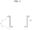
- FIG. 2 illustrates an enlarged cross-sectional view of one cylindrical member of FIG. 1
- FIG. 3 illustrates a cross-sectional view of a nuclear reactor decommissioning system according to an embodiment.
- a nuclear reactor decommissioning system includes a cutting device 300 for cutting a reactor 200, a lifting device 10 for lifting the reactor 200, a shielding device 40 for blocking diffusion of radioactive dust 1 generated while cutting the reactor 200, a dust blocking device 400 for blocking bioprotective concrete 100 surrounding the reactor 200 from the outside, and a dust collecting device 500 for collecting the radioactive dust 1.
- the cutting device 300 may include a thermal cutting device, a mechanical cutting device such as a wire saw, or an electrical cutting device such as a laser.
- the cutting device is not limited thereto, and various devices that may cut the reactor are applicable thereto.
- the lifting device 10 may be inserted into the reactor 200 to lift the reactor 200.
- the lifting device 10 may include a coupling member 11 coupled to a coupling protrusion 200a to be protruded inside the reactor 200, and an elevating device 12 connected to the coupling member 11 and lifting the reactor 200.
- the coupling member 11 has a disk-like shape. However, it is not limited thereto, and various shapes that may be inserted inside the reactor 200 to be combined with the reactor 200 are applicable.
- the elevating device 12 may have a rod-like shape that is connected to a central portion of the disk-shaped coupling member 11 to lift the coupling member 11 together.
- the shielding device 40 is positioned between the reactor 200 and the lifting device 10 to be able to block the diffusion of the radioactive dust 1 generated by the cutting device 300 that cuts an upper end portion 210 of the reactor 200.
- the shielding device 40 may include a shielding tube 20 including a plurality of cylindrical members 21a, 21b, 21c, 21d, 21e, and 21f of different diameters surrounding the elevating device 12, and a shielding plate 30 positioned on an upper portion of the shielding tube 20 and blocking the reactor 200 from the outside.
- the shielding tube 20 is shown as consisting of six cylindrical members 21a, 21b, 21c, 21d, 21e, and 21 f, but is not limited thereto, and it may be configured of cylindrical members in various numbers.
- a plurality of cylindrical members 21a, 21b, 21c, 21d, 21e, and 21f forming the shielding tube 20 may have a larger diameter as a distance from the elevating device 12 increases. Accordingly, as shown in FIG. 1 , the shielding tube 20 may have a stepped shape as a whole when it is not in contact with the elevating device 12 of the lifting device 10.
- respective end portions of the cylindrical members 21a, 21b, 21c, 21d, 21e, and 21f may have a catching projection 4 to be locked to respective end portions of adjacent cylindrical members 21a, 21b, 21c, 21d, 21e, and 21f.
- the catching projection 4 may include an outer catching projection 6 extending from the cylindrical member 21b to the outside, and an inner catching projection 5 extending from the cylindrical member 21b to the inside.
- the outer catching projection 6 may be positioned at an upper end portion of the cylindrical member 21b
- the inner catching projection 5 may be positioned at a lower end portion of the cylindrical member 21b, based on a direction of gravity.
- the inner catching projection 5 and the outer catching projection 6 of the adjacent cylindrical members 21a, 21b, 21c, 21d, 21e, and 21f contact each other, so that the shielding tube 20 has a entirely step shape by gravity.
- the shielding device 40 may block the radioactive dust 1 such as slag, fume gas, and aerosol from contaminating the lifting device 10.
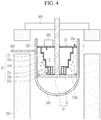
- FIG. 4 illustrates a cross-sectional view of one step of decommissioning a reactor using a nuclear reactor decommissioning system according to an embodiment
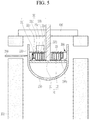
- FIG. 5 illustrates a cross-sectional view of a step after that of FIG. 4 .
- the length of the shielding tube 20 has a length of L1, but as shown in FIG. 4 , when the reactor 200 is lifted, the length of the shielding tube 20 may have a length of L2 that is smaller than L1.
- the cylindrical members 21a, 21b, 21c, 21d, 21e, and 21f of the shielding tube 20 are sequentially lifted together with the elevating device 12 from the cylindrical member closest to the elevating device 12. That is, as shown in FIG. 4 , the three cylindrical members 21a, 21b, and 21c closest to the elevating device 12 among the six cylindrical members are first lifted to overlap each other.
- the shielding device 40 may be easily inserted between the elevating device 12 and the reactor 200.
- the shielding plate 30 may include a plurality of ventilation parts 30a positioned between the reactor 200 and the outermost cylindrical member 21f of the shielding tube 20. As shown in FIG. 3 , the plurality of ventilation parts 30a may be formed along an edge of the shielding plate 30.
- the shielding plate 30 may be rotated around the elevating device 12 as a central axis. Accordingly, since a position of the ventilation part 30a may be adjusted, the radioactive dust 1 may be effectively collected by adjusting the position of the ventilation part 30a according to an amount of the radioactive dust 1.
- the dust blocking device 400 may block the bioprotective concrete 100 surrounding the reactor 200 from the outside.
- the dust collecting device 500 may be connected to the plurality of ventilation parts 30a to collect the radioactive dust 1 collected through the ventilation parts 30a.
- the dust collecting device 500 is installed on the shielding plate 30, but is not limited thereto, and may be installed at various positions.
Landscapes
- Physics & Mathematics (AREA)
- Engineering & Computer Science (AREA)
- General Engineering & Computer Science (AREA)
- High Energy & Nuclear Physics (AREA)
- Plasma & Fusion (AREA)
- Working Measures On Existing Buildindgs (AREA)
Abstract
Description
- The present invention relates to a nuclear reactor decommissioning system.
- As fossil energy is depleted worldwide, nuclear power generation is being used as a major energy source. In such nuclear power generation, a generally-used pressurized water reactor (PWR) nuclear power plant consists of a primary system circulating through a nuclear reactor, a secondary system circulating through a steam generator, and a tertiary system circulating through a condenser. Specifically, in the primary system, pressure is applied to a coolant in a reactor to maintain a pressure of 150 atm and 300 °C, and in the secondary system, the coolant passes through tubes of a steam generator and boils water of the steam generator side to generate steam to turn a turbine. In the tertiary system, the steam turns the turbine, and then passes through the condenser and becomes water again and is sent to the steam generator.
- Since the reactor of such a pressurized water reactor type of nuclear power plant is contaminated with radioactivity, when the reactor is cut and dismantled, radioactive dust such as aerosol and slag may diffuse and contaminate peripheral devices.
- The present embodiment relates to a nuclear reactor decommissioning system that may prevent contamination of peripheral devices by radioactive dust generated during a decommissioning process thereof.
- A nuclear reactor decommissioning system according to an embodiment includes: a cutting device to cut a reactor, a lifting device inserted inside the reactor to lift the reactor, and a shielding device that is positioned between the reactor and the lifting device and blocks radioactive dust generated by the cutting device from spreading.
- The lifting device may include a coupling member coupled to the reactor, and an elevating device that is connected to the coupling member and elevates the reactor, and the shielding device may include a shielding tube including a plurality of cylindrical members of different diameters surrounding the elevating device, and a shielding plate positioned on an upper portion of the shielding tube and blocking the reactor from the outside.
- The plurality of cylindrical members may have a larger diameter as a distance from the elevating device increases, and respective end portions of the cylindrical member may have catching projections to be caught by respective end portions of adjacent cylindrical member.
- The catching projection may include an outer catching projection extending from the cylindrical member to the outside, and an inner catching projection extending from the cylindrical member to the inside.
- When the reactor is lifted by the lifting device, at least some of the cylindrical members of the shielding tube may be lifted together.
- The shielding plate may include a plurality of ventilation parts positioned between the reactor and the outermost cylindrical member of the shielding tube.
- The plurality of ventilation parts may be formed along an edge of the shielding plate.
- A dust collecting device connected to the plurality of ventilation parts to collect the radioactive dust may be further included.
- According to the embodiment, it is possible to easily adjust a length of a shielding device according to a cutting process of a reactor, by installing a length-adjustable shielding device between the reactor and a lifting device. Therefore, diffusion of radioactive dust generated by a cutting device for cutting the reactor may be easily blocked.
- In addition, it is possible to minimize radioactive dust from contaminating a peripheral device or being exposed to a worker, by intensively collecting the radioactive dust through a ventilation part formed on a shielding plate.
-
-
FIG. 1 illustrates a cross-sectional view of a nuclear reactor decommissioning system according to an embodiment. -
FIG. 2 illustrates an enlarged cross-sectional view of one cylindrical member ofFIG. 1 . -
FIG. 3 illustrates a cross-sectional view of a nuclear reactor decommissioning system according to an embodiment. -
FIG. 4 illustrates a cross-sectional view of one step of decommissioning a reactor using a nuclear reactor decommissioning system according to an embodiment. -
FIG. 5 illustrates a cross-sectional view of a step after that ofFIG. 4 . - The present invention will be described more fully hereinafter with reference to the accompanying drawings, in which embodiments of the invention are shown. As those skilled in the art would realize, the described embodiment may be modified in various different ways, all without departing from the scope of the present invention.
- In order to clearly describe the present invention, parts that are irrelevant to the description are omitted, and identical or similar constituent elements throughout the specification are denoted by the same reference numerals.
- Further, in the drawings, the size and thickness of each element are arbitrarily illustrated for ease of description, and the present disclosure is not necessarily limited to those illustrated in the drawings.
-
FIG. 1 illustrates a cross-sectional view of a nuclear reactor decommissioning system according to an embodiment,FIG. 2 illustrates an enlarged cross-sectional view of one cylindrical member ofFIG. 1 , andFIG. 3 illustrates a cross-sectional view of a nuclear reactor decommissioning system according to an embodiment. - As shown in
FIG. 1 to FIG. 3 , a nuclear reactor decommissioning system according to an embodiment includes acutting device 300 for cutting areactor 200, alifting device 10 for lifting thereactor 200, ashielding device 40 for blocking diffusion ofradioactive dust 1 generated while cutting thereactor 200, adust blocking device 400 for blockingbioprotective concrete 100 surrounding thereactor 200 from the outside, and adust collecting device 500 for collecting theradioactive dust 1. - The
cutting device 300 may include a thermal cutting device, a mechanical cutting device such as a wire saw, or an electrical cutting device such as a laser. However, the cutting device is not limited thereto, and various devices that may cut the reactor are applicable thereto. - The
lifting device 10 may be inserted into thereactor 200 to lift thereactor 200. Thelifting device 10 may include acoupling member 11 coupled to acoupling protrusion 200a to be protruded inside thereactor 200, and anelevating device 12 connected to thecoupling member 11 and lifting thereactor 200. - The
coupling member 11 has a disk-like shape. However, it is not limited thereto, and various shapes that may be inserted inside thereactor 200 to be combined with thereactor 200 are applicable. - The
elevating device 12 may have a rod-like shape that is connected to a central portion of the disk-shaped coupling member 11 to lift thecoupling member 11 together. - The
shielding device 40 is positioned between thereactor 200 and thelifting device 10 to be able to block the diffusion of theradioactive dust 1 generated by thecutting device 300 that cuts anupper end portion 210 of thereactor 200. Theshielding device 40 may include ashielding tube 20 including a plurality ofcylindrical members elevating device 12, and ashielding plate 30 positioned on an upper portion of theshielding tube 20 and blocking thereactor 200 from the outside. - In the present embodiment, the
shielding tube 20 is shown as consisting of sixcylindrical members - A plurality of
cylindrical members shielding tube 20 may have a larger diameter as a distance from theelevating device 12 increases. Accordingly, as shown inFIG. 1 , theshielding tube 20 may have a stepped shape as a whole when it is not in contact with theelevating device 12 of thelifting device 10. - As shown in
FIG. 1 andFIG. 2 , respective end portions of thecylindrical members catching projection 4 to be locked to respective end portions of adjacentcylindrical members FIG. 2 , onecylindrical member 21b will be mainly described in detail. As shown inFIG. 2 , thecatching projection 4 may include an outercatching projection 6 extending from thecylindrical member 21b to the outside, and an inner catching projection 5 extending from thecylindrical member 21b to the inside. In the present embodiment, the outercatching projection 6 may be positioned at an upper end portion of thecylindrical member 21b, and the inner catching projection 5 may be positioned at a lower end portion of thecylindrical member 21b, based on a direction of gravity. - Therefore, as shown in
FIG. 1 , the inner catching projection 5 and the outercatching projection 6 of the adjacentcylindrical members shielding tube 20 has a entirely step shape by gravity. - Therefore, even if the
reactor 200 is cut by using thecutting device 300, theshielding device 40 may block theradioactive dust 1 such as slag, fume gas, and aerosol from contaminating thelifting device 10. -
FIG. 4 illustrates a cross-sectional view of one step of decommissioning a reactor using a nuclear reactor decommissioning system according to an embodiment, andFIG. 5 illustrates a cross-sectional view of a step after that ofFIG. 4 . - As shown in
FIG. 4 , when thereactor 200 is lifted by using thelifting device 10 in order to cut amiddle portion 220 of thereactor 200 by using thecutting device 300, at least some of thecylindrical members shielding tube 20 are lifted together. That is, some (21a, 21b, and 21c) of the cylindrical members contacting thecoupling member 11 of thelifting device 10 are lifted together with thelifting device 10. Therefore, some (21a, 21b, and 21c) of the cylindrical members overlap each other, so that a length of theshielding tube 20 may be shortened. - That is, in
FIG. 1 , the length of theshielding tube 20 has a length of L1, but as shown inFIG. 4 , when thereactor 200 is lifted, the length of theshielding tube 20 may have a length of L2 that is smaller than L1. - In this case, the
cylindrical members shielding tube 20 are sequentially lifted together with theelevating device 12 from the cylindrical member closest to theelevating device 12. That is, as shown inFIG. 4 , the threecylindrical members elevating device 12 among the six cylindrical members are first lifted to overlap each other. However, it is not limited thereto, and various numbers of cylindrical members may overlap each other depending on an elevation height of thereactor 200. - In addition, as shown in
FIG. 5 , when thereactor 200 is further lifted to cut alower end portion 230 of thereactor 200, all of thecylindrical members shielding tube 20 overlap each other. Therefore, a length L3 of theshielding tube 20 further decreases. - As such, in the case of cutting from the upper end portion to the lower end portion of the
reactor 200 while lifting thereactor 200, since the length of theshielding device 40 that blocks theelevating device 12 from theradioactive dust 1 may also be shortened, theshielding device 40 may be easily inserted between theelevating device 12 and thereactor 200. - The shielding
plate 30 may include a plurality ofventilation parts 30a positioned between thereactor 200 and the outermostcylindrical member 21f of the shieldingtube 20. As shown inFIG. 3 , the plurality ofventilation parts 30a may be formed along an edge of the shieldingplate 30. The shieldingplate 30 may be rotated around the elevatingdevice 12 as a central axis. Accordingly, since a position of theventilation part 30a may be adjusted, theradioactive dust 1 may be effectively collected by adjusting the position of theventilation part 30a according to an amount of theradioactive dust 1. - The
dust blocking device 400 may block thebioprotective concrete 100 surrounding thereactor 200 from the outside. - The
dust collecting device 500 may be connected to the plurality ofventilation parts 30a to collect theradioactive dust 1 collected through theventilation parts 30a. In the present embodiment, thedust collecting device 500 is installed on the shieldingplate 30, but is not limited thereto, and may be installed at various positions. - Therefore, it is possible to minimize the
radioactive dust 1 from contaminating peripheral devices or being exposed to workers, by intensively collecting theradioactive dust 1 through theventilation parts 30a formed on the shieldingplate 30. - While this invention has been described in connection with what is presently considered to be practical exemplary embodiments, it is to be understood that the invention is not limited to the disclosed embodiments, but, on the contrary, is intended to cover various modifications and equivalent arrangements included within the scope of the appended claims.
Claims (8)
- A nuclear reactor decommissioning system, comprising
a cutting device to cut a reactor,
a lifting device inserted inside the reactor to lift the reactor, and
a shielding device that is positioned between the reactor and the lifting device and blocks radioactive dust generated by the cutting device from spreading. - The nuclear reactor decommissioning system of claim 1, wherein
the lifting device includes
a coupling member coupled to the reactor, and
an elevating device that is connected to the coupling member and elevates the reactor, and
the shielding device includes
a shielding tube including a plurality of cylindrical members of different diameters surrounding the elevating device, and
a shielding plate positioned on an upper portion of the shielding tube and blocking the reactor from the outside. - The nuclear reactor decommissioning system of claim 2, wherein
the plurality of cylindrical members have a larger diameter as a distance from the elevating device increases, and
respective end portions of the cylindrical member have catching projections to be caught by respective end portions of adjacent cylindrical members. - The nuclear reactor decommissioning system of claim 3, wherein
the catching projection includes
an outer catching projection extending from the cylindrical member to the outside, and
an inner catching projection extending from the cylindrical member to the inside. - The nuclear reactor decommissioning system of claim 3, wherein
when the reactor is lifted by the lifting device, at least some of the cylindrical members of the shielding tube are lifted together. - The nuclear reactor decommissioning system of claim 2, wherein
the shielding plate includes a plurality of ventilation parts positioned between the reactor and the outermost cylindrical member of the shielding tube. - The nuclear reactor decommissioning system of claim 2, wherein
the plurality of ventilation parts are formed along an edge of the shielding plate. - The nuclear reactor decommissioning system of claim 2, further comprising
a dust collecting device connected to the plurality of ventilation parts to collect the radioactive dust.
Applications Claiming Priority (2)
| Application Number | Priority Date | Filing Date | Title |
|---|---|---|---|
| KR1020180078939A KR102080906B1 (en) | 2018-07-06 | 2018-07-06 | Reactor dismantling apparatus |
| PCT/KR2019/008124 WO2020009468A1 (en) | 2018-07-06 | 2019-07-03 | Nuclear reactor decommissioning system |
Publications (3)
| Publication Number | Publication Date |
|---|---|
| EP3819917A1 true EP3819917A1 (en) | 2021-05-12 |
| EP3819917A4 EP3819917A4 (en) | 2022-04-06 |
| EP3819917B1 EP3819917B1 (en) | 2025-04-23 |
Family
ID=69060173
Family Applications (1)
| Application Number | Title | Priority Date | Filing Date |
|---|---|---|---|
| EP19831384.3A Active EP3819917B1 (en) | 2018-07-06 | 2019-07-03 | Nuclear reactor decommissioning system |
Country Status (5)
| Country | Link |
|---|---|
| US (1) | US11342087B2 (en) |
| EP (1) | EP3819917B1 (en) |
| JP (1) | JP7152603B2 (en) |
| KR (1) | KR102080906B1 (en) |
| WO (1) | WO2020009468A1 (en) |
Families Citing this family (1)
| Publication number | Priority date | Publication date | Assignee | Title |
|---|---|---|---|---|
| KR102570118B1 (en) * | 2021-01-14 | 2023-08-22 | 한국수력원자력 주식회사 | System for decommissioning nuclear facilities |
Family Cites Families (17)
| Publication number | Priority date | Publication date | Assignee | Title |
|---|---|---|---|---|
| JPS60251990A (en) | 1984-05-28 | 1985-12-12 | Toyo Jitsugyo Kk | Contact material for water treatment and preparation thereof |
| US4919881A (en) | 1988-07-05 | 1990-04-24 | Westinghouse Electric Corp. | Reactor internals through-hole grapple |
| JP3597570B2 (en) | 1994-09-07 | 2004-12-08 | 東芝プラントシステム株式会社 | Reactor dismantling method and apparatus |
| JP2987070B2 (en) * | 1995-03-02 | 1999-12-06 | 株式会社日立製作所 | Method of cutting the structure inside the reactor pressure vessel |
| JP3435270B2 (en) * | 1995-11-28 | 2003-08-11 | 株式会社日立製作所 | How to bring in the reactor pressure vessel |
| JPH1090493A (en) * | 1996-09-12 | 1998-04-10 | Fuji Electric Co Ltd | Remote dismantling equipment for nuclear reactors |
| JPH10111397A (en) * | 1996-10-03 | 1998-04-28 | Mitsubishi Heavy Ind Ltd | Tank dismounting method |
| JP2000206294A (en) * | 1999-01-14 | 2000-07-28 | Hitachi Ltd | How to carry out large equipment |
| KR100631472B1 (en) * | 2004-07-30 | 2006-10-11 | 주식회사 우진산업개발 | Hydraulic sluice structure |
| JP2006084178A (en) * | 2004-09-14 | 2006-03-30 | Hitachi Ltd | Nuclear facility refueling machine |
| JP5464550B2 (en) | 2010-10-26 | 2014-04-09 | 東芝プラントシステム株式会社 | Method and apparatus for dismantling reactor pressure vessel |
| KR101188680B1 (en) * | 2010-12-23 | 2012-10-09 | 한국수력원자력 주식회사 | Solidification method of radioactive waste accompanying chloride recycling or radioactive iodide removing and the device thereof |
| JP2012230084A (en) | 2011-04-27 | 2012-11-22 | Shimizu Corp | Method for dismantling nuclear power generation plant building |
| JP6129656B2 (en) * | 2013-06-20 | 2017-05-17 | 日立Geニュークリア・エナジー株式会社 | Method for carrying out fuel debris and working house system in boiling water nuclear power plant |
| KR101503288B1 (en) | 2013-10-31 | 2015-03-18 | 티더블유앤씨(주) | Collecting device for a nuclear power plant |
| KR20150138126A (en) * | 2015-08-21 | 2015-12-09 | 이우성 | Nuclear Waste double block structure, the dust collector tank boiling water reactor nuclear power plant equipment for nuclear power plants |
| KR101754538B1 (en) * | 2016-08-02 | 2017-07-05 | 두산중공업 주식회사 | Method for dismantling Reactor Vessel Internal and Reactor Vessel |
-
2018
- 2018-07-06 KR KR1020180078939A patent/KR102080906B1/en active Active
-
2019
- 2019-07-03 US US17/257,360 patent/US11342087B2/en active Active
- 2019-07-03 WO PCT/KR2019/008124 patent/WO2020009468A1/en not_active Ceased
- 2019-07-03 EP EP19831384.3A patent/EP3819917B1/en active Active
- 2019-07-03 JP JP2021520897A patent/JP7152603B2/en active Active
Also Published As
| Publication number | Publication date |
|---|---|
| EP3819917A4 (en) | 2022-04-06 |
| JP7152603B2 (en) | 2022-10-12 |
| JP2021529327A (en) | 2021-10-28 |
| KR102080906B1 (en) | 2020-02-24 |
| US20210183531A1 (en) | 2021-06-17 |
| KR20200010673A (en) | 2020-01-31 |
| EP3819917B1 (en) | 2025-04-23 |
| US11342087B2 (en) | 2022-05-24 |
| WO2020009468A1 (en) | 2020-01-09 |
Similar Documents
| Publication | Publication Date | Title |
|---|---|---|
| JP5607288B2 (en) | Nuclear fuel spacer assembly with debris guide | |
| JP2016503179A (en) | Apparatus and method for removing an upper reactor structure from a reactor pressure vessel | |
| US11342087B2 (en) | Nuclear reactor decommissioning system | |
| JPS6252840B2 (en) | ||
| US11823806B2 (en) | Nuclear reactor dismantlement system | |
| US4667547A (en) | Apparatus and method for removing a top nozzle in reconstituting a fuel assembly | |
| GB2081961A (en) | Spacer grid for a nuclear reactor fuel assembly | |
| KR102164593B1 (en) | Reactor dismantling apparatus | |
| JPS6352355B2 (en) | ||
| US3697375A (en) | Fuel assembly for insertion from above into a nuclear reactor core | |
| US11715573B2 (en) | Decommissioning method of biodegradable concrete of PWR type nuclear power plant | |
| KR101687119B1 (en) | A cutting tool for control rod of reactor control element assembly | |
| KR20220102884A (en) | System for decommissioning nuclear facilities | |
| JPH0545151B2 (en) | ||
| JP7052077B2 (en) | Systems and methods for dismantling and decontaminating bioprotective concrete in pressurized light water reactor nuclear power plants | |
| KR102249496B1 (en) | Reactor dismantling system | |
| EP1993104B1 (en) | Method for dismantling heat exchanger installed in building for nuclear reactor | |
| EP0222623B1 (en) | Fixture for rectifying guide-thimble damage in reconstitutable nuclear fuel assemblies | |
| US11984233B2 (en) | Method for decommissioning heavy water reactor facility | |
| US10413961B2 (en) | Method for manufacturing cylindrical member | |
| KR102035852B1 (en) | Decommissioning method of biodegradable concrete of pwr type nuclear power plant | |
| KR101149550B1 (en) | Top nozzle assembly for nuclear fuel assembly | |
| KR102587913B1 (en) | Reactor dismantling apparatus | |
| JP4343852B2 (en) | Removal method of thimble tube from fuel assembly and removal equipment | |
| JPH0229199B2 (en) |
Legal Events
| Date | Code | Title | Description |
|---|---|---|---|
| STAA | Information on the status of an ep patent application or granted ep patent |
Free format text: STATUS: THE INTERNATIONAL PUBLICATION HAS BEEN MADE |
|
| PUAI | Public reference made under article 153(3) epc to a published international application that has entered the european phase |
Free format text: ORIGINAL CODE: 0009012 |
|
| STAA | Information on the status of an ep patent application or granted ep patent |
Free format text: STATUS: REQUEST FOR EXAMINATION WAS MADE |
|
| 17P | Request for examination filed |
Effective date: 20210203 |
|
| AK | Designated contracting states |
Kind code of ref document: A1 Designated state(s): AL AT BE BG CH CY CZ DE DK EE ES FI FR GB GR HR HU IE IS IT LI LT LU LV MC MK MT NL NO PL PT RO RS SE SI SK SM TR |
|
| DAV | Request for validation of the european patent (deleted) | ||
| DAX | Request for extension of the european patent (deleted) | ||
| A4 | Supplementary search report drawn up and despatched |
Effective date: 20220309 |
|
| RIC1 | Information provided on ipc code assigned before grant |
Ipc: G21F 9/28 20060101ALI20220302BHEP Ipc: G21F 7/06 20060101ALI20220302BHEP Ipc: G21C 1/08 20060101ALI20220302BHEP Ipc: G21D 1/00 20060101AFI20220302BHEP |
|
| GRAP | Despatch of communication of intention to grant a patent |
Free format text: ORIGINAL CODE: EPIDOSNIGR1 |
|
| STAA | Information on the status of an ep patent application or granted ep patent |
Free format text: STATUS: GRANT OF PATENT IS INTENDED |
|
| INTG | Intention to grant announced |
Effective date: 20241121 |
|
| GRAS | Grant fee paid |
Free format text: ORIGINAL CODE: EPIDOSNIGR3 |
|
| GRAA | (expected) grant |
Free format text: ORIGINAL CODE: 0009210 |
|
| STAA | Information on the status of an ep patent application or granted ep patent |
Free format text: STATUS: THE PATENT HAS BEEN GRANTED |
|
| AK | Designated contracting states |
Kind code of ref document: B1 Designated state(s): AL AT BE BG CH CY CZ DE DK EE ES FI FR GB GR HR HU IE IS IT LI LT LU LV MC MK MT NL NO PL PT RO RS SE SI SK SM TR |
|
| REG | Reference to a national code |
Ref country code: GB Ref legal event code: FG4D |
|
| REG | Reference to a national code |
Ref country code: CH Ref legal event code: EP |
|
| REG | Reference to a national code |
Ref country code: DE Ref legal event code: R096 Ref document number: 602019069089 Country of ref document: DE |
|
| REG | Reference to a national code |
Ref country code: IE Ref legal event code: FG4D |
|
| REG | Reference to a national code |
Ref country code: NL Ref legal event code: MP Effective date: 20250423 |
|
| PG25 | Lapsed in a contracting state [announced via postgrant information from national office to epo] |
Ref country code: NL Free format text: LAPSE BECAUSE OF FAILURE TO SUBMIT A TRANSLATION OF THE DESCRIPTION OR TO PAY THE FEE WITHIN THE PRESCRIBED TIME-LIMIT Effective date: 20250423 |
|
| REG | Reference to a national code |
Ref country code: AT Ref legal event code: MK05 Ref document number: 1788628 Country of ref document: AT Kind code of ref document: T Effective date: 20250423 |
|
| PG25 | Lapsed in a contracting state [announced via postgrant information from national office to epo] |
Ref country code: PT Free format text: LAPSE BECAUSE OF FAILURE TO SUBMIT A TRANSLATION OF THE DESCRIPTION OR TO PAY THE FEE WITHIN THE PRESCRIBED TIME-LIMIT Effective date: 20250825 Ref country code: FI Free format text: LAPSE BECAUSE OF FAILURE TO SUBMIT A TRANSLATION OF THE DESCRIPTION OR TO PAY THE FEE WITHIN THE PRESCRIBED TIME-LIMIT Effective date: 20250423 Ref country code: ES Free format text: LAPSE BECAUSE OF FAILURE TO SUBMIT A TRANSLATION OF THE DESCRIPTION OR TO PAY THE FEE WITHIN THE PRESCRIBED TIME-LIMIT Effective date: 20250423 |
|
| PGFP | Annual fee paid to national office [announced via postgrant information from national office to epo] |
Ref country code: DE Payment date: 20250702 Year of fee payment: 7 |
|
| REG | Reference to a national code |
Ref country code: LT Ref legal event code: MG9D |
|
| PG25 | Lapsed in a contracting state [announced via postgrant information from national office to epo] |
Ref country code: GR Free format text: LAPSE BECAUSE OF FAILURE TO SUBMIT A TRANSLATION OF THE DESCRIPTION OR TO PAY THE FEE WITHIN THE PRESCRIBED TIME-LIMIT Effective date: 20250724 Ref country code: NO Free format text: LAPSE BECAUSE OF FAILURE TO SUBMIT A TRANSLATION OF THE DESCRIPTION OR TO PAY THE FEE WITHIN THE PRESCRIBED TIME-LIMIT Effective date: 20250723 |
|
| PG25 | Lapsed in a contracting state [announced via postgrant information from national office to epo] |
Ref country code: PL Free format text: LAPSE BECAUSE OF FAILURE TO SUBMIT A TRANSLATION OF THE DESCRIPTION OR TO PAY THE FEE WITHIN THE PRESCRIBED TIME-LIMIT Effective date: 20250423 |
|
| PG25 | Lapsed in a contracting state [announced via postgrant information from national office to epo] |
Ref country code: BG Free format text: LAPSE BECAUSE OF FAILURE TO SUBMIT A TRANSLATION OF THE DESCRIPTION OR TO PAY THE FEE WITHIN THE PRESCRIBED TIME-LIMIT Effective date: 20250423 |
|
| PG25 | Lapsed in a contracting state [announced via postgrant information from national office to epo] |
Ref country code: HR Free format text: LAPSE BECAUSE OF FAILURE TO SUBMIT A TRANSLATION OF THE DESCRIPTION OR TO PAY THE FEE WITHIN THE PRESCRIBED TIME-LIMIT Effective date: 20250423 |
|
| PG25 | Lapsed in a contracting state [announced via postgrant information from national office to epo] |
Ref country code: AT Free format text: LAPSE BECAUSE OF FAILURE TO SUBMIT A TRANSLATION OF THE DESCRIPTION OR TO PAY THE FEE WITHIN THE PRESCRIBED TIME-LIMIT Effective date: 20250423 |
|
| PG25 | Lapsed in a contracting state [announced via postgrant information from national office to epo] |
Ref country code: RS Free format text: LAPSE BECAUSE OF FAILURE TO SUBMIT A TRANSLATION OF THE DESCRIPTION OR TO PAY THE FEE WITHIN THE PRESCRIBED TIME-LIMIT Effective date: 20250723 |
|
| PG25 | Lapsed in a contracting state [announced via postgrant information from national office to epo] |
Ref country code: IS Free format text: LAPSE BECAUSE OF FAILURE TO SUBMIT A TRANSLATION OF THE DESCRIPTION OR TO PAY THE FEE WITHIN THE PRESCRIBED TIME-LIMIT Effective date: 20250823 |
|
| PG25 | Lapsed in a contracting state [announced via postgrant information from national office to epo] |
Ref country code: LV Free format text: LAPSE BECAUSE OF FAILURE TO SUBMIT A TRANSLATION OF THE DESCRIPTION OR TO PAY THE FEE WITHIN THE PRESCRIBED TIME-LIMIT Effective date: 20250423 |
|
| PG25 | Lapsed in a contracting state [announced via postgrant information from national office to epo] |
Ref country code: SM Free format text: LAPSE BECAUSE OF FAILURE TO SUBMIT A TRANSLATION OF THE DESCRIPTION OR TO PAY THE FEE WITHIN THE PRESCRIBED TIME-LIMIT Effective date: 20250423 Ref country code: DK Free format text: LAPSE BECAUSE OF FAILURE TO SUBMIT A TRANSLATION OF THE DESCRIPTION OR TO PAY THE FEE WITHIN THE PRESCRIBED TIME-LIMIT Effective date: 20250423 |
|
| PG25 | Lapsed in a contracting state [announced via postgrant information from national office to epo] |
Ref country code: CZ Free format text: LAPSE BECAUSE OF FAILURE TO SUBMIT A TRANSLATION OF THE DESCRIPTION OR TO PAY THE FEE WITHIN THE PRESCRIBED TIME-LIMIT Effective date: 20250423 |
|
| PG25 | Lapsed in a contracting state [announced via postgrant information from national office to epo] |
Ref country code: EE Free format text: LAPSE BECAUSE OF FAILURE TO SUBMIT A TRANSLATION OF THE DESCRIPTION OR TO PAY THE FEE WITHIN THE PRESCRIBED TIME-LIMIT Effective date: 20250423 |
|
| REG | Reference to a national code |
Ref country code: DE Ref legal event code: R097 Ref document number: 602019069089 Country of ref document: DE |
|
| PG25 | Lapsed in a contracting state [announced via postgrant information from national office to epo] |
Ref country code: RO Free format text: LAPSE BECAUSE OF FAILURE TO SUBMIT A TRANSLATION OF THE DESCRIPTION OR TO PAY THE FEE WITHIN THE PRESCRIBED TIME-LIMIT Effective date: 20250423 Ref country code: SK Free format text: LAPSE BECAUSE OF FAILURE TO SUBMIT A TRANSLATION OF THE DESCRIPTION OR TO PAY THE FEE WITHIN THE PRESCRIBED TIME-LIMIT Effective date: 20250423 |
|
| PG25 | Lapsed in a contracting state [announced via postgrant information from national office to epo] |
Ref country code: IT Free format text: LAPSE BECAUSE OF FAILURE TO SUBMIT A TRANSLATION OF THE DESCRIPTION OR TO PAY THE FEE WITHIN THE PRESCRIBED TIME-LIMIT Effective date: 20250423 |
|
| REG | Reference to a national code |
Ref country code: CH Ref legal event code: H13 Free format text: ST27 STATUS EVENT CODE: U-0-0-H10-H13 (AS PROVIDED BY THE NATIONAL OFFICE) Effective date: 20260224 |
|
| PLBE | No opposition filed within time limit |
Free format text: ORIGINAL CODE: 0009261 |
|
| STAA | Information on the status of an ep patent application or granted ep patent |
Free format text: STATUS: NO OPPOSITION FILED WITHIN TIME LIMIT |
|
| REG | Reference to a national code |
Ref country code: CH Ref legal event code: L10 Free format text: ST27 STATUS EVENT CODE: U-0-0-L10-L00 (AS PROVIDED BY THE NATIONAL OFFICE) Effective date: 20260304 |
|
| PG25 | Lapsed in a contracting state [announced via postgrant information from national office to epo] |
Ref country code: LU Free format text: LAPSE BECAUSE OF NON-PAYMENT OF DUE FEES Effective date: 20250703 |
|
| GBPC | Gb: european patent ceased through non-payment of renewal fee |
Effective date: 20250723 |
|
| REG | Reference to a national code |
Ref country code: BE Ref legal event code: MM Effective date: 20250731 |
|
| 26N | No opposition filed |
Effective date: 20260126 |
|
| PG25 | Lapsed in a contracting state [announced via postgrant information from national office to epo] |
Ref country code: GB Free format text: LAPSE BECAUSE OF NON-PAYMENT OF DUE FEES Effective date: 20250723 |
|
| PG25 | Lapsed in a contracting state [announced via postgrant information from national office to epo] |
Ref country code: BE Free format text: LAPSE BECAUSE OF NON-PAYMENT OF DUE FEES Effective date: 20250731 |
|
| PG25 | Lapsed in a contracting state [announced via postgrant information from national office to epo] |
Ref country code: FR Free format text: LAPSE BECAUSE OF NON-PAYMENT OF DUE FEES Effective date: 20250731 |
|
| PG25 | Lapsed in a contracting state [announced via postgrant information from national office to epo] |
Ref country code: CH Free format text: LAPSE BECAUSE OF NON-PAYMENT OF DUE FEES Effective date: 20250731 |