EP3819733B1 - Erzeugung eines digitalen zwillings aus einem mechanischen modell - Google Patents
Erzeugung eines digitalen zwillings aus einem mechanischen modell Download PDFInfo
- Publication number
- EP3819733B1 EP3819733B1 EP20204067.1A EP20204067A EP3819733B1 EP 3819733 B1 EP3819733 B1 EP 3819733B1 EP 20204067 A EP20204067 A EP 20204067A EP 3819733 B1 EP3819733 B1 EP 3819733B1
- Authority
- EP
- European Patent Office
- Prior art keywords
- mechanical
- cad
- metadata
- simulation
- model
- Prior art date
- Legal status (The legal status is an assumption and is not a legal conclusion. Google has not performed a legal analysis and makes no representation as to the accuracy of the status listed.)
- Active
Links
Images


Classifications
-
- G—PHYSICS
- G05—CONTROLLING; REGULATING
- G05B—CONTROL OR REGULATING SYSTEMS IN GENERAL; FUNCTIONAL ELEMENTS OF SUCH SYSTEMS; MONITORING OR TESTING ARRANGEMENTS FOR SUCH SYSTEMS OR ELEMENTS
- G05B19/00—Program-control systems
- G05B19/02—Program-control systems electric
- G05B19/418—Total factory control, i.e. centrally controlling a plurality of machines, e.g. direct or distributed numerical control [DNC], flexible manufacturing systems [FMS], integrated manufacturing systems [IMS] or computer integrated manufacturing [CIM]
- G05B19/41885—Total factory control, i.e. centrally controlling a plurality of machines, e.g. direct or distributed numerical control [DNC], flexible manufacturing systems [FMS], integrated manufacturing systems [IMS] or computer integrated manufacturing [CIM] characterised by modeling, simulation of the manufacturing system
-
- G—PHYSICS
- G05—CONTROLLING; REGULATING
- G05B—CONTROL OR REGULATING SYSTEMS IN GENERAL; FUNCTIONAL ELEMENTS OF SUCH SYSTEMS; MONITORING OR TESTING ARRANGEMENTS FOR SUCH SYSTEMS OR ELEMENTS
- G05B19/00—Program-control systems
- G05B19/02—Program-control systems electric
- G05B19/04—Program control other than numerical control, i.e. in sequence controllers or logic controllers
- G05B19/042—Program control other than numerical control, i.e. in sequence controllers or logic controllers using digital processors
-
- G—PHYSICS
- G06—COMPUTING OR CALCULATING; COUNTING
- G06F—ELECTRIC DIGITAL DATA PROCESSING
- G06F30/00—Computer-aided design [CAD]
- G06F30/10—Geometric CAD
- G06F30/12—Geometric CAD characterised by design entry means specially adapted for CAD, e.g. graphical user interfaces [GUI] specially adapted for CAD
-
- G—PHYSICS
- G06—COMPUTING OR CALCULATING; COUNTING
- G06F—ELECTRIC DIGITAL DATA PROCESSING
- G06F30/00—Computer-aided design [CAD]
- G06F30/10—Geometric CAD
- G06F30/17—Mechanical parametric or variational design
-
- G—PHYSICS
- G06—COMPUTING OR CALCULATING; COUNTING
- G06F—ELECTRIC DIGITAL DATA PROCESSING
- G06F30/00—Computer-aided design [CAD]
- G06F30/10—Geometric CAD
- G06F30/18—Network design, e.g. design based on topological or interconnect aspects of utility systems, piping, heating ventilation air conditioning [HVAC] or cabling
-
- G—PHYSICS
- G06—COMPUTING OR CALCULATING; COUNTING
- G06F—ELECTRIC DIGITAL DATA PROCESSING
- G06F30/00—Computer-aided design [CAD]
- G06F30/20—Design optimisation, verification or simulation
-
- G—PHYSICS
- G05—CONTROLLING; REGULATING
- G05B—CONTROL OR REGULATING SYSTEMS IN GENERAL; FUNCTIONAL ELEMENTS OF SUCH SYSTEMS; MONITORING OR TESTING ARRANGEMENTS FOR SUCH SYSTEMS OR ELEMENTS
- G05B2219/00—Program-control systems
- G05B2219/30—Nc systems
- G05B2219/32—Operator till task planning
- G05B2219/32352—Modular modeling, decompose large system in smaller systems to simulate
-
- G—PHYSICS
- G05—CONTROLLING; REGULATING
- G05B—CONTROL OR REGULATING SYSTEMS IN GENERAL; FUNCTIONAL ELEMENTS OF SUCH SYSTEMS; MONITORING OR TESTING ARRANGEMENTS FOR SUCH SYSTEMS OR ELEMENTS
- G05B2219/00—Program-control systems
- G05B2219/30—Nc systems
- G05B2219/32—Operator till task planning
- G05B2219/32354—Divide, analyse process into subprocesses, until elementary unit operations
-
- G—PHYSICS
- G06—COMPUTING OR CALCULATING; COUNTING
- G06F—ELECTRIC DIGITAL DATA PROCESSING
- G06F2111/00—Details relating to CAD techniques
- G06F2111/20—Configuration CAD, e.g. designing by assembling or positioning modules selected from libraries of predesigned modules
-
- Y—GENERAL TAGGING OF NEW TECHNOLOGICAL DEVELOPMENTS; GENERAL TAGGING OF CROSS-SECTIONAL TECHNOLOGIES SPANNING OVER SEVERAL SECTIONS OF THE IPC; TECHNICAL SUBJECTS COVERED BY FORMER USPC CROSS-REFERENCE ART COLLECTIONS [XRACs] AND DIGESTS
- Y02—TECHNOLOGIES OR APPLICATIONS FOR MITIGATION OR ADAPTATION AGAINST CLIMATE CHANGE
- Y02P—CLIMATE CHANGE MITIGATION TECHNOLOGIES IN THE PRODUCTION OR PROCESSING OF GOODS
- Y02P90/00—Enabling technologies with a potential contribution to greenhouse gas [GHG] emissions mitigation
- Y02P90/02—Total factory control, e.g. smart factories, flexible manufacturing systems [FMS] or integrated manufacturing systems [IMS]
Definitions
- US 2017/053047 A1 relates to a computer-implemented technique of simulating automation applications based on input from a user that includes a computer creating a system design in a three-dimensional workspace based on one or more instructions provided by the user.
- WO 2016/053337 A1 relates to a technique for designing automation applications based on input from a user that includes a library interface, a three-dimensional workspace, a simulation engine, and controller code generation unit.
- the library interface is configured to receive a user selection of a plurality of components from a library of components.
- the three-dimensional workspace is configured to display the components and create a system design in the three-dimensional workspace using the components based on one or more instructions provided by the user.
- the simulation engine is configured to generate simulation code based on the system design in the three-dimensional workspace and execute the simulation code in response to a command from the user.
- EP 2 871 540 A2 relates to techniques to facilitate simulating machines used in industrial automation.
- An API is utilized to establish at least a communication link between a simulation model created in a simulation application and an industrial controller system outside of the simulation model, wherein the simulation model comprises definitions for a virtual representation of at least a portion of a machine used in an industrial automation environment.
- US 2014/180644 A1 relates to techniques for creating and running an industrial control system simulation.
- US 2009/089031 A1 relates to a tool for simulating an industrial control system.
- the tool includes a simulation component to emulate a controller according to a simulated execution environment and one or more simulation models for simulating devices associated with the controller, where the controller and the devices are integrated in a common simulation platform.
- DAHMEN ULRICH ET AL "Experimentable Digital Twins for a Modeling and Simulation-based Engineering Approach", 2018 IEEE INTERNATIONAL SYSTEMS ENGINEERING SYMPOSIUM (ISSE), IEEE, 1 October 2018, pages 1 to 8 , introduces a systematic approach for a methodology that connects the worlds from different engineering domains leading to a modeling and simulation-based engineering concept. Central aspect of this concept is the consequent application of modeling and simulation techniques at each stage of the development process to support both, the design and verification process.
- a system for developing automation system models comprising a user interface component configured to receive mechanical design input data; and a mechanical modeling component configured to generate a three-dimensional (3D) mechanical model of an industrial automation system based on the mechanical design input data, wherein the user interface component is further configured to receive aspect specification input data that labels selected elements of the 3D mechanical model as being specified aspects of the industrial automation system, and the executable components further comprise an aspect metadata component configured to assign aspect metadata to the selected elements in accordance with the aspect input data, the aspect metadata defining simulation behaviors of the selected elements to yield a digital twin of the industrial automation system capable of simulation within a simulation platform in accordance with the simulation behaviors.
- one or more embodiments provide a method for creating a simulation model of an industrial automation system, comprising receiving, by a computer-aided design (CAD) system, mechanical design input data; generating, by the CAD system, a three-dimensional (3D) mechanical model of an industrial automation system based on the mechanical design input data; receiving, by the CAD system, aspect specification input data that tags selected components of the 3D mechanical model as being specified aspects of the industrial automation system; and assigning, by the CAD system, aspect metadata to the selected components based on the aspect input data, the aspect metadata defining simulation behaviors of the selected components, wherein the assigning the aspect metadata converts the mechanical model to a digital twin of the industrial automation system capable of simulation within a simulation platform in accordance with the simulation behaviors.
- CAD computer-aided design
- a non-transitory computer-readable medium having stored thereon instructions that, in response to execution, cause a computer-aided design (CAD) system to perform operations, the operations comprising receiving mechanical design input data; generating a three-dimensional (3D) mechanical model of an industrial automation system based on the mechanical design input data; receiving aspect specification input data that associates specified aspects with respective elements of the 3D mechanical model, the aspects identifying the elements as being respective control elements of the automation system; and assigning aspect metadata corresponding to the specified aspects to the selected elements in accordance with the aspect input data, the aspect metadata defining simulation behaviors of the selected elements, wherein the assigning the aspect metadata causes the 3D mechanical model to be converted to a digital twin capable of simulating behavior of the industrial automation system within a simulation platform in accordance with the simulation behaviors defined by the aspect metadata.
- CAD computer-aided design
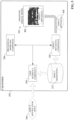
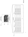
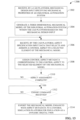
- FIG. 8 is an illustration of an example CAD file 802 that has been marked with aspect metadata 508.
- each element of a mechanical CAD drawing or model has an associated unique CAD entity identifier (ID) 804 with which that element's properties 808 (e.g., size, color, orientation, location, etc.) are associated.
- ID unique CAD entity identifier
- the element's type 806 e.g., sphere, cube, line, etc.
- entity IDs 804 are typically inherent to the existing CAD framework of a CAD platform, and the CAD file 802 for a given CAD model 402 includes the entity IDs 804 for the elements that make up the model 402.
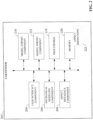
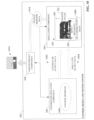
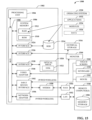
- Simulation component 306 can leverage the mechanical characteristics and associated aspect metadata 508 encoded in the enhanced digital model 502 to simulate operational aspects of the automation system to be monitored and regulated by the control program 1008.
- a user e.g., a controls engineer
- the developer can use the testing platform's configuration tools (e.g., a tag browser) to selectively map controller I/O defined by the control program 1008 to the I/O of the active control elements of the enhanced digital model 502 (that is, the control elements labeled with aspect metadata 508 designating these elements as having associated inputs and outputs available to be interfaced with an industrial controller's I/O, as documented by the master I/O list 702).
- the controls engineer may define the PLC tags and I/O addresses that drive a motor, actuator, or other component defined in the mechanical model 402, and selectively link the tags and associated I/O addresses to the I/O points defined for the modeled component.
- This I/O mapping between the control program 1008 and the digital model 502, which is part of the overall automation system design, can be stored in an appropriately formatted file (e.g., a spreadsheet or another type of file) as PLC connectivity data 1006 and integrated with the digital model 502.
- the digital model 502 maintains this aspect of the control design in addition to the mechanical design aspects.
- Control program 1008 can comprise any conceivable type of code used to process input signals read into a controller and to control output signals from the controller - including but not limited to ladder logic, sequential function charts, function block diagrams, or structured text - and is designed to regulate the automation system being modeled by digital model 502.
- simulation component 306 generates digital and analog I/O values representing, for example, sensor outputs, metering outputs, or other plant data analogous to the data expected to be generated by the physical system based on the static and dynamic characteristics of the physical system represented by the digital model 502.
- This simulated output data 1004 is provided to the emulation component 308 executing control program 1008, which receives this data 1004 as one or more virtual physical inputs.
- Control program 1008 processes these inputs according to user-defined algorithms and generates digital and/or analog controller output data 1002 based on the processing.
- This output data 1002 represents the physical outputs that would be generated by a controller executing control program 1008 and transmitted to the hardwired field devices comprising the automation system (e.g., PID loop control outputs, solenoid energizing outputs, motor control outputs, actuator control outputs, robot control outputs, etc.).
- the controller output data 1002 is provided to the appropriate input points of the digital model 502 in accordance with the user-defined I/O mapping.
- simulation component 306 In addition to generating simulated output data 1004, simulation component 306 also generates system response data 1018 based on analysis of the simulated data exchange and expected behaviors of the modeled automation system in response to the simulated controller output data 1002. The simulation component 306 estimates and simulates the virtual automation system's responses to the emulated controller outputs (and the timings of these outputs) based on the behavioral and physical properties and constraints defined by the aspect metadata 508 associated with respective control elements of the mechanical model 402.
- simulation component 306 can predict expected behaviors of the modeled industrial components - as well as behaviors of products being manufactured, processed, or handled by the components - in response to the controller output data 1002, and convey this predicted behavior as system response data 1018.
- Example behaviors represented by system response data 1018 can include, but are not limited to, movements and trajectories of industrial robots, movement of product through the simulated automation system (including speeds, accelerations, locations, lags, collisions, gripper failures, etc.), flow rates of fluids through the system, expected energy consumption by the system, an expected rate of degradation of mechanical components of the system (based in part on coefficient of friction information defined in the enhanced digital model 502), expected forces applied to respective components of the system during operation, or other such behaviors.
- the simulated interactions between these robots and the products can depend in part on the type of gripper aspect metadata 508 associated with the robot's end effector.
- suction gripper aspect metadata 508 may indicate to the simulation component 306 that products in proximity of the suction gripper can be assumed to have been gripped by the robot provided the suction effector is properly aligned above the part, and can subsequently be moved with the robot arm to simulate movement of the part by the robot until the part is released.
- mechanical gripper aspect metadata 508 may define more involved physics to be considered by the simulation component 306 before it can be assumed that the part has been securely gripped by the robot. This may include determining whether the two arms of the gripper are touching respective sides of the product, and at the proper angles or orientations, when the effector is in the gripped position before allowing the product to move in tandem with the robot.
- the simulation component 306 can assess these factors during the simulation to determine whether the product has been properly gripped, or alternatively whether a mis-grip is likely to occur due to misalignment. Instructions regarding how to properly assess this gripping behavior can be provided by the mechanical gripper aspect metadata 508 assigned to the robot.
- one or more components of the mechanical model 402 can be labeled with aspect metadata 508 designating those components as load sources.
- the simulation component 306 can recognize these components of the model as load sources that introduce product (e.g., manufactured parts, boxes, bottles, fluid material, etc.) into the automation system under test, and animate these components to simulate the release of product in accordance with the metadata.
- product e.g., manufactured parts, boxes, bottles, fluid material, etc.
- Default and user-defined metadata parameters assigned to these components can define a frequency at which the product is released, a type of product (e.g., discrete solid items or liquid material), a shape of the product (e.g., boxes having specified dimensions, spherical objects, items having random amorphous shapes due to the flexible material of which the items are made, etc.), a speed at which the product traverses the system, etc. Movement of these products through the simulated automation system may also be a function of the conveyor aspect metadata associated with the conveyor representations across which the product moves (e.g., the speed of the conveyor, the material of the belt used to convey the product, etc.).
- the simulation component 306 can also simulate predicted collisions between items of products, or between products and machinery (e.g., collisions with a pusher arm or robot arm due to a mis-timed control sequence). Repercussions of these collisions can be predicted and simulated based on physics rules and geometries modeled in part by the aspect metadata 508. Simulation component 306 can also leverage physics rules defined by the aspect metadata 508 to determine whether a mechanical gripper has properly gripped an item of product, or is likely to drop some or all items of product due to improper gripping.
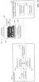
- a user interface component 304 associated with the testing system 302 can generate a visualization 1014 that renders results of the simulation on a client device.
- Visualization 1014 can render a graphical representation of the automation system based on the enhanced digital model 502, and animate this graphical representation based on the system response data 1018 and/or other calculated statistics relating to the simulation session, yielding a three-dimensional visual presentation of the automation system in operation.
- Some of the simulation data can also be rendered as alphanumeric overlays on visualization 1014. This simulation technique can be used to test and debug control programs without putting field equipment and machinery at risk, to test modifications to machine operations and estimate how such modifications affect certain key performance indicators or financial metrics, or to perform other types of analytics.
- users can control a speed of the simulation at a high degree of granularity. For example, a user may select to execute the simulation in real-time, such the simulation depicts operation of the automation system as it would transpire in real-time. Alternatively, the user may selectively choose to execute some or all phases of a simulated control sequence or process faster than real-time, in accordance with a time base specified by the user. This causes the simulation and its associated analysis to transpire within a compressed time frame.
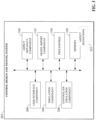
- control design and testing system 302 can allow the user to add to or modify aspects of the control design. This can include implementing and testing modifications to the control program 1008 based on observed results of the simulation. Some control design modifications submitted via the control design and testing system 302 may also be directed to the enhanced digital model 502.
- FIG. 11 is a diagram illustrating submission of control design updates to the control design and testing system 302. During the process of testing and debugging, a controls engineer may submit control design input 1106 via the testing platform's user interface component 304.
- design input submitted by mechanical and controls engineers via their respective development platforms is easily shared between the two engineering groups.
- This round-tripping of design information ensures that the mechanical and control design data remain synchronized, allowing continuous iteration of the machine design and the control system design that controls these mechanical aspects.
- This improved design workflow facilitates bidirectional synchronization between engineering work done on the simulation/control side and engineering work done on the CAD/mechanical side, with CAD being the focus of the two engineering threads.
- the illustrated embodiments herein can be also practiced in distributed computing environments where certain tasks are performed by remote processing devices that are linked through a communications network.
- program modules can be located in both local and remote memory storage devices.
Landscapes
- Engineering & Computer Science (AREA)
- Physics & Mathematics (AREA)
- Geometry (AREA)
- General Physics & Mathematics (AREA)
- Theoretical Computer Science (AREA)
- General Engineering & Computer Science (AREA)
- Computer Hardware Design (AREA)
- Evolutionary Computation (AREA)
- Computational Mathematics (AREA)
- Pure & Applied Mathematics (AREA)
- Mathematical Optimization (AREA)
- Mathematical Analysis (AREA)
- Human Computer Interaction (AREA)
- Architecture (AREA)
- Automation & Control Theory (AREA)
- Manufacturing & Machinery (AREA)
- Computer Networks & Wireless Communication (AREA)
- Quality & Reliability (AREA)
- Management, Administration, Business Operations System, And Electronic Commerce (AREA)
- Manipulator (AREA)
Claims (11)
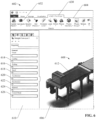
- System zum Entwickeln von Automatisierungssystemmodellen, umfassend:einen Speicher (1506), der ausführbare Komponenten speichert;einen Prozessor (1504), der betriebsfähig mit dem Speicher verbunden ist, der die ausführbaren Komponenten ausführt, wobei die ausführbaren Komponenten umfassen:eine Benutzerschnittstellenkomponente (204), die dazu konfiguriert ist, Eingabedaten für die mechanische Konstruktion zu empfangen; undeine mechanische Modellierungskomponente (206), die dazu konfiguriert ist, ein dreidimensionales, 3D, mechanisches Modell eines industriellen Automatisierungssystems auf der Grundlage der Eingabedaten für die mechanische Konstruktion zu erzeugen,wobeidie Benutzerschnittstellenkomponente des Weiteren dazu konfiguriert ist, Aspektspezifikations-Eingabedaten (504) zu empfangen, die ausgewählte Elemente des mechanischen 3D-Modells als spezifizierte Aspekte des industriellen Automatisierungssystems kennzeichnen, und die mechanischen Konstruktions-Eingabedaten und die Aspektspezifikations-Eingabedaten über eine Interaktion mit einer grafischen Schnittstellenanzeige zu empfangen, die von der Benutzerschnittstellenkomponente wiedergegeben wird,die ausführbaren Komponenten des Weiteren eine Aspekt-Metadatenkomponente umfassen, die dazu konfiguriert ist, den ausgewählten Elementen in Übereinstimmung mit den Aspekt-Eingabedaten Aspekt-Metadaten (508) zuzuweisen, wobei die Aspekt-Metadaten Simulationsverhaltensweisen der ausgewählten Elemente definieren, um einen digitalen Zwilling des industriellen Automatisierungssystems zu erhalten, der zur Simulation innerhalb einer Simulationsplattform in Übereinstimmung mit den Simulationsverhaltensweisen fähig ist,die Aspekt-Metadatenkomponente dazu konfiguriert ist, die Aspekt-Metadaten für die ausgewählten Elemente zu computergestützten Konstruktions- (CAD) Identifikatoren zuzuordnen, die jeweils den ausgewählten Elementen des mechanischen Modells entsprechen,eine CAD-Datei (802) für das Modell CAD-Identifikatoren für die Elemente enthält, aus denen das Modell besteht,die Aspekt-Metadaten für die ausgewählten Elemente der CAD-Datei in Verbindung mit den jeweiligen CAD-Identifikatoren der ausgewählten Elemente hinzugefügt werden,die grafische Schnittstellenanzeige eine Symbolleiste umfasst, die einen Satz von Aspekten wiedergibt, die zur Auswahl und Zuweisung zu den ausgewählten Elementen verfügbar sind, unddie Aspektspezifikations-Eingabedaten einen Aspekt aus dem Satz von Aspekten auswählen und ein Element der ausgewählten Elemente angeben, dem der Aspekt zugewiesen werden soll.
- Verfahren nach Anspruch 1, wobei mindestens eines aus Folgendem gilt:die verfügbaren Aspekte umfassen mindestens eines aus einem Gleitgelenk, einem Drehgelenk, einem Roboterarmgelenk, einem Scharnier, einem Förderer, einem Sauggreifer, einem mechanischen Greifer, einem Sensor, einem pneumatischen Aktuator, einem hydraulischen Aktuator, einem Schubarm, einem Stopper oder einer Rolle;die Aspekt-Metadatenkomponente ist dazu konfiguriert, als Reaktion auf den Empfang der Aspektspezifikations-Eingabedaten, die den Aspekt dem Element zuordnen, die Aspekt-Metadaten aus einer Aspekt-Metadatendefinition, die dem Aspekt entspricht, abzurufen und die Aspekt-Metadaten dem Element zuzuordnen; unddie Aspekt-Metadaten definieren eine oder mehrere Simulationseigenschaften, die dem Aspekt entsprechen, und die einen oder mehreren Simulationseigenschaften umfassen mindestens eine aus einer physikalischen Eigenschaft, einer kinematischen Eigenschaft, einer Bewegungsbeschränkung, einer Bewegungsreichweite, einer physikalischen Geometrie, einer Geschwindigkeit, einer Beschleunigung, einer Verzögerung, einem Reibungskoeffizienten, einer Trägheit, einem Material, einem Übersetzungsverhältnis, einem Zahnraddurchmesser, einer Bewegungsachse, einer Startposition oder einer Endposition.
- System nach einem der Ansprüche 1 bis 2, wobeidie Aspektspezifikations-Eingabedaten mindestens eines der ausgewählten Elemente als Lastquelle bezeichnen, die das Produkt in das Automatisierungssystem einführt, unddie Aspekt-Metadaten für die Lastquelle bewirken, dass die Simulationsplattform die Freigabe des Produkts an das Automatisierungssystem durch das eine der ausgewählten Elemente während der Simulation innerhalb der Simulationsplattform simuliert.
- System nach einem der Ansprüche 1 bis 3, des Weiteren umfassend eine Exportkomponente, die dazu konfiguriert ist, als Reaktion auf den Empfang einer Exportanweisung über die Benutzerschnittstellenkomponente den digitalen Zwilling zur Simulationsplattform zu exportieren.
- System nach Anspruch 4, für welches mindestens eines aus Folgendem gilt: wobeidie Aspekt-Metadatenkomponente des Weiteren dazu konfiguriert ist, als Reaktion auf das Bestimmen, dass die Aspekt-Metadaten für eines oder mehrere der ausgewählten Elemente einen Steuerungseingang oder einen Steuerungsausgang definieren, der dem Element zugeordnet ist, den Steuerungseingang oder den Steuerungsausgang zu einer Master-E/A-Liste für das Automatisierungssystem hinzuzufügen, unddie Exportkomponente des Weiteren dazu konfiguriert ist, die Master-E/A-Liste mit dem digitalen Zwilling an die Simulationsplattform zu exportieren; unddas System des Weiteren eine Importkomponente umfasst, die dazu konfiguriert ist, als Reaktion auf den Empfang eines Importbefehls über die Benutzerschnittstellenkomponente eine aktualisierte Version des digitalen Zwillings aus der Simulationsplattform zu importieren, wobei die aktualisierte Version des digitalen Zwillings eine Modifikation umfasst, die in der Simulationsplattform auf mindestens eines aus dem mechanischen Modell, den Aspekt-Metadaten oder den industriellen Steuerungsverbindungsinformationen angewendet wird.
- System nach Anspruch 1 oder 2, wobei die Symbolleiste und die Aspekt-Metadatenkomponenten installierbare Add-Ons zu einem CAD-System sind, das die Benutzerschnittstellen-Komponente und die mechanische Modellierungskomponente umfasst.
- Computerimplementiertes Verfahren zur Erstellung eines Simulationsmodells eines industriellen Automatisierungssystems, umfassend.Empfangen (1302), durch ein computergestütztes Konstruktionssystem (CAD), von Eingabedaten für die mechanische Konstruktion;Erzeugen (1304), durch das CAD-System, eines dreidimensionalen, 3D, mechanischen Modells des industriellen Automatisierungssystems auf der Grundlage der Eingabedaten für die mechanische Konstruktion;Empfangen (1306), durch das CAD-System, von Aspektspezifikations-Eingabedaten die ausgewählte Komponenten des mechanischen 3D-Modells als spezifizierte Aspekte des industriellen Automatisierungssystems kennzeichnen;Zuweisen (1308), durch das CAD-System, von Aspekt-Metadaten zu den ausgewählten Komponenten basierend auf den Aspekt-Eingangsdaten, wobei die Aspekt-Metadaten Simulationsverhaltensweisen der ausgewählten Komponenten definieren; undZuordnen, durch das CAD-System, der Aspekt-Metadaten für die ausgewählten Komponenten zu CAD-Kennungen, die jeweils den ausgewählten Komponenten des mechanischen Modells entsprechen,wobei eine CAD-Datei (802) für das Modell CAD-Identifikatoren für die Komponenten enthält, aus denen das Modell besteht,wobei die Aspekt-Metadaten für die ausgewählten Komponenten der CAD-Datei in Verbindung mit den jeweiligen CAD-Identifikatoren der ausgewählten Komponenten hinzugefügt werden,wobei das Zuweisen der Aspekt-Metadaten das mechanische Modell in einen digitalen Zwilling des industriellen Automatisierungssystems umwandelt, der zur Simulation innerhalb einer Simulationsplattform in Übereinstimmung mit den Simulationsverhaltensweisen fähig ist,wobei die Eingabedaten zur mechanischen Konstruktion und die Aspektspezifikations-Eingabedaten durch Interaktion mit der grafischen Schnittstellenanzeige empfangen werden,wobei das Wiedergeben das Wiedergeben, auf der grafischen Schnittstellenanzeige, einer Symbolleiste umfasst, die einen Satz von Aspekten umfasst, die zur Auswahl und Zuweisung an die ausgewählten Komponenten verfügbar sind, undwobei die Aspektspezifikations-Eingabedaten einen Aspekt aus dem Satz von Aspekten auswählen und eine Komponente aus den ausgewählten Komponenten identifizieren, der der Aspekt zugewiesen werden soll.
- Verfahren nach Anspruch 7, für das mindestens eines aus Folgendem gilt:wobei das Zuweisen der Aspekt-Metadaten das Abrufen der Aspekt-Metadaten aus einer Aspekt-Metadaten-Definition, die dem Aspekt entspricht, und das Zuordnen der Aspekt-Metadaten zu der Komponente umfasst; undwobei die Aspekt-Metadaten eine oder mehrere Simulationseigenschaften definieren, die dem Aspekt entsprechen, und die einen oder mehreren Simulationseigenschaften mindestens eine aus einer physikalischen Eigenschaft, einer kinematischen Eigenschaft, einer Bewegungsbeschränkung, einer Bewegungsreichweite, einer physikalischen Geometrie, einer Geschwindigkeit, einer Beschleunigung, einer Verzögerung, einem Reibungskoeffizienten, einer Trägheit, einem Material, einem Übersetzungsverhältnis, einem Zahnraddurchmesser, einer Bewegungsachse, einer Startposition oder einer Endposition umfassen.
- Verfahren nach Anspruch 7 oder 8, des Weiteren umfassend, als Reaktion auf den Empfang einer Exportanweisung über die Interaktion mit der grafischen Schnittstellenanzeige, das Exportieren, durch das CAD-System, des digitalen Zwillings an die Simulationsplattform.
- Verfahren nach Anspruch 9, für das mindestens eines aus Folgendem gilt:wobei das Verfahren des Weiteren als Reaktion auf das Bestimmen, dass die Aspekt-Metadaten für eine oder mehrere der ausgewählten Komponenten einen Steuerungseingang oder einen Steuerungsausgang definieren, der der Komponente zugeordnet ist, das Hinzufügen des Steuerungseingangs oder des Steuerungsausgangs zu einer Master-E/A-Liste für das Automatisierungssystem durch das CAD-System umfasst, undwobei das Exportieren das Exportieren der Master-E/A-Liste an die Simulationsplattform mit dem digitalen Zwilling umfasst; undwobei das Verfahren des Weiteren als Reaktion auf den Empfang eines Importbefehls durch Interaktion mit der grafischen Schnittstellenanzeige das Importieren, durch das CAD-System, einer aktualisierten Version des digitalen Zwillings von der Simulationsplattform umfasst, wobei die aktualisierte Version des digitalen Zwillings eine Modifikation umfasst, die in der Simulationsplattform auf mindestens eines aus dem mechanischen Modell, den Aspekt-Metadaten oder den industriellen Steuerungsverbindungsinformationen angewendet wird.
- Nichtflüchtiges computerlesbares Medium, auf dem Anweisungen gespeichert sind, die in Reaktion auf die Ausführung ein computergestütztes Konstruktionssystem (CAD), umfassend einen Prozessor, zum Durchführen von Abläufen veranlassen, wobei die Abläufe umfassen:Empfangen (1402) von Eingabedaten für die mechanische Konstruktion;Erzeugen (1404) eines dreidimensionalen, 3D, mechanischen Modells eines industriellen Automatisierungssystems auf der Grundlage der Eingabedaten für die mechanische Konstruktion;Empfangen (1406) von Aspektspezifikations-Eingabedaten, die spezifizierte Aspekte zu entsprechenden Elementen des mechanischen 3D-Modells zuordnen, wobei die Aspekte die Elemente als entsprechende Steuerelemente des Automatisierungssystems identifizieren;Zuweisen (1408) von Aspekt-Metadaten, die den spezifizierten Aspekten entsprechen, zu den Elementen in Übereinstimmung mit den Aspekt-Eingabedaten, wobei die Aspekt-Metadaten Simulationsverhaltensweisen der Elemente definieren;Zuordnen der Aspekt-Metadaten zu computergestützten Konstruktions- (CAD) Identifikatoren, die jeweils den ausgewählten Elementen des mechanischen Modells entsprechen,wobei eine CAD-Datei (802) für das Modell CAD-Identifikatoren für die Elemente enthält, aus denen das Modell besteht,wobei die Aspekt-Metadaten für die ausgewählten Elemente der CAD-Datei in Verbindung mit den jeweiligen CAD-Identifikatoren der ausgewählten Elemente hinzugefügt werden,wobei das Zuweisen der Aspekt-Metadaten bewirkt, dass das mechanische 3D-Modell in einen digitalen Zwilling umgewandelt wird, der in der Lage ist, das Verhalten des industriellen Automatisierungssystems innerhalb einer Simulationsplattform in Übereinstimmung mit den durch die Aspekt-Metadaten definierten Simulationsverhaltensweisen zu simulieren,wobei die Eingabedaten zur mechanischen Konstruktion und die Aspektspezifikations-Eingabedaten durch Interaktion mit einer grafischen Schnittstellenanzeige empfangen werden,wobei die grafische Schnittstellenanzeige eine Symbolleiste umfasst, die einen Satz von Aspekten umfasst, die zur Auswahl und Zuweisung an die ausgewählten Elemente verfügbar sind, undwobei das Empfangen der Aspektspezifikations-Eingabedaten das Auswählen eines Aspekts aus dem Satz von Aspekten und das Identifizieren eines Elements aus den ausgewählten Elementen umfasst, dem der Aspekt zugewiesen werden soll.
Applications Claiming Priority (1)
| Application Number | Priority Date | Filing Date | Title |
|---|---|---|---|
| US16/679,503 US12061845B2 (en) | 2019-11-11 | 2019-11-11 | Creation of a digital twin from a mechanical model |
Publications (2)
| Publication Number | Publication Date |
|---|---|
| EP3819733A1 EP3819733A1 (de) | 2021-05-12 |
| EP3819733B1 true EP3819733B1 (de) | 2025-03-05 |
Family
ID=73039810
Family Applications (1)
| Application Number | Title | Priority Date | Filing Date |
|---|---|---|---|
| EP20204067.1A Active EP3819733B1 (de) | 2019-11-11 | 2020-10-27 | Erzeugung eines digitalen zwillings aus einem mechanischen modell |
Country Status (3)
| Country | Link |
|---|---|
| US (1) | US12061845B2 (de) |
| EP (1) | EP3819733B1 (de) |
| CN (1) | CN112784328B (de) |
Families Citing this family (26)
| Publication number | Priority date | Publication date | Assignee | Title |
|---|---|---|---|---|
| US11520571B2 (en) * | 2019-11-12 | 2022-12-06 | Bright Machines, Inc. | Software defined manufacturing/assembly system |
| EP4102423A1 (de) * | 2021-06-07 | 2022-12-14 | Siemens Aktiengesellschaft | Automatische erzeugung der rechnung eines prozesses aus einem digitalen zwilling unter verwendung einer explorativen simulation |
| US12420408B1 (en) * | 2020-07-17 | 2025-09-23 | Bright Machines, Inc. | Human machine interface recipe building system for a robotic manufacturing system |
| CN116568465A (zh) | 2020-11-10 | 2023-08-08 | 光明机器公司 | 用于机器人单元的改进的自动校准的方法和系统 |
| EP4050538A1 (de) * | 2021-02-26 | 2022-08-31 | TGW Logistics Group GmbH | Verfahren und system zur bestimmung und/oder optimierung der betriebsbedingungen eines intralogistiksystems |
| US20220382922A1 (en) * | 2021-05-25 | 2022-12-01 | International Business Machines Corporation | Digital twin objects for product packaging compatibility |
| CN113343489B (zh) * | 2021-06-29 | 2024-04-09 | 重庆两江卫星移动通信有限公司 | 基于容器技术和数字孪生技术的卫星通信仿真方法及系统 |
| CA3226486A1 (en) | 2021-07-16 | 2023-01-19 | Bright Machines, Inc. | Method and apparatus for vision-based tool localization |
| CN117881370A (zh) * | 2021-08-30 | 2024-04-12 | 西门子工业软件有限公司 | 用于确定虚拟运动学装置中的关节的方法和系统 |
| JP7621919B2 (ja) * | 2021-09-22 | 2025-01-27 | 株式会社東芝 | 設計支援装置、設計支援システム、設計支援方法、プログラム、及び記憶媒体 |
| CN116341301A (zh) * | 2021-12-24 | 2023-06-27 | 上银科技股份有限公司 | 建立数字孪生模型的方法和系统 |
| US20230244826A1 (en) * | 2022-01-28 | 2023-08-03 | Hiwin Technologies Corp. | Method and System for Building Digital Twin Models |
| US20230303342A1 (en) * | 2022-03-25 | 2023-09-28 | Dexterity, Inc. | Robotic induction of heavy objects by pushing |
| WO2023198282A1 (en) | 2022-04-12 | 2023-10-19 | Telefonaktiebolaget Lm Ericsson (Publ) | Generative emulator for controllable physical systems |
| CN114692425B (zh) * | 2022-04-18 | 2023-08-01 | 武汉理工大学 | 数字孪生技术的焊接机器人仿真方法、系统、设备及介质 |
| CN114547826B (zh) * | 2022-04-25 | 2022-07-12 | 长江空间信息技术工程有限公司(武汉) | 基于数字孪生的工程变形监测网优化设计系统的运行方法 |
| WO2023214909A1 (en) | 2022-05-03 | 2023-11-09 | Telefonaktiebolaget Lm Ericsson (Publ) | Feature selective and generative digital twin emulator machine for device verification and anomaly checking |
| WO2023214910A1 (en) | 2022-05-03 | 2023-11-09 | Telefonaktiebolaget Lm Ericsson (Publ) | Machine for device verification and anomaly checking |
| CN114936455B (zh) * | 2022-05-18 | 2025-07-15 | 大连大学 | 一种无人机数字孪生体模型构建方法 |
| CN114978766B (zh) * | 2022-07-06 | 2024-01-05 | 深圳普汇智为科技有限公司 | 基于大数据的隐私安全保护方法、装置、设备及介质 |
| CN115348365B (zh) * | 2022-08-17 | 2023-07-21 | 北京瑞祺皓迪技术股份有限公司 | 一种基于数字孪生技术的运动过程展示方法及装置 |
| CN115984454A (zh) * | 2022-10-25 | 2023-04-18 | 北京商询科技有限公司 | 一种数字孪生场景构建方法、装置及电子设备 |
| CN115809489B (zh) * | 2022-11-15 | 2026-03-24 | 北京工业大学 | 一种基于ue4的数字孪生模型轻量优化方法及系统 |
| WO2025192646A1 (ja) * | 2024-03-14 | 2025-09-18 | 伊東電機株式会社 | 搬送システムのシミュレーション装置 |
| WO2025208240A1 (es) * | 2024-04-03 | 2025-10-09 | Rhenu Spa | Sistema y método para el monitoreo de la salud de activos físicos mediante gemelos digitales |
| CN119475791B (zh) * | 2024-11-12 | 2026-01-16 | 中国原子能科学研究院 | 吸取反应堆金属构件的切割物的模拟方法 |
Family Cites Families (58)
| Publication number | Priority date | Publication date | Assignee | Title |
|---|---|---|---|---|
| US5958012A (en) | 1996-07-18 | 1999-09-28 | Computer Associates International, Inc. | Network management system using virtual reality techniques to display and simulate navigation to network components |
| US8069021B2 (en) | 2007-09-28 | 2011-11-29 | Rockwell Automation Technologies, Inc. | Distributed simulation and synchronization |
| US20090089031A1 (en) | 2007-09-28 | 2009-04-02 | Rockwell Automation Technologies, Inc. | Integrated simulation of controllers and devices |
| CN104407518B (zh) | 2008-06-20 | 2017-05-31 | 因文西斯系统公司 | 对用于过程控制的实际和仿真设施进行交互的系统和方法 |
| CN101920233A (zh) | 2010-07-09 | 2010-12-22 | 广东工业大学 | 一种基于虚拟现实技术的喷涂工业机器人综合控制系统及控制方法 |
| CN103262080A (zh) | 2010-07-22 | 2013-08-21 | 卡格梅森机器人有限公司 | 一种无需编程介入的用于快速机器人仿真的创建可仿真三维机器人模型的非编程人员的方法 |
| US10037443B2 (en) | 2011-03-07 | 2018-07-31 | Rockwell Automation Technologies, Inc. | Industrial simulation using redirected I/O module configurations |
| US9052703B2 (en) | 2012-02-02 | 2015-06-09 | Emerson Process Management Power & Water Solutions, Inc. | Enhanced sequential method for solving pressure/flow network parameters in a real-time distributed industrial process simulation system |
| US10360316B2 (en) | 2012-12-21 | 2019-07-23 | Rockwell Automation Technologies, Inc. | Integration of simulation of a machine for industrial automation |
| US9703902B2 (en) | 2013-05-09 | 2017-07-11 | Rockwell Automation Technologies, Inc. | Using cloud-based data for industrial simulation |
| US9709978B2 (en) | 2013-05-09 | 2017-07-18 | Rockwell Automation Technologies, Inc. | Using cloud-based data for virtualization of an industrial automation environment with information overlays |
| US20140337277A1 (en) | 2013-05-09 | 2014-11-13 | Rockwell Automation Technologies, Inc. | Industrial device and system attestation in a cloud platform |
| US9989958B2 (en) | 2013-05-09 | 2018-06-05 | Rockwell Automation Technologies, Inc. | Using cloud-based data for virtualization of an industrial automation environment |
| US9715764B2 (en) | 2013-10-03 | 2017-07-25 | Honda Motor Co., Ltd. | System and method for dynamic in-vehicle virtual reality |
| US10755003B2 (en) | 2013-11-08 | 2020-08-25 | Rockwell Automation Technologies, Inc. | Time synchronization of signal transmission intervals for simulating a machine in industrial automation |
| US11972177B2 (en) | 2013-11-08 | 2024-04-30 | Rockwell Automation Technologies, Inc. | Interface for data exchange between industrial controllers and simulation applications for simulating a machine |
| US9530250B2 (en) | 2013-12-10 | 2016-12-27 | Dassault Systemes | Augmented reality updating of 3D CAD models |
| US20170124770A1 (en) | 2014-03-15 | 2017-05-04 | Nitin Vats | Self-demonstrating object features and/or operations in interactive 3d-model of real object for understanding object's functionality |
| US10095202B2 (en) | 2014-03-26 | 2018-10-09 | Rockwell Automation Technologies, Inc. | Multiple controllers configuration management interface for system connectivity |
| EP2952988B1 (de) | 2014-06-03 | 2020-07-29 | Siemens Aktiengesellschaft | Verfahren zur Berechnung einer optimierten Trajektorie |
| US11256224B2 (en) | 2014-10-01 | 2022-02-22 | Rockwell Automation Technologies, Inc. | Virtual design engineering |
| EP3002649B1 (de) | 2014-10-01 | 2018-09-26 | Rockwell Automation Technologies, Inc. | Industrielle simulation mit umgeleiteten e/a-modul-konfigurationen |
| CN107077339B (zh) | 2014-10-02 | 2021-09-14 | 西门子公司 | 利用紧密耦合逻辑和物理仿真的3d图形编辑器中的编程自动化 |
| US20160182309A1 (en) | 2014-12-22 | 2016-06-23 | Rockwell Automation Technologies, Inc. | Cloud-based emulation and modeling for automation systems |
| US10496061B2 (en) | 2015-03-16 | 2019-12-03 | Rockwell Automation Technologies, Inc. | Modeling of an industrial automation environment in the cloud |
| US11243505B2 (en) | 2015-03-16 | 2022-02-08 | Rockwell Automation Technologies, Inc. | Cloud-based analytics for industrial automation |
| US11513477B2 (en) | 2015-03-16 | 2022-11-29 | Rockwell Automation Technologies, Inc. | Cloud-based industrial controller |
| US11222551B2 (en) | 2015-07-23 | 2022-01-11 | Rockwell Automation Technologies, Inc. | Snapshot management architecture for process control operator training system lifecycle |
| FR3039643B1 (fr) | 2015-07-31 | 2018-07-13 | Thales | Interface homme-machine pour la gestion du vol d'un aeronef |
| DE112016003719T5 (de) | 2015-08-15 | 2018-05-09 | Google LLC (n.d.Ges.d. Staates Delaware) | System und Verfahren für Biomechanik-basierte Augensignale zur Interaktion mit realen und virtuellen Objekten |
| US10747915B2 (en) | 2015-08-18 | 2020-08-18 | Siemens Aktiengesellschaft | Programming automation sensor applications using simulation |
| US10551826B2 (en) | 2016-03-24 | 2020-02-04 | Andrei Popa-Simil | Method and system to increase operator awareness |
| US11080435B2 (en) | 2016-04-29 | 2021-08-03 | Accenture Global Solutions Limited | System architecture with visual modeling tool for designing and deploying complex models to distributed computing clusters |
| US20170323240A1 (en) | 2016-05-06 | 2017-11-09 | General Electric Company | Computing system to control the use of physical state attainment with inspection |
| US11366455B2 (en) | 2016-05-09 | 2022-06-21 | Strong Force Iot Portfolio 2016, Llc | Methods and systems for optimization of data collection and storage using 3rd party data from a data marketplace in an industrial internet of things environment |
| US20180052451A1 (en) | 2016-08-19 | 2018-02-22 | Rockwell Automation Technologies, Inc. | Remote industrial automation site operation in a cloud platform |
| US10388075B2 (en) | 2016-11-08 | 2019-08-20 | Rockwell Automation Technologies, Inc. | Virtual reality and augmented reality for industrial automation |
| US10735691B2 (en) | 2016-11-08 | 2020-08-04 | Rockwell Automation Technologies, Inc. | Virtual reality and augmented reality for industrial automation |
| US10740502B2 (en) | 2017-02-22 | 2020-08-11 | Middle Chart, LLC | Method and apparatus for position based query with augmented reality headgear |
| CN106774949A (zh) | 2017-03-09 | 2017-05-31 | 北京神州四达科技有限公司 | 协同仿真交互方法、装置和系统 |
| US10409950B2 (en) | 2017-03-10 | 2019-09-10 | General Electric Company | Systems and methods for utilizing a 3D CAD point-cloud to automatically create a fluid model |
| US10867085B2 (en) | 2017-03-10 | 2020-12-15 | General Electric Company | Systems and methods for overlaying and integrating computer aided design (CAD) drawings with fluid models |
| WO2018199948A1 (en) | 2017-04-27 | 2018-11-01 | Siemens Aktiengesellschaft | Authoring augmented reality experiences using augmented reality and virtual reality |
| US10908602B2 (en) | 2017-08-02 | 2021-02-02 | Strong Force Iot Portfolio 2016, Llc | Systems and methods for network-sensitive data collection |
| CA3072045A1 (en) | 2017-08-02 | 2019-02-07 | Strong Force Iot Portfolio 2016, Llc | Methods and systems for detection in an industrial internet of things data collection environment with large data sets |
| US11074827B2 (en) | 2017-08-25 | 2021-07-27 | Aurora Flight Sciences Corporation | Virtual reality system for aerial vehicle |
| EP3557453B1 (de) | 2017-08-29 | 2023-05-03 | Siemens Aktiengesellschaft | Verfahren und vorrichtung zur bestimmung einer datenleseperiode |
| US11435728B2 (en) | 2017-10-02 | 2022-09-06 | Fisher-Rosemount Systems, Inc. | I/O virtualization for commissioning |
| CN107832497B (zh) | 2017-10-17 | 2018-08-28 | 广东工业大学 | 一种智能车间快速定制设计方法及系统 |
| CN107577159A (zh) | 2017-10-31 | 2018-01-12 | 塔普翊海(上海)智能科技有限公司 | 扩增实境仿真系统 |
| US10410426B2 (en) | 2017-12-19 | 2019-09-10 | GM Global Technology Operations LLC | Augmented reality vehicle user interface |
| JP7146402B2 (ja) | 2018-01-18 | 2022-10-04 | キヤノン株式会社 | 情報処理装置、および情報処理方法 |
| FR3077900B1 (fr) | 2018-02-12 | 2020-01-17 | Thales | Vision peripherique dans une interface homme-machine |
| US10832548B2 (en) | 2018-05-02 | 2020-11-10 | Rockwell Automation Technologies, Inc. | Advanced industrial safety notification systems |
| US11528582B2 (en) | 2018-05-29 | 2022-12-13 | Apprentice FS, Inc. | Assisting execution of manual protocols at production equipment |
| US11144042B2 (en) | 2018-07-09 | 2021-10-12 | Rockwell Automation Technologies, Inc. | Industrial automation information contextualization method and system |
| US10596704B1 (en) | 2018-09-27 | 2020-03-24 | Rapyuta Robotics Co., Ltd | Generate, simulate, and execute a reusable robotics solution recipe to execute a robotic solution |
| US11392112B2 (en) | 2019-09-26 | 2022-07-19 | Rockwell Automation Technologies, Inc. | Virtual design environment |
-
2019
- 2019-11-11 US US16/679,503 patent/US12061845B2/en active Active
-
2020
- 2020-10-27 EP EP20204067.1A patent/EP3819733B1/de active Active
- 2020-11-10 CN CN202011245904.2A patent/CN112784328B/zh active Active
Also Published As
| Publication number | Publication date |
|---|---|
| US12061845B2 (en) | 2024-08-13 |
| EP3819733A1 (de) | 2021-05-12 |
| CN112784328B (zh) | 2024-04-26 |
| US20210141870A1 (en) | 2021-05-13 |
| CN112784328A (zh) | 2021-05-11 |
Similar Documents
| Publication | Publication Date | Title |
|---|---|---|
| EP3819733B1 (de) | Erzeugung eines digitalen zwillings aus einem mechanischen modell | |
| US11638994B2 (en) | Robotic digital twin control with industrial context simulation | |
| EP4002189A1 (de) | Emulation einer industriellen netzwerkkommunikation | |
| US11675936B2 (en) | Unifying multiple simulation models | |
| EP3865961B1 (de) | Test der erweiterten realität der mensch-maschine-schnittstelle | |
| US11947884B2 (en) | Industrial automation process simulation for fluid flow | |
| EP3971758A1 (de) | Emulation eines industriellen netzwerks | |
| EP3002646B1 (de) | Virtuelle designentwicklung | |
| EP3974928B1 (de) | Schaltplanmanager und emulator | |
| CN119739048A (zh) | 一种基于数字孪生的fsm仿真系统及其工作方法 | |
| Le et al. | Emulate3D: Design and Application for Education in the Engineering Maintenance |
Legal Events
| Date | Code | Title | Description |
|---|---|---|---|
| PUAI | Public reference made under article 153(3) epc to a published international application that has entered the european phase |
Free format text: ORIGINAL CODE: 0009012 |
|
| STAA | Information on the status of an ep patent application or granted ep patent |
Free format text: STATUS: THE APPLICATION HAS BEEN PUBLISHED |
|
| AK | Designated contracting states |
Kind code of ref document: A1 Designated state(s): AL AT BE BG CH CY CZ DE DK EE ES FI FR GB GR HR HU IE IS IT LI LT LU LV MC MK MT NL NO PL PT RO RS SE SI SK SM TR |
|
| STAA | Information on the status of an ep patent application or granted ep patent |
Free format text: STATUS: REQUEST FOR EXAMINATION WAS MADE |
|
| 17P | Request for examination filed |
Effective date: 20211102 |
|
| RBV | Designated contracting states (corrected) |
Designated state(s): AL AT BE BG CH CY CZ DE DK EE ES FI FR GB GR HR HU IE IS IT LI LT LU LV MC MK MT NL NO PL PT RO RS SE SI SK SM TR |
|
| STAA | Information on the status of an ep patent application or granted ep patent |
Free format text: STATUS: EXAMINATION IS IN PROGRESS |
|
| 17Q | First examination report despatched |
Effective date: 20231212 |
|
| GRAP | Despatch of communication of intention to grant a patent |
Free format text: ORIGINAL CODE: EPIDOSNIGR1 |
|
| STAA | Information on the status of an ep patent application or granted ep patent |
Free format text: STATUS: GRANT OF PATENT IS INTENDED |
|
| RIC1 | Information provided on ipc code assigned before grant |
Ipc: G06F 30/17 20200101ALI20240927BHEP Ipc: G06F 30/12 20200101ALI20240927BHEP Ipc: G06F 30/10 20200101ALI20240927BHEP Ipc: G06F 30/18 20200101ALI20240927BHEP Ipc: G06F 30/20 20200101ALI20240927BHEP Ipc: G05B 19/418 20060101AFI20240927BHEP |
|
| INTG | Intention to grant announced |
Effective date: 20241010 |
|
| GRAS | Grant fee paid |
Free format text: ORIGINAL CODE: EPIDOSNIGR3 |
|
| GRAA | (expected) grant |
Free format text: ORIGINAL CODE: 0009210 |
|
| STAA | Information on the status of an ep patent application or granted ep patent |
Free format text: STATUS: THE PATENT HAS BEEN GRANTED |
|
| AK | Designated contracting states |
Kind code of ref document: B1 Designated state(s): AL AT BE BG CH CY CZ DE DK EE ES FI FR GB GR HR HU IE IS IT LI LT LU LV MC MK MT NL NO PL PT RO RS SE SI SK SM TR |
|
| REG | Reference to a national code |
Ref country code: GB Ref legal event code: FG4D |
|
| REG | Reference to a national code |
Ref country code: CH Ref legal event code: EP |
|
| REG | Reference to a national code |
Ref country code: IE Ref legal event code: FG4D |
|
| REG | Reference to a national code |
Ref country code: DE Ref legal event code: R096 Ref document number: 602020047110 Country of ref document: DE |
|
| PG25 | Lapsed in a contracting state [announced via postgrant information from national office to epo] |
Ref country code: RS Free format text: LAPSE BECAUSE OF FAILURE TO SUBMIT A TRANSLATION OF THE DESCRIPTION OR TO PAY THE FEE WITHIN THE PRESCRIBED TIME-LIMIT Effective date: 20250605 |
|
| PG25 | Lapsed in a contracting state [announced via postgrant information from national office to epo] |
Ref country code: FI Free format text: LAPSE BECAUSE OF FAILURE TO SUBMIT A TRANSLATION OF THE DESCRIPTION OR TO PAY THE FEE WITHIN THE PRESCRIBED TIME-LIMIT Effective date: 20250305 |
|
| REG | Reference to a national code |
Ref country code: NL Ref legal event code: MP Effective date: 20250305 |
|
| PG25 | Lapsed in a contracting state [announced via postgrant information from national office to epo] |
Ref country code: ES Free format text: LAPSE BECAUSE OF FAILURE TO SUBMIT A TRANSLATION OF THE DESCRIPTION OR TO PAY THE FEE WITHIN THE PRESCRIBED TIME-LIMIT Effective date: 20250305 |
|
| REG | Reference to a national code |
Ref country code: LT Ref legal event code: MG9D |
|
| PG25 | Lapsed in a contracting state [announced via postgrant information from national office to epo] |
Ref country code: NO Free format text: LAPSE BECAUSE OF FAILURE TO SUBMIT A TRANSLATION OF THE DESCRIPTION OR TO PAY THE FEE WITHIN THE PRESCRIBED TIME-LIMIT Effective date: 20250605 |
|
| PG25 | Lapsed in a contracting state [announced via postgrant information from national office to epo] |
Ref country code: HR Free format text: LAPSE BECAUSE OF FAILURE TO SUBMIT A TRANSLATION OF THE DESCRIPTION OR TO PAY THE FEE WITHIN THE PRESCRIBED TIME-LIMIT Effective date: 20250305 |
|
| PG25 | Lapsed in a contracting state [announced via postgrant information from national office to epo] |
Ref country code: LV Free format text: LAPSE BECAUSE OF FAILURE TO SUBMIT A TRANSLATION OF THE DESCRIPTION OR TO PAY THE FEE WITHIN THE PRESCRIBED TIME-LIMIT Effective date: 20250305 |
|
| PG25 | Lapsed in a contracting state [announced via postgrant information from national office to epo] |
Ref country code: GR Free format text: LAPSE BECAUSE OF FAILURE TO SUBMIT A TRANSLATION OF THE DESCRIPTION OR TO PAY THE FEE WITHIN THE PRESCRIBED TIME-LIMIT Effective date: 20250606 Ref country code: BG Free format text: LAPSE BECAUSE OF FAILURE TO SUBMIT A TRANSLATION OF THE DESCRIPTION OR TO PAY THE FEE WITHIN THE PRESCRIBED TIME-LIMIT Effective date: 20250305 |
|
| REG | Reference to a national code |
Ref country code: AT Ref legal event code: MK05 Ref document number: 1773465 Country of ref document: AT Kind code of ref document: T Effective date: 20250305 |
|
| PG25 | Lapsed in a contracting state [announced via postgrant information from national office to epo] |
Ref country code: NL Free format text: LAPSE BECAUSE OF FAILURE TO SUBMIT A TRANSLATION OF THE DESCRIPTION OR TO PAY THE FEE WITHIN THE PRESCRIBED TIME-LIMIT Effective date: 20250305 |
|
| PG25 | Lapsed in a contracting state [announced via postgrant information from national office to epo] |
Ref country code: SE Free format text: LAPSE BECAUSE OF FAILURE TO SUBMIT A TRANSLATION OF THE DESCRIPTION OR TO PAY THE FEE WITHIN THE PRESCRIBED TIME-LIMIT Effective date: 20250305 |
|
| PG25 | Lapsed in a contracting state [announced via postgrant information from national office to epo] |
Ref country code: SM Free format text: LAPSE BECAUSE OF FAILURE TO SUBMIT A TRANSLATION OF THE DESCRIPTION OR TO PAY THE FEE WITHIN THE PRESCRIBED TIME-LIMIT Effective date: 20250305 |
|
| PG25 | Lapsed in a contracting state [announced via postgrant information from national office to epo] |
Ref country code: PT Free format text: LAPSE BECAUSE OF FAILURE TO SUBMIT A TRANSLATION OF THE DESCRIPTION OR TO PAY THE FEE WITHIN THE PRESCRIBED TIME-LIMIT Effective date: 20250707 |
|
| PG25 | Lapsed in a contracting state [announced via postgrant information from national office to epo] |
Ref country code: PL Free format text: LAPSE BECAUSE OF FAILURE TO SUBMIT A TRANSLATION OF THE DESCRIPTION OR TO PAY THE FEE WITHIN THE PRESCRIBED TIME-LIMIT Effective date: 20250305 Ref country code: IT Free format text: LAPSE BECAUSE OF FAILURE TO SUBMIT A TRANSLATION OF THE DESCRIPTION OR TO PAY THE FEE WITHIN THE PRESCRIBED TIME-LIMIT Effective date: 20250305 |
|
| PGFP | Annual fee paid to national office [announced via postgrant information from national office to epo] |
Ref country code: GB Payment date: 20250923 Year of fee payment: 6 |
|
| PG25 | Lapsed in a contracting state [announced via postgrant information from national office to epo] |
Ref country code: AT Free format text: LAPSE BECAUSE OF FAILURE TO SUBMIT A TRANSLATION OF THE DESCRIPTION OR TO PAY THE FEE WITHIN THE PRESCRIBED TIME-LIMIT Effective date: 20250305 |
|
| PGFP | Annual fee paid to national office [announced via postgrant information from national office to epo] |
Ref country code: FR Payment date: 20250924 Year of fee payment: 6 |
|
| PG25 | Lapsed in a contracting state [announced via postgrant information from national office to epo] |
Ref country code: CZ Free format text: LAPSE BECAUSE OF FAILURE TO SUBMIT A TRANSLATION OF THE DESCRIPTION OR TO PAY THE FEE WITHIN THE PRESCRIBED TIME-LIMIT Effective date: 20250305 Ref country code: EE Free format text: LAPSE BECAUSE OF FAILURE TO SUBMIT A TRANSLATION OF THE DESCRIPTION OR TO PAY THE FEE WITHIN THE PRESCRIBED TIME-LIMIT Effective date: 20250305 |
|
| PG25 | Lapsed in a contracting state [announced via postgrant information from national office to epo] |
Ref country code: RO Free format text: LAPSE BECAUSE OF FAILURE TO SUBMIT A TRANSLATION OF THE DESCRIPTION OR TO PAY THE FEE WITHIN THE PRESCRIBED TIME-LIMIT Effective date: 20250305 |
|
| PG25 | Lapsed in a contracting state [announced via postgrant information from national office to epo] |
Ref country code: SK Free format text: LAPSE BECAUSE OF FAILURE TO SUBMIT A TRANSLATION OF THE DESCRIPTION OR TO PAY THE FEE WITHIN THE PRESCRIBED TIME-LIMIT Effective date: 20250305 |
|
| PG25 | Lapsed in a contracting state [announced via postgrant information from national office to epo] |
Ref country code: IS Free format text: LAPSE BECAUSE OF FAILURE TO SUBMIT A TRANSLATION OF THE DESCRIPTION OR TO PAY THE FEE WITHIN THE PRESCRIBED TIME-LIMIT Effective date: 20250705 |
|
| REG | Reference to a national code |
Ref country code: DE Ref legal event code: R097 Ref document number: 602020047110 Country of ref document: DE |
|
| PGFP | Annual fee paid to national office [announced via postgrant information from national office to epo] |
Ref country code: DE Payment date: 20250923 Year of fee payment: 6 |
|
| PLBE | No opposition filed within time limit |
Free format text: ORIGINAL CODE: 0009261 |
|
| STAA | Information on the status of an ep patent application or granted ep patent |
Free format text: STATUS: NO OPPOSITION FILED WITHIN TIME LIMIT |
|
| PG25 | Lapsed in a contracting state [announced via postgrant information from national office to epo] |
Ref country code: DK Free format text: LAPSE BECAUSE OF FAILURE TO SUBMIT A TRANSLATION OF THE DESCRIPTION OR TO PAY THE FEE WITHIN THE PRESCRIBED TIME-LIMIT Effective date: 20250305 |
|
| REG | Reference to a national code |
Ref country code: CH Ref legal event code: L10 Free format text: ST27 STATUS EVENT CODE: U-0-0-L10-L00 (AS PROVIDED BY THE NATIONAL OFFICE) Effective date: 20260114 |
|
| 26N | No opposition filed |
Effective date: 20251208 |