EP3819683A1 - Design method for composite membrane and composite membrane - Google Patents
Design method for composite membrane and composite membrane Download PDFInfo
- Publication number
- EP3819683A1 EP3819683A1 EP19831124.3A EP19831124A EP3819683A1 EP 3819683 A1 EP3819683 A1 EP 3819683A1 EP 19831124 A EP19831124 A EP 19831124A EP 3819683 A1 EP3819683 A1 EP 3819683A1
- Authority
- EP
- European Patent Office
- Prior art keywords
- dispersive
- base plate
- areas
- area
- composite membrane
- Prior art date
- Legal status (The legal status is an assumption and is not a legal conclusion. Google has not performed a legal analysis and makes no representation as to the accuracy of the status listed.)
- Pending
Links
Images


Classifications
-
- G—PHYSICS
- G02—OPTICS
- G02B—OPTICAL ELEMENTS, SYSTEMS OR APPARATUS
- G02B5/00—Optical elements other than lenses
- G02B5/04—Prisms
- G02B5/045—Prism arrays
-
- G—PHYSICS
- G01—MEASURING; TESTING
- G01J—MEASUREMENT OF INTENSITY, VELOCITY, SPECTRAL CONTENT, POLARISATION, PHASE OR PULSE CHARACTERISTICS OF INFRARED, VISIBLE OR ULTRAVIOLET LIGHT; COLORIMETRY; RADIATION PYROMETRY
- G01J1/00—Photometry, e.g. photographic exposure meter
- G01J1/10—Photometry, e.g. photographic exposure meter by comparison with reference light or electric value provisionally void
-
- G—PHYSICS
- G02—OPTICS
- G02B—OPTICAL ELEMENTS, SYSTEMS OR APPARATUS
- G02B27/00—Optical systems or apparatus not provided for by any of the groups G02B1/00 - G02B26/00, G02B30/00
- G02B27/0012—Optical design, e.g. procedures, algorithms, optimisation routines
-
- G—PHYSICS
- G02—OPTICS
- G02B—OPTICAL ELEMENTS, SYSTEMS OR APPARATUS
- G02B5/00—Optical elements other than lenses
- G02B5/02—Diffusing elements; Afocal elements
- G02B5/0205—Diffusing elements; Afocal elements characterised by the diffusing properties
- G02B5/021—Diffusing elements; Afocal elements characterised by the diffusing properties the diffusion taking place at the element's surface, e.g. by means of surface roughening or microprismatic structures
- G02B5/0226—Diffusing elements; Afocal elements characterised by the diffusing properties the diffusion taking place at the element's surface, e.g. by means of surface roughening or microprismatic structures having particles on the surface
-
- G—PHYSICS
- G02—OPTICS
- G02B—OPTICAL ELEMENTS, SYSTEMS OR APPARATUS
- G02B5/00—Optical elements other than lenses
- G02B5/02—Diffusing elements; Afocal elements
- G02B5/0205—Diffusing elements; Afocal elements characterised by the diffusing properties
- G02B5/021—Diffusing elements; Afocal elements characterised by the diffusing properties the diffusion taking place at the element's surface, e.g. by means of surface roughening or microprismatic structures
- G02B5/0231—Diffusing elements; Afocal elements characterised by the diffusing properties the diffusion taking place at the element's surface, e.g. by means of surface roughening or microprismatic structures the surface having microprismatic or micropyramidal shape
-
- G—PHYSICS
- G01—MEASURING; TESTING
- G01J—MEASUREMENT OF INTENSITY, VELOCITY, SPECTRAL CONTENT, POLARISATION, PHASE OR PULSE CHARACTERISTICS OF INFRARED, VISIBLE OR ULTRAVIOLET LIGHT; COLORIMETRY; RADIATION PYROMETRY
- G01J3/00—Spectrometry; Spectrophotometry; Monochromators; Measuring colours
- G01J3/46—Measurement of colour; Colour measuring devices, e.g. colorimeters
- G01J3/50—Measurement of colour; Colour measuring devices, e.g. colorimeters using electric radiation detectors
- G01J3/506—Measurement of colour; Colour measuring devices, e.g. colorimeters using electric radiation detectors measuring the colour produced by screens, monitors, displays or CRTs
Definitions
- the present disclosure relates to the technical field of backlight modules, and more particularly, to a design method for a composite membrane and the composite membrane.
- a backlight module having a same size Due to a limitation of lens technology and a trend requirement of cost reduction, for a backlight module having a same size, a number of a plurality of LED light sources used is becoming less and less, while a space between the LED light sources increases accordingly, which makes both a direct-lit backlight module and a side-lit backlight module have a problem of an uneven visual effect.
- a poor light mixing may appear in the visual effect, which is shown as a light spot phenomenon including a plurality of bright spots or a plurality of dark spots on a lamp; for the side-lit backlight module, it is shown as a lamp bead shadow problem including a plurality of bright lights and a plurality of dark lights alternating in the visual effect.
- a technical problem to be solved by the present disclosure is that, in view of the defects described above in the prior art, providing a design method for a composite membrane and the composite membrane, aimed at improving the phenomenon of uneven visual effect of the backlight module.
- a design method for a composite membrane comprising a plurality of steps:
- the design method for the composite membrane wherein the step of establishing the rectangular test area corresponding to each of the LED light sources on the test board, and detecting the brightness uniformity on each of the rectangular test areas, comprises specifically:
- test point in middle of the nine test points locates at a center of the rectangular test area, a space between every two adjacent rows of the LED light sources is equal, and a space between every two adjacent columns of the LED light sources is equal.
- the design method for the composite membrane wherein the step of arranging the base plate on the light-emitting surface of the plurality of LED light sources, and arranging the plurality of dispersive prism areas and the plurality of diffusion plates on the light-emitting surface of the base plate respectively, while making the dispersive prism areas correspond to the lamp bead shadow areas, and the diffusion plates correspond to the non-lamp bead shadow areas, comprises specifically:
- the design method for the composite membrane wherein the dispersive prism area comprises a plurality of first dispersive prisms and a plurality of second dispersive prisms, a height of the second dispersive prisms is smaller than a height of the first dispersive prisms, the first dispersive prisms and the second dispersive prisms are arranged alternately.
- a composite membrane wherein comprising a base plate, the base plate is applied to corresponding to a light source, a light-emitting surface of the base plate has a plurality of dispersive prism areas and a plurality of diffusion plates arranged, while the dispersive prism areas are corresponding to the lamp bead shadow areas, and the diffusion plates are corresponding to the non-lamp bead shadow areas.
- the composite membrane, wherein the base plate is a PET base plate.
- the composite membrane wherein the diffusion plate comprises a coating layer arranged on the light-emitting surface of the base plate, and a plurality of diffusion particles arranged on a surface of the coating layer against the base plate.
- the composite membrane, wherein the coating layer is a UV photosensitive adhesive coating layer is a UV photosensitive adhesive coating layer.
- the composite membrane wherein the dispersive prism area comprises a plurality of dispersive prisms arranged in a matrix, a first quadrangular surface of the dispersive prism attaches to the base plate, a surface against the base plate of a second quadrangular surface and a third quadrangular surface of the dispersive prism has a plurality of first diffusion particles arranged.
- the composite membrane wherein the first diffusion particles are hemispherical shaped, while the second quadrangular surface and the third quadrangular surface of the dispersive prism are in contact with a plane of the first diffusion particle, correspondingly and respectively.
- the composite membrane wherein the dispersive prism area comprises a plurality of first dispersive prisms and a plurality of second dispersive prisms, a height of the second dispersive prism is smaller than a height of the first dispersive prism, while the first dispersive prism and the second dispersive prism are arranged alternately.
- the composite membrane wherein a distance from a top of the first dispersive prism and a top of the second dispersive prism is 30 ⁇ m - 50 ⁇ m.
- the present disclosure arranges a plurality of dispersive prism areas and a plurality of diffusion plates on the light-emitting surface of the base plate, while the dispersive prism areas are corresponding to the lamp bead shadow areas, and the diffusion plates are corresponding to the non-lamp bead shadow areas.
- FIG.s 1-11 wherein a plurality of arrows in FIG. 2 and FIG. 5 illustrates a light emitting direction.
- the present disclosure provides a design method for a composite membrane, shown as FIG. 1 , comprising a plurality of steps below:
- the composite membrane is suitable for both a direct-lit backlight module and a side-lit backlight module; for the direct-lit backlight module, the test board 1 in the present disclosure is a diffusion plate; for the side-lit backlight module, the test board 1 in the present disclosure is a light guide plate.
- the plurality of LED light sources 10 are arranged in a matrix on a back plate, and a total rectangular area covered by the plurality of LED light sources 10 on the back plate has an area smaller than an area of a surface of the test board 1 facing toward the LED light source 10, and the area of the surface of the test board 1 facing toward the LED light source 10 increases following a distance increase between the test board 1 and the LED light source 10, that is, the smaller a distance between the test board 1 and the LED light source 10 is, the smaller an area of the test board 1 needed is; the bigger the distance between the test board 1 and the LED light source 10 is, the bigger the area of the test board 1 needed is.
- the step S200 comprises specifically:
- the rectangular test area faces to the LED light source 10 directly, and the rectangular test area covers completely an area where the LED light source 10 generates a light shadow on the test board 1; preferably, a center point of the rectangular test area corresponds to a center point of the LED light source 10, a length of the rectangular test area is L, and a width thereof is H.
- FIG. 8 selecting nine test points in the rectangular test area: L1, L2, L3, L4, L5, L6, L7, L8, and L9, while the nine test points are arranged in three rows and three columns, a space between every two adjacent rows is equal, and a space between every two adjacent columns is equal. That is, a distance between L1 and L2 equals to a distance between L2 and L3, a distance between L1 and L4 equals to a distance between L4 and L7.
- a test point locates in middle of the nine test points is L5, a center of the LED light source 10 corresponding to the rectangular test area is against the L5, and L5 also locates at a center of the rectangular test area.
- the rectangular test area comprises a first side a1, a second side a2, a third side a3, and a fourth side a4 connecting end to end in a sequence, wherein a length of the first side a1 is L, a length of the second side a2 is H.
- a row that L1, L2, L3 locates is parallel to the first side a1
- a column that L1, L4, L7 locates is parallel to the second side a2. While a distance between L1 and the first side a1 equals to a distance between L7 and the third side a3, and a distance between L1 and the fourth side a4 equals to a distance between L3 and the second side a2.
- the distance between L1 and the first side a1 is H/10
- a distance between L1 and L2 is 0.4L
- the distance between L1 and the fourth side a4 is L/10
- both a distance between L2 and the second side a2 and a distance between L2 and the fourth side a4 is L/2
- both a distance between L5 and the first side a1 and a distance between L5 and the third side a3 is H/2
- detecting a brightness at each of the test points according to a position of the nine test points, wherein, a brightness of the test point L1 is A1, a brightness of the test point L2 is A2, a brightness of the test point L3 is A3, a brightness of the test point L4 is A4, a brightness of the test point L5 is A5, a brightness of the test point L6 is A6, a brightness of the test point L7 is A7, a brightness of the test point L8 is A8.
- the preset value is 80 %, when the brightness uniformity is less than 80%, the rectangular test area corresponding to the brightness uniformity is the lamp bead shadow area 2, a light energy is unevenly distributed, and it is needed to set the dispersive prism area 4; when the brightness uniformity is greater than 80%, the rectangular test area corresponding to the brightness uniformity is the non-lamp bead shadow area 3, the light energy distributes evenly, and only the diffusion plates 5 are needed to lay to improve the light energy uniformity in this area, without a need to lay a dispersive prism, thus a production cost is reduced, while improving a phenomenon of an uneven visual effect at a same time; a plurality of areas on the test board 1 other than all of the rectangular test areas are the non-lamp bead shadow areas 3.
- the step S400 comprises specifically:
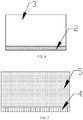
- an area of the base plate 100 equals to an area of the test board 1, the base plate 100 is arranged on a light-emitting surface of the LED light source 10; the dispersive prism area 4 and the diffusion plate 5 are arranged on a light-emitting surface of the base plate 100, that is, the surface of the base plate 100 against the LED light source 10; as shown in FIG.s 4 and 7 , according to a position of the lamp bead shadow area 2, arranging a dispersive prism area 4 correspondingly on the base plate 100, and an area that the dispersive prism area 4 covers on the base plate 100 equals to an area of the rectangular test area.
- the dispersive prism comprises three quadrangular surfaces (a first quadrangular surface, a second quadrangular surface and a third quadrangular surface, respectively) and two triangular surfaces, while the first quadrangular surface of the dispersive prism is stuck by an adhesive on the base plate 100, a plurality of dispersive prisms are arranged in a matrix, and two adjacent dispersive prisms are in contact.
- an area that the diffusion plates 5 covers on the base plate 100 equals to the area of the rectangular test area.
- the diffusion plate 5 comprises a coating layer 105 and a plurality of diffusion particles 102, placing a coating layer 105 with an area equals to the rectangular test area at a position of the base plate 100 corresponding to the non-lamp bead shadow area 3, and arranging a plurality of diffusion particles 102 on a surface of the coating layer 105 against the base plate 100, while the plurality of diffusion particles 102 are arranged in a matrix, with a space between two of the diffusion particles 102 in adjacent, and the diffusion particles 102 is sphere shaped.
- the design method further comprises a plurality of steps:
- the first diffusion particles 103 are hemispherical shaped, while a plane of the first diffusion particle 103 contacts with the second quadrangular surface and the third quadrangular surface of the dispersive prism, so as to facilitate a fixing and installation of the first diffusion particles 103 onto the dispersive prism.
- a diameter of the first diffusion particles 103 is 3 ⁇ m to 5 ⁇ m, the first diffusion particles 103 on the second quadrangular surface and the third quadrangular surface are all far away from the base plate 100, that is, the plurality of first diffusion particles 103 are distributed at a tip of the dispersive prism, and a height of a coverage area of the plurality of first diffusion particles 103 on the dispersive prism is 1/3 of a height of the dispersive prism, so as to increase a diffusion of a light output from the dispersive prism, and decrease a phenomenon of glare or rainbow pattern of the light emitted by the dispersive prism.
- a size and a structure of the dispersive prisms 101 distributed in the dispersive prisms area 4 are same, a height of the dispersive prism 101 is 30 ⁇ m, and a vertex angle of the dispersive prism 101 is 90°.
- the dispersive prism area 4 comprises a plurality of first dispersive prisms 106 and a plurality of second dispersive prisms 107, a height of the second dispersive prisms 107 is smaller than a height of the first dispersive prisms 106, the first dispersive prism 106 and the second dispersive prism 107 are arranged alternately, and adjacent two dispersive prisms of the first dispersive prisms 106 and the second dispersive prism 107 are in contact, making the dispersive prisms in the dispersive prism area 4 are arranged in a dithering way, which further destroys a uniformity of the dispersive prisms emitting light and increases the diffusivity of the light emitted by the dispersive prisms, so as to weaken the glare and the
- a distance between the top of the first dispersive prism 106 and the top of the second dispersive prism 107 is 30 ⁇ m to 50 ⁇ m, both apex angles of the first dispersive prism 106 and the second dispersive prism 107 are 90°, the height of the second dispersive prism 107 is 20 ⁇ m, and the height of the first dispersive prism 106 is 30 ⁇ m.
- the base plate 100 is a PET base plate
- the coating layer 105 is a UV photosensitive adhesive coating layer
- a diameter of both the diffusion particles 102 and the second diffusion particles 104 is 2 ⁇ m to 8 ⁇ m.
- both the lamp bead shadow area 2 and the non-lamp bead shadow area 3 are obtained.
- the dispersive prisms areas 4 and lamp bead shadow areas 2 are corresponding to each other, and the diffusion pate 5 are corresponding to the non-lamp bead shadow area 3.
- both the lamp bead shadow area 2 and the non-lamp bead shadow area 3 are obtained.
- the dispersive prisms areas 4 and lamp bead shadow areas 2 are corresponding to each other and the diffusion pate 5 are corresponding to the non-lamp bead shadow area 3.
- the present disclosure further provides a composite membrane, wherein comprising a base plate 100, the base plate 100 is applied to corresponding to a light source, a light-emitting surface of the base plate 100 has a plurality of dispersive prism areas 4 and a plurality of diffusion plates 5 arranged, while the dispersive prism areas 4 are corresponding to the lamp bead shadow areas 2, and the diffusion plates 5 are corresponding to the non-lamp bead shadow areas 3.
- the dispersive prism area 4 comprises a plurality of dispersive prisms 101 arranged in a matrix, a first quadrangular surface of the dispersive prism 101 attaches to the base plate, a surface against the base plate 100 of a second quadrangular surface and a third quadrangular surface of the dispersive prism 101 has a plurality of first diffusion particles 103 arranged.
- the first diffusion particles 103 are hemispherical shaped, while a plane of the first diffusion particle 103 is in contact with the second quadrangular surface and the third quadrangular surface of the dispersive prism 101.
- a diameter of the first diffusion particles 103 is 3 ⁇ m to 5 ⁇ m, the first diffusion particles 103 on the second quadrangular surface and the third quadrangular surface are all far away from the base plate 100, that is, the plurality of first diffusion particles 103 are distributed at a tip of the dispersive prism, and a height of a coverage area of the plurality of first diffusion particles 103 on the dispersive prism is 1/3 of a height of the dispersive prism, so as to increase a diffusion of a light output from the dispersive prism 101, and decrease a phenomenon of glare or rainbow pattern of the light emitted by the dispersive prism 101.
- the diffusion plate 5 comprises a coating layer 105 arranged on the light-emitting surface of the base plate 100 and a plurality of diffusion particles 102 arranged on a surface of the coating layer 105 against the base plate 100, the plurality of diffusion particles 102 are arranged in a matrix, and the diffusion particles 102 is sphere shaped.
- the dispersive prism area 4 comprises a plurality of first dispersive prisms 106 and a plurality of second dispersive prisms 107, a height of the second dispersive prisms 107 is smaller than a height of the first dispersive prisms 106, the first dispersive prism 106 and the second dispersive prism 107 are arranged alternately.
- a distance between the top of the first dispersive prism 106 and the top of the second dispersive prism 107 is 30 ⁇ m to 50 ⁇ m, both apex angles of the first dispersive prism 106 and the second dispersive prism 107 are 90°, the height of the second dispersive prism 107 is 20 ⁇ m, and the height of the first dispersive prism 106 is 30 ⁇ m.
- a shape of the second diffusion particles is a sphere
- the base plate 100 is a PET base plate
- the coating layer 105 is a UV photosensitive adhesive coating layer
- a diameter of both the diffusion particles 102 and the second diffusion particles 104 is 2 ⁇ m to 8 ⁇ m.
- the present disclosure provides a design method for a composite membrane and a composite membrane, comprising a plurality of steps: arranging a test board on a light-emitting surface of a plurality of LED light sources, and turning on the LED light sources; establishing a rectangular test area corresponding to each of the LED light sources on the test board, and detecting a brightness uniformity on each of the rectangular test areas; comparing the brightness uniformity with a preset value, defining a rectangular test area having the brightness uniformity less than the preset value as a lamp bead shadow area; and defining a rectangular test area having the brightness uniformity greater than the preset value, and a plurality of areas on the test board other than the rectangular test areas as a non-lamp bead shadow area; arranging a base plate on a light-emitting surface of the plurality of LED light sources, and arranging a plurality of dispersive prism areas and a plurality of diffusion plates on a light-emitting surface of the base plate respectively, while making an
- the present disclosure provides a design method for a composite membrane and a composite membrane, by arranging a plurality of dispersive prism areas and a plurality of diffusion plates on the light-emitting surface of the base plate, while making the dispersive prism areas correspond to the lamp bead shadow areas, and the diffusion plates correspond to the non-lamp bead shadow areas. Arranging the dispersive prism areas in an area with an uneven light energy distribution, while laying out the diffusion plates only in an area with an even light energy distribution, without any needs to lay the dispersive prisms, so as to improve a phenomenon of uneven visual effects and reduce a production cost.
Landscapes
- Physics & Mathematics (AREA)
- General Physics & Mathematics (AREA)
- Optics & Photonics (AREA)
- Spectroscopy & Molecular Physics (AREA)
- Planar Illumination Modules (AREA)
Abstract
Description
- The present disclosure relates to the technical field of backlight modules, and more particularly, to a design method for a composite membrane and the composite membrane.
- Due to a limitation of lens technology and a trend requirement of cost reduction, for a backlight module having a same size, a number of a plurality of LED light sources used is becoming less and less, while a space between the LED light sources increases accordingly, which makes both a direct-lit backlight module and a side-lit backlight module have a problem of an uneven visual effect. For the direct-lit backlight module, a poor light mixing may appear in the visual effect, which is shown as a light spot phenomenon including a plurality of bright spots or a plurality of dark spots on a lamp; for the side-lit backlight module, it is shown as a lamp bead shadow problem including a plurality of bright lights and a plurality of dark lights alternating in the visual effect.
- Therefore, the present technology needs to be improved and developed
- A technical problem to be solved by the present disclosure is that, in view of the defects described above in the prior art, providing a design method for a composite membrane and the composite membrane, aimed at improving the phenomenon of uneven visual effect of the backlight module.
- The technical solutions of the present disclosure are as follows:
- A design method for a composite membrane, wherein comprising a plurality of steps:
- arranging a test board on a light-emitting surface of a plurality of LED light sources, and turning on the LED light sources;
- establishing a rectangular test area corresponding to each of the LED light sources on the test board, and detecting a brightness uniformity on each of the rectangular test areas;
- comparing the brightness uniformity with a preset value, defining a rectangular test area having the brightness uniformity less than the preset value as a lamp bead shadow area; and defining both a rectangular test area having the brightness uniformity greater than the preset value, and a plurality of areas on the test board other than the rectangular test areas, as a non-lamp bead shadow area;
- arranging a base plate on a light-emitting surface of the plurality of LED light sources, and arranging a plurality of dispersive prism areas and a plurality of diffusion plates on a light-emitting surface of the base plate respectively, while making the dispersive prism areas correspond to the lamp bead shadow areas, and making the diffusion plates correspond to the non-lamp bead shadow areas.
- The design method for the composite membrane, wherein the step of establishing the rectangular test area corresponding to each of the LED light sources on the test board, and detecting the brightness uniformity on each of the rectangular test areas, comprises specifically:
- establishing a rectangular test area corresponding to each of the LED light sources on the test board;
- selecting nine test points arranged in three rows and three columns in the rectangular test area, and detecting a brightness of the nine test points respectively;
- calculating a ratio of a sum of the brightness of the nine test points except for a middle test point to the brightness of the middle test point, and obtaining the brightness uniformity of the rectangular test area.
- The design method for the composite membrane, wherein a test point in middle of the nine test points is corresponding to a center of the LED light source.
- The design method for the composite membrane, wherein the test point in middle of the nine test points locates at a center of the rectangular test area, a space between every two adjacent rows of the LED light sources is equal, and a space between every two adjacent columns of the LED light sources is equal.
- The design method for the composite membrane, wherein the step of arranging the base plate on the light-emitting surface of the plurality of LED light sources, and arranging the plurality of dispersive prism areas and the plurality of diffusion plates on the light-emitting surface of the base plate respectively, while making the dispersive prism areas correspond to the lamp bead shadow areas, and the diffusion plates correspond to the non-lamp bead shadow areas, comprises specifically:
- arranging the base plate on the light-emitting surface of the plurality of LED light sources, fixing a first quadrangular surface of a plurality of dispersive prisms to the light-emitting surface of the base plate, and arranging the plurality of dispersive prisms into a dispersive prism matrix corresponding to an area and a position according to the areas and the positions of the lamp bead shadow;
- arranging a coating layer with an equal area on a light-emitting surface of the base plate at a position corresponding to the non-lamp bead shadow, and arranging a plurality of diffusion particles on the coating layer, while the plurality of diffusion particles are arranged in a matrix.
- The design method for the composite membrane, wherein further comprises a plurality of steps of:
- fixing a plurality of first diffusion particles on both the second quadrangular surface and the third quadrangular surface of the dispersive prisms;
- arranging a coating layer on a light incidence surface of the base plate;
- arranging a plurality of second diffusion particles on a surface of the coating layer against the base plate.:
- The design method for the composite membrane, wherein the dispersive prism area comprises a plurality of first dispersive prisms and a plurality of second dispersive prisms, a height of the second dispersive prisms is smaller than a height of the first dispersive prisms, the first dispersive prisms and the second dispersive prisms are arranged alternately.
- A composite membrane, wherein comprising a base plate, the base plate is applied to corresponding to a light source, a light-emitting surface of the base plate has a plurality of dispersive prism areas and a plurality of diffusion plates arranged, while the dispersive prism areas are corresponding to the lamp bead shadow areas, and the diffusion plates are corresponding to the non-lamp bead shadow areas.
- The composite membrane, wherein the base plate is a PET base plate.
- The composite membrane, wherein the diffusion plate comprises a coating layer arranged on the light-emitting surface of the base plate, and a plurality of diffusion particles arranged on a surface of the coating layer against the base plate.
- The composite membrane, wherein the coating layer is a UV photosensitive adhesive coating layer.
- The composite membrane, wherein the dispersive prism area comprises a plurality of dispersive prisms arranged in a matrix, a first quadrangular surface of the dispersive prism attaches to the base plate, a surface against the base plate of a second quadrangular surface and a third quadrangular surface of the dispersive prism has a plurality of first diffusion particles arranged.
- The composite membrane, wherein the first diffusion particles are hemispherical shaped, while the second quadrangular surface and the third quadrangular surface of the dispersive prism are in contact with a plane of the first diffusion particle, correspondingly and respectively.
- The composite membrane, wherein the dispersive prism area comprises a plurality of first dispersive prisms and a plurality of second dispersive prisms, a height of the second dispersive prism is smaller than a height of the first dispersive prism, while the first dispersive prism and the second dispersive prism are arranged alternately.
- The composite membrane, wherein a distance from a top of the first dispersive prism and a top of the second dispersive prism is 30µm - 50µm.
- Benefits: The present disclosure arranges a plurality of dispersive prism areas and a plurality of diffusion plates on the light-emitting surface of the base plate, while the dispersive prism areas are corresponding to the lamp bead shadow areas, and the diffusion plates are corresponding to the non-lamp bead shadow areas. Arranging the dispersive prism areas in an area with an uneven light energy distribution, while laying out the diffusion plates only in an area with an even light energy distribution, without any needs to lay the dispersive prisms, so as to improve a phenomenon of uneven visual effects and reduce a production cost.
-
-
FIG.1 illustrates a flowchart on a design method for the composite membrane in the present disclosure; -
FIG.2 illustrates a schematic structural diagram on a direct-lit backlight module in the present disclosure; -
FIG.3 illustrates a schematic diagram on a distribution of a lamp bead shadow areas and a non-lamp bead shadow areas on a test board of the direct-lit backlight module in the present disclosure. -
FIG.4 illustrates a schematic diagram on a distribution of a plurality of dispersive prism areas and a diffusion plates on the composite membrane corresponding to the direct-lit backlight module in the present disclosure. -
FIG.5 illustrates a schematic structural diagram on a side-lit backlight module in the present disclosure; -
FIG.6 illustrates a schematic diagram on a distribution of the lamp bead shadow areas and the non-lamp bead shadow areas on the test board of the side-lit backlight module in the present disclosure. -
FIG.7 illustrates a schematic diagram on a distribution of the dispersive prism areas and the diffusion plates on the composite membrane corresponding to the side-lit backlight module in the present disclosure. -
FIG.8 illustrates a schematic diagram on a distribution of the nine test points in the rectangular test area of the present disclosure. -
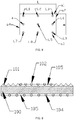
FIG.9 illustrates a schematic structural diagram on the composite membrane in a preferred embodiment of the present disclosure. -
FIG.10 illustrates a schematic structural diagram on the composite membrane in another preferred embodiment of the present disclosure. -
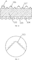
FIG.11 illustrates a schematic diagram on a partial enlargement at point A inFIG. 10 . - In order to make the purposes technical solutions, and effects of the present disclosure clearer and more specific, the present disclosure will be described in further details below. It should be understood that the specific embodiments described herein are only used to explain the present disclosure and are not intended to limit the present disclosure.
- Referencing to
FIG.s 1-11 , wherein a plurality of arrows inFIG. 2 andFIG. 5 illustrates a light emitting direction. -
Embodiment 1 - The present disclosure provides a design method for a composite membrane, shown as
FIG. 1 , comprising a plurality of steps below: - S100, arranging a
test board 1 on a light-emitting surface of a plurality ofLED light sources 10, and turning on theLED light sources 10. - In a preferred embodiment, as shown in
FIG. 2 andFIG.5 , the composite membrane is suitable for both a direct-lit backlight module and a side-lit backlight module; for the direct-lit backlight module, thetest board 1 in the present disclosure is a diffusion plate; for the side-lit backlight module, thetest board 1 in the present disclosure is a light guide plate. In the direct-lit backlight module, the plurality ofLED light sources 10 are arranged in a matrix on a back plate, and a total rectangular area covered by the plurality ofLED light sources 10 on the back plate has an area smaller than an area of a surface of thetest board 1 facing toward theLED light source 10, and the area of the surface of thetest board 1 facing toward theLED light source 10 increases following a distance increase between thetest board 1 and theLED light source 10, that is, the smaller a distance between thetest board 1 and theLED light source 10 is, the smaller an area of thetest board 1 needed is; the bigger the distance between thetest board 1 and theLED light source 10 is, the bigger the area of thetest board 1 needed is. - S200, establishing a rectangular test area corresponding to each of the
LED light sources 10 on thetest board 1, and detecting a brightness uniformity on each of the rectangular test areas. - The step S200 comprises specifically:
- S201, establishing a rectangular test area corresponding to each of the
LED light sources 10 on thetest board 1; - specifically, establishing a rectangular test area correspondingly on the
test board 1 for eachLED light source 10, and by checking a brightness uniformity of each rectangular test area, it is decided that whether the rectangular test area belongs to a lamp bead shadow area 2 (a non-uniform visual effect area) or a non-lamp bead shadow area 3 (a uniform visual effect area), so as to determine whether setting adispersive prism area 4 correspondingly or setting adiffusing plate 5 correspondingly according to a position and an area of the rectangular test area. - The rectangular test area faces to the
LED light source 10 directly, and the rectangular test area covers completely an area where theLED light source 10 generates a light shadow on thetest board 1; preferably, a center point of the rectangular test area corresponds to a center point of theLED light source 10, a length of the rectangular test area is L, and a width thereof is H. - S202, selecting nine test points arranged in three rows and three columns in the rectangular test area, and detecting a brightness of the nine test points respectively.
- Specifically, shown as
FIG. 8 , selecting nine test points in the rectangular test area: L1, L2, L3, L4, L5, L6, L7, L8, and L9, while the nine test points are arranged in three rows and three columns, a space between every two adjacent rows is equal, and a space between every two adjacent columns is equal. That is, a distance between L1 and L2 equals to a distance between L2 and L3, a distance between L1 and L4 equals to a distance between L4 and L7. A test point locates in middle of the nine test points is L5, a center of theLED light source 10 corresponding to the rectangular test area is against the L5, and L5 also locates at a center of the rectangular test area. - The rectangular test area comprises a first side a1, a second side a2, a third side a3, and a fourth side a4 connecting end to end in a sequence, wherein a length of the first side a1 is L, a length of the second side a2 is H. A row that L1, L2, L3 locates is parallel to the first side a1, a column that L1, L4, L7 locates is parallel to the second side a2. While a distance between L1 and the first side a1 equals to a distance between L7 and the third side a3, and a distance between L1 and the fourth side a4 equals to a distance between L3 and the second side a2.
- In an embodiment, the distance between L1 and the first side a1 is H/10, a distance between L1 and L2 is 0.4L, the distance between L1 and the fourth side a4 is L/10, both a distance between L2 and the second side a2 and a distance between L2 and the fourth side a4 is L/2, both a distance between L5 and the first side a1 and a distance between L5 and the third side a3 is H/2; detecting a brightness at each of the test points according to a position of the nine test points, wherein, a brightness of the test point L1 is A1, a brightness of the test point L2 is A2, a brightness of the test point L3 is A3, a brightness of the test point L4 is A4, a brightness of the test point L5 is A5, a brightness of the test point L6 is A6, a brightness of the test point L7 is A7, a brightness of the test point L8 is A8.
- S203, calculating a ratio of a sum of the brightness of the nine test points except for a middle test point to the brightness of the middle test point, and obtaining the brightness uniformity of the rectangular test area.
- Specifically, after obtaining the brightness of each test point, calculating the sum of the brightness of all the test points except for the middle test point, taking the middle test point as L5, that is, calculating a sum S of the A1, A2, A3, A4, A6, A7, A8 and A9; followed by calculating the ratio of S to the brightness of the test point L5, that is, by calculating S/A5, the brightness uniformity of the rectangular test area will be obtained.
- S300, comparing the brightness uniformity with a preset value, defining a rectangular test area having the brightness uniformity less than the preset value as the lamp
bead shadow area 2; and defining the rectangular test area having the brightness uniformity greater than the preset value, and the plurality of areas on thetest board 1 other than the rectangular test areas as the non-lampbead shadow area 3; - Specifically, comparing the brightness uniformity of each rectangular test area with the preset value, to determine whether the rectangular test area is the lamp bead shadow area or the non-lamp bead shadow area. Preferably, the preset value is 80 %, when the brightness uniformity is less than 80%, the rectangular test area corresponding to the brightness uniformity is the lamp
bead shadow area 2, a light energy is unevenly distributed, and it is needed to set thedispersive prism area 4; when the brightness uniformity is greater than 80%, the rectangular test area corresponding to the brightness uniformity is the non-lampbead shadow area 3, the light energy distributes evenly, and only thediffusion plates 5 are needed to lay to improve the light energy uniformity in this area, without a need to lay a dispersive prism, thus a production cost is reduced, while improving a phenomenon of an uneven visual effect at a same time; a plurality of areas on thetest board 1 other than all of the rectangular test areas are the non-lampbead shadow areas 3. - S400, arranging a
base plate 100 on a light-emitting surface of the plurality ofLED light sources 10, and arranging a plurality ofdispersive prism areas 4 and a plurality ofdiffusion plates 5 on a light-emitting surface of thebase plate 100 respectively, while making thedispersive prism areas 4 correspond to the lampbead shadow areas 2, and thediffusion plates 5 correspond to the non-lampbead shadow areas 3. - The step S400 comprises specifically:
- S401, arranging the
base plate 100 on the light-emitting surface of the plurality ofLED light sources 10, fixing a first quadrangular surface of a plurality of dispersive prisms to the light-emitting surface of thebase plate 100, and arranging the plurality of dispersive prisms into a dispersive prism matrix corresponding to an area and a position according to the areas and the positions of the lamp bead shadow; - S402, arranging a
coating layer 105 with an equal area on the light-emitting surface of the base plate at a position corresponding to the non-lamp bead shadow, and arranging a plurality ofdiffusion particles 102 on thecoating layer 105, while the plurality ofdiffusion particles 102 are arranged in a matrix. - Specifically, an area of the
base plate 100 equals to an area of thetest board 1, thebase plate 100 is arranged on a light-emitting surface of theLED light source 10; thedispersive prism area 4 and thediffusion plate 5 are arranged on a light-emitting surface of thebase plate 100, that is, the surface of thebase plate 100 against theLED light source 10; as shown inFIG.s 4 and7 , according to a position of the lampbead shadow area 2, arranging adispersive prism area 4 correspondingly on thebase plate 100, and an area that thedispersive prism area 4 covers on thebase plate 100 equals to an area of the rectangular test area. The dispersive prism comprises three quadrangular surfaces (a first quadrangular surface, a second quadrangular surface and a third quadrangular surface, respectively) and two triangular surfaces, while the first quadrangular surface of the dispersive prism is stuck by an adhesive on thebase plate 100, a plurality of dispersive prisms are arranged in a matrix, and two adjacent dispersive prisms are in contact. - Based on a position of the non-lamp
bead shadow area 3, arranging a plurality ofdiffusion plates 5 at a plurality of positions on the basedboard 100 accordingly, an area that thediffusion plates 5 covers on thebase plate 100 equals to the area of the rectangular test area. Thediffusion plate 5 comprises acoating layer 105 and a plurality ofdiffusion particles 102, placing acoating layer 105 with an area equals to the rectangular test area at a position of thebase plate 100 corresponding to the non-lampbead shadow area 3, and arranging a plurality ofdiffusion particles 102 on a surface of thecoating layer 105 against thebase plate 100, while the plurality ofdiffusion particles 102 are arranged in a matrix, with a space between two of thediffusion particles 102 in adjacent, and thediffusion particles 102 is sphere shaped. - The design method further comprises a plurality of steps:
- fixing a plurality of
first diffusion particles 103 on both a second quadrangular surface and a third quadrangular surface of the dispersive prisms; - arranging a
coating layer 105 on a light incidence surface of thebase plate 100; - arranging a plurality of
second diffusion particles 104 on a surface of thecoating layer 105 against thebase plate 100. - Specifically, the
first diffusion particles 103 are hemispherical shaped, while a plane of thefirst diffusion particle 103 contacts with the second quadrangular surface and the third quadrangular surface of the dispersive prism, so as to facilitate a fixing and installation of thefirst diffusion particles 103 onto the dispersive prism. A diameter of thefirst diffusion particles 103 is 3 µm to 5 µm, thefirst diffusion particles 103 on the second quadrangular surface and the third quadrangular surface are all far away from thebase plate 100, that is, the plurality offirst diffusion particles 103 are distributed at a tip of the dispersive prism, and a height of a coverage area of the plurality offirst diffusion particles 103 on the dispersive prism is 1/3 of a height of the dispersive prism, so as to increase a diffusion of a light output from the dispersive prism, and decrease a phenomenon of glare or rainbow pattern of the light emitted by the dispersive prism. - In a preferred embodiment of the embodiment, as shown in
FIG. 9 , a size and a structure of thedispersive prisms 101 distributed in thedispersive prisms area 4 are same, a height of thedispersive prism 101 is 30 µm, and a vertex angle of thedispersive prism 101 is 90°. - In another preferred implementation of the embodiment, as shown in
FIG.s 10 and 11 , the sizes of thedispersive prisms 101 distributed in thedispersive prism area 4 are not completely same, thedispersive prism area 4 comprises a plurality of firstdispersive prisms 106 and a plurality of seconddispersive prisms 107, a height of the seconddispersive prisms 107 is smaller than a height of the firstdispersive prisms 106, the firstdispersive prism 106 and the seconddispersive prism 107 are arranged alternately, and adjacent two dispersive prisms of the firstdispersive prisms 106 and the seconddispersive prism 107 are in contact, making the dispersive prisms in thedispersive prism area 4 are arranged in a dithering way, which further destroys a uniformity of the dispersive prisms emitting light and increases the diffusivity of the light emitted by the dispersive prisms, so as to weaken the glare and the rainbow patterns. Preferably, a distance between the top of the firstdispersive prism 106 and the top of the seconddispersive prism 107 is 30 µm to 50 µm, both apex angles of the firstdispersive prism 106 and the seconddispersive prism 107 are 90°, the height of the seconddispersive prism 107 is 20 µm, and the height of the firstdispersive prism 106 is 30 µm. - coating a
coating layer 105 on a light incidence surface of thebase plate 100, arranging thecoating layer 105 completely covering the light incidence surface of thesubstrate plate 100, and arranging a plurality ofsecond diffusion particles 104 on a surface of thecoating layer 105 against thebase plate 100, to increase a foggy feeling and a wear resistance of the light incidence surface of thebase plate 100. The plurality ofsecond diffusion particles 104 are arranged in a matrix, with a gap between two adjacentsecond diffusion particles 104; a structure of thesecond diffusion particles 104 is as same as the structure of thediffusion particles 102. Preferably, thebase plate 100 is a PET base plate, thecoating layer 105 is a UV photosensitive adhesive coating layer, and a diameter of both thediffusion particles 102 and thesecond diffusion particles 104 is 2 µm to 8 µm. - Taking the direct-lit backlight module as an example, as shown in
FIG.s 3 and4 , according to a division of the rectangular test area and a calculation of the brightness uniformity, both the lampbead shadow area 2 and the non-lampbead shadow area 3 are obtained. Arranging a diffusion plate between thebase plate 100 and theLED light sources 10, and on thebase plate 100, thedispersive prisms areas 4 and lampbead shadow areas 2 are corresponding to each other, and thediffusion pate 5 are corresponding to the non-lampbead shadow area 3. - Taking the side-lit backlight module as an example, as shown in
FIG.s 6 and 7 , according to a division of the rectangular test area and a calculation of the brightness uniformity, both the lampbead shadow area 2 and the non-lampbead shadow area 3 are obtained. Arranging a diffusion plate between thebase plate 100 and theLED light sources 10, and on thebase plate 100, thedispersive prisms areas 4 and lampbead shadow areas 2 are corresponding to each other and thediffusion pate 5 are corresponding to the non-lampbead shadow area 3. - The present disclosure further provides a composite membrane, wherein comprising a
base plate 100, thebase plate 100 is applied to corresponding to a light source, a light-emitting surface of thebase plate 100 has a plurality ofdispersive prism areas 4 and a plurality ofdiffusion plates 5 arranged, while thedispersive prism areas 4 are corresponding to the lampbead shadow areas 2, and thediffusion plates 5 are corresponding to the non-lampbead shadow areas 3. - In a preferred embodiment, shown as
FIG. 9 , thedispersive prism area 4 comprises a plurality ofdispersive prisms 101 arranged in a matrix, a first quadrangular surface of thedispersive prism 101 attaches to the base plate, a surface against thebase plate 100 of a second quadrangular surface and a third quadrangular surface of thedispersive prism 101 has a plurality offirst diffusion particles 103 arranged. Thefirst diffusion particles 103 are hemispherical shaped, while a plane of thefirst diffusion particle 103 is in contact with the second quadrangular surface and the third quadrangular surface of thedispersive prism 101. A diameter of thefirst diffusion particles 103 is 3 µm to 5 µm, thefirst diffusion particles 103 on the second quadrangular surface and the third quadrangular surface are all far away from thebase plate 100, that is, the plurality offirst diffusion particles 103 are distributed at a tip of the dispersive prism, and a height of a coverage area of the plurality offirst diffusion particles 103 on the dispersive prism is 1/3 of a height of the dispersive prism, so as to increase a diffusion of a light output from thedispersive prism 101, and decrease a phenomenon of glare or rainbow pattern of the light emitted by thedispersive prism 101. - The
diffusion plate 5 comprises acoating layer 105 arranged on the light-emitting surface of thebase plate 100 and a plurality ofdiffusion particles 102 arranged on a surface of thecoating layer 105 against thebase plate 100, the plurality ofdiffusion particles 102 are arranged in a matrix, and thediffusion particles 102 is sphere shaped. - In a preferred embodiment, shown as
FIG. 10 , thedispersive prism area 4 comprises a plurality of firstdispersive prisms 106 and a plurality of seconddispersive prisms 107, a height of the seconddispersive prisms 107 is smaller than a height of the firstdispersive prisms 106, the firstdispersive prism 106 and the seconddispersive prism 107 are arranged alternately. Preferably, a distance between the top of the firstdispersive prism 106 and the top of the seconddispersive prism 107 is 30 µm to 50 µm, both apex angles of the firstdispersive prism 106 and the seconddispersive prism 107 are 90°, the height of the seconddispersive prism 107 is 20 µm, and the height of the firstdispersive prism 106 is 30 µm. - Arranging a
coating layer 105 on a light incidence surface of thebase plate 100, and arranging a plurality ofsecond diffusion particles 104 into a matrix on a surface of thecoating layer 105 against thebase plate 100, a shape of the second diffusion particles is a sphere, thebase plate 100 is a PET base plate, thecoating layer 105 is a UV photosensitive adhesive coating layer, and a diameter of both thediffusion particles 102 and thesecond diffusion particles 104 is 2 µm to 8 µm. - All above, the present disclosure provides a design method for a composite membrane and a composite membrane, comprising a plurality of steps: arranging a test board on a light-emitting surface of a plurality of LED light sources, and turning on the LED light sources; establishing a rectangular test area corresponding to each of the LED light sources on the test board, and detecting a brightness uniformity on each of the rectangular test areas; comparing the brightness uniformity with a preset value, defining a rectangular test area having the brightness uniformity less than the preset value as a lamp bead shadow area; and defining a rectangular test area having the brightness uniformity greater than the preset value, and a plurality of areas on the test board other than the rectangular test areas as a non-lamp bead shadow area; arranging a base plate on a light-emitting surface of the plurality of LED light sources, and arranging a plurality of dispersive prism areas and a plurality of diffusion plates on a light-emitting surface of the base plate respectively, while making an area of the dispersive prism areas correspond to that of the lamp bead shadow areas, and an area and a position of the diffusion plates area correspond to the non-lamp bead shadow areas, improving a visual effects while reducing a production cost.
- It should be understood that the application of the present disclosure is not limited to the above examples. For those skilled in the art, improvements or changes can be made according to the above description, and all such improvements and changes should fall within the protection scope of the appended claims of the present disclosure.
- The present disclosure provides a design method for a composite membrane and a composite membrane, by arranging a plurality of dispersive prism areas and a plurality of diffusion plates on the light-emitting surface of the base plate, while making the dispersive prism areas correspond to the lamp bead shadow areas, and the diffusion plates correspond to the non-lamp bead shadow areas. Arranging the dispersive prism areas in an area with an uneven light energy distribution, while laying out the diffusion plates only in an area with an even light energy distribution, without any needs to lay the dispersive prisms, so as to improve a phenomenon of uneven visual effects and reduce a production cost.
Claims (15)
- A design method for a composite membrane, wherein comprising a plurality of steps:arranging a test board on a light-emitting surface of a plurality of LED light sources, and turning on the LED light sources;establishing a rectangular test area corresponding to each of the LED light sources on the test board, and detecting a brightness uniformity on each of the rectangular test areas;comparing the brightness uniformity with a preset value, defining a rectangular test area having the brightness uniformity less than the preset value as a lamp bead shadow area; and defining both a rectangular test area having the brightness uniformity greater than the preset value, and a plurality of areas on the test board other than the rectangular test areas as a non-lamp bead shadow area;arranging a base plate on a light-emitting surface of the plurality of LED light sources, and arranging a plurality of dispersive prism areas and a plurality of diffusion plates on a light-emitting surface of the base plate respectively, while making the dispersive prism areas correspond to the lamp bead shadow areas, and making the diffusion plates correspond to the non-lamp bead shadow areas.
- The design method for the composite membrane according to claim 1, wherein the step of establishing the rectangular test area corresponding to each of the LED light sources on the test board, and detecting the brightness uniformity on each of the rectangular test areas, comprises specifically:establishing a rectangular test area corresponding to each of the LED light sources on the test board;selecting nine test points arranged in three rows and three columns in the rectangular test area, and detecting a brightness of the nine test points respectively;calculating a ratio of a sum of the brightness of the nine test points except for a middle test point to the brightness of the middle test point, and obtaining the brightness uniformity of the rectangular test area.
- The design method for the composite membrane according to claim 2, wherein a test point in middle of the nine test points is corresponding to a center of the LED light source.
- The design method for the composite membrane according to claim 2, wherein a test point in middle of the nine test points locates at a center of the rectangular test area, a space between every two adjacent rows of the LED light sources is equal, and a space between every two adjacent columns of the LED light sources is equal.
- The design method for the composite membrane according to claim 1, wherein the step of arranging the base plate on the light-emitting surface of the plurality of LED light sources, and arranging the plurality of dispersive prism areas and the plurality of diffusion plates on the light-emitting surface of the base plate respectively, while making the dispersive prism areas correspond to the lamp bead shadow areas, and the diffusion plates correspond to the non-lamp bead shadow areas, comprises specifically:arranging the base plate on the light-emitting surface of the plurality of LED light sources, fixing a first quadrangular surface of a plurality of dispersive prisms to the light-emitting surface of the base plate, and arranging the plurality of dispersive prisms into a dispersive prism matrix corresponding to an area and a position according to the areas and the positions of the lamp bead shadow;arranging a coating layer with an equal area on a light-emitting surface of the base plate at a position corresponding to the non-lamp bead shadow, and arranging a plurality of diffusion particles on the coating layer, while the plurality of diffusion particles are arranged in a matrix.
- The design method for the composite membrane according to claim 5, wherein further comprises a plurality of steps of:fixing a plurality of first diffusion particles on both the second quadrangular surface and the third quadrangular surface of the dispersive prisms;arranging a coating layer on a light incidence surface of the base plate;arranging a plurality of second diffusion particles on a surface of the coating layer against the base plate.:
- The design method for the composite membrane according to claim 1, wherein the dispersive prism area comprises a plurality of first dispersive prisms and a plurality of second dispersive prisms, a height of the second dispersive prisms is smaller than a height of the first dispersive prisms, the first dispersive prisms and the second dispersive prisms are arranged alternately.
- A composite membrane, wherein comprising a base plate, the base plate is applied to corresponding to a light source, a light-emitting surface of the base plate has a plurality of dispersive prism areas and a plurality of diffusion plates arranged, while the dispersive prism areas are corresponding to a plurality of lamp bead shadow areas, and the diffusion plates are corresponding to a plurality of non-lamp bead shadow areas.
- The composite membrane according to claim 8, wherein the base plate is a PET base plate.
- The composite membrane according to claim 8, wherein the diffusion plate comprises a coating layer arranged on the light-emitting surface of the base plate, and a plurality of diffusion particles arranged on a surface of the coating layer against the base plate.
- The composite membrane according to claim 10, wherein the coating layer is a UV photosensitive adhesive coating layer.
- The composite membrane according to claim 8, wherein the dispersive prism area comprises a plurality of dispersive prisms arranged in a matrix, a first quadrangular surface of the dispersive prism attaches to the base plate, a surface against the base plate of a second quadrangular surface and a third quadrangular surface of the dispersive prism has a plurality of first diffusion particles arranged.
- The composite membrane according to claim 12, wherein the first diffusion particles are hemispherical shaped, while the second quadrangular surface and the third quadrangular surface of the dispersive prism are in contact with a plane of the first diffusion particle, correspondingly and respectively.
- The composite membrane according to claim 8, wherein the dispersive prism area comprises a plurality of first dispersive prisms and a plurality of second dispersive prisms, a height of the second dispersive prism is smaller than a height of the first dispersive prism, while the first dispersive prism and the second dispersive prism are arranged alternately.
- The composite membrane according to claim 14, wherein a distance from a top of the first dispersive prism and a top of the second dispersive prism is 30µm - 50µm.
Applications Claiming Priority (2)
| Application Number | Priority Date | Filing Date | Title |
|---|---|---|---|
| CN201810730811.5A CN108957606B (en) | 2018-07-05 | 2018-07-05 | Design method of composite diaphragm and composite diaphragm |
| PCT/CN2019/093433 WO2020007233A1 (en) | 2018-07-05 | 2019-06-28 | Design method for composite membrane and composite membrane |
Publications (2)
| Publication Number | Publication Date |
|---|---|
| EP3819683A1 true EP3819683A1 (en) | 2021-05-12 |
| EP3819683A4 EP3819683A4 (en) | 2021-08-25 |
Family
ID=64486017
Family Applications (1)
| Application Number | Title | Priority Date | Filing Date |
|---|---|---|---|
| EP19831124.3A Pending EP3819683A4 (en) | 2018-07-05 | 2019-06-28 | COMPOSITE MEMBRANE AND ITS DESIGN PROCESS |
Country Status (4)
| Country | Link |
|---|---|
| US (1) | US11947137B2 (en) |
| EP (1) | EP3819683A4 (en) |
| CN (1) | CN108957606B (en) |
| WO (1) | WO2020007233A1 (en) |
Families Citing this family (3)
| Publication number | Priority date | Publication date | Assignee | Title |
|---|---|---|---|---|
| CN108957606B (en) | 2018-07-05 | 2021-03-30 | 深圳创维-Rgb电子有限公司 | Design method of composite diaphragm and composite diaphragm |
| KR102711325B1 (en) * | 2019-07-03 | 2024-09-30 | 삼성전자주식회사 | Display appartus and diffuser plate thereof |
| CN111045253B (en) * | 2019-12-30 | 2021-12-28 | 华为技术有限公司 | Backlight module and liquid crystal display device |
Family Cites Families (24)
| Publication number | Priority date | Publication date | Assignee | Title |
|---|---|---|---|---|
| CN100405170C (en) * | 2003-04-01 | 2008-07-23 | 鸿富锦精密工业(深圳)有限公司 | Direct type backlight module and its diffusion plate |
| US20070110386A1 (en) | 2005-11-12 | 2007-05-17 | Tien-Hon Chiang | Device having combined diffusing, collimating, and color mixing light control function |
| US20090311486A1 (en) * | 2006-12-18 | 2009-12-17 | Kolon Industries, Inc. | Optical sheets |
| CN101452086A (en) * | 2007-12-05 | 2009-06-10 | 群康科技(深圳)有限公司 | Prismatic lens, back light module unit and LCD device |
| CN201166306Y (en) * | 2008-02-26 | 2008-12-17 | 光耀科技股份有限公司 | Diffusion sheet with light-gathering function |
| KR20110033052A (en) * | 2009-09-23 | 2011-03-30 | 신화인터텍 주식회사 | Prism Sheet and Backlight Assembly Having Same |
| CN101957464A (en) * | 2010-10-12 | 2011-01-26 | 丹阳博昱科技有限公司 | Optical sheet and application thereof |
| TWI416223B (en) * | 2010-11-19 | 2013-11-21 | Advanced Optoelectronic Tech | Backlight unit |
| KR101374362B1 (en) * | 2010-12-23 | 2014-03-17 | 제일모직주식회사 | Optical film, backlight unit and display apparatus using the same |
| WO2013008797A1 (en) | 2011-07-14 | 2013-01-17 | シャープ株式会社 | Surface light emitting device, and display device |
| TWI459043B (en) * | 2011-10-04 | 2014-11-01 | Au Optronics Corp | Optical film and backlight module using the same |
| WO2013115020A1 (en) | 2012-01-30 | 2013-08-08 | シャープ株式会社 | Illuminating apparatus, display apparatus, and television receiver |
| CN102736146B (en) * | 2012-06-30 | 2014-12-10 | 合肥乐凯科技产业有限公司 | Optical diffusion film and backlight module for liquid crystal display |
| CN203396970U (en) * | 2012-12-28 | 2014-01-15 | 合肥乐凯科技产业有限公司 | Novel brightening and diffusing composite film |
| CN103048709A (en) * | 2012-12-28 | 2013-04-17 | 合肥乐凯科技产业有限公司 | Composite brightness enhancement and diffusion membrane |
| CN203413546U (en) * | 2013-06-28 | 2014-01-29 | 3M材料技术(广州)有限公司 | Optical film layer, backlight module and liquid crystal display device |
| CN203744019U (en) * | 2014-02-20 | 2014-07-30 | 北京京东方视讯科技有限公司 | Backlight source, backlight module and display device |
| CN104456312B (en) * | 2014-12-02 | 2016-08-24 | 京东方科技集团股份有限公司 | A kind of backlight, display floater and display device |
| CN106886067A (en) * | 2015-12-15 | 2017-06-23 | 宁波长阳科技股份有限公司 | A kind of composite brightening film and preparation method thereof |
| CN106908874B (en) * | 2016-01-14 | 2019-04-05 | 宁波长阳科技股份有限公司 | A kind of composite brightening film and backlight module |
| CN206594324U (en) | 2017-02-20 | 2017-10-27 | 张家港康得新光电材料有限公司 | A kind of anti-scratch brightness enhancement film of haze |
| CN206990985U (en) | 2017-07-11 | 2018-02-09 | 江苏双星彩塑新材料股份有限公司 | A kind of diffusion composite membrane for LCD backlight module |
| CN107621728A (en) * | 2017-09-21 | 2018-01-23 | 六安驰瑞复合材料有限公司 | A kind of bright enhancement film |
| CN108957606B (en) | 2018-07-05 | 2021-03-30 | 深圳创维-Rgb电子有限公司 | Design method of composite diaphragm and composite diaphragm |
-
2018
- 2018-07-05 CN CN201810730811.5A patent/CN108957606B/en active Active
-
2019
- 2019-06-28 EP EP19831124.3A patent/EP3819683A4/en active Pending
- 2019-06-28 US US16/970,076 patent/US11947137B2/en active Active
- 2019-06-28 WO PCT/CN2019/093433 patent/WO2020007233A1/en not_active Ceased
Also Published As
| Publication number | Publication date |
|---|---|
| CN108957606A (en) | 2018-12-07 |
| US20230152499A1 (en) | 2023-05-18 |
| CN108957606B (en) | 2021-03-30 |
| US11947137B2 (en) | 2024-04-02 |
| WO2020007233A1 (en) | 2020-01-09 |
| EP3819683A4 (en) | 2021-08-25 |
Similar Documents
| Publication | Publication Date | Title |
|---|---|---|
| JP5140922B2 (en) | Light emitting light source and light emitting light source array | |
| US9341766B2 (en) | Lighting device, display device and television device | |
| CN108572481B (en) | Backlight module and display device | |
| US7402940B2 (en) | Surface light emitting apparatus | |
| TWI847278B (en) | Optical film and back light unit including the same | |
| US7967460B2 (en) | Planar light source and backlight unit including the same | |
| US11947137B2 (en) | Method for composite membrane and composite membrane | |
| KR101948141B1 (en) | backlight unit and illumination system using the same | |
| US20090290093A1 (en) | Planar light-emitting device and liquid crystal display apparatus | |
| US20080031006A1 (en) | Light guide plate and liquid crystal display device having the same | |
| CN101978293A (en) | Optical element, light source unit including the optical element, and liquid crystal display device | |
| KR101580581B1 (en) | Optical film, light source assembly including the same, and method of fabricating mold for optical film | |
| CN114137764A (en) | Backlight module and display device | |
| CN106547047A (en) | A kind of light guide plate, backlight module and display device | |
| US7766533B2 (en) | Illumination module, and a display and general lighting apparatus using the same | |
| JP2016143668A (en) | Backlight assembly and liquid crystal display device including the same | |
| US8049845B2 (en) | Optical diffusion device | |
| US12072576B2 (en) | Backlight module and display device | |
| JP4635863B2 (en) | Surface emitting device | |
| KR20150110896A (en) | Optical Plate and Backlight Assembly having the Same | |
| US11914245B2 (en) | Light source unit, display device, and light source unit manufacturing apparatus | |
| KR20170142681A (en) | Light guide panel for the direct type BLU | |
| KR102435736B1 (en) | Reflective diffusing lens and light emitting module comprising the same | |
| CN201531825U (en) | Combined light guiding board | |
| KR100953696B1 (en) | Composite optical sheet and backlight unit having same |
Legal Events
| Date | Code | Title | Description |
|---|---|---|---|
| STAA | Information on the status of an ep patent application or granted ep patent |
Free format text: STATUS: THE INTERNATIONAL PUBLICATION HAS BEEN MADE |
|
| PUAI | Public reference made under article 153(3) epc to a published international application that has entered the european phase |
Free format text: ORIGINAL CODE: 0009012 |
|
| STAA | Information on the status of an ep patent application or granted ep patent |
Free format text: STATUS: REQUEST FOR EXAMINATION WAS MADE |
|
| 17P | Request for examination filed |
Effective date: 20200820 |
|
| AK | Designated contracting states |
Kind code of ref document: A1 Designated state(s): AL AT BE BG CH CY CZ DE DK EE ES FI FR GB GR HR HU IE IS IT LI LT LU LV MC MK MT NL NO PL PT RO RS SE SI SK SM TR |
|
| A4 | Supplementary search report drawn up and despatched |
Effective date: 20210727 |
|
| RIC1 | Information provided on ipc code assigned before grant |
Ipc: G02B 5/02 20060101AFI20210721BHEP Ipc: G02B 5/04 20060101ALI20210721BHEP Ipc: G01J 1/10 20060101ALI20210721BHEP Ipc: G02F 1/1335 20060101ALI20210721BHEP Ipc: G01J 3/50 20060101ALN20210721BHEP |
|
| DAV | Request for validation of the european patent (deleted) | ||
| DAX | Request for extension of the european patent (deleted) | ||
| STAA | Information on the status of an ep patent application or granted ep patent |
Free format text: STATUS: EXAMINATION IS IN PROGRESS |
|
| 17Q | First examination report despatched |
Effective date: 20230419 |