EP3819653B1 - Method for testing a receive chain of a magnetic resonance tomograph - Google Patents
Method for testing a receive chain of a magnetic resonance tomograph Download PDFInfo
- Publication number
- EP3819653B1 EP3819653B1 EP19207566.1A EP19207566A EP3819653B1 EP 3819653 B1 EP3819653 B1 EP 3819653B1 EP 19207566 A EP19207566 A EP 19207566A EP 3819653 B1 EP3819653 B1 EP 3819653B1
- Authority
- EP
- European Patent Office
- Prior art keywords
- signal
- level
- magnetic resonance
- frequency
- receiver
- Prior art date
- Legal status (The legal status is an assumption and is not a legal conclusion. Google has not performed a legal analysis and makes no representation as to the accuracy of the status listed.)
- Active
Links
- 238000012360 testing method Methods 0.000 title claims description 49
- 238000000034 method Methods 0.000 title claims description 35
- 238000004458 analytical method Methods 0.000 claims description 24
- 238000003325 tomography Methods 0.000 claims description 8
- 101001091538 Homo sapiens Pyruvate kinase PKM Proteins 0.000 claims 1
- 102100034911 Pyruvate kinase PKM Human genes 0.000 claims 1
- 238000005259 measurement Methods 0.000 description 12
- 230000008878 coupling Effects 0.000 description 11
- 238000010168 coupling process Methods 0.000 description 11
- 238000005859 coupling reaction Methods 0.000 description 11
- 238000012545 processing Methods 0.000 description 10
- 238000011156 evaluation Methods 0.000 description 9
- 230000003321 amplification Effects 0.000 description 8
- 238000003199 nucleic acid amplification method Methods 0.000 description 8
- 230000005540 biological transmission Effects 0.000 description 7
- 230000006870 function Effects 0.000 description 6
- 230000008859 change Effects 0.000 description 5
- 230000001419 dependent effect Effects 0.000 description 5
- 238000010586 diagram Methods 0.000 description 5
- 230000005284 excitation Effects 0.000 description 5
- 239000011159 matrix material Substances 0.000 description 5
- 230000003068 static effect Effects 0.000 description 5
- 230000015556 catabolic process Effects 0.000 description 4
- 230000006835 compression Effects 0.000 description 4
- 238000007906 compression Methods 0.000 description 4
- 238000006731 degradation reaction Methods 0.000 description 4
- 238000003745 diagnosis Methods 0.000 description 4
- 230000035945 sensitivity Effects 0.000 description 4
- 230000009466 transformation Effects 0.000 description 4
- 238000006243 chemical reaction Methods 0.000 description 3
- 238000001514 detection method Methods 0.000 description 3
- 238000003384 imaging method Methods 0.000 description 3
- 238000005481 NMR spectroscopy Methods 0.000 description 2
- 230000008901 benefit Effects 0.000 description 2
- 238000004364 calculation method Methods 0.000 description 2
- 230000006866 deterioration Effects 0.000 description 2
- 230000003247 decreasing effect Effects 0.000 description 1
- 238000002059 diagnostic imaging Methods 0.000 description 1
- 230000004069 differentiation Effects 0.000 description 1
- 230000009977 dual effect Effects 0.000 description 1
- 230000000694 effects Effects 0.000 description 1
- 230000005672 electromagnetic field Effects 0.000 description 1
- 230000007613 environmental effect Effects 0.000 description 1
- 230000005281 excited state Effects 0.000 description 1
- 230000004907 flux Effects 0.000 description 1
- 230000007274 generation of a signal involved in cell-cell signaling Effects 0.000 description 1
- 238000002595 magnetic resonance imaging Methods 0.000 description 1
- 238000013507 mapping Methods 0.000 description 1
- 238000001225 nuclear magnetic resonance method Methods 0.000 description 1
- 230000004044 response Effects 0.000 description 1
- 238000005070 sampling Methods 0.000 description 1
- 238000011896 sensitive detection Methods 0.000 description 1
- 238000000926 separation method Methods 0.000 description 1
- 238000004088 simulation Methods 0.000 description 1
- 230000003595 spectral effect Effects 0.000 description 1
- 238000012546 transfer Methods 0.000 description 1
- 238000000844 transformation Methods 0.000 description 1
Images


Classifications
-
- G—PHYSICS
- G01—MEASURING; TESTING
- G01R—MEASURING ELECTRIC VARIABLES; MEASURING MAGNETIC VARIABLES
- G01R33/00—Arrangements or instruments for measuring magnetic variables
- G01R33/20—Arrangements or instruments for measuring magnetic variables involving magnetic resonance
- G01R33/28—Details of apparatus provided for in groups G01R33/44 - G01R33/64
- G01R33/32—Excitation or detection systems, e.g. using radio frequency signals
- G01R33/36—Electrical details, e.g. matching or coupling of the coil to the receiver
-
- A—HUMAN NECESSITIES
- A61—MEDICAL OR VETERINARY SCIENCE; HYGIENE
- A61B—DIAGNOSIS; SURGERY; IDENTIFICATION
- A61B5/00—Measuring for diagnostic purposes; Identification of persons
- A61B5/05—Detecting, measuring or recording for diagnosis by means of electric currents or magnetic fields; Measuring using microwaves or radio waves
- A61B5/055—Detecting, measuring or recording for diagnosis by means of electric currents or magnetic fields; Measuring using microwaves or radio waves involving electronic [EMR] or nuclear [NMR] magnetic resonance, e.g. magnetic resonance imaging
-
- G—PHYSICS
- G01—MEASURING; TESTING
- G01R—MEASURING ELECTRIC VARIABLES; MEASURING MAGNETIC VARIABLES
- G01R33/00—Arrangements or instruments for measuring magnetic variables
- G01R33/0023—Electronic aspects, e.g. circuits for stimulation, evaluation, control; Treating the measured signals; calibration
-
- G—PHYSICS
- G01—MEASURING; TESTING
- G01R—MEASURING ELECTRIC VARIABLES; MEASURING MAGNETIC VARIABLES
- G01R33/00—Arrangements or instruments for measuring magnetic variables
- G01R33/20—Arrangements or instruments for measuring magnetic variables involving magnetic resonance
- G01R33/28—Details of apparatus provided for in groups G01R33/44 - G01R33/64
- G01R33/32—Excitation or detection systems, e.g. using radio frequency signals
- G01R33/34—Constructional details, e.g. resonators, specially adapted to MR
- G01R33/34038—Loopless coils, i.e. linear wire antennas
-
- G—PHYSICS
- G01—MEASURING; TESTING
- G01R—MEASURING ELECTRIC VARIABLES; MEASURING MAGNETIC VARIABLES
- G01R33/00—Arrangements or instruments for measuring magnetic variables
- G01R33/20—Arrangements or instruments for measuring magnetic variables involving magnetic resonance
- G01R33/28—Details of apparatus provided for in groups G01R33/44 - G01R33/64
- G01R33/32—Excitation or detection systems, e.g. using radio frequency signals
- G01R33/36—Electrical details, e.g. matching or coupling of the coil to the receiver
- G01R33/3607—RF waveform generators, e.g. frequency generators, amplitude-, frequency- or phase modulators or shifters, pulse programmers, digital to analog converters for the RF signal, means for filtering or attenuating of the RF signal
-
- G—PHYSICS
- G01—MEASURING; TESTING
- G01R—MEASURING ELECTRIC VARIABLES; MEASURING MAGNETIC VARIABLES
- G01R33/00—Arrangements or instruments for measuring magnetic variables
- G01R33/20—Arrangements or instruments for measuring magnetic variables involving magnetic resonance
- G01R33/28—Details of apparatus provided for in groups G01R33/44 - G01R33/64
- G01R33/32—Excitation or detection systems, e.g. using radio frequency signals
- G01R33/36—Electrical details, e.g. matching or coupling of the coil to the receiver
- G01R33/3621—NMR receivers or demodulators, e.g. preamplifiers, means for frequency modulation of the MR signal using a digital down converter, means for analog to digital conversion [ADC] or for filtering or processing of the MR signal such as bandpass filtering, resampling, decimation or interpolation
-
- G—PHYSICS
- G01—MEASURING; TESTING
- G01R—MEASURING ELECTRIC VARIABLES; MEASURING MAGNETIC VARIABLES
- G01R33/00—Arrangements or instruments for measuring magnetic variables
- G01R33/20—Arrangements or instruments for measuring magnetic variables involving magnetic resonance
- G01R33/28—Details of apparatus provided for in groups G01R33/44 - G01R33/64
- G01R33/32—Excitation or detection systems, e.g. using radio frequency signals
- G01R33/36—Electrical details, e.g. matching or coupling of the coil to the receiver
- G01R33/3664—Switching for purposes other than coil coupling or decoupling, e.g. switching between a phased array mode and a quadrature mode, switching between surface coil modes of different geometrical shapes, switching from a whole body reception coil to a local reception coil or switching for automatic coil selection in moving table MR or for changing the field-of-view
-
- G—PHYSICS
- G01—MEASURING; TESTING
- G01R—MEASURING ELECTRIC VARIABLES; MEASURING MAGNETIC VARIABLES
- G01R33/00—Arrangements or instruments for measuring magnetic variables
- G01R33/20—Arrangements or instruments for measuring magnetic variables involving magnetic resonance
- G01R33/28—Details of apparatus provided for in groups G01R33/44 - G01R33/64
- G01R33/32—Excitation or detection systems, e.g. using radio frequency signals
- G01R33/36—Electrical details, e.g. matching or coupling of the coil to the receiver
- G01R33/3692—Electrical details, e.g. matching or coupling of the coil to the receiver involving signal transmission without using electrically conductive connections, e.g. wireless communication or optical communication of the MR signal or an auxiliary signal other than the MR signal
-
- G—PHYSICS
- G01—MEASURING; TESTING
- G01R—MEASURING ELECTRIC VARIABLES; MEASURING MAGNETIC VARIABLES
- G01R33/00—Arrangements or instruments for measuring magnetic variables
- G01R33/20—Arrangements or instruments for measuring magnetic variables involving magnetic resonance
- G01R33/44—Arrangements or instruments for measuring magnetic variables involving magnetic resonance using nuclear magnetic resonance [NMR]
- G01R33/48—NMR imaging systems
Definitions
- the invention relates to a method for operating a magnetic resonance tomograph, with which the correct functioning of a reception path of the magnetic resonance tomograph can be checked.
- Magnetic resonance tomographs are imaging devices which, in order to image an examination object, align nuclear spins of the examination object with a strong external magnetic field and excite them to precess around this alignment by means of an alternating magnetic field. The precession or return of the spins from this excited state to a lower-energy state in turn generates an alternating magnetic field in response, which is received by antennas.
- a spatial coding is impressed on the signals, which subsequently enables the received signal to be assigned to a volume element.
- the signal received is then evaluated and a three-dimensional imaging representation of the examination object is provided.
- local receiving antennas so-called local coils, are preferably used, which are arranged directly on the examination object to achieve a better signal-to-noise ratio.
- the receiving antennas can also be installed in a patient couch.
- the image quality is sensitively dependent on the proper functioning of a reception path from the antenna to digitization and evaluation. Even minor deteriorations, such as those that can gradually occur as a result of increased contact resistance on plug connections or degradation of components, lead to reduced image quality and increased time required for image acquisition.
- a nuclear magnetic resonance method is known, with which an object located in a static homogeneous magnetic field is irradiated with high-frequency electromagnetic pulses to obtain nuclear magnetic resonance signals, which are received with receiving means and demodulated, after which the demodulated resonance signals are sampled to obtain sampled values and from the sampled values a nuclear magnetic resonance distribution is determined.
- Non-linear distortion of the resonance signals due to distortion in the receiving means which in themselves have an almost linear transfer function, due to distortion of the sampled resonance signals, are compensated for with the aid of a counter-distortion function, which has a counter-distortion effect for the non-linear distortion.
- the document EP 1 664 820 A1 describes a dynamic adjustment of the receiver sensitivity during a magnetic resonance recording.
- a reference high-frequency signal is added to the reception path by an additional antenna.
- the reference signal is preferably set in such a way that its frequency is at the edge of the frequency band M recorded by the magnetic resonance tomograph.
- a comparison of the previously known amplitude and phase of the reference signal with the amplitude and phase of the received reference signal allows to determine the distortions introduced with the set sensitivity and subsequently to eliminate them.
- the method includes receiving a magnetic resonance signal with a radio frequency reception channel and correcting the magnetic resonance signal with a signal mapping function of the radio frequency reception channel.
- a local coil with a test device for a magnetic resonance tomograph and a system made up of a magnetic resonance tomograph and local coil and a method for operation are known.
- the local coil has a first connection for connection to the magnetic resonance tomograph and a test device for testing a system made up of the local coil and the magnetic resonance tomograph connected to it.
- the test device is designed to detect a test signal in the local coil.
- the object is achieved by a method according to claim 1 according to the invention.
- the magnetic resonance tomograph has a receiver and a transmitter.
- the transmitter is designed to generate and output a first two-tone signal having a first frequency f1 and a second frequency f2, the first frequency f1 being unequal to the second frequency f2.
- the frequency spacing is at least large enough for the signal components at f1 and f2 to be separated by the receiver, ie there is a relative amplitude minimum between the amplitude at f1 and the amplitude at f2.
- the frequency spacing can be greater than 100 Hz, 1 kHz, 10 kHz or 100 kHz, for example.
- the first frequency f1, the second frequency f2 and a 3rd order intermodulation product (IM3) or higher order of the first frequency f1 and the second frequency f2 lie in a common reception range of the receiver, preferably at a Larmor frequency of the magnetic resonance tomograph, which is caused by a static magnetic field strength B0 and the magnetic moment of the nuclear spin to be examined is given.
- intermodulation products of odd order for example 3rd order 5th order or generally (2n+1)th order with n as a natural number greater than or equal to 1
- the receiving range can be up to 1 kHz, 10 kHz, 100 kHz, 1 MHz or 5 MHz wide, for example, with the width being defined by an attenuation greater than 6 dB, 12 dB or more outside the range.
- the received signal is converted in frequency by mixing or digital signal processing. According to the invention, it is also considered to be in the receiving range of the receiver if signals with original frequencies f1, f2 and the frequency of the intermodulation product can be recorded and evaluated by the receiver after frequency conversion.
- a level of the output two-tone signal is in a level range in which the received two-tone signal at the receiver still lies in the linear range of the receiver as the upper limit.
- the linear range can be viewed as the range with a maximum compression of the characteristic curve of less than 0.1 dB or 1 dB.
- the level of the receiver's inherent noise or a signal distance of the IM3 to this noise level of 3 dB, 6 dB or more is regarded as the lower limit of the level range.
- the output of the signal by the transmitter can be transmission via an antenna, for example a body coil, or via another electrical or magnetic antenna as an alternating electromagnetic field.
- an antenna for example a body coil
- another electrical or magnetic antenna as an alternating electromagnetic field.
- diagnosis as explained in more detail in the dependent claims, that the output signal is coupled in directly via a signal loop at different diagnosis points, for example galvanically, inductively or capacitively.
- the levels of the two-tone signals required at the feed point then depend on the amplification or attenuation on the signal path between the feed point and the receiver.
- the transmitter can be the transmitter of the magnetic resonance tomograph for exciting the nuclear spins, provided that its output level can be reduced sufficiently. Sufficient linearity is required, even in the lower power range. It is also conceivable that the required small signal is generated directly from the input signal of the output stage, bypassing the output stage. However, it would also be possible to provide a separate transmitter for generating the two-tone signals or to provide a linear small-signal amplifier in the transmitter instead of the power output stage.
- the magnetic resonance tomograph is designed to emit a second two-tone signal, the level of which differs from the first two-tone signal.
- the method according to the invention is intended for functional testing of a reception chain of the magnetic resonance tomograph.
- the reception chain can include all elements in the signal path from the antenna, for example local coil or body coil, to digitization in the receiver and the subsequent image reconstruction. However, it is also conceivable that only parts of it are checked, for example in order to localize an error more closely.
- the transmitter controlled by a controller of the magnetic resonance tomograph, emits a first two-tone signal at a first level.
- the outputting can be a transmission via an antenna or, for example, a coupling via a signal loop into a diagnosis point of a reception path.
- the level of the first two-tone signal is predetermined in such a way that it is at least above a noise level of the receiver when it has passed through the signal path to the receiver or the analysis device.
- an analysis device detects a first intermodulation product via the signal loop.
- the analysis device is provided by components of the magnetic resonance tomograph, for example a receiver for the magnetic resonance signals for processing the high-frequency and the subsequent signal processing of the image reconstruction for evaluation by a Fourier transformation, for example.
- the signal loop can include all components of the reception path from an antenna coil to the receiver, or just parts of a diagnosis point on the reception path to the receiver in order to localize a fault more closely.
- high-frequency processing and signal analysis to take place in a separate analysis device.
- amplitudes of IM3 and at f1 and f2 are detected.
- the transmitter emits a second two-tone signal at a second level.
- the second two-tone signal differs in level from the first two-tone signal. For example, it may have a level at least 3 dB, 6 dB, 12 dB higher, or higher as long as the linear range condition as previously defined is met.
- the level change also advantageously takes place in the same direction for both frequencies f1 and f2 of the two-tone signal, so that a change in the intermodulation signal of the odd order, in particular the third order, is not partially compensated for.
- the analysis device detects a second intermodulation product via the signal loop.
- a second intermodulation product via the signal loop.
- the order of the first and second two-tone signal is interchangeable, i.e. whether it is initially sent with a higher level or a lower one only changes the subsequent determination slightly.
- a test value is determined as a function of the level of the first two-tone signal, the level of the second two-tone signal, a level of the first intermodulation product and a level of the second intermodulation product.
- the analysis device compares the determined test value with a predetermined reference value.
- the predetermined test value can be determined, for example, by a reference measurement during commissioning, in the laboratory, or from simulations. The comparison can also be made by controlling the magnetic resonance tomograph, so that this is part of the analysis device.
- a signal is output to an operator on an output device or a signal to a controller of the magnetic resonance tomograph depending on the comparison. If the signal indicates a deviation from the reference value that leads to image degradation, then the controller or operator can interrupt image acquisition. A service measure can also be initiated to rectify the error. It is also conceivable that the controller repeats the steps of the method with a modified signal loop, as explained in relation to the subclaims below.
- a magnetic resonance tomograph with a transmitter with a two-tone signal using the method according to the invention makes it possible to detect deteriorations in the reception chain at an early stage by means of the odd-order, in particular third-order intermodulation product, which is sensitive to changes.
- the different levels allow variations in the level, e.g. when coupling, to be eliminated in the evaluation.
- the magnetic resonance tomograph has an analysis device.
- the analysis facility is designed to determine a level of the intermodulation product in an input signal.
- the analysis device can be part of the image reconstruction, for example. However, a dedicated signal processor or a signal processing component of the receiver is also conceivable.
- the level of the intermodulation product can be determined, for example, by means of an analog or digital filter and subsequent amplitude measurement, or directly by means of Fourier transformation of the digitized signal.
- the intermodulation product advantageously enables a particularly sensitive detection of deviations in the reception chain.
- the magnetic resonance tomograph has a signal loop.
- the signal loop is designed to couple the two-tone signal of the transmitter into a component of a reception path of the receiver. Any signal connection that conducts a two-tone signal output by the transmitter via one or more components of a reception path of the magnetic resonance tomograph to the receiver, in particular the receiver for magnetic resonance signals, including the signal processing steps contained therein, is regarded as a signal loop.
- the magnetic resonance tomograph has a local coil.
- the signal loop includes the local coil, in other words, the two-tone signal is coupled into the local coil and runs through the reception path to the receiver.
- the signal loop encloses an antenna coil of the local coil, ie the two-tone signal is inductively coupled into the antenna coil.
- the local coil has a diagnostic connection for connection to the signal loop, so that a diagnostic signal can be electrically coupled in directly.
- the two-tone signal can also be coupled in optically and converted into an electrical signal by a photoelectric converter.
- the magnetic resonance tomograph advantageously also allows the function of the local coil to be checked.
- the magnetic resonance tomograph has a signal splitter in the signal path.
- the signal splitter can be implemented, for example, by one or more electronic or mechanical switches, which can also be connected in a matrix.
- the signal splitter has at least one signal input for the two-tone signal and at least two signal outputs that can be connected to the signal input by the controller.
- a controller of the magnetic resonance tomograph is designed to couple the two-tone signal of the transmitter into different components of the reception path by means of the signal splitter.
- the signal outputs of the signal splitter can be connected directly to the local coil and a connection of the local coil to the receiver. By feeding the two-tone signal once into the local coil and once directly into the receiver, the signal splitter makes it possible to localize a fault in the local coil.
- the signal splitter advantageously allows faults to be localized on individual sections of the reception path.
- the step of determining a test value includes determining an OIP3 (Output Intermodulation Intercept Point 3).
- OIP3 is a virtual point in a double-logarithmic amplifier characteristic, in which the 3rd order intermodulation product of two signals of a two-tone signal would be equal in amplitude to the basic signals of the two-tone signal.
- the OIP3 can be calculated from the values for interpolate detected amplitudes of two two-tone signals of different levels and the amplitudes of the 3rd order intermodulation product generated thereby.
- the OIP3 is independent of the exact coupling strength of the transmitter in the reception loop and at the same time sensitive to changes in the reception path, so that changes and errors can be easily detected.
- the magnetic resonance tomograph has a signal splitter, with the step of setting the signal splitter being performed by the controller before the step of outputting a two-tone signal.
- the step of setting the signal splitter being performed by the controller before the step of outputting a two-tone signal.
- an output of the signal splitter is coupled to a component of the reception path, thus creating a signal loop from the transmitter via the signal splitter to the receiver, so that a two-tone signal can reach the receiver and be evaluated there.
- the signal loop can be closed via different components by the signal splitter, and a possible error can thus be localized by repeating the method with different signal loops.
- FIG. 1 shows a schematic representation of an embodiment of a magnetic resonance tomograph 1 for use in a method according to the invention.
- the magnet unit 10 has a field magnet 11 that generates a static magnetic field B0 for aligning nuclear spins of samples or of the patient 100 in a recording area.
- the recording area is characterized by an extremely homogeneous static magnetic field B0, with the homogeneity particularly affecting the magnetic field strength or the amount.
- the recording area is almost spherical and is arranged in a patient tunnel 16, which extends in a longitudinal direction 2 extends through the magnet unit 10.
- a patient bed 30 can be moved in the patient tunnel 16 by the traversing unit 36 .
- the field magnet 11 is usually a superconducting magnet that can provide magnetic fields with a magnetic flux density of up to 3T, and even more in the case of the latest devices. For lower field strengths, however, permanent magnets or electromagnets with normally conducting coils can also be used.
- the magnet unit 10 has gradient coils 12 which are designed to superimpose variable magnetic fields in three spatial directions on the magnetic field B0 for spatial differentiation of the recorded imaging regions in the examination volume.
- the gradient coils 12 are usually coils made from normally conducting wires, which can generate mutually orthogonal fields in the examination volume.
- the magnet unit 10 also has a body coil 14 which is designed to emit a high-frequency signal supplied via a signal line into the examination volume and to receive resonance signals emitted by the patient 100 and emit them via a signal line.
- a control unit 20 supplies the magnet unit 10 with the various signals for the gradient coils 12 and the body coil 14 and evaluates the received signals.
- control unit 20 has a gradient control 21, which is designed to supply the gradient coils 12 with variable currents via supply lines, which provide the desired gradient fields in the examination volume in a time-coordinated manner.
- control unit 20 has a high-frequency unit 22 which is designed to generate a high-frequency pulse with a predetermined time profile, amplitude and spectral power distribution for exciting a magnetic resonance of the nuclear spins in the patient 100 .
- a high-frequency unit 22 which is designed to generate a high-frequency pulse with a predetermined time profile, amplitude and spectral power distribution for exciting a magnetic resonance of the nuclear spins in the patient 100 .
- Pulse powers in the kilowatt range can be achieved.
- the excitation pulses can be radiated into the patient 100 via the body coil 14 or via a local transmitting antenna.
- a controller 23 communicates with the gradient controller 21 and the radio-frequency unit 22 via a signal bus 25.
- a local coil 50 is arranged on the patient 100 and is connected to the high-frequency unit 22 and its receiver 65 via a connecting line 33 .
- the results of a magnetic resonance tomography depend strongly on the reception quality, in particular on the signal-to-noise ratio (SNR).
- SNR signal-to-noise ratio
- the SNR can gradually deteriorate due to component degradation without immediate failures occurring. However, this can change the image quality or the required measurement time. It is therefore advantageous if the sensitivity of the components involved in reception is tested at least before each image acquisition in the configuration intended for image acquisition using the magnetic resonance tomograph.
- IM3 third-order intermodulation product
- the signal generated by the test transmitter 60 itself preferably has no or only a negligible proportion of an IM3 signal, for example with an attenuation of 20 dB, 40 dB, 60 dB or more. In this way, the IM3 signal can be assigned to the reception path in the receiver and evaluated more easily, since it is not a change that can be considered in the analysis, but essentially the amount.
- FIG. 1 shows an embodiment of a method for evaluating the reception chain in a schematic diagram.
- An input level is plotted horizontally on a logarithmic scale. This can correspond to the level of one of the two input signals of the two-tone signal with the frequencies f1 and f2 or be derived from both.
- the levels are preferably equal or in a fixed ratio to one another in order to facilitate evaluation.
- the input level can then be represented by a single value on the horizontal axis.
- the corresponding output levels L a are measured for each input level.
- IM3 non-linear amplification
- the input level Le is preferably chosen such that the output levels La or IM3 are above a noise level L n of the reception loop. In this way, a total of 4 points are obtained for two different input levels.
- a characteristic of the amplification of the entire reception loop is defined by the points L a1 and L a2 and a straight line through these points. This bends into a horizontal line due to compression at the upper end of the linear range, where the output level is independent of the input signal level due to saturation.
- the input levels L e are preferably selected in such a way that the output levels are below this kink in the linear range of the receiving loop. It is also conceivable to use a large number of input levels L e and to measure the associated output level L a or IM3 and to select only the pairs of values that are in the linear range and above the noise level.
- the intermodulation products also increase with the input level, but due to the higher order also with higher exponents, with IM3 steeper by a factor of 3.
- a straight line is also defined here by two points IM3 1 and IM3 2 . Because of the different gradients, the straight lines for the linear components L a and IM3 intersect at a point that is referred to as the 3rd order Intercept Point 3 (IP3). Even if this point cannot actually be measured because of the onset of compression, it is nevertheless characteristic of the amplification properties of the receiving loop.
- IP3 3rd order Intercept Point 3
- the principle of the invention is not limited to the IP3 here.
- intersections of a higher, odd order such as IP5 or IP7 can also be used.
- a large number of mathematically equivalent calculations are also conceivable within the scope of the method according to the invention, which eliminate variable factors of the method, such as the coupling strength, by using a number of measuring points for the linear output signal and the intermodulation product.
- the embodiment shown was chosen here in particular because of its clearness in the diagram.
- the high-frequency unit 22 generates the two-tone signal with the frequencies f 1 and f 2 and emits them via the body coil 14 .
- the high-frequency unit 22 is designed to generate signals with a frequency around the Larmor frequency in order to excite the nuclear spins. It is necessary for the high-frequency unit 22 to be designed to also generate signals with a sufficiently low amplitude and sufficient linearity so that they do not overdrive the receiver 65 or drive into compression and at the same time do not already produce an IM3 signal with an appreciable amplitude generated. Details of the transmission part or the test transmitter 60 are to 6 explained in more detail.
- the two-tone signal is inductively coupled into the receiving loop via the local coil 50 or its antenna coil.
- all components of the reception path involved in reception can be routed via the antenna coil and LNB of the local coil 50, signal connections, plugs, switching matrix to towards the receiver 65 are checked.
- the controller 23 of the magnetic resonance tomograph 1 can control the generation of the two-tone signal by the high-frequency unit 22 and the evaluation of the signal received by the receiver 65 according to the method according to the invention.
- test transmitter 60 has a switch or a switching matrix with which the two-tone signal can be selectively coupled into the receiving loop at different points.
- Two feed points with capacitive coupling are given here as an example.
- One feed point is at the input of the LNB in the local coil 50, the other at the input to the receiver 65.
- the test transmitter 60 can be the same transmitter that is also used to excite the nuclear spins, only parts of it such as transmission signal processing without a power output stage, or a dedicated test transmitter with independent signal generation.
- a separate test transmitter 60 can be optimized particularly easily in terms of linearity.
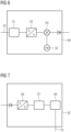
- a test transmitter 60 is shown schematically, as is conceivable both as an integrated transmitter for exciting the nuclear spins (at least in the signal processing) or as a dedicated test transmitter 60 .
- the test transmitter 60 has a transmission memory 61 into which the controller 23 can write a transmission signal via the signal bus 25 .
- this can be an envelope curve or explicitly a signal in a baseband in the form of a sequence of real or complex amplitude values.
- the signal is read out by a D/A converter 62 and converted into an analog signal.
- the signal is converted into the desired frequency range f MR around the Larmor frequency.
- the test signal differs from an excitation signal for the nuclear spins essentially by the subsequent amplification. While signals with a few microwatts to milliwatts with high linearity are required for the method according to the invention, depending on the coupling, an output stage for excitation must provide hundreds of watts to kilowatts of power.
- the test transmitter 60 can therefore also be provided as part of a transmitter for nuclear spin excitation with or without a special low-power output stage
- a receiver 65 is shown, as is also used to receive the MR signals.
- the incoming analog signal is amplified and filtered if necessary. Conversion to an intermediate frequency or baseband is also conceivable, which can take place in the receiver or in a preceding stage such as the local coil 50.
- the analog signal is digitized by an A/D converter 66, by a signal processor 67 or by an FPGA digitally further processed and made available in digitized form in a receiving memory 68 of the controller 23, which can access it via the signal bus 25.
- the separation of the frequencies f 1 , f 2 and the IM3 as well as the assessment of the level can be done, for example already take place in the signal processor 67 or only through the controller 23.
- a possible analogue or digital frequency conversion is also taken into account in the evaluation, by means of which the frequencies f 1 , f 2 and those of the IM3 are converted into the baseband.
- the test transmitter outputs a first two-tone signal.
- the properties of the test transmitter and the two-tone signal have already been explained in detail for the preceding figures.
- the transmission can take place via an antenna or directly through an electrical signal connection in the reception path.
- the test signal is routed via the signal loop provided in this way from the test transmitter 60 to the analysis device, preferably the receiver 65, for detection.
- the signal switch for example a switching matrix
- the signal switch is set in order to feed the test signal via the switching matrix at a predetermined point and thus to close the signal loop.
- the analysis device detected a first test signal with a first intermodulation product via the signal loop.
- detection is at least understood to mean that an amplitude of the two-tone signal, ie one or both tone signals, and of the intermodulation signal in the received test signal is determined.
- detection can also include digitizing the first test signal and optionally storing it, so that the subsequent evaluation with digital signal processing operations such as filters or FFT.
- the test transmitter outputs a second two-tone signal with a second level through the transmitter.
- the first two-tone signal differs from the first two-tone signal at least in terms of level.
- the frequencies and the amplitude ratio preferably remain unchanged, but it is also conceivable for them to be changed in a predetermined manner that is therefore understandable in the evaluation.
- step S40 the analysis device detects a second test signal with the second two-tone signal and a second intermodulation product via the signal loop.
- the analysis device determines a test value as a function of the level of the first two-tone signal, the level of the second two-tone signal, a level of the first intermodulation product and a level of the second intermodulation product.
- the test value can be the one in the to 3 be output intercept point 3 OIP3 shown, but also other test values that can be achieved mathematically by equivalent transformations or test values in which a variable coupling between test transmitter 60 and analysis device is eliminated.
- the analysis device compares the test value with a reference value. For example, the analysis device can determine whether the test value is below or above a limit value or inside or outside a window or value range.
- the analysis device outputs a signal to a controller 23 of the magnetic resonance tomograph 1 or to a display for an operator, depending on the result of the comparison. For example, an indication can be issued that the receiving path is degraded, when the value for the OIP3 has fallen below a threshold value.
Description
Die Erfindung betrifft ein Verfahren zum Betrieb eines Magnetresonanztomographen, mit dem eine ordnungsgemäße Funktion eines Empfangsweges des Magnetresonanztomographen geprüft werden kann.The invention relates to a method for operating a magnetic resonance tomograph, with which the correct functioning of a reception path of the magnetic resonance tomograph can be checked.
Magnetresonanztomographen sind bildgebende Vorrichtungen, die zur Abbildung eines Untersuchungsobjektes Kernspins des Untersuchungsobjektes mit einem starken äußeren Magnetfeld ausrichten und durch ein magnetisches Wechselfeld zur Präzession um diese Ausrichtung anregen. Die Präzession bzw. Rückkehr der Spins aus diesem angeregten in einen Zustand mit geringerer Energie wiederum erzeugt als Antwort ein magnetisches Wechselfeld, das über Antennen empfangen wird.Magnetic resonance tomographs are imaging devices which, in order to image an examination object, align nuclear spins of the examination object with a strong external magnetic field and excite them to precess around this alignment by means of an alternating magnetic field. The precession or return of the spins from this excited state to a lower-energy state in turn generates an alternating magnetic field in response, which is received by antennas.
Mit Hilfe von magnetischen Gradientenfeldern wird den Signalen eine Ortskodierung aufgeprägt, die nachfolgend eine Zuordnung von dem empfangenen Signal zu einem Volumenelement ermöglicht. Das empfangene Signal wird dann ausgewertet und eine dreidimensionale bildgebende Darstellung des Untersuchungsobjektes bereitgestellt. Zum Empfang des Signals werden vorzugsweise lokale Empfangsantennen, sogenannte Lokalspulen verwendet, die zur Erzielung eines besseren Signal-Rauschabstandes unmittelbar am Untersuchungsobjekt angeordnet werden. Die Empfangsantennen können auch in einer Patientenliege verbaut sein.With the help of magnetic gradient fields, a spatial coding is impressed on the signals, which subsequently enables the received signal to be assigned to a volume element. The signal received is then evaluated and a three-dimensional imaging representation of the examination object is provided. To receive the signal, local receiving antennas, so-called local coils, are preferably used, which are arranged directly on the examination object to achieve a better signal-to-noise ratio. The receiving antennas can also be installed in a patient couch.
Die Bildqualität ist wegen der sehr schwachen Magnetresonanzsignale empfindlich von einer ordnungsgemäßen Funktion eines Empfangspfades von der Antenne bis zur Digitalisierung und Auswertung abhängig. Selbst geringe Verschlechterungen, wie sie durch erhöhten Übergangswiderstand an Steckverbindungen oder durch Degradation von Bauelementen schleichend auftreten können, führen zu einer reduzierten Bildqualität und erhöhtem Zeitaufwand bei der Bilderfassung.Because of the very weak magnetic resonance signals, the image quality is sensitively dependent on the proper functioning of a reception path from the antenna to digitization and evaluation. Even minor deteriorations, such as those that can gradually occur as a result of increased contact resistance on plug connections or degradation of components, lead to reduced image quality and increased time required for image acquisition.
Aus dem Dokument
Nichtlineare Verzerrung der Resonanzsignale durch Verzerrung in den Empfangsmitteln, die an sich eine nahezu lineare Übertragungsfunktion aufweisen, durch Verzerrung der abgetasteten Resonanzsignale, werden mit Hilfe einer Gegenverzerrungsfunktion ausgeglichen, die für die nichtlineare Verzerrung gegenverzerrend wirkt.Non-linear distortion of the resonance signals due to distortion in the receiving means, which in themselves have an almost linear transfer function, due to distortion of the sampled resonance signals, are compensated for with the aid of a counter-distortion function, which has a counter-distortion effect for the non-linear distortion.
Das Dokument
Aus dem Dokument
Das Dokument
Das Dokument Anonymous: "Application Note, IMD Measurements Using Dual Source and Multiple Source Control, MS4640B Series Vector Network Analyzer" diskutiert Abwägungen zur Messung und liefert ein Beispiel, wie man mit einem Anritsu VectorStar MS4640B Serie Vektor-Netzwerk-Analysegerät Zweitonmessungen mit fester Frequenz und Intermodulations-Verzerrungsmessungen (IMD) mit veränderlicher Frequenz ausführt. Ein besonderer Schwerpunkt liegt auf der Messung von Intermodulationsprodukten dritter Ordnung und den Berechnungen zur Bestimmung des 3-Ordnung-Schnittpunkts (TOI oder IP3) .The document Anonymous: "Application Note, IMD Measurements Using Dual Source and Multiple Source Control, MS4640B Series Vector Network Analyzer" discusses measurement tradeoffs and provides an example of how to use an Anritsu VectorStar MS4640B Series vector network analyzer to make two-tone fixed-frequency measurements and performs variable frequency intermodulation distortion (IMD) measurements. A particular focus is on the measurement of third-order intermodulation products and the calculations to determine the 3-order intercept (TOI or IP3).
Aus dem Dokument
Es ist daher eine Aufgabe der Erfindung, das Erkennen derartiger Degradationen zu erleichtern.It is therefore an object of the invention to make it easier to identify such degradations.
Die Aufgabe wird durch ein erfindungsgemäßes Verfahren nach Anspruch 1 gelöst.The object is achieved by a method according to
Der Magnetresonanztomograph weist einen Empfänger und einen Sender auf. Der Sender ist ausgelegt, ein erstes Zweitonsignal mit einer ersten Frequenz f1 und einer zweiten Frequenz f2 zu erzeugen und auszugeben, wobei die erste Frequenz f1 ungleich der zweiten Frequenz f2 ist.The magnetic resonance tomograph has a receiver and a transmitter. The transmitter is designed to generate and output a first two-tone signal having a first frequency f1 and a second frequency f2, the first frequency f1 being unequal to the second frequency f2.
Der Frequenzabstand ist dabei mindestens so groß, dass die Signalanteile bei f1 und f2 von dem Empfänger getrennt werden können, also zwischen der Amplitude bei f1 und der Amplitude bei f2 ein relatives Amplitudenminimum liegt. Der Frequenzabstand kann beispielsweise größer 100 Hz, 1 kHz, 10 kHz oder 100 kHz sein. Die erste Frequenz f1, die zweite Frequenz f2 und ein Intermodulationsprodukt 3. Ordnung (IM3) oder höherer Ordnung der ersten Frequenz f1 und der zweiten Frequenz f2 liegen in einem gemeinsamen Empfangsbereich des Empfängers, vorzugsweise bei einer Larmorfrequenz des Magnetresonanztomographen, die durch eine statische Magnetfeldstärke B0 und das magnetische Moment der zu untersuchenden Kernspins vorgegeben ist. Insbesondere Intermodulationsprodukte ungerader Ordnung, beispielsweise 3. Ordnung 5. Ordnung oder allgemein (2n+1)ter Ordnung mit n als natürlicher Zahl größer gleich 1, können dabei mit ihrer Frequenz jeweils nahe bei den Ursprungsfrequenzen f1 und f2 liegen, jedoch mit schnell mit der Ordnung abnehmender Amplitude. Der Empfangsbereich kann dabei beispielsweise bis zu 1kHz, 10 kHz, 100 kHz, 1 MHz oder 5 MHz breit sein, wobei die Breite durch eine Dämpfung größer 6 dB, 12 dB oder mehr außerhalb des Bereichs definiert ist. Dabei ist es auch denkbar, dass das Empfangssignal durch Mischen oder digitale Signalverarbeitung in der Frequenz umgesetzt wird. Als im Empfangsbereich des Empfängers liegend wird es entsprechend auch der Erfindung angesehen, wenn Signale mit ursprünglichen Frequenzen f1, f2 und der Frequenz des Intermodulationsproduktes nach Frequenzumsetzung von dem Empfänger aufgenommen und ausgewertet werden können.The frequency spacing is at least large enough for the signal components at f1 and f2 to be separated by the receiver, ie there is a relative amplitude minimum between the amplitude at f1 and the amplitude at f2. The frequency spacing can be greater than 100 Hz, 1 kHz, 10 kHz or 100 kHz, for example. The first frequency f1, the second frequency f2 and a 3rd order intermodulation product (IM3) or higher order of the first frequency f1 and the second frequency f2 lie in a common reception range of the receiver, preferably at a Larmor frequency of the magnetic resonance tomograph, which is caused by a static magnetic field strength B0 and the magnetic moment of the nuclear spin to be examined is given. In particular, intermodulation products of odd order, for example 3rd order 5th order or generally (2n+1)th order with n as a natural number greater than or equal to 1, can be close to the original frequencies f1 and f2 with their frequency, but with the order of decreasing amplitude. The receiving range can be up to 1 kHz, 10 kHz, 100 kHz, 1 MHz or 5 MHz wide, for example, with the width being defined by an attenuation greater than 6 dB, 12 dB or more outside the range. It is also conceivable that the received signal is converted in frequency by mixing or digital signal processing. According to the invention, it is also considered to be in the receiving range of the receiver if signals with original frequencies f1, f2 and the frequency of the intermodulation product can be recorded and evaluated by the receiver after frequency conversion.
Ein Pegel des ausgegebenen Zweitonsignals liegt dabei in einem Pegelbereich, bei dem das empfangene Zweitonsignal am Empfänger als obere Grenze immer noch im Linearbereich des Empfängers liegt. Der Linearbereich kann dabei der Bereich mit einer maximalen Kompression der Kennlinie kleiner als 0,1 dB oder 1 dB angesehen werden. Als unterer Grenze des Pegelbereichs wir dabei der Pegel eines Eigenrauschens des Empfängers angesehen bzw. ein Signalabstand des IM3 zu diesem Rauschpegel von 3 dB, 6 dB oder mehr.A level of the output two-tone signal is in a level range in which the received two-tone signal at the receiver still lies in the linear range of the receiver as the upper limit. The linear range can be viewed as the range with a maximum compression of the characteristic curve of less than 0.1 dB or 1 dB. The level of the receiver's inherent noise or a signal distance of the IM3 to this noise level of 3 dB, 6 dB or more is regarded as the lower limit of the level range.
Das Ausgeben des Signals durch den Sender kann dabei zum einen das Aussenden über eine Antenne, beispielsweise eine Körperspule, oder auch über eine andere elektrische oder magnetische Antenne als elektromagnetisches Wechselfeld sein. Zum anderen ist es aber zur Diagnose auch denkbar, wie in den Unteransprüchen näher ausgeführt, dass das Ausgangssignal über eine Signalschleife an unterschiedlichen Diagnosepunkten direkt eingekoppelt wird, beispielsweise galvanisch, induktiv oder kapazitiv. Die am Einspeisepunkt erforderlichen Pegel der Zweitonsignale hängen dann jeweils von der Verstärkung bzw. Dämpfung auf der Signalstrecke zwischen Einspeisepunkt und Empfänger ab.The output of the signal by the transmitter can be transmission via an antenna, for example a body coil, or via another electrical or magnetic antenna as an alternating electromagnetic field. On the other hand, it is also conceivable for diagnosis, as explained in more detail in the dependent claims, that the output signal is coupled in directly via a signal loop at different diagnosis points, for example galvanically, inductively or capacitively. The levels of the two-tone signals required at the feed point then depend on the amplification or attenuation on the signal path between the feed point and the receiver.
Der Sender kann dabei der Sender des Magnetresonanztomographen zur Anregung der Kernspins sein, sofern sich dessen Ausgangspegel ausreichend reduzieren lässt. Erforderlich ist eine ausreichende Linearität auch im unteren Leistungsbereich. Denkbar ist es auch, dass das erforderliche Kleinsignal direkt aus dem Eingangssignal der Endstufe unter Umgehung der Endstufe erzeugt wird. Möglich wäre es aber auch, einen eigenen Sender zur Erzeugung der Zweitonsignale bereitzustellen oder anstelle der Leistungsendstufe einen linearen Kleinsignalverstärker im Sender zu vorzusehen.In this case, the transmitter can be the transmitter of the magnetic resonance tomograph for exciting the nuclear spins, provided that its output level can be reduced sufficiently. Sufficient linearity is required, even in the lower power range. It is also conceivable that the required small signal is generated directly from the input signal of the output stage, bypassing the output stage. However, it would also be possible to provide a separate transmitter for generating the two-tone signals or to provide a linear small-signal amplifier in the transmitter instead of the power output stage.
Der Magnetresonanztomograph ist ausgelegt, ein zweites Zweitonsignal auszusenden, das sich im Pegel von dem ersten Zweitonsignal unterscheidet.The magnetic resonance tomograph is designed to emit a second two-tone signal, the level of which differs from the first two-tone signal.
Das erfindungsgemäße Verfahren ist zur Funktionsprüfung einer Empfangskette des Magnetresonanztomographen vorgesehen.The method according to the invention is intended for functional testing of a reception chain of the magnetic resonance tomograph.
Die Empfangskette kann dabei alle Elemente im Signalpfad von der Antenne, beispielsweise Lokalspule oder Körperspule, bis hin zur Digitalisierung im Empfänger und der nachgeordneten Bildrekonstruktion umfassen. Es ist aber auch denkbar, dass lediglich Teile davon geprüft werden, beispielsweise um einen Fehler näher zu lokalisieren.The reception chain can include all elements in the signal path from the antenna, for example local coil or body coil, to digitization in the receiver and the subsequent image reconstruction. However, it is also conceivable that only parts of it are checked, for example in order to localize an error more closely.
In einem Schritt des Verfahrens gibt der Sender, gesteuert von einer Steuerung des Magnetresonanztomographen, ein erstes Zweitonsignals mit einem ersten Pegel aus. Das Ausgeben kann dabei, wie bereits zum Magnetresonanztomographen dargelegt, ein Aussenden über eine Antenne oder beispielsweise auch ein Einkoppeln über eine Signalschleife in einen Diagnosepunkt eines Empfangspfades sein. Der Pegel des ersten Zweitonsignals ist dabei so vorbestimmt, dass er zumindest über einem Rauschpegel des Empfängers liegt, wenn es den Signalweg bis zum Empfänger bzw. der Analyseeinrichtung durchlaufen hat.In a step of the method, the transmitter, controlled by a controller of the magnetic resonance tomograph, emits a first two-tone signal at a first level. As already explained for the magnetic resonance tomograph, the outputting can be a transmission via an antenna or, for example, a coupling via a signal loop into a diagnosis point of a reception path. The level of the first two-tone signal is predetermined in such a way that it is at least above a noise level of the receiver when it has passed through the signal path to the receiver or the analysis device.
In einem weiteren Schritt erfasst eine Analyseeinrichtung ein erstes Intermodulationsprodukt über die Signalschleife. In einer bevorzugten Ausführungsform wird dabei die Analyseeinrichtung durch Komponenten des Magnetresonanztomographen bereitgestellt, beispielsweise einen Empfänger für die Magnetresonanzsignale zur Aufbereitung der Hochfrequenz und die nachfolgende Signalverarbeitung der Bildrekonstruktion zur Auswertung durch z.B. eine Fouriertransformation. Die Signalschleife kann dabei alle Komponenten des Empfangsweges von einer Antennenspule bis zum Empfänger umfassen, oder auch nur Teile von einem Diagnosepunkt auf dem Empfangsweg bis zum Empfänger, um einen Fehler näher zu lokalisieren. Denkbar ist es aber auch, dass eine Hochfrequenzaufbereitung und Signalanalyse in einer separaten Analyseeinrichtung erfolgt. In einer denkbaren Ausführungsform werden insbesondere Amplituden des IM3 und bei f1 und f2 erfasst.In a further step, an analysis device detects a first intermodulation product via the signal loop. In a preferred embodiment, the analysis device is provided by components of the magnetic resonance tomograph, for example a receiver for the magnetic resonance signals for processing the high-frequency and the subsequent signal processing of the image reconstruction for evaluation by a Fourier transformation, for example. The signal loop can include all components of the reception path from an antenna coil to the receiver, or just parts of a diagnosis point on the reception path to the receiver in order to localize a fault more closely. However, it is also conceivable for high-frequency processing and signal analysis to take place in a separate analysis device. In In a conceivable embodiment, in particular, amplitudes of IM3 and at f1 and f2 are detected.
In einem weiteren Schritt gibt der Sender ein zweites Zweitonsignal mit einem zweiten Pegel aus. Das zweite Zweitonsignal unterscheidet sich dabei im Pegel von dem ersten Zweitonsignal. Beispielsweise kann es einen um mindestens 3 dB, 6 dB, 12 dB größeren Pegel aufweisen oder auch höher, solange die Bedingung des Linearbereichs, wie er zuvor definiert wurde, erfüllt ist. Auch erfolgt die Pegeländerung vorteilshafterweise für beide Frequenzen f1 und f2 des Zweitonsignals in die gleiche Richtung, damit sich eine Änderung in dem Intermodulationssignal ungerader, insbesondere dritter Ordnung nicht teilweise kompensiert.In a further step, the transmitter emits a second two-tone signal at a second level. The second two-tone signal differs in level from the first two-tone signal. For example, it may have a level at least 3 dB, 6 dB, 12 dB higher, or higher as long as the linear range condition as previously defined is met. The level change also advantageously takes place in the same direction for both frequencies f1 and f2 of the two-tone signal, so that a change in the intermodulation signal of the odd order, in particular the third order, is not partially compensated for.
In einem weiteren Schritt erfasst die Analyseeinrichtung ein zweites Intermodulationsproduktes über die Signalschleife. Hierzu gilt das bereits zum Erfassen des ersten Zweitonsignal dargelegte.In a further step, the analysis device detects a second intermodulation product via the signal loop. In this regard, what has already been explained for detecting the first two-tone signal applies.
Grundsätzlich ist die Reihenfolge von erstem und zweitem Zweitonsignal austauschbar, d.h. ob zunächst mit höherem Pegel gesendet wird oder niedrigerem, ändert lediglich das nachfolgende Ermitteln geringfügig.In principle, the order of the first and second two-tone signal is interchangeable, i.e. whether it is initially sent with a higher level or a lower one only changes the subsequent determination slightly.
In einem weiteren Schritt wird eine Prüfwert in Abhängigkeit von dem Pegel des ersten Zweitonsignals, dem Pegel des zweiten Zweitonsignals, einem Pegel des ersten Intermodulationsproduktes und einem Pegel des zweiten Intermodulationsproduktes ermittelt. Mögliche Ausführungsformen sind nachfolgend zu den Unteransprüchen angeführt. Durch Zweitonsignale mit unterschiedlichem Pegel ist es auf vorteilhafte Weise dabei möglich, einen Einfluss einer über beide Messungen konstanten Dämpfung z.B. durch Einkoppelglieder, insbesondere bei einer Messung über eine Antennenspule einer Lokalspule durch die räumliche Anordnung, zu eliminieren und einen davon unabhängigen Prüfwert zu ermitteln. Ist die Dämpfung jedoch bekannt, würde grundsätzlich auch eine einzelne Messung mit einem Zweitonsignal ausreichen, um einen Prüfwert zu ermitteln, dies ist jedoch nicht Teil der beanspruchten Erfindung.In a further step, a test value is determined as a function of the level of the first two-tone signal, the level of the second two-tone signal, a level of the first intermodulation product and a level of the second intermodulation product. Possible embodiments are listed below for the dependent claims. Two-tone signals with different levels advantageously make it possible to eliminate the influence of constant attenuation over both measurements, for example by coupling elements, particularly when measuring via an antenna coil of a local coil due to the spatial arrangement, and to determine a test value independent of this. However, if the attenuation is known, a single measurement with a Two-tone signals are sufficient to determine a test value, but this is not part of the claimed invention.
Mehrere Messungen könnten dann genützt werden, um beispielsweise Rauschen zu reduzieren oder andere pegelabhängige Parameter zu eliminieren.Multiple measurements could then be used to, for example, reduce noise or eliminate other level-dependent parameters.
In einem weiteren Schritt vergleicht die Analyseeinrichtung den ermittelten Prüfwert mit einem vorbestimmten Referenzwert. Der vorbestimmte Prüfwert kann beispielsweise durch eine Referenzmessung bei Inbetriebnahme, im Labor oder auch aus Simulationen ermittelt werden. Der Vergleich kann auch durch die Steuerung des Magnetresonanztomographen erfolgen, sodass dies Teil der Analyseeinrichtung ist.In a further step, the analysis device compares the determined test value with a predetermined reference value. The predetermined test value can be determined, for example, by a reference measurement during commissioning, in the laboratory, or from simulations. The comparison can also be made by controlling the magnetic resonance tomograph, so that this is part of the analysis device.
In einem anderen Schritt wird ein Signal an einen Bediener auf einem Ausgabegerät ausgegeben oder ein Signal an eine Steuerung des Magnetresonanztomographen in Abhängigkeit von dem Vergleich. Wenn das Signal eine Abweichung von Referenzwert aufzeigt, die zu einer Bildverschlechterung führt, kann dann die Steuerung oder der Bediener eine Bilderfassung unterbrechen. Es kann auch eine Servicemaßnahme veranlasst werden, um den Fehler zu beheben. Denkbar ist es auch, dass die Steuerung die Schritte des Verfahrens mit einer veränderten Signalschleife wiederholt, wie zu den nachfolgenden Unteransprüchen erläutert wird.In another step, a signal is output to an operator on an output device or a signal to a controller of the magnetic resonance tomograph depending on the comparison. If the signal indicates a deviation from the reference value that leads to image degradation, then the controller or operator can interrupt image acquisition. A service measure can also be initiated to rectify the error. It is also conceivable that the controller repeats the steps of the method with a modified signal loop, as explained in relation to the subclaims below.
Auf vorteilhafte Weise ermöglicht ein Magnetresonanztomograph mit einem Sender mit Zweitonsignal mit dem erfindungsgemäßen Verfahren durch das auf Veränderungen sensitive Intermodulationsprodukt ungerader, insbesondere dritter Ordnung, Verschlechterungen in der Empfangskette frühzeitig zu erkennen. Dabei erlauben es die unterschiedlichen Pegel, Variationen im Pegel z.B. beim Einkoppeln, in der Auswertung zu eliminieren.Advantageously, a magnetic resonance tomograph with a transmitter with a two-tone signal using the method according to the invention makes it possible to detect deteriorations in the reception chain at an early stage by means of the odd-order, in particular third-order intermodulation product, which is sensitive to changes. The different levels allow variations in the level, e.g. when coupling, to be eliminated in the evaluation.
Weitere vorteilhafte Ausführungsformen sind zu den Unteransprüchen angegeben.Further advantageous embodiments are specified in the dependent claims.
Der Magnetresonanztomograph weist eine Analyseeinrichtung auf. Die Analyseeinrichtung ist ausgelegt, einen Pegel des Intermodulationsproduktes in einem Eingangssignal zu bestimmen. Die Analyseeinrichtung kann beispielsweise Teil der Bildrekonstruktion sein. Denkbar ist aber auch ein dedizierter Signalprozessor oder eine Signalverarbeitungskomponente des Empfängers. Der Pegel des Intermodulationsproduktes kann z.B. durch einen analogen oder digitalen Filter und anschließende Amplitudenmessung oder direkt mittels Fouriertransformation des digitalisierten Signals erfolgen.The magnetic resonance tomograph has an analysis device. The analysis facility is designed to determine a level of the intermodulation product in an input signal. The analysis device can be part of the image reconstruction, for example. However, a dedicated signal processor or a signal processing component of the receiver is also conceivable. The level of the intermodulation product can be determined, for example, by means of an analog or digital filter and subsequent amplitude measurement, or directly by means of Fourier transformation of the digitized signal.
Durch das Intermodulationsprodukt ist auf vorteilhafte Weise eine besonders sensitive Erkennung von Abweichungen in der Empfangskette möglich.The intermodulation product advantageously enables a particularly sensitive detection of deviations in the reception chain.
Der Magnetresonanztomograph weist eine Signalschleife auf. Die Signalschleife ist ausgelegt, das Zweitonsignal des Senders in eine Komponente eines Empfangsweges des Empfängers einzukoppeln. Als Signalschleife wird dabei jede Signalverbindung angesehen, die ein vom Sender ausgegebenes Zweitonsignal über eine oder mehrere Komponenten eines Empfangsweges des Magnetresonanztomographen zu dem Empfänger, insbesondere dem Empfänger für Magnetresonanzsignale, zu leiten, einschließlich der darin enthaltenen Signalverarbeitungsschritte.The magnetic resonance tomograph has a signal loop. The signal loop is designed to couple the two-tone signal of the transmitter into a component of a reception path of the receiver. Any signal connection that conducts a two-tone signal output by the transmitter via one or more components of a reception path of the magnetic resonance tomograph to the receiver, in particular the receiver for magnetic resonance signals, including the signal processing steps contained therein, is regarded as a signal loop.
Auf vorteilhafte Weise ist es über die Signalschleife möglich, das Zweitonsignal als Testsignal in den Empfangspfad des Magnetresonanztomographen einzukoppeln.It is advantageously possible via the signal loop to couple the two-tone signal into the reception path of the magnetic resonance tomograph as a test signal.
In einer denkbaren Ausführungsform weist Magnetresonanztomograph eine Lokalspule auf. Die Signalschleife umfasst die Lokalspule, mit anderen Worten, das Zweitonsignal wird in die Lokalspule eingekoppelt und durchläuft den Empfangspfad bis zum Empfänger. In einer Ausführungsform schließt die Signalschleife dabei eine Antennenspule der Lokalspule ein, d.h. das Zweitonsignal wird in die Antennenspule induktiv eingekoppelt. Es ist aber auch denkbar, dass die Lokalspule einen Diagnoseanschluss zum Anschluss an die Signalschleife aufweist, sodass ein Diagnosesignal direkt elektrisch eingekoppelt werden kann. In einer Ausführungsform kann das Zweitonsignal auch optisch eingekoppelt und durch einen fotoelektrischen Wandler in ein elektrisches Signal umgesetzt wird.In a conceivable embodiment, the magnetic resonance tomograph has a local coil. The signal loop includes the local coil, in other words, the two-tone signal is coupled into the local coil and runs through the reception path to the receiver. In one embodiment, the signal loop encloses an antenna coil of the local coil, ie the two-tone signal is inductively coupled into the antenna coil. However, it is also conceivable that the local coil has a diagnostic connection for connection to the signal loop, so that a diagnostic signal can be electrically coupled in directly. In one embodiment, the two-tone signal can also be coupled in optically and converted into an electrical signal by a photoelectric converter.
Auf vorteilhafte Weise erlaubt es der Magnetresonanztomograph auch die Funktion der Lokalspule zu prüfen.The magnetic resonance tomograph advantageously also allows the function of the local coil to be checked.
In einer möglichen Ausführungsform weist der Magnetresonanztomograph eine Signalweiche in dem Signalpfad auf. Die Signalweiche kann beispielsweise durch einen oder mehrere elektronische oder mechanische Schalter ausgeführt sein, die auch in einer Matrix verschaltet sein können. Die Signalweiche weist zumindest einen Signaleingang für das Zweitonsignal auf und mindestens zwei Signalausgänge, die durch die Steuerung mit dem Signaleingang verbindbar sind. Eine Steuerung des Magnetresonanztomographen ist ausgelegt, das Zweitonsignal des Senders mittels der Signalweiche in unterschiedliche Komponenten des Empfangsweges einzukoppeln. Beispielsweise können die Signalausgänge der Signalweiche direkt mit der Lokalspule und einem Anschluss der Lokalspule an den Empfänger verbunden sein. Die Signalweiche ermöglicht durch Einspeisen des Zweitonsignals einmal in die Lokalspule und einmal direkt in den Empfänger, einen Fehler in der Lokalspule zu lokalisieren.In one possible embodiment, the magnetic resonance tomograph has a signal splitter in the signal path. The signal splitter can be implemented, for example, by one or more electronic or mechanical switches, which can also be connected in a matrix. The signal splitter has at least one signal input for the two-tone signal and at least two signal outputs that can be connected to the signal input by the controller. A controller of the magnetic resonance tomograph is designed to couple the two-tone signal of the transmitter into different components of the reception path by means of the signal splitter. For example, the signal outputs of the signal splitter can be connected directly to the local coil and a connection of the local coil to the receiver. By feeding the two-tone signal once into the local coil and once directly into the receiver, the signal splitter makes it possible to localize a fault in the local coil.
Auf vorteilhafte Weise erlaubt es die Signalweiche, Fehler auf einzelne Abschnitte des Empfangspfades zu lokalisieren.The signal splitter advantageously allows faults to be localized on individual sections of the reception path.
In einer denkbaren Ausführungsform des erfindungsgemäßen Verfahrens weist der Schritt des Ermittelns eines Prüfwertes das Bestimmen eines OIP3 (Output Intermodulation Intercept Point 3) umfasst. Der OIP3 ist dabei ein virtueller Punkt in einer doppelt logarithmischen Verstärkerkennlinie, bei der das Intermodulationsprodukt 3. Ordnung zweier Signale eine Zweitonsignals in der Amplitude gleich den Grundsignalen des Zweitonsignales würde. Der OIP3 lässt sich aus den Werten für erfasste Amplituden zweier Zweitonsignale unterschiedlichen Pegels und der Amplituden der dadurch erzeugten Intermodulationsproduktes 3. Ordnung interpolieren.In a conceivable embodiment of the method according to the invention, the step of determining a test value includes determining an OIP3 (Output Intermodulation Intercept Point 3). The OIP3 is a virtual point in a double-logarithmic amplifier characteristic, in which the 3rd order intermodulation product of two signals of a two-tone signal would be equal in amplitude to the basic signals of the two-tone signal. The OIP3 can be calculated from the values for interpolate detected amplitudes of two two-tone signals of different levels and the amplitudes of the 3rd order intermodulation product generated thereby.
Auf vorteilhafte Weise ist der OIP3 unabhängig von der genauen Koppelstärke des Senders in die Empfangsschleife und gleichzeitig sensitiv auf Veränderungen im Empfangspfad, sodass Veränderungen und Fehler gut erkannt werden können.Advantageously, the OIP3 is independent of the exact coupling strength of the transmitter in the reception loop and at the same time sensitive to changes in the reception path, so that changes and errors can be easily detected.
In einer möglichen Ausführungsform des erfindungsgemäßen Verfahrens weist der Magnetresonanztomograph eine Signalweiche auf, wobei vor dem Schritt des Ausgebens eines Zweitonsignals der Schritt des Einstellens der Signalweiche durch die Steuerung erfolgt. Durch das Einstellen der Signalweiche wird ein Ausgang der Signalweiche mit einer Komponente des Empfangspfades gekoppelt und so eine Signalschleife von dem Sender über die Signalweiche zu dem Empfänger hergestellt, sodass ein Zweitonsignal bis zu dem Empfänger gelangen und dort ausgewertet werden kann.In one possible embodiment of the method according to the invention, the magnetic resonance tomograph has a signal splitter, with the step of setting the signal splitter being performed by the controller before the step of outputting a two-tone signal. By adjusting the signal splitter, an output of the signal splitter is coupled to a component of the reception path, thus creating a signal loop from the transmitter via the signal splitter to the receiver, so that a two-tone signal can reach the receiver and be evaluated there.
Auf vorteilhafte Weise kann durch die Signalweiche die Signalschleife über unterschiedliche Komponenten geschlossen werden und so ein möglicher Fehler durch Wiederholen des Verfahrens mit unterschiedlichen Signalschleifen eingegrenzt werden.In an advantageous manner, the signal loop can be closed via different components by the signal splitter, and a possible error can thus be localized by repeating the method with different signal loops.
Die oben beschriebenen Eigenschaften, Merkmale und Vorteile dieser Erfindung sowie die Art und Weise, wie diese erreicht werden, werden klarer und deutlicher verständlich im Zusammenhang mit der folgenden Beschreibung der Ausführungsbeispiele, die im Zusammenhang mit den Zeichnungen näher erläutert werden.The properties, features and advantages of this invention described above, and the manner in which they are achieved, will become clearer and more clearly understood in connection with the following description of the exemplary embodiments, which are explained in more detail in connection with the drawings.
Es zeigen:
- Fig. 1
- eine schematische Darstellung eines Magnetresonanztomographen zur Verwendung in einem erfindungsgemäßen Verfahren;
- Fig. 2
- eine schematische Darstellung von Frequenzen beispielhafter Signale, die in dem erfindungsgemäßen Verfahren genutzt werden;
- Fig. 3
- eine schematische Darstellung von Pegeln der bei dem Verfahren verwendeten Signale sowie eine mögliche Auswertung;
- Fig. 4
- eine schematische Darstellung von an dem erfindungsgemäßen Verfahren beteiligten Einrichtungen einer Ausführungsform des Magnetresonanztomographen;
- Fig. 5
- eine schematische Darstellung von an dem erfindungsgemäßen Verfahren beteiligten Einrichtungen einer Ausführungsform des Magnetresonanztomographen;
- Fig. 6
- eine schematische Darstellung eines bei dem erfindungsgemäßen Verfahren verwendeten Senders;
- Fig. 7
- eine schematische Darstellung eines bei dem erfindungsgemäßen Verfahren verwendeten Empfängers;
- Fig. 8
- ein schematisches Ablaufdiagramm für ein beispielhaftes erfindungsgemäßes Verfahren.
- 1
- a schematic representation of a magnetic resonance tomograph for use in a method according to the invention;
- 2
- a schematic representation of frequencies of exemplary signals that are used in the method according to the invention;
- 3
- a schematic representation of levels of the signals used in the method and a possible evaluation;
- 4
- a schematic representation of devices involved in the method according to the invention of an embodiment of the magnetic resonance tomograph;
- figure 5
- a schematic representation of devices involved in the method according to the invention of an embodiment of the magnetic resonance tomograph;
- 6
- a schematic representation of a transmitter used in the method according to the invention;
- 7
- a schematic representation of a receiver used in the method according to the invention;
- 8
- a schematic flowchart for an exemplary method according to the invention.
Die Magneteinheit 10 weist einen Feldmagneten 11 auf, der ein statisches Magnetfeld B0 zur Ausrichtung von Kernspins von Proben bzw. des Patienten 100 in einem Aufnahmebereich erzeugt. Der Aufnahmebereich zeichnet sich durch ein äußerst homogenes statisches Magnetfeld B0 aus, wobei die Homogenität insbesondere die Magnetfeldstärke bzw. den Betrag betrifft. Der Aufnahmebereich ist nahezu kugelförmig und in einem Patiententunnel 16 angeordnet, der sich in einer Längsrichtung 2 durch die Magneteinheit 10 erstreckt. Eine Patientenliege 30 ist in dem Patiententunnel 16 von der Verfahreinheit 36 bewegbar. Üblicherweise handelt es sich bei dem Feldmagneten 11 um einen supraleitenden Magneten, der magnetische Felder mit einer magnetischen Flussdichte von bis zu 3T, bei neuesten Geräten sogar darüber, bereitstellen kann. Für geringere Feldstärken können jedoch auch Permanentmagnete oder Elektromagnete mit normalleitenden Spulen Verwendung finden.The
Weiterhin weist die Magneteinheit 10 Gradientenspulen 12 auf, die dazu ausgelegt sind, zur räumlichen Differenzierung der erfassten Abbildungsbereiche in dem Untersuchungsvolumen dem Magnetfeld B0 variable Magnetfelder in drei Raumrichtungen zu überlagern. Die Gradientenspulen 12 sind üblicherweise Spulen aus normalleitenden Drähten, die zueinander orthogonale Felder in dem Untersuchungsvolumen erzeugen können.Furthermore, the
Die Magneteinheit 10 weist ebenfalls eine Körperspule 14 auf, die dazu ausgelegt ist, ein über eine Signalleitung zugeführtes Hochfrequenzsignal in das Untersuchungsvolumen abzustrahlen und von dem Patient 100 emittierte Resonanzsignale zu empfangen und über eine Signalleitung abzugeben.The
Eine Steuereinheit 20 versorgt die Magneteinheit 10 mit den verschiedenen Signalen für die Gradientenspulen 12 und die Körperspule 14 und wertet die empfangenen Signale aus.A
So weist die Steuereinheit 20 eine Gradientenansteuerung 21 auf, die dazu ausgelegt ist, die Gradientenspulen 12 über Zuleitungen mit variablen Strömen zu versorgen, welche zeitlich koordiniert die erwünschten Gradientenfelder in dem Untersuchungsvolumen bereitstellen.Thus, the
Weiterhin weist die Steuereinheit 20 eine Hochfrequenzeinheit 22 auf, die ausgelegt ist, einen Hochfrequenz-Puls mit einem vorgegebenen zeitlichen Verlauf, Amplitude und spektraler Leistungsverteilung zur Anregung einer Magnetresonanz der Kernspins in dem Patienten 100 zu erzeugen. Dabei können Pulsleistungen im Bereich von Kilowatt erreicht werden. Die Anregungspulse können über die Körperspule 14 oder auch über eine lokale Sendeantenne in den Patienten 100 abgestrahlt werden.Furthermore, the
Eine Steuerung 23 kommuniziert über einen Signalbus 25 mit der Gradientensteuerung 21 und der Hochfrequenzeinheit 22.A
Auf dem Patienten 100 ist eine Lokalspule 50 angeordnet, die über eine Anschlussleitung 33 mit der Hochfrequenzeinheit 22 und deren Empfänger 65 verbunden ist.A
Die Ergebnisse einer Magnetresonanztomographie hängen wegen der schwachen Magnetresonanzsignale stark von der Empfangsqualität ab, insbesondere von dem Signal-zu-Rausch-Verhältnis ("signal to noise ratio", SNR). Das SNR kann dabei durch Bauelementdegradation schleichend verschlechtert werden, ohne dass es zu unmittelbaren Ausfällen kommt. Jedoch kann sich die Bildqualität oder die erforderliche Messdauer dadurch verändern. Es ist daher von Vorteil, wenn die am Empfang beteiligten Komponenten zumindest vor jeder Bilderfassung in ihrer Empfindlichkeit in der zur Bilderfassung vorgesehenen Konfiguration mit dem Magnetresonanztomographen getestet werden.Due to the weak magnetic resonance signals, the results of a magnetic resonance tomography depend strongly on the reception quality, in particular on the signal-to-noise ratio (SNR). The SNR can gradually deteriorate due to component degradation without immediate failures occurring. However, this can change the image quality or the required measurement time. It is therefore advantageous if the sensitivity of the components involved in reception is tested at least before each image acquisition in the configuration intended for image acquisition using the magnetic resonance tomograph.
Eine Messung der Empfangseigenschaften unter Beteiligung aller Komponenten ist schwierig, da durch Umgebungsparameter wie z.B. geometrische Anordnung der beweglichen Lokalspulen 50 und variable Dämpfung durch den Patienten 100 die Eigenschaften des Empfangsweges mit diesen äußeren Einflüssen gemischt werden.Measuring the reception properties involving all components is difficult, since the properties of the reception path are mixed with these external influences due to environmental parameters such as the geometric arrangement of the movable
Es ist daher eine wesentliche Idee der Erfindung, diese zusätzlichen Variablen durch mehrere Messungen zu eliminieren.It is therefore an essential idea of the invention to eliminate these additional variables through multiple measurements.
In
Dies kann beispielsweise erreicht werden, indem zwei nahe beieinanderliegende Frequenzen f1 und f2 in dem Frequenzbereich fMR ausgewählt werden. Ein Intermodulationsprodukt ungerader Ordnung kann dann nahe der beiden erzeugenden Frequenzen f1 und f2 liegen. Beispielsweise liegt eine Frequenz des Intermodulationsproduktes 3. Ordnung (IM3) gemäß der Formel fIM3 = 2f1-f2 wie dargestellt um die Frequenzdifferenz nach oben verschoben neben den Frequenzen f1 und f2. Vorzugsweise weist das vom Prüfsender 60 selbst erzeugte Signal dabei selbst keinen oder nur einen vernachlässigbaren Anteil eines IM3 Signals auf, beispielsweise mit einer Dämpfung von 20 dB, 40 dB, 60 dB oder mehr. So lässt sich das IM3-Signal im Empfänger dem Empfangsweg zuordnen und leichter auswerten, da nicht eine Änderung, sondern im Wesentlichen der Betrag in der Analyse betrachtet werden kann.This can be achieved, for example, by selecting two frequencies f1 and f2 that are close to each other in the frequency range f MR . An odd-order intermodulation product can then lie close to the two generating frequencies f1 and f2. For example, a frequency of the third-order intermodulation product (IM3) according to the formula f IM3 =2f 1 -f 2 is shifted up by the frequency difference, as shown, next to the frequencies f 1 and f 2 . The signal generated by the
Zu jedem Eingangspegel werden die entsprechenden Ausgangspegel La gemessen. Dabei lassen sich die Ausgangspegel der durch die lineare Verstärkung aus dem Zweitonsignal mit f1 und f2 erzeugten Ausgangssignale und dem durch nichtlineare Verstärkung erzeugten Intermodulationsproduktes höherer Ordnung (hier IM3) anhand der Frequenz durch Filter oder eine Fouriertransformation trennen und die Pegel für jede Frequenz separat bestimmen. Auf diese Weise erhält man zu jedem Eingangssignal Le mindestens zwei Ausgangswerte, im Diagramm Lax bzw. IM3x, die als Punkte im Koordinatensystem angetragen sind. Vorzugsweise ist dabei der Eingangspegel Le so gewählt, dass die Ausgangspegel La bzw. IM3 über einem Rauschpegel Ln der Empfangsschleife liegen. Für zwei unterschiedliche Eingangspegel erhält man auf diese Weise insgesamt 4 Punkte.The corresponding output levels L a are measured for each input level. The output levels of the linear amplification from the two-tone signal with f 1 and f 2 generated output signals and the higher-order intermodulation product generated by non-linear amplification (here IM3) based on the frequency using filters or a Fourier transformation and determine the levels separately for each frequency. In this way, at least two output values are obtained for each input signal L e , in the diagram L ax and IM3 x , which are plotted as points in the coordinate system. In this case, the input level Le is preferably chosen such that the output levels La or IM3 are above a noise level L n of the reception loop. In this way, a total of 4 points are obtained for two different input levels.
Da die Verstärkung in der Empfangsschleife in erster Näherung linear ist, wird so durch die Punkte La1 und La2 und einer Geraden durch diese Punkte eine Kennlinie der Verstärkung der gesamten Empfangsschleife definiert. Dies knickt durch Kompression am oberen Ende des Linearbereichs in eine Horizontale, bei der durch Sättigung der Ausgangspegel unabhängig von dem Eingangssignalpegel ist. Vorzugsweise werden dabei die Eingangspegel Le so gewählt, dass die Ausgangspegel unterhalb dieses Knicks im Linearbereich der Empfangsschleife liegen. Auch ist es denkbar, eine Vielzahl an Eingangspegel Le zu verwenden und dazugehörigen Ausgangspegel La bzw. IM3 zu messen und daraus nur die Wertepaare zu wählen, die im Linearbereich und über dem Rauschpegel liegen.Since the amplification in the reception loop is linear in a first approximation, a characteristic of the amplification of the entire reception loop is defined by the points L a1 and L a2 and a straight line through these points. This bends into a horizontal line due to compression at the upper end of the linear range, where the output level is independent of the input signal level due to saturation. The input levels L e are preferably selected in such a way that the output levels are below this kink in the linear range of the receiving loop. It is also conceivable to use a large number of input levels L e and to measure the associated output level L a or IM3 and to select only the pairs of values that are in the linear range and above the noise level.
Auch die Intermodulationsprodukte steigen mit dem Eingangspegel an, aufgrund der höheren Ordnung jedoch auch mit höherem Exponenten, bei IM3 um den Faktor 3 steiler. Durch zwei Punkte IM31 und IM32 ist auch hier eine Gerade festgelegt. Aufgrund der unterschiedlichen Steigungen schneiden Sich die Geraden für die Linearanteile La und die IM3 in einem Punkt, der als Schnittpunkt 3. Ordnung (Intercept Point 3, IP3) bezeichnet wird. Auch wenn dieser Punkt wegen der einsetzenden Kompression nicht real messbar ist, ist er doch charakteristisch für die Verstärkungseigenschaften der Empfangsschleife. Insbesondere ist er unempfindlich gegen parallele Verschiebung in der Abszisse, wie sie beispielsweise durch unterschiedliche Einkopplungsdämpfung des Zweitonsignals durch Veränderung der Lage einer Lokalspule 50 verursacht wird, denn beide Geraden werden um den gleichen Wert in der Abszisse verschoben, sodass sich diese Änderung bei der Bestimmung des Schnittpunktes wieder aufhebt.The intermodulation products also increase with the input level, but due to the higher order also with higher exponents, with IM3 steeper by a factor of 3. A straight line is also defined here by two points IM3 1 and IM3 2 . Because of the different gradients, the straight lines for the linear components L a and IM3 intersect at a point that is referred to as the 3rd order Intercept Point 3 (IP3). Even if this point cannot actually be measured because of the onset of compression, it is nevertheless characteristic of the amplification properties of the receiving loop. In particular, it is insensitive to parallel shifts in the abscissa, such as those caused by different Coupling attenuation of the two-tone signal is caused by changing the position of a
Das Prinzip der Erfindung ist hier nicht auf den IP3 beschränkt. Beispielsweise können auch Schnittpunkte höherer, ungerader Ordnung wie IP5 oder IP7 genutzt werden. Auch sind eine Vielzahl mathematisch äquivalente Berechnungen im Rahmen des erfindungsgemäßen Verfahrens denkbar, die mittels Verwendung mehrerer Messpunkte für lineares Ausgangssignal und Intermodulationsprodukt variable Faktoren des Verfahrens wie die Kopplungsstärke eliminieren. Die in
In
In die Empfangsschleife wird das Zweitonsignal über die Lokalspule 50 bzw. deren Antennenspule induktiv eingekoppelt. Auf diese Weise können alle am Empfang beteiligten Komponenten des Empfangspfades über die Antennenspule und LNB der Lokalspule 50, Signalverbindungen, Stecker, Schaltmatrix bis hin zu dem Empfänger 65 geprüft werden. Beispielsweise kann die Steuerung 23 des Magnetresonanztomographen 1 die Erzeugung des Zweitonsignals durch die Hochfrequenzeinheit 22 und die Auswertung des mit dem Empfänger 65 empfangenen Signals gemäß dem erfindungsgemäßen Verfahren steuern.The two-tone signal is inductively coupled into the receiving loop via the
In
Der Prüfsender 60 kann dabei der gleiche Sender sein, der auch zur Anregung der Kernspins genutzt wird, nur Teile davon wie eine Sendesignalaufbereitung ohne Leistungsendstufe, oder auch ein dedizierter Prüfsender mit unabhängiger Signalerzeugung. Ein separater Prüfsender 60 lässt sich besonders einfach in Hinsicht auf die Linearität optimieren.The
In
Die digitale Bereitstellung des Basisbandsignals erlaubt dabei beliebige Frequenz- und Amplitudenverteilung, insbesondere auch die Erzeugung des Basisbandsignals. Darüber hinaus ist aber auch die gezielte Anregung von einzelnen Schichten bei einer MR-Bilderfassung denkbar. Bei dieser Ausführungsform unterscheidet sich das Prüfsignal von einem Anregungssignal für die Kernspins im Wesentlichen durch die nachfolgende Verstärkung. Während für das erfindungsgemäße Verfahren je nach Kopplung Signale mit einigen Mikrowatt bis Milliwatt bei hoher Linearität erforderlich sind, muss eine Endstufe zur Anregung hunderte Watt bis Kilowatt an Leistung bereitstellen. Der Prüfsender 60 kann deshalb auch durch einen Teil eines Senders zur Kernspinanregung ohne oder mit spezielle Kleinleistungsendstufe bereitgestellt werdenThe digital provision of the baseband signal allows any frequency and amplitude distribution, in particular the generation of the baseband signal. In addition, however, the targeted excitation of individual slices in an MR image acquisition is also conceivable. In this embodiment, the test signal differs from an excitation signal for the nuclear spins essentially by the subsequent amplification. While signals with a few microwatts to milliwatts with high linearity are required for the method according to the invention, depending on the coupling, an output stage for excitation must provide hundreds of watts to kilowatts of power. The
Grundsätzlich denkbar wäre als reiner Prüfsender aber auch eine einfache Kombination aus zwei Oszillatoren, einem Summierglied und einer einstellbaren Verstärkung.In principle, a simple combination of two oscillators, a summing element and an adjustable amplification would also be conceivable as a pure test transmitter.
In
Bei der Auswertung wird dabei auch eine mögliche analoge oder digitale Frequenzumsetzung berücksichtigt, durch die die Frequenzen f1, f2 und die des IM3 in das Basisband umgesetzt werden.A possible analogue or digital frequency conversion is also taken into account in the evaluation, by means of which the frequencies f 1 , f 2 and those of the IM3 are converted into the baseband.
In
In einem Schritt S10 gibt der Prüfsender ein ersten Zweitonsignals aus. Die Eigenschaften des Prüfsenders und des Zweitonsignals wurden bereits zu den voranstehenden Figuren ausführlich erläutert. Das Aussenden kann über eine Antenne bzw. erfolgen oder auch direkt durch eine elektrische Signalverbindung in den Empfangspfad. Das Prüfsignal wird über die auf diese Weise bereitgestellte Signalschleife von dem Prüfsender 60 bis zu Analyseeinrichtung, vorzugsweise dem Empfänger 65, zum Erfassen geleitet.In a step S10, the test transmitter outputs a first two-tone signal. The properties of the test transmitter and the two-tone signal have already been explained in detail for the preceding figures. The transmission can take place via an antenna or directly through an electrical signal connection in the reception path. The test signal is routed via the signal loop provided in this way from the
Denkbar ist es auch, dass dabei in einem Schritt S11 die Signalweiche, beispielsweise ein Schaltmatrix, eingestellt wird, um das Prüfsignal über die Schaltmatrix an einem vorbestimmten Punkt einzuspeisen und so die Signalschleife zu schlie-βen. Durch Wiederholen des Verfahrens mit verschiedenen Einstellungen der Signalweiche und damit verbundenen Einspeisepunkten kann so ein Fehler im Empfangspfad näher lokalisiert werden.It is also conceivable that in a step S11 the signal switch, for example a switching matrix, is set in order to feed the test signal via the switching matrix at a predetermined point and thus to close the signal loop. By repeating the procedure with different settings of the signal splitter and the associated feed points, an error in the reception path can be localized more closely.
In einem weiteren Schritt erfasste die Analyseeinrichtung ein erstes Prüfsignal mit einem ersten Intermodulationsprodukt über die Signalschleife. Als Erfassen wird dabei zumindest verstanden, dass eine Amplitude des Zweitonsignals, d.h. einer oder beider Tonsignale, und des Intermodulationssignals in dem empfangenen Prüfsignal ermittelt wird. Erfassen kann aber auch das Digitalisieren des ersten Prüfsignals und optional speichern umfassen, sodass die nachfolgende Auswertung mit digitalen Signalverarbeitungsvorgängen, wie z.B. Filter oder FFT, erfolgt.In a further step, the analysis device detected a first test signal with a first intermodulation product via the signal loop. In this case, detection is at least understood to mean that an amplitude of the two-tone signal, ie one or both tone signals, and of the intermodulation signal in the received test signal is determined. However, detection can also include digitizing the first test signal and optionally storing it, so that the subsequent evaluation with digital signal processing operations such as filters or FFT.
In einem weiteren Schritt S30 gibt der Prüfsender eine zweites Zweitonsignals mit einem zweiten Pegel durch den Sender aus. Dabei unterscheidet sich das erste Zweitonsignal zumindest im Pegel von dem ersten Zweitonsignal. Vorzugsweise bleiben die Frequenzen und das Amplitudenverhältnis unverändert, es ist aber auch denkbar, diese auf vorbestimmte und damit in der Auswertung nachvollziehbare Weise zu verändern.In a further step S30, the test transmitter outputs a second two-tone signal with a second level through the transmitter. The first two-tone signal differs from the first two-tone signal at least in terms of level. The frequencies and the amplitude ratio preferably remain unchanged, but it is also conceivable for them to be changed in a predetermined manner that is therefore understandable in the evaluation.
In einem weiteren Schritt S40 erfasst die Analyseeinrichtung eine zweites Prüfsignal mit dem zweiten Zweitonsignal und einem zweiten Intermodulationsproduktes über die Signalschleife Hier gilt das zu Schritt S20 ausgeführte.In a further step S40, the analysis device detects a second test signal with the second two-tone signal and a second intermodulation product via the signal loop. The statements made for step S20 apply here.
In einem Schritt S50 ermittelt die Analyseeinrichtung einen Prüfwerte in Abhängigkeit von dem Pegel des ersten Zweitonsignals, dem Pegel des zweiten Zweitonsignals, einem Pegel des ersten Intermodulationsproduktes und einem Pegel des zweiten Intermodulationsproduktes. Der Prüfwert kann der in der zu
In einem Schritt S60 vergleicht die Analyseeinrichtung den Prüfwerte mit einem Referenzwert. Beispielsweise kann die Analyseeinrichtung feststellen, ob der Prüfwert unterhalb oder oberhalb eines Grenzwertes liegt oder innerhalb oder außerhalb eines Fensters bzw. Wertebereiches.In a step S60, the analysis device compares the test value with a reference value. For example, the analysis device can determine whether the test value is below or above a limit value or inside or outside a window or value range.
Die Analyseeinrichtung gibt in einem weiteren Schritt S70 ein Signal an eine Steuerung 23 des Magnetresonanztomographen 1 oder eine Anzeige für eine Bedienperson in Abhängigkeit von dem Ergebnis des Vergleichs aus. Beispielsweise kann ein Hinweis ausgegeben werden, dass der Empfangspfad degradiert ist, wenn der Wert für den OIP3 unter einen Schwellwert abgesunken ist.In a further step S70, the analysis device outputs a signal to a
Obwohl die Erfindung im Detail durch das bevorzugte Ausführungsbeispiel näher illustriert und beschrieben wurde, so ist die Erfindung nicht durch die offenbarten Beispiele eingeschränkt und andere Variationen können vom Fachmann hieraus abgeleitet werden, ohne den Schutzumfang der Erfindung zu verlassen, welcher durch die Ansprüche definiert ist.Although the invention has been illustrated and described in detail by the preferred embodiment, the invention is not limited by the disclosed examples and other variations can be derived therefrom by those skilled in the art without departing from the scope of the invention, which is defined by the claims.
Claims (3)
- Method for functional testing of a receive chain of a magnetic resonance tomography scanner (1), wherein the magnetic resonance tomography scanner (1) has a receiver (65) and a transmitter, wherein the transmitter is designed to generate and output a first two-tone signal with a first frequency f1 and a second frequency f2 and a level p, wherein the first frequency f1, the second frequency f2 and an odd-order or higher-order intermodulation product of the first frequency f1 and the second frequency f2 lie in a receiving range of the receiver (65), wherein the first frequency f1 is not equal to the second frequency f2,and a level of the transmitted two-tone signal lies in a level range in which the received two-tone signal at the receiver (65) lies in a linear range of the receiver (65) and the odd-order intermodulation product lies above a noise level of the receiver (65),wherein the transmitter is designed to transmit a second two-tone signal, which differs from the first two-tone signal in level,wherein the magnetic resonance tomography scanner (1) has an analysis facility, which is designed to determine a level of the intermodulation product in an input signal of the receiver (65),wherein the magnetic resonance tomography scanner (1) has a signal loop, which is designed to couple the first and the second two-tone signal of the transmitter into a component of a receive path of the receiver,wherein the method has the steps:(S10) Outputting a first two-tone signal at a first level by way of the transmitter;(S20) Acquiring a first test signal with a first intermodulation product via the signal loop by way of the analysis facility;(S30) Outputting a second two-tone signal at a second level by way of the transmitter, wherein the first two-tone signal differs from the first two-tone signal in level;(S40) Acquiring a second test signal with a second intermodulation product via the signal loop by way of the analysis facility;(S50) Ascertaining a test value as a function of the level of the first two-tone signal, the level of the second two-tone signal, a level of the first intermodulation product and a level of the second intermodulation product;(S60) Comparing the test value with a reference value by way of the analysis facility;(S70) Outputting a signal to a controller (23) of the magnetic resonance tomography scanner or a display for an operator, as a function of the comparison.
- Method according to claim 1, wherein the step (S50) of ascertaining a test value comprises the determination of an OIP3.
- Method according to claim 1, wherein the magnetic resonance tomography scanner (1) has a signal splitter in the signal path of the two-tone signals and a controller (23) of the magnetic resonance tomography scanner (1) is designed to couple the two-tone signals of the transmitter into different components of the receive path by means of the signal splitter,
wherein a step (S11) of adjusting the signal splitter to provide the signal loop is performed before the step (S10) of outputting the first two-tone signal.
Priority Applications (3)
| Application Number | Priority Date | Filing Date | Title |
|---|---|---|---|
| EP19207566.1A EP3819653B1 (en) | 2019-11-07 | 2019-11-07 | Method for testing a receive chain of a magnetic resonance tomograph |
| US17/081,969 US11774528B2 (en) | 2019-11-07 | 2020-10-27 | Magnetic resonance tomography scanner and method for testing |
| CN202011208302.XA CN112782627A (en) | 2019-11-07 | 2020-11-03 | Magnetic resonance tomography apparatus and method for performing an examination |
Applications Claiming Priority (1)
| Application Number | Priority Date | Filing Date | Title |
|---|---|---|---|
| EP19207566.1A EP3819653B1 (en) | 2019-11-07 | 2019-11-07 | Method for testing a receive chain of a magnetic resonance tomograph |
Publications (3)
| Publication Number | Publication Date |
|---|---|
| EP3819653A1 EP3819653A1 (en) | 2021-05-12 |
| EP3819653C0 EP3819653C0 (en) | 2023-09-06 |
| EP3819653B1 true EP3819653B1 (en) | 2023-09-06 |
Family
ID=68502819
Family Applications (1)
| Application Number | Title | Priority Date | Filing Date |
|---|---|---|---|
| EP19207566.1A Active EP3819653B1 (en) | 2019-11-07 | 2019-11-07 | Method for testing a receive chain of a magnetic resonance tomograph |
Country Status (3)
| Country | Link |
|---|---|
| US (1) | US11774528B2 (en) |
| EP (1) | EP3819653B1 (en) |
| CN (1) | CN112782627A (en) |
Family Cites Families (26)
| Publication number | Priority date | Publication date | Assignee | Title |
|---|---|---|---|---|
| NL8802732A (en) * | 1988-11-08 | 1990-06-01 | Philips Nv | MAGNETIC RESONANCE METHOD AND DEVICE. |
| DE10254660B4 (en) * | 2002-11-22 | 2006-04-27 | Siemens Ag | Method for correcting the B 1 field in MR measurements and magnetic resonance measuring device |
| EP1664820B1 (en) * | 2003-09-10 | 2008-10-22 | Koninklijke Philips Electronics N.V. | Magnetic resonance imaging receive chain with dynamic gain and wireless receiver coil |
| US8121694B2 (en) * | 2007-10-16 | 2012-02-21 | Medtronic, Inc. | Therapy control based on a patient movement state |
| DE102008026849B4 (en) | 2008-06-05 | 2012-09-20 | Siemens Aktiengesellschaft | Method and test device for field quality testing of a magnetic resonance antenna arrangement and magnetic resonance system and magnetic resonance antenna arrangement |
| US9814885B2 (en) * | 2010-04-27 | 2017-11-14 | Medtronic, Inc. | Stimulation electrode selection |
| KR101862354B1 (en) * | 2012-01-09 | 2018-05-30 | 삼성전자주식회사 | Apparatus and method for generating a tomography image |
| FR3000556B1 (en) * | 2012-12-28 | 2016-03-25 | Univ Aix Marseille | METHOD FOR PHASE AND / OR FREQUENCY CORRECTION OF AT LEAST ONE FREE INDUCTION DECREASE SIGNAL (FID) |
| US9645277B2 (en) * | 2013-02-12 | 2017-05-09 | Baker Hughes Incorporated | Estimating molecular size distributions in formation fluid samples using a downhole NMR fluid analyzer |
| US9897677B2 (en) * | 2013-09-04 | 2018-02-20 | Samsung Electronics Co., Ltd. | Method for correcting errors associated with asynchronous timing offsets between transmit and receive clocks in MRI wireless radiofrequency coils |
| FR3015692B1 (en) * | 2013-12-24 | 2017-03-03 | Univ D'aix-Marseille | NUCLEAR MAGNETIC RESONANCE ANALYSIS METHOD |
| CN104749539A (en) * | 2013-12-31 | 2015-07-01 | 西门子(深圳)磁共振有限公司 | Correction method, device and system for magnetic resonance signal |
| DE102014212064B3 (en) * | 2014-06-24 | 2015-10-29 | Siemens Aktiengesellschaft | Frequency monitoring of gradient pulses in magnetic resonance imaging |
| DE102015211023A1 (en) * | 2015-06-16 | 2016-08-11 | Siemens Healthcare Gmbh | Local coil with test device |
| DE102015218331A1 (en) * | 2015-09-24 | 2017-01-05 | Siemens Healthcare Gmbh | Method and device for signal transmission in magnetic resonance tomographs |
| JP6611589B2 (en) * | 2015-12-17 | 2019-11-27 | キヤノンメディカルシステムズ株式会社 | Magnetic resonance imaging system |
| DE202017001513U1 (en) * | 2016-04-12 | 2017-05-18 | Siemens Healthcare Gmbh | X-ray device for examining a thorax |
| US20180275224A1 (en) * | 2017-03-24 | 2018-09-27 | Lockheed Martin Corporation | Generation of magnetic field proxy through rf frequency dithering |
| CN110168393B (en) * | 2017-01-13 | 2021-08-20 | 西门子医疗有限公司 | Magnetic resonance tomography apparatus and local coil array operating at low magnetic field strength |
| EP3388855A1 (en) * | 2017-04-12 | 2018-10-17 | Siemens Healthcare GmbH | Device and method for the recovery of time-related references in free running mr reception chains |
| US10823797B2 (en) * | 2018-03-26 | 2020-11-03 | Siemens Healthcare Gmbh | Apparatus and method for spatial encoding using a radio frequency signal in magnetic resonance tomography |
| JP7123767B2 (en) * | 2018-11-20 | 2022-08-23 | キヤノンメディカルシステムズ株式会社 | Magnetic resonance imaging device |
| DE102018220351A1 (en) * | 2018-11-27 | 2020-05-28 | Siemens Healthcare Gmbh | Pilot tone marking |
| EP3816647A1 (en) * | 2019-10-28 | 2021-05-05 | Siemens Healthcare GmbH | Method and system for monitoring a motion of a subject, and corresponding computer program product |
| DE102020212250B4 (en) * | 2020-09-29 | 2023-07-06 | Siemens Healthcare Gmbh | Method for determining a point spread function (PSF) for a reconstruction of image data from measurement data recorded by means of a magnetic resonance system |
| KR20220078033A (en) * | 2020-12-03 | 2022-06-10 | 한국전자통신연구원 | Atomic magnetometer and operating method thereof |
-
2019
- 2019-11-07 EP EP19207566.1A patent/EP3819653B1/en active Active
-
2020
- 2020-10-27 US US17/081,969 patent/US11774528B2/en active Active
- 2020-11-03 CN CN202011208302.XA patent/CN112782627A/en active Pending
Also Published As
| Publication number | Publication date |
|---|---|
| US11774528B2 (en) | 2023-10-03 |
| EP3819653C0 (en) | 2023-09-06 |
| US20210137405A1 (en) | 2021-05-13 |
| EP3819653A1 (en) | 2021-05-12 |
| CN112782627A (en) | 2021-05-11 |
Similar Documents
| Publication | Publication Date | Title |
|---|---|---|
| EP0186238B1 (en) | Method of producing a movement signal and nuclear spin tomograph for such a method | |
| DE102008036496B4 (en) | Method for calibrating a magnetic resonance receiving channel, calibration data acquisition device and magnetic resonance system | |
| DE102011083959B4 (en) | Method for controlling a magnetic resonance system | |
| DE102010013672B4 (en) | Method and device for determining a magnetic resonance system control sequence and method for operating a magnetic resonance system | |
| DE102014206311B3 (en) | Receiving system for local coils of a magnetic resonance tomography system | |
| DE102007023251B4 (en) | Method for controlling a magnetic resonance system | |
| DE102010041191B4 (en) | Creation of MR image data with parallel layer excitation and partial overlapping of the layers in the frequency domain | |
| DE2921252A1 (en) | NUCLEAR MAGNETIC RESONANCE DEVICE FOR THE EXAMINATION OF A DISC OF A BODY | |
| DE102016204620B4 (en) | MR body coil | |
| DE102013226170B4 (en) | Method and device for spatial homogenization of the field strength of high-frequency pulses of a transmitting antenna of a magnetic resonance tomography device | |
| DE102011086288B4 (en) | Magnetic resonance imaging system, receiving device for such a system and method for obtaining an image signal in the system | |
| DE112011104494T5 (en) | Method for reducing the deposited power in magnetic resonance tomography using multi-band pulses and multi-channel transmission | |
| EP1267174A2 (en) | High-frequency coil assembly for a nuclear magnetic resonance imaging device, and NMR imaging device | |
| DE10134171A1 (en) | High-frequency coil arrangement for an MR device | |
| DE102011078868B4 (en) | Frequency calibration of a magnetic resonance system using the spectral information of multiple echo signals | |
| EP3287805B1 (en) | Sar safety device and method for detecting un-detuned mri antenna coils. | |
| DE102016111245A1 (en) | Magnetic resonance imaging system and method | |
| DE102010043956B4 (en) | Acquisition of MR data in a predetermined three-dimensional volume section while avoiding Einfaltungs- and tape artifacts | |
| EP3168635A2 (en) | Method for controlling a shim unit, control unit and magnetic resonance device | |
| DE102017200446A1 (en) | Correction of an MR transmission signal | |
| DE102012210827B4 (en) | Determining a communication latency in a magnetic resonance tomograph | |
| DE10132274B4 (en) | Separation of fat and water images using the two-point Dixon process, taking into account an integrated 3D field measurement to record a map of the basic field inhomogeneity | |
| DE102013218226A1 (en) | Compatible magnetic resonance receiver | |
| DE102015218331A1 (en) | Method and device for signal transmission in magnetic resonance tomographs | |
| DE102011086566B4 (en) | Adjusting the center frequencies and bandwidths in MR imaging |
Legal Events
| Date | Code | Title | Description |
|---|---|---|---|
| PUAI | Public reference made under article 153(3) epc to a published international application that has entered the european phase |
Free format text: ORIGINAL CODE: 0009012 |
|
| STAA | Information on the status of an ep patent application or granted ep patent |
Free format text: STATUS: THE APPLICATION HAS BEEN PUBLISHED |
|
| AK | Designated contracting states |
Kind code of ref document: A1 Designated state(s): AL AT BE BG CH CY CZ DE DK EE ES FI FR GB GR HR HU IE IS IT LI LT LU LV MC MK MT NL NO PL PT RO RS SE SI SK SM TR |
|
| STAA | Information on the status of an ep patent application or granted ep patent |
Free format text: STATUS: REQUEST FOR EXAMINATION WAS MADE |
|
| 17P | Request for examination filed |
Effective date: 20211104 |
|
| RBV | Designated contracting states (corrected) |
Designated state(s): AL AT BE BG CH CY CZ DE DK EE ES FI FR GB GR HR HU IE IS IT LI LT LU LV MC MK MT NL NO PL PT RO RS SE SI SK SM TR |
|
| GRAP | Despatch of communication of intention to grant a patent |
Free format text: ORIGINAL CODE: EPIDOSNIGR1 |
|
| STAA | Information on the status of an ep patent application or granted ep patent |
Free format text: STATUS: GRANT OF PATENT IS INTENDED |
|
| INTG | Intention to grant announced |
Effective date: 20230516 |
|
| GRAS | Grant fee paid |
Free format text: ORIGINAL CODE: EPIDOSNIGR3 |
|
| GRAA | (expected) grant |
Free format text: ORIGINAL CODE: 0009210 |
|
| STAA | Information on the status of an ep patent application or granted ep patent |
Free format text: STATUS: THE PATENT HAS BEEN GRANTED |
|
| AK | Designated contracting states |
Kind code of ref document: B1 Designated state(s): AL AT BE BG CH CY CZ DE DK EE ES FI FR GB GR HR HU IE IS IT LI LT LU LV MC MK MT NL NO PL PT RO RS SE SI SK SM TR |
|
| REG | Reference to a national code |
Ref country code: GB Ref legal event code: FG4D Free format text: NOT ENGLISH |
|
| REG | Reference to a national code |
Ref country code: CH Ref legal event code: EP |
|
| REG | Reference to a national code |
Ref country code: DE Ref legal event code: R096 Ref document number: 502019009234 Country of ref document: DE |
|
| REG | Reference to a national code |
Ref country code: IE Ref legal event code: FG4D Free format text: LANGUAGE OF EP DOCUMENT: GERMAN |
|
| U01 | Request for unitary effect filed |
Effective date: 20231002 |
|
| U07 | Unitary effect registered |
Designated state(s): AT BE BG DE DK EE FI FR IT LT LU LV MT NL PT SE SI Effective date: 20231011 |
|
| U1N | Appointed representative for the unitary patent procedure changed [after the registration of the unitary effect] |
Representative=s name: SIEMENS HEALTHINEERS PATENT ATTORNEYS; DE |
|
| U20 | Renewal fee paid [unitary effect] |
Year of fee payment: 5 Effective date: 20231120 |
|
| PG25 | Lapsed in a contracting state [announced via postgrant information from national office to epo] |
Ref country code: GR Free format text: LAPSE BECAUSE OF FAILURE TO SUBMIT A TRANSLATION OF THE DESCRIPTION OR TO PAY THE FEE WITHIN THE PRESCRIBED TIME-LIMIT Effective date: 20231207 |
|
| PGFP | Annual fee paid to national office [announced via postgrant information from national office to epo] |
Ref country code: GB Payment date: 20231204 Year of fee payment: 5 |
|
| PG25 | Lapsed in a contracting state [announced via postgrant information from national office to epo] |
Ref country code: RS Free format text: LAPSE BECAUSE OF FAILURE TO SUBMIT A TRANSLATION OF THE DESCRIPTION OR TO PAY THE FEE WITHIN THE PRESCRIBED TIME-LIMIT Effective date: 20230906 Ref country code: NO Free format text: LAPSE BECAUSE OF FAILURE TO SUBMIT A TRANSLATION OF THE DESCRIPTION OR TO PAY THE FEE WITHIN THE PRESCRIBED TIME-LIMIT Effective date: 20231206 Ref country code: HR Free format text: LAPSE BECAUSE OF FAILURE TO SUBMIT A TRANSLATION OF THE DESCRIPTION OR TO PAY THE FEE WITHIN THE PRESCRIBED TIME-LIMIT Effective date: 20230906 Ref country code: GR Free format text: LAPSE BECAUSE OF FAILURE TO SUBMIT A TRANSLATION OF THE DESCRIPTION OR TO PAY THE FEE WITHIN THE PRESCRIBED TIME-LIMIT Effective date: 20231207 |
|
| RAP2 | Party data changed (patent owner data changed or rights of a patent transferred) |
Owner name: SIEMENS HEALTHINEERS AG |
|
| U1K | Transfer of rights of the unitary patent after the registration of the unitary effect |
Owner name: SIEMENS HEALTHINEERS AG; DE |
|
| PG25 | Lapsed in a contracting state [announced via postgrant information from national office to epo] |
Ref country code: IS Free format text: LAPSE BECAUSE OF FAILURE TO SUBMIT A TRANSLATION OF THE DESCRIPTION OR TO PAY THE FEE WITHIN THE PRESCRIBED TIME-LIMIT Effective date: 20240106 |