EP3819583A1 - Heat exchanger plate - Google Patents
Heat exchanger plate Download PDFInfo
- Publication number
- EP3819583A1 EP3819583A1 EP20192690.4A EP20192690A EP3819583A1 EP 3819583 A1 EP3819583 A1 EP 3819583A1 EP 20192690 A EP20192690 A EP 20192690A EP 3819583 A1 EP3819583 A1 EP 3819583A1
- Authority
- EP
- European Patent Office
- Prior art keywords
- heat exchanger
- exchanger plate
- crests
- edge
- tops
- Prior art date
- Legal status (The legal status is an assumption and is not a legal conclusion. Google has not performed a legal analysis and makes no representation as to the accuracy of the status listed.)
- Granted
Links
- 238000010276 construction Methods 0.000 abstract description 3
- 241000252203 Clupea harengus Species 0.000 description 1
- 210000000988 bone and bone Anatomy 0.000 description 1
- 235000019514 herring Nutrition 0.000 description 1
Images


Classifications
-
- F—MECHANICAL ENGINEERING; LIGHTING; HEATING; WEAPONS; BLASTING
- F28—HEAT EXCHANGE IN GENERAL
- F28F—DETAILS OF HEAT-EXCHANGE AND HEAT-TRANSFER APPARATUS, OF GENERAL APPLICATION
- F28F3/00—Plate-like or laminated elements; Assemblies of plate-like or laminated elements
- F28F3/02—Elements or assemblies thereof with means for increasing heat-transfer area, e.g. with fins, with recesses, with corrugations
- F28F3/025—Elements or assemblies thereof with means for increasing heat-transfer area, e.g. with fins, with recesses, with corrugations the means being corrugated, plate-like elements
-
- F—MECHANICAL ENGINEERING; LIGHTING; HEATING; WEAPONS; BLASTING
- F28—HEAT EXCHANGE IN GENERAL
- F28F—DETAILS OF HEAT-EXCHANGE AND HEAT-TRANSFER APPARATUS, OF GENERAL APPLICATION
- F28F3/00—Plate-like or laminated elements; Assemblies of plate-like or laminated elements
- F28F3/02—Elements or assemblies thereof with means for increasing heat-transfer area, e.g. with fins, with recesses, with corrugations
- F28F3/04—Elements or assemblies thereof with means for increasing heat-transfer area, e.g. with fins, with recesses, with corrugations the means being integral with the element
- F28F3/042—Elements or assemblies thereof with means for increasing heat-transfer area, e.g. with fins, with recesses, with corrugations the means being integral with the element in the form of local deformations of the element
- F28F3/046—Elements or assemblies thereof with means for increasing heat-transfer area, e.g. with fins, with recesses, with corrugations the means being integral with the element in the form of local deformations of the element the deformations being linear, e.g. corrugations
-
- F—MECHANICAL ENGINEERING; LIGHTING; HEATING; WEAPONS; BLASTING
- F28—HEAT EXCHANGE IN GENERAL
- F28D—HEAT-EXCHANGE APPARATUS, NOT PROVIDED FOR IN ANOTHER SUBCLASS, IN WHICH THE HEAT-EXCHANGE MEDIA DO NOT COME INTO DIRECT CONTACT
- F28D9/00—Heat-exchange apparatus having stationary plate-like or laminated conduit assemblies for both heat-exchange media, the media being in contact with different sides of a conduit wall
- F28D9/0025—Heat-exchange apparatus having stationary plate-like or laminated conduit assemblies for both heat-exchange media, the media being in contact with different sides of a conduit wall the conduits being formed by zig-zag bend plates
-
- F—MECHANICAL ENGINEERING; LIGHTING; HEATING; WEAPONS; BLASTING
- F28—HEAT EXCHANGE IN GENERAL
- F28F—DETAILS OF HEAT-EXCHANGE AND HEAT-TRANSFER APPARATUS, OF GENERAL APPLICATION
- F28F3/00—Plate-like or laminated elements; Assemblies of plate-like or laminated elements
- F28F3/02—Elements or assemblies thereof with means for increasing heat-transfer area, e.g. with fins, with recesses, with corrugations
-
- F—MECHANICAL ENGINEERING; LIGHTING; HEATING; WEAPONS; BLASTING
- F28—HEAT EXCHANGE IN GENERAL
- F28F—DETAILS OF HEAT-EXCHANGE AND HEAT-TRANSFER APPARATUS, OF GENERAL APPLICATION
- F28F3/00—Plate-like or laminated elements; Assemblies of plate-like or laminated elements
- F28F3/08—Elements constructed for building-up into stacks, e.g. capable of being taken apart for cleaning
- F28F3/083—Elements constructed for building-up into stacks, e.g. capable of being taken apart for cleaning capable of being taken apart
-
- F—MECHANICAL ENGINEERING; LIGHTING; HEATING; WEAPONS; BLASTING
- F28—HEAT EXCHANGE IN GENERAL
- F28F—DETAILS OF HEAT-EXCHANGE AND HEAT-TRANSFER APPARATUS, OF GENERAL APPLICATION
- F28F3/00—Plate-like or laminated elements; Assemblies of plate-like or laminated elements
- F28F3/08—Elements constructed for building-up into stacks, e.g. capable of being taken apart for cleaning
- F28F3/10—Arrangements for sealing the margins
-
- F—MECHANICAL ENGINEERING; LIGHTING; HEATING; WEAPONS; BLASTING
- F28—HEAT EXCHANGE IN GENERAL
- F28D—HEAT-EXCHANGE APPARATUS, NOT PROVIDED FOR IN ANOTHER SUBCLASS, IN WHICH THE HEAT-EXCHANGE MEDIA DO NOT COME INTO DIRECT CONTACT
- F28D9/00—Heat-exchange apparatus having stationary plate-like or laminated conduit assemblies for both heat-exchange media, the media being in contact with different sides of a conduit wall
- F28D9/0031—Heat-exchange apparatus having stationary plate-like or laminated conduit assemblies for both heat-exchange media, the media being in contact with different sides of a conduit wall the conduits for one heat-exchange medium being formed by paired plates touching each other
- F28D9/0037—Heat-exchange apparatus having stationary plate-like or laminated conduit assemblies for both heat-exchange media, the media being in contact with different sides of a conduit wall the conduits for one heat-exchange medium being formed by paired plates touching each other the conduits for the other heat-exchange medium also being formed by paired plates touching each other
Definitions
- the present invention relates to a heat exchanger plate comprising an edge, a groove running along the edge, and a corrugated area having tops and valleys between the groove and the edge, wherein the tops run substantially perpendicular to the edge and the groove comprises an external wall adjacent to the corrugated area and an internal wall.
- Such a heat exchanger plate is known, for example, from EP 2 361 365 B1 .
- the invention is in particular used for a high-pressure heat exchanger having a stack of such heat exchanger plates, wherein a gasket is arranged between two adjacent plates.
- the corrugated area along the edge forms contact points to the adjacent plates of the stacks.
- the object underlying the invention is to have a reliable plate-type heat exchanger of simple construction.
- the wavy shape of the external wall varies the size of the gap or, in a preferred embodiment, makes the gap so small that the gasket cannot be pressed out of the groove.
- the risk of a leakage of the heat exchanger formed by such heat exchanger plates is dramatically reduced.
- the wavy shape comprises crests and troughs, wherein the crests are closer to the edge than the troughs and wherein at least in a middle section of the edge the number of crests corresponds to the number of tops.
- the crests are arranged in the region of the tops.
- the gap is reduced exactly in the position, where it is need.
- the crests extend at least to an internal border of the corrugated area.
- the crests extend beyond the internal border of the corrugated area.
- the groove comprises a varying width. This varying width is due to the fact that the external wall is in form of a wavy shape and that the internal wall does not follow the same shape.
- the internal wall is straight at least over a part of its length. This simplifies the production of the heat exchanger plate.
- the internal wall is not straight at least over a part of its length. However, it is possible to combine straight parts and non-straight parts of the internal wall.
- the particular form of the internal wall depends on the gasket used.
- the crests and troughs are rounded. Thus, there are no sharp edges which could damage the gasket.
- the crests and troughs are in form of a sinus wave.
- a sinus wave is a harmonic form keeping low stresses on the gasket.
- the crests and troughs are squared. This simplifies the production of the heat exchanger plate.
- Fig. 1 shows in a perspective view an edge section of a heat exchanger plate 1 comprising an edge 2, a groove 3 running parallel to the edge 2, and a corrugated area 4 having tops 5 and valleys 6 between the groove 3 and the edge 2.
- the tops 5 run substantially perpendicular to the edge 2.
- the groove 3 comprises an external wall 7 adjacent to the corrugated area 4 and an internal wall 8 on the opposite side of the external wall 7.
- the external wall 7 is in form of a wavy shape, i.e. it is ondulated.
- the external wall 7 comprises crests 9 and troughs 10.
- the crests 9 are closer to the edge 2 than the troughs 10.
- the number of crests 9 corresponds to the number of tops 5.
- Crests 9 are arranged in the region of the tops 5.
- a point of the crests 9 closest to the edge 2 corresponds to a middle (in a direction parallel to the edge 2) of the top 5.
- the crests 9 extend as close as possible to the top 5. In the embodiment shown, there is a small distance A between an internal border 11 of the corrugated area 4 and the crests 9 of the internal wall 7. However, it is possible that the crests 9 extend at least to the internal border 11 of the corrugated area 4.
- the internal wall 8 is straight. However, it is possible to use an internal wall 8 which is straight only over a part of its length or which is not straight. It is in addition possible to combine sections of the internal wall 8 being straight and sections of the internal wall which are not straight.
- the crests 9 and troughs 10 are rounded. It is possible to design the external wall 7 in form of a sinus wave or to design the external wall in a succession of squares or rectangles.
- Fig. 2 shows in addition a heat exchanging area 12 of the heat exchanger plate 1 having a herring bone pattern 13.
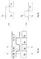
- Fig. 3 shows schematically, how two heat exchanger plates 1a, 1b are mounted to each other.
- the valleys 6a of the upper heat exchange plate 1a are mounted onto the tops 5b of the lower heat exchanger plate 1b.
- Fig. 4 schematically shows the relation of the crests and tops of the assembly of the two heat exchanger plates 1a, 1b. Parts of the upper heat exchanger plate 1a are shown with dotted lines and the corresponding parts of the lower heat exchanger plate 1b are shown in full lines.
- the distance A mentioned above is chosen to be so small that a gasket which is arranged in the groove 3 cannot be pressed through the gap.
- Fig. 5a shows the relation of the crests and tops of the assembly of two heat exchanger plates 1a, 1b of a second embodiment. Parts of the upper heat exchanger plate 1a are shown with dotted lines and the corresponding parts of the lower heat exchanger plate 1b are shown in full lines.
- the wavy shape of the external wall 7 is squared or almost squared rather than sine-shaped, like in Fig. 4 .
- Fig. 5b shows sectional views along the lines A-A and B-B of Fig. 5a . It can be seen that in section A-A the gap has disappeared.
- Fig. 6 shows schematically the relation of the crests and tops of the assembly of two heat exchanger plates 1a, 1b of a third embodiment.
- Fig. 6a shows a top view and Fig. 6b shows sectional views along lines A-A and B-B of Fig. 6a .
- the shape of the border lines 7a, 7b are illustrated as squared, but can also be of a sin-shape or any other curvy form. The shapes are shifted.
- the gap 14 between the two plates 1a, 1b have almost disappeared and is so small that there is no risk that a gasket will be pressed through.
- the two border lines 7a, 7b are at least almost identical. In other words, the border lines are shifted in relation to each other when compared to the embodiment of Fig. 4 and 5 .
Landscapes
- Engineering & Computer Science (AREA)
- Physics & Mathematics (AREA)
- Thermal Sciences (AREA)
- Mechanical Engineering (AREA)
- General Engineering & Computer Science (AREA)
- Heat-Exchange Devices With Radiators And Conduit Assemblies (AREA)
Abstract
Description
- The present invention relates to a heat exchanger plate comprising an edge, a groove running along the edge, and a corrugated area having tops and valleys between the groove and the edge, wherein the tops run substantially perpendicular to the edge and the groove comprises an external wall adjacent to the corrugated area and an internal wall.
- Such a heat exchanger plate is known, for example, from
EP 2 361 365 B1 . - The invention is in particular used for a high-pressure heat exchanger having a stack of such heat exchanger plates, wherein a gasket is arranged between two adjacent plates. The corrugated area along the edge forms contact points to the adjacent plates of the stacks.
- However, such a construction has the risk that a gap is formed into the cavity formed inside the outer wall of the groove. At high pressure the gasket which is accommodated in the groove tends to be pushed towards this cavity, thus making the heat exchanger leak.
- The object underlying the invention is to have a reliable plate-type heat exchanger of simple construction.
- This object is solved with a heat exchanger plate as described at the outset in that the external wall is in form of a wavy shape.
- The wavy shape of the external wall varies the size of the gap or, in a preferred embodiment, makes the gap so small that the gasket cannot be pressed out of the groove. Thus, the risk of a leakage of the heat exchanger formed by such heat exchanger plates is dramatically reduced.
- In an embodiment of the invention the wavy shape comprises crests and troughs, wherein the crests are closer to the edge than the troughs and wherein at least in a middle section of the edge the number of crests corresponds to the number of tops. Thus, it is possible to reduce the size of the gap at each top.
- In an embodiment of the invention the crests are arranged in the region of the tops. Thus, the gap is reduced exactly in the position, where it is need.
- In an embodiment of the invention the crests extend at least to an internal border of the corrugated area. In particular, it is possible that the crests extend beyond the internal border of the corrugated area. Thus, it is possible to close the gap completely.
- In an embodiment of the invention the groove comprises a varying width. This varying width is due to the fact that the external wall is in form of a wavy shape and that the internal wall does not follow the same shape.
- In an embodiment of the invention the internal wall is straight at least over a part of its length. This simplifies the production of the heat exchanger plate.
- In an additional or alternative embodiment of the invention the internal wall is not straight at least over a part of its length. However, it is possible to combine straight parts and non-straight parts of the internal wall. The particular form of the internal wall depends on the gasket used.
- In an embodiment of the invention the crests and troughs are rounded. Thus, there are no sharp edges which could damage the gasket.
- In an embodiment of the invention the crests and troughs are in form of a sinus wave. A sinus wave is a harmonic form keeping low stresses on the gasket.
- In another embodiment of the invention the crests and troughs are squared. This simplifies the production of the heat exchanger plate.
- An embodiment of the invention will now be described in more detail with reference to the drawing, wherein:
- Fig. 1
- shows a perspective view of an edge section of a heat exchanger plate,
- Fig. 2
- shows a top view of the edge section of the heat exchanger plate according to
Fig. 1 , - Fig. 3
- shows a perspective view of edge sections of two heat exchanger plates during assembling,
- Fig. 4
- schematically illustrates a relation between a corrugated area at the edge and the wave shape of the external wall.
- Fig. 5
- schematically shows a view of a second embodiment according to
Fig. 4 , and - Fig. 6
- schematically shows a third embodiment in a view according to
Fig. 4 . - In all Figures the same elements are denoted with the same reference numerals.
-
Fig. 1 shows in a perspective view an edge section of a heat exchanger plate 1 comprising an edge 2, agroove 3 running parallel to the edge 2, and a corrugated area 4 havingtops 5 andvalleys 6 between thegroove 3 and the edge 2. - The
tops 5 run substantially perpendicular to the edge 2. Thegroove 3 comprises anexternal wall 7 adjacent to the corrugated area 4 and aninternal wall 8 on the opposite side of theexternal wall 7. - The
external wall 7 is in form of a wavy shape, i.e. it is ondulated. Theexternal wall 7 comprisescrests 9 andtroughs 10. Thecrests 9 are closer to the edge 2 than thetroughs 10. - At least in a middle section of the edge 2 the number of
crests 9 corresponds to the number oftops 5. -
Crests 9 are arranged in the region of thetops 5. In a preferred embodiment a point of thecrests 9 closest to the edge 2 corresponds to a middle (in a direction parallel to the edge 2) of thetop 5. - The
crests 9 extend as close as possible to thetop 5. In the embodiment shown, there is a small distance A between aninternal border 11 of the corrugated area 4 and thecrests 9 of theinternal wall 7. However, it is possible that thecrests 9 extend at least to theinternal border 11 of the corrugated area 4. - Due to the wave shape of the
external border 7 the width of thegroove 3 varies. In other words, the distance between theexternal wall 7 and theinternal wall 8 varies. - In the embodiment shown, the
internal wall 8 is straight. However, it is possible to use aninternal wall 8 which is straight only over a part of its length or which is not straight. It is in addition possible to combine sections of theinternal wall 8 being straight and sections of the internal wall which are not straight. - The
crests 9 andtroughs 10 are rounded. It is possible to design theexternal wall 7 in form of a sinus wave or to design the external wall in a succession of squares or rectangles. -
Fig. 2 shows in addition aheat exchanging area 12 of the heat exchanger plate 1 having aherring bone pattern 13. -
Fig. 3 shows schematically, how twoheat exchanger plates valleys 6a of the upperheat exchange plate 1a are mounted onto the tops 5b of the lowerheat exchanger plate 1b. -
Fig. 4 schematically shows the relation of the crests and tops of the assembly of the twoheat exchanger plates heat exchanger plate 1a are shown with dotted lines and the corresponding parts of the lowerheat exchanger plate 1b are shown in full lines. - It can be seen that the
crests 9b of theexternal wall 7b of the lowerheat exchanger plate 1b extend to the tops 5b of the lowerheat exchanger plate 1b, whereas thecrests 9a of theexternal wall 7a of the upperheat exchanger plate 1a extend to the tops 5a of the upperheat exchanger plate 1a. - The distance A mentioned above is chosen to be so small that a gasket which is arranged in the
groove 3 cannot be pressed through the gap. The smaller the distance A, the smaller the gap and the lower is the risk that leakages occur. -
Fig. 5a shows the relation of the crests and tops of the assembly of twoheat exchanger plates heat exchanger plate 1a are shown with dotted lines and the corresponding parts of the lowerheat exchanger plate 1b are shown in full lines. - The wavy shape of the
external wall 7 is squared or almost squared rather than sine-shaped, like inFig. 4 . -
Fig. 5b shows sectional views along the lines A-A and B-B ofFig. 5a . It can be seen that in section A-A the gap has disappeared. -
Fig. 6 shows schematically the relation of the crests and tops of the assembly of twoheat exchanger plates -
Fig. 6a shows a top view andFig. 6b shows sectional views along lines A-A and B-B ofFig. 6a . - The shape of the
border lines - It can be seen that the
gap 14 between the twoplates border lines Fig. 4 and5 .
Claims (10)
- Heat exchanger plate (1) comprising an edge (2), a groove (3) running along the edge (2), and a corrugated area (4) having tops (5) and valleys (6) between the groove (3) and the edge (2), wherein the tops (5) run substantially perpendicular to the edge (2) and the groove (3) comprises an external wall (7) adjacent to the corrugated area (4) and an internal wall (8), characterized in that the external wall (7) is in form of a wavy shape.
- Heat exchanger plate according to claim 1, characterized in that the wavy shape comprises crests (9) and troughs (10), wherein the crests (9) are closer to the edge (2) than the troughs (10) and wherein at least in a middle section of the edge (2) the number of crests (9) corresponds to the number of tops (5).
- Heat exchanger plate according to claim 2, characterized in that the crests (9) are arranged in the region of the tops (5).
- Heat exchanger plate according to claim 3, characterized in that the crests (9) extend at least to an internal border (11) of the corrugated area (4).
- Heat exchanger plate according to claim 1 or 4, characterized in that the groove (3) comprises a varying width.
- Heat exchanger plate according to any of claims 1 to 5, characterized in that the internal wall (7) is straight at least over a part of its lengths.
- Heat exchanger plate according to any of claims 1 to 6, characterized in that the internal wall (7) is not straight at least over a part of its lengths.
- Heat exchanger plate according to any of claims 1 to 7, characterized in that the crests (9) and troughs (10) are rounded.
- Heat exchanger plate according to claim 8, characterized in that the crests (9) and troughs (10) are in form of a sinus wave.
- Heat exchanger plate according to claim 8, characterized in that the crests (9) and troughs (10) are squared.
Applications Claiming Priority (1)
| Application Number | Priority Date | Filing Date | Title |
|---|---|---|---|
| DKPA201901302A DK180498B1 (en) | 2019-11-07 | 2019-11-07 | Heat exchanger plate |
Publications (2)
| Publication Number | Publication Date |
|---|---|
| EP3819583A1 true EP3819583A1 (en) | 2021-05-12 |
| EP3819583B1 EP3819583B1 (en) | 2022-02-23 |
Family
ID=72240389
Family Applications (1)
| Application Number | Title | Priority Date | Filing Date |
|---|---|---|---|
| EP20192690.4A Active EP3819583B1 (en) | 2019-11-07 | 2020-08-25 | Heat exchanger plate |
Country Status (5)
| Country | Link |
|---|---|
| US (1) | US11473853B2 (en) |
| EP (1) | EP3819583B1 (en) |
| CN (1) | CN112781427B (en) |
| DK (2) | DK180498B1 (en) |
| RU (1) | RU2741170C1 (en) |
Citations (5)
| Publication number | Priority date | Publication date | Assignee | Title |
|---|---|---|---|---|
| JPH04217794A (en) * | 1990-03-06 | 1992-08-07 | Tranter Inc | Plate type heat exchanger |
| US5887650A (en) * | 1997-01-06 | 1999-03-30 | Tai Bong Industries, Inc. | Sealing device for laminated heat exchangers |
| DE19900629A1 (en) * | 1998-01-12 | 1999-07-15 | Apv Heat Exchanger As | Heat exchanger plate for use in plate-shaped heat exchanger |
| WO2010092556A1 (en) * | 2009-02-16 | 2010-08-19 | Luca Cipriani | A plate structure and gasket for a plate heat exchanger and respective plate heat exchanger |
| EP2361365A2 (en) * | 2008-12-16 | 2011-08-31 | Alfa Laval Corporate AB | Plate and gasket for a plate heat exchanger |
Family Cites Families (12)
| Publication number | Priority date | Publication date | Assignee | Title |
|---|---|---|---|---|
| GB668905A (en) * | 1949-03-26 | 1952-03-26 | Wedholms Aktiebolag | Improvements in heat exchangers of the plate type, particularly of pasteurising apparatus |
| DE19506281A1 (en) * | 1995-02-23 | 1996-08-29 | Schmidt Bretten Gmbh | Circumferential seal of a plate heat exchanger |
| JPH08271178A (en) * | 1995-03-29 | 1996-10-18 | Hisaka Works Ltd | Plate type heat exchanger |
| IL125113A (en) * | 1998-06-25 | 2001-08-26 | Pessach Seidel | Heat exchanger plates and sealing gaskets therefor |
| DK1196730T3 (en) * | 1999-06-14 | 2004-06-21 | Apv Heat Exchanger As | Plate for a heat exchanger |
| US6464101B1 (en) * | 2000-07-10 | 2002-10-15 | Illinois Tool Works Inc. | Hole plug with mechanically retained adhesive gasket |
| DE10035776C1 (en) * | 2000-07-22 | 2001-12-13 | Gea Ecoflex Gmbh | Plate heat exchanger for medical or food industry use has seals provided between stacked plates provided with nipples fitting through holes on plates |
| SE524783C2 (en) * | 2003-02-11 | 2004-10-05 | Alfa Laval Corp Ab | Plate package, plate heat exchanger and plate module |
| RU2282124C2 (en) * | 2004-11-26 | 2006-08-20 | Юрий Дмитриевич Фролов | Plate-type heat exchanger |
| SE532344C2 (en) * | 2007-12-21 | 2009-12-22 | Alfa Laval Corp Ab | Gasket support in heat exchanger and heat exchanger including gasket support |
| PT2886998T (en) * | 2013-12-18 | 2018-06-28 | Alfa Laval Corp Ab | Attachment means, gasket arrangement, heat exchanger plate and assembly |
| FR3024224B1 (en) * | 2014-07-25 | 2018-12-07 | Airbus Helicopters | PLATE HEAT EXCHANGER WITH STRUCTURAL REINFORCEMENTS FOR TURBOMOTEUR |
-
2019
- 2019-11-07 DK DKPA201901302A patent/DK180498B1/en active IP Right Grant
-
2020
- 2020-08-17 RU RU2020127414A patent/RU2741170C1/en active
- 2020-08-25 DK DK20192690.4T patent/DK3819583T3/en active
- 2020-08-25 EP EP20192690.4A patent/EP3819583B1/en active Active
- 2020-09-14 CN CN202010960790.3A patent/CN112781427B/en active Active
- 2020-11-05 US US17/090,444 patent/US11473853B2/en active Active
Patent Citations (6)
| Publication number | Priority date | Publication date | Assignee | Title |
|---|---|---|---|---|
| JPH04217794A (en) * | 1990-03-06 | 1992-08-07 | Tranter Inc | Plate type heat exchanger |
| US5887650A (en) * | 1997-01-06 | 1999-03-30 | Tai Bong Industries, Inc. | Sealing device for laminated heat exchangers |
| DE19900629A1 (en) * | 1998-01-12 | 1999-07-15 | Apv Heat Exchanger As | Heat exchanger plate for use in plate-shaped heat exchanger |
| EP2361365A2 (en) * | 2008-12-16 | 2011-08-31 | Alfa Laval Corporate AB | Plate and gasket for a plate heat exchanger |
| EP2361365B1 (en) | 2008-12-16 | 2015-10-14 | Alfa Laval Corporate AB | Plate and gasket for a plate heat exchanger |
| WO2010092556A1 (en) * | 2009-02-16 | 2010-08-19 | Luca Cipriani | A plate structure and gasket for a plate heat exchanger and respective plate heat exchanger |
Also Published As
| Publication number | Publication date |
|---|---|
| EP3819583B1 (en) | 2022-02-23 |
| DK3819583T3 (en) | 2022-04-19 |
| DK180498B1 (en) | 2021-05-27 |
| RU2741170C1 (en) | 2021-01-22 |
| US20210140722A1 (en) | 2021-05-13 |
| DK201901302A1 (en) | 2021-05-27 |
| US11473853B2 (en) | 2022-10-18 |
| CN112781427B (en) | 2022-08-23 |
| CN112781427A (en) | 2021-05-11 |
Similar Documents
| Publication | Publication Date | Title |
|---|---|---|
| EP2886997B1 (en) | Heat transfer plate and plate heat exchanger | |
| CN203464814U (en) | Stacked plate-type heat exchanger | |
| EP2363677B1 (en) | Method of manufacturing plate heat exchanger and plate heat exchanger | |
| KR20130031848A (en) | A heat exchanger plate and a plate heat exchanger | |
| KR20160114626A (en) | Heat exchanging board and board-type heat exchanger provided with heat exchanging board | |
| US10323883B2 (en) | Heat exchange plate for plate-type heat exchanger and plate-type heat exchanger provided with said heat exchange plate | |
| US4635714A (en) | Packing groove in plate member of plate heat exchanger | |
| KR20130087617A (en) | Heat exchanger | |
| EP3396293A1 (en) | Heat transfer plate and heat exchanger comprising a plurality of such heat transfer plates | |
| US20210131750A1 (en) | Heat exchanger plate | |
| EP3819583B1 (en) | Heat exchanger plate | |
| JP7214923B2 (en) | heat transfer plate | |
| CN211451981U (en) | Plate heat exchanger | |
| US11320207B2 (en) | Heat transfer plate for plate heat exchanger and plate heat exchanger with the same | |
| CN112762741A (en) | Plate heat exchanger | |
| FI3948134T3 (en) | A heat exchanger plate, and a plate heat exchanger | |
| CN109813159B (en) | Heat transfer plate for a plate heat exchanger and plate heat exchanger with a heat transfer plate | |
| CN220670294U (en) | Heat exchange plate, sealing gasket and heat exchanger | |
| EP0903554B1 (en) | Heat transfer plate for a plate heat exchanger. | |
| CN116892856A (en) | Heat exchange plate, sealing gasket and heat exchanger |
Legal Events
| Date | Code | Title | Description |
|---|---|---|---|
| PUAI | Public reference made under article 153(3) epc to a published international application that has entered the european phase |
Free format text: ORIGINAL CODE: 0009012 |
|
| STAA | Information on the status of an ep patent application or granted ep patent |
Free format text: STATUS: THE APPLICATION HAS BEEN PUBLISHED |
|
| AK | Designated contracting states |
Kind code of ref document: A1 Designated state(s): AL AT BE BG CH CY CZ DE DK EE ES FI FR GB GR HR HU IE IS IT LI LT LU LV MC MK MT NL NO PL PT RO RS SE SI SK SM TR |
|
| STAA | Information on the status of an ep patent application or granted ep patent |
Free format text: STATUS: REQUEST FOR EXAMINATION WAS MADE |
|
| 17P | Request for examination filed |
Effective date: 20210824 |
|
| RBV | Designated contracting states (corrected) |
Designated state(s): AL AT BE BG CH CY CZ DE DK EE ES FI FR GB GR HR HU IE IS IT LI LT LU LV MC MK MT NL NO PL PT RO RS SE SI SK SM TR |
|
| GRAP | Despatch of communication of intention to grant a patent |
Free format text: ORIGINAL CODE: EPIDOSNIGR1 |
|
| STAA | Information on the status of an ep patent application or granted ep patent |
Free format text: STATUS: GRANT OF PATENT IS INTENDED |
|
| GRAJ | Information related to disapproval of communication of intention to grant by the applicant or resumption of examination proceedings by the epo deleted |
Free format text: ORIGINAL CODE: EPIDOSDIGR1 |
|
| GRAP | Despatch of communication of intention to grant a patent |
Free format text: ORIGINAL CODE: EPIDOSNIGR1 |
|
| INTG | Intention to grant announced |
Effective date: 20211011 |
|
| RIN1 | Information on inventor provided before grant (corrected) |
Inventor name: KNUDSEN, IVAN Inventor name: NIELSEN, HELGE |
|
| INTG | Intention to grant announced |
Effective date: 20211029 |
|
| GRAS | Grant fee paid |
Free format text: ORIGINAL CODE: EPIDOSNIGR3 |
|
| GRAA | (expected) grant |
Free format text: ORIGINAL CODE: 0009210 |
|
| STAA | Information on the status of an ep patent application or granted ep patent |
Free format text: STATUS: THE PATENT HAS BEEN GRANTED |
|
| AK | Designated contracting states |
Kind code of ref document: B1 Designated state(s): AL AT BE BG CH CY CZ DE DK EE ES FI FR GB GR HR HU IE IS IT LI LT LU LV MC MK MT NL NO PL PT RO RS SE SI SK SM TR |
|
| REG | Reference to a national code |
Ref country code: GB Ref legal event code: FG4D |
|
| REG | Reference to a national code |
Ref country code: CH Ref legal event code: EP |
|
| REG | Reference to a national code |
Ref country code: DE Ref legal event code: R096 Ref document number: 602020001959 Country of ref document: DE |
|
| REG | Reference to a national code |
Ref country code: AT Ref legal event code: REF Ref document number: 1470784 Country of ref document: AT Kind code of ref document: T Effective date: 20220315 |
|
| REG | Reference to a national code |
Ref country code: IE Ref legal event code: FG4D |
|
| REG | Reference to a national code |
Ref country code: DK Ref legal event code: T3 Effective date: 20220412 |
|
| REG | Reference to a national code |
Ref country code: SE Ref legal event code: TRGR |
|
| REG | Reference to a national code |
Ref country code: NL Ref legal event code: FP |
|
| REG | Reference to a national code |
Ref country code: LT Ref legal event code: MG9D |
|
| REG | Reference to a national code |
Ref country code: AT Ref legal event code: MK05 Ref document number: 1470784 Country of ref document: AT Kind code of ref document: T Effective date: 20220223 |
|
| PG25 | Lapsed in a contracting state [announced via postgrant information from national office to epo] |
Ref country code: RS Free format text: LAPSE BECAUSE OF FAILURE TO SUBMIT A TRANSLATION OF THE DESCRIPTION OR TO PAY THE FEE WITHIN THE PRESCRIBED TIME-LIMIT Effective date: 20220223 Ref country code: PT Free format text: LAPSE BECAUSE OF FAILURE TO SUBMIT A TRANSLATION OF THE DESCRIPTION OR TO PAY THE FEE WITHIN THE PRESCRIBED TIME-LIMIT Effective date: 20220623 Ref country code: NO Free format text: LAPSE BECAUSE OF FAILURE TO SUBMIT A TRANSLATION OF THE DESCRIPTION OR TO PAY THE FEE WITHIN THE PRESCRIBED TIME-LIMIT Effective date: 20220523 Ref country code: LT Free format text: LAPSE BECAUSE OF FAILURE TO SUBMIT A TRANSLATION OF THE DESCRIPTION OR TO PAY THE FEE WITHIN THE PRESCRIBED TIME-LIMIT Effective date: 20220223 Ref country code: HR Free format text: LAPSE BECAUSE OF FAILURE TO SUBMIT A TRANSLATION OF THE DESCRIPTION OR TO PAY THE FEE WITHIN THE PRESCRIBED TIME-LIMIT Effective date: 20220223 Ref country code: ES Free format text: LAPSE BECAUSE OF FAILURE TO SUBMIT A TRANSLATION OF THE DESCRIPTION OR TO PAY THE FEE WITHIN THE PRESCRIBED TIME-LIMIT Effective date: 20220223 Ref country code: BG Free format text: LAPSE BECAUSE OF FAILURE TO SUBMIT A TRANSLATION OF THE DESCRIPTION OR TO PAY THE FEE WITHIN THE PRESCRIBED TIME-LIMIT Effective date: 20220523 |
|
| PG25 | Lapsed in a contracting state [announced via postgrant information from national office to epo] |
Ref country code: PL Free format text: LAPSE BECAUSE OF FAILURE TO SUBMIT A TRANSLATION OF THE DESCRIPTION OR TO PAY THE FEE WITHIN THE PRESCRIBED TIME-LIMIT Effective date: 20220223 Ref country code: LV Free format text: LAPSE BECAUSE OF FAILURE TO SUBMIT A TRANSLATION OF THE DESCRIPTION OR TO PAY THE FEE WITHIN THE PRESCRIBED TIME-LIMIT Effective date: 20220223 Ref country code: GR Free format text: LAPSE BECAUSE OF FAILURE TO SUBMIT A TRANSLATION OF THE DESCRIPTION OR TO PAY THE FEE WITHIN THE PRESCRIBED TIME-LIMIT Effective date: 20220524 Ref country code: FI Free format text: LAPSE BECAUSE OF FAILURE TO SUBMIT A TRANSLATION OF THE DESCRIPTION OR TO PAY THE FEE WITHIN THE PRESCRIBED TIME-LIMIT Effective date: 20220223 Ref country code: AT Free format text: LAPSE BECAUSE OF FAILURE TO SUBMIT A TRANSLATION OF THE DESCRIPTION OR TO PAY THE FEE WITHIN THE PRESCRIBED TIME-LIMIT Effective date: 20220223 |
|
| PG25 | Lapsed in a contracting state [announced via postgrant information from national office to epo] |
Ref country code: IS Free format text: LAPSE BECAUSE OF FAILURE TO SUBMIT A TRANSLATION OF THE DESCRIPTION OR TO PAY THE FEE WITHIN THE PRESCRIBED TIME-LIMIT Effective date: 20220623 |
|
| PG25 | Lapsed in a contracting state [announced via postgrant information from national office to epo] |
Ref country code: SM Free format text: LAPSE BECAUSE OF FAILURE TO SUBMIT A TRANSLATION OF THE DESCRIPTION OR TO PAY THE FEE WITHIN THE PRESCRIBED TIME-LIMIT Effective date: 20220223 Ref country code: SK Free format text: LAPSE BECAUSE OF FAILURE TO SUBMIT A TRANSLATION OF THE DESCRIPTION OR TO PAY THE FEE WITHIN THE PRESCRIBED TIME-LIMIT Effective date: 20220223 Ref country code: RO Free format text: LAPSE BECAUSE OF FAILURE TO SUBMIT A TRANSLATION OF THE DESCRIPTION OR TO PAY THE FEE WITHIN THE PRESCRIBED TIME-LIMIT Effective date: 20220223 Ref country code: EE Free format text: LAPSE BECAUSE OF FAILURE TO SUBMIT A TRANSLATION OF THE DESCRIPTION OR TO PAY THE FEE WITHIN THE PRESCRIBED TIME-LIMIT Effective date: 20220223 Ref country code: CZ Free format text: LAPSE BECAUSE OF FAILURE TO SUBMIT A TRANSLATION OF THE DESCRIPTION OR TO PAY THE FEE WITHIN THE PRESCRIBED TIME-LIMIT Effective date: 20220223 |
|
| REG | Reference to a national code |
Ref country code: DE Ref legal event code: R097 Ref document number: 602020001959 Country of ref document: DE |
|
| PG25 | Lapsed in a contracting state [announced via postgrant information from national office to epo] |
Ref country code: AL Free format text: LAPSE BECAUSE OF FAILURE TO SUBMIT A TRANSLATION OF THE DESCRIPTION OR TO PAY THE FEE WITHIN THE PRESCRIBED TIME-LIMIT Effective date: 20220223 |
|
| PLBE | No opposition filed within time limit |
Free format text: ORIGINAL CODE: 0009261 |
|
| STAA | Information on the status of an ep patent application or granted ep patent |
Free format text: STATUS: NO OPPOSITION FILED WITHIN TIME LIMIT |
|
| 26N | No opposition filed |
Effective date: 20221124 |
|
| PG25 | Lapsed in a contracting state [announced via postgrant information from national office to epo] |
Ref country code: MC Free format text: LAPSE BECAUSE OF FAILURE TO SUBMIT A TRANSLATION OF THE DESCRIPTION OR TO PAY THE FEE WITHIN THE PRESCRIBED TIME-LIMIT Effective date: 20220223 |
|
| PG25 | Lapsed in a contracting state [announced via postgrant information from national office to epo] |
Ref country code: LU Free format text: LAPSE BECAUSE OF NON-PAYMENT OF DUE FEES Effective date: 20220825 |
|
| REG | Reference to a national code |
Ref country code: BE Ref legal event code: MM Effective date: 20220831 |
|
| P01 | Opt-out of the competence of the unified patent court (upc) registered |
Effective date: 20230617 |
|
| PG25 | Lapsed in a contracting state [announced via postgrant information from national office to epo] |
Ref country code: IE Free format text: LAPSE BECAUSE OF NON-PAYMENT OF DUE FEES Effective date: 20220825 |
|
| PG25 | Lapsed in a contracting state [announced via postgrant information from national office to epo] |
Ref country code: BE Free format text: LAPSE BECAUSE OF NON-PAYMENT OF DUE FEES Effective date: 20220831 |
|
| PGFP | Annual fee paid to national office [announced via postgrant information from national office to epo] |
Ref country code: TR Payment date: 20230823 Year of fee payment: 4 Ref country code: IT Payment date: 20230831 Year of fee payment: 4 |
|
| PGFP | Annual fee paid to national office [announced via postgrant information from national office to epo] |
Ref country code: SE Payment date: 20230710 Year of fee payment: 4 Ref country code: DK Payment date: 20230814 Year of fee payment: 4 Ref country code: DE Payment date: 20230705 Year of fee payment: 4 Ref country code: FR Payment date: 20230721 Year of fee payment: 4 |
|
| REG | Reference to a national code |
Ref country code: CH Ref legal event code: PL |
|
| PG25 | Lapsed in a contracting state [announced via postgrant information from national office to epo] |
Ref country code: CY Free format text: LAPSE BECAUSE OF FAILURE TO SUBMIT A TRANSLATION OF THE DESCRIPTION OR TO PAY THE FEE WITHIN THE PRESCRIBED TIME-LIMIT Effective date: 20220223 Ref country code: CH Free format text: LAPSE BECAUSE OF NON-PAYMENT OF DUE FEES Effective date: 20230831 |
|
| PG25 | Lapsed in a contracting state [announced via postgrant information from national office to epo] |
Ref country code: MK Free format text: LAPSE BECAUSE OF FAILURE TO SUBMIT A TRANSLATION OF THE DESCRIPTION OR TO PAY THE FEE WITHIN THE PRESCRIBED TIME-LIMIT Effective date: 20220223 Ref country code: HU Free format text: LAPSE BECAUSE OF FAILURE TO SUBMIT A TRANSLATION OF THE DESCRIPTION OR TO PAY THE FEE WITHIN THE PRESCRIBED TIME-LIMIT; INVALID AB INITIO Effective date: 20200825 |
|
| PGFP | Annual fee paid to national office [announced via postgrant information from national office to epo] |
Ref country code: NL Payment date: 20240705 Year of fee payment: 5 |